1
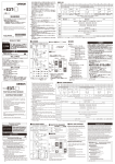
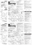
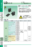
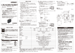
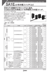
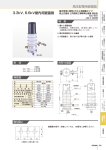
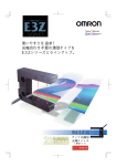
光電センサ
レーザタイプ
取扱説明書
このたびは、本製品をお買い上げいただきまして、まことにありがとうございます。
ご使用に際しては、次の内容をお守りください。
・ 電気の知識を有する専門家がお取り扱いください。
・この取扱説明書をよくお読みになり、十分にご理解のうえ、正しくご使用ください。
・この取扱説明書はいつでも参照できるよう大切に保管してください。
The following notice applies only to products that carry the CE mark:
Notice:
This is a class A product. In residential areas it may cause radio
interference, in which case the user may be required to take adequate
measures to reduce interference.
E3Z-L□□1/-L□□3
10.8
10.4
感度ボリウム**
動作切替スイッチ**
動作表示灯*
安定表示灯*
20
17
CLASS1
LASER
PRODUCT
2.1
E3Z-L□□□
・取り扱い上の注意
形E3Z-L□□□は可視光レーザを放射しています。直接見つめ
ないでください。
レーザビームの光路を終端するようにご使用ください。
終端材は反射の少ないつや消し塗装面等によりレーザ光が目に
影響しないように配慮下さい。
光路に鏡面反射体がある場合は、反射光路に対してビームを閉
じ込めるようにしてください。
開放して使用しなければならない場合光路は、
目の高さを避ける
ようにしてください。
・レーザ機器に関しては国内外でレーザ安全対策が規定されてい
ます。
国内で使用される場合、国内で組み付けられて海外輸出される
場合、
これらを分けて次に簡単に説明します。
■外形寸法図
レンズ
光軸
31
25.4
形
■取り扱い上の注意
(3)米国を除く諸外国の場合
ヨーロッパへの輸出に関しては、
EN60825−1
:
2001が適用さ
れます。
形E3Z-L□□□はこの規格の定めるCLASS1に分類されます。
レーザに関するラベル表示
センサ側面に下図の説明ラベルが貼られています。
取付金具等でラベルの表示面が隠れる場合は、付属のラベルシ
ールを金具もしくは本製品の近傍に貼り付けてください。
18
15.5
レーザ安全について
LASER
ビニル絶縁丸形コード
標準長さ2m、4dia.
2-M3
(1)国内の場合
レーザ製品によって使用者に障害が発生することを防止する目
的で、国際電気基準(IEC)
をもとに日本工業規格「レーザ製品
の放射安全規格」
J
IS C6802が制定されています。
形E3Z- L□□□はこの規格の定めるJ
IS規格クラス1に分類さ
れます。
レーザに関するラベル表示
センサ側面に下図の説明ラベルが貼られています。
取付金具等でラベルの表示面が隠れる場合は、付属のラベルシ
ールを金具もしくは本製品の近傍に貼り付けてください。
*透過形の投光器は電源表示灯のみ
**透過形の投光器にはないため形状が異なります。
* 7 9 7 8 9 4 6 - 6 C *
© OMRON Corporation 2005 All Rights Reserved.
クラス1
レーザー製品
E3Z-L□□6/-L□□8
安全上のご注意
●警告表示
10.8
10.4
(2)米国の場合
機器搭載して米国へ輸出する場合、米国のレーザ安全規格
FDA(food and Drug Administration)の規制を受けます。
形E3Z- L□□□は本規格に定めるクラスⅡに分類されます。
下図を参照の上、本体ラベルを貼り替えてください
注意
安定表示灯*
レンズ
20
17
2.1
製品本体側面に貼り付けてください。
警告/証明ラベル
光軸
CAUTION
LASER RADIATION
DO NOT STARE INTO BEAM
PEAK POWER
4.5mW
PULSE DURATION 2.3μs
WAVE LENGTH
655nm
CLASS II LASER PRODUCT
This laser product complies with
21 CFR 1040, 10 and 1040, 11,
OMRON Corporation
735-5 higashiokoji-cho, karasuma-shichijo,
shimogyo-ku,Kyoto 660-8216 JAPAN
Place of manufactur:
AYABE Factory, OMRON Corp,
Manufactured in
18
15.5
AC電源では絶対に使用しないで下さい。
破裂の恐れがあります。
動作表示灯*
レーザ放出開口ラベル
警告/証明ラベル
31
25.4
注意
正しい取扱いをしなければ、この危険のために、
時に軽傷・中程度の傷害を負ったり、あるいは
物的損害を受ける恐れがあります。
感度ボリウム**
動作切替スイッチ**
10.4
●警告表示の意味
コード部に巻きつけてください。
2-M3
M8×1
9.75
レーザ放出開口ラベル
AVOID EXPOSURE
LASER LIGHT
*透過形の投光器は電源表示灯のみ
**透過形の投光器にはないため形状が異なります。
RADIATIONS EMITTED FROM
THIS APRTURE
安全上の要点
以下に示すような項目は、安全を確保する上で必要なことですので
必ず守ってください。
(1)引火性、
爆発性ガスの環境では使用しないでください。
(2)この製品は、分解したり、修理、改造をしないでください。
(3)電源電圧は、仕様電圧
(DC12∼24V±10%)
でご使用ください。
(4)負荷は、定格以下でご使用ください。
使用上の注意
(1)下記の設置場所では使用しないでください。
①直射日光があたる場所
②湿度が高く、結露する恐れがある場所
③腐食性ガスのある場所
④本体に直接、振動や衝撃が伝わる場所
(2)接続、取り付けについて
①最大電源電圧はDC26.4Vです。通電前に電源電圧が最大
電源電圧以下であることを確認してください。
②電力線、動力線と光電スイッチの配線が同一配管または同一
ダクトで行われると誘導を受け、誤動作あるいは破損の原因と
なる場合もありますので、別配線またはシールドコードの使用を
原則としてください。
③コードの延長は0.3mm2以上の線を用い、100m以下としてくだ
さい。
④コード部は強く引っ張らないようにしてください。
⑤光電スイッチを取り付ける際、ハンマーなどでたたきます
と、耐水機能が損なわれますのでご注意ください。また、
ネジはM3のものをご使用ください。
◎M8メタルコネクタについて
⑥コネクタの抜差は必ず電源を切ってから行なってください。
⑦コネクタの抜差は必ずコネクタカバー部を持って行なってください。
⑧固定具は必ず手で締めてください。プライヤなどを使用さ
れますと破損の原因になります。
⑨適正締め付けトルクは0.3∼0.4N・mです。締め付けが不十分
ですと保護構造が保てなくなったり、振動でゆるむことがあります。
(3)清掃について
シンナー類は、製品表面を溶かしますので避けてください。
(4)電源について
市販のスイッチングレギュレータをご使用の際はFG
(フレーム・グラ
ンド端子)
を接地してお使いください。
(5)電源リセット時間について
電源を入れてから光電スイッチが検出可能になる時間は100ms
ですので、電源投入後100ms以降にてご使用ください。負荷と
光電スイッチが別電源に接続されている場合は必ず光電スイッ
チの電源を先に投入して下さい。
(6)電源のOFFについて
電源OFF時に出力パルスが発生する場合がありますので負荷あ
るいは負荷ラインの電源を先にOFFされることをお勧めします。
(7)負荷短絡保護について
この機種は、負荷短絡保護機能を備えていますが、負荷は絶対
に短絡しないでください。負荷には定格を超える電流を絶対に流
さないでください。負荷短絡が生じた場合は出力がOFFとなりま
すので配線を見直したうえで電源を再投入してください。短絡保
護回路がリセットされます。
また負荷短絡保護は定格負荷電流
の1.8倍以上の電流が流れますと動作します。
L負荷を使用され
る場合は突入電流が定格負荷電流の1.8倍以下のものをご使
用ください。
(8)耐水性について
IP67ですが、水中、降雨中、
および屋外での使用は避けてください。
(9)産業廃棄物として処理して下さい。
■取り付け図
■定格性能
検出方式
形式
回帰反射形
距離設定形
形E3Z-LL63/-LL68
形E3Z-LR61/-LR66
形E3Z-LL61/-LL66
形E3Z-LL81/-LL86
形E3Z-LL83/-LL88
形E3Z-LR81/-LR86
0.3∼15m(形E39-R1使用時) 20∼300mm(白紙□100mm) 25∼300mm(白紙□100mm)
0.2∼7m(形E39-R12使用時)20∼160mm(黒紙□100mm) 25∼100mm(黒紙□100mm)
0.2∼7m(形E39-R6使用時)
透過形
形E3Z-LT61/-LT66
形E3Z-LT81/-LT86
NPN
PNP
60m
検出距離
設定距離範囲
―
応差の距離
白黒誤差
―
―
40∼300mm(白紙□100mm) 40∼300mm(白紙□100mm)
40∼160mm(黒紙□100mm) 40∼100mm(黒紙□100mm)
定格検出距離の5%以下
5%(距離100mm)
5%(距離160mm)
赤色LD(655nm)
JIS/IEC クラス1,FDA CLASSⅡ JIS/IEC クラス1,FDA CLASSⅡ
JIS/IEC クラス1,FDA CLASSⅡ
2mW以下
1mW以下
4.
5mW以下
DC12∼24V±10% リップル(p-p)10%以下
投光器:
15mA以下
30mA以下
受光器:
20mA以下
光源(発光波長)
電源電圧
消費電流
取り付け金具
(別売り)
形E39-L104
締め付けトルクは
0.5N・m以下と
してください
負荷電源電圧DC26.
4V以下、
負荷電流100mA以下
オープンコレクタ出力
入光時ON/しゃ光時ON スイッチ切替式
制御出力
出力残留電圧
残留電圧1V以下
(負荷電流10mA未満の場合)
:残留電圧2V以下
(負荷電流10∼100mA未満の場合)
電源逆接保護/負荷短絡保護
電源逆接保護/負荷短絡保護/相互干渉防止機能/出力逆接保護
/出力逆接保護
保護回路
応答時間
周囲温度
使用周囲湿度
保護構造
ケース
材質
表示部
レンズ部
動作・復帰:各0.
5ms以下
動作・復帰:各1ms以下
動作時:−10∼+55℃、保存時:−25∼+70℃
(ただし、氷結、結露しないこと)
動作時:
35∼85%RH、保存時35∼95%RH
(ただし、氷結、結露しないこと)
I
EC60529
:
I
P67
ポリブチレンテレフタレート
(PBT)
変性ポリアリレート
変性ポリアリレート
アクリル樹脂
変性ポリアリレート
■出力段回路図
ご使用に際してのご承諾事項
出力形態
形式
出力回路
NPN出力
形E3Z-L□6□
動作表示灯(橙)
1
茶
PNP出力
形E3Z-L□8□
DC12∼24V
安定表示灯(緑)
3
コネクタ ピン番号
②は空端子
青
光電スイッチ
主回路
DC12∼24V
茶
コネクタ ピン番号
②は空端子
100mA以下
4
(制御出力)
安定表示灯(緑)
0V
透過形の投光器
1
動作表示灯(橙)
(制御出力)
負荷
黒
4
光電スイッチ
100mA以下
主回路
3
黒
青
負荷
0V
①安全を確保する目的で直接的または間接的に人体を検出する用途に、本製品を使用し
ないでください。同用途には、当社センサカタログに掲載している安全センサをご使用く
ださい。
②下記用途に使用される場合、当社営業担当者までご相談のうえ仕様書などによりご確
認いただくとともに、定格・性能に対し余裕を持った使い方や、万一故障があっても危険
を最小にする安全回路などの安全対策を講じてください。
a)屋外の用途、
潜在的な化学的汚染あるいは電気的妨害を被る用途
またはカタログ、
取扱説明書等に記載のない条件や環境での使用
b)原子力制御設備、
焼却設備、
鉄道・航空・車両設備、
医用機械、
娯楽機械、
安全装置、
および行政機関や個別業界の規制に従う設備
c)人命や財産に危険が及びうるシステム・機械・装置
d)ガス、
水道、
電気の供給システムや24時間連続運転システムなどの
高い信頼性が必要な設備
e)その他、
上記 a) ∼ d) に準ずる、
高度な安全性が必要とされる用途
*上記は適合用途の条件の一部です。当社のベスト、総合カタログ・データシート等最新版
のカタログ、
マニュアルに記載の保証・免責事項の内容をよく読んでご使用ください。
コネクタピン番号
1
茶
光電
DC12∼24V
営業統轄事業部
東京都品川区大崎1-11-1 ゲートシティ大崎ウエストタワー14F
②は空端子
④は空端子
スイッチ
主回路
0V
3
青
(〒141-0032)
●営業にご用の方も、技術的なお問い合せの方も、
フリーコールにお電話ください。
音声ガイダンスが流れますので、案内に従って操作ください。
0 1 2 0 - 9 1 9 - 0 6 6 (フリーコール)
携帯電話・PHSなどではご利用いただけませんので、
その場合は下記電話番号へおかけください。
055-982-5015 (通話料がかかります)
〔技術のお問い合わせ時間〕
■営業時間:9:00∼12:00/13:00∼19:00
(土・日・祝祭日は17:00まで)
■営 業 日:年末年始を除く
上記フリーコール以外に 055-982-5002 (通話料がかかります)
におかけいただくことにより、
直接センシング機器の技術窓口につながります。
コネクタピン配置
形 E3ZーL□□6/ ーL□□8
〔営業のお問い合わせ時間〕
■営業時間:9:00∼12:00/13:00∼17:30
■営 業 日:土・日・祝祭日/春期・夏期・年末年始休暇を除く
●FAXによるお問い合わせは
お客様相談室 FAX055-982-5051
●その他のお問い合せ先
納期・価格・修理・サンプル・承認図は貴社のお取引先、
または貴社担当オムロン営業員にご相談ください。
R
Manufacturer:
Omron Corporation,
Sensing Devices Division H.Q.
Industrial Sensors Division
& Application Sensors Division
Shiokoji Horikawa, Shimogyo-ku,
Kyoto, 600-8530 JAPAN
The following notice applies only to products that carry the CE mark:
Notice:
This is a class A product. In residential areas it may cause radio
interference, in which case the user may be required to take adequate
measures to reduce interference.
© OMRON Corporation 2005 All Rights Reserved.
Precautions on Safety
Meaning of Signal Words
●
CAUTION
Indicates a potentially hazardous situation
which, if not avoided, may result in minor or
moderate injury or in property damage.
Warnings
●
CAUTION
Do not connect sensor to AC power supply.
Risk of explosion.
(1)Application in Japan
According to JIS C6802, the safety measures required of the
user are stipulated according to the class of the laser device. The
E3Z- L□□□ is classified as a class-1 laser according to JIS
C6802.
Laser stickers
The following stickers are attached to the side of the sensor.
2.1
Vinyl insulated round cord
Standard length 2m、4dia.
2-M3
*Only power indicator is on a light source of Separate type.
**The form differs because a light source of Separate type does not have it.
クラス1
レーザー製品
(2) USA
When a laser device is exported to the USA, it falls the laser
regulations of the FDA (Food and Drug Administration). The
E3Z- L□□□ is classified as a class-? laser by the FDA, and it
has already been registered with the CDRH (Center for Devices
and Radiological Health). Ask your OMRON representative for
details.
Laser Labels
Technical standards have been provided with the product. When
exporting to the USA, refer to the following illustration and
replace the label with the caution label.
It is assumed that the E3Z- L□□□ will be incorporated into a
final system device.
When incorporating the E3Z- L□□□, comply with the
following technical standard: US Federal Low 21 CFR 1040.10
and 1040.11
E3Z-L□□6/-L□□8
Sensitivity adjuster**
Operation mode switch**
10.8
10.4
TRACEABILITY INFORMATION:
Representative in EU:
Omron Europe B.V.
Wegalaan 67-69
2132 JD Hoofddorp,
The Netherlands
Lens
Optical axis
Operation indicator*
Stability indicator*
Lens
Aperture labels
20
17
2.1
Thank you for selecting OMRON product. This sheet primarily describes precautions required in installing and
operating the product.
Before operating the product, read the sheet thoroughly to
acquire sufficient knowledge of the product. For your convenience, keep the sheet at your disposal.
20
17
Optical axis
Caution / Certification and Identification labels
This laser product complies with
21 CFR 1040, 10 and 1040, 11,
OMRON Corporation
735-5 higashiokoji-cho, karasuma-shichijo,
shimogyo-ku,Kyoto 660-8216 JAPAN
Place of manufactur:
AYABE Factory, OMRON Corp,
Manufactured in
CAUTION
LASER RADIATION
DO NOT STARE INTO BEAM
PEAK POWER
4.5mW
PULSE DURATION 2.3μs
WAVE LENGTH
655nm
CLASS II LASER PRODUCT
31
25.4
INSTRUCTION SHEET
Operation indicator*
Stability indicator*
CLASS1
LASER
PRODUCT
10.4
PHOTOELECTRIC SENSOR
LASER TYPE
Sensitivity adjuster**
Operation mode switch**
18
15.5
E3Z-L□□□
precaution
The E3Z-L□□□ emits a visible laser beam. Never stare into
the beam. Be sure that the end of the beam path is terminated.
The best material for terminating the beam is a surface painted
with matt paint. If there are refractive surface in the beam path,
be sure that the reflected beam path is contained. If containment
is not possible for the application, do not allow the beam to
travel at eye level.
●Laser safety measures for laser devices are stipulated both in
Japan and overseas. Hear, two cases are described: Application
in Japan and Application in a device to be shipped overseas.
18
15.5
Model
●Handling
E3Z-L□□1/-L□□3
31
25.4
■Handling Precautions
■DIMENSIONS
10.8
10.4
(3) Regions except the USA
When exporting to countries other than the USA, the E3Z- L
□□□is classified as a class-? laser according to EN60825-1:
2001.
Laser stickers
The following stickers are attached to the side of the sensor.
Laser Safety
2-M3
M8×1
9.75
Caution / Certification and
Identification labels
Aperture labels
*Only power indicator is on a light source of Separate type.
**The form differs because a light source of Separate type does not have it.
AVOID EXPOSURE
LASER LIGHT
RADIATIONS EMITTED FROM
THIS APRTURE
Precautions for Safe Use
Be sure to follow the safety precautions below for added safety.
(1)Do not use the sensor under the environment with explosive or
ignition gas.
(2)Never disassemble, repair nor tamper with the product.
(3)Keep the supply voltage within the specified range.
(12to24V
DC±10%)
(4)Do not use the sensor over the rated values.
Precautions for Correct Use
(1)Do not use the product under the following conditions.
①In the place exposed to the direct sunlight.
②In the place where humidity is high and condensation may occur.
③In the place where corrosive gas exists.
④In the place where vibration or shock is directly transmitted
to the product.
(2)Connection and Mounting
①Be sure that before making supply the supply voltage is less
than themaximum rated supply voltage. (26.4V DC)
②There are some cases where the photoelectric switch
cable is unavoidably laid in a tube or duct together with a
hightension or power line.
③This causes an induction, possibly resulting in malfunction
or damage.
In principal, the cable should be separately laid or shielded.
For extending wires, use a cable 0.3mm2 min. and 100m
max. in length.
④Do not pull the wire strongly.
⑤Excessive force (hitting by hammer, etc.) should not be put
on the photoelectric switch because it may damage its
water-resistance characteristic. Use M3 screws to mount the
photoelectric switch.
◎M8metal connector
⑥Plug in or out the connector after surly turning off a power
supply.
⑦Plug in or out the connector with a cover part of it.
⑧Fasten a fixed implement by hand. If you use a plaier, it may
be cause of malfunction or damage to it.
⑨Proper bolting torque is 0.3 to 0.4N・m to keep water-resistance.
(3)Cleaning
Do not use thinner such as alcohol and benzine because it may
melt a surface of a product.
(4)Power supply
When using a commercially available switching regulator, be
sure to ground the FG (Frame Ground) terminals.
(5)Power supply reset time
The photoelectric switch will begin sensing no later than 100ms
after the power is turned on. If the load and the photoelectric
switch is connected to different power supply, the photoelectric
switch must be always turned on first.
(6)Turning off the power supply
When turning off the power, output pulse may be generated.
We recommend turning off the power supply of the load or load
line first.
(7)Load short circuit protection
This product is provided with function of load short circuit
protection. However, be never short-circuited of the load.
Please do not throw the current that exceeds ratings into the
load. Control output is turned off when this function operates.
After checking of wiring and load current, make power supply
again. Then the circuit is reset. Load short circuit protection
operates when the current is 1.8 times over than the rated load
current. The inrush current should be 1.8 times less than the
rated load current when L load is used.
(8)Water resistance
Though this is type IP67, do not use in the water, rain or
outdoors.
(9)Please process it as industrial waste.
Detection system
NPN
Type
PNP
Separate type
E3Z-LT61/-LT66
E3Z-LT81/-LT86
Distance-setting type
E3Z-LL61/-LL66
E3Z-LL63/-LL68
E3Z-LL81/-LL86
E3Z-LL83/-LL88
20 to 300mm
25 to 300mm
(white
paper 100X100mm)
(white paper 100X100mm)
60m
20 to 160mm
25 to 100mm
(Black paper 100X100mm) (Black paper 100X100mm)
40 to 300mm
40 to 300mm
(white paper 100X100mm) (white paper 100X100mm)
―
40 to 160mm
40 to 100mm
(Black paper 100X100mm) (Black paper 100X100mm)
―
5% of setting distance max
―
5%(of 100mm)
5%(of 160mm)
Visble wavelength for the semiconductor laser: 655 nm
JIS/IEC Class1, FDA CLASSⅡ JIS/IEC Class1, FDA CLASSⅡ
JIS/IEC Class1, FDA CLASSⅡ
2mW max.
1mW max.
4.5mW max.
12 to 24 V DC +/- 10%, ripple (p-p): 10% max.
Light sauce: 15mA max.
30mA max.
Receiver: 20mA max.
Detecting distance
Setting distance
Hysteresis
Black/white error
Light source
Supply voltage
Current consumption
Retroreflective type
E3Z-LR61/-LR66
E3Z-LR81/-LR86
0.3 to 15m(with E39-R1)
0.2 to 7m(with E39-R12)
0.2 to 7m(with E39-R6)
■MOUNTING
Mounting bracket (option)
Type E39-L104
Use tightening torque
0.5N・m max.
Load power supply voltage 26.4 VDC max., load current 100mA max.
Open collector output
Light-ON/Dark-ON switch selectable
Control output
Residual voltage
Response time
Ambient Temperature
Ambient humidity
Protection structure
Case
Material Display
Lens
1 V or less: Load current less than 10mA. 2 V or less: Load current less than 10 to 100mA.
0.5ms max.
1ms max.
Operating -10 to +55℃, Storage -25 to +70℃(no freezing and condensation)
Operating 35 to 85%, Storage 35 to 95% (no freezing and condensation)
IEC60529 : IP67
Polybutylene Terephthalate resin (PBT)
Denatured Polyarylate resin
Denatured Polyarylate resin
Acrylic resin
Denatured Polyarylate resin
■OUTPUT CIRCUIT DIAGRAM
Output
Type
Output circuit
Suitability for Use
NPN output
E3Z-L□6□
Operation indicator
(orange)
1
Brown
Stability indicator
(green)
12 to 24V DC
Load
(Control output)
Photoelectric
switch
main circuit
PNP output
E3Z-L□8□
4
3
Blue
Connector pin arrangement
Brown
12 to 24V DC
Photoelectric
switch
main circuit
3
Photoelectric
switch
main circuit
4
(Control output)
Stability indicator
(green)
Brown
12 to 24V DC
Connector
pin arrangement
Terminal 2 is not used.
100mA max.
Black
Load
3
Blue
OMRON shall not be responsible for conformity with any standards, codes, or
regulations that apply to the combination of the products in the customer's
application or use of the product.
0V
NEVER USE THE PRODUCTS FOR AN APPLICATION INVOLVING
SERIOUS RISK TO LIFE OR PROPERTY WITHOUT ENSURING THAT THE
SYSTEM AS A WHOLE HAS BEEN DESIGNED TO ADDRESS THE RISKS,
AND THAT THE OMRON PRODUCT IS PROPERLY RATED AND
INSTALLED FOR THE INTENDED USE WITHIN THE OVERALL
EQUIPMENT OR SYSTEM.
See also Product catalog for Warranty and Limitation of Liability.
0V
Blue
CONNECTOR PIN ARRANGEMENT
TYPE E3Z-L□□6/ -L□□8
0V
1
Take all necessary steps to determine the suitability of the product for the
systems, machines, and equipment with which it will be used.
Know and observe all prohibitions of use applicable to this product.
Light source of Separate type
1
Connector
pin arrangement
Terminal 2 is not used.
Black
100mA max.
Operation indicator
(orange)
THE PRODUCTS CONTAINED IN THIS SHEET ARE NOT SAFETY RATED.
THEY ARE NOT DESIGNED OR RATED FOR ENSURING SAFETY OF
PERSONS, AND SHOULD NOT BE RELIED UPON AS A SAFETY
COMPONENT OR PROTECTIVE DEVICE FOR SUCH PURPOSES.
Please refer to separate catalogs for OMRON's safety rated products.
Terminal 2 is not used.
Terminal 4 is not used
EUROPE
OMRON EUROPE B.V. Sensor Business Unit
Carl-Benz Str.4, D-71154 Nufringen Germany
Phone:49-7032-811-0 Fax: 49-7032-811-199
NORTH AMERICA
OMRON ELECTRONICS LLC
One Commerce Drive Schaumburg,IL 60173-5302 U.S.A
Phone:1-847-843-7900 Telephone Consultation
1-800-55-OMRON Fax : 1-847-843-7787
ASIA-PACIFIC
OMRON ASIA PACIFIC PTE LTD
83 Clemenceau Avenue,#11-01 UE Square,Singapore 239920
Phone : 65-6-835-3011 /Fax :65-6-835-2711
OMRON Corporation
n