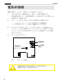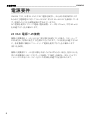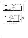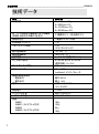
1
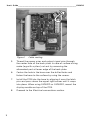
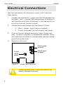
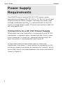
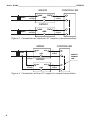
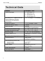
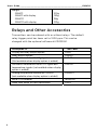
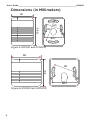
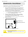
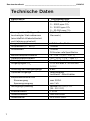
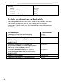
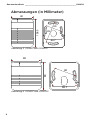
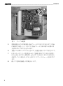
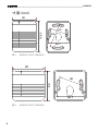
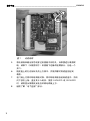
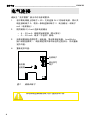
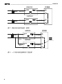
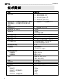
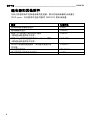
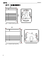
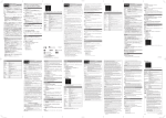
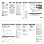
User’s Guide www.vaisala.com Vaisala CARBOCAP® Carbon Dioxide Transmitter Series GMW20 M210196EN-B User’s Guide _____________________________________________________ GMW20 User’s Guide _____________________________________________________ GMW20 Table of Contents Basics of the GMW20 Series ................................................ 2 Mounting ...................................................................................... 2 Electrical Connections ............................................................ 4 Power Supply Requirements................................................ 5 Technical Data ........................................................................... 7 Relays and Other Accessories ............................................. 8 Dimensions (in Millimeters)................................................... 9 1 User’s Guide _____________________________________________________ GMW20 Basics of the GMW20 Series Vaisala’s GMW20 series transmitters use silicon based CARBOCAP sensor with excellent stability and reliability properties. The series consist of the following transmitter types: GMW21 and display version GMW21D GMW22 and display version GMW22D (80x108.5x35) mm (80x80x35) mm The GMW20 series transmitter is calibrated as shipped from the factory. In benign environments the recommended calibration interval is five years. In case adjustment is needed, contact Vaisala Service or local Vaisala representative. The reading of the GMW20 can be checked and adjusted with the serial com adapter 19040GM and the calibration software available from www.vaisala.com. The checking in the field can also be done with calibration gas and a multimeter. Mounting 2 1. The GMW20 is shipped ready for installation onto a standard wallbox or onto a surface mounting. 2. Drill a hole in the surface where the transmitter will be mounted , then pull the wiring through the drilled hole. 3. Open the transmitter cover by pushing forward and turning a screwdriver head in the slot located at the bottom between the cover and the back plate. 4. Remove the printed circuit board (PCB) by pressing upwards with a screwdriver (see Figure 1 on page 3). User’s Guide _____________________________________________________ GMW20 Figure 1 3 Cable routing 5. Thread the power wires and output signal wire through the center hole of the back plate. In case of surface wiring, make (e.g.with a pliers) cut-out by removing the attenuated part at lower edge of the back plate. 6. Center the hole in the base over the drilled holes and fasten the base to the surface by using the screws. 7. Install the PCB into the base by aligning it over the latch pins and press down the upper right corner until it snaps into place. When using GMW21D or GMW22D, mount the display module on top of the PCB. 8. Proceed to the Electrical connections section. User’s Guide _____________________________________________________ GMW20 Electrical Connections See the requirements for the power supply in the Technical Data section. 1. Connect the nominal 24 V supply on the PCB between the terminals + and -. Connect the common wire to terminal 0 and the other wire either to terminal V (voltage output) or to the terminal mA (current output). 2. Choose the current output with the jumper 0/4 mA – – 4 ... 20mA: jumper shorts the pins (default) 0 ... 20 mA: disconnect (do not discard) the jumper. 3. If the unit has an optional accessory (relay, display and relay, LonWorks interface, or temperature module), follow the procedure described in the applicable manuals before repositioning the cover. 4. Reposition the cover. Power supply terminals Output signal terminals Current output jumper Figure 2 Jumper and Terminals Connecting power wires to the output terminal can seriously damage the product. 4 User’s Guide _____________________________________________________ GMW20 Power Supply Requirements The GMW20 uses a nominal 24 VAC/VDC power supply maintaining a voltage of 18...30 VDC or 20...26 VAC for all load conditions and all mains voltages. Although the power input includes a halfwave rectifier, it is recommended to use a DC supply to avoid current peaks (Current consumption: peak 170 mA, average 85 mA). Connections to a 24 VAC Power Supply When more than one transmitter is connected to one 24 VAC transformer, a common loop is formed and the risk of a shortcircuit increases. To avoid this, separate floating supply for each transmitter is recommended (see Figure 3). In case where several transmitters have to share one transformer, the phase ( ) must always be connected to 24V connector in each transmitter to maintain the "polarity" and to avoid short-circuit via shared common line at the controller as shown in Figure 4. 5 User’s Guide _____________________________________________________ GMW20 CONTROLLER GMW20 24VAC Supply voltage 24V OUT GND Signal output GMW20 24VAC Supply voltage 24V OUT GND Signal output Figure 3 Connection of separate AC supplies (recommended) GMW20 24V 24VAC OUT GND Supply voltage Supply voltage CONTROLLER Signal output GMW20 24V OUT GND SHAR ED COMMON LINE Signal output Figure 4 Connection of one AC supply to several transmitters 6 User’s Guide _____________________________________________________ GMW20 Technical Data Property Measuring ranges Accuracy at 25 °C against certified factory references (includes repeatability and calibration uncertainty) Long-term stability Response time (0 ... 63%) Warm-up time Operating temperature range Storage temperature range Humidity range Output signal for CO2 Resolution of analog outputs Optional outputs Recommended external load current output voltage output Power supply Power consumption Housing material Housing colour 7 Description / value 0 ... 2000 ppm CO2 0 ... 5000 ppm CO2 0 ... 10 000 ppm CO2 0 ... 20 000 ppm CO2 (2 % of range + 2 % of reading) < 5 % of range / 5 years 1 minute 1 minute 15 minutes full specifications -5 … +45 °C (+23 … +113 °F) -20 ... +70 °C (-4 … +158 °F) 0 ... 85 % RH , non-condensing Selectable 0...20 mA or 4...20 mA and 0...10 V 8 bits Relay output LonWorks® interfaces max. 500 min. 1 k nominal 24 VAC/VDC (18 ... 30 VDC) < 2.5 W ABS plastic NCS 0502-G50Y User’s Guide _____________________________________________________ GMW20 Weight GMW21 GMW21 with display GMW22 GMW22 with display 100g 130g 90g 120g Relays and Other Accessories Transmitters can be ordered with or without relays. The default relay trigger point has been set to 1000 ppm. This can be changed with the optional software kit 19222GM. Description Or d d er Co e Display and relay output option GMI21 Relay output option GMR20 LonWorks module with CO2 signal GML20 (Not available when display option is added) LonWorks module with both CO2 signal and GML20T temperature signals (not available when display option is added) Analog temperature module for GMW21 GMA20T (not available when display option is added) Serial COM adapter 19040GM Hand-held meter for field verification GM70 8 User’s Guide _____________________________________________________ GMW20 Dimensions (in Millimeters) 80 108.5 60 83 66.7 Figure 5 GMW21 and GMW21D 80 80 60 66.7 Figure 6 GMW22 and GMD22D 9 Legal notice © Vaisala 2010 No part of this manual may be reproduced in any form or by any means, electronic or mechanical (including photocopying), nor may its contents be communicated to a third party without prior written permission of the copyright holder. The contents are subject to change without prior notice. Please observe that this manual does not create any legally binding obligations for Vaisala towards the customer or end user. All legally binding commitments and agreements are included exclusively in the applicable supply contract or Conditions of Sale. Warranty For warranty information, visit our Internet pages at www.vaisala.com/services/warranty.html This product is covered by an extended 2 year warranty Technical Support For technical questions, contact the Vaisala technical support via email: [email protected] For contact information of Vaisala Service Centers, see www.vaisala.com/services/servicecenters.html *M210196EN* Benutzerhandbuch www.vaisala.com CO2-Messwertgeber Vaisala CARBOCAP® der Serie GMW20 Benutzerhandbuch _______________________________________________ GMW20 Benutzerhandbuch _______________________________________________ GMW20 Inhalt Allgemeine Informationen zur Serie GMW20 .................... 2 Montage ........................................................................................... 2 Elektrische Anschlüsse ............................................................... 4 Anforderungen der Stromversorgung.................................. 5 Technische Daten ......................................................................... 7 Relais und weiteres Zubehör.................................................... 8 Abmessungen (in Millimeter) ................................................... 9 1 Benutzerhandbuch _______________________________________________ GMW20 Allgemeine Informationen zur Serie GMW20 In Vaialas Messwertgebern der Serie GMW20 wird ein auf Silikon basierender CARBOCAP-Sensor verwendet, der einwandfreie Stabilität und Zuverlässigkeit garantiert. Die Serie besteht aus den folgenden Messwertgebertypen: GMW21 und Displayversion GMW21D GMW22 und Displayversion GMW22D (80 x 108,5 x 35) mm (80 x 80 x 35) mm Die Messwertgeber der Serie GMW20 werden werkseitig kalibriert. In unproblematischen Bedingungen sollte eine Kalibrierung etwa alle fünf Jahre durchgeführt werden. Wenden Sie sich an den Vaisala Service oder Ihren lokalen Vaisala Vertreter, wenn eine Justierung erforderlich ist. Kalibrieren Sie das GMW20 unter Verwendung des SeriencomAdapters 19040GM und der Kalibrierungs-Software von www.vaisala.com. Das Ablesen im Feld kann auch mit Kalibriergas und einem Multimeter erfolgen. Montage 2 1. Der GMW20 wird installationsfertig zur Montage in einer Standard-Unterputzdose oder an der Wand geliefert. 2. Bohren Sie ein Loch in die Oberfläche, an der der Messwertgeber montiert werden soll. Ziehen Sie dann die Verkabelung durch das gebohrte Loch. 3. Öffnen Sie die Abdeckung des Messwertgebers, indem Sie sie nach vorne drücken und einen Schraubenzieher in den Schlitz zwischen Abdeckung und Rückwandblech schieben. 4. Entfernen Sie die Hauptplatine, indem Sie sie mit einem Schraubendreher nach oben drücken (siehe Abbildung 1 unten 3). Benutzerhandbuch _______________________________________________ GMW20 Abbildung 1 Verkabelung 3 5. Ziehen Sie das Stromkabel und das Ausgangssignalkabel durch die Öffnung am Rückwandblech. Wird keine UPDose verwendet, durchstoßen Sie (z. B. mit einer Zange) eine Öffnung für das Kabel, indem Sie die dünnere Stelle am unteren Rand der Bodenplatte entfernen. 6. Zentrieren Sie das Loch an der Unterseite über den gebohrten Löchern, und befestigen Sie die Platte mithilfe der Schrauben an der Fläche. 7. Setzen Sie die Hauptplatine ein, indem Sie sie an den Raststiften ausrichten und die obere rechte Ecke hinunterdrücken, bis Sie ein Klicken hören. Setzen Sie bei den Modellen GMW21D/GMW22D zuerst die Anzeige auf die Hauptplatine. 8. Fahren Sie mit dem Abschnitt „Elektrische Anschlüsse“ fort. Benutzerhandbuch _______________________________________________ GMW20 Elektrische Anschlüsse Informationen zu den Anforderungen der Stromversorgung finden Sie im Abschnitt mit den technischen Daten. 1. Die Versorgungsspannung von 24 V muss zwischen den Klemmen + und – auf der Hauptplatine angeschlossen werden. Die gemeinsame Masseader wird an Klemme 0 und die Signalader an Klemme V (Spannungsausgang) oder an Klemme mA (Stromausgang) angeschlossen. 2. Der Stromausgang wird mit der Steckbrücke 0/4 mA gewählt: – 4 ... 20 mA: bei gesteckter Brücke (Vorgabe) – 0 ... 20 mA: bei gezogener Brücke 3. Wenn optionales Zubehör (Relais, Display und Relais, LonWorks Interface oder Temperaturmodul) installiert sind, befolgen Sie die Anweisungen in den entsprechenden Handbüchern, bevor Sie die Abdeckung wieder anbringen. 4. Bringen Sie die Abdeckung wieder an. Schraubklemmen Ausgangssignalklemmen Stromausgangsbrücke Abbildung 2 Steckbrücke und Klemmen Der Stromanschluss an die Stromausgangsklemmen kann das Produkt schwer beschädigen. 4 Benutzerhandbuch _______________________________________________ GMW20 Anforderungen der Stromversorgung Der Messwertgeber der Serie GMW20 wird mit einer Nennspannung von 24 V AC/V DC betrieben. Die Stromversorgung sollte eine Spannung zwischen 18 und 30 V DC oder 20 und 26 V AC bei allen Lastbedingungen und Netzspannungsschwankungen bereitstellen können. Die Eingangsstufe enthält einen Einweggleichrichter. Um Stromspitzen zu vermeiden, wird die Verwendung einer DC-Versorgung empfohlen (Stromaufnahme des Messwertgebers: max. 170 mA, durchschnittlich 85 mA). Anschluss an eine 24-VAC-Stromversorgung Wenn mehr als ein Messwertgeber an einen 24-VAC-Transformator angeschlossen werden, kann es zur Bildung einer Masseschleife kommen, und es besteht ein erhöhtes Kurzschlussrisiko. Um dies zu vermeiden, wird für jeden Messwertgeber eine separate Spannungsversorgung empfohlen (siehe Abbildung 3). Wenn mehrere Messwertgeber an einen Transformator angeschlossen werden müssen, muss der Außenleiter ( ) immer mit dem 24V-Anschluss in jedem Messwertgeber verbunden werden, um die Polarität aufrecht zu erhalten und Kurzschlüsse über die gemeinsame Erdungsverbindung am Steuergerät zu verhindern, wie in Abbildung 4 dargestellt. 5 Benutzerhandbuch _______________________________________________ GMW20 STEUERGERÄT GMW20 AUS24 V GANG GND Versorgung24 V AC sspannung Signalausgang GMW20 24 V AC AUSGANG GND 24 V Versorgungsspannung Signalausgang Abbildung 3 Anschluss separater AC-Versorgungen (empfohlen) GMW20 24 V 24 V AC Versorgungsspannung Versorgungsspannung GND AUSGANG STEUERGERÄT Signalausgang GEMEINSAME ERDUNGSVERBINDUNG GMW20 24 V AUS- GANG GND Signalausgang Abbildung 4 Anschluss einer AC-Versorgung an mehrere Messwertgeber 6 Benutzerhandbuch _______________________________________________ GMW20 Technische Daten Eigenschaft B Messbereiche Genauigkeit bei 25 °C gemäß bescheinigter Werksreferenzen (einschließlich Wiederholbarkeit und Kalibrierunsicherheit) Langzeitstabilität Ansprechzeit (0 ... 63 %) Aufwärmzeit Betriebstemperaturbereich Lagertemperaturbereich Feuchtigkeitsbereich Ausgangssignal CO2 Auflösung der Analogausgänge Optionale Ausgänge Empfohlene externe Last Stromausgang Spannungsausgang Versorgungsspannung Stromverbrauch Gehäusematerial Gehäusefarbe 7 eschreibung/Wert 0 ... 2000 ppm CO2 0 ... 5000 ppm CO2 0 ... 10.000 ppm CO2 0 ... 20.000 ppm CO2 (2 % v. Ew. + 2 % des Messwerts) < 5 % v. Ew../5 Jahre 1 Minute 1 Minute 15 Minuten volle Spezifikation -5 ... +45 °C (-23 ... +113 °F) -20 ... F+70 °C (-4 ... +158 °F) 0 ... 85 % rF, nicht kondensierend 0...20 mA oder 4...20 mA und 0...10 V 8 Bits Relaisausgang LonWorks® -Schnittstellen max. 500 min. 1 k nominal 24 V AC/V DC (18 ... 30 V DC) < 2,5 W ABS-Kunststoff NCS 0502-G50Y Benutzerhandbuch _______________________________________________ GMW20 Gewicht GMW21 GMW21 mit Display GMW22 GMW22 mit Display 100 g 130 g 90 g 120 g Relais und weiteres Zubehör Messwertgeber können mit oder ohne Relais bestellt werden. Der Relaisschaltpunkt wurde werkseitig auf 1000 ppm eingestellt. Dieser kann mit dem optionalen Softwarezubehör 19222GM geändert werden. Beschreibung B Optionen Display und Relaisausgang Option Relaisausgang LonWorks-Modul mit CO2-Signal (Nicht verfügbar, wenn die Option Display gewählt wird) LonWorks-Modul mit CO2-Signal und Temperatursignalen (nicht verfügbar, wenn die Option Display gewählt wird) Analoges Temperaturmodul für GMW21 (nicht verfügbar, wenn die Option Display gewählt wird) Serieller COM-Adapter Tragbares Messgerät für Feldkalibrierung 8 estellnummer GMI21 GMR20 GML20 GML20T GMA20T 19040GM GM70 Benutzerhandbuch _______________________________________________ GMW20 Abmessungen (in Millimeter) 80 60 108.5 83 66.7 Abbildung 5 GMW21 und GMW21D 80 80 60 66.7 Abbildung 6 GMW22 und GMW22D 9 Rechtlicher Hinweis © Vaisala 2010 Ohne vorherige schriftliche Genehmigung des Copyright-Inhabers darf dieses Handbuch weder ganz noch teilweise in keiner Form und durch kein Mittel, sei es elektronisch oder mechanisch (einschließlich Fotokopien), vervielfältigt werden. Dies gilt auch für die Weitergabe des Inhalts dieses Handbuchs an Dritte. Der Inhalt kann ohne vorherige Ankündigung geändert werden. Diese Anleitung ist keine rechtsverbindliche Vereinbarung zwischen Vaisala und dem Kunden oder Benutzer. Alle rechtsverbindlichen Verpflichtungen und Vereinbarungen sind ausschließlich im anwendbaren Liefervertrag oder den Verkaufsbedingungen enthalten. Gewährleistung Informationen zur Gewährleistung finden Sie auf unseren Internetseiten unter www.vaisala.com/services/warranty.html. Dieses Produkt umfasst eine Gewährleistung von zwei Jahren. Technische Unterstützung Bei technischen Fragen wenden Sie sich per E-Mail unter der folgenden Adresse an den technischen Support von Vaisala: [email protected] Kontaktinformationen zu den Vaisala Servicezentren finden Sie unter www.vaisala.com/services/servicecenters.html 取扱説明書 www.vaisala.com ヴァイサラ CARBOCAP® 変換器シリーズ GMW20 取扱説明書 _______________________________________________________ GMW20 取扱説明書 _______________________________________________________ GMW20 目次 GMW20 シリーズの基本 ............................................... 2 取り付け .................................................................... 2 電気的接続 ............................................................... 4 電源要件................................................................... 5 技術データ ................................................................ 7 リレーおよびその他のアクセサリー.................................. 8 寸法 (mm).................................................................. 9 1 取扱説明書 _______________________________________________________ GMW20 GMW20 シリーズの基本 ヴァイサラの GMW20 シリーズ変換器は、シリコンベースの CARBOCAP セ ンサを使用し、優れた安定性と信頼性を備えています。このシリーズは以下の 種類の変換器で構成されています。 GMW21 およびディスプレイバージョン GMW21D (80x108.5x35) mm GMW22 およびディスプレイバージョン GMW22D (80x80x35) mm GMW20 シリーズ変換器は工場から出荷される際に校正されています。一般 的な環境では、5 年間隔で校正を行うことをお勧めします。調整が必要な場 合は、ヴァイサラ サービスまたはお近くのヴァイサラ代理店にお問い合わせく ださい。 GMW20 は連続アダプター19040GM および www.vaisala.com からの口径測 定ソフトウェアと調節することができる。現地での確認は、校正用ガスとマルチ メータを使用して行うこともできます。 取り付け 2 1. GMW20 は、標準の壁面ボックスや壁面に取り付け可能な状態で出荷 されています。 2. 変換器を取り付ける壁面にドリルで穴を開け、その穴から配線を引き出 します。 3. 底部にある、カバーと背面プレートの間のスロットにドライバーのヘッド を差し込んで回し、変換器のカバーを開きます。 4. ドライバーで上に押し上げ、プリント回路基板 (PCB) を取り外します (3 ページの 図 1 を参照)。 取扱説明書 _______________________________________________________ GMW20 図1 3 ケーブル配線 5. 電源配線と出力信号配線を背面プレートの中央の穴に通します。壁面 に配線する場合、(ペンチなどで) 背面プレート下部の端にある薄い部 分を取り外して切り欠きを入れます。 6. 基盤の穴と開けた穴の中心を合わせ、基盤を壁面にネジで固定します。 7. PCB をラッチピン上に位置合わせして基盤に取り付け、所定の位置に はめ込まれるまで右上隅を押し込みます。GMW21D または GMW22D を使用している場合は、PCB 上部にディスプレイモジュールを取り付け ます。 8. 続いて「電気的接続」の作業を行います。 取扱説明書 _______________________________________________________ GMW20 電気的接続 電源の要件については、「技術データ」を参照してください。 1. PCB の公称 24 V 電源を端子 + と端子 - の間に接続します。 共通配線を端子 0 に、他の配線を端子 V (電圧出力) または端子 mA (電流出力) に接続します。 2. ジャンパー 0/4 mA で次のいずれかの電流出力を選択します。 – 4~20 mA: ジャンパーでピンを短絡させる (初期設定) – 0~20 mA: ジャンパーを外す (破棄しないでください) 3. ユニットにアクセサリー (リレー、ディスプレイとリレー、LonWorks イン ターフェース、または温度モジュール) がオプションで付属している場 合、カバーを元に戻す前に該当のマニュアルに記載されている手順を 実行してください。 4. カバーを元に戻します。 電源端子 電流出力 ジャンパー 図2 出力信号 端子 ジャンパーと端子 電源配線を出力端子に接続すると、製品に重大な 損傷を引き起こす可能性があります。 4 取扱説明書 _______________________________________________________ GMW20 電源要件 GMW20 では、公称 24 VAC/VDC 電源を使用し、あらゆる負荷条件および あらゆる主電源電圧に対して 18~30 VDC または 20~26 VAC を維持していま す。電源入力には半波整流器が含まれていますが、 DC 電源を使用してピーク電流 (電流消費 : ピーク時 170 mA、平均 85 mA) を回避することをお勧めします。 24 VAC 電源への接続 複数の変換器を 1 つの 24 VAC 変圧器に接続している場合、コモンループ が形成され、短絡が発生する危険が大きくなります。この状況を回避するため に、各変換器に個別のフローティング電源を使用することをお勧めします (図 3 を参照)。 複数の変換器で 1 つの変圧器を共有しなければならない場合、位相 ( ) を 常に各変換器の 24V コネクターに接続して「極性」を維持し、図 4 に示すコ ントローラの共有コモンラインを介した短絡を回避する必要があります。 5 取扱説明書 _______________________________________________________ GMW20 コントローラ GMW20 24 VAC 電源電圧 24 V OUT 信号出力 GND GMW20 24 V 24 VAC 電源電圧 図3 OUT 信号出力 GND 個別の AC 電源の接続 (推奨) GMW20 24 V 24 VAC 電源 電圧 電源 電圧 図4 6 OUT GND コントローラ 信号出力 GMW20 24 V OUT GND 信号出力 1 つの AC 電源の複数の変換器への接続 取扱説明書 _______________________________________________________ GMW20 技術データ 特性 測定範囲 説明/値 0~2000 ppm CO2 0~5000 ppm CO2 0~10 000 ppm CO2 0~20 000 ppm CO2 25 °C での認定工場基準に対する精度 (再現性と校正の不確かさを含む) 長期安定性 応答時間 (0~63 %) ウォームアップ時間 (範囲の 2 % 動作温度範囲 保管温度範囲 湿度範囲 CO2 の出力信号 アナログ出力分解能 オプション出力 推奨外部負荷抵抗 電流出力 電圧出力 電源 消費電力 ハウジング材質 ハウジングの色 重量 GMW21 GMW21 (ディスプレイ付き) GMW22 GMW22 (ディスプレイ付き) 7 + 指示値の 2 %) < 範囲の 5 %/5 年間 1分 1分 15 分 (フルスペック) -5~+45 °C -20~+70 °C 0~85 % RH (結露がないこと) 0~20 mA または 4~20 mA (選択可能)、0~10 V 8 ビット リレー出力 LonWorks® インターフェース 最大 500 最小 1 k 公称 24 VAC/VDC (18~30 VDC) < 2.5 W ABS プラスチック NCS 0502-G50Y 100 g 130 g 90 g 120 g 取扱説明書 _______________________________________________________ GMW20 リレーおよびその他のアクセサリー 変換器はリレー付きまたはリレーなしで注文できます。初期設定では、リレー のトリガーポイントは 1000 ppm に設定されています。トリガーポイントは、オプ ションのソフトウェアキット 19222GM で変更できます。 説明 ディスプレイおよびリレー出力オプション リレー出力オプション CO2 信号付き LonWorks モジュール (ディスプレイオプション追加時は利用できません) CO2 信号および温度信号付き LonWorks モジュール (ディ スプレイオプション追加時は利用できません) GMW21 用アナログ温度モジュール (ディスプレイオプション追加時は利用できません) シリアル COM アダプター 現地検証用ハンディタイプメーター 8 注文コード GMI21 GMR20 GML20 GML20T GMA20T 19040GM GM70 取扱説明書 _______________________________________________________ GMW20 寸法 (mm) 80 60 108.5 83 66.7 図5 GMW21 および GMW21D 80 80 60 66.7 図6 9 GMW22 および GMW22D 法律上の表示 © Vaisala 2010 本取扱説明書のいずれの部分も、電子的または機械的手法 (写真複写も含む) であ ろうと、またいかなる形式または手段によっても複製してはならず、版権所有者の書面 による許諾なしに、その内容を第三者に伝えてはなりません。 本取扱説明書の内容は予告なく変更されることがあります。 本取扱説明書は、顧客あるいはエンドユーザーに対してヴァイサラ社を法的に拘束す る義務を生じさせるものではないことをご承知ください。法的に拘束力のあるお約束あ るいは合意事項はすべて、該当する供給契約書または販売条件書に限定して記載さ れています。 保証 保証については、以下をご参照ください。www.vaisala.com/services/warranty.html 本製品は、2 年間の延長保証の対象です。 技術サポート 技術的なお問い合わせについては、以下まで E メールでヴァイサラ社技術サ ポートにご連絡ください。 [email protected] ヴァイサラサービスセンターのお問い合わせ窓口については、以下をご参照 ください。 www.vaisala.com/services/servicecenters.html 操作手册 www.vaisala.com Vaisala CARBOCAP® 二氧化碳变送器系列 GMW20 操作手册_________________________________________________________ GMW20 操作手册_________________________________________________________ GMW20 目录 GMW20 系列的基本功能 ........................................................... 2 安装................................................................................................. 2 电气连接......................................................................................... 4 电源要求......................................................................................... 5 技术数据......................................................................................... 7 继电器和其他附件......................................................................... 8 尺寸(以毫米表示)..................................................................... 9 1 操作手册 ____________________________________ GMW20 GMW20 系列的基本功能 Vaisala 的 GMW20 系列变送器使用基于硅的 CARBOCAP 传感器, 铸就了变送器卓越的稳定性和可靠性。该系列包括以下变送器类型: GMW21 和显示屏版本 GMW21D GMW22 和显示屏版本 GMW22D (80x108.5x35) mm (80x80x35) mm GMW20 系列变送器在出厂前已经进行了校准。在良好的环境中,推荐 的校准时间间隔为 5 年。如果需要进行调整,请与 Vaisala 服务或当地 的 Vaisala 代表联系。 GMW20 可以检查和调整与连续适配器 19040GM 和从 www.vaisala.com 的定标软件。使用校准气体和万用表也可以进行现 场检查。 安装 2 1. GMW20 出厂后即可安装在标准墙盒或表面上。 2. 在将安装变送器的表面中钻一个孔,然后将配线从所钻的孔中 穿过。 3. 前推变送器外盖,并将螺丝刀头旋转到位于外盖和后面板之间底部 的插槽中,以打开变送器外盖。 4. 使用螺丝刀向上按压,取出印刷电路板 (PCB)(请参见第 3 页的 图 1)。 操作手册_________________________________________________________ GMW20 图1 3 电缆线路 5. 将电源线和输出信号线穿过后面板中间的孔。如果要进行表面配 线,请取下(如使用钳子)后面板下边缘的较薄部分,创造一个 开口。 6. 使底座上的孔在所钻孔的上方居中,并使用螺钉将底座固定到 表面。 7. 在闩销上方将印刷电路板对准,将印刷电路板安装到底座中,然后 向下按右上角,直至其卡入到位。使用 GMW21D 或 GMW22D 时,请将显示屏模块安装在印刷电路板上方。 8. 继续了解“电气连接”部分。 操作手册 ____________________________________ GMW20 电气连接 请参见“技术数据”部分中对电源的要求。 1. 在印刷电路板上的端子 + 和 – 之间连接 24 V 的标称电源。将公共 线连接到端子 0,将另一条线连接到端子 V(电压输出)或端子 mA(电流输出)。 2. 使用跳线 0/4 mA 选择电流输出 – 4 ... 20 mA:跳线使针脚短接(默认情况) – 0 ... 20 mA:断开(不丢弃)跳线。 3. 如果装置具有选用附件(继电器、显示屏和继电器、LonWorks 接口或温度模块),请按照适用手册中所述的过程执行,然后重新 定位外盖。 4. 重新定位外盖。 电源端子 输出信号 端子 电流输 出跳线 图2 跳线和端子 将电源线连接到输出端子会严重损害本产品。 4 操作手册_________________________________________________________ GMW20 电源要求 GMW20 使用 24 VAC/VDC 的标称电源,对于所有负载情况和所有电 源电压保持电压为 18...30 VDC 或 20...26 VAC。尽管电源输入包括半 波整流器,但建议使用直流电源来避免出现电流峰值(电流消耗:峰值 为 170 mA,平均为 85 mA)。 连接到 24 VAC 电源 将多个变送器连接到一个 24 VAC 变压器时,会形成一个公共循环,将 增加发生短路的风险。要避免出现此情况,建议为每个变送器使用单独 的浮动电源(请参见 图 3)。 如果多个变送器必须共享一个变压器,则相位 ( ) 必须始终连接到每个 变送器中的 24V 接头,从而通过控制器上的共享公共线保持“极性” 并避免短路,如 图 4 所示。 5 操作手册 ____________________________________ GMW20 控制器 GMW20 24VAC 供电电压 24V 信号输出 GMW20 24VAC 供电电压 24V 信号输出 图 3 单独交流电源的连接(推荐) GMW20 24V 24VAC 供电 电压 供电 电压 信号输出 GMW20 24V 图 4 一个交流电源连接到多个变送器 6 控制器 信号输出 操作手册_________________________________________________________ GMW20 技术数据 参数 测量范围 温度为 25 °C 时相对于认证的工厂参考 值的精确度(包括重复性和校准不确 定性) 长期稳定性 响应时间 (0 ...63%) 预热时间 工作温度范围 储存温度范围 湿度范围 CO2 输出信号 模拟输出的精度 可选输出 建议的外部负载 电流输出 电压输出 电源 功耗 外壳材料 外壳颜色 重量 GMW21 GMW21(带显示屏) GMW22 GMW22(带显示屏) 7 说明/值 0 ... 2000 ppm CO2 0 ... 5000 ppm CO2 0 ... 10 000 ppm CO2 0 ... 20 000 ppm CO2 (范围的 2 % + 读数的 2 %) < 范围的 5%/5 年 1 分钟 1 分钟 15 分钟全规格 -5 … +45 °C (+23 … +113 °F) -20 ... +70 °C (-4 … +158 °F) 0 ... 85% 的相对湿度,无冷凝 可以选择范围 0...20 mA 或 4...20 mA 以及 0...10 V 8位 继电器输出 LonWorks® 接口 最大 500 最小 1 k 标称 24 VAC/VDC (18 ... 30 VDC) < 2.5 W ABS 塑料 NCS 0502-G50Y 100g 130g 90g 120g 操作手册 ____________________________________ GMW20 继电器和其他附件 可以订购包括或不包括继电器的变送器。默认的继电器触发点设置为 1000 ppm。可以使用可选软件套件 19222GM 更改该设置。 说明 显示屏和继电器输出选件 继电器输出选件 采用 CO2 信号的 LonWorks 模块 (添加显示屏选件后不可用) 采用 CO2 信号和温度信号的 LonWorks 模块 (添加显示屏选件后不可用) GMW21 的模拟温度模块(添加显示屏选件后 不可用) 串行通信适配器 用于现场验证的手持式测量仪 8 订货代码 GMI21 GMR20 GML20 GML20T GMA20T 19040GM GM70 操作手册_________________________________________________________ GMW20 尺寸(以毫米表示) 80 60 108.5 83 66.7 图 5 GMW21 和 GMW21D 80 80 60 66.7 图 6 GMW22 和 GMW22D 9 法律声明 © Vaisala 2010 未经版权所有人事先书面许可,不得以任何形式或手段, 无论是电子的还是机械的 (其中包括影印),对本手册的任何部分进行复制,也不得将本手册的内容传达 给第三方。 本手册内容如有变更,恕不另行通知。 请注意,本手册并不会导致 Vaisala 公司要对客户或最终用户付任何连带法律责 任。所有的法律连带责任和协议只包含在适用供货合同或销售条款中。 担保 有关担保信息,请访问我公司网站: www.vaisala.com/services/warranty.html 本产品包括 2 年的延长保修期 技术支持 有关技术问题,请通过电子邮件与 Vaisala 技术支持部门联系: [email protected] 有关 Vaisala 服务中心的联系信息,请参见 www.vaisala.com/services/servicecenters.html Legal notice © Vaisala 2010 No part of this manual may be reproduced in any form or by any means, electronic or mechanical (including photocopying), nor may its contents be communicated to a third party without prior written permission of the copyright holder. The contents are subject to change without prior notice. Please observe that this manual does not create any legally binding obligations for Vaisala towards the customer or end user. All legally binding commitments and agreements are included exclusively in the applicable supply contract or Conditions of Sale. Warranty For warranty information, visit our Internet pages at www.vaisala.com/services/warranty.html This product is covered by an extended 2 year warranty Technical Support For technical questions, contact the Vaisala technical support via email: [email protected] For contact information of Vaisala Service Centers, see www.vaisala.com/services/servicecenters.html *M210196EN*