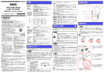
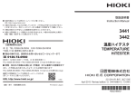
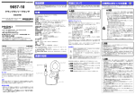
1
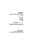
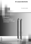
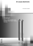
保守・サ-ビス
CT6500
クランプオンセンサ
CLAMP ON SENSOR
取扱説明書 / Instruction Manual
2012 年 10 月 改訂 2 版 Printed in Japan
CT6500A980-02 12-10H
• 短絡事故や人身事故を避けるため、本器は AC600 V 以
下の電路で使用してください。
• 対地間最大定格電圧は AC600 V です。大地に対してこ
の電圧を超える測定はしないでください。本器を破損
し、人身事故になります。
• 本器は、必ずブレーカの二次側に接続してください。ブ
レーカの二次側は、万一短絡があっても、ブレーカにて
保護します。一次側は、電流容量が大きく、万一短絡事
故が発生した場合、損傷が大きくなるので、測定しない
でください。
• 感電事故を防ぐため、使用中はバリア(障壁)より先を
触らないでください。
安全について
この取扱説明書には本器を安全に操作し、安全な状態に保つのに要する情報や
注意事項が記載されています。本器を使用する前に下記の安全に関する事項を
よくお読みください。
この機器は IEC 61010 安全規格に従って、設計され、試験し、安
全な状態で出荷されています。測定方法を間違えると人身事故や機
器の故障につながる可能性があります。また、本器をこの取扱説明
書の記載以外の方法で使用した場合は、本器が備えている安全確保
のための機能が損なわれる可能性があります。取扱説明書を熟読し、
十分に内容を理解してから操作してください。万一事故があっても、
弊社製品が原因である場合以外は責任を負いかねます。
安全記号
使用者は、取扱説明書内の
マークのあるところは、必ず読み注意す
る必要があることを示します。
使用者は、機器上に表示されている
マークのところについて、取扱
説明書の
• 本器をぬらしたり、ぬれた手で測定しないでください。
感電事故の原因になります。
• 最大入力電流を超える入力はしないでください。発熱による本器
の破損や短絡・感電事故の原因になります。
• ケーブルの被覆が破れたり、金属が露出していないか、使用する
前に確認してください。損傷がある場合は、感電事故になるので、
お買上店(代理店)か最寄りの営業所にご連絡ください。
• 活線で測定するので、感電事故を防ぐため、労働安全衛生規則に
定められているように、電気用ゴム手袋、電気用ゴム長靴、安全
帽などの絶縁保護具を着用してください。
活線状態の電路に着脱できることを示します。
交流(AC)を示します。
取扱説明書の注意事項には、重要度に応じて以下の表記がされています。
操作や取り扱いを誤ると、使用者が死亡または重傷につながる危険性が極
めて高いことを意味します。
操作や取り扱いを誤ると、使用者が死亡または重傷につながる可能性があ
ることを意味します。
操作や取り扱いを誤ると、使用者が傷害を負う場合、または機器を損傷す
る可能性があることを意味します。
製品性能および操作上でのアドバイスを意味します。
規格に関する記号
欧州共同体閣僚理事会指令 (EC 指令 ) が示す安全規制に適合していること
を示します。
EU 加盟国における、電子電気機器の廃棄にかかわる法規制 (WEEE 指令 )
のマークです。
• 本器を落下させたり、衝撃を加えないでください。コアの突合わせ面
が損傷し、測定に悪影響を及ぼします。
• クランプコア先端部に異物等を挟んだり、コアの隙間に物を差し込ん
だりしないでください。センサ特性の悪化、開閉動作不具合の原因に
なります。
• コード類の被覆に損傷を与えないため、踏んだり挟んだりしないでく
ださい。
• 断線による故障を防ぐため、ケーブルの付け根を折ったり引っ張った
りしないでください。
• コア部つき合わせ面にゴミなどが付着した場合は、測定に影響がでま
すので、柔らかい布で軽く拭き取ってください。
• トランスや大電流路など強磁界の発生している近く、また無線機など強電界
の発生している近くでは、正確な測定ができない場合があります。
• 位相特性が悪いため電力測定用途には使えません。
本器の故障、事故の原因になりますので、以下のような場所には設置しないでください。
本器は CAT III に適合しています。
測定器を安全に使用するため、IEC61010 では測定カテゴリとして、使用する場所によ
り安全レベルの基準を CAT Ⅱ~ CAT Ⅳで分類しています。
はじめに
このたびは、HIOKI CT6500 クランプオンセンサ をご選定いただき、誠にありが
とうございます。この製品を十分にご活用いただき、末長くご使用いただくために
も、取扱説明書はていねいに扱い、いつもお手元に置いてご使用ください。
概要
本器は 500 A 定格の交流電流対応の電圧出力型クランプオンセンサです。電
力ラインを切り離すことなく、活線状態で交流電流の測定が出来ます。また、
操作も簡単なため、多方面での電流測定にご使用いただけます。
カテゴリの数値の小さいクラスの測
定器で、数値の大きいクラスに該当する場所を測定すると重大な事故につながる恐れがあり
ますので、絶対に避けてください。
カテゴリのない測定器で、CAT Ⅱ~ CAT Ⅳの測定カテゴリを測定すると重大な事故につなが
る恐れがありますので、絶対に避けてください。
使用上の注意
使用前の確認
点検
本器がお手元に届きましたら、輸送中において異常または破損がないか点検し
てからご使用ください。万一、破損あるいは仕様どおり動作しない場合は、お
買上店(代理店)か最寄りの営業所にご連絡ください。
1
直射日光があたる場所
高温になる場所
腐食性ガスや爆発性ガスが
発生する場所
水、油、薬品、溶剤など
のかかる場所
多湿、結露するような場
所
強力な電磁波を発生する場
所
帯電しているものの近く
ホコリの多い場所
誘導加熱装置の近く(高周
波誘導加熱装置、IH 調理器
具など)
機械的振動の多い場所
外形寸法
約3 m
約 78W
質量
付属品
製品保証期間
約 360 g
取扱説明書
1年
使用前には、保存や輸送による故障がないか、点検と動作確認をしてから使用
してください。故障を確認した場合は、お買上店(代理店)か最寄りの営業所
にご連絡ください。
2
× 152H × 42D mm (突起物含まず)
f.s.: 最大表示値、目盛長 ( 一般的には、現在使用中のレンジを表します )
rdg.: 読み値、表示値、指示値 ( 現在測定中の値、測定器が現在指示している値を表します。)
各部の名称
CT6500 は電圧出力型クランプセンサです。
クランプコア
BNC コネクタ
バリア
ケーブル
測定方法
始業前点検
使用前には、保存や輸送による故障がないか、点検と動作確認をしてから使用
してください。故障を確認した場合は、お買上店 ( 代理店 ) か最寄りの営業所
にご連絡ください。
点検項目
対処方法
クランプ部にひび割れや破損はないですか?
損傷がある場合は、感電事故の原因にな
被覆が破れたり、金属が露出していませんか? りますので、使用しないでください。
コネクタ部およびセンサ側の根元部分が断線し お買上店 ( 代理店 ) か最寄りの営業所
にご連絡ください。
ていませんか?
• BNC コネクタを引き抜くときは、必ずロックを解除してから、コネ
クタを持って引き抜いてください。ロックを解除せずに無理に引っ
張ったり、ケーブルを持って引っ張るとコネクタ部を破損します。
• 接続機器の電源が入った状態で、コネクタの抜差しをしないでくださ
い。接続機器およびセンサの故障の原因になります。
導体は必ず 1 本だけクランプしてください。単相(2 本)
、三相(3 本)を同時
にクランプした場合は測定できません。
仕様
確度は 23±5°C 80%rh 以下において 1 年間保証 , センサ部開閉回数 :1 万回まで
定格一次電流
出力電圧
振幅確度
本器を安全にご使用いただくために、また機能を十二分にご活用いただくため
に、次の注意事項をお守りください。
点検・保守
測定可能導体径
コード長
レバー
測定カテゴリについて
CAT Ⅱ:コンセントに接続する電源コード付き機器(可搬形工具・家庭用電気製品など)
の一次側電路
コンセント差込口を直接測定する場合は CAT Ⅱです
CAT Ⅲ:直接分電盤から電気を取
り込む機器(固定設備)
の一次側および分電盤か
らコンセントまでの電路
CAT Ⅳ:建造物への引込み電路、引
込み口から電力量メータお
よび一次側電流保護装置
(分電盤)までの電路
高度 2000 m まで , 汚染度 2, 屋内
安全性 EN61010
EMC
EN61326 (Class A)
φ46 mm 以下
適合規格
マークの該当箇所を参照し、機器の操作をしてください。
二重絶縁または強化絶縁で保護されている機器を示します。
CT6500
使用場所
• 本器の汚れをとるときは、柔らかい布に水か中性洗剤を少量含ませて、軽く
ふいてください。ベンジン、アルコール、アセトン、エーテル、ケトン、シ
ンナー、ガソリン系を含む洗剤は絶対に使用しないでください。変形、変色
することがあります。
• 故障と思われるときは、
お買上店
(代理店)
か最寄りの営業所にご連絡ください。
• 輸送中に破損しないように梱包し、故障内容も書き添えてください。輸送中
の破損については保証しかねます。
振幅周波数特性
導体位置の影響
最大入力電流
AC500 A
AC1mV/A
±1.5% rdg.±0.03%f.s.
(f.s. は 500 A, 50 Hz/60 Hz, コア中心にて)
40 Hz ~ 1 kHz ±5% 以内(振幅確度からの偏差)
±3% 以内(中心からの偏差)
600 A 連続(45 ~ 66 Hz, 周囲温度 50°C)
温度係数
耐電圧
±0.05%rdg./°C
使用温湿度範囲
AC5312 Vrms 15 秒間 ( 電気回路 - コア間 )
AC600 Vrms 以下 , 測定カテゴリ III
( 予想される過渡過電圧 6000 V)
0 ~ 50°C, 80%rh 以下 ( 結露しないこと )
保存温湿度範囲
-10 ~ 60°C, 80%rh 以下(結露しないこと)
対地間最大定格電圧
3
OK
BNC コネクタを接続する
BNC コネクタ溝
コネクタガイド
1. BNC コネクタの溝を、本体側のコ
ロック
ネクタガイドに合わせて差し込み、
右へ回してロックします。
2. クランプ部を開き、導体を 1 本だけ
中央にクランプします。
3. クランプコア部が確実に閉じてい
ることを確認します。
BNC コネクタを本体から取り外すときは、左に回してから、引き抜いてください。
4
Safety Symbol
In the manual, the
symbol indicates particularly important
information that the user should read before using the product.
The
symbol printed on the product indicates that the user
should refer to a corresponding topic in the manual (marked with
the
symbol) before using the relevant function.
CT6500
Indicates a double-insulated device.
CLAMP ON SENSOR
Instruction Manual
October 2012 Revised edition 2 Printed in Japan
CT6500A980-02 12-10H
Applicable Standards
Indicates that the instrument may be connected to or disconnected
from a live circuit.
Indicates AC (Alternating Current).
The following symbols in this manual indicate the relative importance of cautions and warnings.
Indicates that incorrect operation presents an extreme hazard that
could result in serious injury or death to the user.
Indicates that incorrect operation presents a significant hazard that
could result in serious injury or death to the user.
Indicates that incorrect operation presents a possibility of injury to
the user or damage to the product
Advisory items related to performance or correct operation of the
product.
Symbol for Various Standards
This symbol indicates that the product conforms to safety regulations set out
by the EC Directive.
• Before using the product, make sure that the insulation on the
cable is undamaged and that no bare conductors are improperly exposed. Using the product in such conditions could
cause an electric shock, so contact your dealer or Hioki representative for repair.
• To avoid electric shock when measuring live lines, wear
appropriate protective gear, such as insulated rubber gloves,
boots and a safety helmet.
• Be careful to avoid dropping the product or otherwise subjecting
them to mechanical shock, which could damage the mating surfaces of the core and adversely affect measurement.
• Keep the clamp jaws and core slits free from foreign objects, which
could interfere with clamping action.
• Avoid stepping on or pinching the cable, which could damage the
cable insulation.
• To avoid damaging the cables, do not bend or pull the cables.
• Measurements are degraded by dirt on the mating surfaces of the
clamp-on sensor, so keep the surfaces clean by gently wiping with
a soft cloth.
Safety
EMC
EN61010
EN61326 (Class A)
Measurable conducφ 46 mm (1.81”) or less
tor diameter
Cable length
Approx. 3 m (118.11”)
Dimensions
Approx. 78W x 152H x 42D mm
(3.07”W x 5.98”H x 1.65”D) (excluding protrusions)
Mass
Approx. 360 g (12.7 oz.)
Accessory
Instruction Manual
f.s.: maximum display value or scale length
rdg.: reading value (The value currently being measured and indicated on the measuring
product)
Parts Names
The CT6500 is a voltage-output type clamp on sensor.
Clamp jaws
BNC connector
Barrier
WEEE marking:
This symbol indicates that the electrical and electronic appliance is put on
the EU market after August 13, 2005, and producers of the Member States
are required to display it on the appliance under Article 11.2 of Directive
2002/96/EC (WEEE).
Measurement categories
The Declaration of Conformity for instruments that comply to CE mark
requirements may be downloaded from the HIOKI website.
Introduction
Thank you for purchasing the HIOKI CT6500 CLAMP ON SENSOR.
To obtain maximum performance from the product, please read this manual first,
and keep it handy for future reference.
Overview
The CT6500 are voltage output type clamp on sensors, which are applicable to
500 A AC current measurements. These sensors can be used to measure alternating current on a live power line without the need to cut the wire. Easy operation and connection make them useful for measuring alternating current and
power in various fields.
This product complies with CAT III safety requirements.
To ensure safe operation of measurement products, IEC 61010 establishes safety
standards for various electrical environments, categorized as CAT II to CAT IV, and
called measurement categories.
CAT II: Primary electrical circuits in
equipment connected to an AC electrical
outlet by a power cord (portable tools,
household appliances, etc.) CAT II covers directly measuring electrical outlet
receptacles.
CAT III: Primary electrical circuits of
heavy equipment (fixed installations)
connected directly to the distribution
panel, and feeders from the distribution panel to outlets.
CAT IV: The circuit from the service drop to the service entrance, and to the
power meter and primary overcurrent protection device (distribution panel).
Using a measurement product in an environment designated with a highernumbered category than that for which the product is rated could result in a
severe accident, and must be carefully avoided.Use of a measurement instrument that is not CAT-rated in CAT II to CAT IV measurement applications could
result in a severe accident, and must be carefully avoided.
.
Inspection and Maintenance
Initial Inspection
• When you receive the product, inspect it carefully to ensure that no damage
occurred during shipping. If damage is evident, or if it fails to operate according to the specifications, contact your dealer or Hioki representative.
Maintenance and Service
• To clean the product, wipe it gently with a soft cloth moistened with water or
mild detergent. Never use solvents such as benzene, alcohol, acetone, ether,
ketones, thinners or gasoline, as they can deform and discolor the case.
• If the product seems to be malfunctioning, contact your dealer or Hioki representative.
• Pack the product so that it will not sustain damage during shipping, and
include a description of existing damage. We do not take any responsibility
for damage incurred during shipping.
Safety
This manual contains information and warnings essential for safe operation of
the product and for maintaining it in safe operating condition. Before using it,
be sure to carefully read the following safety precautions.
This product is designed to comply with IEC 61010 Safety Standards, and has been thoroughly tested for safety prior to shipment. However, mishandling during use could result in injury or
death, as well as damage to the product. Using the product in a
way not described in this manual may negate the provided
safety features. Be certain that you understand the instructions
and precautions in the manual before use. We disclaim any
responsibility for accidents or injuries not resulting directly
from product defects.
1
Usage Notes
Follow these precautions to ensure safe operation and to obtain the
full benefits of the various functions.
Preliminary Checks
• Before using the product the first time, verify that it operates normally
to ensure that the no damage occurred during storage or shipping. If
you find any damage, contact your dealer or Hioki representative.
• To avoid short circuits and potentially life-threatening
hazards, never attach the product to a circuit that
operates at more than the 600 V AC.
• The maximum rated voltage between input terminals
and ground is 600V DC/AC. Attempting to measure
voltages exceeding 600V with respect to ground could
damage the product and result in personal injury.
• This product should only be connected to the secondary side of a breaker, so the breaker can prevent
an accident if a short circuit occurs. Connections
should never be made to the primary side of a
breaker, because unrestricted current flow could
cause a serious accident if a short circuit occurs.
• To avoid electric shock, do not touch the portion
beyond the protective barrier during use.
• To avoid electric shock, do not allow the product to get wet,
and do not use it when your hands are wet.
• Ensure that the input does not exceed the maximum input
voltage or current to avoid product damage, short-circuiting
and electric shock resulting from heat building.
2
• Correct measurement may be impossible in the presence of strong
magnetic fields, such as near transformers and high-current conductors, or in the presence of strong electromagnetic fields such as near
radio transmitters.
• Poor phase characteristics prevent use in power measurement applications.
• This product may cause interference if used in residential areas.
Such use must be avoided unless the user takes special measures to
reduce electromagnetic emissions to prevent interference to the
reception of radio and television broadcasts.
Avoid the following locations that could cause an accident or damage to the
instrument
Exposed to direct sunIn the presence of corrolight
sive or explosive gases
Exposed to high temperature
Exposed to water, oil,
Exposed to strong elecother chemicals, or soltromagnetic fields
vents. Exposed to high
Near electromagnetic
humidity or condensation
radiators
Exposed to high levels
Near induction heating
of particulate dust
systems
(e.g., high-frequency
induction heating systems and IH cooking
Subject to vibration
utensils)
Lever
Cable
Measurement Procedures
Pre-Operation inspection
Before using the instrument the first time, verify that it operates normally
to ensure that the no damage occurred during storage or shipping. If
you find any damage, contact your dealer or Hioki representative.
Diagnose and Solution
Check items
Is a clamp cracked or damaged?
Do not use if damage is present, as you could
receive an electric shock. Contact your dealer or
Is there a wire break in the connector or Hioki representative if you find any damage
sensor base?
Isn't the cladding of the test lead torn?
• When disconnecting the BNC connector, be sure to release the lock
before pulling off the connector. Forcibly pulling the connector without
releasing the lock, or pulling on the cable, can damage the connector.
• To prevent damage to the connected instruments and sensor,
never connect or disconnect a sensor while the power is on.
Specifications
Accuracy guaranteed for one year at 23±5°C (73±9°F), 80%RH or less.,
opening and closing of the sensor: maximum 10,000 times
Attach the clamp around only one conductor. Single-phase (2-wire) or
three-phase (3-wire) cables clamped together will not produce any reading.
Rated primary
current
500 A AC
Output voltage
1 mV AC/A
Amplitude accuracy
±1.5% rdg.±0.03%f.s.
(f.s.:500 A, 50 Hz - 60 Hz, at core center)
Amplitude frequency Within ±5% at 40 Hz - 1 kHz
characteristics
(deviation from amplitude accuracy)
Effect of conductor
position
Within ±3% (deviation from center)
Maximum input
current
600 A continuous (at 45 - 66 Hz, ambient temperature
50°C)
Temperature coefficient
0.05%rdg/°C
Dielectric strength
5312 V rms for 15 seconds (between electric circuit and core)
Maximum rated
voltage to earth
600 V rms or lower, Measurement Category III
(Anticipated Transient Overvoltage:6000 V)
Operating Tempera- 0 to 50°C (32 - 122°F), 80%RH or lower
ture & Humidity
(non-condensating)
Storage Temperature & Humidity
-10 to 60°C (14 - 140°F), 80%RH or lower
(non-condensating)
Operating Environment
altitude up to 2000 m (6562-ft.), Pollution Degree 2,
Indoors
3
OK
1. Engage the BNC connector
grooves with the connectorguide projections, and turn
the connector clockwise to
lock the components.
Connect the BNC connector.
BNC connector
Connector grooves
guide
Lock
2. Open the clamp and hold
only one conductor at the
clamp center with the current direction indicator pointing toward the load side.
To remove the BNC connector, turn the connector counterclockwise and pull it out.
3. Make sure the clamp core is
closed.
4