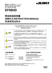
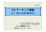
1
電動式テープフィーダ (ETF タイプ) Electric TAPE Feeder (ETF Type) 电动式带式供料器 (ETF 型) EF12FS/EF16FS/EF24FS 簡易取扱説明書 SIMPLE INSTRUCTION MANUAL 简易使用说明书 この度は、弊社の製品をお買い上げ頂きましてありがとうございました。 Thank you very much for purchasing a product of our company. 感谢您购买本公司的产品。 注意 CAUTION テープフィーダを安全に使用して頂くために、使用前に必ず本書をお読み頂き十分理解してください。 本書はお読みになった後、いつでも利用できるよう必ず所定の場所に保管してください。 この説明書は、テープフィーダの持つ特有の機能について説明してあります。 In order to ensure safe use of the TAPE FEEDER, be sure to read this Manual before using the machine. After reading this Manual, keep it at a fixed location so that it will be available at any time. This manual describes the functions specific to the tape feeder. 为了能让您安全地使用带式供料器,在您使用前,请一定仔细阅读本说明书。 阅读完本书之后,请妥善保管,以便能随时查阅。 本说明书仅就带式供料器的有关功能进行说明。 持ち運び時、テープフィーダを他のものに当てないように、また落下させないように注意してください。万が一衝撃を受けたときに は、異常がないかを必ず確認してください。 注意 CAUTION 危険,危险 DANGER また、フィーダを複数本同時に持ったり、保管時に平積みしたりなど、フィーダ同士が強く接触する事が無いように注意してください。 When you carry the feeder, be careful not strike it against any other thing or not drop it. If the tape feeder is subject to impact, check to see if it does not malfunction. Do not carry two or more feeders at the same time. Do not stack tape feeders flat during storage so that they cannot be in contact with one another tightly. 手持搬运时,注意不要使带状供料器碰撞他物,或掉落。万一受到冲击时,必须检查是否有异常。 此外,不要同时手持多个供料器,保管时不要叠放,要避免供料器互相强撞强压。 テープフィーダをマウンタ本体に取り付ける場合には、アッパーカバーが確実にロックされていることを確認してください。 アッパーカバーが開いていると重大な事故に繋がるおそれがあります。 To attach the tape feeder onto the main unit of a mounter, check to see if the upper cover is locked securely. If it is opened, it may cause a serious accident 在贴片机主机上安装带状供料器时,请检查上护罩确实已经锁好无误。 如若上护罩打开,可能引起严重事故。 産業装置ユニット カスタマーサポート部 〒206-8551 東京都多摩市鶴牧 2-11-1 〒564-0052 大阪府吹田市広芝町 10-28 オーク江坂ビルディング CUSTOMER SUPPORT DEPARTMENT ELECTRONIC ASSEMBLY SYSTEMS BUSINESS UNIT TEL:042-357-2298 FAX:042-357-2297 TEL:06-6380-2626 FAX:06-6380-2222 2-11-1, Tsurumaki, Tama-shi, Tokyo 206-8551, JAPAN PHONE: 81-42-357-2318 FAX: 81-42-357-2297 http://www.juki.co.jp/ Copyright © 2011-2012 JUKI CORPORATION All rights reserved throughout the world. ● 仕様,外観等は改良のためお断りなく変更することがあります。本書の内容を無断で転載、複写することを禁止します。 ● The specification and appearance may be changed without notice. ● 规格、外观等若有变更,恕不另行通告。未经许可,严禁私自转载或复印本书内容。 40093379 Rev01 1.はじめに / 1. Introduction / 1.前言 本書は電動式テープフィーダ(以下 ETF と表記)の操作方法を説明します。 ETF の機能の詳細につきましては、マウンタに添付される『取扱説明書 CD 内、 ETF 取扱説明書』を参照してください。 This manual explains how to operate an electric tape feeder (hereinafter referred to as "ETF".) For details, refer to " ETF Instruction manual" in CD provided with a mounter. 本书对电动式带式供料器(以下称 ETF)的操作方法进行说明。 ETF 功能的详细内容,请参见贴片机的附录『使用说明书 CD 内的 ETF 使用说明书』。 2.開梱 / 2. Unpacking / 2.拆包 1) ETF を包装袋から取り出します 1) Take out an ETF from a packing bag 1) 从包装袋里取出 ETF。 3) 「ロックリリースレバー」と「チャンバーリッド」の梱包テープを剥がします。 3) Peel off packing tapes for a "Lock release lever" and a "Chamber lid." 3) 拆开「解锁把」及「排带箱盖」的梱包带。 2) 「グリップクッション」を取り外します。 2) Remove a "grip cushion." 2) 抽出「手把垫」。 グリップクッション Grip cushion 手把垫 ロックリリースレバー Lock release lever 解锁把 チャンバーリッド Chamber lid 排带箱盖 梱包部品は大切に保管してください。 Keep packing parts in a safe place. 包装部件请妥善保存。 3.アンダーガイドブラケットの取り外し / 3.Removal of an "Under-guide bracket." / 3.拆除底部导架 ETF には出荷時に「アンダーガイドブラケット」が組み付いています。使用するエン ボステープの部品高さに応じて、「アンダーガイドブラケット」を取り外します。 An "Under-guide bracket" is mounted on an ETF when shipped. Remove it depending on a component height in an embossed tape to be used. 出厂时 ETF 安装有「底部导架」 。请根据使用的压纹带的原件高度, 拆除「底部导架」。 1) 「アッパーカバー」を開きます。 Open an "Upper cover." 打开「上护罩」。 2) 「セムスネジ」を緩め、「アンダーガイドブラケット」を取り外します。 Loosen a "sems screw" to remove an "Under-guide bracket." 拧松「西姆斯螺栓(带垫片螺栓)」,拆下「底部导架」。 ① 部品高さ:6mm 以下の場合: 「*1 キャリアテープ巻き癖確認方法」を参照してください。 ① Component height: In case of 6mm or less Refer to "*1 How to check if a carrier tape is curled." ① 元件高度:6mm 以下时: 请参见「*1 确认载带的卷带惯性方法」。 セムスネジ(M3) Sems screw (M3) 西姆斯螺栓(M3) ② 部品高さ:6mm を超える場合: 「アンダーガイドブラケット」を取り外してください。 ② Component height: In case of over 6mm: Remove an "Under-guide bracket." ② 元件高度:超过 6mm 时: 请拆下「底部导架」 。 アンダーガイドブラケット Under-guide bracket 底部导架 3) アンダーガイドブラケットを再組み付けする場合には『取扱説明書 CD 内、ETF 取扱説明書』の「アンダーガイドブラケット」を参照してください。 Refer to "An under-guide bracket" in ETF Instruction Manual in CD when re-mounting an under-guide bracket. 要重新组装底部导架时,请参见『使用说明书 CD 内、ETF 使 用说明书』的「底部导架」说明。 *1 キャリアテープ巻き癖確認方法 *1 How to check if a carrier tape is curled. *1 确认载带的卷带惯性方法 1) キャリアテープ先端から 150mm の位置を手で持ちます。 1) Hold a carrier tape at 150mm away from its end by hand. 1) 在距载带端头 150mm 位置上,用手夹住载带。 2) 90 度未満の場合、「アンダーガイドブラケット」を取り外します。 2) In case of less than 90 degrees, remove a "Under-guide bracket." 2) 90 度以下时,拆下「底部导架」。 取り外し例(90 度未満) Removal (Less than 90 degrees) 拆除示例(90 度以下) ・アンダーガイドブラケットの取り外し方法 ・How to remove an "Under-guide bracket." ・底部导架的拆除方法 取り外し不要例(90 度以上) Use as it is (90 degrees or more) 不需拆除示例(90 度以上) 1 アンダーガイドブラケットとねじは大切に保管してください。 Keep an under-bracket and screws in a safe place. 底部导架与螺栓,请妥善保存。 4. 仕様 / 4. Specifications / 4.规格 代表部品種 Typical component types 代表性元件类型 テープ種類 Tape types 带子类型 対応部品エンボス深さ Emboss depth of component 对应元件压花深度 外形寸法 Dimensions 外形尺寸 電源 Power supply 电源 部品搬送方式 Component transporting method 元件传送方式 電源電圧 Power supply voltage 电源电压 許容電流 Allowable current 额定电流 動作時環境条件 Operation environmental conditions 操作时的环境条件 12mm / 16mm / 24mm サイズ全般 注 1 12mm / 16mm / 24mm tape components in general 12mm / 16mm / 24mm 尺寸一般 注 1 エンボス Embossed 压花 17mm まで Up to 17mm 17mm 以下 全長=700 ㎜、高さ=335 ㎜ Entire length: 700 mm Height: 335 mm 全长=700mm,高度=335mm マウンタ本体から供給 Supplied with a mounter main unit. 从贴片机主机供给 Note 1 モータ駆動 Motor-driven 马达驱动 DC24V 1.8A 温度: 10℃~35℃ (精度保証 20℃~25℃) 湿度: 30%~80%RH (ただし、結露なきこと) 標高: 1,000m 以下 Temperature : 10℃ to 35℃ (Accuracy guaranty temperature 20℃ to 25℃) Humidity : 30% to 80%RH (No condensation) Altitude : 1,000m or less 温度: 10℃~35℃ (保证精度的温度 20℃~25℃) 湿度: 30%~80%RH (但不得有露水) 标高: 1,000m 以下 過電圧区分 Excessive voltage class 过电压区分 環境汚染度 Degree of environmental pollution 环境污染度 適合規格 Conformed standards 适合规格 区分Ⅰ : 過電圧が低いレベルに制限された回路からの供給(2次側低電圧回路等) Class I : Excessive voltage is supplied with the circuit whose voltage is limited to a low level (such as a secondary low voltage circuit). 区分 I : 过电压由限制为低级别的电路供给(2 级低电压电路等) 汚染度 3: 通常環境より汚染が進んだ環境(製造工場等) Degree of pollution 3: Environment whose pollution is worse than that of the normal environment (such as a manufacturing plant) 污染度 3: 比普通环境有所污染的环境(制造工厂等) ・機械指令 / Machinery Directive / 机械指令 : 98/37/EC+2006/42/EC ・評価規格 / Evaluation standards / 评价规格 : EN ISO 12100-1, EN ISO 12100-2, EN ISO 14121-1 ・EC EMC 指令 / EC EMC Directive / EC EMC 指令 : 2004/108/EC ・評価規格 / Evaluation standard / 评价规格 : EN 61000-6-4, EN 61000-6-2, EN 55011, EN 61000-4-2, EN 61000-4-3, EN 61000-4-4, EN 61000-4-6, EN 61000-4-8 注 1 : 部品サイズ及びテープ諸元については、JIS C0806-3(1999)、ET-7103(JEITA)に準拠します。 Note 1 : The component size and specifications of a tape that can be used with the tape feeder conform to JIS C0806-3 (1999) and ET-7103(JEITA). 注 1 : 元件尺寸及带子各部分标准,遵循 JIS C0806-3(1999),ET-7103(JEITA)。 警告 WARNING 注意 CAUTION テープフィーダまたはフィーダバンクに市販の電源などの機器を接続することは危険ですので絶対にしないでください。 Never connect any other device such as a commercially available power supply unit to the tape feeder or a feeder bank because it is highly dangerous. 切勿使用市场销售的电源器具接通供料器或供料器台架,否则会有危险。 各型式に適応した専用のテープフィーダを使用してください。 部品サイズ別の専用に設計されていますので、たとえ部品が流れても、正確な作動ができず、壊れるおそれがあります。 Use a tape feeder dedicated to each mounter model. Each tape feeder is designed exclusively for a certain component size. Therefore, if inappropriate components are set, it cannot operate properly and may be damaged even though those components are fed. 请使用适合各元件型号的专用带式供料器。 均为不同尺寸元件专用设计的,所以元件虽然流动,也有可能不能正确动作,有损坏的危险。 2 Japanese 5. テープの取り付け方法 1) フィーダをフィーダバンクのガイドレールに沿うように取り付け、「テープ交換ポジショ ン」まで引きだし、「段取り用コネクタ」をフィーダに接続します。 10) カバーテープを「テンショナシャフト」の上側、「テンショナローラ」の下側へ 通します。 段取り用コネクタ テープ交換ポジション テンショナシャフト テンショナローラ 2) 「アッパーカバーフック」を解除してから、「アッパーカバー前端部」を持ち上げます。 11) 「プルアイドラアーム」を指で押し、ギアの隙間へカバーテープをまっすぐ 差し込みます。 ②アッパーカバー前端部を持ち上げる プルアイドラアーム ①アッパーカバーフックを解除 3) フィーダの真下に来るようにテープリールを台車下のホルダにセットします。 小径リール(φ180 以下)を使用する際は、必ず仕切り板に「リール軸」を取り付 け、リール中心部の穴に入れます。 皿ねじ(M3) ○ × 12) 「操作パネル」より、フィーダのイニシャライズを行います。 ■スイッチと▼スイッチを同時押しすると、操作パネルに“0H”が点滅表示され、 イニシャライズ動作を開始します。 *イニシャライズ中に“E3”と表示された場合 ■スイッチを押し、 再度イニシャライズを実行してください。 リール軸 4) テープを「テープ挿入口」から「テープガイド」の下を通し、アッパーカバーの下まで 手で送り込みます。 テープ挿入口 注意 アッパーカバーを閉じていない状態でイニシャライズを実行する とテープの張力によってアッパーカバーが開きます。 イニシャライズ動作は、アッパーカバーのロックを確認してから、 行うようにしてください。 13) 供給位置に部品があることを確認します。 位置が悪い場合、▲(▼)スイッチで送り動作を行います。 テープガイド 供給位置マーク 5) 「アッパーカバー」を開いた状態で、テープをフレームとアッパーカバーの間に通します。 キャリアテープは、メインフレームの「ガイド」の下に差し込んでから、送り穴を「スプロ ケットホイール歯先」に差し込みます。 14) キャリアテープ出量がテープ排出口から 3mm 以下となるようにはさみで 切ります。 キャリアテープ出量 3mm 以下 スプロケットホイール歯先 ガイド 6) キャリアテープから剥がしたカバーテープを、アッパーカバーの「剥離スリット」を通し て上側へ引き上げます。 15) 「段取り用コネクタ」を取り外し、フィーダがフィーダバンクに突き当たるまで押 し込みます。その状態で、「ロックリリースレバー」を引き上げ、フィーダをロック します。 剥離スリット ロックリリースレバー 7) アッパーカバーを閉じます。カバーフックがしっかりとロックしていることを確認します。 またこのとき、キャリアテープの送り穴がスプロケットホイール歯先に入っていることを 確認します。 段取り用コネクタ 8) 「8. 送りピッチの設定変更」に従い、送りピッチの設定を確認してください。 9) カバーテープを「浮き上がり防止ガイド」の下部を通します。 浮き上がり防止ガイド 注意 3 EF12-24FS が EF08HD と隣接しているときは、EF12-24FS を「電動フィーダ用テープリール取付台」に装着してテープの交 換を行ってください。 Japanese 6. テープの取外し方法 7. カバーテープの廃棄方法 1) 「ロックリリースレバー」のロックを解除し、フィーダを「テープ交換ポジション」まで引き 出します。 1) 「チャンバーリッド」のつまみを手前に引き、カバーテープを回収します。 2) 「プルアイドラアーム」を指で押し、ギアの隙間からカバーテープを約 50mm 引き出 し、カバーテープをたるませた後、はさみで切ります。 カバーテープ廃棄口 チャンバーリッド 2) 生産中にカバーテープを回収する場合、カバーテープの廃棄口にて、 はさみでカバーテープを切ります。 カバーテープはプルアイドラアーム側の 位置で切ります。 プルアイドラアーム 注意 3) 「アッパーカバー」を開き、「テープ挿入口」からテープを引き抜きます。 カバーテープの廃棄時期は、リールを 1 本使い切ったとき、 または、チャンバーリッドが一段階開いたとき、上記の方法 でカバーテープを廃棄してください。 4) 「アッパーカバー」を閉じて、「アッパーカバーフック」をロックします。 8. 送りピッチの設定変更 ・操作パネル側の操作 ・ピールプレート側の操作 1) 「ピールプレート」を止めているねじを緩めます。 1) ■スイッチを 2 回押します。 2) 設定されている送りピッチが、操作パネルに点滅表示されます。 止めねじ 3) ▲スイッチ、または▼スイッチを押し、送りピッチを切り替えることができます。 4) 決定する時は、■スイッチを 2 回押します。 操作パネル表示 04 08 12 16 20 24 2) 「ピールプレート前端部」を「目安線」に合わせます。 送りピッチ 4㎜ 8㎜ 12 ㎜ 16 ㎜ 20 ㎜ 24 ㎜ 目安線 [mm] 送りピッチ EF12 EF16 EF24 4 ① ① ① 8 ② ② ② 12 ③ ③ ③ 16 20 24 ④ ④ ⑤ ⑥ 3) ねじを締めます。 *送りピッチ設定とピールプレートの位置は、必ず一致させてください。 *イニシャライズの後は、ピールプレートの位置を動かさないようにしてください。 9. 日常点検 日常点検項目 処置方法 点検調整箇所 アッパーカバー テープガイド 点検 テンショナアーム、シャフト プルアイドラアーム、ローラ スライドレール、ガイドレール、クランプ部 清掃 ピールプレート 前端部 ⑥⑤④③②① コネクタ部 スプロケットホイール 各部スプリング X ガイドピン(F/R) 剥離スリット テープガイド テンショナ部 点検項目 下面溝部に傷が無いか確認 汚れ、変形が無いか確認 アッパーカバー、カバーフックの開閉がスムーズか確認 テープ走行部の傷、汚れの付着がないか確認 アーム部の動作点検 ローラ部がスムーズに回転するか確認 ローラ部、シャフト部にゴミ、汚れが無いか確認 レール部に傷、異物が無いか確認 クランプ力が十分か確認 コネクタ周囲に素子などの異物が無いことを確認 歯底部に素子などの異物が無いことを確認 各部スプリングの外れ、欠損が無いことを確認 変形、摩耗の無い事を確認 剥離スリット部両面の粘着物等の清掃 テープ走行部全体の清掃 テンショナローラ、テンショナシャフトの清掃 毎日 毎週 頻度 毎月 6 ヶ月毎 リール装着時に点検 リール装着時に点検 リール装着時に点検 フィーダ装着時に点検 ○ ○ ○ ○ ○ ○ ○ ・異物の付着があった場合には、エアーガンで異物を除去してください。 ・汚れを除去する場合には、アルコールを含ませたウエスまたは綿棒で清掃してください。 ・アルコールは IPA(イソプロピルアルコール)またはエタノール(エチルアルコール)を使用してください。 ・エアーガンでゴミなどを吹き飛ばす場合、オイルミスト(ブロー時にエアに混じって噴霧されるオイル)の付着に注意してください。 部品の汚れ、カバーテープの巻取り不良の原因になります。 注意 ・テープフィーダは精密機械です。誤って衝撃あるいは無理な力が加わらないよう丁寧に扱ってください。誤って無理な力を加えた場合、または落下 した場合はピックポジションを確認してください。(ピックポジション調整は弊社サービスマンにご相談ください) ・ETF では、グリス、注油を必要としません。各ローラ部や、スプリング、スプロケットホイールにグリス、オイルを塗布し■スイッチを押し、再度イニシャライズ を実行してください。 4 English 5. How to Set a Tape 1) Along the guide rail of the bank, attach a tape feeder onto the feeder bank. Then, pull the tape feeder to the “tape replacement position,” and connect the “connector for changeover” to the tape feeder. Tape replacement position 10) Pass the cover tape over the tensioner shaft and under the tensioner roller. Connector for changeover Tensioner shaft Tensioner roller 2) After releasing the upper cover hook, raise the front end of upper cover 11) Push the pull idler arm with the finger, and insert the cover tape straight in the space of gear. Pull idler arm ②Raise the upper cover. Good No good ①Release the front end of upper cover hook. 3) Set a tape reel onto the holder located on the bottom of the trolley so that it can reach just under the tape feeder. When using the small diameter (180mm or less), install the reel shaft in the partition plate without fail, and put it in the hole in the center of the tape reel. 12) Initialize the tape feeder with the operation panel. Press the ■switch and the ▼switch at the same time, and “0H” flashes on the operation panel and the initialization begins. Countersunk screw (M3) When "E3" is displayed during the initialization, press the ■ switch to initialize the tape feeder again. Reel shaft 4) Feed the tape by hand from the tape loading slot under the upper cover after passing it under the tape guide. CAUTION Tape loading slot The upper cover opens due to the tension of the tape when you initialize the tape feeder with the upper cover not closed. Start initializing the tape feeder only after making sure that the upper cover is locked. 13) Check to see if a component is located at the component supply position. If it is not, press the ▲ (▼) switch to feed the tape. Component supply position mark Tape guide 5) Pass the tape during the frame and the upper cover with the upper cover opened. Insert the feed hole of the carrier tape into the teeth of the sprocket wheel after inserting it under the guide of the mainframe. 14) Cut the carrier tape with scissors so that the length of the carrier tape protruding from the tape ejecting slot can be 3mm or less. Length of the carrier tape protruded is 3mm Tooth of the sprocket wheel Guide 6) Pull up the cover tape peeled off from the carrier tape through the peel-off slit of the upper cover. 15) Disconnect the “connector for changeover,” and then push the tape feeder until it hits against the bank. In this condition, raise the lock release lever to lock the tape feeder. Peel-off slit Lock release lever 7) Close the upper cover. Make sure that the cover hook is firmly locked. Moreover, at this time, make sure that the feed hole of the carrier tape is in the teeth of sprocket wheel. Connector for changeover 8) Check the setting of the feed pitch according to Section 8. Changing a Tape Feed Pitch Setting. 9) Pass the cover tape under the bottom of the cover tape uplift prevention guide. Cover tape uplift prevention guide CAUTION 5 When EF12FS to EF24FS are next to EF08HD, attach EF12FS to EF24FS to the Feeder setup stand for Electric feeder before replacing a tape reel. English 6. How to Remove the Tape 7. How to Discard a Cover Tape 1) Release the lock lever to unlock it, and pull the tape feeder until it reaches the “tape replacement position.” 2) Push the pull idler arm with the finger, and pull the cover tape by approximately 50mm from the space of the gear. Loosen the cover plate, and cut it with scissors. 1) Pull the control of the chamber lid toward you, and extract the cover tape. Cover tape discarding slot Chamber lid 2) When extracting the cover tape during a PWB production, cut it with scissors at the cover tape discarding slot. Cut the cover tape at the position of the pull idler arm side. Pull idler arm 3) Open the upper cover, and pull out the tape from the tape loading slot. 4) Close the upper cover, and lock the upper cover hook. CAUTION When you use one reel completely or the chamber lid is opened by one stage, discard the cover tape by the above-mentioned method. 8. Changing a Tape Feed Pitch Setting - Operation on operation panel side 1) Press the switch twice. - Operation on the peel plate side 1) Loosen two screws fixing the peel plate. 2) The tape feed pitch currently set flashes on the operation panel. 3) You can change the tape feed pitch by pressing the S switch or the T switch. 4) Press the switch twice to fix the tape feed pitch. Fixing screws Display of the operation panel 04 08 12 16 20 24 2) Set the front end of the peel plate to the reference line. Tape feed pitch Reference line 4㎜ 8㎜ 12 ㎜ 16 ㎜ 20 ㎜ 24 ㎜ Peel plate front end ⑥⑤④③②① [mm] Feed pitch EF12 EF16 EF24 4 ① ① ① 8 ② ② ② 12 ③ ③ ③ 16 20 24 ④ ④ ⑤ ⑥ 3) Tighten the screws. *Be sure to match the feed pitch and the peel plate position. *Leave the peel plate position fixed after initialization. 9. Daily inspections Daily inspection item Corrective action Inspection Where to inspect Upper cover Tape guide Tensioner arm and shaft Pull idler arm and roller Slide rail and guide rail Clamp section Connectors Sprocket wheel Each spring X-guide pin (F/R) Peel-off slit Tape guide tensioner Cleaning – – Inspection item – Check to see if the groove of the bottom side of the upper cover does not have any scratch. – Check to see if the upper cover is neither stained nor deformed. – Check to see if the upper cover or the cover hook opens or closes smoothly. – Check to see if the tape travel section has neither scratch nor dirt. – Check operation of the arm section. – Check to see if the roller rotates smoothly. – Check to see if neither dust nor stain is stuck to the roller section. – Check to see if the rail section has neither scratch nor foreign substance. – Check to see if the clamp strength is enough. – Check to see if no foreign substance is around the connectors. – Check to see if no foreign substance is in the bottom side of each tooth. – Check to see if no spring is disconnected or missing. – Check to see if each guide pin is neither deformed nor worn out. – Clean any adhesive substance on both side of the peel-off slit – Clean the entire tape travel section – Clean the tensioner roller and the tensioner shaft. Every day Frequency Every Every week month Once a half a year Check it when a reel is attached on the feeder. Check it when a reel is attached on the feeder. Check these parts when a reel is attached on the tape feeder. Check these parts when the tape feeder is attached on a mounter. ○ ○ ○ ○ ○ ○ ○ If any foreign substance is stuck to any part, use an air gun to remove it. To remove stain, clean it off with alcohol-dampened waste cloth. – – – CAUTION – Use isopropyl alcohol (IPA) or ethanol (ethyl alcohol) as alcohol. When you blow off dust or a foreign substance with an air gun, be careful so that any oil mist (oil mixed in air when blown) cannot be stuck to any part. It may stain a part or cause a winding error of the cover tape. The tape feeder is a precision device. Handle it gently so that any impact cannot be made onto or any excessive force cannot be applied to it by mistake. If you happen to apply any excessive force to the tape feeder by accident, or if you drop it, check the component pick-up position. (Contact a service engineer for adjustment of the component pick-up position.) The ETF does not require any grease/lubrication. Do not apply any grease/oil to each roller, spring or sprocket. 6 Chinese 5.带子的安装方法 1) 将供料器沿着供料器台架的导轨安装好,拉到「换带位置」 ,把 「准备用插头」连接到供料器上。 换带位置 10) 使护罩带通过「张力轴」上侧,穿过「张力辊」下侧。 准备用插头 张力轴 张力辊 11) 用指头按下「拉杆空转臂」,把护罩带直着插入齿轮缝里。 拉杆空转臂 2) 打开「上护罩钩」后,提一下「上护罩前端部」。 ② 提一下「上护罩前端部」 × ○ ① 打开「上护罩钩」 3) 将卷筒安装到台车下面的架子使之在供料器的正下方。 使用小径卷筒(φ180 以下)时, 「卷筒轴」必须安装在隔板上, 插入卷筒中心部的孔里。 12) 在「操作面板」上,进行供料器的初始化。 同时按下■开关及▼开关,则操作面板的“0H”会闪烁显示, 开始初始化动作。 卷筒轴 *初始化中显示“E3”时, 请按■开关, 再次执行初始化。 平头螺钉(M3) 4) 用手送进带子,使之从「带子插入口」穿过「带子导块」下面, 到上护罩下面。 注意 在上护罩未关闭状态下进行初始化时,因带子的张力, 上护罩会打开。 请在确认上护罩确实关锁后,再进行初始化操作。 带子插入口 13) 请确认供给位置上有元件。 位置不适宜时,请按▲(▼)开关进行传送动作。 供给位置标记 带子导轨 5) 在「上护罩」打开的状态下,把带子穿过框架和上护罩之间。 把载带插入主框的「导块」下面,再把传送孔插入「链轮齿尖」上。 14) 从排带口出来的载带量,控制在 3mm 以下,多余的要用剪刀剪掉。 载带排出量控制在 3mm 以下 链轮齿尖 导块 6) 让从载带剥离下来的护罩带,穿过上护罩「剥离槽」拉上去。 剥离槽 15) 拔下「准备用插头」,把供料器推进去直到顶住供料器台车。在该 状态下,把「解锁把」提上去,锁住供料器。 解锁把 7) 关闭上护罩。确认护罩钩已经锁紧。同时,还要确认载带的 传送孔正好套进链轮齿尖。 准备用插头 8) 参照「8. 传送间距设置的变更」的说明,检查一下传送间距设置。 9) 让护罩带穿过「防止浮动导块」下面。 防止浮动导块 注意 7 若 EF12-24FS 与 EF08HD 邻接时,请将 EF12-24FS 安装到「电动供料器用卷筒安装台」,再进行带子的更 换装。 Chinese 6.带子的拆卸方法 7. 护罩带的废弃方法 1) 打开「解锁把」的锁,将供料器拉出至「换带位置」。 1) 请将「排带箱盖」捏手向前拉,回收护罩带。 2) 用手指按下「拉杆空转臂」,从齿轮缝隙把护罩带拉出约 50mm, 令护罩带松弛后,用剪刀剪断。 护罩带废弃口 排带箱盖 2) 在生产过程中回收护罩带时,请用剪刀在护罩带的废弃口处剪断。 拉杆空转臂 在拉杆空转臂一侧的位置上把护罩带剪断。 注意 3) 打开「上护罩」,带子插入口」拔出带子。 用完一个卷筒后,或排带箱打开一层时,请按上述方法 废弃一次护罩带。 4) 关闭「上护罩」,锁好「上护罩钩」。 8. 传送间距设置的变更 ・ 操作面板的操作 ・剥皮盘的操作 1) 把固定「剥皮盘」的螺丝拧松。 1) 按2次■开关。 2) 操作面板上闪烁显示设置的传送间距。 3) 通过按▲开关、或▼开关,可以切换传送间距。 固定螺丝 4) 要确定时,按 2 次■开关。 操作面板显示 04 08 12 16 20 24 2) 把「剥皮盘前头部位」与「刻度线」对准。 传送间距 4㎜ 8㎜ 12 ㎜ 16 ㎜ 20 ㎜ 24 ㎜ 刻度线 剥皮盘前头部位 ⑥⑤④③②① [mm] 传送间距 4 8 12 16 20 24 EF12 ① ② ③ EF16 ① ② ③ ④ EF24 ① ② ③ ④ ⑤ ⑥ 3) 拧紧螺丝。 *设置的传送间距与剥皮盘的位置,必须一致。 *初始化后,切勿移动剥皮盘的位置。 9.日常检查 日常检查项目 处理方法 检查调整的部位 上护罩 带子导块 检查 张力臂、轴 拉杆空转臂、辊 滑轨、导轨、钳夹部 清扫 插头部 链轮 各部分弹簧 X 导针(F/R) 剥离槽 带子导轨 张力部 检查项目 检查下面沟部是否有伤痕 检查有无脏污、变形 检查上护罩、罩钩开关是否顺畅 检查带子的行走部位有无伤痕、脏污。 检查臂部的动作 检查辊部旋转是否顺畅 检查辊部、轴部有无垃圾、脏污 确认轨道部分无伤痕、异物。 检查钳夹力是否充足 确认插头周围没有元件等异物 确认齿底部没有异物 确认各部位的弹簧无脱落、缺损 确认没有变形、磨损 清扫剥离槽部分两面的黏着物等 全面清扫带子的行走部位 清扫张力辊、张力轴 毎日 毎周 频度 毎月 每 6 个月 安装卷筒时检查 安装卷筒时检查 安装卷筒时检查 安装卷筒时检查 ○ ○ ○ ○ ○ ○ ○ ・若附着有异物时,请用气枪吹除异物。 ・在清除沾污时,请使用沾有酒精的湿布或棉签进行清扫 ・ 酒精类请使用 IPA(异丙醇)或者乙醇。 ・ 用气枪吹扫杂物时,请注意油雾(在吹气时混入空气而喷出的油雾)附着。 油雾可能造成元件沾污,护罩带卷绕不良。 注意 ・ 带式供料器是精密机械。请仔细操作,避免误动作造成冲击、或施加过大的力。若不慎施加了过大的力,或者掉落时, 请再确认吸取位置。 (需要对吸取位置进行调整,请与弊公司服务人员联系) ・ 对 ETF,不需要涂抹润滑剂或者注油。请不要在各辊部分,以及弹簧、链轮齿上涂抹润滑剂,注油。 8