1
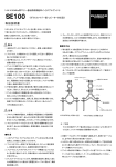
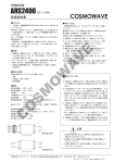
取扱説明書
同軸避雷器 防雨型 (雷サージ・プロテクター)
FL-332/FL-332S
■特
安全にお使いいただくために、
必ずお読みください。
¡ 使用者および周囲の人への危害や財産への損害を未然
に防ぎ、製品を安全に正しくお使いいただくために、
守っていただきたい注意事項を示しています。
¡ お読みになったあとは、大切に保管してください。
R警告
下記の記載事項は、これを無視して誤った
取り扱いをすると「使用者および周囲の人
が、死亡または重傷を負う可能性が想定さ
れる内容」を示しています。
¡ 雷が鳴り出したら、本製品やケーブルには、絶対に
さわらないでください。
感電の原因になります。
¡ 不安定な場所、高所など足場の悪い場所で設置工事
をしないでください。
落ちたり、すべったりして、けがの原因となります。
¡ 本製品の部品や工具類を高い所から落とさないでく
ださい。けがの原因になります。
¡ 設置や点検は、風雨、雷、雪などの天候の悪い日は、
危険ですので作業をしないでください。
落ちたり、滑ったりして、けがの原因になります。
¡ ガス管や水道管などにアースしないでください。
火災や感電、爆発、けがの原因になります。
¡ 本製品を分解しないでください。
分解されますと性能の保証ができなくなります。
R注意
下記の記載事項は、これを無視して誤った
取り扱いをすると「人が傷害を負う可能性
が想定される内容、および物的損害だけの
発生が想定される内容」を示しています。
¡ 電力保安用アースなどと共用しないでください。
また、ほかのアース回路とはなるべく隔離するよう
にしてください。
故障の原因になることがあります。
¡ 本製品は、誘導雷や静電気などのサージ電圧に対し
ては非常に効果的ですが、直雷による数万アンペア
の大電流に対しては効果ありません。
直雷対策に対しては避雷針を設置してください。
故障の原因になることがあります。
登録商標について
アイコム株式会社、アイコム、Icom Inc.、
イコム株式会社の登録商標です。
このたびは、FL-332/FL-332S(同
軸避雷器)をお買い上げいただきまして、
まことにありがとうございます。
ご使用の前に、この取扱説明書をよ
くお読みいただき、大切に保管してく
ださいますようお願い申し上げます。
は、ア
長
¡ 本製品には、一定電圧以上のサージ電圧が生じると、放
電して接地するガス封入式のサージ・アレスター素子を
内蔵していますので、極めて安全性に優れています。
¡ サージ・アレスターは、一定電圧で放電・復帰を何回
でも繰り返し動作します。
¡ 本製品は同軸管構造ですので、高周波特性が良く、広
帯域、低損失、低V. SWRです。
¡ この同軸避雷器は防雨型が特長です。
■ 外観図(パーツ名称)
ビス
¡付属の取り付け金具による設置例 (図1)
■ 設置方法
q 本製品は付属の取り付け金具やアース線を利用して、
取り付け例を参考に取り付けてください。
(図1、2参照)
w アースは付属のアース線(接続端子付き)を使用して、
反対側の先端を大地に埋設した避雷用アースに直接接
続してください。
e 本製品に接続するコネクターの部分をテーピングして
ください。
自己融着テープを元の長さの約1.5倍に引き伸ばしなが
ら巻き付けます。さらにその上にビニールテープでし
っかりと固定してください。(図3参照)
✩ 避雷用のアースは次の点に留意し、確実に行ってくだ
さい。
なお詳細はアースに関する専門書を参照していただく
か、専門の工事業者にご相談ください。
¡ 接地抵抗値はできるだけ小さくしてください。
¡ 銅板を大地に埋設するなどし、接地電極の表面積を
広くして、土壌との接触面積を大きくしてください。
¡ 地上高の高いアンテナタワーなどをご使用の場合
は、アンテナタワーやルーフタワーなどの基部をで
きるだけ太い線(断面積30mm 2 以上の銅線または
50mm2以上のアルミ線)で接地すると共に、タワー
上のアンテナ直下に同軸避雷器を取り付け、避雷器
のアースをタワーに通して接地するようにすると効
果的な避雷対策となります。
Sワッシャー
■ ブラケットでの固定方法
ブラケット
本体
■仕
様
¡周波数範囲
¡インピーダンス
¡定在波比
¡挿入損失
¡耐電力
¡放電開始電圧(500V/s)
¡衝撃波放電開始電圧(5kV/μs)
¡最大衝撃波電流耐量(8/20μs)
¡反復放電寿命耐量
(10/1000μs) 500A
¡絶縁抵抗 DC 100V
¡コネクター形状
¡外形寸法
:DC∼3000MHz
:50Ω
:1.2以下
:0.3dB以下
:200W PEP
:DC 230V ±20%
:1,000V
:10,000A
:500回以上
:10,000MΩ以上
:NJ型/NJ型
:78(W)×54(H)×26(D)mm
(コネクターも含む最大寸法)
¡重量
:約150g(取り付け金具を含む)
本製品が不用意に動かないようにブラケットを建物の
壁面などに市販の木ネジなどを利用して、確実に固定
してください。
(図2参照)
同軸ケーブルを接続しますから、しっかりとした壁面
もしくはそれに代わるものを選んで固定してくださ
い。
ブラケットは本製品を固定する以外の用途には使用し
ないでください。
本製品の性格上、落雷時の火災を考慮した場所を選ん
で設置してください。
¡付属の取り付けブラケットによる設置例 (図2)
Sワッシャー
Vボルト
ナット
ネジ
Sワッシャー
取り付け金具による
取り付け位置は、左
異なります。
右で90゜
取り付ける場所によ
り取り付けやすい方
を選んでご使用くだ
さい。
避雷器
取り付け位置
避雷器
アースへの接続は、アース線(接続端子付き)
をご使用ください。
¡接続例 (図3)
アンテナからの接続コネクター
が[NJ]タイプの場合
アンテナからの接続コネクター
が[NP]タイプの場合
コネクター接続部を自己
融着テープで巻き付け、
さらにビニールテープで
しっかりと固定してくだ
さい。
[NJ]
タイプ
[NP]
タイプ
[NP]
タイプ
[NP]
タイプ
[NP]
タイプ
本製品に付属
の同軸ケーブル
を使用
避雷器
アースへ
FL-332Sの場合
無線LANシステムへ
アンテナ側の
同軸ケーブル
避雷器
木ネジは付属していませ
ん。市販品の中から最適な
長さ (直径φ3mm) のも
のを選んでご使用くださ
い。
【ご注意】
壁面の内側にガス管、水道管、電気配線などがないこと確
認してください。
■ 付属品
¡取り付け金具:1
¡Vボルト
:1
¡Sワッシャー :2
¡自己融着テープ
:2
¡ナット
:2
¡アース線(接続端子付き) :1
¡変換コネクター
:1(FL-332Sのみ)
¡同軸ケーブル(約50cm):1
(接栓)FL-332:[NP]-[NP]、FL-332S:[NP]-[SMA-P]
マスト
547ー0003 大阪市平野区加美南1ー1ー32
変換コネクター
※本体への接続は、ご使用の無線LANシステムに同梱の取
扱説明書を参照してください。
※SMAタイプのアンテナコネクターを装備する無線LANシ
ステムの場合は、FL-332Sに付属の変換コネクターを、
外部アンテナ側の同軸ケーブルと避雷器のあいだに接続
してご使用ください。
■ Connections
■ Installation
INSTRUCTIONS
LIGHTNING SURGE PROTECTOR
FL-332/FL-332S
IMPORTANT
READ THIS INSTRUCTION MANUAL
CAREFULLY before installing the unit.
SAVE THIS INSTRUCTION MANUAL— This
manual contains important safety and operating
instructions for the FL-332/FL-332S.
CAUTIONS
Thank you for purchasing the FL-332/
FL-332S LIGHTNING SURGE PROTECTOR.
(Waterproof Type)
Please read the instructions thoroughly
before using the FL-332/FL-332S.
■ Features
❍ The built-in gas charge type surge arrester allows you
maximum safety and maintenance-free operation.
❍ Coaxial construction provides good RF characteristics,
wide frequency coverage, low insertion loss and VSWR.
❍ Rainproof construction.
■ Unit description
RWARNING: NEVER touch the unit and a coaxial
Screws
cable being connected, when there is thunder and lightning occurring.
Spring washers
1. Install the protector using with the supplied screws or
bracket as illustrated in the installation examples
Figure 1 and 2.
2. Connect the supplied grounding wire between the
protector and buried arrester grounding directory.
3. After the coaxial cable connections, cover the both
antenna connectors with rubber vulcanizing tape
first, then cover again with vinyl tape to fix them.
(See Fig. 3)
✩ Follow the subject listed below and refer to technical
book for lightning arrester grounding.
Minimizing the grounding resistance.
Maximizing the contacting area to the ground by
burying a copper plate, etc.
Install the protector just under the antenna when the
antenna has been installed on the top of the antenna
tower, or roof tower, etc., and grounded to the tower.
In this case, the tower should be grounded via at
least 30 square millimeters (113⁄16 square inches) thick
copper wire, or 50 square millimetres (2 square
inches) thick aluminum wire.
ï Using supplied screws
Pole
RWARNING: NEVER connect the grounding wire to
a gas, water or electric pipe, since the connection could
cause an explosion or electric shock.
Bracket
NEVER disassemble the unit. Otherwise the warranty
Protector unit
V-bolt
Screw
S-washer
CAUTION FOR INSTALLATION
NOTE
1. Do not share the grounding wire, and separate it as
much as possible from the other unit grounding line
to avoid malfunctioning.
2. Though the protector is designed to work well to
protect radio equipment from high surge voltage
caused by the static electricity or inductive lightning.
However, the unit CANNOT protect the equipment
from high current and voltage caused by a direct
lightning stroke.
Install a separate lightning conductor for the lightning
protection.
Icom, Icom Inc. and the
logo are registered
trademarks of Icom Incorporated (Japan) in the United
States, the United Kingdom, Germany, France, Spain,
Russia and/or other countries.
Pole S-washer
clamp
Nut
will not apply to this unit.
We are not responsible for any building breakage, any
damage resulting from a drop of FL-332/FL-332S from
a high place or unstable site or resulting from any
personal injury nor any accident in any other cases. If
FL-332/FL-332S is must be installed at such high place
or unstable site, be sure to consult an expert engineer.
(Fig. 1)
■ Specifications
● Frequency
range
● Impedance
● VSWR
● Insertion
loss
● Max. power input
● Start discharging voltage (500 V/s)
● Surge withstand voltage (5 kV/µs)
● Surge withstand current (8/20 µs)
● Repeated surge with stand
voltage (10/1000 µs) 500 A
● Insulating resistance 100 V DC
● Connector
● Outer dimensions
(incl. Type-N connectors)
● Weight (incl. Bracket)
: DC–3000 MHz
: 50 Ω
: Less than 1.2
: Less than 0.3 dB
: 200 W PEP
: 230 V DC ± 20%
: 1,000 V
: 10,000 A
: More than 500 times
: Over 10,000 MΩ
: Type-N (female; 50 Ω)×2
: 78(W)×54(H)×26(D) mm
31⁄16(W)×21⁄8(H)×1(D) in
: approx.150 g; 5.3 oz
■ SUPPLIED ACCESSORIES
• V-bolts ……………………………………………………1
• Pole clamp ………………………………………………1
• S-washers ………………………………………………2
• Nut ………………………………………………………2
• Grounding wire …………………………………………1
• Rubber vulcanizing tapes ………………………………2
• Coaxial cable ……………………………………………1
Using the supplied
grounding wire for
grounding.
installing
holes
Protector unit
When the antenna
has type-N male
connector.
When the antenna
has type-N female
connector.
(Fig. 3)
Cover the both type-N
connectors with rubber valcanizing tape
and fix them with a vinyl tape.
Type-N
female
Type-N
male
Type-N male
Type-N male
Protector
o
unit
To the ground
Type-N male
Use the supplied
coaxial cable.
For FL-332S
Antenna s coaxial cable
To the LAN unit
Connector converter
Protector unit
NOTE: When the LAN unit has an SMA type
antenna connector, connect the supplied connector
converter between the protecter unit and antenna’s
coaxial cable as described above.
The protector’s direction is selectable from horizontal
and vertical by installing mast clamp holes. Select the
desired direction for your installation convenience.
ï Using Bracket
the bracket on the flat and durable wall only.
(See Fig. 2)
● Use the supplied bracket for the protector installation
only.
● NEVER install the protector onto a wooden wall or put
an object, which easy to catch fire when lightning,
near the protector.
(Fig. 2)
The self-tapping screws
are not supplied.
Purchase the appropriate
screws locally.
● Install
3 mm; 1 8″ diameter
NOTE: Make sure the no gas, water pipes or house
electric wiring are running inside the wall.
(Connector; FL-332: [NP]-[NP], FL-332S: [NP]-[SMA-P])
• Connector converter (FL-332S only) ……………………1
1-1-32 Kamiminami, Hirano-ku, Osaka 547-0003, Japan
A-6110H-1G-w Printed in Japan
© 2003–2008 Icom Inc.