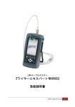
1
MODEL 550 CLAMP COUPLER
(Local Injector/Detector)
クランプカプラ
(ローカル・インジェクタ/ディテクタ)
INSTRUCTION MANUAL
取扱説明書
HR1030-13J-04 / 091216
** TABLE OF CONTENTS **
1. GENERAL INFORMATION ・・・・・・・・・・・・・・・・・・・・・・・・・・・・・・・・・・・・・・ 1
2. CONFIGURATIONS ・・・・・・・・・・・・・・・・・・・・・・・・・・・・・・・・・・・・・・・・・・・・ 1
3. SPECIFICATIONS・・・・・・・・・・・・・・・・・・・・・・・・・・・・・・・・・・・・・・・・・・・・・・ 2
4. OPERATING INSTRUCTIONS ・・・・・・・・・・・・・・・・・・・・・・・・・・・・・・・・・・・ 2
4-1.
4-2.
4-3.
Descriptions ・・・・・・・・・・・・・・・・・・・・・・・・・・・・・・・・・・・・・・・・・・・・・ 2
Operating Instructions ・・・・・・・・・・・・・・・・・・・・・・・・・・・・・・・・・・・・・ 3
Precautions ・・・・・・・・・・・・・・・・・・・・・・・・・・・・・・・・・・・・・・・・・・・・・・ 4
5. OPTIONAL ACCESSORIES ・・・・・・・・・・・・・・・・・・・・・・・・・・・・・・・・・・・・・ 5
6. REPAIRE SERVICE INFORMATION・・・・・・・・・・・・・・・・・・・・・・・・・・・・・・ 6
目
次
1.概 要 ・・・・・・・・・・・・・・・・・・・・・・・・・・・・・・・・・・・・・・・・・・・・・・・・・・・・・・・・ 7
2.構 成 ・・・・・・・・・・・・・・・・・・・・・・・・・・・・・・・・・・・・・・・・・・・・・・・・・・・・・・・・ 7
3.仕 様 ・・・・・・・・・・・・・・・・・・・・・・・・・・・・・・・・・・・・・・・・・・・・・・・・・・・・・・・・ 8
4.操 作 方 法 ・・・・・・・・・・・・・・・・・・・・・・・・・・・・・・・・・・・・・・・・・・・・・・・・・・
4-1 操作部の説明 ・・・・・・・・・・・・・・・・・・・・・・・・・・・・・・・・・・・・・・・・・・・・
4-2 使用方法 ・・・・・・・・・・・・・・・・・・・・・・・・・・・・・・・・・・・・・・・・・・・・・・・・
4-3 取扱上の注意 ・・・・・・・・・・・・・・・・・・・・・・・・・・・・・・・・・・・・・・・・・・・・
9
9
10
11
5.オ プ シ ョ ン ・・・・・・・・・・・・・・・・・・・・・・・・・・・・・・・・・・・・・・・・・・・・・・・・ 12
6.ア フ タ ー サ ー ビ ス ・・・・・・・・・・・・・・・・・・・・・・・・・・・・・・・・・・・・・・ 12
1. GENERAL INFORMATION
The 550 Clamp Coupler is a high-performance optical device that works as
a local detector and injector, inputting and outputting optical power at a
random point in a fiber without cutting.
By simply clamping a fiber, the 550 can detect light traveling through the
fiber and inject optical signals from the 550 itself into the fiber. While
inputting or outputting optical power, the 550 provides high coupling
efficiency.
Various kinds of optical connector can be used by attaching appropriate
connector adapters.
2. CONFIGURATIONS
1) For communication between a fiber end and a clamping point
Applicable fiber : SM fiber (coating dia.: 0.25mm)
Talk Set
:Model 430/450 Optical Talk Set
550
Talk Set
Talk Set
2) For power injection at a random point for fiber identification
By using a light source connected to the 550, light can be input in a fiber
without cutting.
550
1
3. SPECIFICATIONS
Wavelength
: 1310nm / 1550nm
Wavelength range
: 1300~1600nm
Applicable fiber
: Silica SM fiber (coating diameter: 0.25mm)
Coupling efficiency
: -17 ~ -23dB, -20dB TYP
(clear coating, 25+/-15℃)
Insertion loss
: 13dB or less (at 1310nm, 25+/-15℃)
19dB or less (at 1550nm, 25+/-15℃)
Return loss
: 40dB or greater
Optical connector
: SC (standard), FC, DIN, ST (optional)
Temperature/Humidity:
-10~+50℃, 80%RH or less
(non-condensing)
Dimensions
: 65(W)×230(H)×35(D)mm
Weight
: Approx. 300g
Accessories
: Carrying case ・・・・・・・・・・・・・・・・・・・・・・・・・・
Matching grease (190-M) ・・・・・・・・・・・・・・・・
Connector adapter (181-SC) ・・・・・・・・・・・・・
Swab・・・・・・・・・・・・・・・・・・・・・・・・・・・・・・・・・・
Instruction manual ・・・・・・・・・・・・・・・・・・・・・・
4. OPERATING INSTRUCTIONS
4-1. Descriptions
2
1
1
1
1
1
① Fiber clamp
Place a fiber in the V-groove D . When clamping a fiber, the fiber guides
A come down first to hold the fiber, and then the fiber clamper B falls to
clamp the fiber between the fiber clamper and the clamp base C .
② Clamp handle
This handle is to open and close the fiber clamp.
It moves slowly to avoid
clamping a fiber sharply.
③ Connector
The optical devices necessary for optical power input/output, such as an LD
light source, are connected to this connector.
④ Strap ring
This ring is used to hook a shoulder strap (optional).
⑤ Mode cutter
To prevent the light injected into the fiber from being effected by cladding
mode, put the fiber on this mode cutter making a circle along the groove
while clamping.
4-2. Operating Instructions
(1) Connecting external devices to the 550
Clean the ferrule face inside the connector and
attach
an
appropriate
connector
adapter.
Connect an external device to the connector using
a fiber cord.
(2) Putting matching grease (gel)
Press the clamp handle to open the fiber
clamp.
Put
some
matching
grease
(approx. 0.2ml) on the center of the clamp
base.
Too much grease may cause poor
coupling efficiency.
3
(3) Placing a fiber
Check the directions of the fiber for optical power input or output and place
the fiber in the V-groove following the arrows (OPT IN/OUT) below the fiber
clamp, which indicate the power input/output directions on the 550.
Then
release the clamp handle.
(4) Checking the fiber position
Make sure that the fiber is placed properly in the V-groove and held by the
fiber guides. Then pull the fiber 10mm to the right.
(5) Releasing the clamp handle
Release the clamp handle and the fiber clamper will come down to clamp
the fiber completely.
(6) Removing the fiber
When the operation is over, press the clamp handle to open the clamp
guides and the fiber clamper to remove the fiber.
grease on the fiber clamper with a cotton swab.
(Never use undiluted ethanol or acetone.)
Wipe out the matching
Then, release the clamp
handle.
4-3. Precautions
(1) To avoid damaging or cutting off the fiber, verify that the fiber is placed
properly in the V-groove before releasing the clamp handle.
4
(2) Keep the fiber clamp away from dust. If it is covered with dust, the
coupling efficiency will drop considerably.
Wipe off dust sometimes with a
swab moistened with ethanol diluted to less than 50%.
CAUTION: Never use undiluted ethanol or acetone.
(3) Please note that coupling efficiency varies depending on the type of fiber
coating or coating color, especially it is lower when clamping a fiber with
black coating.
(4) If the 550 does not perform well, change the clamping position of the fiber.
(5) The ferrule face inside the connector should be kept clean, otherwise loss
and reflection will increase here to effect the normal operation.
Therefore,
remove the connector adapter and clean the ferrule face with a swab
moistened with ethanol before use.
(6) To avoid damaging the ferrule inside the connector, always attach a
connector adapter to the connector.
Also attach a protection cap to the
connector adapter in order to protect it from dust.
5. OPTIONAL ACCESSORIES
Product Name
Model No.
Matching grease (gel)
Connector adapter
190-M
SC
181-SC
FC
181-FC
ST
181-ST
DIN
181-DIN
393H (1550nm, for SM fibers)
LD light source
392H (1310nm, for SM fibers)
395H (1310/1550nm, for SM fibers)
430 (Dynamic range: 45dB)
Optical talk set
450 (Dynamic range: 55dB)
Fiber ID
591, 590
Carrying bag
199-CBT
5
6. REPAIR SERVICE INFORMATION
When making requests for repair service, please bring the product to the
distributor or send it directly to the selling agency in Tokyo, Japan.
When sending it, always pack it in its original or equivalent packing material.
To ensure speedy and reliable repair, always include information as to the type of
failure and cause.
If required, always return accessories with the product.
Warranty
Graytechnos Co.,Ltd. warrants this product to be free from defects in material
and/or workmanship for one full year from date of shipment. During the
warranty period, we will, at our option, repair or replace any product which
proves to be defective.
For warranty service, send the product prepaid to the distributor or
Graytechnos Head Office in Tokyo, Japan. The repaired product will be
returned prepaid to Buyer.
Limitation of Warranty
This warranty shall not apply to defects resulting from any misuse,
misapplication, unauthorized modification, improper maintenance or operation
or storage outside of the environmental specifications.
Graytechnos makes no other warranties, expressed or implied, including
without limitation thereof, any implied warranty of merchantability or fitness for
a particular purpose.
Graytechnos shall not be responsible for any direct, indirect, special,
incidental or consequential damages.
― Specifications are subject to change without notice.
Graytechnos Co.,Ltd.
Kojima-build 2F, Ueno 1-6-5, Taito-ku, Tokyo, 110-0005 Japan
Phone:+81-3-5807-6081 Fax:+81-3-5807-6082
email:[email protected]
6
この度は当社のクランプカプラをお買い上げいただきありがとうございます。本器は、
すぐれた技術から創り出された信頼性の高い測定器です。はじめに、この「取扱説明
書」をよくお読みいただき、本器の操作に慣れてから、性能を充分に発揮されるよう、御
使用願います。
1.概要
本器は、光ファイバを使用した光通信線路において、光ファイバケーブル芯線の中
間点での光の入出射を無切断で行う装置です。
ファイバ内部に伝搬する光を、ファイバ芯線をクランプ部に挟み、ファイバを切断す
ることなく外部に取り出せます(ローカル・ディテクター)。また、クランプ本体側よりの
光信号をファイバ内部に入射することもできます(ローカル・インジェクター)。
本器は光入出射を高結合効率で行うことができます。
コネクタアダプタ交換により各種コネクタに対応できます。
2.構成
本器は以下のような構成で使用することが可能です。
・ファイバ線路の端点と中間クランプ点間の通話
トークセット430/450と併用しますと、ファイバ端点と中間点での通話が可能で
す(SM芯線、外形 250μ用)。
550
トークセット
トークセット
・中間点クランプによる通話
トークセット430/450と併用しますと、ファイバ中間点での通話が可能です(S
M芯線、外形 250μ用)。
550
トークセット
550
トークセット
7
・芯線判別用光源をファイバ中間点より入射
光源とクランプカプラを使用する事により、ファイバを切断することなく光入射が可
能です。
550
芯線判別器
光源
3.仕様
波長
: 1310nm/1550nm
使用可能光波長範囲
: 1300~1600nm
適合光ファイバ
: 石英ファイバ SM、芯線外形 250μ
結合効率※
: -17 ~ -23dB, -20dB TYP
(ファイバ被覆透明時, 25±15℃)
挿入損失※
: 13dB 以下 (1310nm, 25±15℃)
: 19dB 以下 (1550nm, 25±15℃)
反射減衰量
: 40dB 以上
光コネクタ
: 各種光コネクタに対応(SC, FC, ST, DIN)
使用温度
: -10~50℃ (80%RH 以下、ただし結露がないこと)
外形寸法
: 65(W)×230(H)×35(D)mm
重量
: 約 300g
付属品
: ・携帯用ハ-ドケ-ス
・マッチンググリスセット(190-M)
・コネクタアダプタ(181-SC)
・綿棒
・取扱説明書
×1
×1
×1
×1
×1
※ ファイバの種類、被覆色等によっては検出しにくい場合があります。
8
4.操作方法
4-1 操作部の説明
図4-1-1
① クランプ部
ファイバをV溝 D に入れ、クランプします。
クランプ時には先ずファイバガイド A が下降し、その後ファイバクランパ B が
下降し、クランプベース C との間でファイバを挟みます。
② クランプハンドル
クランプ部を開閉するレバーです。光ファイバ芯線に急激な力がかからないために、
ゆっくり動くようになっています。
③ コネクタ接続部
外部より光コネクタを接続します。ファイバ線路に光を入射するときはここにレーザ
ー光源の出力を接続します。ファイバ線路から光を出射するときはここに光出力が
得られます。
コネクタの種類に応じてコネクタアダプタを交換することができます。
④ ストラップ金具
携帯用のストラップ(別売)を取り付ける金具です。
⑤ モードカッター
入射した光のクラッド光の影響を避けたい場合は、クランプした後のファイバをこの
モードカッターの溝の中に半周か一周させる事により、クラッド光をカットすることが
できます。
9
4-2 使用方法
(1) 本器と外部機器との接続
コネクタ接続部のフェルール端面を清掃し、適切なコネ
クタアダプタを取り付けます(右図)。
コネクタ接続部に外部使用機器をファイバコードで接続
します。
(2) マッチンググリスを付ける
クランプハンドルを握ってクランプ部を開きます。
クランプベース中央部にマッチンググリスを少量
(わずかに盛り上がる程度)付けます。付けすぎると
結合効率が低下する場合があります。
マッチンググリス
(3) ファイバのセット
ファイバよりの光の出射またはファイバへの光の入射の方向を確認のうえ、本器
上部に表示された OPT IN/OUT の方向に合わせ、ファイバをV溝に挿入します。
ファイバ線路からの出射
ファイバ線路への入射
入射光
ファイバ線路
ファイバ線路
入射光
出射光
出射光
(4) 確認
ファイバがV溝に挿入されている事を確認し、その後、ファイバを右方向に10mm
程度引っ張ります。
(5) クランプハンドルを開放
ファイバクランパが下降してファイバを完全にクランプし、使用可能状態となりま
す。
10
(6) 終了
使用が終了したら、クランプハンドルを握り、ファイバクランパを開いてファイバを取
り出します。
その後クランプベースとファイバクランパに付着しているマッチンググリスを綿棒を
使用して拭き取ります。(注意:エタノール原液、アセトン等使用禁止)
(注意:エタノール原液、アセトン等使用禁止)
クランプハンドルを解放し、ファイバクランパを閉じておきます。
4-3 取扱上の注意
(1)ファイバの損傷や切断を避けるため、ファイバが確実にV溝に挟まっていることを確
認してからクランプハンドルを解放してください。
(2)クランプ部に汚れ、ほこりなどが付着すると、結合効率が著しく下がりますので、使
用時はほこり等が入らないように注意し、時々50%以下に希釈したエタノールを含
ませた綿棒等で拭き取ってください。
(エタノール原液、アセトンの使用は絶対に避けて下さい。)
(3)ファイバ芯線の種類や被覆の色によって結合効率が変わります。特に黒色の被覆
ではかなり結合効率が落ちます。
またファイバをクランプする場所によっても感知しにくい場合もありますので、その
時はファイバをクランプする場所を少し変えて試してください。
(4)コネクタ接続部のフェルール端面が汚れていると、この部分での損失や反射が大
きくなり、適切に使用できなくなります。使用前に必ずコネクタアダプタを一旦外し、エ
タノールを含ませた綿棒等でフェルール端面を清掃して下さい。
(5)コネクタ接続部のフェルールの損傷を避けるため、常にコネクタアダプタを取り付け
た状態にしておいて下さい。またほこり、汚れが付かないように、コネクタアダプタに
は保護キャップを取り付けて下さい。
11
5.オプション
本器と併用できる、次の様なオプション製品が用意されています。
品
名
型
マッチンググリスセット
コネクタアダプタ
LD 高出力ハンディ光源
名
190-M
SC
181-SC
FC
181-FC
ST
181-ST
DIN
181-DIN
393H (1550nm, SM ファイバ)
392H (1310nm, SM ファイバ)
395H (1310/1550nm, SM ファイバ)
光トークセット
430 (ダイナミックレンジ: 45dB)
450 (ダイナミックレンジ: 55dB)
ファイバ ID
591, 590
キャリングバック
199-CBT
6.アフターサービス
御使用中に万一故障した場合は、保証書の規定内容に従って修理いたします。
その場合は、お手数でもお買い上げ代理店または弊社に返送して下さい。返送する場
合はクッション材等で保護してからダンボール等の外箱に収納して、故障箇所、住所、
氏名、電話番号を明記し、保証書を同梱して下さい。
グレイテクノス株式会社
〒110-0005 東京都台東区上野 1-6-5 小島ビル 2F
電話:03-5807-6081 Fax:03-5807-6082
email:[email protected]
HR1030-13J-04 / 091216
12
- メ
モ -
保証書
グレイテクノス株式会社
保 証 規 定
1. 保証期間中に正常な使用状態で、万一故障等が生じました場合は無償で
修理いたします。
2. 本保証書は、日本国内でのみ有効です。
3. 下記事項に該当する場合は、無償修理の対象から除外いたします。
a. 不適当な取扱い使用による故障
b. 設計仕様条件等をこえた取扱い、または保管による故障
c. 当社もしくは当社が依嘱した者以外の改造または修理に起因する故障
d. その他当社の責任とみなされない故障
機種名
シリアル No.
550
保証期間
年
月
日より1ヶ年
お 客 様
お名前.
ご住所.
電話番号.
販売店
グレイテクノス株式会社
本社 〒110-0005 東京都台東区上野 1-6-5 小島ビル 2F
電話(03)5807-6081 FAX(03)5807-6082
様.