1
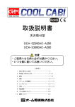
取扱説明書
側面取付型 ノンドレンタイプ
OCA-S350BCD-A200
OCA-S700BCD-A200
OCA-S1300BCD-A200
OCA-S2300BCD-A200
注意
・ご使用になる前に必ずお読みください。
・いつも側に置いてお使いください。
≪目次≫
1.安全に関するご注意……………………………2
2.各部名称・ドレン水蒸発機構の説明…………3
3.取付け方法………………………………………4~8
4.配線………………………………………………9~10
5.運転………………………………………………11~16
6. アラーム・安全機能……………………………17
7.メンテナンス……………………………………17~20
8.仕様………………………………………………21~23
9.保証期間…………………………………………24
10.フロン回収について……………………………24
11.廃棄について……………………………………24
1.安全に関するご注意
● このクーラは制御盤用クーラです。本来の目的以外では、絶対に使用しないでください。
● ご使用になる前に「安全に関するご注意」をよくお読みの上、正しくお使いください。
● 取扱説明書に示した注意事項は、安全に関する重大な内容を記載していますので必ず守ってください。
表示と意味は次のようになっています。
危険
取扱いを誤った場合、使用者が死亡または重傷を負う危険が切迫して生じることが想定される場合
注意
取扱いを誤った場合、使用者が損害を負う危険が想定される場合および物的損害のみが想定される場合
「図記号」の意味は次のようになっています。
絶対にしてはいけない「禁止」を意味します。
「回転物注意」を意味します。
気をつけていただく「注意喚起」を意味します。
「感電注意」を意味します。
必ず実施していただく「強制」を意味します。
危険
通電中は端子台に触らないでください。
注意
通電中は前面カバーを外さないでください。ファン回転部に指や異物を入れないでください。
作業は電源を切り、ファンが停止してから行ってください。
→ケガの原因になります。
屋外での使用はできません。
引火性ガス、腐食性ガス、油煙、絶縁を悪くするチリ等が発生または充満する場所では使用できません。
→寿命の低下、損傷の原因になります。
振動・衝撃のある場所では使用できません。
本体の改造・修理は絶対にしないでください。また、修理をする場合はメーカにご相談ください。
冷却回路に密封されている冷媒や油は、環境保護のため専門的な処理が必要です。
廃棄処理をする場合、必ず専門の処理業者によって処理をしてください。
クーラを設置する際、必ず周囲は円滑な空気循環が確保されている場所に設置または取付けてください。
→冷却能力が低下します。
クーラを運搬する場合、必ず傾斜させないで垂直になる様に運搬してください。
また、制御盤に取付けた状態での運搬は絶対にしないでください。
周囲温度が+20℃~+50℃で、周囲湿度が 85%RH 以下(非結露)の範囲で必ず使用してください。
クーラを保管する時は、必ず横および逆さにせず、周囲温度が+70℃を越すような環境では
保管しないでください。
クーラが納入された時、その梱包状態が損傷していないか確認してください。
→梱包の損傷は、クーラの故障の原因につながりますので、損傷を受けたクーラは絶対に
使用しないでください。
クーラを運転させた後に、クーラの取外しや移設、制御盤自体の移動等を行う際には、クーラ内部のドレン水
蒸発皿や最終ドレン皿に溜まっているドレン水をスポイトや布で吸い取って除去してください。
→ドレン水がクーラ本体内外にこぼれ落ちる可能性があります。
フィルタは、付属のものを使用してください。
→目の細かなフィルタを使用すると、放熱効率が下がり、冷却能力の低下・故障の原因になります。
クーラは、お子様や身体に何らかの障害を持つ方、又はクーラに関する知識の無い方のご使用はお避けください。
ただし、クーラに関する知識を有する物の監視の下、あるいはご使用に関する教育を受けている場合は、この限
りではありません。
2
2.各部名称・ドレン水蒸発機構の説明
2-1
各部名称(例:OCA-S1300BCD-A200)
エバポレータ
(盤内吸入口)
盤内ファン
(冷気吹出口)
操作パネル
前面パネル
盤外吸入口フィルタ
(盤外吸入口)
端子台
メンテナンスパネル
(盤外吹出口)
盤外ファン(内部)
2-2
ドレン水蒸発機構の説明(例:OCA-S1300BCD-A200)
注意
ドレン水蒸発シートを外して運転しないでください。
→クーラから水が飛散する可能性があります。
振動・衝撃のある場所で運転しないでください。
→振動・衝撃によって、ドレン水がクーラ本体内外にこぼれ落ちる可能性があります。
盤外ファン
ドレン水蒸発皿
蒸発
盤外空気
ドレン水蒸発フィン
ドレン水蒸発シート
コンプレッサ
コンデンサ
最終ドレン皿
ドレンパイプ
制御盤内で除湿されたドレン水は、以下の方法で蒸発されます。
① 制御盤内で除湿され発生したドレン水は、ドレン水蒸発皿に溜まります。ドレン水蒸発皿内部には、蒸発コイルが
あり、温められたドレン水が上部を通過する盤外空気により気化し、外部へ蒸発します。一方、蒸発コイルが冷たい
ドレン水により冷却されるため、冷凍回路の放熱効率が上がります。
② ドレン水蒸発皿で蒸発されないドレン水は、ドレン水蒸発フィンへ流れていきます。高温のドレン水蒸発フィンに
より、さらに温められたドレン水は、フィンを通過する盤外空気により気化し、外部へ蒸発します。
この蒸発の際に、ドレン水が周りから熱(気化熱)を奪うため、冷凍回路の放熱効率が上がります。結果として、
ドレン水が発生していない時に比べクーラ消費電力が最大 14%下がり、省エネ運転となります。
③ ドレン水蒸発フィンで蒸発されないドレン水は、ドレン水蒸発シートへ給水されます。コンプレッサの熱と
コンデンサの熱で温度上昇した盤外空気により気化し、外部へ蒸発します。
④ 盤内・盤外温湿度:35℃、85%RH 以下で発生するドレン水は 3 つの蒸発機構により蒸発されますが、
ノンドレン機能の仕様範囲外で発生するドレン水は、ドレンパイプより盤外へ排水される構造となっています。
3
3.制御盤への取付け方法
3-1
取付けに関するご注意
危険
クーラを制御盤へ取付けるときは、感電防止のため制御盤自体への電源供給を停止させてください。
注意
クーラの設置には、付属品以外のものは使用しないでください。
→故障やケガの原因になります。
取付穴(M6)に直接回転力が加わるような使い方はしないで下さい。
→取付穴にはカシメ袋ナットを採用しているため空転する恐れがあります。
取付面(パネルカット)は、規定の寸法で加工してください。
クーラの取付けは、図のように必ず水平・垂直(±2°)に取付けて
ください。
取付け後、水準器などを使用して傾きが無いことを確認してください。
→傾きがあると、ドレン水がクーラ本体内外にこぼれ落ちる可能性
があります。
また傾きがあることにより、ドレン水が蒸発機構に対して均一に
流れず、十分な蒸発性能を得られないことがあります。
クーラの設置は、円滑な空気循環を確保し、他のユニットまたは壁と
200mm 以上離して設置してください。
また制御盤内の空気循環が、必ず妨げられないようにしてください。
上記が守られないと、空気循環が悪くなり、冷却能力の低下や結露が
生じます。
クーラの使用電源は、必ず銘板に表記してある指定定格電圧を使用してく
ださい。
また、クーラへの電源取入れ口には、必ず適切なブレーカを介して接続し、
漏電による感電防止のため、アース線は必ず接地してください。
クーラの設置には電気工事が必要です。専門業者にご相談ください。
→配線等の設置工事に不備があると感電や火災の原因となります。
クーラを設置後、コンプレッサの保護のため、必ず 30 分以上経過してから通電、運転を開始してください。
設置する制御盤の気密性の確保(シーリング)を充分に行ってください。
→気密性が不充分であると結露が生じ、冷却効果が低下します。
制御盤へ取付面(パネルカット)を加工する際は、キリ粉が盤内機器に入らないよう布等でカバーしてから
作業を行ってください。
ショートサーキットについて
クーラ冷風吹出口付近に制御盤内の機器や障害物がある
場合、冷風がそれに当たりクーラの吸入口へ直接戻ってし
まうことがあります(ショートサーキット)
。
この場合、制御盤内に冷気が行き渡らず、盤内機器の故障
の原因となります。
また、クーラの運転にも負荷がかかり、過電流やクーラの
故障の原因となります。
クーラ運転時にショートサーキットが確認された場合は、
整風板の取付けや、攪拌用ファンを設置するなどして冷風
のショートサーキットを防止してください。
4
制御
機器
攪拌用
ファン
クーラ
冷風
整風板
3-2
取付け手順(※ 本機は、盤外取付専用機種です。)
①各機種の盤外取付けパネルカット図(P.6)に従って、開口部を取付面に加工してください。
②クーラに付属の取付ボルトを取付けてください。
(機種により本数が異なります。
)
③パッキン貼付け図(P.7)に従って、クーラ背面の取付ボルトの外側全周に付属のパッキンを貼ってください。
④取付面(パネルカット)に合わせてクーラを設置してください。
⑤盤内からワッシャ、ナットを使用して、確実に固定してください。
⑥制御盤の気密性を確保する為に、必要に応じてシーリングを行ってください。
⑦付属の「アラーム説明シール」を見やすい位置へ貼付けてください。
設置方法(例:OCA-S1300BCD-A200)
取付面
(パネルカット)
パッキン
ナット
スプリングワッシャ
ワッシャ
本体
アラーム説明シール
取付ボルト
注意
OCA-S700BCD、OCA-S1300BCD、OCA-S2300BCD-A200 は上面
にアイボルト取付用ナットが2箇所あります。アイボル
トを使用して吊り上げる場合には必ず2箇所を使用し
て均等に吊り上げてください。
1箇所のみで吊り上げるとクーラが故障、破損する可能
性があります。
5
アイボルト取付用ナット
●盤外取付けパネルカット図
<盤外から見た図>
OCA-S350BCD-A200
OCA-S700BCD-A200
OCA-S1300BCD-A200
OCA-S2300BCD-A200
6
●パッキン貼付け図
例:OCA-S350BCD-A200
例:OCA-S1300BCD-A200
パッキン
(斜線部分)
パッキン
(斜線部分)
3-3
ドレンホースの取付け
ドレンホースは以下の注意点を守り、正しく取付けてください。
注意
本機にはノンドレン機能が装備されているため、運転中に発生するドレン水はクーラ内部で
気化し、盤外への吹出し風により大気へ蒸発します。
ただし、以下の条件で使用した場合、ドレン水が蒸発されず、クーラ下部のドレンパイプより
排水されますので、クーラ設置時には必ずドレンホースを取付けてください。
排水されますので、クーラ設置時には必ずドレンホースを取付けてください。
・ノンドレン機能の仕様範囲外の温湿度条件で使用した場合。
(ノンドレン条件:周囲温度・盤内温度 35℃以下、周囲湿度・盤内湿度 85%RH 以下)
・ドレン水蒸発フィンの汚れ、ドレン水蒸発シートの汚れがひどい場合。
・盤外吸入口フィルタの詰まり、盤外ファンの劣化・故障などにより、蒸発機構の通過風量が低下
した場合。
・ドレンホースは折り曲げたり、巻いたりしないで
必ず直線になるように取付けてください。
・ドレンホースの先端は、曲げないでまっすぐ下に
向けてください。
・ドレンパイプにドレンホースを差し込む際は、
抜けないように根元まで差し込んでください。
ドレンホースの先端とドレンパイプの接合部が緩い
場合はホースバンドを使用し、確実な固定を行って
ください。
注意)ドレンパイプに無理な力を
加えないでください!
・ドレンホースの先端が必ずドレン水に浸からない長さにして
ください。
・ドレン水があふれ出ないように湿度の高い日などは必ずこまめに
捨ててください。
7
3-4
取外し・移設
注意
クーラを運転させた後に、クーラの取外しや移設、制御盤自体の移動等を行う際には、クーラ内部のドレン水
蒸発皿や最終ドレン皿に溜まっているドレン水をスポイトや布で吸い取って除去してください。
→ドレン水が溜まったまま残っていますと、クーラ本体内外にこぼれ落ちる可能性があります。
●OCA-S350BCD-A200、OCA-S700BCD-A200 の場合
①前面パネルを外してください。
(下部 1 箇所ネジ止め、上部引っ掛け構造となっていますので、ネジを外した後、
前面パネルを持ち上げるように外してください。
)
②メンテナンスパネルを外してください。
(4 箇所ネジ止め)
③ドレン水蒸発シートを外してください。
④ドレン水蒸発皿や最終ドレン皿に溜まっているドレン水をスポイトや布で吸い取って除去してください。
⑤クーラの取外しや移設を行ってください。
ドレン水蒸発皿
メンテナンスパネル
前面パネル
ドレン水蒸発シート
最終ドレン皿
●OCA-S1300BCD-A200、OCA-S2300BCD-A200 の場合
①メンテナンスパネルを外してください。
(OCA-S1300BCD :4 箇所ネジ止め、OCA-S2300BCD:8 箇所ネジ止め)
②ドレン水蒸発シートを外してください。
③ドレン水蒸発皿や最終ドレン皿に溜まっているドレン水をスポイトや布で吸い取って除去してください。
④クーラの取外しや移設を行ってください。
メンテナンスパネル
ドレン水蒸発皿
最終ドレン皿
ドレン水蒸発シート
8
4.配線
注意
・クーラの設置は、設置する国の規則に従ってください。
・電圧は銘板の表示電圧に従ってください。
・クーラの許容電圧は表示電圧の±10%です。電圧変動時も許容電圧内におさまるよう、電源容量に注意して
ください。
・アース(E)は必ず接地してください。
・通電前に使用電圧、配線、接地に問題がないことを確認してから通電してください。
4-1
配線方法(適合電線径
AWG24~12/0.2~2.5mm2)
①電線の被覆を 6~7mm剥いてください。
②マイナスドライバーにて端子台の「接続時押しボタン」を押し込んでください。
③電線差込口に電線を差し込んでください。
④マイナスドライバーを引いてください。
⑤電線が抜けないことを確認してください。
⑥圧着端子を使用する場合はフェニックス・コンタクト社製棒端子を使用してください。
◎端子台詳細図
●OCA-S350BCD-A200
●OCA-S700BCD-A200
●OCA-S1300BCD-A200
●OCA-S2300BCD-A200
a 接点 240V 1.5A ×2 抵抗負荷
※詳細は P.13、14 アラーム出力端子の割当
を参照してください。
a 接点 240V 1.5A ×2 抵抗負荷
※詳細は P.13、14 アラーム出力端子の割当
を参照してください。
接続時押しボタン
接続時押しボタン
電線差込口
電線差込口
L
N
E
1
2
3
R
AC200V アラーム出力
IN アース
S
T
E
1
2
3
三相 AC200V
アラーム出力
IN
アース
4-2 電気回路図
①OCA-S350BCD-A200、OCA-S700BCD-A200、OCA-S1300BCD-A200
(例:OCA-S1300BCD-A200) ※機種によりファンの数が異なります。
9
②OCA-S2300BCD-A200
4-3
過電流保護について
注意
クーラ専用の漏電ブレーカを必ず取付けてください。
→ 専用の漏電ブレーカを入れないと、万が一漏電が発生した場合、制御盤自体の漏電
ブレーカがトリップしてしまいます。
漏電ブレーカ
(クーラ専用)
ご使用のクーラに合わせて選定してください。
・クーラは電源投入時および冷却運転開始時に約 1 秒間の始動電流が流れます。この
始動電流に誤動作することがなく、その後の過電流を遮断するブレーカを選定して
ください。
・漏電ブレーカの定格感度電流は 30mA を目安にしてください。
10
クーラ
本体
5.運転
5-1
運転に関するご注意
注意
クーラを設置後、コンプレッサの保護のため、必ず 30 分以上経過してから通電、運転を開始してください。
コンプレッサの頻繁な ON/OFF は、故障の原因になり寿命を短くします。
1 時間に 6 回以上コンプレッサの ON/OFF を繰り返す様な運転は絶対しないでください。
頻繁な ON/OFF が起こる場合は、P.12 パラメータ設定のディファレンシャルの設定を大きくして
ください。
クーラの本体内に指を入れる事や、カバーを外したままでの運転は絶対しないでください。
→ケガの原因となります。
制御盤の扉を開放したままで、クーラの運転は絶対にしないでください。
→異常な結露および異常なドレン水の発生を招きます。また盤内に結露水が入る可能性があります。
ドレン水蒸発シートを外して運転しないでください。
→クーラから水が飛散する可能性があります。
5-2
操作パネル
Up ボタン
表示部(通電時:盤内温度表示)
運転ランプ(緑)
RUN
点灯:冷却運転中
消灯:冷却運転停止中
点滅:強制冷却運転中
Set ボタン
Up
Down
ALARM
Set
アラームランプ(赤)
Down ボタン
5-3
設定温度の変更
注意
設定温度は+35℃を基本とし、むやみに設定温度を下げないでください。
異常な結露および異常なドレン水の発生をまねきます。
①クーラの電源を投入してください。
(表示部に現在の盤内温度が表示されます。
)
②Set ボタンを押してください。
(現在の設定温度が点滅にて表示されます。
)
③Up、Down ボタンにてご希望の設定温度に変更してください。
(初期設定:35
(初期設定:35℃
設定温度範囲:30~
45℃)
:35℃ 設定温度範囲:30
:30~45℃)
④Set ボタンを押してください。
(設定温度が変更され、通常運転に戻ります。
)
5-4
強制冷却運転(クーラ点検時等にご使用ください。)
Up ボタンと Down ボタンを同時に 3 秒以上押してください。
運転ランプが点滅し強制冷却運転を開始します。「強制冷却運転時間パラメータ」で設定された時間動作した後、通常運転に
戻ります。
(強制冷却運転時間の初期設定は
)
(強制冷却運転時間の初期設定は 30 秒です。
11
5-5
パラメータ設定
通常、パラメータは設定を変更する必要はありませんが、変更の必要がある場合には下記の方法で変更してください。
○現在の盤内温度が表示されている状態から、Set ボタンを 3 秒以上押してください。
以下の順序でパラメータが表示されます。Set ボタンを押すことにより、次パラメータへ移動します。変
更したいパラメータを表示させ、Up ボタン・Down ボタンで設定値を変更し、Set ボタンを押すことによっ
てパラメータの変更が決定されます。
・ディファレンシャル
初期設定:5
初期設定:5℃
設定範囲:3~10℃
説明:(設定温度-ディファレンシャル)の温度に達した場合、コンプレッサが停止します。
注意:このパラメータを変更する際には、1 時間に 6 回以上コンプレッサが ON/OFF を繰り返さ
ない様な設定温度およびディファレンシャルに設定してください。
・強制冷却運転時間 初期設定:30
初期設定:30 秒 設定範囲:0~99 秒
Up Down ボタンを同時に 3 秒以上押したときに、強制冷却運転を行う時間です。
・盤内高温アラーム温度 初期設定:45
初期設定:45℃
45℃ 設定範囲:0~99℃
説明:盤内高温アラームが発生する温度です。
・アラーム用ディファレンシャル 初期設定:2
初期設定:2℃ 設定範囲:1~20℃
説明:盤内高温アラーム復帰用ディファレンシャルです。
(盤内高温アラーム温度-ディファレンシャル)の温度に達した場合、アラームが解除
されます。
・メンテナンスお知らせ機能 初期設定:0
設定範囲:0~99
初期設定:0
説明:メンテナンスの時期をお知らせする機能です。
0:
メンテナンスお知らせ機能を使用しない。
1~99: 1 を 100 時間としメンテナンス時期をお知らせします。
(制御基板内部では、1 時間単位にて時間をカウントしています。
)
例:99 設定⇒電源投入後 9900 時間後にメンテナンス時期をお知らせします。
(24 時間稼働の機械で約 412 日後)
・電源投入時の強制冷却運転の設定 初期設定:0
設定範囲:0、1
初期設定:0
説明:クーラの電源投入時に、強制冷却運転を行うかを設定します。
0:電源投入時に強制冷却運転しない。
1:電源投入時に強制冷却運転する。
・放熱異常時の冷却運転復帰方法の設定 初期設定:0
設定範囲:0、1
初期設定:0
説明:放熱異常アラーム発生時の復帰方法を設定します。
0:手動復帰(アラーム解除方法は P.17「6-1 (2)」を参照してください。
)
1:自動復帰(アラーム解除方法は P.17「6-1 (2)」を参照してください。
)
注意:自動復帰に設定した場合、冷凍回路内の放熱異常検出器が復帰すると冷却運転を
再開しますが、接点出力およびアラームコード表示はリセットされません。
放熱異常の原因が解消されないまま自動復帰を繰り返すと、クーラが故障する原因と
なりますので、お早めにメンテナンスを行ってください。
・メンテナンスお知らせ機能の出力設定[表示:Fo] 初期設定:1
設定範囲:0、1
初期設定:1
説明:メンテナンスお知らせ時間に達した時、アラーム出力端子で OPEN・CLOSE 切替えの有無を
設定します。出力端子の OPEN・CLOSE は次ページのアラーム出力端子の割当表を参考にし
てください。
0:切替えをしない。
1:切替えをする。
※0 に設定した場合、メンテナンスお知らせ時間になってもアラーム出力端子からは出力
されません。ただし、表示パネルにはE4と表示されます。
・アラーム出力端子の割当設定[表示:AS] 初期設定:0
設定範囲:0~3
初期設定:0
説明:アラームを検出すると、アラーム出力端子から出力されます。アラーム発生時のアラーム出
力端子の割当を設定することができます。
0:アラーム出力の監視
1:冷却動作とアラーム出力の監視
2:アラーム出力時、電源再投入の必要性の監視
3:アラーム発生時、冷却運転継続の監視
※アラーム出力端子の割当設定の詳細は P.13、14 を参照してください。
12
・アラーム出力端子の切替方法の選択[表示:Ao] 初期設定:0
初期設定:0 設定範囲:0、1
説明:出力端子の OPEN・CLOSE の切り替えを反転させることができます。
0:アラーム出力端子の割当設定の通りに出力されます。
1:0 の時と逆の動作をします。ただしAS:1 の時、端子 2-3 間には働きません。
※アラーム出力端子の割当設定の詳細は P.13、14 を参照してください。
・運転モードの設定[表示:rM] 初期設定:1
設定範囲:0~3
初期設定:1
説明:クーラの運転モードを設定します。
0:連続運転
1:省エネ運転①
※運転モードの詳細は P.15、16 を参照してください。
2:省エネ運転②
3:省エネ運転③
・省エネ運転③の冷却運転時間の設定[表示:t1]
初期設定:7
設定範囲:7~60 分
初期設定:7
説明:省エネ運転③に設定した時の冷却運転時間を設定します。
※rM:3 の時、表示されます。
・盤外ファン・コンプレッサの停止時間の設定 [表示:t2]
初期設定:3
設定範囲:3~10 分
初期設定:3
説明:コンプレッサが停止した後、再び動作できるまでの時間を設定します。コンプレッサの頻繁
な ON/OFF を防ぐ為、この間は設定温度以上でも冷却運転を開始しません。
・ソフトウェアバージョンの表示[表示:Sn]
説明:コントローラのソフトウェアのバージョンを表示します。変更はできません。
○設定が終了しましたら、Set ボタンを 3 秒以上押してください。現在盤内温度表示に戻り、設定が記憶されます。
○パラメータ変更を行っているとき、
30 秒間ボタンを押さなかった場合は設定が記憶されずに盤内温度表示にもどります。
再度パラメータ変更を行う場合は、Set ボタンを 3 秒以上長押ししてください。
5-6
アラーム出力端子の割当
アラームを検出すると、アラーム出力端子から出力されます。アラーム発生時のアラーム出力端子を設定することで
様々な動作の監視をすることができます。この設定はパラメータの AS と Ao を変更することで機能します。
クーラの電源投入前は端子 1-2 間、端子 2-3 間がともに OPEN となっています。
電源投入後、出力端子が切替るまでに 0.8 秒のタイムラグがあります。
(1)アラーム出力の監視[AS:0]
【初期設定】
各種アラームが発生した場合に出力が切り替わります。
(2)冷却動作とアラーム出力の監視[AS:1]
冷却動作を行っている場合と各種アラームの発生した場合に出力が切り替わります。
(3)アラーム出力時、電源再投入の必要性の監視[AS:2]
各種アラームが発生した場合、解除に電源を再投入する必要があるアラームと、自動復帰または手動復帰により解除す
るアラームを区別することができます。
(4)アラーム発生時、冷却運転継続の監視[AS:3]
各種アラームが発生した場合に冷却運転を継続するアラームと、停止するアラームで区別することができます。
13
アラーム出力端子の割当表[Ao
アラーム出力端子の割当表[Ao:
[Ao:0]
AS
クーラの状態
端子 1-2 間
端子 2-3 間
通常運転中
CLOSE
OPEN
各種アラーム出力 ON
OPEN
CLOSE
各種アラーム出力 ON
CLOSE
CLOSE
各種アラーム出力 OFF
OPEN
CLOSE
冷却動作と
各種アラーム出力 ON
CLOSE
OPEN
アラーム出力の監視
各種アラーム出力 OFF
OPEN
OPEN
E5,SE アラーム ON
CLOSE
CLOSE
E5,SE アラーム OFF
OPEN
CLOSE
E5,SE アラーム ON
CLOSE
OPEN
E5,SE アラーム OFF
OPEN
OPEN
E3,E5,SE アラーム ON
CLOSE
CLOSE
E3,E5,SE アラーム OFF
OPEN
CLOSE
アラーム出力時、
E3,E5,SE アラーム ON
CLOSE
OPEN
冷却運転継続の監視
E3,E5,SE アラーム OFF
OPEN
OPEN
0
機能
アラーム出力の監視
冷却動作中
1
冷却動作停止中
E1,E3,E4*アラーム出力 ON
2
アラーム出力時、
電源再投入の
E1,E3,E4*アラーム出力 OFF
必要性の監視
E1, E4*アラーム ON
3
E1, E4*アラーム OFF
※E4 アラームはFo(P.12):0 の時、出力されません。
アラーム出力端子の割当表[Ao
アラーム出力端子の割当表[Ao:
[Ao:1]
AS
クーラの状態
端子 1-2 間
端子 2-3 間
通常運転中
OPEN
CLOSE
各種アラーム出力 ON
CLOSE
OPEN
各種アラーム出力 ON
OPEN
CLOSE
各種アラーム出力 OFF
CLOSE
CLOSE
冷却動作と
各種アラーム出力 ON
OPEN
OPEN
アラーム出力の監視
各種アラーム出力 OFF
CLOSE
OPEN
E5,SE アラーム ON
OPEN
OPEN
E5,SE アラーム OFF
CLOSE
OPEN
E5,SE アラーム ON
OPEN
CLOSE
E5,SE アラーム OFF
CLOSE
CLOSE
E3,E5,SE アラーム ON
OPEN
OPEN
E3,E5,SE アラーム OFF
CLOSE
OPEN
アラーム出力時、
E3,E5,SE アラーム ON
OPEN
CLOSE
冷却運転継続の監視
E3,E5,SE アラーム OFF
CLOSE
CLOSE
0
機能
アラーム出力の監視
冷却動作中
1
冷却動作停止中
E1,E3,E4*アラーム出力 ON
2
アラーム出力時、
電源再投入の
E1,E3,E4*アラーム出力 OFF
必要性の監視
E1, E4*アラーム ON
3
E1, E4*アラーム OFF
※E4 アラームはFo(P.12):0 の時、出力されません。
14
5-7
運転設定
クーラは通電を開始すると、各運転モードで動作します。
初期設定ではクーラの設定温度 35℃、ディファレンシャル 5℃に設定してあります。
したがって、制御盤内の温度が 35℃でコンプレッサが動作、冷却を開始し、30℃で停止します。
運転モードは、連続運転、省エネ運転①、②、③の 4 モードから選択することができます。
運転の際の共通注意事項は以下となります。
・通電開始時に盤内の温度が盤内高温アラーム温度以上の場合には、AS、Aoの設定により、P.14 のアラーム出
力端子の割当表に従って、アラームランプが点灯します。
・冷却動作が停止してから一定時間(初期設定:3 分)は、制御盤内の温度が設定温度まで上昇しても冷却動作を行
いません。
(1)連続運転
盤内の温度が設定温度で運転し、ディファレンシャル温度で盤外ファン・コンプレッサが停止します。
盤内ファンは常時動作します。( )内の表示は初期設定です。
設定温度(35℃)
ディファレンシャル温度(30℃)
ON
盤外ファン・コンプレッサ OFF
盤内ファン
ON
OFF
(2)省エネ運転①【初期設定】
【初期設定】
盤内の温度がディファレンシャル温度よりも低くなると盤内ファンが 30 分に 1 回、30 秒間の送風運転を行います。この動
作を行うことによって制御盤内の熱だまりを防止することができます。冬場など冷却運転をしていない場合、盤内ファン
が間欠運転となることで省エネとなります。( )内の表示は初期設定です。
設定温度(35℃)
ディファレンシャル温度(30℃)
ON
盤外ファン・コンプレッサ OFF
盤内ファン
ON
OFF
【注意】
・盤内ファンは冷凍回路保護のため、冷却動作停止してから 5 分後に停止します。
・盤内の温度がディファレンシャル温度以上になると盤内ファンは連続動作します。
15
(3)省エネ運転②
盤内ファンの動作が冷却動作と連動します。
冬場など冷却運転をしていない場合、盤内ファンは停止することで省エネとなります。( )内の表示は初期設定です。
設定温度(35℃)
ディファンシャル温度(30℃)
ON
盤外ファン・コンプレッサ OFF
盤内ファン
ON
OFF
【注意】
・盤内ファンが停止する事で空気が循環されないことにより、局所的な温度上昇(熱だまり)が発生する可
能性があります。
・盤内ファンは冷凍回路保護のため、冷却運転停止してから 5 分後に停止します。
(4)省エネ運転③
盤内温度が設定温度以下になるが、ディファレンシャル温度まで下がらない場合に、冷却動作時間と停止時間を設け、一
定のサイクルでON・OFFさせる事により、省エネとなります。パラメータ設定t1とt2で冷却動作時間と停止時間
を設定することができます。( )内は初期設定です。
盤内高温アラーム温度(45℃)
設定温度(35℃)
ディファレンシャル温度(30℃)
盤外ファン・コンプレッサ
盤内ファン
ON
OFF
ON
OFF
※盤外ファン・コンプレッサ間欠運転時の冷却動作時間(7 分)
※盤外ファン・コンプレッサの停止時間(3 分)
【注意】
・コンプレッサを一定時間で強制的に動作停止させる為、盤内温度が設定温度よりも高くなる場合があり
ます。
また、盤内発熱量が大きい場合、盤内温度が盤内高温アラーム温度以上になる場合があります。
・盤内温度の過上昇防止のため、設定した冷却動作時間で設定温度まで下がらない場合は、盤内温度が設
定温度より低くなるまで冷却動作を継続します。
・盤内ファンは冷凍回路保護のため、冷却動作停止してから 5 分後に停止します。
・盤内の温度がディファレンシャル温度以上になると盤内ファンは連続動作します。
16
6.アラーム・安全機能
6-1
アラーム
(1)E1
E1:盤内高温アラーム
E1
盤内温度が 45℃(初期設定)になると、アラーム出力端子がAS、Aoの設定により(P.14 のアラーム出力端子の割当表参
照)出力する時、アラームランプが点灯します。表示部には現在の盤内温度とE1が交互に表示され、盤内温度の高温をお
知らせします。この時、冷却運転は停止しません。
盤内の温度が 43℃(初期設定)以下になると、アラームランプは消灯し、表示部には盤内温度のみが表示されます。
(2)E3
E3:放熱異常アラーム
E3
フィルタやフィンの目詰まり、ファンモータの故障等によりクーラが放熱異常状態になると、冷凍回路内の放熱異常検出器
が作動し、冷却運転を停止させます。この時アラーム出力端子がAS、Aoの設定により(P.14 のアラーム出力端子の割当
表参照) 出力する時、アラームランプが点灯します。表示部には現在の盤内温度とE3が交互に表示され、放熱異常をお知
らせします。
フィルタやフィンの清掃およびファンモータの交換を行った後、温度コントローラの Set ボタンを 3 秒以上長押しして、ア
ラームを解除してください。クーラは通常運転を再開します。
(3)E4
E4:メンテナンスお知らせ機能
E4
クーラの積算運転時間が、設定されたメンテナンスお知らせ時間に達すると、アラーム出力端子がAS、Ao、Foの設定
により(P.14 のアラーム出力端子の割当表参照)出力する時、アラームランプが点灯します。現在の盤内温度とE4を交互
に表示して、メンテナンス時期をお知らせします。この時、冷却運転は停止しません。
フィルタなどのメンテナンスをおこなった後、Set ボタンを押してアラームを解除してください。
メンテナンスお知らせ時間の設定を変更した場合は、それまでの積算時間はリセットされ 1 時間よりカウントされます。
(4)E5
E5:温度センサ断線アラーム
E5
何らかの原因で内部温度センサが断線した場合は、冷却運転を停止させます。アラーム出力端子がAS、Aoの設定により
(P.14 のアラーム出力端子の割当表参照) 出力する時、アラームランプが点灯します。表示部にはE5のみが表示されます。
クーラの電源を切り、メーカにご連絡ください。
(5)E8
E8:タイプエラー
E8
メーカにご連絡ください。
(6)SE
SE:システムエラー
SE
メモリの故障により、パラメータの設定値が正しく読み込めない時に発生します。表示部にはSEのみが表示されます。
クーラの電源を切り、メーカにご連絡ください。
6-2
安全機能
本製品の安全機能として、異常電流や異常温度では運転を停止します。
その時、アラームはE1、またはE3が発生します。
7.メンテナンス
注意
メンテナンスを行う時は、必ずクーラの電源を OFF にしてから作業を行ってください。
フィルタを交換する際は、弊社指定のフィルタを使用してください。
→目の細かなフィルタを使用すると、放熱効率が下がり、冷却能力の低下・故障の原因になります。
子供にクリーニングやメンテナンスの作業をさせないでください。
高圧洗浄機等を使用しての清掃はしないでください。
クーラの冷媒回路は製造時に必要な量の冷媒で満たされ、さらにリークテストおよびテスト運転をして出荷していますので、冷
媒回路のメンテナンスの必要はありません。
空気が汚れている環境でフィルタを使用している場合は、1週間に1度以上は点検・清掃をしてください。フィルタの
目詰まりにより冷却能力およびドレン水蒸発能力が低下します。また最悪の場合、コンプレッサに負荷が掛かり、クーラが停止
します。
17
7-1
盤外吸入口フィルタのメンテナンス
(例:OCA-S1300BCD-A200)
本体左側面のガイドよりフィルタを抜き出し、
清掃・交換を行ってください。
盤外吸入口フィルタ(白色)
◎交換用盤外吸入口フィルタ
フィルタ型式
適用機種
CF-S1(2枚入り)
CF-S8(2枚入り)
CF-S2(2枚入り)
OCA-S350BCD、OCA-S700BCD
OCA-S1300BCD
OCA-S2300BCD
7-2
盤外ファンの交換
(例:OCA-S1300BCD-A200)
盤外ファンが故障したときは、以下手順でファンの交換を行ってください。
① 盤外吸入口フィルタを外した後、右図のネジを4箇所外し、
盤外ファン取付板を取外してください。
② ファンコード、絶縁ゴム、アースコードを外し、ファン固定ネジと
ナットを外してください。
③ 盤外ファン取付板に交換するファンを取付けてください。
(※取付け方向は、盤外から吸込む向きで取付けてください。
)
盤外ファン取付板
④ ファン端子部分に絶縁ゴムをはめ込み、ファンコード、アース
コードを取付けた後、盤外ファン取付板をクーラへ取付けて
ください。
ネジ(4箇所)
(※ファンコードが取付け板と本体の間に挟み込まないように
注意してください。
)
アースネジ
ナット
アースコード
ファンコード
ファン固定ネジ
絶縁ゴム
◎交換用ファン
適用機種
盤内ファン型式
盤外ファン型式
OCA-S350BCD-A200
OCA-S700BCD-A200
OCA-S1300BCD-A200
OCA-S2300BCD-A200
FM-350BCDIN-200V
FM-700BCDIN-200V
FM-1300BCDIN-200V
FM-2300BCDIN-200V
FM-350BCDOUT-200V
FM-700BCDOUT-200V
FM-1300BCDOUT-200V
FM-2300BCDOUT-200V
18
7-3
盤内ファンの交換
(例:OCA-S1300BCD-A200)
盤内ファンが故障したときは、以下手順でファンの交換を行ってください。
① 盤内ファン取付板を固定しているネジ4箇所を外し、
盤内ファン取付板を取外してください。
(機種により盤内ファン取付板の形状が異なります。
)
② ファンコードを外し、ファン固定ネジとナットを外して
盤内ファン取付板
ください。
③ 盤内ファン取付板に交換するファンを取付けてください。
(※取付け方向は、盤内へ吹出す向きで取付けてください。
)
④ ファンコードを取付けた後、盤内ファン取付板をクーラへ
取付けてください。
(※ファンコードが取付け板と本体の間に挟み込まないように
注意してください。
)
交換用ファンの型式は(P.18)参照。
ネジ(4箇所)
ナット
ファンコード
7-4
ファン固定ネジ
蒸発シート、蒸発フィンのメンテナンス
ネジ(4箇所)
(例:OCA-S1300BCD-A200)
ノンドレン機能の仕様範囲内(盤内・盤外温湿度:35℃、85%RH 以下)
での使用にもかかわらず、ドレンホースからドレン水が排水される場合には、
ドレン水蒸発フィン、ドレン水蒸発シートの汚れが考えられます。
以下手順でメンテナンスを行ってください。
①
②
③
④
⑤
メンテナンスパネルを固定しているネジを4箇所外してください。
ドレン水蒸発フィンの汚れを、エアーブローなどで落としてください。
ドレン水蒸発シート固定金具を上へスライドさせて外し、蒸発シート
を取出してください。
ドレン水蒸発シートの汚れを取除いてください。
油汚れ、シートの劣化・硬化などが見られる場合は、新品の蒸発
ドレン水蒸発シート固定金具
シートと交換してください。
メンテナンス終了後、取外した逆の手順で蒸発シートおよび
メンテナンスパネルをクーラへ取付けてください。
メンテナンスパネル
ドレン水
蒸発フィン
◎交換用蒸発シート
蒸発シート型式
適用機種
CJ-S1(1枚入り)
CJ-S2(1枚入り)
CJ-S3(1枚入り)
CJ-S4(1枚入り)
OCA-S350BCD
OCA-S700BCD
OCA-S1300BCD
OCA-S2300BCD
エアーブロー
ドレン水蒸発シート
19
7-5
このような時には
現象
・電源が入らない。
何も表示していない。
原因
対策
a.ブレーカが切れている。
b.三相電源が正しく接続されていない。
(OCA-S2300BCD-A200 の場合)
a.ブレーカをONにしてください。
b.電源のR、S、T相が正しく接続されて
いるか、ご確認ください。
・盤内温度が上がりすぎる。 a.ブレーカが切れている。
a.ブレーカをONにしてください。
・冷風が出ない。
b.設定温度と盤内温度を確認してください。
b.設定温度より盤内温度が低い。
・盤内高温アラーム(E1) c.設定温度に冷却能力が追い付かない。
放熱異常アラーム(E3)
を表示している。
c.設定温度を上げてください。
またはクーラを冷却能力が大きい物に
換えてください。
d.周囲温度が高すぎる。
d.周囲温度が+50℃以上の環境では使用でき
ません。
e.盤内温度が高すぎる。
e.盤内温度が+45℃以上での使用はできませ
ん。
f.フィルタが汚れている。
f.フィルタを清掃してください。
g.盤外ファンが回っていない。
g.設定温度と盤内温度を確認してください。
ファンが故障している場合にはファンを
交換してください。
h.盤内ファンが回っていない。
h.P.11 強制冷却運転にて盤内ファンが回転
するか確認してください。
回転しない場合は、ファンを交換して
ください。
i.ショートサーキットがおきている。
i.P.4 を参考に、ショートサーキットを改善
してください。
・盤内温度が下がりすぎる。 a.設定温度を下げすぎている。
a.設定温度を上げてください。
b.内部回路または温度センサの故障。
b.メーカにご連絡ください。
・E5を表示している。
内部温度センサの故障。
メーカにご連絡ください。
・E8を表示している。
-
メーカにご連絡ください。
・SEを表示している。
メモリの故障
メーカにご連絡ください。
・ドレンホースからドレン水
が排水される。
a.盤内・盤外温湿度が仕様範囲を超えて
いる。
a.仕様範囲内で使用してくだい。
b.盤外風量が低下している。
b.P.18~19 を参考に、メンテナンスを
行ってください。
c.ドレン水蒸発フィン、ドレン水蒸発
シートが汚れている。
c.P.19 を参考に、メンテナンスを行って
ください。
・使用中に異常が生じた場合には使用するのをやめ、電源を OFF にしてメーカにご相談ください。
なお、ご相談される場合には、クーラの型式および製造 No.をお知らせください。
7-6
簡易点検方法について
フロン排出抑制法では、圧縮機の電動機出力が 7.5kW 未満の第 1 種特定製品については、
3 か月に 1 回の簡易点検が義務付けられています。
簡易点検の方法は、冷却運転中または強制冷却運転(P11. 5-4 強制冷却運転を参考)を行って、
盤内冷気吐き出し口より冷風が出ていることを確認してください。
20
8.仕様
8-1
標準仕様
型式
取付方法
冷却能力 ※1
定格電圧
定格
※2
消費電流 ドレン水発生時※3
最大
※2
始動電流
定格
※2
消費電力 ドレン水発生時※3
最大
※2
圧縮機 電動機出力
使用周囲温度 ※4
使用周囲湿度
騒音(A 特性)
温度設定範囲 ※4
ノンドレン温湿度条件
表示
OCA-S350BCD-A200
OCA-S700BCD-A200
300/350W
600/700W
単相
AC200V
1150/1300W
2100/2300W
50/60Hz
三相 AC200V 50/60Hz
1.4/1.4A
2.1/2.2A
3.5/3.6A
1.3/1.2A
2.1/2.1A
3.4/3.5A
3.4/3.7A
1.5/1.5A
2.4/2.6A
4.1/4.4A
4.0/4.4A
3.7/3.6A
6.1/5.9A
12.6/11.9A
14.6/14.8A
235/260W
390/425W
630/705W
975/1115W
225/240W
380/410W
625/695W
960/1150W
270/295W
455/510W
760/875W
1160/1390W
100W
250W
3.5/3.6A
400W
650W
+20℃~+50℃
85%RH 以下
約 62dB
結露無き事
約 65dB
約 65dB
約 68dB
+30℃~+45℃(初期設定:+35℃)
+35℃
85%RH 以下
盤内温度、アラームコード/運転ランプ/アラームランプ
盤内高温異常検出、放熱異常検出、温度センサ断線検出
メンテナンス時期お知らせタイマー、点検時強制冷却運転機能
外部出力
アラーム出力
耐振動性
振動数 10~150Hz 加速度 1.0G
保護等級
適合規格
OCA-S2300BCD-A200
側面取付型(盤外取付専用)
機能
冷媒
OCA-S1300BCD-A200
1a 240V 1.5A×2 出力(COMMON 共通)
内部循環
掃引サイクル 20 回
IP54 相当
EMC 指令
EN6100-6-2、EN6100-6-4 準拠
低電圧指令
EN60335-1、EN60335-2-40、EN62233
環境対応
RoHS
種類、名称
封入量
HFC R134a
HFC R407C
130g
190g
地球温暖化係数
355g
1430
620g
1770
塗装色
ベージュ(5Y7/1 相当)
制御基板ヒューズ定格
250V 1A
外形寸法 W×H×D(mm)
300×500×200
350×600×200
390×900×250
450×1150×250
本体質量
約 17.0kg
約 22.0kg
約 34.0kg
約 52.0kg
※1
※2
※3
※4
盤外温度および盤内温度が+35℃の場合の公称冷却能力です。
「定格」は盤外温度および盤内温度が+35℃の場合、「最大」は盤外温度+50℃、盤内温度が+35℃の場合の公称値です。
盤外温度および盤内温度 35℃、盤内湿度 85%RH 時に、ドレン水が最大量発生している時の公称値です。
温度範囲外では使用できません。
8-2
梱包内容
名称
クーラ本体
取付ボルト
ワッシャ
スプリングワッシャ
ナット
パッキン
ドレンホース
端子台
アラーム説明シール
取扱説明書
OCA-S350BCD-A200
OCA-S700BCD-A200
OCA-S1300BCD-A200
OCA-S2300BCD-A200
M6×35 ㎜:4 本
M6×35 ㎜:6 本
M8×35 ㎜:6 本
M6:4 個
M6:6 個
M8:6 個
M6:4 個
M6:6 個
M8:6 個
M6:4 個
M6:6 個
M8:6 個
1台
1 ロール
1 本(2m)
1個
1枚
1冊
21
8-3
外形寸法図
OCA-S350BCD-A200
<正面図>
<左側面図>
<右側面図>
<裏面図>
盤内
空気
冷気
盤外
空気
端子台
暖気
<下面図>
蒸発シート
盤外吸入口フィルタ(白)
4-M6 深さ 14
取付ボルト用
ドレンパイプ(外径φ12)
OCA-S700BCD-A200
<上面図>
2-M8 深さ 13
アイボルト用
<正面図>
<左側面図>
<右側面図>
<裏面図>
盤内
空気
冷気
端子台
盤外
空気
盤外吸入口フィルタ(白)
暖気
蒸発シート
<下面図>
4-M6 深さ 14
取付ボルト用
ドレンパイプ(外径φ12)
22
OCA-S1300BCD-A200
<上面図>
2-M8 深さ 13
アイボルト用
<左側面図>
<右側面図>
<正面図>
<裏面図>
盤内
空気
冷気
端子台
盤外
空気
暖気
<下面図>
4-M6 深さ 14
盤外吸入口フィルタ(白)
蒸発シート
取付ボルト用
ドレンパイプ(外径φ12)
OCA-S2300BCD-A200
<上面図>
2-M8 深さ 13
アイボルト用
<左側面図>
<正面図>
<右側面図>
<裏面図>
盤内
空気
冷気
盤外
空気
盤外吸入口フィルタ(白)
端子台
暖気
<下面図>
蒸発シート
6-M8 深さ 14
取付ボルト用
ドレンパイプ(外径φ12)
23
9.保証期間
メーカ出荷後、1 年間とします。
ただし、当社責任範囲外による故障は有償にて修理させて頂きます。
10.フロン回収について
盤用クーラには冷媒としてフロン類が使用されており、フロン回収・破壊法(平成 13 年 法律第 64 号)における第一種特定
製品として扱われ、フロン類の回収が必要な場合には、改正フロン回収・破壊法(平成 19 年 10 月施行)に基づいた処理が必
要となります。フロン回収・破壊法は、地球温暖化やオゾン層破壊の原因となるフロン類の大気中への排出を抑制するための
ものですので、必ず守ってください。
盤用クーラの廃棄に伴うフロン類の回収に関する注意事項とフロン回収・破壊法(抜粋)は下記の通りです。お分かりになら
ない時は、メーカにお問い合わせください。
■地球環境を保護するため、次のことが法律で定められていますので、必ず守って下さい。
・何人も、盤用クーラに封入されているフロン類をみだりに大気中に放出してはなりません。
■盤用クーラの所有者は、廃棄の際には、以下のことが必要になります。
①都道府県知事の登録を受けたフロン類回収業者にフロン類を引き渡すこと。
②その際には、法律に基づき書面を交付すること。
③フロン類の回収、破壊等に必要な費用を負担すること。
■冷媒番号及び封入量は、盤用クーラ本体に貼ってある製品銘板に記載してあります。
■盤用クーラは特定家庭用機器再商品化法(家電リサイクル法)の適用商品ではありません。
□所有者の管理責任
■機器の点検
盤用クーラは、3 か月に 1 回の定期点検が必要です。
■漏えい防止措置、修理しないままの充填の原則禁止
冷媒漏えいが確認された場合、可能な限り速やかに漏えい箇所の特定・必要な措置を実施する。
漏えいが確認された場合は、メーカまで速やかにご連絡下さい。
■点検等の記録
上記で行われた点検を含め、機器の修理、フロンガスの充填・回収の履歴を記録・保存します。
特に指定書式はありませんので、所有者の通常の点検記録簿に記入し保管下さい。
盤用クーラの修理、フロンガスの充填の必要がある場合は、メーカまでご連絡下さい。
11.廃棄について
盤用クーラを廃棄するときは、充てんされているフロンを回収した後、
「廃棄物の処理及び清掃に関する法律」に準拠し、必
ず専門の産業廃棄物処理業者に委託して処理してください。
本社/カスタマーサービスセンター
〒431-1304 静岡県浜松市北区細江町中川 7000-21
TEL:053-522-5572
FAX:053-522-5573
第 5 版 この取扱説明書の内容は 2015 年 4 月現在のものです。
24
Instruction Manual
Lateral Mounting Type
OCA-S350BCD-A200
OCA-S700BCD-A200
OCA-S1300BCD-A200
OCA-S2300BCD-A200
Caution
Please read this brochure carefully before use
and keep at hand for future reference.
≪Contents≫
1. Safety Precautions
・・・・・・・・・・・・・・・・・・・・・・・・・
2
・・・・・・
3
2. Part names and evaporation mechanism
・・・・・・・・・・・・・・・・・・・・・・・・・・・・・・・・・・
3. Mounting
4. Wiring
・・・・・・・・・・・・・・・・・・・・・・・・・・・・・・・・・・・・・
5. Operation
・・・・・・・・・・・・・・・・・・・・・・・・・・・・・・・・・・
6. Alarm/Safeguard
7. Maintenance
8. Specifications
9. Warranty period
10. Waste disposal
・・・・・・・・・・・・・・・・・・・・・・・・・・
4-8
9-10
11-16
17
・・・・・・・・・・・・・・・・・・・・・・・・・・・・・・・
17-20
・・・・・・・・・・・・・・・・・・・・・・・・・・・・・・
21-23
・・・・・・・・・・・・・・・・・・・・・・・・・・・
24
・・・・・・・・・・・・・・・・・・・・・・・・・・・・・
24
1. Safety precautions
- This product is an industrial cooling unit for control panel. Do not use this for any other purposes.
- Be sure to read these precautions carefully before starting operation for proper use.
- All the warnings and cautions described herein must be observed in order to use the product safely.
The marks and their meanings shown in this manual are as follows.
Danger
Improper handling is likely to lead to death or serious bodily injury.
Caution
Improper handling is likely to lead to bodily injury and/or property
damage.
The meanings of the symbols used in this brochure are as follows.
This is to drawn attention
Means “Strict prohibition”
for “Rotating body”
This is draw attention
This is to draw “Attention”
for “Electrical shock”
Means “Obligatory action”
Danger
Never touch the terminal board while the cooling unit is energized.
Caution
Never remove the front cover of the unit during operation. Do not put your
fingers or foreign matters into rotating part of the fan.
Always disconnect power and wait until the fans stop completely before starting
work. Failure to them can result in injury.
This product is for indoor use only.
This product should not be used where inflammable gas, corrosive gas, oil fumes
or dust which may affect insulation are contained in the air.
Failure to this may result in short life or damage of the unit.
Shocks and vibrations should be strictly avoided at the site of use.
Never tamper or repair the main body.
Please consult with your local supplier for repairing service.
Disposal of refrigerant and oil sealed in the cooling circuit should be dealt with
only by professional services.
Ensure smooth air circulation at the site of installation of the product.
Failure to this may degrade cooling performance of the unit.
Keep upright position during transportation without tilt.
Never transport it without dismounting from a control panel.
The atmosphere of the site of use should be within the temperature range from
+20℃ to 50℃ and humidity range 85%RH or less free from condensation.
The product should not be placed sideways or upside down during storage.
Storage temperature should not exceed +70℃.
Check for damage on packaging when the product is delivered.
Do not use the product if any damage is found. Any packaging damage may be a
cause of malfunction.
Avoid using other filters than enclosed.
Use of fine filters will cause efficiency loss in heat releasing which leads to
reduced cooling performance and/or breakdown of the unit.
This appliance can be used by children aged from 8 years and above and persons
with reduced physical, sensory or mental capabilities or lack of experience and
knowledge if they have been given supervision or instruction concerning use of
the appliance in a safe way and understand the hazards involved.
Children shall not play with the appliance.
2
2. Part names and evaporation mechanism
2-1 Part names (example : OCA-S1300BCD-A200)
Evaporator
(Suction port-inside)
Operation
panel
Suction port
filter - outside
(Suction
port-outside)
Internal fan
(Cool air output)
Front panel
Terminal board
External fan
(inside)
Maintenance panel
(Exhaust port- outside)
2-2 Evaporation mechanism (example : OCA-S1300BCD-A200)
Caution
Do not operate the unit without Evaporation Sheet.
Or, water scattering may occur.
The site of use should be free from shocks and vibrations.
If a cooling unit is exposed to shock and vibrationdduring operation,
drain water inside of it may leak out.
External fan
Outside air
Evaporation fin
Evaporation
Evaporation pan
Evaporation sheet
Compressor
Capacitor
Water pan
Drain pipe
(1) Condensate water generated inside an enclosure will evaporates as described below.Water
resulted from dehumidification that took place in an enclosure will pool in the Evaporation
pan.Evaporation coil is equipped in the pan to heat up the water.Heated water will vaporize by
the external air that passes above the pan and goes out.Meanwhile, the evaporation coil is
cooled by cold drain water, and thus heat radiation rate increases.
(2) Residue water in the Evaporation pan will flow to the Evaporation fin. By the high-temperature
Evaporation fin and the external air that passes through the fin, the water vaporizes into the
atmosphere.Meanwhile, such evaporation takes heat away from the surroundings and it brings
about higher heat radiation rate. As a result, electric consumption of the cooling unit is cut up
to 14%.
(3) As the final step, the Evaporation sheet absorbs the water not evaporated in the Evaporation fin
to evaporate it by the hot external air heated by the compressor and the capacitor.
(4) This product is designed to process condensate by the above 3-step evaporation mechanism on
condition that both internal and external temperature and humidity conditions are under 35
deg. C, 85% RH. Condensate water produced outside the above range is to be discharged
through the drain pipe.
3
3. Mounting
3-1 Caution
Danger
For prevention of electrical shock, power supply to the control panel should be
disconnected before installation work.
Caution
For installation, do not use any parts other than originally supplied ones.
Failure to this may result in injury or breakdown of the cooling unit.
In case screws are used for installation instead of the original bolts,
put a plate between the screw and the cap nut so as the direct torque not to
be transmitted. Or, the cap nut may cause slipping.
Cut out the mounting surface of the enclosure as specified in the drawing of page 8.
Enclosure Enclosure
COOLCABI must be placed horizontally and
COOL
perpendicularly within a tolerance of ±2⁰ in order
to keep stable operation of the unit and
CABI
to make a smooth drainage.
COOLCABI
Locate the unit so as to assure good ventilation
and distance of at least 200mm from the walls or
other units.
Also, there should be no hindrance to the air
circulation inside the control panel.
Failure to the above may result in poor cooling
performance or condensation.
200mm or more
Enclosure
COOLCABI
200mm
or more
Wall,
other units
R S
The supply voltage must be as specified on the rating
plate of the unit.
Electrical connection should be made via appropriate
Breaker for COOL
circuit breakers as shown in the right.
CABI
Leakage
Ground the wire without fail to prevent electrical
Earth
shocks
Electrical works required for installation of the unit must be done only
by specialists. Improper installation may result in electrical shocks or fires.
For protection of the compressor, wait at least 30 minutes after installation before
connecting power to start operation.
Hermetically seal the control panel all round.
Inferior sealing may cause condensation which lead to poor cooling efficiency.
Put covers on the components inside the enclosure to protect them from cutting
dust during installation work.
[Short circuit]
Electric components or other objects near the cool Control equipment
COOLCABI
air outlet may disturb cool air circulation. If the cool
air hit against them, it will directly return to the
suction port without being distributed to the whole
area in the enclosure. This causes not only troubles
of the components but may negatively affect
Cool
operation of the cooling unit which lead to
air
overcurrent and product failure.
In case such short circuit is found during cooling
Rectifying
operation, improve the environment by attaching
plate
rectifying plates or installing agitation fans as
Agitation fan
necessary.
4
3-2 Mounting procedure (This product is for external mounting only.)
(1) Process the mounting surface to cut out the openings in accordance with the respective
mounting cutout drawings in Page 6.
(2) Fit the enclosed bolts to the unit. The number of bolts differs depending on the model.
(3) Attach the enclosed packing on the rear side of the unit. Affix metallic packing outside
the fixing bolts as shown in the drawing of Page 7.
(4) Align the unit to fit the cutouts.
(5) Fit the washers and the nuts from inside the control panel and secure them.
(6) To ensure keep the panel interior airtight, caulk the gaps completely, if any.
(7) Apply the enclosed “Alarm description label” to an appropriate place where readily visible.
Illustrated mounting procedure (Ex. OCAOCA-S1300BCD
300BCD-A200)
Mounting surface
with cutouts
Nut
Packing
Spring washer
Washer
Alarm description label
Fixing bolt
COOLCAB
I
Caution
OCA-S700BCD-A200,
OCA-S1300BCD-A200 and
OCA-S2300BCD-A200 has two nuts
on top for installation of eyebolts.
Please lift up evenly using eyebolts
whenever lifting up a cooling unit.
Lifting up one side only may result in
breakdown or damage of the product.
5
Nut for eyebolt
installation
Cutouts for mounting < View from outside the panel>
OCA-S350BCD-A200
OCA-S700BCD-A200
OCA-S1300BCD-A200
OCA-S2300BCD-A200
6
Packing arrangement
Example : OCA-S350BCD-A200
Example : OCA-S1300BCD-A200
Packing
(Shaded area)
Packing
(Shaded area)
3-3 Attachment of drain hose
Attach the drain hose properly observing the following precautions.
Caution
This product is designed for drain free. Condensate water generated during
operation evaporates and released into the atmosphere blown by the outgoing air.
air.
In case it is used under the following
following conditions, however, condensate water is not
evaporated but discharged from the drain pipe located at the bottom of the
cooling unit. For this purpose, please attach the drain hose without fail at the
time of installation.
- When the unit is used outside the specified working
temperature/humidity range, i.e. temperatures not exceeding 35 deg.
C and humidity not exceeding 85%RH for both ambient and enclosure interior.
- When the evaporation fin or the evaporation sheet is dirty
- When passing air volume in evaporation mechanism declined due to some
trouble, like clogged suction port
on external side, deterioration or failure of
external fan, etc.
- Let a drain hose go directly downward without kinks and windings.
- The free end of a drain hose should be directly downward without bending.
- To prevent a hose from coming off, insert it deep enough to a drain pipe.
- In case the joint of a drain hose and a drain pipe is not tight enough,
use a hose band to fix the joint securely.
Enclosure
Enclosure
COOLCABI
COOLCABI
Attention: Do not put excessive force on drain pipe when working.
- Adjust the hose length so it end does not submerge
in the container.
- Empty the container frequently especially on
humid days.
7
WATER
3-4 Dismounting and relocation
Caution
In case a cooling unit is dismounted or relocated or the enclosure on which
a cooling unit is moved after installation and operation of the cooling unit,
eliminate water in the evaporation pan and water pan using a syringe or a wiping
cloth. Otherwise, such water may spill over from these pans.
●For OCA-S350BCD-A200 and OCA-S700BCD-A200
(1) Remove the front panel. The downside of the panel is fixed with a screw and
the upside is hooked. Unscrew first and then lift up the panel to remove.
(2) Detach the Maintenance panel by removing 4 screws.
(3) Absorb the water in the Evaporation pan and the Water pan with a syringe
or a wiping cloth.
(4) The cooling unit is now ready to be dismounted or relocated.
Evaporation pan
Maintenance panel
Front panel
Water pan
●For OCA-S1300BCD-A200 and OCA-S2300BCD-A200
(1) Detach the Maintenance panel
(OCA-S1300BCD:screwed at 4 places,OCA-S2300BCD:screwed at 8 places)
(2) Absorb the water in the Evaporation pan and the Water pan with a syringe or
a wiping cloth.
(3) The cooling unit is now ready to be dismounted or relocated.
Maintenance panel
Evaporation pan
Water pan
8
4. Wiring
Caution
- Please observe all the local regulations in installation of the cooler.
- Supply voltage should be as specified on the rating plate.
- Allowable power fluctuation is +/- 10% from the rated voltage. Pay attention
the maximum fluctuation should be stayed within this range.
- Make sure that grounding has been properly done.
- Before electrifying the unit, make sure again that there is no problem
in supply voltage, wiring connection and grounding.
4-1 Wiring procedure (Applicable wire range: AWG24 to 12 / 0.2 to 2.5m ㎡)
(1) Strip the wire by 6 or 7 mm.
(2) Push down the Push button with a flathead screwdriver.
(3) Insert a wire into the port.
(4) Release the screwdriver.
(5) Check that the wire is secured.
(6) For the application using crimp terminals, the bar terminals made by Phoenix Contact.
●OCA-S350BCD-A200
●OCA-S700BCD-A200
●OCA-S1300BCD-A200
●OCA-S2300BCD-A200
a contact, 240V 1.5A x2 resistance load
Note: For details, please refer to
the paragraph 5-6 in page 13,14
a contact, 240V 1.5A x2 resistance load
Note: For details, please refer to
the paragraph 5-6 in page 13,14
Push button for
connection
Push button for
connection
Wire port
Wire port
L
N
200VAC IN
E
1
2
R
3
Alarm output
S
T
E
1
2
3
3phase
Alarm output
200VAC IN
Earth
Earth
4-2 Circuit diagram
①OCA-S350BCD-A200、OCA-S750BCD-A200、OCA-S1300BCD-A200
(Example : OCA-S1300BCD-A200) ※The number of fans differs according to the model.
Control board
Terminal board
Fuse 250V 1A
L
N
E
CN4
CN6
Sensor
CN8
RY1
Overheat detector
CN3
OLP
Operating
condenser
CMP
Compressor
FM2
FM2
External fan x 2
9
1
2
3
Terminal
board
E
FM1
Internal fan
CN1
②OCA-S2300BCD-A200
Thermal relay
Terminal board
R
S
T
E
RST
Overheat Control board
detector
Fuse 250V 1A
CN4 Sensor
CN6
CN8
CA
RST BCA
R S T1
S R1
Magnetic
switch
Reverse phase
prevention relay
UVW
UVW
FM1 FM1
Internal fan x 2
3
1
Terminal
board
CN3 CN1
1
2
3
E
2
FM2 FM2 FM2 FM2
Compressor
External fan x 4
OLP
(Overload protector)
CMP
RY1
MG1
4-3 Overcurrent protection
Caution
Do not forget to fit an earth leakage breaker.
→ Failure to this may lead to tripping of the earth-leakage breaker for
the enclosure in the event of electric leakage.
Selection of a breaker should be made so as to fit the type of the cooler.
a. With the input of power supply, or with the start of cooling operation,
COOLCABI is subject to starting current for approx. 1 second. Therefore,
the selection of an earth leakage breaker should be made so as to assure
stable operation without affected by such current as well as providing
effective protection against possible overcurrent thereafter.
Earth leakage
breaker
b. For earth leakage breakers, use a reference value of 30mA
(For exclusive
for sensitivity rating as a guide of selection.
use of cooler)
COOL
CABI
10
5. Operation
5-1 Caution
Caution
For protection of compressor, wait at least 30 minutes after installation of
the unit and then turn on power to start operation.
Frequent switching on and off of a compressor may be a cause of trouble
and shorten its lifetime. Never repeat ON/OFF more than 5 times within an hour.
Turn up the differential value of the parameter setting (see Article 5-5) if frequent
on-off occurs.
Never put your fingers into the unit or uncover the unit during operation.
Failure to this may be a cause of injury.
Never operate COOLCABI leaving the control panel door open.
Failure to this may lead to excessive condensation and drainage volume as well as
creating the possibility to allow condensate to enter into the control panel interior.
Do not operate the COOLCABI without Evaporation sheet. Or, water may be
scattered from the cooler interior.
5-2 Operation panel
Display (Internal temp. indicated when power is on)
Operation lamp (Green)
UP button
Lighting:Operating
Lights off:Cooling operation is suspended
Blinking:Compulsory operation is executed
RUN
Up
Down
DOWN button
Set
ALARM
SET button
Alarm lamp (Red)
5-3 How to change the setting temperature
Caution
Setting temperature should be basically at 35℃.Avoid setting at
an unnecessarily low value which may cause excessive ondensation or drainage.
(1) Turn on the unit. The current internal temperature will be indicated on the display.
(2) Push the SET button. The current setting temperature will be flashed.
(3) Change the setting temperature by UP and DOWN buttons within the range
from 30℃ to 50℃.
(4) Push the SET button. The setting temperature has now been changed and the
unit restarts operation.
5-4 Compulsory cooling operation (For inspection purpose)
Press UP and DOWN buttons at the same time for at least 3 seconds.
The operation lamp will light and the unit will start compulsory cooling operation. After a
laps of the time set by parameter, the unit will return to normal operation mode.
Note: Factory setting for compulsory operation is 30 seconds.
11
5-5 Parameter setting
Normally, there is no need to change the setting of the parameters. If necessary, follow the
procedures described below.
Push the SET button for more than 3 seconds in a status that the internal temperature is indicated.
The parameters are indicated in the following order. Press SET button to
move to the next parameter. Display a parameter desired to be changed and
set the value using UP and DOWN buttons. Set the parameter by pressing
SET button.
- Differential Initial setting:
setting:5℃ Setting range: 3 – 10℃
This indicates the temperature difference against the setting
temperature at which the compressor stops
Caution : Setting of the temperature and the differential value should
be made so as to avoid repetition of compressor’s on/off operation
of more than 5 times in an hour.
- Compulsory cooling operation time Initial setting: 30 sec
Setting range : 0 – 99 sec
This indicates the time of compulsory operation time when UP and
DOWN buttons are pressed for 3 seconds or more at the same time.
- High Temp. Alarm setting Initial setting : 45℃
45℃
Setting range: 0 – 99℃
This indicates the temperature at which High Temp. Alarm turns ON.
- Differential for Alarm Initial setting : 2℃ Setting range : 1 – 20℃
This is a differential for setting High Temp Alarm.
AL – dA = the temperature at which the alarm turns off
- Maintenance-reminder Initial setting: 0 Setting range : 0-99
This is the function to remind you maintenance works
in a timely manner.
0 : This function is ineffective
1-99 : 1 means 100 hours. Notification period can be set
between 100 to 9900 hours.
*Time measurement in the control board is made on
an hour basis.
As an example, if this is set to 99, notification is made in
9900 hours after power input, which is nearly equivalent
to 412 days for a unit in 24-hour operation.
- Compulsory cooling operation setting at power input
Initial setting: 0 Setting : 0 or 1
This is to set the compulsory operation when power connection
is made.
0 : Compulsory operation at power input is effective
1 : Compulsory operation at power input is ineffective
- Setting for restoration method from abnormal heat radiation alarm.
Initial setting: 0 Setting : 0 or 1
Select 0 or 1 for setting manual or auto restoration from abnormal
heat radiation alarm.
0 : Manual restoration
1 : Automatic restoration
Refer to “6. Alarm/Safeguard (2) in page 17” to clear the alarm.
Attention:
In case Auto restoration is selected, cooling operation will restart when
the overheat detector in the refrigerant circuit is reset. However, the
contact output and the alarm code indication will not be reset. Early
maintenance is recommended. Repeated Auto restoration without
solving the cause of problem may result in trouble of the product.
- Setting of maintenance timer Initial setting: 1 Setting : 0 or 1
Set the contact output behavior at the set time for notification
of maintenance work.
0 : Contact output is ineffective
1 : Contact output is effective
12
- Setting assignment of alarm output terminals
Initial setting: 0 Setting range : 0-3
Alarm output terminals output once an alarm is detected.
This is to assign the terminals for each alarm.
0 : Monitoring of alarm outputs
1 : Monitoring of cooling operation and alarm outputs
2 : Monitoring of need for power shutdown and restoration
in the event of alarm output
3 : Monitoring of continued operation when an alarm occurs
Note: See page 13 and 14 for the details.
- Choice of switching method of alarm output terminals
Initial setting: 0 Setting : 0, 1This enables inversion of switching OPEN/CLOSE of output
terminals.
0 : Output occurs as set in the assignment setting of
alarm output terminals
1 : Reverse action to 0 occurs, however this does not effect
between terminals 2 and 3 when AS setting is 1.
Note: See page 13 and 14 for the details.
- Setting of operation mode Initial setting: 1 Setting range : 0-3
This is to set operation mode of COOLCABI.
terminals for each alarm.
0 : Continuous run
1 : Energy-saving mode 1
Note: See page 15 and 16 for the details.
2 : Energy-saving mode 2
3 : Energy-saving mode 3
- Setting of cooling operation time for energy saving mode 3
Initial setting: 7 Setting range : 7-60 minutes
This is to set the cooling operation time when energy-saving
mode 3 is selected.
Note: This appears when rM is set at 3.
- Setting of shutdown time for external fan and compressor
Initial setting: 3 Setting range : 3-10 minutes
This is to set the time period for restarting the compressor after
shutdown. For prevention of frequent ON/OFF of the compressor,
cooling operation is suspended during the set period.
- Display of software version
This is to display the software version. Unable to change the setting.
When you finish the setting, press SET button for 3 seconds or more. The display shows the
current internal temperature again and the setting is stored.
When no button is pressed for more than 30 seconds during parameter setting, the screen
displays the internal temperature again. To continue parameter setting, keep pressing SET
button for 3 seconds or more.
5-6 Assignment of alarm output terminals
Alarm output terminals output once an alarm is detected. By setting the alarm
output terminals, monitoring of many different operations is enabled.
This setting functions by changing AS and Ao. Before supplying power to
the cooling unit, both of terminals 1-2 and terminals 2-3 are open. The time
lag between power input and the change-over of the terminals is 0.8 seconds.
(1) Monitoring of alarm output [AS:0]
[Initial setting]
setting]
Change over the output in the event of alarm.
(2) Monitoring of cooling operation and alarm output [AS:1]
Change over the output when cooling operation is done and in the event of alarm
(3) Monitoring of need for power shutdown and restoration in the event of
alarm output [AS:2]
This helps to determine whether power shutdown and restoration is required to
cancel the alarm, or automatic or manual reset is enabled without power shutdown.
(4) Monitoring of continued operation when an alarm occurs [AS:3]
This helps to determine whether or not to continue cooling operation.
13
Assignment table of Alarm output terminals [Ao:
[Ao:0]
Terminals Terminals
AS
Operation behavior of the cooling unit
1-2
2-3
Normal operation
CLOSE
OPEN
0
Alarm output ON
OPEN
CLOSE
Each alarm
CLOSE
CLOSE
output ON
In cooling operation
Each alarm
OPEN
CLOSE
output OFF
1
Each alarm
CLOSE
OPEN
output ON
Cooling operation is
stopped
Each alarm
OPEN
OPEN
output OFF
Alarms E5, SE
CLOSE
CLOSE
ON
Alarms E1,E3,E4(*)
output ON
Alarms E5, SE
OPEN
CLOSE
OFF
2
Alarms E5, SE
CLOSE
OPEN
ON
Alarms E1,E3,E4(*)
output OFF
Alarms E5, SE
OPEN
OPEN
OFF
Alarms E3, E5,
CLOSE
CLOSE
Alarms E1,E4(*)
SE ON
output
Alarms E3, E5,
ON
OPEN
CLOSE
SE OFF
3
Alarms E3, E5,
CLOSE
OPEN
Alarms E1,E4(*)
SE ON
output
Alarms E3, E5,
OFF
OPEN
OPEN
SE OFF
(*) Alarm E4 does not output when Fo is set at 0. (See page 12)
Assignment table of Alarm output terminals [Ao:
[Ao:1]
Terminals
Terminals
AS
Operation behavior of the cooling unit
1-2
2-3
Normal operation
OPEN
CLOSE
0
Alarm output ON
CLOSE
OPEN
Each alarm
OPEN
CLOSE
output ON
In cooling operation
Each alarm
CLOSE
CLOSE
output OFF
1
Each alarm
OPEN
OPEN
output ON
Cooling operation is
stopped
Each alarm
CLOSE
OPEN
output OFF
Alarms E5, SE
OPEN
OPEN
ON
Alarms E1,E3,E4(*)
output ON
Alarms E5, SE
CLOSE
OPEN
OFF
2
Alarms E5, SE
OPEN
CLOSE
ON
Alarms E1,E3,E4(*)
output OFF
Alarms E5, SE
CLOSE
CLOSE
OFF
Alarms E3, E5,
OPEN
OPEN
Alarms E1,E4(*)
SE ON
output
Alarms E3, E5,
ON
CLOSE
OPEN
SE OFF
3
Alarms E3, E5,
OPEN
CLOSE
Alarms E1,E4(*)
SE ON
output
Alarms E3, E5,
OFF
CLOSE
CLOSE
SE OFF
(*) Alarm E4 does not output when Fo is set at 0. (See page 12)
14
Function
Monitoring
alarm outputs
Monitoring
cooling
operation and
alarm outputs
Monitoring the
need for power
shutdown and
restoration in
the event of
alarm
Monitoring the
need for power
shutdown and
restoration in
the event of
alarm
Function
Monitoring
alarm outputs
Monitoring
cooling
operation and
alarm outputs
Monitoring the
need for power
shutdown and
restoration in
the event of
alarm
Monitoring the
need for power
shutdown and
restoration in
the event of
alarm
5-7 Operation mode setting
Following to power connetion, COOLCABI starts operation in the each setting mode.
Factory setting for the setting temperature is 35℃ with 5℃ differential, which means
the compressor starts for cooling when the temperature inside the enclosure reached
35℃ and stops at 30℃. Four operation modes of continuous run and three different
energy saving mode are available.
Pay attention to the following matters in every operation mode.
・In case the internal temperature exceeds the high temperature alarm setting when power is
turned on, the alarm lamp lights by the setting of AS and Ao according to the assignment
table of alarm output terminals described in page 14.
・Cooling operation will not start for a certain period of time (initial setting: 3 min) after
cooling operation has stopped even if the internal temperature goes up to the set
temperature.
(1) Continuous run
Cooling operation starts at the set internal temperature and the external fan and the
compressor will stop at the set differential temperature. The internal fan does not
stop. The values in the ( ) show the default setting.
Setting temperature
(35℃)
Differential temp.
(30℃)
ON
External fan, compressor OFF
Internal fan ON
OFF
(2)Energy(2)Energy-saving mode 1【
1【Default setting】
setting】
Setting temperature
(35℃)
Differential temp.
(30℃)
External fan, compressor ON
OFF
Internal fan ON
OFF
30sec
30min
30sec
30min
Note :
- For protection of the refrigerant circuit, the internal fan will not stop for 5 minutes after
cooling operation has stopped.
- The internal fan runs continuously when the internal temperature exceeds the differential
temperature.
15
(3)Energy(3)Energy-saving mode
mode 2
The internal fan runs in conjunction with cooling operation.
Effective for energy saving when cooling operation is stopped under a low temperature
like winter season. The values in the ( ) show the default setting.
Setting temperature
(35℃)
Differential temp.
(30℃)
ON
External fan, compressor OFF
Internal fan ON
OFF
Note :
- There is a risk of creating hot spots because the air is not circulated by the internal fan.
- For protection of the refrigerant circuit, the internal fan will not stop for 5 minutes after
cooling operation
- has stopped.
(4)Energy(4)Energy-saving mode 3
In case the internal temperature goes down below the set temperature but not reach
the differential value, cooling operation and shutdown time take place by turns.
Cooling and shutdown times are set by the parameters t1 and t2. The internal fan
runs in conjunction with cooling operation.
The values in the ( ) show the default setting.
High temp. alarm (45℃)
Setting temperature
(35℃)
Differential temp.
(30℃)
ON
External fan, compressor OFF
Internal fan ON
OFF
30sec
30sec
t1
t2
t1
t2
t1
30min 30min
* Operation time of internal fan and compressor during intermittent operation (7 min.)
* Shutdown time of external fan and compressor (3 min.)
Note :
- The internal temperature can exceeds the set temperature because the compressor is
forcibly stopped by the set time period. In case the heat value inside the enclosure is
large, the internal temperature can even exceeds the high temp. alarm temperature
value.
- For prevention of excessive temperature rise inside the enclosure, cooling operation will
be continued until the internal temperature goes down below the set value if the internal
temperature has not reached the set value during the set time period.
- For protection of the refrigerant circuit, the internal fan will not stop for 5 minutes after
cooling operation
has stopped.
- The internal fan runs continuously when the internal temperature exceeds the
differential temperature.
16
6. Alarm/Safeguard
6-1 Alarm
(1) E1:High Temp. Alarm
When the internal temperature reaches 45 ℃ (factory setting), the alarm output
terminals will break and make contact as set in AS and Ao to light alarm lamp (See the
assignment table of alarm output terminals in page 14). The display shows the current
internal temperature and E1 by turns to indicate that the internal temperature is too
high. Cooling operation will be continued.
When the internal temperature falls to 43℃(factory setting) or lower, the alarm output
contact returns to the original state and the alarm lamp turns off.
(2) E3:Radiation Error Alarm
If the cooling unit radiates too much heat due to some problems like clogged filters or fins
or fan failure, the overheat detector in the refrigerant circuit is activated to stop cooling
operation. The alarm output terminals will break and make contact as set in AS and Ao
to light alarm lamp (See the assignment table of alarm output terminals in page 14).
The display shows the current internal temperature and E3 by turns to indicate
abnormal radiation.
Clean the filters and the fins or replace the fan and them press the SET button of the
temperature controller for more than 3 seconds to cancel the alarm. The cooling unit will
restart operation.
(3) E4:Maintenance reminder
When the cumulative operating hour reaches the set value, the alarm output terminals
will break and make contact as set in AS, Ao and Fo to light alarm lamp (See the
assignment table of alarm output terminals in page 14). Current internal temperatures
and E4 are displayed by turns to remind you to carry out maintenance work. Cooling
operation will be continued.
After completion of maintenance of filter and others, press SET button to cancel
the alarm.
Change of the parameter for this function makes the cumulative hours by that time zero
and operating hours are counted anew.
(4) E5:Temperature Sensor Disconnection Alarm
Cooling operation will stop in the event of disconnection of the internal temperature
sensor for some reasons. The alarm output terminals will break and make contact as set
in AS and Ao to light alarm lamp (See the assignment table of alarm output terminals in
page 14). The display shows E5 only.
In the event of this failure, turn off the power immediately and contact your supplier.
(5) E8:Type Error
Contact the supplier.
(6) SE:System Error
This error occurrs when the parmeters cannot be read correctly due to a memory fault.
The display shows SE only.
In the event of this failure, turn off the power immediately and contact your supplier.
6-2 Safeguard
As a safeguard, this product is designed to stop operation under an abnormal current or
a temperature.
In this event, the alarm E1 or E3 will occur.
7. Maintenance
Caution
Be sure to disconnect power before carrying out any maintenance work.
Use the specified filter for replacement. Use of fine filters will cause
efficiency loss in heat releasing which leads to reduced cooling
performance and/or breakdown of the unit.
Cleaning and user maintenance shall not be made by children.
The appliance shall not be cleaned with a water jet.
17
The cooling circuit of COOLCABI has been filled with a required amount of refrigerant,
tested for leaks and subject to a trial run before delivery. Therefore, there is no need of
maintenance for the circuit. The durability of COOLCABI is generally 30,000 operating
hours, provided that its filter is kept clean. Depending on the environmental condition at
the site of use, check and clean the filter, if used, at least once a week. Clogging on filter
may lead to deterioration in cooling performance, or at worst, may cause shutdown of
the unit due to overloading on the compressor.
7-1 Filter cleaning and replacement
(Example: OCA-S1300BCD-A200)
Draw a filter from the guide on the left
side of the cooling unit and then
carry out cleaning or replacement.
Suction port filter
(white)
◎Replacement filter for external suction port
Part No.
COOLCABI models to fit
CF-S1(2 pcs./set)
OCA-S350BCD、OCA-S700BCD
CF-S8(2 pcs./set)
OCA-S1300BCD
CF-S2(2 pcs./set)
OCA-S2300BCD
7-2 Replacement of external fan
(Example: OCA-S1300BCD-A200)
In the event of a fan failure, go through the following steps to replace the fan.
(1) Remove the suction port filter on external side and then remove
the four screws shown in the right to take
(2) Pull out the fan cord, insulation rubber and the ground wire and remove
the fixing screws and nuts of the fan.
(3) Attach a replacement fan to the fan mounting plate.
* Place the fan so as to inhale air from outside.
(4) Fit the insulation rubber, fan cord and ground wire and then reattach
the fan mounting plate to the cooling unit.
*Pay attention not to tuck the fan cord under the plate.
Ground screw
Nut
Ground
wire
Fan mounting
plate
Screw
(4 places)
Fan cord
Fan fixing
screws
Insulation rubber
◎Replacement fan
Applicable COOLCABI models
OCA-S350BCD-A200
OCA-S700BCD-A200
OCA-S1300BCD-A200
OCA-S2300BCD-A200
Model
Internal fan
External fan
FM-350BCDIN-200V
FM-350BCDOUT-200V
FM-700BCDIN-200V
FM-700BCDOUT-200V
FM-1300BCDIN-200V FM-1300BCDOUT-200V
FM-2300BCDIN-200V FM-2300BCDOUT-200V
18
7-3 Replacement of internal fan
(Example : OCA-S1300BCD-A200)
In the event of a fan failure, go through the following steps
to replace the fan.
(1) Remove the 4 screws and detach
Mounting plate
the fan mounting plate.
(Form of a fan mounting plate differs by model.) for internal fan
(2) Pull out the fan cord and remove
the fixing screws and nuts of the fan.
(3) Attach a replacement fan to the mounting plate.
* Place the fan so as to blow air into
the enclosure interior.
(4) Fit the fan cord and then reattach the fan mounting
plate to the cooling unit.
* Pay attention not to tuck the fan cord under the plate.
Please see the Page 18 for the model of replacement fan
Screw (4 places)
Nut
Fan cord
Fan fixing screws
7-4 Maintenance of Evaporation sheet/fin
(Example : OCA-S1300BCD-A200)
In case a cooling unit discharges water from
the drain hose despite the working condition is
within the specified range
(35 deg. C, 85%RH both inside and outside an enclosure)
, the Evaporation fin or the Evaporation sheet
may be contaminated. Carry out maintenance
work according to the following procedure.
Screw
(4 places)
(1) Remove the 4 screws of the Maintenance panel.
(2) Blow off dirt of the Evaporation fin by
means of compressed air or other means.
(3) Slide the anchorage upward to remove and
Anchorage for
take out the Evaporation sheet.
Evaporation sheet
(4) Clean the Evaporation sheet.
If the sheet is oil-stained, aged or hardened,
replace it with new one.
(5) Reattach the maintenance panel to the cooling unit
in reverse order.
Maintenance
panel
Evaporation
fin
◎Replacement Evaporation sheet
Part No.
COOLCABI modelsto fit
CJ-S1 (1pc./set)
OCA-S350BCD
CJ-S2 (1pc./set)
OCA-S700BCD
CJ-S3(1pc./set)
OCA-S1300BCD
CJ-S4(1pc./set)
OCA-S2300BCD
Compressed
air
Evaporation sheet
19
7-5
Troubleshooting
Failure
- The unit does not
turn on.
- Nothing is
displayed.
- Internal
temperature
rises too much
- Cool air is not
blown out
- Display shows High
Temp. Alarm E1 or
Radiation Error
Alarm E3
Cause
a. Circuit breaker tripped
b. The three-phase circuit power
supply is not correctly
connected.
(For OCA-S2300BCD-A200)
a. Circuit breaker tripped
b. Internal temperature is lower
than the setting temperature.
c. Less cooling capacity against
the set value.
d. Ambient temperature is
too high
e. Internal temperature is
too high.
f. Filter is dirty
g. External fan is not running
h. Internal fan is not running
i. Poor air circulation
- Fall in internal
temperature is
too much
a. Setting temp. is too low
b. Failure in the internal circuit
or the temperature sensor
- Display shows E5
Failure of built-in temperature
sensor
- Display shows E8
- Display shows SE
- Drain hose
discharges water
Remedy
a. Turn on the breaker
b. Please confirm whether R,
S, and T phases are
correctly connected.
a. Turn on the breaker
b. Check the temperature
setting and the internal
temperature.
c. Set a higher value,
or change the cooling unit
with a one of
higher capacity.
d. This unit is unusable
under a circumstance
where the ambient
temperature may
exceed 50 ℃.
e. This product cannot be
used where temperature
exceeds 45 ℃.
f. Clean the filter.
g. Check temperature
setting and the internal
temperature.
In case of fan failure,
replace the fan.
h. To check whether the fan
works properly, execute
forcible cooling (See 5-4 of
page 11). If it did not run,
fan replacement is
necessary.
i. Remove the problem
referring to the page 4.
a. Change the setting.
b. Contact the supplier.
Contact the supplier.
Contact the supplier.
Memory breakage
Contact the supplier.
a. The cooling unit is used
outside the specified working
conditions.
b. Incoming air volume has
declined.
a. Use within the specified
range.
b. Carry out maintenance
work referring to the
procedure in page 18 to 19.
c. Carry out maintenance
c. Evaporation fin or sheet
work referring to the
is dirty
procedure in page 19.
Note: In case any problem is found during operation, turn off the power and stop using the
product and contact your supplier providing information including the model and the serial
number of your unit.
20
8. Specifications
8-1 Standard specification
Model
Type of mounting
Cooling capacity *1
Rated voltage
Current
consumption
(50/60Hz)
Starting
current
Rated *2
With
condensate *3
Max. *2
Max. *2
Rated *2
With
condensate *3
Max. *2
Compressor motor output
Working temperature *4
Working humidity
Noise (Characteristic A)
Setting temperature range *4
Conditions for condensate-free
Display
Power
consumption
Function
OCA-S350BCD
OCA-S700BCD
OCA-S1300BCD
OCA-S2300BCD
-A200
-A200
-A200
-A200
Lateral mounting (External mounting only)
300/350W
600/700W
1150/1300W
2100/2300W
3 phase
Single phase 200VAC 50/60Hz
200VAC 50/60Hz
1.4/1.4A
2.1/2.2A
3.5/3.6A
3.5/3.6A
1.3/1.2A
2.1/2.1A
3.4/3.5A
3.4/3.7A
1.5/1.5A
2.4/2.6A
4.1/4.4A
4.0/4.4A
3.7/3.6A
6.1/5.9A
12.6/11.9A
14.6/14.8A
235/260W
390/425W
630/705W
975/1115W
225/240W
380/410W
625/695W
960/1150W
270/295W
100W
455/510W
760/875W
1160/1390W
250W
400W
650W
+20℃ to +50℃
85%RH or less, Free from condensation
62dB
65dB
65dB
68dB
+30℃ to +45℃(Initial setting : +35℃)
+35℃, 85%RH or less
Internal temperature, Alarm code/Operating lamp/Alarm lamp
Off-temperature alarm, Detection of abnormal heat
dissipation, Detection of temperature sensor disconnection
Alarm output, 1a 240V 1.5Ax2 Output (Common)
Vibratility 10-150Hz, Acceleration 1.0G, Sweep cycle 20 times
Equivalent to IP54 for internal circuit
External output
Vibration resistance
Protective category
EMC
Conforming to EN6100-6-2 and EN6100-6-4
directive
Applicable Low voltage
EN60335-1, EN60335-2-40 and EN62233
directive
standards
Environmental
RoHS
standard
Type
HFC R134a
HFC R407C
Refrigerant /Designation
Amount
130g
190g
355g
620g
GWP
1430
1770
Body color
Beige(5Y7/1 corresponding)
Fuse rating of control board
250V 1A
Dimensions (WxHxD in mm) 300×500×200 350×600×200 390×900×250 450×1150×250
Weight
17.0kg
22.0kg
34.0kg
52.0kg
Note ) *1 Nominal values when temperatures both inside and outside the control panel is 35℃
*2 Values at 35℃ temperature both inside and outside are indicated in “Rated” and
values at 50℃ outside and 35℃ inside are indicated in “Max.”.
*3 Nominal values with maximum condensate generation when enclosure interior is 35℃,85%RH.
*4 This product should not be used outside the temperature range specified here.
8-2
A complete set of supply
OCA-S350BCD
OCA-S700BCD
OCA-S1300BCD
OCA-S2300BCD
Item
-A200
-A200
-A200
-A200
COOLCABI
1
Fixing bolt
M6×35mm:4
M6×35mm:6 M8×35mm:6
Washer
M6:4
M6:6
M8:6
Spring washer
M6:4
M6:6
M8:6
Nut
M6:4
M6:6
M8:6
Packing
1 roll
Drain hose
2m
Terminal board
1
Alarm explanation label
1
Instruction manual
1
21
8-3 Outline drawing
OCA-S350BCD-A200
<Left side view>
<Front view>
<Right side view>
<Rear view>
Air
from
inside
Cool
air
Air
from
outside
External suction
port filter (white)
Warm
air
<Bottom view>
Terminal
board
Evaporation
sheet
4-M6 Depth 14mm
For fixing bolt
Drain pipe (outer dia. 12mm)
OCA-S700BCD-A200
<Top view>
2-M8 Depth 13mm
For eyebolt
<Left side view>
<Front view>
<Right side view>
Air
from
inside
<Rear view>
Cool
air
Air
from
outside
External suction
port filter (white)
Warm
air
<Bottom view>
Evaporation
sheet
Drain pipe (outer dia. 12mm)
22
Terminal
board
4-M6 Depth 14mm
For fixing bolt
OCA-S1300BCD-A200
<Top view>
2-M8 Depth 13mm
For eyebolt
<Left side view>
<Front view>
<Right side view>
<Rear view>
Air
from
inside
Cool
air
Air
from
outside
Warm
air
Terminal
board
Evaporation
sheet
External suction <Bottom view>
port filter (white)
6-M6 Depth 14mm
For fixing bolt
Drain pipe (outer dia. 12mm)
OCA-S2300BCD-A200
<Top view>
2-M8 Depth 13mm
For eyebolt
<Left side view>
<Front view>
<Right side view>
<Rear view>
Air
from
inside
Cool
air
Air
from
outside
External suction
port filter (white)
Warm
air
Terminal
board
Evaporation
sheet
<Bottom view>
6-M8 Depth 14mm
For fixing bolt
Drain pipe (outer dia. 12mm)
23
9. Warranty period
This product is covered with 1-year warranty from the date of shipment, provided that such
warranty does not apply to damages malfunctions resulted from other than normal use.
10. Waste disposal
This products uses chlorofluorocarbon (HFC) as a refrigerant which requires special
handling for its disposal. Please observe the applicable laws and regulations governing your
country and local area and make a proper disposal by a professional waste disposal service.
■For the purpose of environmental protection, please observe the followings.
- Do not release the refrigerant sealed in the cooling circuit into the atmosphere.
- Recover the refrigerant properly when the product is disposed.
- Unnecessary refrigerant arisen from repairing work should be properly recovered
without releasing into the atmosphere.
■Refrigerant number and its amount are stated in the rating plate on the unit.
■The recovery cost of refrigerant should be paid by the user.
■Recovery of the refrigerant should be done by an authorized waste disposer.
Head Office : 7000-21, Nakagawa, Hosoe, Kita-Ku, Hamamatsu, Shizuoka 431-1304, Japan
TEL 81-53-522-5559 FAX 81-53-523-2362 http://www.ohm.jp/
The contents of this manual is as of April, 2015.
COOLCABI Instruction Manual : The 5th edition
24