1
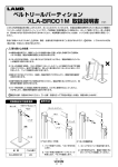
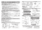
9
製品内容
図1
上側目地C
(2 .4以上)
(95)
D = 32 + T − (
23.5
扉
(101.5)
(45)
取手
取手位置(推奨)
背板
B
※この取付位置は、3[mm]のパッキンを使用したときの
寸法です。パッキンを使用しない場合は、製品を背板側に
3[mm]ずらしてください。
パッキン厚 推奨 3
100
(10)
W0 − W1
)
2
W 0 = キャビネット外幅
T = キャビネット側板の板厚
t = キャビネット天板の板厚
W1 = 扉外幅
C = 上側目地(2.4以上)
425 (扉移動量)
32
352.5 (金具収まり寸法)
38
31
34
キャビネット内のり高さ h 354以上
注意 以下の注意事項を守らないと、思わぬけがをしたり、周辺の家財に損害を与えたりする恐れがあります。
施工上の注意
● 本製品は、必ず左右セットでご使用ください。
● 本製品で使用する扉は、幅方向の中央に必ず取手を取り付け、取手を持って開閉してください。
● キャビネットおよび扉は水平、垂直に製作してください。
● 本製品の取付位置は、必ず指定寸法、水平、垂直度に注意して正しく行ってください。指定寸法以外での取り付けや傾きは、本製品の性能が
発揮できないばかりではなく、破損等による思わぬけがをする恐れがあります。
● ばね力調節は、左右のねじ調節量が同じになるよう調整してください。差異があると、左右どちらかの製品に荷重負担が集中し、製品の寿命や
機能に影響する可能性があります。
● 扉は反り、ねじれが発生しにくい構造にしてください。
● 扉を取り付ける前の状態で、アームを手で押し下げないでください。製品が破損したり、アームがはねあがって大けがをする恐れがあります。
使用上の注意
● 扉を開ききった状態からさらに開いたり、必要以上の力で扉を閉めたりなど無理な扉の開閉は故障の原因となるので、絶対におやめください。
● ご使用になる際は、アームに指をはさまないようにご注意ください。思わぬけがをする恐れがあります。
● 本製品の使用温度範囲は5℃∼35℃です。温度変化により扉の閉止速度が変化しますが、故障ではありません。
● 使用温度範囲以外でのご使用はおやめください。発熱するマイクロオーブンレンジ等のキャビネットには絶対に使用しないでください。
● 本製品の分解、改造は決して行わないでください。
● 取付ねじにゆるみが無いことを定期的に確認してください。ゆるみがあった場合は、増し締めしてください。
79.5
B = 244 + t − C
このたびは、弊社製品をお買い上げいただきまして、まことにありがとうございます。取り付け前に本説明書をよくお読みのうえ、正しく
取り付けてください。誤った取り付けは、思わぬけがをする恐れがあるのでおやめください。施工後は、ご使用になられる方へ本説明書を
お渡しし、いつでも読めるよう保管してください。
● 本製品は扉用スイングリフトアップ金具です。これ以外の使用方法や、使用範囲外の扉に使用したことによる故障、けがなどにつきましては、
その責任を一切負いかねますのでご了承ください。
● 本説明書の製品内容は、部品としての品質範囲です。本製品を使用した最終製品の機能・性能・安全性を保証するものではありません。
必ず最終製品でのご確認をいただくよう、お願いいたします。
● 製品については万全を期しておりますが、万一不良品があった場合、ご購入先へお問い合わせください。
保証期間は弊社納品書発行日から1年間とさせていただき、良品との交換をもって責任の範囲とさせていただきます。但し、ダンパー部分の
不具合につきましては、ダンパー本体のみ良品との交換をもって責任の範囲とさせていただきます。
● 製品改良などにより、予告なく寸法、材料などの仕様変更を行う場合があります。念のため現品にてご確認ください。
● 汚れがひどい場合は、中性洗剤を水で薄めてふきとってください。アルコールやシンナーなど揮発性のものは表面の仕上げを傷めるので、
使用しないでください。
86.5
PAT
167.5
6.5
19
108.5
スイングリフトアップ金具 SLUN-N型 取扱説明書
取付寸法図
D寸法(扉端面基準)
図3−1.本体取付寸法図
図3−2.座金プレート取付寸法図
取付手順
④バインド
タッピンねじ
(3.5×15)
1. SLUN-N本体の取り付け
(1)①②SLUN-N本体をキャビネット内側の上部及び間口前面に合わせ、付属の④取付ねじ(3.5×15)
で固定します(図3−1、図4)。
図.4
2. 扉の取り付け
(1)座金プレートを扉裏面の規定位置に、付属の④取付ねじ(3.5×15)で確実に固定します(図3−2)。
(2)扉に取手を取り付けます。
※取手は、③座金プレートの下端を限度に、なるべく上に取り付けてください(図3ー1)。
a
a
a
a
(3)③座金プレートと、SLUN-N本体のアーム先端の座金を合わせてはめ込み、aねじを締め付けます(図5)。
① SLUN-N本体(右)
⑤ ダンパー本体
2ケ
② SLUN-N本体(左)
③ 座金プレート 2ヶ
⑥ ホルダーベース ⑦ ディスタンス
2ケ
プレート 2ケ
図.5
扉を取り付ける前の状態で、アームを手で押し下げないでください。
製品が破損したり、アームがはねあがって大けがをする恐れがあります。
3. 連動バーの取り付け
④ バインドタッピンねじ(3.5×15)
16本
別売
※必ず使用する
別売り品
4. ダンパーの取り付け
(1)⑦ディスタンスプレート及び、⑥ホルダーベースを、付属の⑧取付ねじ(3.5×20)で
取り付けます(図7)。
⑩ 連動バー取付ねじ
(4.5×12) 4本
連動バーの長さL
⑨ 連動バー
機種の選定
表1. 適用扉質量
W0
図2
扉質量[kg]
寸法 [mm]
SLUN-3N 2.8∼3.8
キャビネット幅 (W0) 600 、900
機種
t
SLUN-4N 3.8∼4.8
SLUN-5N 4.8∼5.8
H1
h
W1
W0 = キャビネット外幅
T = キャビネット側板の板厚
h = キャビネット内のり高さ
t = キャビネット天板の板厚
W1 = 扉外幅
H1 = 扉高さ
T
表3. 連動バーの長さL
表2. 使用範囲
扉高さ (H1)
390 ∼ 450
⑨連動バー
(1)アームA部の所に、⑨連動バーを ⑩取付ねじ(4.5×12)で確実に固定します(図6)。
扉中央部がガラスの場合などで連動バーを目立たせたくない場合は、アームB部の所で同様に固定できます。
※連動バーの長さが異なりますのでご注意ください。
※連動バーが緩んだ場合は、再度⑩取付ねじ(4.5×12)を増し締めしてください。 ⑧ 皿タッピンねじ
(3.5×20) 6本
535
835
アームB部 (ガラス扉)
551
851
・本製品は 表1.の適用扉質量にしたがって機種を選択してください(取手質量を含む)。
・表3の寸法は、キャビネットの側板 T が15 [mm]の際の、弊社標準在庫品です。側板の板厚(T)が
15 [mm]以上の場合は、下記の計算式に従って連動バーを切断加工してください。
アームA部に連動バーを取り付けることを基本としますが、より剛性を必要とする場合は、
アームB部にも取り付けてください(図6)。
アームA部の場合: L = W0 − ( T × 2 ) − 35
アームB部の場合: L = W0 − ( T × 2 ) − 19
※アームA部とB部で、連動バーの長さが異なるのでご注意ください。
※上記キャビネット以外への取り付けの場合は、弊社営業担当者までお問い合わせください。 ⑧皿タッピンねじ(3.5×20)
⑥ホルダーベース
⑦ディスタンスプレート
図.7
アームB部
図.6
アーム
⑤ダンパー本体
ストッパーブロック
図.8
調節方法
a
1. 高さ方向
(1) aねじを緩めます。
(2) 下からbねじを左に回すと
扉が上がります。
(3) aねじを確実に締め付けます。
b
2. 横方向
(1) cねじを緩めます。
(2) 扉を左右に調節します。
(3) cねじを確実に締め付けます。
3. 前後の傾き
(1) aねじを緩めます。
(2) dねじを左に回すと扉先端が
キャビネット側に傾きます。
(3) aねじを確実に締め付けます。
2012.12 PRINTED IN JAPAN 0541-4 アームA部
(2)ストッパーブロックが長円穴の一番上にある事を確認し、SLUN-N本体のアームを
図8のように下げた状態で、ダンパー本体を前からスライドさせて取り付けます(図8)。
キャビネット幅 キャビネット幅
600用 [mm] 900用 [mm]
アームA部 (木扉)
⑩取付けねじ
(4.5×12)
c
a
4. 扉ストローク量
(1) eねじを緩めます(図10)。
eねじ
(2) 扉が左右共に、任意の同じ高さで
止まるようにストッパーを調節します。
(3) eねじを確実に締め付けます。
5. ばね力調節
(1) 本体後部のばね力調節ねじで、扉を保持する力を調節
してください。
調節は、六角棒スパナ(呼び5) で行ってください(図11)。
本体後部から見て、右に回すと扉を支える力が強くなり、
左に回すと弱くなります。
※六角棒スパナ(呼び5)は、お客様でご用意ください。
d
c
図.9
図.10
ばね力
調節ねじ
図.11
必要以上にばね力調節ねじを回すと、製品が破損する恐れがあるので
おやめください。
Dimensions
Clearance
(minimum2 . 4)
(95)
79.5
9
(101.5)
Handle
(45)
Handle position
Door
Back panel
B = 244 + t - C + ( h - 354 )
E = 354
W 0 = Cabinet width
T = Cabinet side panel thickness
h = Cabinet inside height
t = Cabinet top board thickness
W1 = Door width
C = Clearance (minimum 2 . 4)
Rubber gasket thickness A
(3 is recommended)
Fig.1
Installation
Arm B
D ( D distance to door edge )
④Binding
tapping screw
(3.5×15)
1. Body installation:
②SLUN-N(L) lefthand side body
1pcs
(1) Draw a horizontal line at 354mm from the inside bottom of the cabinet.
(2) Line up the steel plate of the SLUN-N bodies ① and ② to the front of the cabinet and the line drawn in (1).
(3) Use screws ④ to secure both bodies to the cabinet.
Arm B
Fig.4
354
③Mounting plate
2pcs
W0 - W1
)
2
B
D = 32 + T - (
100
(10)
Arm A
①SLUN-N(R) righthand side body
1pcs
23.5
Fig.3 Dimensions
425 (Door travel distance)
86.5
108.5
32
Parts list
Arm A
6.5
19
15
E 354 (Installation height)
Do not force the door open past its fully opened position.
Do not use in excessively hot environment such as to hide an oven.
Do not insert your hand or finger between the arms as this may lead to sever injury.
Never attempt to open or disassemble the mechanism as this may lead to injury.
Do not pull the arm down as it will spring back up violently and may cause serious injuries.
390∼450 (Cabinet height)
!
!
!
!
!
minimum 354 (Cabinet inside height)
For proper installation and operation, we recommend that you read and follow these instructions carefully.
● Sugatsune cannot accept any claim for damages or injuries caused by improper use of this swing lift-up stay. Please
refer to the “Model Selection“section below for the proper range of use.
● Sugatsune’s liability is limited to the repair or replacement of a defective product. It shall in no way extend to the
assembly as a whole.
● The utmost care was taken during the production of the SLUN-N. Should you however notice any defect, please
notify your local dealer or Sugatsune ([email protected]).
● The warranty period extends to one year from the shipping date.
● For improvement reasons, the content of this set may be changed without prior notice. We recommend that you check
carefully the set content against the part list shown below and report any discrepancy to your local dealer before
installation.
● Operating temperature is 5∼35℃. Function may vary depending on the temperature.
167.5
*The drawing shows the application
for the cabinet with 3mm thick seal
gasket on front edge.
38
PAT
18.5
SWING LIFT UP MECHANISM
31
SLUN-N
2. Door installation:
a
④ Binding tapping screw(3.5×15)
16pcs
a
⑥Holder
2pcs
⑦Distance plate
2pcs
⑧Countersunk tapping screw(3.5×20)
6pcs
Length of guide bar : L
⑨SLUB
*SLUB Bars are available in 4 standard sizes : 535、835、551 and 851mm.
W0 = Cabinet width
T = Cabinet side panel thickness
h = Cabinet inside height
t = Cabinet top board thickness
Fig.2
W1 = Door width
H 1 = Door height
W0
SLUN-3N
2.8∼3.8 kg
SLUN-4N
SLUN-5N
3.8∼4.8 kg
4.8∼5.8 kg
h
T
⑩Truss tapping
screw(4.5×12)
3. Bar installation:
⑨SLUB
(1) Cut the bar to the necessary length as per instructions in the “Model Selection” section.
(2) Install the bar to either arm A or arm B depending on the dimensions selected above. Arm A installation is
recommended for wooden doors as bar is not visible in the open position. Arm B installation is recommended
for glass door as bar is less visible in the closed position.
Door size:
Stopper
Arm A installation: L= W0 - ( T x 2 ) - 35
Arm B installation: L= W0 - ( T x 2 ) - 19
Fig.6
(1) Line the distance plate ⑦ and the holder ⑥ with the holes for the damper (Fig.7) and
secure them with screws ⑧.
(2) Slide the damper ⑤ into the holder from the front side.
⑦Distance plate
Fig.7
Fig.8
Fig.9
Adjustment
Fig.10
a
① Loosen both a screws
② Adjust height by turn b screw
③ Refasten both a screws securely
① Loosen both e screws on both sides
② Adjust height of the opened door
similarly on both sides.
③ Refasten both e screws securely
b
c
① Loosen both c screws
② Adjust door position
③ Refasten both c screws securely
e
a
Spring strength adjustment:
① Loosen both a screws
② Turn screw d left to bring the top of
the door closer to the cabinet
③ Refasten both a screws securely
2012.12 PRINTED IN JAPAN 0541-3 (B)
4. Damper installation:
⑥Holder
SLUB bar needs to be cut depending on the cabinet width W0 and
side panel thickness T.
Bar length L will depend on whether it is installed on Arm A or Arm B
(see Fig.1).
(A)
⑤Damper
Width (W1) 600、900mm
Height (H1) 390∼450mm
Select the SLUN type according to the weight of the door (including
the handle).
t
W1
Applicable door weight:
Do not pull the arm down as it will spring back up violently and may cause serious injuries.
Fig.5
⑧Countersunk tapping
screw(3.5×20)
Model slection
H1
⑩Truss tapping screw
(4.5×12) 4pcs
!
a
Sold separately
⑤Damper
2pcs
(1) Install the mounting plates ③ to the back side of the door as per dimensions shown in Fig.3.
(2) Line up both a screws of each mounting plates with the slots of the arms and slide the door down.
* Make sure that the screws are properly inserted in the slots before releasing the door.
(3) Fasten both a screws securely.
a
Fig.11
Turn the screw at the back of stay body to
adjust the spring strength.
d
!
!
c
Spring strength should be adjusted similarly on both units.
Do not set the spring strength too high as the door may
open violently and damage the system.
-
+