Download 取扱説明書
Transcript
HIR 0003-03
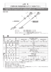
取扱説明書
エアーフィルタ 、 ミストフィルタ 、 マイクロミストフィルタ 、
レギュレータ 、 フィルタレギュレータ
5-2. エレメント交換手順 ( 図参照 )
(2). フィルタエレメント FE300D (0.3µm 用 )、FE300M (0.01µm 用 ) が装着されている場合。
1) 5µm エレメント(FTA300- □ - □ D)
(フィルタエレメント底部に十字穴付きナベ小ネジが付いていません。)
本体▼印
① .O リングの取外し
①.1回目の交換時は本体からフィルタエレメントFE300DまたはFE300Mを取り外しフィルタエレメントセッ
バッフル中央部に装着されている O リングをピンセット等で取り外
1. 取付け、配管
してください。
●本製品は、使用される空気圧機器のできるだけ近くに取付けてください。
●エアーの流れが IN から入るように配管してください。( 印の側が IN になります。)
●取付ける際、切削油等油分を必ず除去し、十分フラッシングを行ってください。
●フィルタ、ミストフィルタ、マイクロミストフィルタ、フィルタレギュレータの取付けは、ドレンコックを下向き
にして垂直に取付けてください。
2. 雰囲気、環境
●直射日光、雨、水のかかる場所での使用は避けてください。
●フィルタ、ミストフィルタ、マイクロミストフィルタ、フィルタレギュレータのボウル材質はポリカーボネートで
すので、有機溶剤等の雰囲気中では絶対に使用しないでください。
3. 保守、点検
●プラスチックボウルの洗浄には、中性洗剤を使用してください。アルコール、シンナー等による洗浄は避けてください。
● 5µm エレメントは、中性洗剤により洗浄し再使用できますが、0.3µm、0.01µm エレメントは再使用できません。
ト FE300DK または FE300MK に交換してください。
② .2 回目以降は (1). フィルタエレメントセット FE300DK、FE300MK の交換手順に従って交換してください。
ロック溝
② . バッフルの取外し
エレメントのみ(FE300DN、FE300MN)の交換となります。
バッフルを取り外してください。( 構造上、爪により固定されている
ためきつい )
フィルタエレメント (5µm)
バッフル
③ . エレメントの取外し
6. レギュレータの操作
O リング (P4)
④ . エレメントの洗浄、又は交換
⑤ . バッフルの取付け
バッフルを”カチッ”と音がする位置まで押し込んでください。
⑥ .O リングの取付け
圧力設定手順
① . 圧力を設定する場合は、ハンドルを引き上げロックを解除してから廻してください。
② . 右 ( 時計廻り ) に廻すと圧力が上がり、左 ( 反時計廻り ) に廻すと圧力が下がります。
( 注 1). 圧力設定は、上昇方向 ( 右廻り ) で設定してください。
( 注 2). 過度のハンドル回転操作は、動作不良の原因となります。
③ . 圧力設定が終了したらハンドルを押し下げロックされている事を確認してください。
O リング (S38)
ロックレバー▲印
バッフル中央部に O リングを装着してください。
ロックレバー
( 注 )O リングは、新品と交換してください。
③
①
②
●エレメントの寿命は、圧力降下が 0.07MPa に達した時寿命となります。寿命となりましたら分解、洗浄又は新品と
交換してください。
4. ドレンの排出
2) 0.3µm、0.01µm エレメント(FTD300- □ - □ D、FTM300- □ - □ D)
4 − 1. プッシュ式ドレンコック
●プッシュ式ドレンコックは、下記によりドレン排出がされます。
① . プッシュボタンを手動操作した時。
② . 配管内圧力がゼロになった時。
●ドレン配管を行う場合、内径 6mm のチューブを使用し、長さ 5m 以内で立ち上が
り配管は避けてください。
●プッシュ式ドレンコックは、圧力が 0.05MPa に上昇するまではドレン排出口より
エアーが排出されますが異常ではありません。
蛞 ドレン排出
(フィルタエレメント底部に十字穴付きナベ小ネジがついています。)
① . フィルタエレメントセットの十字穴付ナベ小ネジを
使用し、フィルタエレメントセットを取り外す。(ネ
ジガイドが本体に残った場合はそのままで結構です。
③に進んでください。)
② . 十字穴付ナベ小ネジをネジガイドから外す。
③ . エレメントの取外し
スクリュウ式
ドレンコック
④ . フィルタエレメントセット取り外し時にネジガイドも
外れた場合は、ここで本体にネジガイドをねじ込み
取り付ける。
手 動 操 作 の 場 合、
左(反時計廻り)
に廻すとドレンが
排出されます。
⑥ . 十字穴付ナベ小ネジにガスケット、キャップガイド、
フィルタエレメント (0.3µm、0.01µm)
リンク
⑦ . フィルタエレメントを取り付けたネジガイドに⑥の部
キャップガイド
品を十字穴付ナベ小ネジを使用して締め付ける。こ
ガスケット (GAS-M4)
の時の締め付けトルクは 0.9 ∼ 1.1N・m で締め付けて
十字穴付ナベ小ネジ
ください。
本体▼印
PUSH
価格 (¥)
370
3,300
2,900
3,500
3,100
30
1,900
20
100
50
該当機種
エアーフィルタ (FTA 300- □ - □ D)
ミストフィルタ (FTD 300- □ - □ D)
マイクロミストフィルタ (FTM 300- □ - □ D)
エアーフィルタ (FTA 300- □ - □ D)
レギュレータ(RVF 300-□)、フィルタレギュレータ(FRF 300-□-□D)
ミストフィルタ(FTD 300-□-□D)、マイクロミストフィルタ(FTM 300-□-□D)
エアーフィルタ(FTA 300-□-□D)、ミストフィルタ(FTD 300-□-□D)、マイクロミストフィルタ(FTM 300-□-□D)
ミストフィルタ(FTD 300-□-□D)、マイクロミストフィルタ(FTM 300-□-□D)
O リング (S38)
ロックレバー▲印
ロックレバー▲印
ロックレバー
本体▼印
注文形式
FE300A
FE300DK
FE300DN
FE300MK
FE300MN
P4
GK46-B20
GAS-M4
S38
S20
ネジガイド
リンクの順で部品を挿入する。この時キャップガイ
ドは突起の無い方をガスケット側にする。
② . ボウル取付け時
本体▼印
O リング (S20)
⑤ . ネジガイドに新しいフィルタエレメントをはめ込む。
5 − 1. ボウルの着脱手順 ( 図参照 )
① . ボウルの取外し
ロックレバーを押しながらボウルガードを回転させ、ロックレバー▲印を本体▼印に合わせると取外せます。
( 注 ). ボウル内の圧力が無い事を確認してから取外してください。
② . ボウルの取付け
ロックレバー▲印を本体▼印に合わせ、ボウルガードを奥まで挿入し本体に押しつけながら回転させ本体中央
のロック溝にロックレバーを合わせると固定されます。
( 注 ). ボウルが確実に固定された事を確認し圧力を印加してください。
ロックレバー▲印
交換部品名
5µm フィルタエレメント
0.3µm フィルタエレメントセット
0.3µm フィルタエレメント
0.01µm フィルタエレメントセット
0.01µm フィルタエレメント
O リング ( バッフル用 )
角形圧力計(ダイレクトマウント形)
ガスケット
O リング ( ボウル用 )
O リング ( ネジガイド用 )
いる場合。
5. ボウルの脱着及びフィルタエレメントの交換
① . ボウル取外し時
7. 交換部品の注文形式
(1). フィルタエレメントセット FE300DK (0.3µm 用 )、FE300MK (0.01µm 用 ) が装着されて
フィルタエレメントセット
4 − 2. オートドレン式ドレンコック
●オートドレン式ドレンコックは、下記によりドレン排出がされます。
① . スクリュウ式ドレンコックを手動操作した時。
② . 一定のドレンが溜まった時。
③ . 配管内圧力がゼロになった時。
●ドレン配管を行う場合、外径 8mm のチューブを使用し、長さ 5m 以内で
立ち上がり配管は避けてください。
●オートドレン式ドレンコックは、圧力が 0.15MPa に上昇するまではドレ
ン排出口よりエアーが排出されますが異常ではありません。
エレメントの種類により交換方法が異なります。
本体▼印
※ . その他詳細につきましてはカタログ、又は最寄りの営業所にお問い合わせください。
本体▼印
PUSH
販売元/
本社・営業部/長野県上伊那郡南箕輪村 3884-1 〒 399-4586 TEL : 0265(76)2511 豎 FAX : 0265(76)2851
製造元/
HIR 0003-03
Air Filter, Mist Filter, Micromist Filter, Regulator,
Handling
Instruction
Filter Regulator
1. Installation and Piping
● Install the unit as close as possible to pneumatic equipment in use.
● Make sure the piping so that air comes in from "IN" port (the port marked is "IN" port).
● Before installing, be sure to remove cutting oil and other oils and carry out flushing sufficiently.
● Install the filter and filter regulator vertically with the drain cock facing down.
2. Ambient Conditions
● Do not use the filter and filter regulator in a place exposed to direct sunshine, rain or water.
● Since the bowl material of the Filter, Mist Filter, Micromist Filter and Filter Regulator is polycarbonate, do not use then in the atmosphere
of organic solvent or other chemicals designated by manufacturer.
5-2. Procedure for replacement of element (see illustration)
1). 5µm element (FTA300- □ - □ D)
① . Removal of the O-ring
Remove the O-ring fitted in the center of the baffle, using tweezers.
② . Removal of the baffle
Remove the baffle. (Held by fingers, it dose not come off easily)
③ . Removal of the element
④ . Cleaning or replacement of the element
⑤ . Installation of the baffle
Push in the baffle until you hear a click sound.
⑥ . Installation of the O-ring
Fit the O-ring in the center of the baffle.
NOTE: Replace the O-ring with a new one.
(2).In case of filter element FE300D (For 0.3µm) and FE300M (0.01µm) are equipped.
FE300DK or FE300MK.
② .From the second time of replacement, please follow the replacement procedure of (1) of FE300DK and FE300MK. Replace
Lock groove
baffle
蛞 Discharge of
drainage
will lower.
②
Note1) Set the pressure in the rising (clockwise) direstion.
Note2) The excessive handle rotation may cause malfunction.
Lock lever
③ . On completion of the pressure setting, push in the handle and make certain that it is locked.
7. Model Designation of Replacement Parts
① . Using the cross-recessed round head screw, remove filter
please leave it as it is and proceed to ③ .)
② .Remove the cross-recessed round head screw from the screw
④ .In case the screw guide comes off at the same time the filter
Screw-type
drain knob
element set is removed, screw it into the main body.
⑤ .Install a new filter element into the screw guide.
Replacement parts
Model
Price (¥)
5µm filter element
FE300A
370
0.3µm filter element set
FE300DK
3,300
0.3µm filter element
FE300DN
2,900
0.01µm filter element set
FE300MK
3,500
0.01µm filter element
FE300MN
3,100
O-ring (for baffle)
guide.
③ .Remove the element.
Square pressure gauge (direct mount type)
Gasket
▼ mark on the body
Applicable unit
Air Filter (FTA 300- □ - □ D)
Mist Filter (FTD 300- □ - □ D)
Micromist Filter (FTM 300- □ - □ D)
Air Filter (FTA 300- □ - □ D)
P4
30
GK46-B20
1,900
Regulator (RVF 300- □ ), Filter regulator (FRF 300- □ - □ D)
GAS-M4
20
Mist Filter (FTD 300- □ - □ D), Micromist Filter (FTM 300- □ - □ D)
O-ring (S20)
O-ring (for bowl)
S38
100
Air Filter (FTA 300-□-□D), Mist Filter (FTD 300-□-□D), Micromist Filter (FTM 300-□-□D)
Screw guide
O-ring (for screw guide)
S20
50
Mist Filter (FTD 300- □ - □ D), Micromist Filter (FTM 300- □ - □ D)
⑥ .Insert the parts into the cross-recessed round head screw in the
order of gasket, cap guide and link. Do not place the gasket next
to the protruding side of the cap guide.
⑦ .Tighten the ⑥ parts by the cross-recessed round head screw
to the screw guide with filter element. Please apply tightening
5-1. Procedure for removal and installation of bowl (see illustration)
① .Removal of bowl
Turn the bowl guard while pushing the lock lever, and the bowl will come off when the ▲ mark on the lock lever is aligned with the
▼ mark on the body.
NOTE: Before removing the bowl, be sure to mark certain that there is no pressure working in it.
② .Installation of bowl
Align the ▲ mark on the lock lever with the ▼ mark on the body, insert the bowl guard fully, turn it while pressing it to the body, and
lock the bowl by fitting the lock groove in the center of the body.
NOTE: Apply pressure only after marking certain that the bowl is securely locked.
PUSH
③
①
② . Turn the handle clockwise, and the pressure will rise. Turn it counterclockwise, and the pressure
element set. (If screw guide remains inside of the main body,
5. Removal and Installation of Bowl and Replacement of Filter Element
▲ mark on
the body
① . When setting a pressure, pull out on the handle, release the lock, and turn the handle.
(1).In case of the filter element set FE300DK (for 0.3µm) and FE300MK (for 0.01µm) are equipped.
(A cross-recessed round head screw is attached to the bottom of filter element.)
turn drain knob
counter clock wose.
▲ mark on the body
Pressure setting procedure
O-ring (S38)
The replacement procedure differs from element types.
4-2. Auto drain type drain cock
● The auto drain type drain cock discharges the drainage when
① . The screw-type drain knob is manually operated,
② . Drainage has accumulated to a specified lever, or
③ . The pressure inside the piping has dropped to zero.
● In drain piping, use a tube of 8mm in outside diameter and do not install any acclivity
within 5-meter length.
● The auto drain type drain cock discharges air from the drain outlet until the pressure
rises to 0.15MPa. Note that this is a normal procedure.
For manual drain,
② . Installation of bowl
6. Operation of Regulator
O-ring (P4)
2) 0.3µm and 0.01µm element (FTD300- □ - □ D、FTM300- □ - □ D)
4-1. Push type drain cock
● The push type drain cock discharges the drainage when
① . The push button is manually operated or
② . The pressure inside the piping has dropped to zero.
● In drain piping, use a tube of 6mm in inside diameter and do not install any acclivity within
5-meter length.
● The push type drain cock discharges air from the drain outlet until the pressure rises to 0.05MPa.
Note that this is a normal procedure.
▼ mark on the
lock lever
the element only. (FE300DN, FE300MN)
Filter element (5µm)
● Wash the plastic bowl, using a neutral detergent. Never wash it with alcohol or thinner.
● The 5µm element can be used again after washing with a neutral detergent. However, the 0.3µm and 0.01µm elements can not be used
again after washing.
● The element's life ends when the pressure drop reaches 0.07MPa. At this point, disassemble the unit and wash the element, or replace
the element with a new one.
① . Removal of bowl
① .On the first time of replacement, remove the filter FE300D or FE300M from the main body and install filter element set
▲ mark on the lock lever
3. Maintenance and Checks
4. Draining
(A cross-recessed round screw is not attached to the bottom of filter element.)
▼ mark on the body
▼ mark on the
lock lever
▲ mark on the body
Link
Filter
element
set
Cap guide
Gasket (GAS-M4)
Cross-recessed round head screw
O-ring (S38)
▲ mark on the lock lever
Lock lever
▲ mark on
the body
PUSH
torque of 0.9 ~ 1.1N ・ m.
Filter element (0.3µm、0.01µm)
※ . Please contact your nearest PISCO office or refer to catalogue for other detail.
INTERNATIONAL MARKETING DEPT.
3884-1 MINAMIMINOWA, KAMIINA, NAGANO-PREF, 399-4588 JAPAN
TEL: +81-265-76-7751 FAX: +81-265-76-7789 URL: pisco.co.jp/english/pisco.htm E-mail: [email protected]


