1
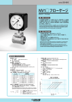
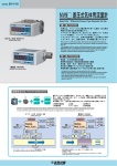
Cat.No. E01-13-G
NV6□・8□ 差圧式デジタル流量計
Model NV6□・8□ Differential Pressure Digital Flowmeter
概 要/OUTLINE
高感度差圧センサと流量検出部をコンパクトに一体化。
設置工事の大幅な省力化で省エネルギー管理計測に貢献します。
High-sensitivity differential pressure sensor and flow rate detector integrated in a
compact size.
Contributing to energy-saving control measurement through remarkably laborsaving
installation works.
NV60
特 長/FEATURES
NV6 シリーズ
本製品は、微小な差圧を高感度で検出するシリコンキャパシタンスセ
ンサを搭載した差圧式デジタル流量計です。
ピトー管式とオリフィス式
の流量検出部を選択可能で、流量測定用途へ使用することができます。
また、多機能な表示演算部を搭載し、用途に応じて表示、出力形態を
選択できます。
NV8 シリーズ
本製品は、NV6に比べて耐環境性を向上させた小形でコンパクトな
差圧式デジタル流量計です。2線式でありながら、見やすいバックライ
ト付LCD表示を搭載しています。
NV6 Series
NV81
This product is a differential pressure digital flowmeter mounting a high-sensitivity
silicon capacitance sensor for detecting micro differential pressure. The flow rate
detector can be selected from the Pitot or Orifice type, allowing it to be used for flow
rate measurement applications. The product mounts the multifunction display and
operation unit enabling selection of the display and output forms according to each
individual application.
NV8 Series
NV8 is a compact flowmeter in small-sized to improve difference pressure accuracy
and environmental resistance. It has the LCD with the backlight which is easy to see
while it is 2 wire type output.
差圧検出部の特長/FEATURES OF THE DIFFERENTIAL PRESSURE DETECTOR
高感度「SCセンサ(シリコンキャパシタンスセンサ)」をSUS316Lのダイアフラムにより液封すること
で、過大圧に強い構造としました。また、均圧弁と三岐弁を一体化した専用コックによりコンパクト化
を実現、流量検出部は「ピトー管式」「オリフィス式」が選択可能です。
It is the structure which is resistant to the excessive pressure sealed in liquid by means of high sensitivity silicon capacitance sensor with diaphragm
SUS316L. It is realized that it becomes compact by the specialized cock which unified the three-way valve with the equalizing valve. The flow rate
detector can be selected from the Pitot tube type or Orifice type.
シリコーンオイル
Silicone oil
ピトー管式
(NV60,80)
Pitot tube type (NV60/80)
ダイアフラム
SUS316L
SUS316
Diaphragm
SUS316L
専用コック
(均圧弁機構付)
Specialized cock (with equalizing valve mechanism)
オリフィス式
(NV61,62,63,81,82,83)
Orifice type (NV61/62/63/81/82/83)
NV6□・8□ 差圧式デジタル流量計
NV6 Series
警報出力モニタ
(2出力)
測定値表示部
Alarm output monitor (2 outputs)
Measurement value display
リニアライズ補正表示
(オプション)
電池電圧低下モニタ
Battery voltage drop monitor
Linearize correction display
(option)
UNIT
バーグラフメータ表示
100
m3/h
Bar graph meter display
圧力単位表示
50
Pressure unit display
動作モニタ
0
Operation monitor
SET … Turns on in the setup mode.
ADJ. … Turns on when zero adjustment is enabled.
Aoff … Turns on when auto power OFF is enabled.
積算表示(オプション)
℃
SET
ADJ.
Aoff
SET … 設定モード中に点灯
ADJ.…ゼロ調整有効時に点灯
Aoff … オートパワーOFF有効時に点灯
Integral value display (option)
Enter キー
Enter key
MODE
Enterキーは主に設定モードへの移行及び
設定項目の切替えに使用します。
MODE キー
The Enter key is used mainly to shift to
the setup mode and select settings.
MODE key
MODEキーは主に電源OFFへの移行及び
他のキーと組み合せて使用します。
Down, Up キー
The MODE key is used mainly to switch the power OFF,
and also used in combination with other keys.
Down, Up key
Down,Upキーは主に数値の設定
及び選択に使用します。
流量、流速表示(開平演算機能)
モニタ
The Down and Up keys are used mainly
to set up and select numerical values.
Flow rate and velocity display (root square operation function) monitor
表示演算部共通の特長/FEATURES OF DISPLAY AND OPERATION UNIT
演算部としてGC50デジタル差圧計を用いています。/The operation unit make use of model GC50 digital differential pressure gauge.
① 大 型 L C D ……………………………… バーグラフメータ付で設定の確認や、保守点検が容易。
Large size LCD
The bar graph meter makes setup check, maintenance, and inspection easy.
(2線式の電流出力仕様は除く)
② バ ッ ク ラ イ ト …………………………… 暗所での表示の読み取りが可能。
Back light
The display can be read even in a dark place (except the 2-wire current output type).
③ フ ィ ル タ 機 能 …………………………… 圧力変動による表示のバラツキを抑えることが可能。
(0、2、4、8、16、32秒のいずれかの移動平均値を選択)
Filter function
Display dispersion caused by pressure variation can be suppressed. (Select the moving average value from 0, 2, 4, 8, 16, and 32 sec.)
④ ゼ ロ 調 整 機 能 ………………………… ワンタッチで表示のゼロ点調整が可能。
Zero point adjustment function
⑤ 差 圧 表 示 機 能
Zero point adjustment of display is possible with a one-touch operation.
…………………… 流量表示、差圧表示を切替にて確認可能。
Differential pressure display function
The flow rate display and differential pressure display can be switched between for confirmation.
⑥ ス ケ ー リ ン グ 機 能 …………………… 表示、
出力共にレンジ範囲内での自由なアプリケーションが可能。
Scaling function
Display and output applications within the range are possible.
⑦ 積 算 表 示 機 能 (機能オプション) ………… 7 1/2桁表示。積算係数の選択が可能。
Integral value display function (option)
7 1/2 display. Selection of the integral coefficient is possible.
出力形態/OUTPUT TYPE
電池式
電池式+温度入力
電流出力(2線式)
Battery-operated
Battery-operated with temperature input
Current output (2 wires)
形 態
Type
Pt100Ω白金測温抵抗体が接続可能。
2線式 4∼20mA DC出力
Allowing connection of a resistance
temperature sensor (Pt 100 ohms).
2-wire 4-20mADC analog output
UNIT
100
電線取出口位置
Wire outlet position
電 源
Power supply
m3/h
m3/h
With alarm output (3 wires)
警報出力を独立で2出力搭載。
3線式4∼20mA DC出力。
Allowing two independent alarm outputs to
be mounted. Analog output (4-20mA)
UNIT
100
警報出力+電流出力(3線式)
UNIT
100
m3/h
UNIT
100
50
50
50
50
0
0
0
0
℃
SET
ADJ.
Aoff
MODE
乾電池式
(LR6×2)
Operates on dry batteries (LR6 x 2).
℃
SET
ADJ.
Aoff
MODE
℃
SET
ADJ.
Aoff
MODE
乾電池式
(LR6×2)
Operates on dry batteries (LR6 x 2)
2
m3/h
℃
SET
ADJ.
Aoff
MODE
24V DC 外部電源
24V DC 外部電源
Operates on an external 24VDC power supply
Operates on an external 24VDC power supply
NV6□・8□ 差圧式デジタル流量計
NV6 製作仕様/SPECIFICATIONS
仕 様 項 目 Item
仕 様 内 容 Description
1. 測定流体/Fluid under measurement
水又はその他の液体、気体(その他の液体、気体はオリフィス式のみ)※1
Water, other liquids or gas (Other liquids and gas supports only Orifice type) ※1
2. 許容最大圧力/Allowable maximum pressure
両耐圧:2MPa
(負圧−90kPa)※2
Maximum static pressure: 2MPa (negative pressure -90kPa) ※2
3. 許容最大差圧
片耐圧:700kPa
(差圧レンジ5kPa以上)
200kPa
(差圧レンジ2kPa以下)
Allowable differential pressure: 700kPa (differential pressure range 5kPa or over)
−10∼90℃
(氷結なきこと)※3
−10 to 90℃ (without freezing) ※3
Allowable maximum differential pressure
4. 測定流体温度/Fluid temperature
200kPa (differential pressure range 2kPa or less)
5. 使用周囲温度・湿度/Operating temperature and humidity
10∼50℃、85%RH 結露・氷結なきこと 電池式は5∼45℃
10 to 50℃, 85%RH (without freezing and condensation) 5 to 45℃ for battery-operated type
6. 保存温度・湿度/Storage temperature and humidity
−20∼60℃、
85%RH 結露・氷結なきこと
−20 to 60℃, 85%RH (without freezing and condensation)
7. 配管口径/Pipe bore diameter
15A∼50A 標準(オリフィス) 20A∼150A 標準(ピトー管)
15A to 50A standard(Orifice type)
8. 適合配管/Applicable pipe
配管用炭素鋼鋼管(JIS G 3452)1MPa仕様
圧力配管用炭素鋼鋼管(JIS G 3454 Sch40)2MPa仕様
Carbon steel pipe for plumbing (JIS G 3452) with 1MPa specification
9. 表示精度/Display accuracy
±3%F.S.
(オリフィス)
±5%F.S.
(ピトー管)
差圧精度 ±
(1.0%F.S.+1digit)
at 23℃
±3%F.S. (Orifice)
10. 測定範囲/Measurement range
フルスケールの10∼100%
10 to 100% of full scale
11. 保護等級/Degree of protection
IP65
(JIS C 0920 防噴流型)
相当
IP65 (JIS C 0920 jet-proof type)
12. プロセス接続/Process connection
①ネジ接続(Rc、NPT) ②はさみ込み接続 ③フランジ接続 ④ピトー管
①Screw connection (Rc, NPT) ②Wafer type ③Flange connection ④Pitot tube
13. 取り付け姿勢/Mounting posture
表示読み取り方向取り付け 縦・横配管可能
Mounted into display readout direction, vertical and horizontal piping possible
14. 必要直管長 D:配管内径
上流条件 90°
エルボ 上流側10D以上 下流側4D以上
上流条件 バルブ(全開) 上流側12D以上 下流側4D以上
Upstream condition, 90°elbow: Upstream side 10D or more,Downstream side 4D or more
15. 測定値表示/Measurement value display
3・1/2桁 LCD
(文字高さ18mm)
表示可能範囲 −1999∼1999
3 1/2 digit LCD (digit size: 18mm)
16. 積算表示(オプション)/Integral value display (Option)
7・1/2桁 LCD
(文字高さ5mm)
表示可能範囲 0∼19999999
7 1/2 digit LCD (digit size: 5mm)
17. バーグラフメータ表示/Bar graph meter display
11セグメント
11 segments
18. バックライト/LCD back light
操作時10秒間点灯 LED 2灯
Required straight tube length, D: Pipe inner diameter
※3
The allowable maximum pressure of the NV61, NV62 and NV63 depends on the connection standard. ※1 蒸気、酸素及びSUS316を腐食させる流体を除きます。
※1 Except steam and oxygen application and a fluid to get the corrosion in SUS316.
※2 NV61、
62、
63の許容最大圧力は、
接続部の規格により異なります。
※2
20A to 150A standard(Pitot tube type)
Carbon steel pipe for pressure plumbing (JIS G 3454 Sch40) with 2MPa specification
±5%F.S. (Pitot tube)
Differential pressure accuracy ±(1.0%F.S.+1digit) at 23℃
Upstream condition, valve (fully open): Upstream side 12D or more,Downstream side 4D or more
Display range −1999 to 1999
Display range 0 to 19999999
LED x 2 (lit up for 10 seconds during operation)
70℃以上の流体については、
下記を注意してください。 ※3
1. 輻射熱が加わらないこと
2. 周辺はラッギングを施さないこと
(センサ部とバルブ部)
3. 周囲温度は50℃以下であること
For fluid of 70℃ or more, refer to the following.
1. Should not apply radiant heat.
2. Should not do lagging around sensor and valve.
3. Ambient temperature is 50℃ or less.
各形態仕様/SPECIFICATIONS FOR EACH OPERATING TYPE
① 電池式/
項
目 Item
内
容 Description
1. 電源/Power supply
単三アルカリ乾電池
(LR6)
×2本
Size AA alkaline battery (LR6) x 2
2. 電池寿命
(連続測定時)
約2年 at 23℃
電池電圧低下
(約2.4V)
をLCD表示します。
About 2 years (at 23℃)
Battery life (under continuous measurement)
Voltage drop (about 2.4V) LCD display
Battery-operated
② 温度入力 /With temperature input
1. 測温抵抗体/Resistance temperature sensor
Pt100Ω
(JIS C 1604-1997)
(3線式)
付属なし
Pt100Ω (JIS C 1604-1997) (3-wire) (not supplied)
2. 温度表示範囲/Temperature display range
−10∼80℃
(範囲外±FFF表示)
−10 to 80℃ (±FFF displayed for out of range)
3. 温度表示精度/Temperature display accuracy
±2℃ at 23℃ 測温抵抗体の誤差は除く
±2℃ at 23℃ Excluding resistance temperature sensor error
外部電源式/
③ 電流出力
(2線式)
/Current output (2 wires)
External power supply
1. 電源/Power supply
24V DC ±10%
2. 電流出力/Analog output
4∼20mA DC
(2線式)
4 to 20mADC (2 wires)
3. 応答性/Response
2秒以下
(フィルタ設定0の場合)
2 seconds or less (with 0 filter setup)
4. 負荷抵抗/Load resistance
600Ω max.
④ 警報出力+電流出力
(3線式)
/With alarm output (3 wires)
1. 消費電流/Current consumption
25mA DC 以下
2. 警報出力/Alarm output
NPNオープンコレクタ2出力
(独立)
NPN open-collector with 2 outputs (independent)
3. 警報出力動作表示/Alarm output operation display
2点 LCD表示部 接断差0設定時動作停止
2 points, LCD display, Operation stopped with 0 deadband
25mADC or less
※演算部詳細については、
GC50デジタル差圧計のカタログを参照ください。/Refer to the catalog of the GC50 Digital Differential Pressure Gauge for details on the operation unit.
3
NV6□・8□ 差圧式デジタル流量計
結線図/WIRING
◎電流出力(2線式)/CURRENT OUTPUT TYPE (2 WIRES)
端子台A
Terminal board A
+
−
+
+
受信計器
−
端子台A
Receiving instrument
適用電線
Terminal board A
−
An applicable electric wire
24VDC
単線 0.14∼1.5mm2
◎警報出力+電流出力(3線式)/ALARM OUTPUT TYPE (3 WIRES)
OUT 2
OUT 1
−
+
負荷/Load
24VDC
ANA
警報出力
(1)
Alarm output (1)
負荷/Load
Alarm output (2)
93
+
−
受信計器
Receiving instrument
(100)
端子台B
A
B
b
Stranded 0.14∼1.0mm2
−
+
◎電池式+温度入力/TEMPERATURE INPUT TYPE
Terminal board B
撚線他 0.14∼1.0mm2
Terminal board B
警報出力
(2)
72
端子台A
Terminal board A
Solid 0.14∼1.5mm2
端子台B
白金測温抵抗体
Pt100Ω
ケーブルグランド
適合ケーブル径 4∼8mm
電流出力
(2線式)
警報出力+電流出力
(3線式)
21
24
ケーブルグランド
適合ケーブル径 4∼8mm
電池式+温度入力
Cable gland
Applicable cable diameter 4 to 8mm
Current output (2 wires)
With alarm output (3 wires)
Cable gland
Applicable cable diameter 4 to 8mm
Battery operated with temperature input
NV8 Series
パネル表示部
Panel display
瞬時流量単位
差圧単位
Unit of momentary flow rate
Unit of differential pressure
任意設定単位
Unit of arbitrary set item
スケーリング表示
& 積算表示
積算体積単位
Scaling display
& integrated volume display
Unit of integrated volume
MODEキー DOWNキー
MODE key
UPキー
DOWN key
UP key
表示演算部共通の特長/FEATURES OF DISPLAY AND OPERATION UNIT
演算部としてGC52差圧トランスミッタを用いています。/The operation unit make use of model GC52 differential pressure transmitter.
① LC D 表 示
暗所や夜間において抜群の視認性
……………………………… 明るく見易いLEDバックライトにより、
LCD display
The bright and clear LED backlight ensures excellent visibility in a dark place or at night.
(kPa)
、瞬時流量
(m3/h、
L/mi
n)
の他に任意の物理量
② ス ケ ー リ ン グ 表 示 ……………………4∼20mADC出力を差圧
Scaling display
In addition to the differential output (kPa) and momentary flow rate (m3/h, L/min) at 4 to 20 mA DC,
arbitrary physical quantities can be displayed.
③ 積 算 体 積 表 示 ………………………… スケーリング表示と交互または単独に、積算体積
(m3、
×10m3)
を6桁表示
Integrated volume display
The integrated volume (m3, ×10m3) is displayed in a six-digit form independently from or alternately with the scaling.
④ ゼ ロ ア ジ ャ ス ト ………………………… キー操作により4∼20mADC出力のゼロ点調整が可能
Zero adjustment
The zero point at 4 to 20 mA DC can be adjusted by key operation.
⑤ ル ー プ チ ェ ッ ク ………………………… 圧力を印加することなく4∼20mADCを任意に出力でき、
メンテナンスが簡単
Loop check
Without applying pressure, 4 to 20 mA DC can be output arbitrarily. This makes maintenance easy.
⑥ フ ィ ル タ …………………………………… 脈動などの圧力変化を移動平均により平滑化
Filter
Pulsations and other pressure changes can be smoothened by moving averages to reduce display fluctuations.
4
NV6□・8□ 差圧式デジタル流量計
NV8 製作仕様/SPECIFICATIONS
仕 様 項 目 Item
仕 様 内 容 Description
1. 測定流体/Fluid under measurement
水又はその他の液体、気体(その他の液体、気体はオリフィス式のみ)※1
Water, other liquids or gas (Other liquids and gas supports only Orifice type) ※1
2. 許容最大圧力/Allowable maximum pressure
両耐圧:2MPa
(負圧−90kPa)※2
Maximum static pressure: 2MPa (negative pressure -90kPa) ※2
3. 許容最大差圧
片耐圧:700kPa
(差圧レンジ5kPa以上)
(差圧レンジ2kPa以下)
200kPa
Allowable differential pressure: 700kPa (differential pressure range 5kPa or over)
−10∼90℃
(氷結なきこと)※3
−10 to 90℃ (without freezing) ※3
Allowable maximum differential pressure
4. 測定流体温度/Fluid temperature
200kPa (differential pressure range 2kPa or less)
5. 使用周囲温度・湿度/Operating temperature and humidity
10∼60℃、
85%RH 結露・氷結なきこと
10 to 60℃, 85%RH (without freezing and condensation)
6. 保存温度・湿度/Storage temperature and humidity
−15∼65℃、
85%RH 結露・氷結なきこと
−15 to 65℃, 85%RH (without freezing and condensation)
7. 配管口径/Pipe bore diameter
15A∼50A 標準(オリフィス) 20A∼150A 標準(ピトー管)
15A to 50A standard(Orifice type)
8. 適合配管/Applicable pipe
配管用炭素鋼鋼管(JIS G 3452)1MPa仕様
圧力配管用炭素鋼鋼管(JIS G 3454 Sch40)2MPa仕様
Carbon steel pipe for plumbing (JIS G 3452) with 1MPa specification
9. 表示精度/Display accuracy
±3%F.S. (Orifice) ±5%F.S. (Pitot tube)
±3%F.S.
(オリフィス)
±5%F.S.
(ピトー管)
差圧精度 ±
(0.5%F.S.+1digit)at 23℃(差圧レンジ5kPa以上)Differential pressure accuracy ±(0.5%F.S.+1digit) at 23℃ (differential pressure range 5kPa or over)
±(1%F.S.+1digit) at 23℃ (differential pressure range 2kPa or less)
±
(1%F.S.+1digit)at 23℃(差圧レンジ2kPa以下)
20A to 150A standard(Pitot tube type)
Carbon steel pipe for pressure plumbing (JIS G 3454 Sch40) with 2MPa specification
10. 測定範囲/Measurement range
フルスケールの10∼100%
10 to 100% of full scale
11. 保護等級/Degree of protection
IP65
(JIS C 0920 防噴流型)
IP65 (JIS C 0920 jet-proof type)
12. プロセス接続/Process connection
①ネジ接続(Rc、NPT) ②はさみ込み接続 ③フランジ接続 ④ピトー管
①Screw connection (Rc, NPT) ②Wafer type ③Flange connection ④Pitot tube
13. 取り付け姿勢/Mounting posture
表示読み取り方向取り付け 縦・横配管可能
Mounted into display readout direction, vertical and horizontal piping possible
14. 必要直管長 D:配管内径
上流条件 90°
エルボ 上流側10D以上 下流側4D以上
上流条件 バルブ(全開) 上流側12D以上 下流側4D以上
Upstream condition, 90°elbow : Upstream side 10D or more Downstream side 4D or more
Six-digit LCD: (Character height: 10 mm, with LED backlight)
15. 測定値表示/Measurement value display
LCD6桁(文字高さ10mm、LEDバックライト付)
スケーリング表示:LCD最大4桁
(差圧表示、瞬時流量表示、その他任意設定表示)
表示周期500ms
Integrated volume display: Six LCD digits max
16. 積算表示/Integral value display
LCD最大6桁
*スケーリングと積算体積の表示方法:
単独表示又は交互表示(切替時間可変)
Required straight tube length, D: Pipe inner diameter
※1 蒸気、
酸素及びSUS316を腐食させる流体を除きます。
※3
※1 Except steam and oxygen application and a fluid to get the corrosion in SUS316.
※2 NV81、
82、
83の許容最大圧力は、接続部の規格により異なります。
※2 The allowable maximum pressure of the NV81, NV82 and NV83 depends on the connection standard. Upstream condition, valve (fully open) : Upstream side 12D or more Downstream side 4D or more
Scaling display: Four LCD digits max.
(Differential pressure, momentary flow rate, and other arbitrary set items)
Display cycle: 500 ms
Scaling and integrated volume display method:
Independent or alternate (Switching time variable)
70℃以上の流体については、下記を注意してください。 ※3
1. 輻射熱が加わらないこと
2. 周辺はラッギングを施さないこと
(センサ部とバルブ部) 3. 周囲温度は50℃以下であること
For fluid of 70℃ or more, refer to the following.
1. Should not apply radiant heat.
2. Should not do lagging around sensor and valve.
3. Ambient temperature is 50℃ or less.
各形態仕様/SPECIFICATIONS FOR EACH OPERATING TYPE
項
目 Item
内
容 Description
1. 電源/Power supply
24V DC±10%
24V DC±10%
2. 電流出力
4∼20mA DC(2線式)
応答性 :100ms(フィルタ設定無しの場合)
負荷抵抗:500Ω max.
4 to 20mA DC (two wires)
Current output
Responsiveness: 100 ms (with no filter setting)
Load resistance: 500Ω max.
※演算部詳細については、
GC52差圧トランスミッタのカタログを参照ください。/Refer to the catalog of the GC52 Differential Pressure Transmitter for details on the operation unit.
結線図/WIRING
結線方法/CONNECTION DIAGRAM
端子 Terminal
裏側接続
側面から見た図
Side view
rear connection
端子台 Terminal block
LCD
電線締め付けネジ
Fastening nuts
+
+
NV8
−
+
−
電源24V DC
切り欠き4ヶ所
Power source
Notch (4 positions)
−
本体
Body
受信計
Receiver
表示部 Display
ケーブル先端 Cable end
5∼8mm
表示部
適合電線 Conforming electric wire
外径
Out diameter
芯線断面積
Wire section area
5∼12mm
Display
フタ Cap
電線 Cable
0.3∼2mm2
※ケーブルはオプションになります。別途ご指定ください。
(2∼10m MAX.)
A cable becomes optional. Please appoint it separately.
5
NV6□・8□ 差圧式デジタル流量計
ピトー管式デジタル流量計
PITOT TUBE TYPE DIGITAL FLOWMETER
NV60
NV80
低圧力損失
水平・垂直配管取付可
小型・軽量
簡単な取り付け
LOW PRESSURE LOSS
HORIZONTAL AND VERTICAL PIPING POSSIBLE
COMPACT AND LIGHT-WEIGHT
EASY INSTALLATION
デジタル流量計は、
ピトー管とデジタル差圧計/トランスミッタを組合せた形態で、
配管内の流速による差圧を検出します。
小型・軽量でビル空調や工場設備等の冷温水配管に簡単に取り付けることができます。
Digital flowmeter detects the differential pressure caused by the flow velocity inside the pipe through the combination of a Pitot tube and digital differential pressure gauge and
transmitter. The compact and light-weight design allows the flowmeter to be installed on cool and hot water pipes for building air conditioning systems, plant facilities, etc.
材質構成/MATERIAL CONFIGURATION
No.
流体検出部・取付コック
Fluid detector and mounting cock
●専用コックがバーチカルタイプの場合
部品名
材質
構成
Part name
Material
Configuration
①
ピトー管
②
エア抜きバルブ
③
袋ナット
④
取り付け金具
⑤
本体
⑥
バルブ軸
⑦
Oリング
⑧
ソケット
●Vertical type
(When the cock piece is mounted vertically)
SUS316
Pitot tube
SUS304
Air release valve
検出部
Detector
SCS13
Hexagon cap nut
SCS14
Mounting fitting
SCS14
Main unit
専用コック
SUS316 + PPS
Valve axis
NBR又はフッ素ゴム選択
O-ring
Specialized cock
※1
Select NBR or fluorine rubber
取付用ポート
SS400
Socket
Mounting port
※1 指示計ダイアフラム部Oリングはフッ素ゴムです。/The indicator diaphragm O-ring is fluorine rubber.
●取付方法/Mounting procedure
②口径40A以上:
φ35穴あけ後、
市販ソケットを溶接。
Make a φ35 hole with a bore diameter of 40A or more, then weld a commercial socket.
②配管口径40A以上
Pipe bore diameter of 40A or more
市販チーズ
Rc3/4
・取り付けのねじ込み深さの目安は、9∼11mmです。ねじ込みすぎないように
ご注意下さい。金具が変形してピトー管が入らなくなるおそれがあります。
The required driving length of mounting screw is approximately 9 to 11mm. Be sure not
to tighten the screw too tight. The fitting may be deformed and the Pitot tube will not enter.
Rc3/4
φ35
Commercial
Tee
Horizontal piping type
●取付上の注意/Notes on mounting
・必要直管長を確保できる取付位置を決定し、取付後に指示計が水平となる
よう穴位置を選定してください。
Determine the mounting position where the required straight tube length can be allocated
and
then select the hole position so that the indicator becomes level after mounting.
・配管口径40A以上ではソケットをφ35の穴に差し込んで配管に溶接してくだ
さい。
この際、
ソケットが配管軸に垂直となるよう正しく溶接してください。
For a pipe bore diameter of 40A or more, insert the socket into the φ35 hole and then weld
it to the pipe correctly so that the socket become perpendicular to the pipe axis.
①口径32A以下:市販チーズ使用
Use a commercial tee with a bore diameter of 32A or less.
①配管口径32A以下
Pipe bore diameter of 32A or less
水平配管タイプ
39
6
NV6□・8□ 差圧式デジタル流量計
NV60/NV80 選定表/NV60/NV80 model selection
※配管内径は、配管用炭素鋼鋼管
(JIS G 3452)
の場合を示します。
( )
寸法は、
チーズ管
(JIS B 2301)
の内容となります。
※下記表を参考にレンジ最大値を指定してください。
※The pipe inner diameter applies to the carbon steel pipe for plumbing (JIS G 3452). The size in ( ) applies to the tee (JIS B 2301).
※Specify maximum measurable range separately referencing the table below.
◎標準フルスケール流量/
測定管径
測定流体
Measuring
fluids
※1 下記以外のレンジにつきましては別途お問い合わせください。※1 For other ranges, contact NAGANO KEIKI.
STANDARD FULL-SCALE FLOW RATE
最小積算値
使用流量範囲 単位:L/min ※1
Measuring pipe diameter
Operating flow rate
レンジ 1/Range 1
呼び
内径 単位:mm
Nominal
diameter
Pipe inner diameter
Unit : mm
20A
(26)
5.0 ∼
50.0
25A
(34)
7.0 ∼
70.0
32A
(43)
40A
41.6
冷温水
50A
Cool & hot
water
(左記流量範囲時)
unit : L/min ※1
レンジ 2/Range 1
単位:L
unit : L
Minimum integral value
(At the table)
レンジ 3/Range 1
差圧センサ 5kPa
差圧センサ 10kPa
差圧センサ 20kPa
レンジ 1
レンジ 2
レンジ 3
Differential pressure sensor
Differential pressure sensor
Differential pressure sensor
Range 1
Range 2
Range 3
10.0 ∼ 100.0
10
10
10
10.0 ∼ 100.0
15.0 ∼ 150.0
10
10
10
12.0 ∼ 120.0
16.0 ∼ 160.0
25
∼ 250
10
10
100
13.0 ∼ 130.0
20
∼ 200
30
∼ 300
10
100
100
52.9
20
∼ 200
30
∼ 300
45
∼ 450
100
100
100
65A
67.9
40
∼ 400
50
∼ 500
70
∼ 700
100
100
100
80A
80.7
50
∼ 500
70
∼ 700
100
∼1000
100
100
100
100A
105.3
90
∼ 900
130
∼1300
180
∼1800
125A
130.8
130
∼1300
150A
155.2
0.20∼
7.0 ∼
2.00★
70.0
100
100
100
0.20∼
2.00★
0.28∼
2.80★
100
1★
1★
0.30∼
3.00★
0.40∼
4.00★
1★
1★
1★
3
★部分の体積単位は m /minです。 The volume unit of (★) mark is cubic meter per minute.
⑧ソケット
Socket
④取り付け金具
配管
Mounting fitting
Pipe
六角穴付止めネジ
(M3)
Hexagon socket setscrew M3
Oリング
(P38)
O-ring (P38)
②エア抜きバルブ
(4個)
Air release valve (x4)
Oリング
(P8)
O-ring (P8)
③袋ナット
Hexagon cap nut
Oリング
(S31.5)
O-ring (S31.5)
ng
溶接
ldi
①ピトー管
We
Pitot tube
エア抜きプラグ
(4個)
Air release plug (x4)
p
止cめ
ram
ネジ
rew
均圧バルブOリング
(P4)
付
Uniform pressure valve with O-ring (P4)
込みg
ネジ win
re
Sc
Sc
六角穴付ボルト、座金M5(4本)
Hexagon socket setscrew,
washer M5 (x4)
mp
止め
cra
ネジ
w
e
r
Sc
コックピース⑤∼⑦
ご注文時指定事項
Specifications when ordering
Cock piece
閉止プラグ
1. 使用流量
(常用、
最高)
Blank plug
Operating flow rate (normal, maximum)
2. 流体名
Fluid name
3. 流体温度
(常用、
最高)
Fluid temperature (normal, maximum)
4. 流体圧力
(常用、
最高)
Fluid pressure (normal, maximum)
5. 流体密度、
粘度
Fluid density and viscosity
指示計
Indicator
六角穴付ボルト M4
(4本)
Hexagon socket setscrew M4 (x4)
Photo NV60
7
NV6□・8□ 差圧式デジタル流量計
オリフィス式デジタル流量計
ORIFICE TYPE DIGITAL FLOWMETER
NV61,62,63
NV81,82,83
小型コンパクト
簡易な設置
水平・垂直配管取付可
多彩な接続形態
SMALL-SIZED AND COMPACT
EASY INSTALLATION
HORIZONTAL AND VERTICAL PIPING POSSIBLE
DIVERSE CONNECTION TYPES
デジタル流量計は、
オリフィスとデジタル差圧計/トランスミッタを組合せた形態で、配管内の流速による差圧を検出します。
各種プロセス接続
(ネジ・はさみ込み・フランジ)
に対応し、
フィールド配管にコンパクトに取り付けることができます。
Digital flowmeter detects the differential pressure caused by the flow velocity inside the pipe through the combination of an Orifice and digital differential pressure gauge and
transmitter. The flowmeter applies diverse process connections (screws, flanges, and wafer) and can be mounted to field pipes compactly.
材質構成/MATERIAL CONFIGURATION
No.
流体検出部・取付コック
Fluid detector and mounting cock
部品名
材質
構成
Part name
Material
Configuration
①
オリフィスプレート
②
ネジ接続
SCS14 + SUS316
Wafer connection
JIS10K用
●Vertical type
(When the cock piece is mounted vertically)
※1
測定管
はさみ込み接続
③
●専用コックがバーチカルタイプの場合
●Gas application type
(When the cock piece is measurement for gas)
SUS316
Orifice plate
Screw connection
●専用コックが気体測定タイプの場合
Measurement tube
SCS14 + SUS316
For JIS 10K
④
フランジ接続
⑤
本体
⑥
バルブ軸
⑦
Oリング
Flange connection
SUS316 又は SUS304選択
SCS14
Main unit
専用コック
SUS316 + PPS
Valve axis
O-ring
SUS316 or SUS304
NBR又はフッ素ゴム選択
Specialized cock
※2
Select NBR or fluorine rubber
※1 測定管は②∼④を選択してください。/Select measurement tube ②, ③, or ④.
※2 指示計ダイアフラム部Oリングはフッ素ゴムです。/The indicator diaphragm O-ring is fluorine rubber.
水平配管タイプ
Horizontal piping type
水相当
(密度1.0×10³kg/m3、粘度1.0mPa・s)
以外の液体を測定する場合は次式により水換算流量を求めてから選定表を参照ください。
When making measurements with liquids other than water (with a density of 1.0×10³ kg/m3 and a viscosity of 1.0mPa・s), obtain the flow rate corresponding to water using the following expression before referencing the selection table.
Q1=Q0
γ0
γ1
Q0:流量計の指示流量/Indication of flowmeter
Q1:換算流量/Converted flow rate
γ0:比重 1/Specific gravity 1
γ1:測定流体の比重/Specific gravity of fluid
SGP以外の管の場合は、
(使用する管の内径/SGPの管内径)2 を選定表の流量値に乗じてください。
For non-SGP pipes, multiply the flow rate value of the selection table by (inner diameter of pipe used / inner diameter of SGP pipe)2. Refer to JIS G 3452 for SGP.
8
NV6□・8□ 差圧式デジタル流量計
NV61/62/63 NV81/82/83 選定表/NV61/62/63 NV81/82/83 model selection
※下記表を参考にレンジ最大値を指定してください。
※下記液体の測定レンジは、
水相当
(密度1.0×10³kg/m3 粘度1.0mPa・s)
の場合を示します。
(製品検査は水で行われます。)
※下記の流量表は、
主管材質をSGP
(配管用炭素鋼鋼管)
として算出しています。
2
※SGP以外の管の場合は、
(使用する管の内径/SGPの管内径) を下表の測定レンジに乗じてください。
※Specify maximum measurable range separately referencing the table below.
※The measurement range of the following liquid is equivalent to that of water (with a density of 1.0×10³ kg/m3 and a viscosity of 10mPa・s).
(Products are inspected with water.)
※The following flow rate table is calculated using SGP (plumbing carbon steel pipe) as the main pipe section material.
※For non-SGP pipes, multiply the following measurement range by (inner diameter of pipe used / inner diameter of SGP pipe)2.
◎標準フルスケール流量/
STANDARD FULL-SCALE FLOW RATE
測定管径
Measuring pipe diameter
測定流体
Measuring
fluids
呼び
20A
冷温水
内径 単位:mm
25A
16.1
Number of
restriction
contraction
diameter
15.7
21.6
21.2
27.6
28
Cool & hot
water
32A
40A
50A
35.7
36.7
41.6
42.6
52.9
54.5
For other ranges and fluid, contact NAGANO KEIKI.
最小積算値
使用流量範囲 単位:L/min ※1
絞り径No.
Pipe inner diameter Unit : mm
Nominal
diameter NV61, 62, 81, 82 NV63, 83
15A
※1 下記以外のレンジ・流体につきましては別途お問い合わせください。※1
Operating flow rate
レンジ 1/Range 1
レンジ 2/Range 1
レンジ 3/Range 1
レンジ 1 レンジ 2 レンジ 3
差圧センサ 5kPa
差圧センサ 10kPa
差圧センサ 20kPa
Differential pressure sensor
Differential pressure sensor
1
0.30 ∼
3.00
0.40 ∼
4.00
0.60 ∼
6.00
4
0.60 ∼
6.00
0.80 ∼
8.00
1.20 ∼
12.00
7
1.10 ∼
11.00
1.50 ∼
15.00
1
0.55 ∼
5.50
0.80 ∼
8.00
5
1.30 ∼
13.00
1.80 ∼
8
2.2
22.0
3.0
1
0.90 ∼
9.00
4
1.80 ∼
18.00
8
4.0
1
2.0
∼
Range 1
Range 2
1
1
18.00
2.5
∼
25.0
30.0
4.0
∼
40.0
1.20 ∼
12.00
1.80 ∼
18.00
2.5
∼
25.0
3.5
∼
35.0
40.0
5.9
∼
59.0
8.0
∼
80.0
10
1.50 ∼
15.00
2.0
∼
20.0
3.0
∼
30.0
1
4
3.0
∼
30.0
4.0
∼
40.0
6.0
∼
60.0
8
7.0
∼
70.0
10.0
∼ 100.0
12.0
1
2.2
∼
22.0
3.0
∼
30.0
4.0
∼
40.0
4
4.5
∼
45.0
6.0
∼
60.0
8.0
∼
80.0
8
9.0
∼
90.0
12.0
∼ 120.0
18.0
1
4.0
∼
40.0
5.0
5
9.0
∼
90.0
8
15.0
∼ 150.0
∼
1
10
10.00
∼
Range 3
20.0
1.00 ∼
∼
unit : L
Minimum integral value
(At the table)
Differential pressure sensor
∼
単位:L
(左記流量範囲時)
unit : L/min ※1
1
1
10
10
1
10
1
10
1
1
10
10
10
10
10
10
10
10
100
100
∼ 120.0
10
∼ 180.0
50.0
8.0
12.0
∼ 120.0
18.0
∼ 180.0
20
∼ 200
30
∼ 300
∼
80.0
10
フランジ式 NV63・83
Flange type NV63/83
ネジ式 NV61・81
①,④
Screw type NV61/81
①,②
はさみ込み式 NV62・82
Wafer type NV62/82
Oリング
(P38)
①,③
O-ring (P38)
(P8)
エア抜きバルブ
(4個) Oリング
Air release valve (x4)
ご注文時指定事項
O-ring (P8)
Specifications when ordering
エア抜きプラグ
(4個)
1. 使用流量
(常用、
最高)
Air release plug (x4)
Operating flow rate (normal, maximum)
2. 流体名
均圧バルブOリング
(P4)
付
Fluid name
Uniform pressure valve with O-ring (P4)
六角穴付ボルト、座金M5(4本)
Hexagon socket setscrew,
washer M5 (x4)
rew
3. 流体温度
(常用、
最高)
p
ram
c
Fluid temperature (normal, maximum)
Sc
4. 流体圧力
(常用、
最高)
止め
ネジ
コックピース⑤∼⑦
Fluid pressure (normal, maximum)
5. 流体密度、
粘度
Cock piece
Fluid density and viscosity
閉止プラグ
Blank plug
指示計
Indicator
六角穴付ボルト M4
(4本)
Hexagon socket setscrew M4 (x4)
Photo NV61
9
NV6□・8□ 差圧式デジタル流量計
外形図 1/OUTLINE DRAWING 1
(184)
◎NV60 ピトー管式デジタル流量計
L
NV60 PITOT TUBE TYPE DIGITAL FLOWMETER
Vertical piping type
(39)
垂直配管タイプ
NAGANO KEIKI
m 3/h
72
(39)
UNIT
50
13.5
OUT2
(96)
OUT1
100
0
LRZ
SET
ADJ.
Aoff
kPa
℃
R3/4
MODE
ソケット/Socket
(21)
Rc 3/4
エア抜き/ドレンバルブ
Drain outlet
φ34.5
35
21
24
93
0.5
配線接続口 L
39
配線接続口 R
Wire connection slot L
※材質SS400以外のソケットは
お客様にてご用意ください。
Wire connection slot R
※Sockets other than material SS400 are
intended to be prepared by the customer.
◎NV80 ピトー管式デジタル流量計
NV80 PITOT TUBE TYPE DIGITAL FLOWMETER
41
(210)
47
45
均圧バルブ
(58)
φ65
(85)
29.5
Uniform pressure valve
L
(39)
Vertical piping type
(39)
垂直配管タイプ
R3/4
エア抜き/ドレンバルブ
Drain outlet
配線接続口
(17.5)
12.5
Wire connection slot
口径/Bore diameter
20
25
32
40
50
65
80
100
125
150
長さL
(mm)
/L dimensional unit mm
30
32
42
63
69
79
88
102
117
133
2
2
2
2
2
2
2
2
2
2
質量
(約kg)
/Mass (kg)
※水平配管タイプ取付の外形図は、
別途お問い合わせください。
※Please contact NAGANO KEIKI for outline drawings for the horizontal type.
◎NV61 オリフィス式デジタル流量計(ネジ接続)
NV61 ORIFICE TYPE DIGITAL FLOWMETER (SCREW CONNECTION)
垂直配管タイプ
Vertical piping type
NAGANO KEIKI
OUT1
OUT2
100
UNIT
L
m 3/h
50
0
LRZ
SET
ADJ.
Aoff
k Pa
℃
MODE
(A)
◎NV81 オリフィス式デジタル流量計(ネジ接続)
NV81 ORIFICE TYPE DIGITAL FLOWMETER (SCREW CONNECTION)
垂直配管タイプ
L
Vertical piping type
(A)
口径/Bore diameter
面間L
(mm)
/L dimensional unit mm
15
20
25
32
40
50
70
70
70
74
85
90
高さA
(mm)
NV61/A dimensional unit mm
130
135
135
145
150
155
高さA
(mm)
NV81/A dimensional unit mm
156
158
162
170
173
180
質量
(約kg)
/Mass (kg)
1.8
1.9
2.0
2.2
2.3
2.8
※気体用と水平配管タイプ取付の外形図は、
別途お問い合わせください。
※Please contact NAGANO KEIKI for outline drawings for the gas application type and the horizontal type.
10
NV6□・8□ 差圧式デジタル流量計
外形図 2/OUTLINE DRAWING 2
◎NV62 オリフィス式デジタル流量計(はさみ込み接続)
NV62 ORIFICE TYPE DIGITAL FLOWMETER (WAFER CONNECTION)
垂直配管タイプ
Vertical piping type
NAGANO KEIKI
OUT1
OUT2
100
UNIT
L
m 3/h
50
0
LRZ
SET
ADJ.
Aoff
k Pa
℃
MODE
(A)
◎NV82 オリフィス式デジタル流量計(はさみ込み接続)
NV82 ORIFICE TYPE DIGITAL FLOWMETER (WAFER CONNECTION)
垂直配管タイプ
L
Vertical piping type
(A)
口径/Bore diameter
15
20
25
32
40
面間L
(mm)
/L dimensional unit mm
50
50
50
50
50
50
※1 高さA
(mm)
NV62/A dimensional unit mm
185
190
195
200
205
215
※1 高さA
(mm)
NV82/A dimensional unit mm
212
215
225
225
231
238
質量
(約kg)
/Mass (kg)
2.9
3.0
3.4
3.8
2.7
3.0
※1 A寸法、
質量は、
フランジ規格JIS10K
(標準)
の場合を示します。
50
※気体用と水平配管タイプ取付の外形図は、
別途お問い合わせください。
※1 The A dimension and mass apply to flange standard JIS 10K (standard).
※Please contact NAGANO KEIKI for outline drawings for the gas application type and the horizontal type.
◎NV63 オリフィス式デジタル流量計(フランジ接続)
NV63 ORIFICE TYPE DIGITAL FLOWMETER (FLANGE CONNECTION)
垂直配管タイプ
Vertical piping type
NAGANO KEIKI
OUT1
OUT2
100
UNIT
m 3/h
50
LRZ
SET
ADJ.
Aoff
k Pa
L
0
℃
MODE
(A)
◎NV83 オリフィス式デジタル流量計(フランジ接続)
NV83 ORIFICE TYPE DIGITAL FLOWMETER (FLANGE CONNECTION)
垂直配管タイプ
L
Vertical piping type
(A)
口径/Bore diameter
15
20
25
32
40
50
面間L
(mm)
/L dimensional unit mm
540
540
540
540
540
540
※1 高さA
(mm)
NV63/A dimensional unit mm
170
170
175
180
180
190
※1 高さA
(mm)
NV83/A dimensional unit mm
194
197
200
205
208
214
質量
(約kg)
/Mass (kg)
3.8
4.4
5.6
6.9
7.3
8.7
※1 A寸法、
質量は、
フランジ規格JIS10K
(標準)
の場合を示します。
※1 The A dimension and mass apply to flange standard JIS 10K (standard).
※気体用と水平配管タイプ取付の外形図は、
別途お問い合わせください。
※Please contact NAGANO KEIKI for outline drawings for the gas application type and the horizontal type.
11
NV6□・8□ 差圧式デジタル流量計
形番構成
ご用命に際しては、形番、各仕様及び流量レンジをご指定下さい。
For ordering, please specify the model number, each specs and the range.
Model number configuration
モデルNo./Model name
N V 6 0
3
差圧式デジタル流量計
(ピトー管式)
①
②
0 0
③
④
⑤
⑥
⑦
⑧
⑨
⑩
⑪
⑫
⑬
⑭
⑮
Differential Pressure Digital Flowmeter
(Pitot tube type)
形番/Model number
選択仕様/Selective spec.
付加仕様
(オプション)
/Additional spec. (Option)
垂直配管タイプ/Vertical piping type
①
形態
Operating Type
水平配管タイプ/Horizontal piping type
1
電池式/Battery-operated
6
2
温度入力付/Temperature input
7
温度入力付/Temperature input
3
電流出力付/Current output
8
電流出力付/Current output
4
警報出力付/Alarm output
9
警報出力付/Alarm output
②
配管径
Pipe diameter
口径A
Bore diameter
2
20A
3
25A
8
80A
4
32A
C
100A
5
40A
D
125A
6
50A
E
150A
3
③
材質
(接液部材質)
7
電池式/Battery-operated
65A
標準フルスケール流量表で流量範囲を確認ください。
Please check the flow rate by the standard full-scale flow rate table.
SUS316 + SCS14
Material
④
差圧センサ
Differential pressure sensor
2
0∼2kPa
3
0∼5kPa
(標準/Standard)
標準フルスケール流量表を確認の上、
最大流量を併せてご指定ください。
4
0∼10kPa
(標準/Standard)
5
0∼20kPa
(標準/Standard)
Specify maximum flow rate together after you check
the standard full-scale flow rate table.
⑤
積算
Integral function
0
流量表示の体積単位がm3の場合
流量表示の体積単位がLの場合
A volume unit of flow quantity indication
in case of m3
A volume unit of flow quantity indication
in case of L
積算機能ナシ/Nil
積算機能ナシ/Nil
3
1L
4
10L
5
100L
6
1m3
1000L
7
10m3
10000L
8
100m3
A
1000m3
B
10000m3
0
⑥
絞り径No.
ピトー管式の場合/Pitot tube type
Number of restriction
contraction diameter
0
⑦
差圧精度
±
(1.0%F.S.+1digit)
at 23℃
(但し、差圧レンジの0∼100%F.S.に於いて)
(within 0 to 100% F.S. differential pressure range)
Accuracy
⑧
流れ方向
Flow direction
⑧流れ方向の上→下は推奨しませんので選択はありません。
⑧There is no selection because top to bottom flow direction is not recommended.
1
下→上/From bottom to top
3
左→右
(標準)
/From left to right (Standard)
4
右→左/From right to left
9
その他/Others
⑩
専用コックOリング材質・
禁油処理
Specialized cock O-ring
material / Use no oil
*積算単位については制限がありますので、標準フルスケール
流量表にないものについては別途問い合わせください。
Please contact NAGANO KEIKI except for the standard full-scale
flow rate table, because the integration units are limited.
⑪
その他付加仕様
1
NBR・ナシ
(標準)
/NBR / Not required(Standard)
2
フッ素ゴム・ナシ/Fluorine rubber / Not required
3
NBR・アリ/NBR / Required
4
フッ素ゴム・アリ/Fluorine rubber / Required
0
ナシ/Nil
1
アリ/Required
出力スケーリング指定
Other additional
specifications
Referencing output scaling
ケーブル
(10m Max.)
等
With a cable (10m Max.) etc.
標準の口径及び、流量レンジ以外の要求については、
別途問い合わせください。
*他ご希望のもの
Other requested hardware
Please contact NAGANO KEIKI for other bores and flow ranges.
⑮
ドキュメント
Documents
(ご注文に際しては流量、差圧レンジ、単位を別途ご指定下さい。)
0
ナシ/Nil
1
アリ/Required
(ご希望のものを別途ご指示下さい。)
提出図、取扱説明書、
検査成績表(1個1部)、
検査・トレサビリティ証明書
(When ordering, please specify flow rate, differential pressure range and unit.)
(Please specify the desired documents separately.)
Submission drawings, instruction manual,
test report (1 pc 1 copy), inspection /
traceability certificate
※仕様項目がない場合は、 をご指定下さい。
Specify "X" if there is no specification item.
12
NV6□・8□ 差圧式デジタル流量計
形番構成
ご用命に際しては、形番、各仕様及び流量レンジをご指定下さい。
For ordering, please specify the model number, each specs and the range.
Model number configuration
モデルNo./Model name
N V 6 1
3
差圧式デジタル流量計
(オリフィス式:ネジ接続)
①
②
0
③
④
⑤
⑥
⑦
⑧
⑨
⑩
⑪
⑫
⑬
⑭
⑮
Differential Pressure Digital Flowmeter
(Orifice type : screw connection)
形番/Model number
選択仕様/Selective spec.
付加仕様
(オプション)
/Additional spec. (Option)
垂直配管タイプ/Vertical piping type
①
形態
Operating Type
水平配管タイプ/Horizontal piping type
1
電池式/Battery-operated
6
2
温度入力付/Temperature input
7
温度入力付/Temperature input
3
電流出力付/Current output
8
電流出力付/Current output
4
警報出力付/Alarm output
9
警報出力付/Alarm output
②
配管径
Pipe diameter
口径A
Bore diameter
1
15A
2
20A
3
25A
4
32A
5
40A
6
電池式/Battery-operated
標準フルスケール流量表で流量範囲を確認ください。
Please check the flow rate by the standard full-scale flow rate table.
50A
3
③
材質
(接液部材質)
SUS316+SCS14
Material
④
差圧センサ
Differential pressure sensor
注意)
流量レンジは、
媒体により異なりますので、
必ず①媒体名、②温度、③圧力、④常用流量、
⑤最大流量レンジを確認ください。
1
0∼1kPa
2
0∼2kPa
3
0∼5kPa
(標準/Standard)
4
0∼10kPa
(標準/Standard)
5
0∼20kPa
(標準/Standard)
6
0∼50kPa
⑤
積算
Integral function
0
Note) Since the flow range depends on the medium,
always check the ① medium name, ② temperature,
③ pressure, ④ normal flow, and ⑤ maximum flow
range.
Please contact NAGANO KEIKI except for the standard
full-scale flow rate table, because the integration units
are limited.
Specify maximum flow rate together after you check
the standard full-scale flow rate table.
流量表示の体積単位がm3の場合
流量表示の体積単位がLの場合
A volume unit of flow quantity indication
in case of m3
A volume unit of flow quantity indication
in case of L
積算機能ナシ/Nil
積算機能ナシ/Nil
3
1L
4
10L
5
100L
6
1m3
1000L
7
10m3
10000L
8
100m3
A
1000m3
B
10000m3
1∼8
*積算単位については制限がありますので、
標準フルスケール流量表にないものについ
ては別途問い合わせください。
標準フルスケール流量表を確認の上、
最大流量を併せてご指定ください。
⑥
絞り径No.
Number of restriction
contraction diameter
9
標準の口径及び、流量レンジ以外の要求については、
別途問い合わせください。
Please contact NAGANO KEIKI for other bores and flow ranges.
(When ordering, please specify flow rate, differential pressure range and unit.)
Specify number of restriction contraction diameter according to
the model selection table.
その他/Others
0
⑦
差圧精度
±
(1.0%F.S.+1digit)
at 23℃
(但し、差圧レンジの0∼100%F.S.に於いて)
(within 0 to 100% F.S. differential pressure range)
Accuracy
(ご注文に際しては流量、
差圧レンジ、単位を別途ご指定下さい。)
絞り径No.は選定表を参照下さい。
⑧
流れ方向
Flow direction
※仕様項目がない場合は、 をご指定下さい。
Specify "X" if there is no specification item.
1
下→上/From bottom to top
3
左→右
(標準)
/From left to right(Standard)
4
右→左/From right to left
9
その他/Others
⑩
専用コックOリング材質・
禁油処理
Specialized cock O-ring
material / Use no oil
⑮ドキュメント/Documents
0
ナシ/Nil
1
アリ/Required
⑪
その他付加仕様
(ご希望のものを別途ご指示下さい。)
Other additional
specifications
提出図、取扱説明書、
検査成績表(1個1部)、
検査・トレサビリティ証明書
1
NBR・ナシ
(標準)
/NBR / Not required (Standard)
2
フッ素ゴム・ナシ/Fluorine rubber / Not required
3
NBR・アリ/NBR / Required
4
フッ素ゴム・アリ/Fluorine rubber / Required
0
ナシ/Nil
1
アリ/Required
出力スケーリング指定
Referencing output scaling
ケーブル
(10m Max.)
等
With a cable(10m Max.) etc.
(Please specify the desired documents separately.)
Submission drawings, instruction manual,
test report (1 pc 1 copy), inspection /
traceability certificate
*他ご希望のもの
Other requested hardware
13
NV6□・8□ 差圧式デジタル流量計
形番構成
ご用命に際しては、形番、各仕様及び流量レンジをご指定下さい。
For ordering, please specify the model number, each specs and the range.
Model number configuration
モデルNo./Model name
N V 6 2
0
差圧式デジタル流量計
(オリフィス式:はさみ込み接続)
①
②
③
④
⑤
⑥
⑦
⑧
⑨
⑩
⑪
⑫
⑬
⑭
⑮
Differential Pressure Digital Flowmeter
(Orifice type : wafer connection)
形番/Model number
選択仕様/Selective spec.
付加仕様
(オプション)
/Additional spec. (Option)
垂直配管タイプ/Vertical piping type
①
形態
Operating Type
水平配管タイプ/Horizontal piping type
1
電池式/Battery-operated
6
2
温度入力付/Temperature input
7
温度入力付/Temperature input
3
電流出力付/Current output
8
電流出力付/Current output
4
警報出力付/Alarm output
9
警報出力付/Alarm output
②
配管径
Pipe diameter
口径A
Bore diameter
1
15A
2
20A
3
25A
4
32A
5
40A
6
標準フルスケール流量表で流量範囲を確認ください。
Please check the flow rate by the standard full-scale flow rate table.
50A
③
材質
(接液部材質)
Material
3
SUS316+SCS14 / JIS10K接続
(標準)
/SUS316 + SCS14 / JIS10k Connection(Standard)
4
SUS316+SCS14 / JIS16K接続/SUS316 + SCS14 / JIS16k Connection
5
SUS316+SCS14 / JIS20K接続/SUS316 + SCS14 / JIS20k Connection
④
差圧センサ
Differential pressure sensor
注意)
流量レンジは、
媒体により異なりますので、
必ず①媒体名、②温度、③圧力、④常用流量、
⑤最大流量レンジを確認ください。
電池式/Battery-operated
1
0∼1kPa
2
0∼2kPa
3
0∼5kPa
(標準/Standard)
標準フルスケール流量表を確認の上、
最大流量を併せてご指定ください。
Specify maximum flow rate together after you check
the standard full-scale flow rate table.
4
0∼10kPa
(標準/Standard)
5
0∼20kPa
(標準/Standard)
6
0∼50kPa
⑤
積算
Integral function
0
Note) Since the flow range depends on the medium,
always check the ① medium name, ② temperature,
③ pressure, ④ normal flow, and ⑤ maximum flow
range.
Please contact NAGANO KEIKI except for the standard
full-scale flow rate table, because the integration units
are limited.
流量表示の体積単位がLの場合
A volume unit of flow quantity indication
in case of m3
A volume unit of flow quantity indication
in case of L
積算機能ナシ/Nil
積算機能ナシ/Nil
3
1L
4
10L
5
100L
6
1m3
1000L
7
10m3
10000L
8
100m3
A
1000m3
B
10000m3
1∼8
*積算単位については制限がありますので、
標準フルスケール流量表にないものについ
ては別途問い合わせください。
流量表示の体積単位がm3の場合
⑥
絞り径No.
Number of restriction
contraction diameter
9
標準の口径及び、流量レンジ以外の要求については、
別途問い合わせください。
Please contact NAGANO KEIKI for other bores and flow ranges.
(When ordering, please specify flow rate, differential pressure range and unit.)
Specify number of restriction contraction diameter according to
the model selection table.
その他/Others
0
⑦
差圧精度
±
(1.0%F.S.+1digit)
at 23℃
(但し、差圧レンジの0∼100%F.S.に於いて)
(within 0 to 100% F.S. differential pressure range)
Accuracy
(ご注文に際しては流量、
差圧レンジ、単位を別途ご指定下さい。)
絞り径No.は選定表を参照下さい。
⑧
流れ方向
Flow direction
※仕様項目がない場合は、 をご指定下さい。
Specify "X" if there is no specification item.
1
下→上/From bottom to top
3
左→右
(標準)
/From left to right(Standard)
4
右→左/From right to left
9
その他/Others
⑩
専用コックOリング材質・
禁油処理
Specialized cock O-ring
material / Use no oil
⑮ドキュメント/Documents
0
ナシ/Nil
1
アリ/Required
⑪
その他付加仕様
(ご希望のものを別途ご指示下さい。)
Other additional
specifications
提出図、取扱説明書、
検査成績表(1個1部)、
検査・トレサビリティ証明書
1
NBR・ナシ
(標準)
/NBR / Not required (Standard)
2
フッ素ゴム・ナシ/Fluorine rubber / Not required
3
NBR・アリ/NBR / Required
4
フッ素ゴム・アリ/Fluorine rubber / Required
0
ナシ/Nil
1
アリ/Required
出力スケーリング指定
Referencing output scaling
ケーブル
(10m Max.)
等
With a cable(10m Max.) etc.
(Please specify the desired documents separately.)
Submission drawings, instruction manual,
test report (1 pc 1 copy), inspection /
traceability certificate
*他ご希望のもの
Other requested hardware
14
NV6□・8□ 差圧式デジタル流量計
形番構成
ご用命に際しては、形番、各仕様及び流量レンジをご指定下さい。
For ordering, please specify the model number, each specs and the range.
Model number configuration
モデルNo./Model name
N V 6 3
0
差圧式デジタル流量計
(オリフィス式:フランジ接続)
①
②
③
④
⑤
⑥
⑦
⑧
⑨
⑩
⑪
⑫
⑬
⑭
⑮
Differential Pressure Digital Flowmeter
(Orifice type : flange connection)
形番/Model number
選択仕様/Selective spec.
付加仕様
(オプション)
/Additional spec. (Option)
垂直配管タイプ/Vertical piping type
①
形態
Operating Type
水平配管タイプ/Horizontal piping type
1
電池式/Battery-operated
6
2
温度入力付/Temperature input
7
温度入力付/Temperature input
3
電流出力付/Current output
8
電流出力付/Current output
4
警報出力付/Alarm output
9
警報出力付/Alarm output
②
配管径
Pipe diameter
口径A
Bore diameter
1
15A
2
20A
3
25A
4
32A
5
40A
6
標準フルスケール流量表で流量範囲を確認ください。
Please check the flow rate by the standard full-scale flow rate table.
50A
③
材質
(接液部材質)
Material
3
SUS316 / JIS10K接続
(標準)
/SUS316 / JIS10k Connection(Standard)
4
SUS316 / JIS16K接続/SUS316 / JIS16k Connection
5
SUS316 / JIS20K接続/SUS316 / JIS20k Connection
B
SUS304 / JIS10K接続/SUS304 / JIS10k Connection
C
SUS304 / JIS16K接続/SUS304 / JIS16k Connection
D
SUS304 / JIS20K接続/SUS304 / JIS20k Connection
④
差圧センサ
Differential pressure sensor
注意)
流量レンジは、
媒体により異なりますので、
必ず①媒体名、②温度、③圧力、④常用流量、
⑤最大流量レンジを確認ください。
電池式/Battery-operated
1
0∼1kPa
2
0∼2kPa
3
0∼5kPa
(標準/Standard)
4
0∼10kPa
(標準/Standard)
5
0∼20kPa
(標準/Standard)
6
0∼50kPa
⑤
積算
Integral function
0
Note) Since the flow range depends on the medium,
always check the ① medium name, ② temperature,
③ pressure, ④ normal flow, and ⑤ maximum flow
range.
Please contact NAGANO KEIKI except for the standard
full-scale flow rate table, because the integration units
are limited.
Specify maximum flow rate together after you check
the standard full-scale flow rate table.
流量表示の体積単位がm3の場合
流量表示の体積単位がLの場合
A volume unit of flow quantity indication
in case of m3
A volume unit of flow quantity indication
in case of L
積算機能ナシ/Nil
積算機能ナシ/Nil
3
1L
4
10L
5
100L
6
1m3
1000L
7
10m3
10000L
8
100m3
A
1000m3
B
10000m3
1∼8
*積算単位については制限がありますので、
標準フルスケール流量表にないものについ
ては別途問い合わせください。
標準フルスケール流量表を確認の上、
最大流量を併せてご指定ください。
⑥
絞り径No.
Number of restriction
contraction diameter
9
標準の口径及び、流量レンジ以外の要求については、
別途問い合わせください。
Please contact NAGANO KEIKI for other bores and flow ranges.
(When ordering, please specify flow rate, differential pressure range and unit.)
Specify number of restriction contraction diameter according to
the model selection table.
その他/Others
0
⑦
差圧精度
±
(1.0%F.S.+1digit)
at 23℃
(但し、差圧レンジの0∼100%F.S.に於いて)
(within 0 to 100% F.S. differential pressure range)
Accuracy
(ご注文に際しては流量、
差圧レンジ、単位を別途ご指定下さい。)
絞り径No.は選定表を参照下さい。
⑧
流れ方向
Flow direction
※仕様項目がない場合は、 をご指定下さい。
Specify "X" if there is no specification item.
1
下→上/From bottom to top
3
左→右
(標準)
/From left to right(Standard)
4
右→左/From right to left
9
その他/Others
⑩
専用コックOリング材質・
禁油処理
Specialized cock O-ring
material / Use no oil
⑮ドキュメント/Documents
0
ナシ/Nil
1
アリ/Required
⑪
その他付加仕様
(ご希望のものを別途ご指示下さい。)
Other additional
specifications
提出図、取扱説明書、
検査成績表(1個1部)、
検査・トレサビリティ証明書
1
NBR・ナシ
(標準)
/NBR / Not required (Standard)
2
フッ素ゴム・ナシ/Fluorine rubber / Not required
3
NBR・アリ/NBR / Required
4
フッ素ゴム・アリ/Fluorine rubber / Required
0
ナシ/Nil
1
アリ/Required
出力スケーリング指定
Referencing output scaling
ケーブル
(10m Max.)
等
With a cable(10m Max.) etc.
(Please specify the desired documents separately.)
Submission drawings, instruction manual,
test report (1 pc 1 copy), inspection /
traceability certificate
*他ご希望のもの
Other requested hardware
15
NV6□・8□ 差圧式デジタル流量計
形番構成
ご用命に際しては、形番、各仕様及び流量レンジをご指定下さい。
For ordering, please specify the model number, each specs and the range.
Model number configuration
モデルNo./Model name
N V 8 0
3
差圧式デジタル流量計
(ピトー管式)
①
②
0 0
③
④
⑤
⑥
⑦
⑧
⑨
⑩
⑪
⑫
⑬
⑭
⑮
Differential Pressure Digital Flowmeter
(Pitot tube type)
形番/Model number
選択仕様/Selective spec.
付加仕様
(オプション)
/Additional spec. (Option)
電流出力
(2線式)
:4∼20mA DC 電源電圧 : 24V DC/Current output (2 wires) :4 to 20mA DC, Power supply : 24V DC
①
形態
Operating Type
3
②
配管径
Pipe diameter
口径A
Bore diameter
垂直配管タイプ
8
Vertical piping type
2
20A
7
3
25A
8
80A
4
32A
C
100A
5
40A
D
125A
50A
E
150A
6
3
③
材質
(接液部材質)
水平配管タイプ
Horizontal piping type
65A
標準フルスケール流量表で流量範囲を確認ください。
Please check the flow rate by the standard full-scale flow rate table.
SUS316 + SCS14
Material
④
差圧センサ
Differential pressure sensor
2
0∼2kPa
3
0∼5kPa
(標準/Standard)
標準フルスケール流量表を確認の上、
最大流量を併せてご指定ください。
4
0∼10kPa
(標準/Standard)
5
0∼20kPa
(標準/Standard)
Specify maximum flow rate together after you check
the standard full-scale flow rate table.
⑤
積算
Integral function
流量表示の体積単位がm3の場合
流量表示の体積単位がLの場合
A volume unit of flow quantity indication
in case of m3
A volume unit of flow quantity indication
in case of L
3
1L
4
10L
5
100L
6
1m3
7
10m3
0
⑥
絞り径No.
1000L
ピトー管式の場合/Pitot tube type
Number of restriction
contraction diameter
0
⑦
差圧精度
Accuracy
±
(0.5%F.S.+1digit)
at 23℃
(差圧レンジ5kPa以上)
±
(1%F.S.+1digit)
at 23℃
(差圧レンジ2kPa以下)
(但し、差圧レンジの0∼100%F.S.に於いて)
±
(0.5%F.S.+1digit)
at 23℃
(Differential pressure range 5kPa or over)
±
(1%F.S.+1digit)
at 23℃
(Differential pressure range 2kPa or less)
(within 0 to 100% F.S. differential pressure range)
⑧
流れ方向
Flow direction
⑧流れ方向の上→下は推奨しませんので選択はありません。
⑧There is no selection because top to bottom flow direction is not recommended.
1
下→上/From bottom to top
3
左→右
(標準)
/From left to right(Standard)
4
右→左/From right to left
9
その他/Others
⑩
専用コックOリング材質・
禁油処理
Specialized cock O-ring
material / Use no oil
*積算単位については制限がありますので、標準フルスケール
流量表にないものについては別途問い合わせください。
Please contact NAGANO KEIKI except for the standard full-scale
flow rate table, because the integration units are limited.
⑪
その他付加仕様
1
NBR・ナシ
(標準)
/NBR / Not required(Standard)
2
フッ素ゴム・ナシ/Fluorine rubber / Not required
3
NBR・アリ/NBR / Required
4
フッ素ゴム・アリ/Fluorine rubber / Required
0
ナシ/Nil
1
アリ/Required
出力スケーリング指定
Other additional
specifications
Referencing output scaling
ケーブル
(10m Max.)
等
With a cable(10m Max.) etc.
標準の口径及び、流量レンジ以外の要求については、
別途問い合わせください。
*他ご希望のもの
Other requested hardware
Please contact NAGANO KEIKI for other bores and flow ranges.
⑮
ドキュメント
Documents
(ご注文に際しては流量、差圧レンジ、単位を別途ご指定下さい。)
0
ナシ/Nil
1
アリ/Required
(ご希望のものを別途ご指示下さい。)
提出図、取扱説明書、
検査成績表(1個1部)、
検査・トレサビリティ証明書
(When ordering, please specify flow rate, differential pressure range and unit.)
(Please specify the desired documents separately.)
Submission drawings, instruction manual,
test report (1 pc 1 copy), inspection /
traceability certificate
※仕様項目がない場合は、 をご指定下さい。
Specify "X" if there is no specification item.
16
NV6□・8□ 差圧式デジタル流量計
形番構成
ご用命に際しては、形番、各仕様及び流量レンジをご指定下さい。
For ordering, please specify the model number, each specs and the range.
Model number configuration
モデルNo./Model name
N V 8 1
3
差圧式デジタル流量計
(オリフィス式:ネジ接続)
①
②
0
③
④
⑤
⑥
⑦
⑧
⑨
⑩
⑪
⑫
⑬
⑭
⑮
Differential Pressure Digital Flowmeter
(Orifice type : screw connection)
形番/Model number
選択仕様/Selective spec.
付加仕様
(オプション)
/Additional spec. (Option)
電流出力
(2線式)
:4∼20mA DC 電源電圧 : 24V DC/Current output (2 wires) :4 to 20mA DC, Power supply : 24V DC
①
形態
Operating Type
3
②
配管径
Pipe diameter
口径A
Bore diameter
垂直配管タイプ
8
Vertical piping type
水平配管タイプ
Horizontal piping type
1
15A
2
20A
3
25A
標準フルスケール流量表で流量範囲を確認ください。
4
32A
Please check the flow rate by the standard full-scale flow rate table.
5
40A
6
50A
3
③
材質
(接液部材質)
SUS316+SCS14
Material
④
差圧センサ
Differential pressure sensor
注意)
流量レンジは、
媒体により異なりますので、
必ず①媒体名、②温度、③圧力、④常用流量、
⑤最大流量レンジを確認ください。
Note) Since the flow range depends on the medium,
always check the ① medium name, ② temperature,
③ pressure, ④ normal flow, and ⑤ maximum flow
range.
1
0∼1kPa
2
0∼2kPa
3
0∼5kPa
(標準/Standard)
4
0∼10kPa
(標準/Standard)
標準フルスケール流量表を確認の上、
最大流量を併せてご指定ください。
5
0∼20kPa
(標準/Standard)
Specify maximum flow rate together after you check
the standard full-scale flow rate table.
6
0∼50kPa
7
0∼100kPa
⑤
積算
Integral function
Please contact NAGANO KEIKI except for the standard
full-scale flow rate table, because the integration units
are limited.
流量表示の体積単位がLの場合
A volume unit of flow quantity indication
in case of m3
A volume unit of flow quantity indication
in case of L
3
1L
4
10L
5
100L
6
1m3
7
10m3
1∼8
*積算単位については制限がありますので、
標準フルスケール流量表にないものについ
ては別途問い合わせください。
流量表示の体積単位がm3の場合
⑥
絞り径No.
Number of restriction
contraction diameter
9
⑧流れ方向の上→下は推奨しませんので選択はありません。
⑧There is no selection because top to bottom flow direction is not
recommended.
1000L
絞り径No.は選定表を参照下さい。
Specify number of restriction contraction diameter according to
the model selection table.
その他/Others
0
⑦
差圧精度
Accuracy
±
(0.5%F.S.+1digit)
at 23℃
(差圧レンジ5kPa以上)
±
(1%F.S.+1digit)
at 23℃
(差圧レンジ2kPa以下)
(但し、差圧レンジの0∼100%F.S.に於いて)
±
(0.5%F.S.+1digit)
at 23℃
(Differential pressure range 5kPa or over)
±
(1%F.S.+1digit)
at 23℃
(Differential pressure range 2kPa or less)
(within 0 to 100% F.S. differential pressure range)
標準の口径及び、流量レンジ以外の要求については、
別途問い合わせください。
⑧
流れ方向
Please contact NAGANO KEIKI for other bores and flow ranges.
Flow direction
(ご注文に際しては流量、
差圧レンジ、単位を別途ご指定下さい。)
(When ordering, please specify flow rate, differential pressure range and unit.)
1
下→上/From bottom to top
3
左→右
(標準)
/From left to right(Standard)
4
右→左/From right to left
9
その他/Others
⑩
専用コックOリング材質・
禁油処理
※仕様項目がない場合は、 をご指定下さい。
Specialized cock O-ring
material / Use no oil
Specify "X" if there is no specification item.
⑪
その他付加仕様
Other additional
specifications
⑮ドキュメント/Documents
0
ナシ/Nil
1
アリ/Required
1
NBR・ナシ
(標準)
/NBR / Not required (Standard)
2
フッ素ゴム・ナシ/Fluorine rubber / Not required
3
NBR・アリ/NBR / Required
4
フッ素ゴム・アリ/Fluorine rubber / Required
0
ナシ/Nil
1
アリ/Required
出力スケーリング指定
Referencing output scaling
ケーブル
(10m Max.)
等
With a cable(10m Max.) etc.
*他ご希望のもの
(ご希望のものを別途ご指示下さい。)
Other requested hardware
提出図、取扱説明書、
検査成績表(1個1部)、
検査・トレサビリティ証明書
(Please specify the desired documents separately.)
Submission drawings, instruction manual,
test report (1 pc 1 copy), inspection /
traceability certificate
17
NV6□・8□ 差圧式デジタル流量計
形番構成
ご用命に際しては、形番、各仕様及び流量レンジをご指定下さい。
For ordering, please specify the model number, each specs and the range.
Model number configuration
モデルNo./Model name
N V 8 2
0
差圧式デジタル流量計
(オリフィス式:はさみ込み接続)
①
②
③
④
⑤
⑥
⑦
⑧
⑨
⑩
⑪
⑫
⑬
⑭
⑮
Differential Pressure Digital Flowmeter
(Orifice type : wafer connection)
形番/Model number
選択仕様/Selective spec.
付加仕様
(オプション)
/Additional spec. (Option)
電流出力
(2線式)
:4∼20mA DC 電源電圧 : 24V DC/Current output (2 wires) :4 to 20mA DC, Power supply : 24V DC
①
形態
Operating Type
3
②
配管径
Pipe diameter
口径A
Bore diameter
垂直配管タイプ
8
Vertical piping type
水平配管タイプ
Horizontal piping type
1
15A
2
20A
3
25A
標準フルスケール流量表で流量範囲を確認ください。
4
32A
Please check the flow rate by the standard full-scale flow rate table.
5
40A
6
50A
③
材質
(接液部材質)
Material
3
SUS316+SCS14 / JIS10K接続
(標準)
/SUS316 + SCS14 / JIS10k Connection(Standard)
4
SUS316+SCS14 / JIS16K接続/SUS316 + SCS14 / JIS16k Connection
5
SUS316+SCS14 / JIS20K接続/SUS316 + SCS14 / JIS20k Connection
④
差圧センサ
Differential pressure sensor
注意)
流量レンジは、
媒体により異なりますので、
必ず①媒体名、②温度、③圧力、④常用流量、
⑤最大流量レンジを確認ください。
Note) Since the flow range depends on the medium,
always check the ① medium name, ② temperature,
③ pressure, ④ normal flow, and ⑤ maximum flow
range.
1
0∼1kPa
2
0∼2kPa
3
0∼5kPa
(標準/Standard)
4
0∼10kPa
(標準/Standard)
5
0∼20kPa
(標準/Standard)
6
0∼50kPa
7
0∼100kPa
⑤
積算
Integral function
Please contact NAGANO KEIKI except for the standard
full-scale flow rate table, because the integration units
are limited.
Specify maximum flow rate together after you check
the standard full-scale flow rate table.
流量表示の体積単位がm3の場合
流量表示の体積単位がLの場合
A volume unit of flow quantity indication
in case of m3
A volume unit of flow quantity indication
in case of L
3
1L
4
10L
5
100L
6
1m3
7
10m3
1∼8
*積算単位については制限がありますので、
標準フルスケール流量表にないものについ
ては別途問い合わせください。
標準フルスケール流量表を確認の上、
最大流量を併せてご指定ください。
⑥
絞り径No.
Number of restriction
contraction diameter
9
⑧流れ方向の上→下は推奨しませんので選択はありません。
⑧There is no selection because top to bottom flow direction is not
recommended.
1000L
絞り径No.は選定表を参照下さい。
Specify number of restriction contraction diameter according to
the model selection table.
その他/Others
0
⑦
差圧精度
Accuracy
±
(0.5%F.S.+1digit)
at 23℃
(差圧レンジ5kPa以上)
±
(1%F.S.+1digit)
at 23℃
(差圧レンジ2kPa以下)
(但し、差圧レンジの0∼100%F.S.に於いて)
±
(0.5%F.S.+1digit)
at 23℃
(Differential pressure range 5kPa or over)
±
(1%F.S.+1digit)
at 23℃
(Differential pressure range 2kPa or less)
(within 0 to 100% F.S. differential pressure range)
標準の口径及び、流量レンジ以外の要求については、
別途問い合わせください。
⑧
流れ方向
Please contact NAGANO KEIKI for other bores and flow ranges.
Flow direction
(ご注文に際しては流量、
差圧レンジ、単位を別途ご指定下さい。)
(When ordering, please specify flow rate, differential pressure range and unit.)
1
下→上/From bottom to top
3
左→右
(標準)
/From left to right(Standard)
4
右→左/From right to left
9
その他/Others
⑩
専用コックOリング材質・
禁油処理
※仕様項目がない場合は、 をご指定下さい。
Specialized cock O-ring
material / Use no oil
Specify "X" if there is no specification item.
⑪
その他付加仕様
Other additional
specifications
⑮ドキュメント/Documents
0
ナシ/Nil
1
アリ/Required
1
NBR・ナシ
(標準)
/NBR / Not required (Standard)
2
フッ素ゴム・ナシ/Fluorine rubber / Not required
3
NBR・アリ/NBR / Required
4
フッ素ゴム・アリ/Fluorine rubber / Required
0
ナシ/Nil
1
アリ/Required
出力スケーリング指定
Referencing output scaling
ケーブル
(10m Max.)
等
With a cable(10m Max.) etc.
*他ご希望のもの
(ご希望のものを別途ご指示下さい。)
Other requested hardware
提出図、取扱説明書、
検査成績表(1個1部)、
検査・トレサビリティ証明書
(Please specify the desired documents separately.)
Submission drawings, instruction manual,
test report (1 pc 1 copy), inspection /
traceability certificate
18
NV6□・8□ 差圧式デジタル流量計
形番構成
ご用命に際しては、形番、各仕様及び流量レンジをご指定下さい。
For ordering, please specify the model number, each specs and the range.
Model number configuration
モデルNo./Model name
N V 8 3
0
差圧式デジタル流量計
(オリフィス式:フランジ接続)
①
②
③
④
⑤
⑥
⑦
⑧
⑨
⑩
⑪
⑫
⑬
⑭
⑮
Differential Pressure Digital Flowmeter
(Orifice type : flange connection)
形番/Model number
選択仕様/Selective spec.
付加仕様
(オプション)
/Additional spec. (Option)
電流出力
(2線式)
:4∼20mA DC 電源電圧 : 24V DC/Current output (2 wires) :4 to 20mA DC, Power supply : 24V DC
①
形態
Operating Type
3
②
配管径
Pipe diameter
口径A
Bore diameter
垂直配管タイプ
8
Vertical piping type
水平配管タイプ
Horizontal piping type
1
15A
2
20A
3
25A
標準フルスケール流量表で流量範囲を確認ください。
4
32A
Please check the flow rate by the standard full-scale flow rate table.
5
40A
6
50A
③
材質
(接液部材質)
Material
3
SUS316 / JIS10K接続
(標準)
/SUS316 / JIS10k Connection(Standard)
4
SUS316 / JIS16K接続/SUS316 / JIS16k Connection
5
SUS316 / JIS20K接続/SUS316 / JIS20k Connection
B
SUS304 / JIS10K接続/SUS304 / JIS10k Connection
C
SUS304 / JIS16K接続/SUS304 / JIS16k Connection
D
SUS304 / JIS20K接続/SUS304 / JIS20k Connection
④
差圧センサ
Differential pressure sensor
注意)
流量レンジは、
媒体により異なりますので、
必ず①媒体名、②温度、③圧力、④常用流量、
⑤最大流量レンジを確認ください。
Note) Since the flow range depends on the medium,
always check the ① medium name, ② temperature,
③ pressure, ④ normal flow, and ⑤ maximum flow
range.
1
0∼1kPa
2
0∼2kPa
3
0∼5kPa
(標準/Standard)
4
0∼10kPa
(標準/Standard)
5
0∼20kPa
(標準/Standard)
6
0∼50kPa
7
0∼100kPa
⑤
積算
Integral function
Please contact NAGANO KEIKI except for the standard
full-scale flow rate table, because the integration units
are limited.
Specify maximum flow rate together after you check
the standard full-scale flow rate table.
流量表示の体積単位がm3の場合
流量表示の体積単位がLの場合
A volume unit of flow quantity indication
in case of m3
A volume unit of flow quantity indication
in case of L
3
1L
4
10L
5
100L
6
1m3
7
10m3
1∼8
*積算単位については制限がありますので、
標準フルスケール流量表にないものについ
ては別途問い合わせください。
標準フルスケール流量表を確認の上、
最大流量を併せてご指定ください。
⑥
絞り径No.
Number of restriction
contraction diameter
9
⑧流れ方向の上→下は推奨しませんので選択はありません。
⑧There is no selection because top to bottom flow direction is not
recommended.
1000L
絞り径No.は選定表を参照下さい。
Specify number of restriction contraction diameter according to
the model selection table.
その他/Others
0
⑦
差圧精度
Accuracy
±
(0.5%F.S.+1digit)
at 23℃
(差圧レンジ5kPa以上)
±
(1%F.S.+1digit)
at 23℃
(差圧レンジ2kPa以下)
(但し、差圧レンジの0∼100%F.S.に於いて)
±
(0.5%F.S.+1digit)
at 23℃
(Differential pressure range 5kPa or over)
±
(1%F.S.+1digit)
at 23℃
(Differential pressure range 2kPa or less)
(within 0 to 100% F.S. differential pressure range)
標準の口径及び、流量レンジ以外の要求については、
別途問い合わせください。
⑧
流れ方向
Please contact NAGANO KEIKI for other bores and flow ranges.
Flow direction
(ご注文に際しては流量、
差圧レンジ、単位を別途ご指定下さい。)
(When ordering, please specify flow rate, differential pressure range and unit.)
1
下→上/From bottom to top
3
左→右
(標準)
/From left to right(Standard)
4
右→左/From right to left
9
その他/Others
⑩
専用コックOリング材質・
禁油処理
※仕様項目がない場合は、 をご指定下さい。
Specialized cock O-ring
material / Use no oil
Specify "X" if there is no specification item.
⑪
その他付加仕様
Other additional
specifications
⑮ドキュメント/Documents
0
ナシ/Nil
1
アリ/Required
1
NBR・ナシ
(標準)
/NBR / Not required (Standard)
2
フッ素ゴム・ナシ/Fluorine rubber / Not required
3
NBR・アリ/NBR / Required
4
フッ素ゴム・アリ/Fluorine rubber / Required
0
ナシ/Nil
1
アリ/Required
出力スケーリング指定
Referencing output scaling
ケーブル
(10m Max.)
等
With a cable(10m Max.) etc.
*他ご希望のもの
(ご希望のものを別途ご指示下さい。)
Other requested hardware
提出図、取扱説明書、
検査成績表(1個1部)、
検査・トレサビリティ証明書
(Please specify the desired documents separately.)
Submission drawings, instruction manual,
test report (1 pc 1 copy), inspection /
traceability certificate
19