1
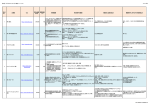
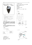
取扱説明書 MODEL TW-4M-N(UW-47564a)
ユニバーサル直流信号変換器
MODEL TW-4M-1-N,TW-4M-4-N
1 . 出 荷 時 レ ン ジ 設 定 : 入力1−5V、出力4−20mA
M3.5×7L
2.推奨圧着端子:
丸形M3.5用外径6.6以下
U 形 M 3 . 5 用 幅 6 .2 以 下
3.材質:結線ビス 導電板 2 . 入 力 レ ン ジ 設 定 変 更 誤 差 :±1%F.S以下
出 力 レ ン ジ 設 定 変 更 誤 差 :±1%F.S以下
3 . 温 度 特 性 : ±0.02%F.S/℃
誤った取り扱いをすると、死亡又は重傷を
負う可能性が想定される場合に示します。
5 . 絶 縁 抵 抗 : 入力−出力−電源各間 100MΩ以上(DC500V)
注 意
電
圧 :入力−出力−電源各間 AC2000V 1分間 ■概 要
またはDC24V±10%
1 2 . ケ ー ス 材 質 : 黒色PBT 94−V0
量 : 約130g
■入出力接続図
3
7
−
電源
( AC )
電源
( DC )
+
TW-4M
1
6
−
5
+
信号
出力
仕様と比べ御確認ください。
ON
OFF
0−10V
ON
OFF
0−60mV
ON
OFF
1−5V
ON
OFF
−5∼5V
ON
OFF
−10∼10V
ON
OFF
0−20mA
ON
OFF
4−20mA
ON
OFF
注 )接 続 極性 に 注意 し て下 さ い。
電源指定コード
4.DC24V±10%
■入力仕様 直流電圧・電流
入力
回路
DC0∼10V
−50∼
■外形寸法図
96∼98スライド
DC0∼20mA
DC4∼20mA
250Ω
正面図
48
DC−10∼10V
入出力レンジ
設定用
ディップスイッチ
DC−5∼5V
出力レンジ
設定用
ディップスイッチ
+150%F.S
1MΩ以上
ZERO/SPAN
調整用ボリューム
DC1∼5V
7( ∼ ), (+ )
電 源
8( ∼ ), (− )
電
源
回
路
DC0∼5V
DC0∼60mV
5 (+ )
出 力信 号
6 (− )
出力
回路
入力許容値
入力抵抗値
■出力仕様 直流電圧・電流
出力信号
DC0∼5V
許容負荷抵抗
64.5
2kΩ以上
94
DC1∼5V
DC−5∼5V
DC4∼20mA
DC0∼20mA
550Ω以下
側面図
SW2
SW2
MORMAL
REVERS
ON
OFF
12345678
SW3
ON
OFF
0−20mA
ON
OFF
0−10V
ON
OFF
4−20mA
ON
OFF
1−5V
ON
OFF
−5∼5V
ON
OFF
−10∼10V
ON
OFF
ながら、下側をレールよりはずす。
■注意事項
ON
OFF
0−5V
1 マイナスドライバー等でスライダーを押し下げ
2 上側をレールよりはずす。
ON
OFF
12345678
・保存温度−10∼+70℃以内、湿度60%以下の
範囲で保存して下さい。
・ちり・ゴミ・電気部品に有害な化学薬品・ガス類等
のない場所でご使用ください。
・振動・衝撃がかからない様にしてください。
・ノイズ等の影響を減らすために入出力配線を電源配線
と同一結束・同一ダクト内で使用することは避けて
下さい。
■保 証
12345678
5、高精度の測定を行う為、入出力レンジの設定・変更後(設定が
正しいことを、もう一度確認してから)出力のゼロ−スパン
調整を行ってください。
・ゼロ調整
入力端子に入力の最小値を入力し、このときの出力が出力仕様の
最小値となる様にZEROボリュームを廻してください。
・スパン調整
入力端子に入力の最大値を入力し、このときの出力が出力仕様の
最大値となる様にSPANボリュームを廻してください。
上記のゼロ調整、スパン調整を1∼2回繰り返して、入力を
最小と最大に切り換えた時に、出力が出力仕様に入るように
してください。
6、本変換器の上面に、SW1,SW2,SW3の設定一覧があ
りますので、設定された入出力仕様を油性マジックペンにて
チェックしておくと便利です。
電子計測事業部
35.2
35.4
旭 計 器 株 式 会 社
4.5
DC−10∼10V
3、リバ−ス(出力反転)の設定・変更
本器の保証期間は納入日より1ヶ年です。この期間中に
発生した事故で明らかに弊社が原因と判断される場合
は無償で修理又は新品と交換させて頂きます。
■アフターサービス
本製品は厳正な品質管理のもとで製造、試験、検査を
して出荷しておりますが、万一故障した場合は取扱店、
又は直接弊社へご連絡(送付)下さい。故障内容は
出来るだけ詳しくメモされ、現品と同封していただけ
ると幸いです。
■付 属 品
ディップスイッチシール ×2
取扱説明書 ×1
旭計器株式会社
41
4kΩ以上
17.4
DC0∼10V
2
12345678
SW3
20
入力信号
3 (+ )
入力 信 号
4 (− )
1
4、出力レンジの設定・変更
絶縁 ア ンプ Z ER O S PA N
1.AC100∼240V±10%
(フェニックス製 E/NS35N 等)
を避けてください。
12345678
■ブロック図
れる事をお勧めします。
■取り外し
ON
OFF
TW−4M−□−N
※取付後にずれるおそれがある時は、止め金具を使用さ
SW2
2、応答速度の設定・変更
50mS
500mS
■型式の構成
本器の各コードと標準仕様は次の通りです。先ずご注文の
0−5V
1 上側をレールにかける。
2 下側を押し込む。
2台以上並べて使用される時は、間隔をあけて、密着
1234
2
SW3
ON
OFF
SW1
1 1 . 保 管 湿 度 : 60%RH以下(結露無きこと)
∼
SW2
1、入力レンジの設定・変更
1 0 . 保 管 温 度 : −10∼+70℃以内
入力を絶縁して、直流電圧・電流に変換して出力する変換器です。 信 号
入力設定用ディップスイッチ及び出力設定用ディップスイッチにて 入 力 +
入出力の設定及び変更が可能です。
また、入力・出力・電源の3ポートが絶縁されており、ケースは
DINレールにワンタッチで取付可能です。
入出力端子にはM3.5用ねじ端子台を採用しています。
SW1
工場出荷時
9 . 動 作 周 囲 湿 度 :90%RH以下(結露無きこと)
8
入出力レンジの設定と変更は、変換器上面のディップスイッチ
ます。
8 . 動 作 周 囲 温 度 :−5∼+50℃
4
2
必ず電源OFFの状態で操作を行ってください。
ください。
工場出荷時は、入力1−5V、出力4−20mAに設定されてい
80mA以下(atDC24V)
−
!
設定終了後ディップスイッチ操作窓に添付のシールを貼り付けて
消 費 電 流 : 50mA以下(atAC100V)
ユニバーサル直流信号変換器TW−4Mは直流電圧・直流電流
黄銅、半田メッキ
SW1,SW2,SW3 にて行います。
7 . 電 源 電 圧 : AC100∼240V±10%
13. 質
1
鉄、ニッケルメッキ
■入出力レンジの設定と変更
4 . 応 答 時 間 : 50msec以下(規定出力の90%に至る時間)
6.耐
■取り付け
1.結線ビスサイズ:
出 荷 時 レ ン ジ 設 定 許 容 差 :±0.25%F.S以下
取扱説明書
(1)入力に最大許容値を超える電圧や電流を加えると,機器の
破損につながります。
(2)電源電圧は使用可能範囲内で使用してください。使用可能
範囲外で使用しますと火災・感電・故障の原因となります。
(3)本書の内容に関しては製品改良の為予告なしに変更するこ
とがありますのでご了承ください。
(4)本書の内容については万全を期して作成しましたが,万一
ご不審な点や誤り,記載もれなど,お気付きのことがあり
ました場合は、取扱店または直接弊社へご連絡ください。
(5)本書をお読みになった後は,いつでも見られる場所に必ず
保存してください。
■取り付け・取り外し方法
■ねじ端子台接続圧着端子について
■一般仕様
(1/2)
Homepage URL:http://www.asahikeiki.co.jp/
本社 〒146-8505 東京都大田区矢口2-33-6
TEL 03(3759)6171(代表)
東京営業所
03(3759)6177(営業ダイヤルイン)
FAX 03(3757)2989(営業直通)
大阪営業所 〒564-0053 大阪府吹田市江の木町17−1
江坂全日空ビル4階1号室
TEL 06(6310)8565(営業ダイヤルイン)
FAX 06(6310)8500
名古屋営業所 〒465-0025 名古屋市名東区上社4-29-1
TEL 052(701)9671(営業ダイヤルイン)
FAX 052(701)9700
INSTRUCTION MANUAL MODEL TW-4M-N(UW-47564a)
UNIVERSAL ISOLATE TRANSDUCER
MODEL TW-4M-1-N,TW-4M-4-N
INSTRUCTION MANUAL
This marking indicates that the
erroneous operation of this
transducer may result in death or
serious injury.
Precautions
(1)If voltage or current exceeding the allowable maximum
voltage or current is applied to the input terminals,
the transducer may be damaged.
(2)Apply power within the applicable range of the
transducer. Otherwise fire, electric shock or
transducer damage may result.
(3)The contents of this instruction manual are subject
to change without prior notice.
(4)This instruction manual is carefully prepared.
However, if any mistake or omission is found, contact
your nearest Asahi sales agent or Asahi directly.
(5)Make this manual available easily anytime.
■ General specifications
1.Range settings before shipment:
Input; 1 to 5 VDC , output; 4 to 20 mADC
Accuracy of range settings before shipment: Within ±0.25% F.S
2.Error caused by input range setting change: Within ±1% F.S
Error caused by output range setting change: Within ±1% F.S
3.Temperature characteristic:±0.02% F.S/℃
4.Response time:
Less than 50ms (Time repuired for arriving at 90% of rated output)
5.Insulation resistance:
Between input and output or power supply, More than 100 MΩ
(At 500 VDC)
6.Dielectric strength:
Between input and output or power supply, For 1 min. (At 2000VAC)
7.Power supply voltage:
100 to 240 VAC ±10% or 24 VDC ±10%
Consuming current:
Less than 50mA (At 100 VAC)
Less than 80mA (At 24 VDC)
8.Operating ambient temperature:-5 to +50℃
9.Operating humidity: Less than 90% RH (No dew-condensing)
10.Storage temperature: -10 to +70℃
11.Storage humidity: Less than 60% RH (No dew-condensing)
12.Case material: Black PBT 94-V0
13. Weight: Approx. 130g
■ Input/output connection diagram
■ Outline
In put−
This Model TW-4M universal isolate transducer is used to
sig
na l
convert DC voltage/current input into DC voltage/current
+
output isorated from the input. The input/output can be
set or changed by input/output setting dip switches.
In addition, the three ports of input, output and power
are mutually isolated. The case can be mounted on a DIN
rail in one touch. 4p screw type terminal blocks are used for
the input and output.
■ Model No. Configuration
Each code and the standard specifications of this
transducer are as follows. First check whether or not your
desired specifications are correct by comparing them to
the following specifications.
TW−4M−□−N
Code to
specify power
1.100 to 240 VAC ±10%
4.24 VDC ±10%
4
8
3
7
∼
−
Po we r
(DC )
+
Po we r
(A C)
TW-4M
6
−
1
5
+
Ou tp ut
si gn al
I so lat io n A mp
3( + )
In pu t sig na l
4( − )
In pu t
ci rc uit
O utp ut
c irc ui t
250 Ω
Sliding from 96 to 98
20
■ Dimensions
-50 to +150% F.S
■ Output specification DC voltage/current
VDC
VDC
VDC
VDC
VDC
mADC
mADC
94
More than 2 kΩ
Less than 550 Ω
ON
OFF
1−5V
ON
OFF
−5∼5V
ON
OFF
−10∼10V
ON
OFF
0−20mA
ON
OFF
4−20mA
ON
OFF
*If the transducer is likely to be dislocated after its mounting,
it is recommended that a clamp be used.
(For example E/NS35N made by PHOENIX CONTACT)
If two or more transducers are mounted in a row, do not contact
each transducer, but leave some space between each transducer.
1
2
1 Push down the slider with a screwdriver.
Push up the bottom side of the transducer.
1234
50mS
500mS
1 Engage the top side of the transducer with the rail.
2 Push the bottom side of the transducer into the rail.
12345678
2 Disengage the top side of the transducer from the rail.
3. Setting Revers (Output)
ON
OFF
SW2
MORMAL
REVERS
ON
OFF
ON
OFF
ON
OFF
12345678
4. Setting or changing output range
SW3
ON
OFF
0−10V
ON
OFF
0−20mA
ON
OFF
1−5V
ON
OFF
4−20mA
ON
OFF
5 ( +)
O utp ut s ign al
−5∼5V
ON
OFF
6 ( −)
3. As this transducer is used for high-accuracy measurement,
after setting or changing the input/output range (after
re-checking that the setting is correct), make output
ZERO and SPAN adjustments.
・ZERO adjustment
Apply the minimum input value to the input terminals.
Then, turn the ZERO adjuster until the output at this time
becomes the minimum value in the output specification.
・SPAN adjustment
Apply the maximum input value to the input terminals.
Then, turn the SPAN adjuster until the output at this time
becomes the maximum value in the output specification.
Repeat the above ZERO and SPAN adjustments several times
until the minimum output value in the output specifications
is obtained at the minimum input value and also the maximum
output value in the output specification is obtain at the
maximum input value.
4. There is a list of the INPUT and OUTPUT signals as well as
SW1 and SW2,SW3 on top of the transducer. Therefore it is
convenient to put check marks on the input/output
12345678
12345678
■ Caution
・Store the transducer at a location having a storage temperature
of -10 to +70℃ and a humidity of less than 60% RH.
・Use the transducer at a location where there are no chemicals
or gases harmful to its electrical parts or there is no dust.
・Do not apply any vibration or impact to the transducer.
・In order to lessen the effect of noise, etc., do not bundle the
input/output wires with the power supply wires, nor put these
wires in the same duct.
■ Warranty
This transducer is warranted for a period of one year from date of
delivery. Any defect which occurs in this period and is undoubtedly
caused by Asahi's faults will be remedied free of charge. This
warranty does not apply to the transducer showing abuse or damage
which has been altered or repaired by others except as authorized
by Asahi Keiki Co., Ltd.
■ After-sale service
This transducer is delivered after being manufactured, tested and
inspected under strict quality control. However, if any problem
does occur, contact your nearest Asahi sales agent or Asahi
directly giving as much information on problem as possible.
■ Accessories
Dip switch seal
Instruction Manual
2 sheet
1 pcs.
ASAHI KEIKI CO., LTD.
Side view
More than 4 kΩ
35.2
35.4
ASAHI KEIKI CO., LTD.
4.5
5
5
-5
10
10
20
20
64.5
41
to
to
to
to
to
to
to
Allowable load
resistance
17.4
0
1
-5
0
-10
0
4
0−60mV
−10∼10V
7 ( ∼) (+ )
P owe r
8 ( ∼) (− )
P owe r cir cu it
Front view
Output signal
ON
OFF
ON
OFF
Z ER O S PA N
Input allowable
range
More than
1 MΩ
0−10V
2
SW2
SW3
I/O range
setting
Dip SWs.
VDC
VDC
mVDC
VDC
VDC
VDC
mADC
mADC
ON
OFF
1
■ Dismounting
0−5V
■ Block diagram
ZERO/SPAN
adjusters
5
10
60
5
-5
10
20
20
SW1
0−5V
■ Mounting
SW3
SW2
Note:When conducting wiring, be careful with its polarity.
I/O range
setting
Dip SWs.
to
to
to
to
to
to
to
to
SW2
12345678
48
0
0
0
1
-5
-10
0
4
Input
resistance
SW1
Range settings ON
before shipment OFF
1. Setting or changing input range
2. Setting Speed
2
■ Input specification DC voltage/current
Input signal
■ About solderless terminal to connect with the screw type
terminal block
1.Screw size: M3.5×7L
2.Recommendation solderless terminal: Ring tongue(R type) M3.5
Spade tongue(A type)M3.5
Applicable Wire AWG# 26to22
3.Quality of material: Screw Iron,nickel plating
Connection board
Yellow copper,solder plating
■ Setting or changing input/output range
Always set or change the input/output range with
the power turned off.
The input/output range can be set or changed by dip
switches SW1 and SW2,SW3 on top of the transducer.
After finishing the setting, stick the attached seal to the
window for dip switch operation. Prior to factory shipment,
the input is set 1 to 5 V and the output, 4 to 20 mA.
(2/2)
ELECTRONIC DEPT.
33-6 YAGUCHI 2-CHOME, OHTA-KU, TOKYO 146-8505, JAPAN
PHONE:81-3-3759-3893
Homepage URL:http://www.asahikeiki.co.jp/
FAX :81-3-3757-2989
e-mail:[email protected]