Transcript
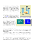
取扱説明書 ACD・ACS
Instruction manual
取り付けについて
About installation
Cleaning of shaft surface. Clean the shaft surface of dust and rust.
取り外し
How to install
ACD・ACSシリーズは出荷時、専用の治具にて左右のフランジの同心
を調整しておりますのでカップリングを基準にして簡易的な偏心、偏角
を確認して下さい。
ACD・ACS series has been shipped after adjusting concentricity or right and
left flange by special jig, therefore confirm the off centering and misangle
based on coupling.
心出し精度について
About off centering.
2軸間のミスアライメントをカップリングの許容値以下になる様、心出
しを実施して下さい。
2軸間のミスアライメントが大きい場合、振動や異音の発生、又は寿命
に大きな影響を与える事がありますので、正確に実施して下さい。
Safety before uninstallation.
ACの駆動軸を締結(従動側は締結せず)して回転させ、カップリング
がストレスなくスムーズに回転する事を確認して下さい。
(Fig.4)
ロックボルトを緩める前に安全確認を行い、作業を始めて下さい。
動力源(電源)を切り、カップリングにトルク・スラスト力等が加わって
いないか、落下等の危険がないかを確認して下さい。
Connect to the driven shaft and rotate without connecting the follow shaft for
checking coupling rotation without any stress. (Fig.4)
The clamping screws must not loosen for installation, which are tightened by
standard torque. If clamping screws are loosen, then this causing a damage to
disk spring.
ロックボルトを緩めると軸クランプが解かれ取り外しが
可能となります。
Loosen the locking screw for releasing from the shaft.
①ACを駆動側の軸に挿入し、次に従動側の軸を挿入します。
(Fig.2)
Install one side of shaft (driven shaft) and install the other shaft (follow shaft)
(Fig.2)
参考資料
※挿入の際、従動軸でARを押さない様に慎重に挿入して下さい。
(ディスク
がズレて使用出来なくなります。)
従動軸
Do not push the AC coupling by follow shaft at installation. (This cause of
dislocation of disk spring.)
モータ軸心の確認
Confirmation of center
of motor shaft
駆動軸
Follow shaft
Shaft installation amount.
After the positioning of AR coupling, tightening the locking screw by torque
wrench with standard torque. Use the torque wrench for tightening the locking
screw.
④組付け確認
モータ
駆動軸
Follow shaft
Driven shaft
Motor
Fig.1
①モータ出力軸の振れ精度の確認をします。
従動軸
Follow shaft
駆動軸
Driven shaft
Fig.2
②簡易偏心・偏角の確認
Simple confirmation of off centering and misangular.
Confirmation of installation
サイドから目視してディスクにゆがみがないか確認して下さい。
カップリング全長寸法を測定して、過大な偏角がカップリングにかかっ
ていないかを目安として測定して下さい。
(Fig.5)
Confirm the straightness of disk spring by sight from side. Inspect and measure
the length of coupling, if there is large misanglar on it. (Fig.5)
Check the off centering accuracy of output motor shaft.
Find the centering accuracy by measuring the output motor shaft before
coupling installation.
Set the dial gauge as picture for measuring the off centering of motor shaft.
(Fig.1)
※モータの軸振れ量は各社にて規定されておりますが、
この状態で心ズレを
起こしている可能性があります。
Off centering amount of motor shaft is established by each manufacturer,
however at this stage off centering might be already occurred.
Type
How to check the off centering.
ACを軸 方向にスライドさせてスムーズに動く事 を確 認して下さい。
(Fig.3)
Slide the AC coupling to thrust direction and check this movement has no
stress. (Fig.3)
※スライド時抵抗がある場合、モータ軸の様に軸の微調整が可能なときはモ
ータの締め付けボルトにて心出し調整を行って下さい。
軸の移動が出来ない場合、加工精度・組立精度により両軸の心出しを行っ
て下さい。
Adjust the off centering with tightening screw, if there is the stress at sliding. If
shaft sliding is impossible then high accuracy processing and assembly is
required for centering.
Type
Refer the table below for shaft installation
amount and design (Fig.6)
※軸挿入量は締結方法(キーまたはセット
スクリュー)が変わって、同じ最小挿入
寸法となります。
Type
L1
(mm)
(N・m)
(M)
(M)
7.8
0.4
2
3
9
1.0
2.6
̶
10
1.5
3
̶
インサイドクランプ テーパアタッチメント
ACD・ACS-34A
ACD・ACS-39A
12
3.5
4
̶
25.7
̶
ACS-19A
16.9
̶
ACD・ACS-44A
13
3.5
4
̶
ACD-27A
31.6
̶
ACS-27A
19.3
̶
ACD・ACS-55A
5
̶
ACD-34A
37
̶
ACS-34A
21.8
̶
ACD-39A
45
̶
ACS-39A
26.5
̶
ACD-44A
48
̶
ACS-44A
28.5
̶
ACD-56A
58.6
72.6
ACS-55A
34.8
58.8
Type
ACS Series
L
Driven shaft
軸径
キー幅
Shaft
diameter
Key groove
width
φ
mm
6
2
8・10
3
6
2
8・10
3
11・12
4
14・15
5
キー幅の
許容差
Allowable
tolerance
of key width
深さ
Depth
mm
mm
±0.0125
±0.0125
±0.0150
1.4
(M)
標準寸法
Standard size
7.5
ACD-27A
11
AD
2
1.4
1.0
2
2
+0.1
0
AL
2
1.8
3
2.3
4
Minimum size
最大可能寸法
Maximum size
6.3
10
9.4
15
ACD-34A
13.4
11.4
20
ACD-39A
16
13.4
24
ACD-44A
17
13
25
ACD-56A
21
17.4
31
E
MJ
単位 Unit:mm
最小可能寸法
AHT
AS
リジッドタイプ
ACD-19A
Fig.5
mm
AHS
Set screw
diameter of key
connection type
L3寸法適用表
Type
Taper attachment
Allowable
tolerance of
depth
1.0
L3 Size Application Table
テーパアタッチメント
深さの キー止めセット
許容差 スクリュー径
オルダムタイプ
ACSシリーズ
L
7
Key groove width, depth, and set screw diameter for key connection type.
型 式
L
L
16
ACS
AHD
キー仕様のキー幅・深さ、キー止めセットスクリュー径
型 式
101
セット
ACD・ACS-27A
Inside clamping Taper attachment
ACD Series
駆動軸
サイドクランプ
ACD-19A
Inside clamping Taper attachment
ACDシリーズ
Fig.3
締付トルク
ACD・ACS-19A
ACD・ACS-34A
従動軸
最小挿入寸法
ACD
Fig.6
Minimum shaft
ボルトサイズ スクリュー径
installation amount Tightening torque Side clamping screw size Set screw diameter
型 式
ACD・ACS-27A
Follow shaft
L1
The install amount should be still the
same even connection has changed. 全長 L寸 Length L
mm
型 式
インサイドクランプ テーパアタッチメント
カップリングへの軸挿入 量は下表を
参照し設計して下さい。
(Fig.6)
フレキシブルタイプ
カップリングを取り付けるモータ出力軸の振れを測定する事により、心
出し精度の基準値を把握し、カップリングの組み付けを開始します。
図の様にモータ軸にダイヤルゲージを当て、振れ量を確認して下さい。
(Fig.1)
型 式
簡易偏心の確認方法
全長 L寸 Length L
mm
Reference
軸挿入量
Driven shaft
Fig.4
③ACの位置決め完了後ロックボルトをトルクレンチにより規定のトルク
にて締付けを行って下さい。
締め付けは必ずトルクレンチにて所定のトルクで締め付けて下さい。
従動軸
Check your safety first before loosening the locking screws. Turn off the main switch, check thrust load and torque are not on coupling or
check the drops.
選定設計
ラインアップ 使用実例
取扱説明
ガイド
Use example Guidance for Installation
selection
manual
and design
Set the misalignment between 2 shafts within coupling capacity.
If the misalignment is large between 2 shafts, vibration, noise will occur and
effect for product durability.
Our coupling is adjusted in center by installation jig before shipping from our
factory, therefore coupling should be installed without loosening the clamping
screw.
取リ外し前の安全対策
How to check misangle.
Lineup
弊社のカップリングは組み付け治具により、同心調整後出荷しておりま
すので、クランプボルトは緩めず組み付けを行なって下さい。
※ACはクランプボルトを所定のトルクで締め付けて出荷していますのでボ
ルトを緩めないで下さい。同心が崩れてディスク等の破損につながる可能
性があります。
簡易偏角の確認方法
Uninstallation
カップリング
軸表面のゴミ、サビ、汚れ等を拭き取って下さい。
組付け手順
JK
JKW
N
102