1
TRINITRON® COLOR VIDEO MONITOR
BVM-A20F1U
BVM-A20F1M
BVM-A20F1A
電気製品は、安全のための注意事項を守らないと、
火災や人身事故になることがあります。
このオペレーションマニュアルには、事故を防ぐための重要な注意事項と製品
の取り扱いかたを示してあります。このオペレーションマニュアルをよくお読
みのうえ、製品を安全にお使いください。お読みになったあとは、いつでも見
られるように必ず保管してください。
OPERATION MANUAL [Japanese/English]
1st Edition (Revised 3)
Serial No. 2000001 and Higher
日本語
安全のために
ソニーのモニターは正しく使用すれば事故が起きないように、安全には十分配慮し
て設計されています。しかし、内部に非常に高い電圧を使用しているので、まち
がった使いかたをすると、火災や感電などにより死亡や大けがなど人身事故につな
がることがあり、危険です。
事故を防ぐために次のことを必ずお守りください。
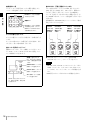
警告表示の意味
このオペレーションマニュアルお
よび製品では、次のような表示を
しています。表示の内容をよく理
解してから本文をお読みください。
安全のための注意事項を守る
5 ∼ 7 ページの注意事項をよくお読みください。製品全般の安全上の注意事項が記
されています。8 ページの「使用上のご注意」もあわせてお読みください。
定期点検をする
5 年に 1 度は、内部の点検を、お買い上げ店またはソニーのサービス窓口にご依頼
この表示の注意事項を守らないと、
火災や感電などにより死亡や大け
がなど人身事故につながることが
あります。
ください(有料)。
故障したら使わない
すぐに、お買い上げ店またはソニーのサービス窓口にご連絡ください。
万一、異常が起きたら
• 異常な音、におい、煙が出たら
この表示の注意事項を守らないと、
感電やその他の事故によりけがを
したり周辺の物品に損害を与えた
りすることがあります。
注意を促す記号
• 内部に水、異物が入ったら
• モニターを落としたり、キャビネットを破損したときは
m
a 電源を切る。
b 電源コードや接続ケーブルを抜く。
c お買い上げ店またはソニーのサービス窓口に連絡する。
行為を禁止する記号
行為を指示する記号
2
安全のために
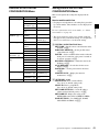
目次
警告 ................................................................................................................................. 5
注意 ................................................................................................................................. 6
使用上のご注意(モニターの性能を保持するために).......................................................... 8
第 1 章 概要
特長 ........................................................................................................................................ 9
特長............................................................................................................................. 9
別売り品 ................................................................................................................... 10
入出力端子パネルの構成 .......................................................................................... 11
入力アダプターの装着.............................................................................................. 12
各部の名称と働き ................................................................................................................ 13
モニター前面 ............................................................................................................ 13
モニター背面 ............................................................................................................ 14
モニターコントロールユニット BKM-15R(別売り)............................................... 16
“メモリースティック”の取り扱い .......................................................................... 21
JP
“メモリースティック”について.............................................................................. 21
4:3 マスクの取り付け ...................................................................................................... 23
接続 ...................................................................................................................................... 24
BKM-15R との接続................................................................................................... 24
ネットワーク接続 ..................................................................................................... 24
モニター / グループの選択.................................................................................................. 26
基本設定の選択.................................................................................................................... 27
第 2 章 メニュー
メニューの操作方法............................................................................................................. 28
メニュー操作ボタン ................................................................................................. 28
メニューを表示させるには....................................................................................... 29
メニューの操作手順 ................................................................................................. 29
メニューの階層構造............................................................................................................. 32
[A] 画像の調整 − PICTURE ADJ メニュー ..................................................................... 34
概要........................................................................................................................... 34
PICTURE ADJ メニューの階層構造........................................................................ 34
構成メニュー ............................................................................................................ 34
[B] 色温度の調整 ー COLOR TEMP ADJ メニュー ......................................................... 36
概要........................................................................................................................... 36
COLOR TEMP ADJ メニューの階層構造 ............................................................... 37
構成メニュー ............................................................................................................ 37
目次
3
[C] 入力チャンネルの設定 − INPUT CONFIGURATION メニュー.................................40
概要 ...........................................................................................................................40
INPUT CONFIGURATION メニューの階層構造 ....................................................41
構成メニュー.............................................................................................................41
[D] システムの設定 − SYSTEM CONFIGURATION メニュー .......................................45
概要 ...........................................................................................................................45
SYSTEM CONFIGURATION メニューの階層構造.................................................46
構成メニュー.............................................................................................................46
[E] 設置調整− INSTALLATION SETTINGS メニュー....................................................49
概要 ...........................................................................................................................49
INSTALLATION SETTINGS メニューの階層構造.................................................50
構成メニュー.............................................................................................................50
[F] システムデータの操作− FILE MANAGEMENT メニュー ..........................................54
概要 ...........................................................................................................................54
FILE MANAGEMENT メニューの階層構造 ...........................................................54
構成メニュー.............................................................................................................54
[G] モニターに関する情報の表示 − STATUS メニュー ...................................................56
概要 ...........................................................................................................................56
STATUS メニューの階層構造 ..................................................................................56
構成メニュー.............................................................................................................57
[H] コントローラーの設定 − CONTROLLER メニュー ....................................................58
概要 ...........................................................................................................................58
CONTROLLER メニューの階層構造........................................................................58
構成メニュー.............................................................................................................58
[I] キーロック設定 − KEY PROTECT メニュー ...............................................................59
概要 ...........................................................................................................................59
構成メニュー.............................................................................................................59
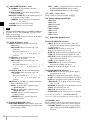
付録
仕様.......................................................................................................................................60
対応信号システム ....................................................................................................................................................... 62
対応信号フォーマット............................................................................................................................................. 63
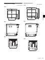
外形寸法図........................................................................................................................................................................ 65
色温度調整用プローブを使用するときの接続ケーブルについて........................................... 66
メニュー項目索引 .................................................................................................................68
4
目次
警告
規定の電源電圧で使う
取扱説明書に記されている電源電圧でお
使いください。
規定外の電源電圧での使用は、火災や感
電の原因となります。
油煙、湯気、湿気、ほこりの
多い場所では設置・使用しな
い
内部を開けない、改造しない
上記のような場所に設置すると、火災や
感電の原因となります。
内部には電圧の高い部分があり、キャビ
ネットや裏ぶたを開けたり、改造したり
取扱説明書に記されている仕様条件以外
の環境での使用は、火災や感電の原因と
すると、火災や感電の原因となることが
あります。内部の調整や設定、点検、修
なります。
理は、お買い上げ店またはソニーのサー
ビス窓口にご依頼ください。
高圧に注意する
内部に水や異物を入れない
サービス担当者以外の方は裏ぶたをあけ
ないでください。内部には高電圧部分が
数多くあり、万一さわると危険です。
水や異物が入ると火災や感電の原因とな
ります。
万一、水や異物が入ったときは、すぐに
電源を切り、電源コードや接続ケーブル
を抜いて、お買い上げ店またはソニーの
サービス窓口にご相談ください。
電源コードを傷つけない
電源コードを傷つけると、火災や感電の
原因となることがあります。
• 設置時に、製品と壁やラック、棚など
の間に、はさみ込まない。
• 電源コードを加工したり、傷つけたり
しない。
• 重いものをのせたり、引っ張ったりし
ない。
• 熱器具に近づけたり、加熱したりしな
い。
安全アースを接続する
安全アースを接続しないと、感電の原因
となることがあります。
次の方法でアースを接続してください。
• 電源コンセントが 3 極の場合
付属の電源コードを使用することで安
全アースが接続されます。
• 電源コンセントが 2 極の場合
付属の 3 極 t 2 極変換プラグを使用
し、変換プラグから出ている緑色の
アース線を建物に備えられているアー
ス端子に接続してください。
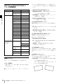
変換プラグアダプター
• 電源コードを抜くときは、必ずプラグ
を持って抜く。
万一、電源コードが傷んだら、お買い上
げ店またはソニーのサービス窓口に交換
をご依頼ください。
アース線
安全アースを取り付けることができない
場合は、ソニーのサービス担当者または
営業担当者にご相談ください。
警告
5
注意
背面の放熱板には触れない
モニター使用中は、セット背面の放熱板
が高温になっています。触れると火傷の
恐れがありますのでご注意ください。
重いモニターは、2人以上で
開梱・運搬する
指定された電源コード、接続
ケーブルを使う
モニターは見た目より重量があります。
開梱や運搬は、けがや事故を防ぐため、
必ず 2 人以上で行ってください。1 人で
行うと腰を痛めることがあります。
付属の、あるいは取扱説明書に記されて
いる電源コード、接続ケーブルを使わな
いと、感電や故障の原因となることがあ
ります。
他の電源コードや接続ケーブルを使用す
る場合は、お買い上げ店またはソニーの
サービス窓口にご相談ください。
ぬれた手で電源プラグをさわ
らない
ぬれた手で電源プラグを抜き差しする
と、感電の原因となることがあります。
通気孔をふさがない
転倒、移動防止の処置をする
通気孔をふさぐと内部に熱がこもり、火
災や故障の原因となることがあります。
モニターをラックに取り付け・取りはず
風通しをよくするために次の項目をお守
りください。
• 壁から 10cm 以上離して設置する。
• 密閉された狭い場所に押し込めない。
• 毛足の長い敷物(じゅうたんや布団な
ど)の上に設置しない。
• 布などで包まない。
• あお向けや横倒し、逆さまにしない。
不安定な場所に設置しない
ぐらついた台の上や傾いたところなどに
設置すると、モニターが落ちたり、倒れ
しするときは、転倒・移動防止の処置を
しないと、倒れたり、動いたりして、け
がの原因となることがあります。
安定した姿勢で注意深く作業してくださ
い。
また、ラックの設置状況、強度を充分に
お確かめください。
製品の上に乗らない、重い物
を乗せない
倒れたり、落ちたり、壊れたりして、け
がの原因となることがあります。
たりして、けがの原因となることがあり
ます。また、設置・取り付け場所の強度
を充分にお確かめください。
直射日光の当たる場所や熱器
具の近くに設置・保管しない
内部の温度が上がり、火災や故障の原因
となることがあります。
真夏の、窓を閉め切った自動車内では
50 ℃を越えることがありますので、ご
注意ください。
6
注意
お手入れの際は、電源を切っ
て電源プラグを抜く
電源を接続したままお手入れをすると、
感電の原因となることがあります。
接続の際は電源を切る
コード類は正しく配置する
電源コードや接続ケーブルを接続すると
電源コードや接続ケーブルは、足に引っ
きは、電源を切ってください。さもない
と感電や故障の原因となることがありま
かけると本機の落下や転倒などによりけ
がの原因となることがあります。
す。
十分注意して接続・配置してください。
移動の際は電源コードや接続
コードを抜く
コード類を接続したまま本機を移動させ
ると、コードに傷がついて火災や感電の
原因となることがあります。
定期的に内部の掃除を依頼す
る
長い間掃除をしないと内部にホコリがた
まり、火災や感電の原因となることがあ
ります。1 年に 1 度は、内部の掃除をお
買い上げ店またはソニーのサービス窓口
にご依頼ください(有料)
。
特に、湿気の多くなる梅雨の前に掃除を
すると、より効果的です。
入力アダプター及びコント
ロールユニット取り付けの際
には、電源を切って電源プラ
グを抜く
電源コードのプラグ及びコネ
クターは突き当たるまで差し
込む
真っ直ぐに突き当たるまでさしこまない
と、火災や感電の原因となります。
密閉環境に設置する際は注意
する
本機をラックやモニター棚に収納した
際、上下および周辺の機器によりモニ
ター周辺の通気孔が妨げられ動作温度が
上がり、故障や発熱の原因となる可能性
があります。本機の動作条件温度 0 ℃か
ら 35 ℃を保つように上下および周辺機
器との隙間を十分にとり、通気孔の確保
や通気ファンの設置などの配慮をしてく
ださい。
モニターを電源に接続したまま各種入力
アダプターおよびコントロールユニット
の取り付けを行うと、感電の原因になる
ことがあります。入力アダプター及びコ
ントロールユニットの取り付けの際には
モニターの電源を切り、電源プラグを抜
いてください。
基板の取り付けは注意深く
各種入力アダプターを取り付ける際には
部品や基板の角などで手や指にけがをす
ることがあります。保護手袋などをして
注意深く作業してください。
注意
7
4:3 信号用のモニターとしてお使いになるときのご注意
使用上のご注意(モニターの性能
を保持するために)
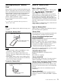
磁気に対するご注意
• 磁石、スピーカー、電気時計、磁石を使用した機器やお
もちゃ、磁気応用健康器具など、磁気を発生するものを
近づけないでください。磁気の影響を受けて、画面が揺
れたり、色が乱れたりすることがあります。
• モニターの設置の向きによっては、地磁気の影響を受け
て、画面が傾いたり、色が乱れることがありますが、故
障ではありません。このときは、モニターコントロール
ユニットの DEGAUSS(消磁)ボタンを押して消磁して
ください。
ラックに収納する場合のご注意
本機をラックやモニター棚に収納した際、上下および周辺
の機器によりモニター周辺の通気孔が妨げられ動作温度が
上がり、故障や発熱の原因となる可能性があります。本機
の動作条件温度 0 ℃から 35 ℃を保つように上下に 1U の隙
間をあけ、また周辺機器との隙間を十分にとり、通気孔の
確保や通気ファンの設置などの配慮をしてください。
ブラウン管について
• ブラウン管の表面はほこりが付きやすいので、ときどき
柔らかい布でふいてください。また、表面は傷つきやす
いので、硬いものでこすったり、たたいたり、ものをぶ
つけたりしないでください。
• ブラウン管の表面に手を触れると弱い電気を感じること
がありますが、これはブラウン管表面に静電気を帯びて
いるためで、人体に影響はありません。
クリーニングについて
• お手入れの際は、必ず電源を切って電源プラグを抜いて
ください。
• キャビネットの汚れがひどいときは、水で 5 ∼ 6 倍に薄め
た中性洗剤液に柔らかい布をひたし、かたくしぼってか
ら汚れをふきとります。このあと乾いた布でからぶきし
てください。
• シンナーやベンジンなどの薬品類は、表面の仕上げをい
ためたり、表示が消えてしまうことがありますので、使
用しないでください。
8
使用上のご注意(モニターの性能を保持するために)
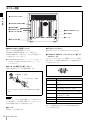
本機には出荷時に 16:9 マスクが取り付けてあるため、本機
の 16:9 ボタンを操作して 4:3 アスペクト表示にすると、画
像の上部と下部がマスクに隠れて見えません。4:3 アスペク
ト比で表示するときは、あらかじめ付属の 4:3 マスクに交換
してからお使いください。
◆ 詳しくは、「4:3 マスクの取り付け」(23 ページ)をご覧
ください。
第
Ethernet(10BASE-T/100BASE-TX)により、モニターと
トリニトロン ®1) カラービデオモニター BVM-A20F1U/
A20F1M/A20F1A は 20 型 2) の高性能カラービデオモニ
ターです。正確な画像再生を要求される放送局やビデオプ
ロダクションでの使用に適しています。
特長
コントロールユニットを合わせて 32 台(コントロールユ
ニットは最大 4 台)接続することができます。モニター ID
No. やグループ ID No. を指定して、特定のモニターまたは
特定のグループのモニターだけを操作することができます。
また、接続しているすべてのモニターのセットアップ状態
を統一したり、同時に同じ動作を実行させることも可能で
す。
“メモリースティック”による調整・セットアップ
マルチフォーマット
デジタル放送時代の主要フォーマット(480I/480P/720P/
1080I)および従来の NTSC、PAL など、水平周波数
15.625kHz ∼ 45kHz までの多様な信号に幅広く対応してい
ます 3)。
BKM-15R に別売りの“メモリースティック”を入れて、本
機の調整・セットアップ状態のデータを保存することがで
きます。複数のモニターを操作している場合、“メモリース
ティック”を使って、モニター間でデータのやりとりが可
能です。同じ調整・セットアップ状態を容易に再現でき、
モニター間で調整・セットアップ状態をそろえることがで
きます。
高解像度ブラウン管
HR トリニトロンブラウン管の採用により、高密度で鮮明な
カラー画像が得られます。
0.3mm
章
ネットワーク上でのリモートコントロール機能(Ethernet
コントロール)
特長
AG ピッチ
第 1 章 概要
1
概要
中心解像度
900 TV 本(4:3)
700 TV 本(16:9)
オートクロマ・フェーズ・マトリクス、オートホワイトバ
ランス機能を標準装備
デコーダーのクロマやフェーズ、マトリクスを自動調整す
るオートクロマ・フェーズ・マトリクス機能と別売りの
オートセットアッププローブ BKM-14L などを使用し、色温
度を自動調整するオートホワイトバランス機能を標準装備
操作部を分離したオペレーションスタイル
しています。
操作部を分離することにより設置スペースを削減すること
ができます。操作は別売りのモニターコントロールユニッ
セーフエリアディスプレイを標準装備
ト BKM-15R により行います。別売りのモニターコントロー
ルユニットアタッチメントキット BKM-35H により、モニ
重要映像エリアを表示するセーフエリアディスプレイを標
準装備しています。
ターと BKM-15R を連結することもできます。
拡張可能な入力機能
本機背面の入力オプションスロットに別売りの入力アダプ
ターを差し込むだけで、入力端子パネルを自由に構成でき
ます。入力アダプターは 3 枚まで装着できます。
............................................................................................................................................
®
1) トリニトロン はソニー株式会社の登録商標です。
2) それぞれ搭載されている CRT のサイズです。有効画面サイズは「仕様」(60 ページ)を参照してください。
3) 対応するフォーマットは「対応信号システム」(62 ページ)、「対応信号フォーマット」(63 ページ)を参照してください。
特長
9
安定した色温度
内蔵のビームカレントフィードバック回路により、長期間
にわたって安定した色温度が得られます。
別売り品
操作部関連
ノイズ成分の監視に便利なブルーオンリーモード
第 1 章 概要
3 系統の CRT のカソードをすべて青信号で動作させ、白黒
画像として表示させることができます。飽和度(クロマ)
モニターコントロールユニット BKM-15R
や色相(フェーズ)の調整、VTR ノイズの監視に便利な
モードです。
BVM-A シリーズのビデオモニターを操作するためのコント
ローラーです。1 台で複数台のモニターを同時にコントロー
ルすることができます。
マトリクス切り換え可能
オートセットアッププローブ BKM-14L
入力信号に応じて、3 種類のマトリクス(ITU601、
ITU709、SMPTE 240M)を選ぶことができます。また、
このプローブにより、色温度の自動調整、ホワイトユニ
フォーミティの自動調整ができます。
オートクロマ・フェーズ・マトリクス調整を行うことで、
USER1 ∼ 5 に独自のマトリクスを記憶させることが可能で
設置用
す。
ラックマウントキット BKM-30E20
デジタルユニフォーミティ回路
BVM-A20F1U/A20F1M/A20F1A を EIA 規格の 19 インチ
デジタルユニフォーミティ回路により、画面の周辺まで輝
ラックに収納するための組み立てキットです。
度ムラの少ない均一な白を再現します。設置に合わせて調
整が可能です。別売りの BKM-14L を使用して、自動調整す
ることもできます。
モニターコントロールユニットアタッチメントキット
BKM-35H
BVM-A20F1U/A20F1M/A20F1A とモニターコントロール
その他の特長
• リモート端子として、接点制御のパラレルリモートを装
備。
• テスト信号発生器を標準装備。
テスト信号として、クロスハッチ、100% 白信号、20% グ
レー信号、グレースケール、プルージ (PLUGE = Picture
Line Up Generating Equipment) が使えます。
ユニット BKM-15R を一体化するための組み立てキットで
す。
モニターインターフェースケーブル SMF-700
BVM-A20F1U/A20F1M/A20F1A とモニターコントロール
ユニット BKM-15R とを接続するインターフェースケーブ
ルです。
• 水平、垂直同期信号を監視できる H ディレイ、V ディレイ
機能。
入力アダプター
• オートデガウス、マニュアルデガウス機能。
• CRT 保護回路を搭載。
本機背面の入力オプションスロットに装着して、入出力端
子パネルを構成します。3 枚まで装着できます。
• 別売りのラックマウントキットBKM-30E20の使用により、
EIA 規格の 19 インチラックにマウント可能。
• 用途に応じて 16:9 映像用と 4:3 映像用のマスクを交換可能。
各入力アダプターで入出力する信号の種類は、入出力端子
パネルの構成に応じて INPUT CONFIGURATION メ
ニューで選択します。
• リモートメンテナンス機能。
SNMP プロトコルにより、Sony e-Support System に接続
ご注意
し、デバイス情報(モデル名、シリアルナンバー、IP ア
ドレス、ソフトウェアバージョン)、エラー情報を監視す
ることができます。
入力アダプターを装着したときは、INPUT
CONFIGURATION メニューで、入力チャンネルの設定を
行ってください。設定を行わないと装着した入力アダプ
ターが正しく動作しないことがあります。
◆ INPUT CONFIGURATION メニューについては、
「[C] 入力チャ
ンネルの設定 − INPUT CONFIGURATION メニュー」(40
ページ)をご覧ください。
10
特長
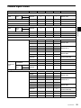
SDI/ アナログマルチ入力アダプター BKM-61D
入力アダプター SDI/ アナログ HD SDI /
アナログコン
シリアルデジタル信号(525/625 コンポーネントおよび
マ ル チ 入 力 ア SDI 入力ア
ポーネント入
NTSC/PAL コンポジット)およびアナログコンポジット信
号 (NTSC/PAL/PAL-M/SECAM) 用のデコーダーを搭載し
ています。入出力端子としては、シリアルデジタル信号用 2
ダプター
ダプター
力アダプター
BKM-61D
BKM-62HS BKM-68X
ご注意
BKM-61D の MONITOR OUT 出力は、本線系出力としての
規格を満足していません。
シ
リ
ア
ル
デ
ジ
タ
ル
入
力
コンポーネント
525/625
コンポジット
NTSC
コンポジット
PAL
コンポジット
NTSC
HD シリアルデジタル信号およびシリアルデジタルコンポー
コンポジット
ネント(525/625)信号用のデコーダーを搭載しています。
HD シリアルデジタル信号は Dual-Link 入力にも対応してい
PAL
ます。入出力端子としては、シリアルデジタル信号用 2
チャンネルを装備しています。
PAL-M
ご注意
YPBPR 525/625
BKM-62HS の MONITOR OUT 出力は、本線系出力として
の規格を満足していません。
GBR 525/625
コンポジット
コンポジット
SECAM
を装備しています。
○
○
○
○
○
○
Y/C PAL-M
○
ア
Y/C SECAM
○
ナ
YPBPR/GBR
ロ
1080/48I
グ
○
YPBPR/GBR
○
1080/50I
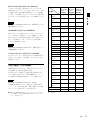
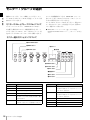
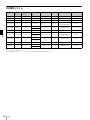
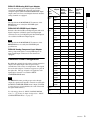
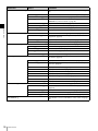
入出力端子パネルの構成
YPBPR/GBR
本機は別売りの入力アダプターを組み合わせることにより、
YPBPR/GBR
入出力端子パネルを自由に構成できます。
各入力アダプターの端子に入力可能な信号は右表のとおり
480/60P
です。各端子に割り付ける入力信号の種類やフォーマット
は、INPUT CONFIGURATION メニューで指定します。
1035/60I
ご注意
YPBPR/GBR
◆ INPUT CONFIGURATION メニューについては、
「[C] 入力チャ
ンネルの設定 − INPUT CONFIGURATION メニュー」(40
ページ)をご覧ください。
○
Y/C PAL
力
フォーマット(AUTO の場合は、最後に受像していた信号
フォーマット)以外では正しく出力されません。
○
○
入
BKM-61D の MONITOR OUT 出力は、INPUT
CONFIGURATION メニューで設定した入力番号の信号
○
Y/C NTSC
アナログコンポーネント入力アダプター BKM-68X
○
○
HD-SDI
HD SDI/SDI 入力アダプター BKM-62HS
アナログコンポーネント信号またはアナログ RGB 信号を入
力することができます。入出力端子としては 1 チャンネル
○
第 1 章 概要
チャンネル、アナログ信号用 3 チャンネルを装備していま
す。
入力信号
○
576/50P
○
YPBPR/GBR
○
YPBPR/GBR
○
1080/60I
○
720/50P
YPBPR/GBR
○
720/60P
デジタル入力端子数
2
2
−
アナログ入力端子数
3
−
1
○:入力可能
特長
11
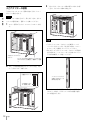
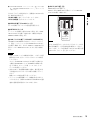
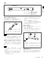
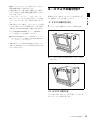
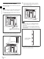
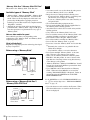
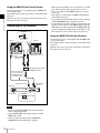
入力アダプターの装着
3
入力アダプターがモニター内部の端子にはまるまで押
し込み、上下のネジを締めて固定する。
入力アダプターは、モニター背面の任意の入力オプション
スロットに装着できます。
第 1 章 概要
ご注意
入力アダプターを組み込んだり、取り出すときは、必ずモ
ニターの主電源を切り、電源コードを抜いてください。
1
モニター背面の入力オプションスロットのカバーを外
す。
ご注意
• 入力オプションスロットのカバーの左側面にシールド
フィンガーが付いています。取り扱いの際は、このシー
ルドフィンガーを損傷しないようにしてください。
• 取りはずした入力オプションスロットのカバーを再度装
着する際には、シールドフィンガーが左側になるように
入力オプションスロット
のカバー
モニターの MAIN POWER スイッチが OFF
になっていることを確認し、電源コードを抜
く。
2
上下方向を確認して、装着してください。
スロット上端の位置合わせマーク(ネジ穴の左)の下
に、入力アダプターを挿入する。
位置合わせマーク
シールドフィンガーが
左側にくるように、本
体に取り付ける。
この位置にアダプ
ターを挿入する。
• シールドフィンガーが損傷したり、間違った側面に付け
られたりした場合、このモニターは VCCI 規格に適合し
ない可能性があります。
12
特長
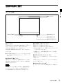
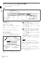
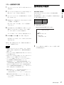
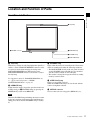
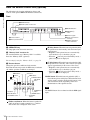
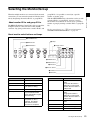
各部の名称と働き
1 タリーランプ
5 OPTION 端子
第 1 章 概要
モニター前面
2 OPERATE ランプ
3 STANDBY ランプ
4 OVER LOAD ランプ
a タリーランプ
出荷時の設定では、PARALLEL REMOTE 端子(背面)の
c STANDBY(スタンバイ)ランプ
本機がスタンバイ状態のとき点灯します。
No.8 ピンと No.9 ピンをショートさせると点灯します。
PARALLEL REMOTE メニューの設定により、
本機がスタンバイ状態になるのは以下の場合です。
• MAIN POWER スイッチ(背面)を ON にしたとき(しば
PARALLEL REMOTE 端子の別のピンをタリー用に使うこ
ともできます。
らく点滅してから点灯します。)
• 外部操作により、本機を動作状態からスタンバイ状態に
切り換えたとき
◆ PARALLEL REMOTE メニューについては、「[D] システムの設
定 − SYSTEM CONFIGURATION メニュー」(45 ページ)を
ご覧ください。
b OPERATE(操作)ランプ
本機がスタンバイ状態のとき(3 STANDBY ランプ参照)
、
BKM-15R の MONITOR I/1 スイッチを押して本機を動作
状態にすると点灯します。
ご注意
STANDBY ランプが点滅している間は、本機を動作状態に
d OVER LOAD(オーバーロード)ランプ
CRT がオーバーロード状態になると、このランプが点灯し
て警告します。
OVER LOAD ランプ点灯時は、コントラストまたは明るさ
を下げてご使用ください。
e OPTION(オプション)端子
オートセットアッププローブ(BKM-14L など)を接続しま
す。
することはできません(内部データの初期化を実行中で
す)。STANDBY ランプが点灯するまでお待ちください。
各部の名称と働き
13
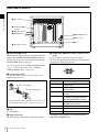
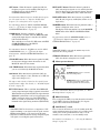
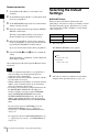
モニター背面
第 1 章 概要
4 入力オプションスロット
5 PARALLEL REMOTE 端子
6 SERVICE 端子
7 NETWORK スイッチ
1 MAIN POWER スイッチ
8 LAN (10/100) 端子
2 AC IN 端子
3 ヒューズ
9 DC 5V OUT 端子
a MAIN POWER(主電源)スイッチ
ON にすると本機は動作状態になります。
SYSTEM CONFIGURATION メニューの設定により、
MAIN POWER スイッチを ON にしたときに本機をスタン
バイ状態にすることもできます。
◆ SYSTEM CONFIGURATION メニューについては、
「[D] システ
ムの設定 − SYSTEM CONFIGURATION メニュー」(45 ペー
ジ)をご覧ください。
d 入力オプションスロット
別売りの入力アダプターを取り付けることができます。
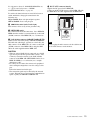
e PARALLEL REMOTE (パラレルリモート)端子(Dsub 9 ピン、凹)
パラレルコントロールスイッチを構成してモニターを外部
操作します。ピン配置と出荷時の各ピンへの機能の割り付
けは以下のとおりです。
5
b AC IN(AC 電源入力)端子(3 ピン)
付属の AC 電源コードで AC 電源を接続します。
9
1
6
AC 電源コード(付属)
AC プラグホルダー(付属)
ピン番号
1
機能
入力信号チャンネル 1 を指定(数値ボタンの機
能)
2
入力信号チャンネル 2 を指定(数値ボタンの機
能)
3
AC プラグホルダーをはめて、プラグが抜けないように固定
する。
4
チャンネルで設定したマーカーの ON/OFF
(MARKER ボタンの機能)
6、7
未設定
このモニターには、必ず付属の電源コードをご使用くださ
8
タリーランプの ON/OFF
い。他の電源コードを使用する場合には、このモニターは
VCCI の規格に適合しない可能性があります。
9
GND
c ヒューズ
T4AH ヒューズを使用します。
14
画面を白黒表示にするか、入力信号に応じて自動
切り換えにするかを選択(MONO ボタンの機能)
5
ご注意
同期信号の選択(SYNC ボタンの機能)
各部の名称と働き
各ピンへの機能の割り付けは、PARALLEL REMOTE メ
ニューで変更できます。
◆ PARALLEL REMOTE メニューについては、「[D] システムの設
定 − SYSTEM CONFIGURATION メニュー」(45 ページ)を
ご覧ください。
BKM-15R 用の DC 電源です。
SMF-700 または BKM-35H に付属のケーブルで BKM-15R
の DC 5V IN 端子と接続します。
第 1 章 概要
以下のようにピンの設定を変えて、各機能の ON/OFF や有
効 / 無効を切り換えます。
ON または有効:各ピンと 9 ピンをショートさせる。
i DC 5V OUT 端子(凹)
OFF または無効:各ピンをオープンにする。
f SERVICE 端子(D-sub 9 ピン、凸)
サービス用端子です。サービス担当者が使用します。
g NETWORK スイッチ
ネットワークに接続する場合は LAN に設定します。BKM15R の LAN (10/100) 端子と直接 1 対 1 で接続する場合は
PEER TO PEER に設定します。
凸コネクター
を差し込む。
h LAN (10/100) 端子(10BASE-T/100BASE-TX)
10BASE-T/100BASE-TX の LAN ケーブル ( シールドタイ
プ、別売り)でネットワークまたは BKM-15R の LAN (10/
100) 端子に接続します。または、SMF-700、BKM-35H に付
属のケーブルで BKM-15R の LAN(10/100)端子に接続し
ます。
ご注意
DC 5V OUT 端子にケーブルをつなぐときは、ケーブル両
端の凸凹を確認し、必ず凸側を本機に接続してください。
つなぐときは、ケーブル先端の形と DC 5V OUT 端子の形
をあわせるようにして、差し込んでください。
ご注意
• 別売りの LAN ケーブルを接続する際は、ノイズによる誤
動作を防ぐため、必ずシールドタイプのケーブルを使用
してください。
モニターを BKM-15R の LAN (10/100) 端子と直接 1 対 1
で接続(NETWORK スイッチを PEER TO PEER に設
定)する際は、ストレート仕様(シールドタイプ)の
ケーブルを使用してください。
• 安全のために、周辺機器を接続する際は、過大電圧を持
つ可能性があるコネクターをこの端子に接続しないでく
ださい。
接続については本書の指示に従ってください。
• ネットワークの使用環境により、接続速度に差が生じる
ことがあります。本機は 10BASE-T/100BASE-TX の通信
速度や通信品質を保証するものではありません。
各部の名称と働き
15
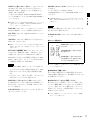
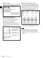
モニターコントロールユニット BKM-15R(別売り)
以下は、モニターコントロールユニット BKM-15R(別売
り)に接続した操作例の解説です。
第 1 章 概要
前面
1 OPERATE ランプ
2“メモリースティック”挿入口
5 DEGAUSS ボタン
6 MONITOR I/1
スイッチ
7 数値ボタン部
3 ファンクションボタン
8 モニター選択ボタンとランプ
4 メニュー操作ボタン
9MANUAL 調整ボタンとつまみ
a OPERATE ランプ
本機が通電中 LED が点灯します。
(H ディレイ)ボタン:ON にすると、画像が水平方向に
移動し、水平同期信号が現われます。
b“メモリースティック”挿入口
スタンダード / デュオサイズ対応のスロットが搭載されて
います。
別売りの“メモリースティック”を挿入します。
• 画像の明るさ(輝度)が自動的に増加して、同期部分の
チェックに便利です。
• H ディレイ時に
表示されます。
ボタンを押すと、パルスクロス画像が
(V ディレイ)ボタン:ON にすると、画像が垂直方向に
◆“メモリースティック”の出し入れについては、「
“メモリース
ティック”の取り扱い」(21 ページ)をご覧ください。
移動し、画面のほぼ中央に垂直同期信号が現われます。
• 画像の明るさ(輝度)が自動的に増加して、同期部分の
c ファンクションボタン
チェックに便利です。
• V ディレイ時に ボタンを押すと、パルスクロス画像が
モニターの動作条件を切り換えます。
押すたびに、ボタン上の LED がついたり(ON)
、消えたり
(OFF)して、モニターの動作条件が切り換わります。
MONO ボタン
APT ボタン
ボタン
COMB ボタン
表示されます。
MONO(白黒)ボタン:ON にすると、画面が白黒になり
ます。OFF にすると、画面はオプションデコーダのカラー
判別結果に応じて自動的にカラーまたは白黒に切り換わり
ます。
CHAR OFF ボタン
ボタン
ボタン
MONO
APT
R OFF
G OFF
COMB
CHAR
OFF
COL
TEMP
COL TEMP
ボタン
ご注意
MONO ボタンは RGB 信号入力時には動作しません。
APT(アパーチャー)ボタン:ON にすると周波数特性を
16 : 9
EXT
SYNC
16:9 ボタン
EXT SYNC ボタン
BLUE ONLY
ボタン
BLUE
ONLY
CHROMA
B OFF MARKER UP
CHROMA
UP ボタン
MARKER ボタン
16
各部の名称と働き
◆ 信号システムごとのアパーチャー補正周波数は「信号システム
別のアパーチャー補正周波数」(20 ページ)をご覧ください。
R/G/B OFF ボタン
(アンダースキャン)ボタン:ON にすると、3% アン
ダースキャンになり、ラスターの四隅までが画面に表示さ
れます。
補正できます。補正量は INPUT CONFIGURATION メ
ニューで設定します。
◆ INPUT CONFIGURATION メニューについては「[C] 入力チャ
ンネルの設定 − INPUT CONFIGURATION メニュー」(40
ページ)をご覧ください。
COMB(くし型フィルター)ボタン:くし型フィルターを
ON/OFF します。SDI/ アナログマルチ入力アダプター
BKM-61D(別売り)を装着しているときに機能します。
(NTSC、PAL、PAL-M 用)
MARKER(マーカー)ボタン:ON にするとマーカーが表
示されます。
マーカーの表示モードの設定は、INPUT
CONFIGURATION メニューの MARKER MODE メニュー
で行います。
ニューで行います。
◆ MARKER MODE メニューについては「[C] 入力チャンネルの
設定 − INPUT CONFIGURATION メニュー」(40 ページ)を
ご覧ください。
◆ YC SEP メニュー、NTSC COMB FILTER メニューについては
「[C] 入力チャンネルの設定 − INPUT CONFIGURATION メ
ニュー」(40 ページ)をご覧ください。
CHAR OFF:ON にすると、いくつかのメニュー上での
ご注意
MANUAL 調整時に、モニターの画面の文字を消します。
EXT SYNC が選択されているときは、マーカーが正しい位
置に表示されない場合があります。
COL TEMP:ON にすると色温度の MANUAL メニューが
表示されます。
CHROMA UP ボタン:ON にするとクロマ値が 12dB アッ
プします。
16:9 ボタン:ON にすると画面のアスペクト比が 16:9 に、
OFF にすると 4:3 になります。
◆ 信号フォーマットにより、アスペクト比が 16:9 に固定されるも
のがあります。詳しくは、
「対応信号システム」(62 ページ)を
ご覧ください。
EXT SYNC(外部同期)ボタン:アナログコンポーネント
入力アダプター BKM-68X(別売り)を装着しているとき
に機能します。ON にすると、BKM-68X の入力信号は、
SYNC 端子に入力されている同期信号に同期します(EXT
SYNC)
。OFF にすると、モニターしている信号に含まれて
いる同期信号に同期します(INT SYNC)。
ご注意
• INT SYNC を選択した場合、コンポーネント信号をモニ
ターするときは、Y 信号に同期信号を付加します。RGB
信号をモニターするときは、G 信号に同期信号を付加し
ます。
• アナログコンポジット信号、Y/C 信号、シリアルデジタ
ル信号をモニターするときは、動作しません。
第 1 章 概要
くし型フィルタの設定は、INPUT CONFIGURATION メ
ニューの YC SEP メニューおよび NTSC COMB FILTER メ
d メニュー操作ボタン
UP
MENU
MENU ボタン:押すとメニューが表
示されます。
DOWN
ENTER
UP/DOWN ボタン:項目および設定
値を選択します。
ENTER ボタン:選択した項目および
設定値を確定します(数値ボタン部の
Ent ボタンも同じ働きをします)。
◆ メニューの操作について詳しくは、
「メニューの操作方法」(28
ページ)をご覧ください。
e DEGAUSS(消磁)ボタン
押すと CRT が消磁されます(本機の電源を入れるたびに、
CRT は自動的に消磁されます)
。再度消磁するときは、5 分
以上間隔をおいてください。
BLUE ONLY(ブルーオンリー)ボタン:ON にすると、
赤と緑の信号がカットされ、青信号のみが白黒画像として
f MONITOR I/1(モニター電源)スイッチ
押すたびにモニターの電源を入 / スタンバイ状態にします。
表示されます。クロマやフェーズの調整、VTR ノイズの
チェックに便利です。
モニターを複数台接続しているときは、モニター選択ボタ
ンにより、指定したモニターの電源だけを入 / スタンバイ
R/G/B OFF ボタン:ON にすると、R(赤)
、G(緑)
、B
状態にしたり、全モニターの電源を同時に入 / スタンバイ
状態にすることができます。
(青)のビームをカットします。
◆ モニター選択ボタンについては、「モニター / グループの選択」
(26 ページ)をご覧ください。
各部の名称と働き
17
g 数値ボタン部
i MANUAL(手動)調整ボタンとつまみ
モニターしたい入力信号のチャンネル番号を指定したり、
メニューで設定値を入力するときに使います。
ボタンを押すたびに、ボタン上の LED(緑)がついたり
(ON)、消えたり (OFF) します。ON にすると、画面のコン
トラスト、明るさ(黒レベル)、クロマ(色の飽和度)
、
INPUT
第 1 章 概要
1
3
2
Del
4
5
6
0
7
8
9
Ent
Del ボタン:入力した数値や
文字を消去します。
フェーズ(色相)を、それぞれつまみで調整できます。ま
た、PHASE つまみは、メニューで設定値を入力するときに
数値ボタン
も使います。
各調整項目は、PICTURE ADJ メニューでプリセット値を
設定しておくことができます。
Ent ボタン:入力した数値や
文字を確定します(メニュー
操作ボタンの ENTER ボタン
も同じ働きをします)
。
PHASE
(フェーズ)
調整ボタン
とつまみ
CHROMA
(クロマ)調
整ボタンと
つまみ
CONTRAST
BRIGHT
(明るさ) (コントラス
調整ボタン ト)調整ボタ
ンとつまみ
とつまみ
チャンネル番号入力について
チャンネル番号 1 ∼ 9 を入力する場合は、その数字を入力
します。
10 ∼ 99 の 2 桁のチャンネル番号を入力する場合は、まず、
0 を入力し、次に 2 桁の数字を入力します。
PHASE
CHROMA
BRIGHT
CONTRAST
MANUAL
MANUAL
MANUAL
MANUAL
h モニター選択ボタンとランプ
複数のモニターをネットワーク接続しているときに、モニ
ター ID No.、グループ ID No. または ALL を指定してリ
モート接続をするとき使います。
◆ PICTURE ADJ メニューについては、「[A] 画像の調整 −
PICTURE ADJ メニュー」(34 ページ)をご覧ください。
SINGLE
表示窓:選択された ID
No.、または ALL が表示さ
れます。接続処理中は点滅
します。
GROUP
SINGLE ボタン:シングル
接続モードを選択します。
• SECAM、PAL、PAL-M、アナログコンポーネントまた
は SDI(コンポーネントシリアルデジタルまたはコンポ
REMOTE
ALL
SINGLE
GROUP
ALL
GROUP ボタン:グループ
接続モードを選択します。
ご注意
ジット PAL)フォーマットでは、フェーズを調整できま
せん。
• RGB 信号ではフェーズおよびクロマを調整できません。
ALL ボタン:オール接続
モードを選択します。
ランプ:押したボタンのランプ
が、設定中は点滅し、確定する
と点灯します。
18
各部の名称と働き
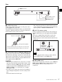
背面
1 AC IN 端子
第 1 章 概要
2 LAN (10/100) 端子
3 DC 5V IN 端子
4 NETWORK スイッチ
a AC IN(AC 電源入力)端子(3 ピン)
付属の AC 電源コードで AC 電源を接続します。
AC 電源を使用する場合、AC IN 端子が優先しますので、
DC 5V IN 端子にケーブルを接続する必要はありません。
AC 電源コード(付属)
• 安全のために、周辺機器を接続する際は、過大電圧を持
つ可能性があるコネクターをこの端子に接続しないでく
ださい。
接続については本書の指示に従ってください。
• ネットワークの使用環境により、接続速度に差が生じる
ことがあります。本機は 10BASE-T/100BASE-TX の通信
速度や通信品質を保証するものではありません。
c DC 5V IN 端子(凸)
SMF-700 または BKM-35H に付属のケーブルでモニターの
DC 5V OUT 端子と接続します。
この場合、本機の電源は DC 5V ケーブルを通じてモニター
AC プラグホルダー(付属)
AC プラグホルダーをはめて、プラグが抜けないように固定
する。
から供給されるため、AC 電源を接続する必要はありませ
ん。
また、AC 電源が接続されているときは、働きません。
ご注意
このコントローラーには、必ず付属の電源コードをご使用
ください。他の電源コードを使用する場合には、このコン
トローラーは VCCI の規格に適合しない可能性があります。
b LAN (10/100) 端子(10BASE-T/100BASE-TX)
10BASE-T/100BASE-TX の LAN ケーブル ( シールドタイ
プ、別売り)でネットワークまたはモニターの LAN (10/
100) 端子に接続します。または、SMF-700、BKM-35H に付
属のケーブルでモニターの LAN (10/100) 端子に接続しま
す。
ご注意
凹コネクターを
差し込む。
ご注意
DC 5V IN 端子にケーブルをつなぐときは、ケーブル両端
の凸凹を確認し、必ず凹側を BKM-15R に接続してくださ
い。
つなぐときは、ケーブル先端の形と DC 5V IN 端子の形を
あわせるようにして、差し込んでください。
• 別売りの LAN ケーブルを接続する際は、ノイズによる誤
動作を防ぐため、必ずシールドタイプのケーブルを使用
してください。
BKM-15R をモニターの LAN (10/100) 端子と直接 1 対 1
で接続(NETWORK スイッチを PEER TO PEER に設
定)する際は、ストレート仕様(シールドタイプ)の
d NETWORK スイッチ
LAN (10/100) 端子にネットワーク接続する場合は LAN に
設定します。モニターの LAN (10/100) 端子と直接 1 対 1 で
BKM-15R を接続する場合は PEER TO PEER に設定しま
す。
ケーブルを使用してください。
各部の名称と働き
19
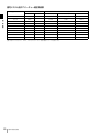
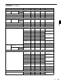
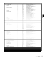
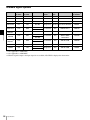
信号システム別のアパーチャー補正周波数
信号システム
シリアルデジタル入力
アナログ入力
コンポジット (Y/C)
コンポーネント (YPBPR)
GBR
575/50I
5 MHz
5 MHz
5 MHz
5 MHz
480/60I
5 MHz
5 MHz
5 MHz
5 MHz
SDI
HD SDI
第 1 章 概要
1080/48I
25 MHz
25 MHz
25 MHz
1080/50I
25 MHz
25 MHz
25 MHz
25 MHz
25 MHz
576/50P
480/60P
1035/60I
25 MHz
25 MHz
25 MHz
1080/60I
25 MHz
25 MHz
25 MHz
720/50P
25 MHz
25 MHz
25 MHz
720/60P
25 MHz
25 MHz
25 MHz
空欄:信号が入力できないか、または、入力できてもアパーチャー補正が動作しないことを意味します。
20
25 MHz
25 MHz
各部の名称と働き
“メモリースティック”の取り扱い
本機には、スタンダード / デュオサイズ対応スロットが搭
載されています。このスロット搭載の機器では、“メモリー
スティック”のサイズを自動的に判断する機構により、“メ
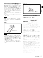
取り出しかた
1 アクセスランプが点滅していないこ
とを確認する。
デュオ”/“メモリースティック PRO デュオ”のどちらで
もご使用いただけます。
2“メモリースティック”を押す。
“メモリースティック”が出てきます。
別売りの“メモリースティック”は、以下の方法で出し入
れします。
◆“メモリースティック”のデータ操作については、各メニューで
説明してあります。
ご注意
“メモリースティック”が動作しているとき(データのセー
“メモリースティック”について
“メモリースティック”とは?
ブ・ロード中)は、“メモリースティック”を取り出さない
でください。
“メモリースティック”
、“メモリースティック PRO”、
“メ
モリースティックデュオ”、 、
および
入れかた
は、ソニー株式会社の商標です。
“メモリースティック”は、小さくて軽く、しかもフロッ
“メモリースティック”挿入口
第 1 章 概要
モリースティックデュオ”アダプターなしで、標準サイズ
の“メモリースティック”、小型の“メモリースティック
ピーディスクより大容量の IC 記録メディアです。“メモ
リースティック”対応機器間でデータをやり取りするのに
お使いいただけるだけでなく、着脱可能な外部記録メディ
アの1つとしてデータの保存にもお使いいただけます。
“メモリースティック”には、標準サイズのものとその小型
サイズの“メモリースティックデュオ”があります。
矢印の面を上にする。
“メモリースティック”の種類
“メモリースティック”には、用途に応じて以下の 6 種類が
あります。
ご注意
• “メモリースティックデュオ”/“メモリースティック
PRO デュオ”を本機で使うときは、メモリースティック
デュオアダプターをつけずにそのまま挿入してください。
“メモリースティック”
著作権保護技術(マジックゲート)が必要なデータ以外の、
あらゆるデータを記録できる“メモリースティック”です。
• 逆向きに無理に入れると、“メモリースティック”挿入口
が破損することがあります。
“メモリースティック”(マジックゲート/高速データ転送
対応)
• “メモリースティック”挿入口には“メモリースティッ
ク”以外のものを入れないでください。故障の原因とな
著作権保護技術(マジックゲート)を搭載し、高速データ
転送に対応した“メモリースティック”です。
ります。
“メモリースティック”対応商品、「マジックゲート“メモ
リースティック”」対応商品、および「“メモリースティッ
ク”PRO」対応商品でご使用いただけます。1)
1) すべての対応商品における動作を保証するものではありません。(一部使
用できない対応商品があります。)
本機は、この“メモリースティック”の高速データ転送に
は対応していません。
マジックゲート“メモリースティック”
著作権保護技術(マジックゲート)を搭載した“メモリー
スティック”です。
本機ではご使用いただけません。
各部の名称と働き
21
“メモリースティック− ROM”
“メモリースティック”について
あらかじめデータが記録されている、読み出し専用の“メ
モリースティック”です。データの記録や消去はできませ
ん。
端子
第 1 章 概要
“メモリースティック”
(メモリーセレクト機能付き)
内部に複数のメモリー(128MB)を搭載している“メモ
リースティック”です。
本体裏面のメモリーセレクトスイッチにより、用途に応じ
誤消去防止つまみ
てご使用になるメモリーを選択できます。各メモリーを同
時に、また連続でご使用になることはできません。
ラベル貼り付け部
裏
表
“メモリースティック PRO”
“メモリースティック PRO”対応商品でのみお使いいただ
ける、著作権保護技術(マジックゲート)を搭載した“メ
モリースティック”です。
“メモリースティックデュオ”/“メモリース
ティック PRO デュオ”について
“メモリースティックデュオ”/“メモリースティック PRO
デュオ”
デュオサイズの“メモリースティック”です。
使用可能な“メモリースティック”
端子
誤消去防止つまみ
動かすときは、先
の細いものを使用
する。
• 本機では、“メモリースティック”
、“メモリースティック
PRO”、
“メモリースティックデュオ”、
“メモリース
ティック PRO デュオ”がご使用いただけます。ただし、
本機はマジックゲート規格に対応していないため、本機
で表示するデータはマジックゲートによる著作権の保護
の対象にはなりません。
• 本機では、4GB までの“メモリースティック”で動作を
確認しています。ただし、すべての“メモリースティッ
ク”での動作を保証するものではありません。
データの読み込み / 書き込みスピードについて
お使いの“メモリースティック”と機器の組み合わせに
よっては、データの読み込み / 書き込み速度が異なります。
マジックゲートとは?
マジックゲートは、ソニーが開発した、著作権を保護する
技術の総称です。
裏
表
ご注意
• 誤消去防止つまみを「LOCK」にすると記録や編集、消
去ができなくなります。
• 以下の場合、データが破損されることがあります。
− 読み込み中、書き込み中に“メモリースティック”を
取り出したり、本機の電源を切った場合
− 静電気や電気的ノイズの影響を受ける場所で使用した
場合
• 大切なデータは、バックアップを取っておくことをおす
すめします。
• ラベル貼り付け部には、専用ラベル以外は貼らないでく
ださい。
• ラベルを貼るときは所定のラベル貼り付け部に貼ってく
ださい。はみ出さないようにご注意ください。
• 持ち運びや保管の際は、付属の収納ケースに入れてくだ
さい。
• 端子部には手や金属などで触れないでください。
• 強い衝撃を与えたり、曲げたり、落としたりしないでく
ださい。
• 分解したり、改造したりしないでください。
• 水にぬらさないでください。
• 以下のような場所でのご使用や保管は避けてください。
− 高温になった車の中や炎天下など気温の高い場所
− 直射日光のあたる場所
− 湿気の多い場所や腐食性のある場所
22
各部の名称と働き
• 複数の“メモリースティック”を挿入しないでください。
機器の破損の原因となる場合があります。
• ご使用の際は、正しい挿入方向をご確認のうえご使用く
ださい。間違ったご使用は機器の破損の原因となります
PRO デュオ”は、小さいお子様の手の届くところに置か
ないようにしてください。誤って飲み込む恐れがありま
す。
• 本機で扱えるファイル数は、" メモリースティック "1 枚あ
たり 1000 個までです。1000 個を超えるファイルを作成し
た場合は「TOO MANY FILES」の警告が表示されます
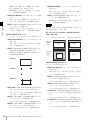
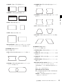
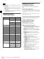
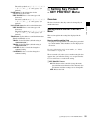
画面のアスペクト比を 16:9 から 4:3 に切り換えたとき
は、付属の 4:3 マスクに交換してください。
4:3 マスクの取り付けかた
1
16:9 マスクの上側をはずしてから、下側を引き抜く。
2
4:3 マスク(付属)の下側をはめ込んでから、上側を
第 1 章 概要
のでご注意ください。
• “メモリースティックデュオ”/“メモリースティック
4:3 マスクの取り付け
ので、FILE MENAGEMENT メニュー、DELETE メ
ニューで不要なファイルを削除してください。
◆ FILE MANAGEMENT メニュー、DELETE メニューについ
ては「[F] システムデータの操作− FILE MANAGEMENT メ
ニュー」(54 ページ)をご覧ください。
• 本機で扱えるファイル名称の文字数は 20 文字までです。
名称が 20 文字を超えるファイルは本機では表示されませ
んのでご注意ください。
押し込む。
16:9 マスクに戻すには
「4:3 マスクの取り付けかた」と同じ手順で 4:3 マスクを
はずし、16:9 マスクを取り付けます。
4:3 マスクの取り付け
23
を通じてモニターから供給されるため、AC 電源を接続す
接続
る必要はありません。
BKM-15R を AC 電源で使用する場合
BKM-15R に付属の AC 電源コードを AC IN 端子に接続し
ます。
第 1 章 概要
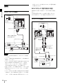
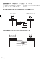
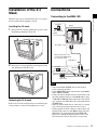
BKM-15R との接続
AC 電源を使用する場合、AC IN 端子が優先しますので、
DC 5V IN 端子にケーブルを接続する必要はありません。
NETWORK
LAN
モニター
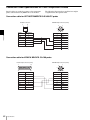
ネットワーク接続
PEER TO PEER
PEER TO PEER
にする。
NETWORK
LAN
PEER TO PEER
DC 5V OUT 端子
LAN (10/100) 端子
本機を AC 電源で使用す
るときは接続しない。
NETWORK
PEER TO PEER
PEER TO PEER にする。
DC 5V IN 端子
LAN にする。
DC 5V OUT
端子
LAN (10/
100) 端子
SMF-700 など
LAN
モニター
LAN (10/100)
端子
LAN
(10/100)
端子
BKM-15R
AC IN 端子
モニター
スイッチングハブ
(AUTO MDI/
MDI-X 機能付き)
本機を AC 電源で
使用するときは
接続しない。
ご注意
• モニターの MAIN POWER スイッチをオフにして接続し
てください。
• モニターとBKM-15RのNETWORKスイッチをPEER TO
PEER にしてください。
• モニターの LAN (10/100) 端子と BKM-15R の LAN (10/100)
端子を 10BASE-T/100BASE-TX のストレート仕様の
LAN ケーブル(シールドタイプ、別売り)
、SMF-700、
または BKM-35H に付属のケーブルで接続します。
• 別売りの LAN ケーブルを接続する際は、ノイズによる誤
動作を防ぐため、必ずシールドタイプのケーブルを使用
してください。
• モニターの DC 5V OUT 端子と BKM-15R の DC 5V IN 端子
を SMF-700、または BKM-35H に付属のケーブルで接続
します。この場合、BKM-15R の電源は DC 5V ケーブル
24
接続
BKM-15R
AC IN 端子
DC 5V IN 端子
NETWORK
LAN
PEER TO PEER
LAN にする。
LAN (10/100)
端子
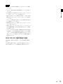
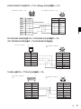
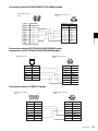
ご注意
• モニターの MAIN POWER スイッチをオフにして接続し
てください。
• モニターと BKM-15R の NETWORK スイッチを LAN にし
第 1 章 概要
てください。
• 10BASE-T/100BASE-TX の LAN ケーブル(シールドタイ
プ、別売り)でネットワークに接続します。
• 別売りの LAN ケーブルを接続する際は、ノイズによる誤
動作を防ぐため、必ずシールドタイプのケーブルを使用
してください。
• モニターと BKM-15R を合わせて 32 台(BKM-15R は最大 4
台)接続することができます。
• BKM-15R はサブネットを越えてモニターをコントロール
することはできません。
• 別売りのスイッチングハブは、ストレート / クロスケーブ
ルの自動選択機能(AUTO MDI/MDI-X)をもった機器
をご使用ください。
• モニターの DC 5V OUT 端子と BKM-15R の DC 5V IN 端子
を SMF-700、または BKM-35H に付属のケーブルで接続
します。この場合、BKM-15R の電源は DC 5V ケーブルを
通じてモニターから供給されるため、AC 電源を接続する
必要はありません。
BKM-15R を AC 電源で使用する場合
BKM-15R に付属の AC 電源コードを AC IN 端子に接続し
ます。
AC 電源を使用する場合、AC IN 端子が優先しますので、
DC 5V IN 端子にケーブルを接続する必要はありません。
接続
25
モニター / グループの選択
第 1 章 概要
複数のモニターをネットワーク接続しているときに、モニ
モニターを複数接続するときは、NETWORK メニューで、
ター ID No. またはグループ ID No. を指定して、リモート接
続をすることができます。
各モニターに対して ID No. およびグループ No. として 1 ∼
99 までの番号を付けることができます。
モニター ID No. とグループ ID No. について
モニター ID No. やグループ ID No. を入力して、特定のモニ
ターまたはモニターグループを指定するときは、前面のモ
ニター選択ボタンを使います。
モニターコントロールユニット BKM-15R は、LAN (10/
100) 端子に接続されたモニターを複数台操作できます。こ
のとき、各モニター ID No.、グループ ID No. によって、特
定のモニターまたはモニターグループだけを操作できます。
◆ NETWORK メニューについては、「[D] システムの設定 −
SYSTEM CONFIGURATION メニュー」(45 ページ)をご覧く
ださい。
モニター選択ボタンとランプについて
1 UP/DOWN ボタン
2 MENU ボタン
4 ランプ
3 ENTER ボタン
5 表示窓
REMOTE
UP
MENU
PHASE
CHROMA
BRIGHT
CONTRAST
INPUT
SINGLE
1
2
3
Del
4
5
6
0
7
8
9
Ent
GROUP
DOWN
ENTER
MANUAL
MANUAL
MANUAL
MANUAL
ALL
SINGLE
GROUP
ALL
6 SINGLE ボタン
7 GROUP ボタン
8 ALL ボタン
9 数値ボタン
q; Ent ボタン
qa Del ボタン
ピン番号
機能
ピン番号
1 UP ボタン
ID No. を上げる。
6 SINGLE ボタン シングル接続モードを選択する。
1 DOWN ボタン
ID No. を下げる。
2 MENU ボタン
設定中に押すと設定前の状態に戻る。
3 ENTER ボタン 表示部の値を確定する。
4 ランプ
押し続けると接続されている全てのモニターにモ
ニター ID No. を表示する。
7 GROUP ボタン グループ接続モードを選択する。
押し続けると接続されている全てのモニターにグ
SINGLE/GROUP/ALL ボタンのうち、押したボ
ループ ID No. を表示する。
タンのランプが、ID No. を設定中は点滅し、確定
5 表示窓
26
機能
すると点灯する。
8 ALL ボタン
オール接続モードを選択する。
選択されたモニター ID No.、グループ ID No.、ま
9 数値ボタン
ID No. を入力する。
たは ALL が表示される。接続処理中は点滅する。
0 Ent ボタン
表示部の値を確定する。
qa Del ボタン
ID No. を消去する。
モニター / グループの選択
リモート接続操作の手順
1
3
4
モニター 1 台ごとに異なるモニター ID No. を設定し、必
要に応じて、グループ ID No. を設定する。
モニターとコントローラーの NETWORK スイッチ ( 背
面)を LAN にする。
SINGLE ボタン、GROUP ボタンまたは ALL ボタンを押
して接続モードを選択する。
押したボタンのランプが点滅し、モニターを認識する
と点灯します。
5
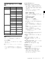
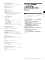
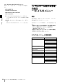
基本設定の選択
BVM-A20F1M のみ
初めてお使いになるときは、お使いになる地域の選択を
行ってください。
地域を選択すると、CH1 ∼ 30 の色温度が、各地域に指定さ
れた値に初期設定されます。
色温度
JAPAN
D93
OTHER AREA
D65
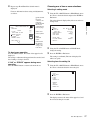
1
本機の電源を入れる。
SELECT SETTING 画面が表示されます。
UP/DOWN ボタンまたは数値ボタンを押してシングル
接続モードのときはモニター ID No.、グループ接続
モードのときはグループ ID No. を選択する。
6
第 1 章 概要
2
モニターとコントローラー1 台ごとに異なる IP アドレス
を設定する。
SELECT SETTING
モニター ID No.、グループ ID No. の最大値は 99 です。
JAPAN
COLOR TEMP: D93
ENTER3 または Entq; ボタンを押して決定する。
OTHER AREA
COLOR TEMP: D65
表示部にモニター ID No.、グループ ID No. または ALL
が表示されます。
操作 1 ∼ 3 を1度設定したあとは、手順 4 ∼ 6 の操作によ
り、リモート接続を行います。
ご注意
• 割り付けられていないモニター ID No.、グループ ID No.
2
メニュー操作ボタンを使用して(28 ページ参照)
、使用
する地域を設定する。
を選択した場合、設定は変わらず、選択前の接続状態を
維持します。
• 同じモニター ID No. が複数ある場合は IP アドレスが小さ
い方が選択されます。
• 異なるモニター ID No. を設定しても、同一の IP アドレス
を設定していると、接続することができません。
• ネットワーク接続によるリモートコントロールを行うに
は、SYSTEM CONFIGURATION メニューの
NETWORK メニュー、NETWORK SETTINGS メニュー
で MONITOR ID、GROUP ID や IP アドレスが正しく設
定されている必要があります。また、CONTROLLER メ
ニューの NETWORK SETTINGS メニューで IP アドレス
が正しく設定されている必要があります。
◆ NETWORK メニュー、NETWORK SETTINGS メニューに
ついては、「[D] システムの設定 − SYSTEM
CONFIGURATION メニュー」(45 ページ)をご覧ください。
◆ NETWORK SETTINGS メニューについては、「[H] コント
ローラーの設定 − CONTROLLER メニュー」(58 ページ)
をご覧ください。
基本設定の選択
27
2
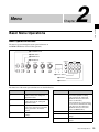
メニュー
第
章
第 2 章 メニュー
メニューの操作方法
メニュー操作ボタン
メニューは、モニターコントロールユニット BKM-15R(別
売り)のボタンを使って操作します。
1 UP/DOWN ボタン
2 MENU ボタン
3 ENTER ボタン
4 PHASE つまみ
REMOTE
UP
MENU
PHASE
CHROMA
BRIGHT
CONTRAST
INPUT
SINGLE
1
2
3
Del
4
5
6
0
7
8
9
Ent
GROUP
DOWN
ENTER
MANUAL
MANUAL
MANUAL
MANUAL
ALL
SINGLE
GROUP
ALL
5 数値ボタン
6 Ent ボタン
7 Del ボタン
下記に、メニュー操作ボタンの働きを示します。
ボタン
機能
ボタン
1 UP ボタン
カーソルを上に動かす。設定モードでは、
4 PHASE つまみ
1 DOWN ボタン
2 MENU ボタン
3 ENTER ボタン
28
メニューの操作方法
機能
時計方向に回すと、カーソルを上に動か
調整・設定値を上げる。
す。設定モードでは、調整・設定値を上げ
カーソルを下に動かす。設定モードでは、
る(UP ボタンと同機能)。
調整・設定値を下げる。
反時計方向に回すと、カーソルを下に動か
メニュー画面を表示する。1 つ前の階層の
す。設定モードでは、調整・設定値を下げ
メニュー画面に戻る(メインメニュー画面
る(DOWN ボタンと同機能)。
では、通常画面に戻る)。
5 数値ボタン
数値を入力する。
選択した項目・設定を確定する。
6 Ent ボタン
選択した項目・設定を確定する。
7 Del ボタン
入力した数値や文字を消去する。
メニューを表示させるには
メニューの操作手順
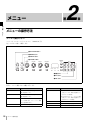
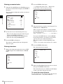
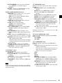
MENU ボタンを押すと、メインメニューが表示されます。
次の手順でメニューを表示し、設定や調整を行います。
1
M EN U
PICTURE ADJ .. .
COLOR TEMP AD J. ..
INPUT CONFI GU RA TI ON .. .
SYSTEM CONF IG UR AT IO N. ..
INSTALLATIO N SE TT IN GS .. .
FILE MANAGE ME NT .. .
STATUS...
CONTROLLER. ..
メインメニューが表示されます。
2
UP または DOWN ボタンを押すか、PHASE つまみを回
して、調整や設定を行いたいメニュー項目にカーソル
を合わせる(例:DOWN ボタンを押して INPUT
CONFIGURATION... に合わせる)。
OF F
MENU
ここで表示されているメニューを選ぶと、それぞれのメ
ご注意
PICTURE ADJ...
COLOR TEMP ADJ...
INPUT CONFIGURATION...
SYSTEM CONFIGURATION...
INSTALLATION SETTINGS...
FILE MANAGEMENT...
STATUS...
CONTROLLER...
青い文字で表示されるメニュー項目については、設定でき
KEY PROTECT
ニューの第 1 階層が表示されます。
◆ メニュー選択層のメニューの内容については「メニューの階層
構造」(32 ページ)をご覧ください。
OFF
カーソル
ません。
メニュー番号について
本書では、説明の必要なメニューにそれぞれの分類と階層
を示すメニュー番号を付けています。メニュー番号は、メ
ニューの分類(メインメニューに表示されるメニュー)を
示すアルファベットと、それぞれの階層を示す数字で構成
されています。この番号は画面には表示されません。
例:[A221]
PICTURE ADJ メニューの下であることを示す。
第 1 階層の 2 番目のメニューであることを示す。
第 2 階層の 2 番目のメニューであることを示す。
A221
第 2 章 メニュー
KEY PROTECT
MENU ボタンを押す。
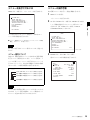
3
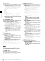
ENTER ボタンまたは Ent ボタンを押す。
選んだメニューの第 1 階層が表示されます。
INPUT CONFIGURATION
CH01
FORMAT...
SDI HD/D1 AUTO
SLOT NO
OPTION1
INPUT NO
DIGITAL1
SCREEN ASPECT
16:9
SCAN SIZE
NORMAL
SYNC MODE
--COLOR TEMP
PICTURE PRESET
MATRIX...
D93
PRESET1
第 3 階層の 1 番目のメニューであることを示す。
ご注意
メニュー番号は説明が必要なメニューにだけ付いています。
そのため、メニュー番号の連番は、メニュー階層のすべて
のメニューを含めて数えたものではありません。
メニューの操作方法
29
4
手順 2 と 3 を繰り返して、設定または調整したい階層の
3
メニューを表示し、設定を行う。
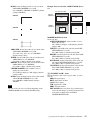
ENTER (Ent) ボタンを押す。
設定が確定されます(白文字に戻る)。
設定の方法については、次ページをご覧ください。
第 2 章 メニュー
INPUT CON F IG UR AT IO N
C H01
APERTURE
VALUE
YC SEP
NTSC COMB FILT ER
MARKER DISPLAY
MODE...
H PHASE
CHANNEL NAME...
OF F
0 00
-- -- OF F
00 0
「r」は次ページ
が、「R」は前
ページがある
ことを示す。
設定リストから選択する
1
UP/DOWN ボタンを押すか、または PHASE つまみを回
して設定リストの選択したい項目にカーソルを合わせ
る。
複数の選択肢か
ら選ぶ。
PARALLEL REMOTE(2/2)
1 PIN
BLUE ONLY
R OFF
G OFF
B OFF
CHROMA UP
数値を入力
する。
COPY FROM...
さらに1つ下の
階層のメニュー
に進める。
MARKER
TALLY
DEGAUSS
POWER OFF
メニュー操作を中断したいときは
MENU ボタンを押します。1 つ前の階層が表示されます。
実行中の設定や調整は元の状態に戻り、データの読み出し・
書き込みなどは強制終了します。
2
メニュー操作中に“NG”または“ERROR”の表示
が出たときは
選んだ設定が確定され、上の階層のメニューに戻りま
す。
MENU ボタンを押すと、操作中のメニュー画面に戻りま
す。
数値を入力する
複数の設定内容から 1 つを選択する
1
設定モードにして、選択する
1
ENTER (Ent) ボタンを押す。
UP/DOWN ボタンを押すか、または PHASE つまみを回
して設定したい項目にカーソルを合わせ、ENTER
(Ent) ボタンを押す。
UP/DOWN ボタンを押すか、または PHASE つまみを回
して設定したい項目にカーソルを合わせ、ENTER
選んだ項目が黄色文字に変わり、設定モードになりま
す。
(Ent) ボタンを押す。
MARKER MODE(1/3)
CH01
ASPECT MODE
16:9
ASPECT
--H POSITION
000
MARKER BRIGHT
90IRE
選んだ項目が黄色文字に変わり、設定モードになりま
す。
INPUT CO NF IG UR AT IO N
CH01
FORMAT...
S DI H D/ D1 A UT O
SLOT NO
O PT IO N1
INPUT NO
DI GI TA L1
SCREEN ASPE CT
1 6: 9
SCAN SIZE
N OR MA L
SYNC MODE
- -COLOR TEMP
PICTURE PRE SE T
MATRIX...
2
30
D9 3
PR ES ET 1
ASPECT MARKER
LINE
COLOR
ASPECT BLANKING
MODE
2
OFF
----OFF
---
次のいずれかの方法で数値を設定する。
• 数字キーで数値を直接入力し、ENTER (Ent) ボタン
を押す。
UP/DOWN ボタンを押すか、または PHASE つまみを回
して設定を切り換える。
メニューの操作方法
• UP/DOWN ボタンを押して数値を選ぶ。
• PHASE つまみを回して数値を選ぶ。
3
ENTER (Ent) ボタンを押す。
4
設定した数値が確定されます(白文字に戻る)。
ENTER (Ent) ボタンを押す。
選んだ文字が入力されます。
文字を入力する
1
CHANNEL NAME
CH01
PROG
EDIT
CAM
VTR
PREV
設定画面を表示し、UP/DOWN ボタンを押すか、また
は PHASE つまみを回してカーソルを NEW NAME に
合わせる。
CH AN NE L NA ME
CH01
PROG
EDIT
CAM
VTR
PREV
C?
5
NEW NAME
手順 3 と 4 を繰り返して残りの文字を入力したら、
ENTER (Ent) ボタンを押す。
第 2 章 メニュー
NEW NAME
設定した文字が確定され、1 つ上の階層のメニューに戻
ります。
2
入力した文字を修正するには
ENTER (Ent) ボタンを押す。
文字入力位置を示す「?」(黄色文字)が現れ、文字入
数値ボタンの Del ボタンを押すと、
[?](黄色文字)の左隣
の文字が削除されます。
力モードになります。
CH AN NE L NA ME
CH01
PROG
EDIT
CAM
VTR
PREV
NEW NAME
?
3
UP/DOWN ボタンを押すか、PHASE つまみを回して、
入力したい文字を選びます。
UP ボタンを押すか、PHASE つまみを時計方向に回す
と、以下の順で文字および記号が現れます。
A B……Y Z 0 1……8 9 ( , ) : ; .− + / & (スペース) ?
DOWN ボタンを押すか、PHASE つまみを反時計方向
に回すと、逆の順に現れます。
使用できる記号はメニューの種類により異なります。
「
(スペース)
」は 1 文字目には使用できません。
メニューの操作方法
31
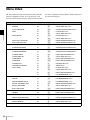
メニューの階層構造
メニュー構成
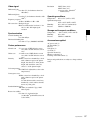
ここでは、メニュー選択層と第 1 階層の構造を示します。
各メニューの詳細は、この後の各メニューの説明をご覧く
ださい。
第 2 章 メニュー
メインメニュー
第1層
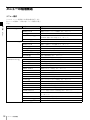
PICTURE ADJ [A]
内容
画像調整メニューです。
(34 ページ)
PRESET VALUE
調整するプリセットデータを選択します。(34 ページ)
AUTO [A1]
クロマ / フェーズ / マトリクスを自動調整で設定します。(35 ページ)
MANUAL ADJUST[A2]
フェーズ / クロマ / ブライトネス / コントラストのプリセットデータを
MANUAL 調整つまみで設定します。(35 ページ)
COPY FROM [A3]
COLOR TEMP ADJ [B]
PRESET VALUE
調整する色温度データを選択します。
(37 ページ)
MANUAL [B1]
色温度を MANUAL つまみで設定します。(37 ページ)
AUTO [B2]
色温度を自動調整で設定します。
(38 ページ)
COPY FROM [B3]
他の色温度データをコピーします。
(39 ページ)
RESTORE FACTORY DATA [B4]
色温度データを工場出荷時の設定値に戻します。
(39 ページ)
ANALYZE [B5]
色度、輝度を測定します。(39 ページ)
CHxx
現在選択しているチャンネルが表示されます。(41 ページ)
FORMAT [C1]
信号の種類を選択します。(42 ページ)
SLOT NO
スロット番号を選択します。(41 ページ)
INPUT NO
入力端子番号を選択します。(41 ページ)
SCREEN ASPECT
画面のアスペクトを設定します。
(41 ページ)
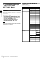
SCAN SIZE
スキャンサイズを設定します。(41 ページ)
SYNC MODE
同期信号を設定します。(41 ページ)
INPUT
CONFIGURATION [C]
他の画像調整プリセットデータをコピーします。
(36 ページ)
色温度を調整するためのメニューです。(36 ページ)
入力信号に関する各種データを設定するメニューです。(40 ページ)
COLOR TEMP
色温度を選択します。
(41 ページ)
PICTURE PRESET
画像調整プリセットを選択します。
(42 ページ)
MATRIX [C2]
信号システムのマトリクスを設定します。(43 ページ)
APERTURE
アパーチャー補正をするかどうかを設定します。
(42 ページ)
VALUE
アパーチャー補正量を入力します。
(42 ページ)
YC SEP
Y/C 分離フィルターを選択します。(42 ページ)
NTSC COMB FILTER
NTSC COMB フィルタの種類を設定します。(42 ページ)
MARKER DISPLAY
マーカーを表示するかどうかを設定します。(42 ページ)
MODE [C3]
マーカーのアスペクトやセーフエリア、セーフタイトルなどを設定しま
す。(43 ページ)
32
メニューの階層構造
H PHASE
画面の水平方向の位置を調整します。(42 ページ)
CHANNEL NAME [C4]
チャンネル名を付けます。(45 ページ)
COPY FROM [C5]
他のチャンネルデータをコピーします。(45 ページ)
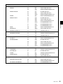
メインメニュー
第1層
内容
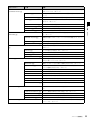
SYSTEM
リモートコントロール機能やネットワークなどシステムに関する設定を
CONFIGURATION [D]
するメニューです。
(45 ページ)
NETWORK [D1]
ネットワークによるリモートコントロール機能の設定をします。
(46
ページ)
PARALLEL REMOTE [D2]
パラレルリモートコントロール機能の設定をします。
(47 ページ)
POWER [D3]
主電源や MONITOR I/1 スイッチを入れたときのモニターの状態を設
定します。
(48 ページ)
BLANKING SETTINGS [D4]
ブランキング関連の設定をします。
(48 ページ)
画面に表示させる情報を設定します。
(48 ページ)
PASSWORD [D6]
パスワードの変更や割付を設定します。
(48 ページ)
MAINTENANCE [D7]
メインテナンス用のメニューを表示します。(49 ページ)
INSTALLATION
ランディング、画像のゆがみなどの設置調整をするためのメニューで
SETTINGS [E]
す。(49 ページ)
LANDING ADJUST [E1]
第 2 章 メニュー
ON SCREEN SET [D5]
地磁気の影響によるビームランディングのずれを調整します。
(50 ペー
ジ)
ALIGNMENT [E2]
画像の位置やサイズを調整します。
(50 ページ)
DIGITAL UNIFORMITY ADJ [E3]
CRT の色むらを調整します。(52 ページ)
FILE MANAGEMENT
システムデータの保存、コピー、削除などを行うメニューです。
[F]
(54 ページ)
SAVE TO [F1]
データの書き込みを実行します。
(54 ページ)
COPY FROM [F2]
データのコピーを実行します。(55 ページ)
DELETE [F3]
ファイルを削除します。
(55 ページ)
DATA MAINTENANCE [F4]
STATUS [G]
システムデータをメインテナンスします。(55 ページ)
現在の設定や、使用しているチャンネルなど、いろいろな情報を確認す
るときに使うメニューです。(56 ページ)
CH STATUS [G1]
使用しているチャンネルに関する情報が表示されます。(57 ページ)
SLOT STATUS [G2]
オプションスロット番号 1 ∼ 3(OPTION1 ∼ 3)に装着されたオプ
ションの種類が表示されます。(57 ページ)
MODEL NAME
モデル名が表示されます。(57 ページ)
SERIAL NO
シリアル番号が表示されます。(57 ページ)
SOFTWARE VERSION
ソフトウェアのバージョンが表示されます。(57 ページ)
OPERATION TIME
動作時間(時間)が表示されます。(57 ページ)
CRT TURN ON TIME
CRT 使用時間(時間)が表示されます。(57 ページ)
IP ADDR
モニターの IP アドレスが表示されます。(57 ページ)
CONTROLLER STATUS [G3]
操作しているコントローラーに関する情報が表示されます。(57 ペー
ジ)
CONTROLLER [H]
コントローラーのネットワークの設定を行うメニューです。(58 ペー
ジ)
KEY PROTECT [I]
MONITOR ID DISPLAY [H1]
モニター選択表示部の表示方法を設定します。
(58 ページ)
NETWORK SETTINGS [H2]
NETWORK SETTINGS メニューを表示します。(58 ページ)
NETWORK SW
NETWORK スイッチの設定状態を表示します。(58 ページ)
SNMP SETTINGS [H3]
CONTACT、NAME、LOCATION、TRAP を設定します。(59 ページ )
コントロールユニットのボタンを機能させるか、させないかを設定する
メニューです。(59 ページ)
メニューの階層構造
33
[A] 画像の調整
− PICTURE ADJ
メニュー
構成メニュー
以下に、メニュー番号順に構成メニューを説明します。
メニューの見かた
• 本書では各メニューに付けた番号(例:A11)は、画面に
は表示されません。
第 2 章 メニュー
概要
◆ 詳しくは「メニュー番号について」(29 ページ)をご覧くださ
い。
クロマ / フェーズ / マトリクスの自動調整を行ったり、コ
ントラスト / ブライトネス / クロマ / フェーズをあらかじ
•「k」は、設定操作後の移行先メニューの番号を示しま
す。「k」を記していない場合は、そこで設定操作が完了
め調整して、各調整つまみにプリセット値を設定するため
の画像調整のメニューです。
します。
[A] PICTURE ADJ メニュー
• 調整するプリセットデータを選択する(PRESET
VALUE メニュー)
• クロマ / フェーズ / マトリクスを自動調整する(AUTO...
メニュー)
外部入力のカラーバー信号が必要です。
マトリクスデータを変更したり工場出荷時の設定値に戻す
ことができます。
• フェーズ/クロマ/ブライトネス/コントラストのプリセッ
トデータを MANUAL つまみで調整する(MANUAL
ADJUST メニュー)
• 他のデータをコピーする(COPY FROM... メニュー)
モニター内の他のデータ、他のモニターのデータ、“メモ
リースティック”のデータをコピーできます。
PRESET VALUE:INPUT CONFIGURATION メ
ニューで設定している画像調整プリセットデータが表
示されます。調整する画像調整プリセットデータを変
更する場合は PRESET1、PRESET2、PRESET3、
PRESET4、PRESET5 から選択します。
画像調整プリセットデータを変更した場合
プリセットデータを変更し、MENU ボタンを押してメ
インメニューに戻るとき、次の変更確認メッセージが
表示されます。
CHANGE INPUT CONFIG?
PRESET VALUE
PRESETX
t PRESETX
(変更前プリセットデータ)t(変更後プリセットデータ)
PICTURE ADJ メニューの階層構造
第1層
第2層
第3層
PRESET VALUE
AUTO... [A1]
AUTO ADJUST [A11]
INPUT CONFIGURATION メニューで設定している
プリセットデータが変更後のプリセットデータに置き
換えられます。
CANCEL:プリセットデータを変更しない場合は
MENU ボタンを押し、メインメニューに戻ります。
MATRIX VALUE
MATRIX RESET
プリセットデータの調整値は残りますが、INPUT
CONFIGURATION メニューで設定しているプリセッ
COLOR BAR
MANUAL ADJUST
トデータは置き換えられません。
[A2]
COPY FROM... [A3]
OK:プリセットデータを変更する場合は ENTER
(Ent) ボタンを押します。
PRESET VALUE... [A31]
OTHER MONITOR...
OTHER MONITOR
[A32]
[A321]
MEMORY STICK...
MEMORY STICK
[A33]
[A331]
◆ INPUT CONFIGURATION メニューについては、「[C] 入力
チャンネルの設定 − INPUT CONFIGURATION メニュー」
(40 ページ)をご覧ください。
AUTO...:クロマ / フェーズ / マトリクスを自動調整し
ます。k[A1]
MANUAL ADJUST:フェーズ / クロマ / ブライトネス
/ コントラストの画像調整プリセットデータを
MANUAL 調整つまみで設定します。k[A2]
COPY FROM...:他の画像調整プリセットデータをコ
ピーします。k[A3]
34
[A] 画像の調整 − PICTURE ADJ メニュー
[A1] AUTO... メニュー
クロマ / フェーズ / マトリクスの自動調整を行います。
クロマ、フェーズのプリセットデータはデフォルト値(工
場出荷時の値:1000)に戻ります。
AUTO ADJUST:自動調整を開始します。k[A11]
MATRIX VALUE:INPUT CONFIGURATION メ
ニューで設定しているマトリクスデータが表示されま
す。調整するマトリクスデータを変更する場合は
ITU601、SMPTE 240M、ITU709 が変更されている
場合は ITU601*、SMPTE 240M*、ITU709* と表示
されます。
マトリクスデータを変更した場合
マトリクスデータを変更し、MENU ボタンを押してメ
インメニューに戻るとき、次の変更確認メッセージが
表示されます。
CHANGE INPUT CONFIG?
MATRIX VALUE (1080/720)
変更前マトリクスデータ t 変更後マトリクスデータ
MATRIX VALUE (1035)
変更前マトリクスデータ t 変更後マトリクスデータ
MATRIX VALUE (480/576)
変更前マトリクスデータ t 変更後マトリクスデータ
OK:マトリクスデータを変更する場合は ENTER
(Ent) ボタンを押します。
INPUT CONFIGURATION メニューで設定している
マトリクスデータが変更後のマトリクスデータに置き
換えられます。
CANCEL:マトリクスデータを変更しない場合は
MENU ボタンを押し、メインメニューに戻ります。
マトリクスデータの調整値は残りますが、INPUT
CONFIGURATION メニューで設定しているマトリク
スデータは置き換えられません。
◆ INPUT CONFIGURATION メニューについては、「[C] 入力
チャンネルの設定 − INPUT CONFIGURATION メニュー」
(40 ページ)をご覧ください。
MATRIX RESET:マトリクスデータを工場出荷時の設
定値に戻します。
USER1 ∼ 5 または工場出荷時の設定値のときは、選
択することはできません。
次のメッセージが表示され、工場出荷時の設定値に戻
すかどうかの確認が行われます。
RESTORE FACTORY DATA?
OK: 工場出荷時の設定値に戻す場合は ENTER (Ent)
ボタンを押します。
CANCEL:工場出荷時の設定値に戻さない場合は
MENU ボタンを押します。
FULL FIELD 8:フルフィールド 100% の輝度順 8 色
カラーバー(白、黄、シアン、緑、マゼンタ、赤、
青、黒)(工場出荷時の設定)
SMPTE:SMPTE 標準カラーバー
EIA:EIA 標準カラーバー(480/60I、575/50I 信号の
ときのみ有効)
MULTI FORMAT:SMPTE RP219/ARIB STD-B28
で規格化されているカラーバー
ご注意
• AUTO メニューで自動調整を行うときは、EXT SYNC ボ
タンを OFF (INT SYNC) に設定してください。
ON (EXT SYNC) にしておくと正しく自動調整が行われ
ず、誤動作の原因となります。
第 2 章 メニュー
ITU601、SMPTE 240M、ITU709、USER 1 ∼ 5 から
選択します。
COLOR BAR:カラーバーを選択します。
• INPUT CONFIGURATION メニューの FORMAT メ
ニューで設定している信号フォーマットが、4:4:4 RGB ま
たは RGB のとき、MATRIX VALUE および MATRIX
RESET は選択できません。
[A11] AUTO ADJUST メニュー
自動調整が行われます。(自動調整には時間を要します。終
了するまでお待ちください。)
途中で中止するには
MENU ボタンを押します。
[A2] MANUAL ADJUST メニュー
PHASE、CHROMA、BRIGHT、または CONTRAST つま
みを回して調整します。調整終了後、ENTER (Ent) ボタン
を押すと調整値が確定されます。
PHASE:xxxx
CHROMA:xxxx
BRIGHT:xxxx
CONTR:xxxx
マニュアル調整時、画面の表示文字を消したい場合は
CHAR OFF ボタンを押します。画面から表示が消え、調整
しやすくなります。文字を表示させるには、再度 CHAR
OFF ボタンを押します。
デフォルト値に戻すには
対応する MANUAL ボタンを押すと、デフォルト値(工場
出荷時の値)1000 に戻ります。
途中で中止するには
MENU ボタンを押します。調整したデータがキャンセルさ
れます。
調整データを確定するには
ENTER (Ent) ボタンを押します。
[A] 画像の調整 − PICTURE ADJ メニュー
35
[A3] COPY FROM... メニュー
画調整プリセットデータのコピー元を選択します。
PRESET VALUE...:モニター内の他のデータをコピー
します。k[A31]
OTHER MONITOR...:他のモニターのデータをコピー
します。k[A32]
[B] 色温度の調整
ー COLOR TEMP ADJ
メニュー
MEMORY STICK...:“メモリースティック”内のファイ
ルをコピーします。k[A33]
第 2 章 メニュー
ご注意
マトリクスデータはコピーされません。
概要
色温度を調整するためのメニューです。
工場出荷時の設定値または以前に設定した値を初期値とし
て利用すると、調整時間を短縮できます。
[A31] PRESET VALUE... メニュー
モニター内の他のデータをコピーします。
PRESET1、PRESET2、PRESET3、PRESET4、PRESET5
• 調整するプリセットデータを選択する(PRESET
VALUE メニュー)
から選択します。
• つまみで調整する(MANUAL... メニュー)
バイアスおよびゲインを MANUAL つまみで調整します。
[A32] OTHER MONITOR... メニュー
• 自動で調整する(AUTO... メニュー)
下記のプローブを使用して、モニターの色温度の自動調整
を行うことができます。ただし、ソニーの BKM-14L 以外を
コピー元に使うモニターの ID No. を指定します。
MONITOR ID...:ID No. を入力します。k[A321]
NETWORK スイッチを PEER TO PEER に設定したときは
選択できません。
使用するときは、カラーアナライザーとモニターを接続す
るためのケーブルが必要です。
[A321] OTHER MONITOR メニュー
メーカー
型名
選択した他のモニターのデータをコピーします。
PRESET1、PRESET2、PRESET3、PRESET4、PRESET5
ソニー
BKM-14L(接続ケーブル不要)
KONICA MINOLTA
CA-100、CA-100plus
から選択します。
DK-TECHNOLOGIES
PM 5639
THOMA
TF6
UDT INSTRUMENTS
SLS 9400-FC
[A33] MEMORY STICK... メニュー
コピー元に使う“メモリースティック”内のファイルを選
択します。k[A331]
[A331] MEMORY STICK メニュー
選択したファイルのデータをコピーします。
PRESET1、PRESET2、PRESET3、PRESET4、PRESET5
から選択します。
◆ 接続ケーブルについて、詳しくは「色温度調整用プローブを使
用するときの接続ケーブルについて」(66 ページ)をご覧くだ
さい。
• 他のデータをコピーする(COPY FROM... メニュー)
モニター内の他のデータ、他のモニターのデータ、“メモ
リースティック”のデータをコピーできます。
• 工場出荷時データに戻す(RESTORE FACTORY
DATA メニュー)
色温度データを工場出荷時の設定値に戻すことができます。
• 測定した色度座標、輝度値を表示する(ANALYZE メ
ニュー)
BKM-14L を使用して、色度座標、輝度値を測定することが
できます。
色温度調整の前に
PICTURE ADJ メニューの AUTO... [A1] メニュー を使って
自動調整を実行することをおすすめします。
36
[B] 色温度の調整 ー COLOR TEMP ADJ メニュー
COLOR TEMP ADJ メニューの階層
構造
第1層
第2層
第3層
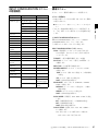
PRESET VALUE
MANUAL... [B1]
MANUAL ADJUST
[B] COLOR TEMP ADJ メニュー
PRESET VALUE:INPUT CONFIGURATION メ
ニューで設定している色温度データが表示されます。
調整する色温度データを変更する場合は D93、D65、
D61、USER1、USER2、USER3、USER4、USER5 か
ら選択します。
D93、D65、D61 データが変更されている場合は、
D93*、D65*、D61* と表示されます。
[B11]
ORIGINAL VALUE
色温度データを変更した場合
色温度データを変更し、MENU ボタンを押してメイン
CONT/BRT HOLD
AUTO... [B2]
AUTO ADJUST
メニューに戻るとき、次の変更確認メッセージが表示
されます。
[B21]
TARGET COLOR
CHANGE INPUT CONFIG?
COLOR TEMP PRESET
TEMP
X
DXX*
Y
第 2 章 メニュー
SIGNAL
t USERX
(変更前色温度データ)t(変更後色温度データ)
LOW LIGHT (20 IRE)
OK:色温度データを変更する場合は ENTER (Ent) ボ
タンを押します。
HIGH LIGHT
(100 IRE)
INPUT CONFIGURATION メニューで設定している
色温度データが変更後の色温度データに置き換えられ
PROBE
CONT/BRT HOLD
COPY FROM... [B3]
PRESET VALUE...
[B31]
OTHER MONITOR...
OTHER MONITOR...
[B32]
[B321]
MEMORY STICK...
MEMORY STICK
[B33]
[B331]
ます。
CANCEL:変更しない場合は MENU ボタンを押し、
メインメニューに戻ります。
色温度データの調整値は残りますが、INPUT
CONFIGURATION メニューで設定している色温度
データは置き換えられません。
RESTORE
FACTORY DATA
[B4]
ANALYZE [B5]
構成メニュー
以下に、メニュー番号順に構成メニューを説明します。
メニューの見かた
• 本書では各メニューに付けた番号(例:A11)は、画面に
は表示されません。
◆ 詳しくは「メニュー番号について」(29 ページ)をご覧くださ
い。
• 「k」は、設定操作後の移行先メニューの番号を示しま
す。「k」を記していない場合は、そこで設定操作が完了
します。
◆ INPUT CONFIGURATION メニューについては、「[C] 入力
チャンネルの設定 − INPUT CONFIGURATION メニュー」
(40 ページ)をご覧ください。
MANUAL...:色温度を MANUAL つまみで調整します。
k[B1]
AUTO...:色温度を自動調整します。k[B2]
COPY FROM...:他の色温度データをコピーします。
k[B3]
RESTORE FACTORY DATA:色温度データを工場出
荷時の設定値に戻します。k[B4]
ANALYZE:色度、輝度を測定します。k[B5]
[B1] MANUAL ... メニュー
MANUAL ADJUST:ゲインとバイアスをつまみで調整
します。k[B11]
ORIGINAL VALUE:調整の初期値を設定します。
初期値は D93、D65、D61、USER1、USER2、
USER3、USER4、USER5 から選択できます。
D93、D65、D61 データが変更されている場合は、
D93*、D65*、D61* と表示されます。
[B] 色温度の調整 ー COLOR TEMP ADJ メニュー
37
SIGNAL:調整に使う白色信号を選択します。
INT:内部信号を使用。ゲイン、バイアスの調整と同
期して 100IRE と 20IRE の信号が自動的に切り換
わります。
EXT:外部入力信号を使用。ゲイン、バイアスの調整
時に、調整に使う信号を入力します。(工場出荷時
の設定)
CONT/BRT HOLD:ホワイトバランスのマニュアル調
第 2 章 メニュー
整で、コントラスト、明るさの設定を調整値にするか
センター値にするか(ON または OFF)を選択しま
す。
ON:コントラスト、明るさの設定値を変更せず、調
整します。(工場出荷時の設定)
OFF:ホワイトバランス調整時、コントラスト、明る
さの設定はセンター値(1000)となります。
調整後もセンター値(1000)のままです。
[B11] MANUAL ADJUST メニュー
ゲイン、バイアスの調整をすることができます。
ゲイン調整、バイアス調整の切り換えは、UP/DOWN ボタ
ンで行います。
現在画面に表示されている画像に設定されている色温度に
対応する MANUAL メニュー画面を表示させることができ
ます。
[B2] AUTO... メニュー
色温度を自動調整します。
AUTO ADJUST:調整を開始します。k[B21]
TARGET COLOR TEMP:使いたい調整値を選択しま
す。
D93、D65、D61、ANY から選択できます。
X:x 座標を入力します。
Y:y 座標を入力します。
LOW LIGHT (20IRE):ローライト側の輝度(cd/m2)
を入力します。
HIGHT LIGHT (100IRE):ハイライト側の輝度
(cd/m2)を入力します。
PROBE:色温度の自動調整で使用するプローブを選択し
ます。
プローブの選択
各項目の調整に使うつまみ
BKM-14L:色温度の調整に BKM-14L を使う。
CA-100:色温度の調整に CA-100 または CA-
調整終了後、ENTER (Ent) ボタンを押すと、調整値が確定
されます。
100plus を使う。
PM 5639:色温度の調整に PM 5639 を使う。
RED:CONTRAST KNOB(CONTRAST つまみで R
のゲインまたはバイアスを調整する。)
TF6:色温度の調整に TF6 を使う。
SLS 9400-FC:色温度の調整に SLS 9400-FC を使
GREEN:BRIGHT KNOB(BRIGHT つまみで G のゲイ
ンまたはバイアスを調整する。)
う。
• BKM-14L をご使用の際に、AUTO ADJUST メ
BLUE:CHROMA KNOB(CHROMA つまみで B のゲ
インまたはバイアスを調整する。)
LUMINANCE:PHASE KNOB(PHASE つまみで輝度
を調整する。)
RED/GREEN/BLUE を調整前の値に戻すには
RED/GREEN/BLUE を調整時、対応する MANUAL 調整
ボタンを押すと調整前の値に戻ります。
RED、GREEN、BLUE をすべて調整前の値に戻すには、
PHASE の MANUAL 調整ボタンを押します。
ご注意
ENTER (Ent) ボタンを押して確定した後は、MANUAL 調
整ボタンを押しても変わりません。
途中で中止するには
MENU ボタンを押します。調整したデータがキャンセルさ
れます。
調整データを確定するには
ENTER (Ent) ボタンを押します。
38
COL TEMP(ショートカット)ボタンについて
[B] 色温度の調整 ー COLOR TEMP ADJ メニュー
ニューが実行できない場合は、1度コネクターを差
し直してください。
• KONICA MINOLTA 社製 CA-100plus をご使用の際
は、RS-232C 通信環境を CA-100 互換モードに設定
してください(BAUD RATE 設定:9600 bps)。
• THOMA 社製 TF6 をご使用の際は、TF6 の PRINT 設
定メニューを OFF に設定してください。
CONT/BRT HOLD:ホワイトバランスの自動調整後に、
コントラスト、明るさの設定を調整値にするかセン
ター値にするか(ON または OFF)を選択します。自
動調整時は、コントラスト、明るさの設定はセンター
値(1000)となります。
ON:ホワイトバランス調整後、コントラスト、明る
さの設定は元の調整値に戻る。(工場出荷時の設
定)
OFF:ホワイトバランス調整後、コントラスト、明る
さの設定はセンター値(1000)のままとなる。
次の手順でメニューを操作し、自動調整を開始させます。
前回調整時の値を使用する場合は、1、2、3 の操作をす
る必要はありません。AUTO ADJUST を選んでください。
1 TARGET COLOR TEMPで使いたい調整値を選択する。
D93:D93 の色温度をコピーする。
ANY を選択した場合は、X および Y の項目を選び、
CIE1931 色度座標の x 座標、y 座標の値を入力してくださ
い。
D65:D65 の色温度をコピーする。
D61:D61 の色温度をコピーする。
USER1 ∼ 5:USER1 ∼ 5 の色温度をコピーする。
2 LOW LIGHT および HIGH LIGHT の値を入力する。
3 プローブを選択する(工場出荷時は BKM-14L に設定さ
れています。
)
4 AUTO ADJUST を選択する。
D93、D65、D61 データが変更されている場合は、D93*、
D65*、D61* と表示されます。
[B33] MEMORY STICK... メニュー
コピー元に使う“メモリースティック”内のファイルを選
[B21] AUTO ADJUST メニュー
[B2] AUTO... メニューで AUTO ADJUST を選択すると表示
[B331] MEMORY STICK メニュー
されます。
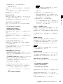
SET PROBE ON CURSOR が表示されます。
コピーするデータを選択します。
D93、D65、D61、USER1、USER2、USER3、USER4、
プローブをモニター画面の中央部に置くと調整が始まりま
す。(自動調整には時間を要します。終了するまでお待ちく
USER5 から選択します。
D93:D93 の色温度をコピーする。
ださい。)
調整を実行しない / 中止する場合
MENU ボタンを押します。
[B3] COPY FROM... メニュー
色温度データのコピー元を選択します。
PRESET VALUE...:モニター内の他のデータをコピー
します。k[B31]
OTHER MONITOR...:他のモニターのデータをコピー
します。k[B32]
MEMORY STICK...:“メモリースティック”内のファイ
ルをコピーします。k[B33]
[B31] PRESET VALUE... メニュー
コピーするデータを選択します。
D93、D65、D61、USER1、USER2、USER3、USER4、
USER5 から選択します。
D93:D93 の色温度をコピーする。
D65:D65 の色温度をコピーする。
D61:D61 の色温度をコピーする。
USER1 ∼ 5:USER1 ∼ 5 の色温度をコピーする。
D93、D65、D61 データが変更されている場合は、D93*、
D65*、D61* と表示されます。
[B32] OTHER MONITOR... メニュー
コピー元に使うモニターの ID No. を指定します。
MONITOR ID...:ID No. を入力します。k[B321]
NETWORK スイッチを PEER TO PEER に設定したときは
選択できません。
[B321] OTHER MONITOR... メニュー
コピーするデータを選択します。
D93、D65、D61、USER1、USER2、USER3、USER4、
USER5 から選択します。
第 2 章 メニュー
択します。k[B331]
D65:D65 の色温度をコピーする。
D61:D61 の色温度をコピーする。
USER1 ∼ 5:USER1 ∼ 5 の色温度をコピーする。
D93、D65、D61 データが変更されている場合は、D93*、
D65*、D61* と表示されます。
[B4] RESTORE FACTORY DATA メニュー
色温度データを工場出荷時の設定値に戻します。
USER1 ∼ 5 または工場出荷時の設定値のときは選択できま
せん。
次のメッセージが表示されます。
RESTORE FACTORY DATA?
OK:リセットを実行する場合 ENTER (Ent) ボタンを押
します。
CANCEL:リセットを実行しない場合 MENU ボタンを
押します。
[B5] ANALYZE メニュー
BKM-14L で測定した色度座標および輝度値が表示されま
す。
SET PROBE ON CURSOR
BKM-14L をモニターの画面の中央部に吸着します。
キャリブレーション終了後、BKM-14L は、ANALYZE 動
作が可能になります。
ANALYZE を実行しない場合
MENU ボタンを押します。
ご注意
• BKM-14L のキャリブレーション前に、R、G、B のビーム
をカットしたり、マーカーを表示させたりしないでくだ
さい。BKM-14L が検出されない可能性があります。
• ANALYZE 実行中は、BKM-14L を OPTION 端子から抜か
ないでください。万一、画面上に何も表示されなくなっ
た場合は、MENU ボタンを押してください。COLOR
TEMP ADJ メニューに戻ることができます。
[B] 色温度の調整 ー COLOR TEMP ADJ メニュー
39
083:1080/50I
[C] 入力チャンネルの設定
− INPUT
CONFIGURATION
メニュー
084:576/50P
085:480/60P
086:1080/60I
087:1035/60I
088:720/50P
089:720/60P
91 ∼ 97 チャンネルの割り当て
第 2 章 メニュー
91 ∼ 97 のチャンネル番号は内蔵信号に割り当てられていま
概要
す。最後に選択されていた信号システムの内蔵信号が表示
されます。電源 ON のとき、内蔵信号で出画した場合、信
入力信号に関する各種データを設定するメニューです。
号システムは 480/60I となります。
入力データはチャンネルごとに設定します。まず数値ボタ
ンを使ってチャンネル番号(1 ∼ 30)を指定し、その後、
091:プルージ信号
INPUT CONFIGURATION メニューで以下のデータを設定
します。
093:100%白信号
• 信号の種類を指定する(FORMAT... メニュー)
• スロット番号を指定する(SLOT NO メニュー)
• 入力端子番号を指定する(INPUT NO メニュー)
• 画像のアスペクト比を設定する(SCREEN ASPECT メ
ニュー)
• スキャンサイズを選択する(SCAN SIZE メニュー)
• 同期信号を選択する(SYNC MODE メニュー)
• 色温度を設定する(COLOR TEMP メニュー)
• 画像調整のプリセットを選択する(PICTURE PRESET
メニュー)
• マトリクスを設定する(MATRIX... メニュー)
• アパーチャー補正の有無を選択する(APERTURE メ
ニュー)
• アパーチャー補正量を指定する(VALUE メニュー)
• Y/C 分離フィルターを選択する(YC SEP メニュー)
• NTSC COMB フィルタを設定する(NTSC COMB
FILTER メニュー)
• マーカーの表示の有無を選択する(MARKER DISPLAY
メニュー)
092:20%グレー信号
094:5 段階グレースケール信号
095:クロスハッチ信号
096:ドット信号
097:0%黒信号
スロット番号、入力番号の割り付け
現在のチャンネルを、どのスロットに割り付けるかを設定
します。
スロット番号は次のようになります。
OPTION1(モニター外側のスロット)
OPTION2
OPTION3(モニター中央のスロット)
入力番号は次のようになります。
BKM-61D が取り付けられているとき(SDI D1、SDI
D1/D2 AUTO、SDI D2 NTSC、SDI D2 PAL 信号のと
き):DIGITAL1 または 2
BKM-61D が取り付けられているとき(COMPOSITE
AUTO、NTSC、PAL、PAL-M、SECAM 信号などのア
ナログコンポジット信号のとき):COMPOSITE1、2 また
は3
• マーカーの表示モードを選択する(MODE... メニュー)
• 画面の水平方向の位置を調整する(H PHASE メニュー)
BKM-62HS が取り付けられているとき(SDI HD/D1
AUTO、HD-SDI、SDI D1 信号のとき):DIGITAL1 また
• チャンネル名をつける(CHANNEL NAME... メニュー)
• 他のデータをコピーする(COPY FROM... メニュー)
は2
ご注意
80 ∼ 89 チャンネルの割り当て
80 ∼ 89 のチャンネル番号は内蔵信号の信号システム切り換
FORMAT... が次の場合は入力信号を選択することはできま
せん。
え用に割り当てられています。
80 ∼ 89 チャンネルの選択は、91 ∼ 97 チャンネルの選択後
- BKM-61D が取り付けられていて Analog Y/C 信号のとき
- BKM-62HS が取り付けられていて Dual Link HD-SDI 信号
のみ有効となり、選択された信号システムの内蔵信号が出
力されます。
のとき
- BKM-68X が取り付けられていて Analog Component また
は Analog RGB 信号のとき
080:575/50I
081:480/60I
082:1080/48I
40
[C] 入力チャンネルの設定 − INPUT CONFIGURATION メニュー
INPUT CONFIGURATION メニュー
の階層構造
第1層
第2層
第3層
CHxx
FORMAT... [C1]
構成メニュー
以下に、メニュー番号順に構成メニューを説明します。
メニューの見かた
• 本書では各メニューに付けた番号(例:A11)は、画面に
SDI/HD-SDI... [C11]
は表示されません。
DUAL LINK HD-SDI...
[C12]
•「k」は、設定操作後の移行先メニューの番号を示しま
す。「k」を記していない場合は、そこで設定操作が完了
YC... [C14]
COMPONENT... [C15]
します。
SLOT NO
INPUT NO
[C] INPUT CONFIGURATION メニュー
SCREEN ASPECT
INPUT CONFIGURATION(1/2)メニューと INPUT
CONFIGURATION(2/2)メニューがあります。
SCAN SIZE
SYNC MODE
第 2 章 メニュー
◆ 詳しくは「メニュー番号について」(29 ページ)をご覧くだ
さい。
COMPOSITE... [C13]
入力信号のデータをチャンネルごとに設定します。
COLOR TEMP
PICTURE
INPUT CONFIGURATION(1/2)メニュー
PRESET
CHxx:現在選択しているチャンネルが表示されます。
以下の設定は、そのチャンネルに入力される信号の
MATRIX... [C2]
APERTURE
データになります。
VALUE
YC SEP
FORMAT...:信号の種類を選択します。k[C1]
NTSC COMB
SLOT NO:オプションスロット番号(OPTION1 ∼ 3)
FILTER
を選択します。
MARKER
INPUT NO:入力端子番号を選択します。
DISPLAY
SCREEN ASPECT:アスペクト(16:9、4:3、LAST)
を設定します。
MODE... [C3]
H PHASE
16:9:アスペクト比を 16:9 に設定する。(工場出荷時
の設定)
CHANNEL
NAME... [C4]
COPY FROM... [C5] OTHER CH... [C51]
OTHER MONITOR... [C52] OTHER
MONITOR [C521]
MEMORY STICK... [C53]
MEMORY STICK
[C531]
4:3:アスペクト比を 4:3 に設定する。
LAST:前回の設定を使用する。
SCAN SIZE:スキャンサイズ(NORMAL、UNDER、
LAST)を設定します。
NORMAL:オーバースキャンに設定する。(工場出
荷時の設定)
UNDER:アンダースキャンに設定する。
LAST:前回の設定を使用する。
SYNC MODE:同期信号(INT、EXT、LAST)を設定
します。
INT:内部同期信号を使う。(工場出荷時の設定)
EXT:外部同期信号を使う。
LAST: 前回の設定を使用する。
COLOR TEMP:色温度(D93、D65、D61、USER1 ∼
5)を選択します。
D93、D65、D61 データが変更されている場合は、
D93*、D65*、D61* と表示されます。
[C] 入力チャンネルの設定 − INPUT CONFIGURATION メニュー
41
PICTURE PRESET:画像調整プリセット(PRESET1
∼ PRESET5)を選択します。(工場出荷時は
PRESET1)
MATIRIX...:信号システムごとのマトリクスを設定しま
す。k[C2]
INPUT CONFIGURATION(2/2)メニュー
APERTURE:アパーチャー補正をするかどうか(OFF、
ON、LAST)を設定します。
ご注意
対応する入力端子またはデコーダーがない場合は、選択で
きません(カーソルを合わせようとしてもスキップされま
す)。
[C11] SDI/HD-SDI... メニュー
シリアルデジタル信号のフォーマット(SDI またはシング
ルリンクの HD-SDI)を選択します。
第 2 章 メニュー
OFF:アパーチャー補正をしない。
(工場出荷時の設
定)
HD-SDI/D1 AUTO:BKM-62HS 装着時に選択できま
ON:アパーチャー補正をする。
LAST:前回の設定を使用する。
HD SDI:BKM-62HS 装着時に選択できます。
す。
D1:BKM-61D、BKM-62HS 装着時に選択できます。
VALUE:アパーチャー補正量(0 ∼ 200)を入力します。
(工場出荷時は 000)
D1/D2 AUTO:BKM-61D 装着時に選択できます。
YC SEP:Y/C 分離フィルターを選択します。
COMB:くし型フィルターを選択する。
(工場出荷時
D2 PAL:BKM-61D 装着時に選択できます。
の設定)
BPF/TRAP:BPF/TRAP を選択する。
NTSC COMB FILTER:NTSC COMB フィルタ(3
LINES、3D)を設定します。
(工場出荷時は 3 LINES)
MARKER DISPLAY:マーカーを表示するかどうか
(OFF、ON)を設定します。
(工場出荷時は OFF)
MODE...:MARKER MODE メニューを表示します。
マーカーのアスペクトやセーフエリア、セーフタイト
ルなどを設定します。k[C3]
H PHASE:画面の水平方向の位置を調整(− 100 ∼
+100*)します。(工場出荷時は 000)
* 可変範囲を超えると、数値は変わりますが、画面の
水平位置は変わりません。
CHANNEL NAME...:CHANNEL NAME メニューを表
示します。チャンネル名を付けます。k[C4]
COPY FROM...:COPY FROM メニューを表示します。
他のチャンネルデータをコピーします。k[C5]
[C1] FORMAT... メニュー
信号の種類を選択します。
SDI/HD-SDI...:シリアルデジタル信号 k[C11]
DUAL LINK HD-SDI...:デュアルリンクの HD-SDI 信号
k[C12]
COMPOSITE...:アナログコンポジット信号 k[C13]
D2 NTSC:BKM-61D 装着時に選択できます。
NTSC SETUP LEVEL:NTSC セットアップレベル
(0%、7.5%)を設定します。(工場出荷時は、BVMA20F1M/A20F1A:0%、BVM-A20F1U:7.5%)
FILTER SW:画面を白黒表示に設定しているとき、Y/C
分離フィルタを動作させるかどうか(OFF、ON)を
設定します。(工場出荷時は OFF)
ACC SW:オートクロマコントロールの ON、OFF を設
定します。(工場出荷時は OFF)
◆ HD-SDI、1125/60I 入力において、1080/60I、1035/60I の選択は
自動的に行われます。
[C12] DUAL LINK HD-SDI... メニュー
HD-SDI の信号フォーマット(デュアルリンクの HD-SDI)
を選択します。BKM-62HS 装着時に選択できます。
4:4:4 YPBPR
4:4:4 RGB
[C13] COMPOSITE... メニュー
コンポジット信号のフォーマットを選択します。BKM-61D
装着時に選択できます。
AUTO:入力された信号に応じて自動的に切り換えます。
フォーマットの自動切り換えは、フォーマットの判別
のため数秒かかることがあります。フォーマットが決
まっているときは、そのフォーマットに設定すること
をおすすめします。
YC...:アナログ Y/C 信号 k[C14]
NTSC
COMPONENT...:アナログコンポーネントまたはアナ
ログ RGB 信号 k[C15]
PAL
PAL-M
SECAM
42
[C] 入力チャンネルの設定 − INPUT CONFIGURATION メニュー
NTSC SETUP LEVEL:NTSC セットアップレベル
(0%、7.5%)を設定します。(工場出荷時は、BVMA20F1M/A20F1A:0%、BVM-A20F1U:7.5%)
FILTER SW:画面を白黒表示に設定しているとき、Y/C
分離フィルタを動作させるかどうか(OFF、ON)を
設定します。(工場出荷時は OFF)
ACC SW:オートクロマコントロールの ON、OFF を設
定します。(工場出荷時は OFF)
に選択できます。
タを設定します。(工場出荷時は ITU601)
それぞれ ITU601、SMPTE 240M、ITU709 または USER1
∼ 5 を選択することができます。
ITU601、SMPTE 240M、ITU709 データが変更されている
場合は ITU601*、SMPTE 240M*、ITU709* と表示されま
す。
ご注意
[C1] FORMAT メニューで設定している信号フォーマットが
4:4:4 RGB または RGB のとき、MATRIX メニューは選択で
きません。
AUTO:入力された信号に応じて自動的に切り換えます。
フォーマットの自動切り換えは、フォーマットの判別
のため数秒かかることがあります。フォーマットが決
まっているときは、そのフォーマットに設定すること
をおすすめします。
NTSC
PAL
[C3] MODE... メニュー
マーカーのアスペクトやセーフエリア、セーフタイトルな
どを設定します。入力信号に同期信号が無い場合、または
内蔵信号が使われている場合は、選択することができませ
ん。
PAL-M
MARKER MODE (1/3) メニュー
マーカーのアスペクトモードやアスペクトマーカー、ブラ
SECAM
ンキングなどの設定をします。
NTSC SETUP LEVEL:NTSC セットアップレベル
(0%、7.5%)を設定します。(工場出荷時は、BVMA20F1M/A20F1A:0%、BVM-A20F1U:7.5%)
ACC SW:オートクロマコントロールの ON、OFF を設
定します。(工場出荷時は OFF)
[C15] COMPONENT... メニュー
コンポーネント信号のフォーマットまたは RGB 信号の
フォーマット(YPBPR または RGB)を選択します。BKM68X 装着時に選択できます。
COMPONENT LEVEL:COMPONENT レベル
(SMPTE/EBU-N10、BETACAM)を設定します。
(工場出荷時は SMPTE/EBU-N10)
BETACAM SETUP LEVEL:BETACAM セットアップ
レベル(0%、7.5%)を設定します。
(工場出荷時は、
BVM-A20F1M/A20F1A:0%、BVM-A20F1U:7.5%)
1125/60I SYSTEM:1125/60I 入力時の有効走査
線(1080I(有効走査線 1080 ライン)、1035I(有効走
査線 1035 ライン)
)の設定をします。(工場出荷時は
1080I)
[C2] MATIRIX... メニュー
信号システムごとに使用するマトリクスを設定します。
1080/720:1080I、720P のマトリクスデータを設定し
ます。(工場出荷時は ITU709)
1035:1035I のマトリクスデータを設定します。
(工場
出荷時は SMPTE 240M)
第 2 章 メニュー
[C14] YC... メニュー
Y/C 信号のフォーマットを選択します。BKM-61D 装着時
480/576:480I、480P、575I、576P のマトリクスデー
ASPECT MODE:マーカーのアスペクト比を設定しま
す。
16:9、15:9、14:9、13:9、4:3、2.39:1、2.35:1、1.85:1、
1.66:1、VARIABLE から選択することができます。
(工場出荷時は 16:9)
ASPECT:ASPECT MODE で VARIABLE を選択した
とき設定します。
1.00 ∼ 3.00 に設定できます。(工場出荷時は 1.78)
H POSITION:マーカーの水平方向の表示位置を設定し
ます。
− 100 ∼ +100 に設定できます。(工場出荷時は 000)
MARKER BRIGHT:マーカーの輝度を設定します。
90IRE または 40IRE に設定できます。(工場出荷時は
90IRE)
このメニューで設定したデータは全チャンネル共通に
適用されます。
ASPECT MARKER:アスペクトマーカーを表示するか
どうかを設定します。
OFF(表示しない)または ON(表示する)に設定し
ます。(工場出荷時は OFF)
LINE:ASPECT MARKER の設定が ON のときアスペク
トマーカーのラインの太さを設定します。
THICK(太い線)または THIN(細い線)に設定でき
ます。(工場出荷時は THICK)
COLOR:ASPECT MARKER の設定が ON のときアス
ペクトマーカーの色を設定します。
[C] 入力チャンネルの設定 − INPUT CONFIGURATION メニュー
43
WHITE(白)
、RED(赤)
、GREEN(緑)、BLUE
(青)
、YELLOW(黄)、CYAN(シアン)
、
MAGENTA(マゼンタ)から選択することができま
す。(工場出荷時は WHITE)
ASPECT BLANKING:エリア外のブランキングを選択
します。
OFF(ブランキングを解除する)または ON(ブラン
キングする)に設定します(工場出荷時は OFF)。
第 2 章 メニュー
MODE:ASPECT BLANKING の設定が ON のときブラ
ンキングのモードを設定します。
BLACK(ブランキング)または HALF(ハーフブラ
ンキング)に設定できます。(工場出荷時は HALF)
MARKER MODE (2/3) メニュー
セーフエリアマーカーやセンターマーカーの設定をします。
SAFE AREA MARKER:セーフエリアの表示モードを
設定します。
OFF(表示しない)または ON(表示する)に設定し
ます。(工場出荷時は ON)
CENTER MARKER:センターマーカーの表示モードを
設定します。
OFF(表示しない)または ON(表示する)に設定し
ます。(工場出荷時は OFF)
MODE:CENTER MARKER の設定が ON のとき、セン
ターマーカーの種類を選択します。
SHORT(短い)または LONG(長い)に設定できま
す。(工場出荷時は SHORT)
ご注意
セーフエリアの大きさは、ASPECT MODE、16:9 ボタンの
ON/OFF の状態により異なります。
例:セーフエリアサイズが 80%、ASPECT MODE が
16:9、4:3 のとき
16:9 ボタン ON のとき
ASPECT
MODE
16:9
16:9 ボタン OFF のとき
80%
80%
80%
80%
MODE:SAFE AREA MARKER の設定が ON のとき、
SAFE AREA MARKER の形を選択します。
SHAPE A、SHAPE B、SHAPE C から選択します。
(工場出荷時は SHAPE A)
ASPECT
MODE
4:3
SHAPE A
MARKER MODE (3/3) メニュー
セーフタイトルの項目を設定します。
SHAPE B
SAFE TITLE DISPLAY:セーフタイトルの表示モード
を設定します。
OFF(表示しない)または ON(表示する)に設定し
ます。(工場出荷時は ON)
SHAPE C
WIDTH:SAFE TITLE DISPLAY の設定が ON のとき、
セーフタイトルの幅を設定します。
005 ∼ 050 (%) に設定できます。(工場出荷時は 020)
HEIGHT:SAFE TITLE DISPLAY の設定が ON のと
き、セーフタイトルの高さを設定します。
AREA SIZE:SAFE AREA MARKER の設定が ON の
とき、セーフエリアモードのサイズを設定します。
80%、88%、90%、93%、VARIABLE から選択するこ
とができます。(工場出荷時は 80%)
WIDTH:AREA SIZE で VARIABLE を選択したとき、
セーフエリアマーカーの幅を設定します。
050 ∼ 100 (%) に設定できます。
(工場出荷時は 080)
HEIGHT:AREA SIZE で VARIABLE を選択したとき、
セーフエリアマーカーの高さを設定します。
050 ∼ 100 (%) に設定できます。
(工場出荷時は 080)
44
[C] 入力チャンネルの設定 − INPUT CONFIGURATION メニュー
005 ∼ 050 (%) に設定できます。(工場出荷時は 010)
H POSITION:SAFE TITLE DISPLAY の設定が ON の
とき、セーフタイトルの水平方向の表示位置を設定し
ます。
000 ∼ 100 (%) に設定できます。(工場出荷時は 015)
V POSITION:SAFE TITLE DISPLAY の設定が ON の
ときセーフタイトルの垂直方向の表示位置を設定しま
す。
000 ∼ 100 (%) に設定できます。(工場出荷時は 015)
[C4] CHANNEL NAME... メニュー
チャンネル名を付けます。デフォルトの名前から選択する
か新規に入力します。
PROG:プログラム送出信号
EDIT:編集機からの信号
CAM:カメラからの信号
VTR:VTR からの信号
[D] システムの設定
− SYSTEM
CONFIGURATION
メニュー
PREV:プレビューモニター
は先頭の 8 文字までが表示されます)。
[C5] COPY FROM メニュー
概要
ネットワークやパラレルリモートコントロール機能などシ
ステムに関する設定をするメニューです。
コピー元を選択します。
OTHER CH...:モニター内の他のデータをコピーしま
す。k[C51]
OTHER MONITOR...:他のモニターのデータをコピー
します。k[C52]
MEMORY STICK...:“メモリースティック”内のファイ
ルを選択し、そのデータをコピーします。k[C53]
[C51] OTHER CH... メニュー
コピー元に使うチャンネル番号を指定します。
CH NO:チャンネル番号を入力します。
[C52] OTHER MONITOR... メニュー
コピー元に使うモニターの ID No. を指定します。
MONITOR ID:ID No. を入力します。k[C521]
第 2 章 メニュー
NEW NAME:新規の名前を入力する(20 文字まで入力
可能、ただし INPUT CONFIGURATION メニューで
以下のデータを設定します。
• ネットワークによるリモートコントロール機能を設定す
る(NETWORK... メニュー)
• パラレルリモートコントロール機能の設定をする
(PARALLEL REMOTE... メニュー)
• 主電源や MONITOR I/1 スイッチを入れたときのモニ
ターの状態を設定をする(POWER... メニュー)
• ブランキング関連の設定をする(BLANKING
SETTINGS... メニュー)
• 画面に表示させる情報を設定する(ON SCREEN SET...
メニュー)
• パスワードの変更や割り付けを設定する
(PASSWORD... メニュー)
• メインテナンス用の設定をする(MAINTENANCE... メ
ニュー)
NETWORK スイッチを PEER TO PEER に設定したときは
選択できません。
[C521] OTHER MONITOR メニュー
選択したモニターのどのチャンネルをコピー元にするか指
定します。
CH NO:チャンネル番号を入力します。
[C53] MEMORY STICK... メニュー
コピー元に使う“メモリースティック”内のファイルを選
択します。k[C531]
[C531] MEMORY STICK メニュー
指定したファイルのどのチャンネルをコピー元にするか指
定します。
CH NO:チャンネル番号を入力します。
[D] システムの設定 − SYSTEM CONFIGURATION メニュー
45
SYSTEM CONFIGURATION メ
ニューの階層構造
[D] SYSTEM CONFIGURATION メニュー
NETWORK...:ネットワークによるリモートコントロー
ル機能を設定します。k[D1]
PARALLEL REMOTE...:パラレルリモートコントロー
第1層
第2層
NETWORK... [D1]
MONITOR ID
第3層
POWER...:主電源を入れたり、外部操作により電源を入
GROUP ID
れたときのモニターの状態を設定します。k[D3]
NETWORK
BLANKING SETTINGS...:ブランキングに関連する設
SETTINGS... [D11]
定をします。k[D4]
第 2 章 メニュー
NETWORK SW
SNMP SETTINGS...
ON SCREEN SET...:画面に表示させる情報を設定しま
[D12]
PARALLEL REMOTE...
PARALLEL
[D2]
REMOTE
POWER... [D3]
ル機能の設定をします。k[D2]
す。k[D5]
PASSWORD...:パスワードの変更や割り付けを設定し
1 PIN... ∼ 8 PIN...
PARALLEL
[D21]
REMOTE [D211]
ます。k[D6]
MAINTENANCE...:メインテナンス用の設定をします。
k[D7]
STANDBY MODE
POWER ON
[D1] NETWORK... メニュー
STATUS
DEFAULT CH
MONITOR ID:モニター ID No. を入力します。
DEGAUSS DELAY
BLANKING
ANCILLARY
SETTINGS... [D4]
DATA
01 ∼ 99(工場出荷時は 01)から選択します。
GROUP ID:グループ ID No. を入力します。
01 ∼ 99(工場出荷時は 01)から選択します。
VITS BLK
ON SCREEN SET... [D5]
FORMAT
NETWORK SETTINGS...:IP アドレス、サブネットマ
DISPLAY
スク、デフォルトゲートウェイを設定します。
k[D11]
POSITION
CH NO
NETWORK SW:NETWORK スイッチの設定状態
(LAN、PEER TO PEER)を表示します。
POSITION
CH NAME
POSITION
PASSWORD... [D6]
CHANGE
CHANGE
PASSWORD... [D61]
PASSWORD [D611]
APPLY
APPLY
PASSWORD... [D62]
PASSWORD [D621]
MAINTENANCE... [D7]
構成メニュー
以下に、メニュー番号順に構成メニューを説明します。
メニューの見かた
• 本書では各メニューに付けた番号(例:A11) は、画面に
は表示されません。
◆ 詳しくは「メニュー番号について」(29 ページ)をご覧くださ
い。
• 「k」は、設定操作後の移行先メニューの番号を示しま
す。「k」を記していない場合は、そこで設定操作が完了
します。
46
[D] システムの設定 − SYSTEM CONFIGURATION メニュー
SNMP SETTINGS...:CONTACT、NAME、
LOCATION、TRAP を設定します。k[D12]
[D11] NETWORK SETTINGS... メニュー
IP ADDRESS:IP アドレスを設定します。( 工場出荷時
は「192.168.000.001」)
SUBNET MASK:サブネットマスクを設定します。( 工
場出荷時は「255.255.255.000」)
DEFAULT GATEWAY:デフォルトゲートウェイを設
定するかどうか(OFF、ON)を選択します。( 工場出
荷時は OFF)
ADDRESS:デフォルトゲートウェイを設定します。
( 工場出荷時は「---.---.---.---(無設定)」)
CANCEL:変更、確定された設定を変更前に戻します。
CONFIRM:変更、確定された設定を保存、反映します。
各ピンの工場出荷時の設定
ご注意
1 PIN:CH01
NETWORK スイッチを PEER TO PEER に設定した場合、
IP アドレスは、表示にかかわらず「192.168.000.001」に固
定されます。
NETWORK スイッチを LAN に設定すると、表示された IP
アドレスが有効となります。
[D12] SNMP SETTINGS... メニュー
使用できる記号は「(」
「)」
「.」「−」
「+」
「/」
「%」
「*」「#」
「_」
「$」
「(スペース)
」の 12 種類で
す。
NAME メニュー:管理用の情報(デバイス ID)を設定
します。
NEW NAME:新規の名前を入力する(20 文字まで)。
使用できる記号は「(」
「)」
「.」「−」
「+」
「/」
「%」
「*」「#」
「_」
「$」
「(スペース)
」の 12 種類で
す。
LOCATION メニュー:設置場所の情報を設定します。
NEW NAME:新規の名前を入力する(20 文字まで)。
使用できる記号は「(」
「)」
「.」「−」
「+」
「/」
「%」
「*」「#」
「_」
「$」
「(スペース)
」の 12 種類で
す。
TRAP メニュー:情報の送信先を設定します。TRAP1
と TRAP2 の 2 か所の設定ができます。
TRAP1:IP アドレスを設定します。
(工場出荷時は
「000.000.000.000」
)
3 PIN:EXT SYNC
4 PIN:MONO
5 PIN:MARKER
6 PIN:未設定
7 PIN:未設定
8 PIN:TALLY
[D211] PARALLEL REMOTE メニュー
PARALLEL REMOTE (1/2) メニュー
CH01 ∼ 30:チャンネル番号の割り付け。割り付けた
いチャンネル番号を入力します。
----:未設定
UNDER SCAN:アンダースキャンするかどうかの選択
16:9:アスペクト比を 16:9 にするかどうかの選択
H DELAY:水平同期信号を表示するかどうかの選択
V DELAY:垂直同期信号を表示するかどうかの選択
EXT SYNC:外部同期信号に同期するかどうかの選択
COMB:くし形フィルターを使用するかどうかの選択
APERTURE:アパーチャー補正をするかどうかの選択
MONO:白黒画像にするかどうかの選択
PARALLEL REMOTE (2/2) メニュー
TRAP2:IP アドレスを設定します。
(工場出荷時は
「000.000.000.000」
)
BLUE ONLY:青信号のみを表示する(白黒表示 ) かど
うかの選択
CANCEL:変更、確定された設定を変更前の値に戻
します。
R OFF:赤のビームをカットするかどうかの選択
CONFIRM:変更、確定された設定を保存、反映しま
す。
B OFF:青のビームをカットするかどうかの選択
[D2] PARALLEL REMOTE... メニュー
PARALLEL REMOTE:パラレルリモートを使用するか
どうか(ON、OFF)を設定します。( 工場出荷時は
OFF)
1 PIN... ∼ 8 PIN...:PARALLEL REMOTE を ON に設
定したときのパラレルリモート端子の各ピンへの機能
を割り付けます。k[D21]
[D21] 1 PIN... ∼ 8 PIN... メニュー
選択したピンに機能を割り付けます。k[D211]
第 2 章 メニュー
CONTACT メニュー:管理責任者の情報を設定します。
NEW NAME:新規の名前を入力する(20 文字まで)。
2 PIN:CH02
G OFF:緑のビームをカットするかどうかの選択
CHROMA UP:クロマを 12 dB アップするかどうかの選
択
MARKER:チャンネルで設定したマーカーを表示するか
どうかの選択
TALLY:タリ−ランプを ON/OFF するかどうかの選択
DEGAUSS:デガウス動作を実行するかどうかの選択
POWER OFF:モニターの電源を入 / スタンバイ状態に
するかどうかの選択
◆ ピン接続については、
「各部の名称と働き」の PARALLEL
REMOTE 端子(14 ページ)についての説明をご覧ください。
[D] システムの設定 − SYSTEM CONFIGURATION メニュー
47
[D3] POWER... メニュー
CH NO:チャンネル番号の表示方法を選択します。
主電源を入れたり、外部操作により電源を入れたときのモ
ニターの状態を設定します。
AUTO: 一定時間表示後、自動的に消える。(工場出
荷時の設定)
ON: 常に表示される。
STANDBY MODE:MAIN POWER スイッチを ON に
したときの状態(ON、OFF) を選択します。
OFF:直ちに動作状態になります。
(工場出荷時の設
OFF: 表示されない。
POSITION:チャンネル番号の表示位置を選択します。
定)
ON:スタンバイ状態になります。
TOP LEFT: 左上
TOP CENTER: 中央上
TOP RIGHT: 右上(工場出荷時の設定)
BOTTOM LEFT: 左下
第 2 章 メニュー
POWER ON STATUS:電源投入時のチャンネル設定状
態(LAST、CH) を選択します。
BOTTOM CENTER: 中央下
BOTTOM RIGHT: 右下
LAST:前回電源を OFF にする直前のチャンネル設
定になります。(工場出荷時の設定)
CH:指定したチャンネル設定となります。
DEFAULT CH:POWER ON STATUS を CH に設定し
CH NAME:チャンネル名の表示方法を選択します。
AUTO: 一定時間表示後、自動的に消える。(工場出
荷時の設定)
ON: 常に表示される。
たとき指定チャンネル(01 ∼ 30)を選択します。(工
場出荷時は 01)
DEGAUSS DELAY:ほぼ出画した状態からデガウスを
開始するまでの時間(000 ∼ 255)を指定する。希望
の時間(秒)を入力します。(工場出荷時は 000)
OFF: 表示されない。
POSITION:チャンネル名の表示位置を選択します。
TOP LEFT: 左上(工場出荷時の設定)
TOP CENTER: 中央上
TOP RIGHT: 右上
[D4] BLANKING SETTINGS... メニュー
ブランキングに関連する設定をします。
BOTTOM LEFT: 左下
BOTTOM CENTER: 中央下
ANCILLARY DATA:シリアルデジタル信号内の補助
データを表示するかどうか(OFF、ON) を選択しま
す。(工場出荷時は ON)
VITS BLK:VITS 信号が画面上部に見えないようにする
ため、垂直方向ブランキングを設定します。
000 ∼ 127 の範囲で設定します。(工場出荷時は 000)
BOTTOM RIGHT: 右下
[D6] PASSWORD...
パスワードの変更や割り付けを設定します。
文字数は 4 文字で工場出荷時は「9999」に設定されていま
す。
CHANGE PASSWORD...:新しいパスワードを入力し
ます。k[D61]
APPLY PASSWORD...:メニューリストの各項目でパ
スワードの確認をするかどうかを設定します。
[D5] ON SCREEN SET... メニュー
画面に表示する項目を選択します。
FORMAT DISPLAY:信号システムの表示方法を選択し
ます。
AUTO:一定時間表示後、自動的に消える。
(工場出
荷時の設定)
ON:常に表示される。
k[D62]
[D61] CHANGE PASSWORD... メニュー
パスワードを変更します。
ENTER NEW PASSWORD:新しいパスワードを数字
ボタンで入力し、ENTER ボタンを押します。
k[D611]
OFF:表示されない。
POSITION:信号システムの表示位置を選択します。
TOP LEFT:左上
TOP CENTER:中央上
TOP RIGHT:右上
BOTTOM LEFT:左下(工場出荷時の設定)
BOTTOM CENTER:中央下
BOTTOM RIGHT:右下
48
[D] システムの設定 − SYSTEM CONFIGURATION メニュー
[D611] CHANGE PASSWORD メニュー
新しいパスワードを入力します。
RE-ENTER PASSWORD:確認のために作成したパス
ワードを再度入力して ENTER ボタンを押します。パ
スワードが登録されます。
修正するときは MENU ボタンを押します。
[D62] APPLY PASSWORD... メニュー
各メニューでパスワードを有効にするかどうかを設定しま
す。
PICTURE ADJ:YES または NO を選択します。
COLOR TEMP ADJ:YES または NO を選択します。
INPUT CONFIGURATION:YES または NO を選択し
[E] 設置調整
− INSTALLATION
SETTINGS メニュー
ます。
SYSTEM CONFIGURATION:YES または NO を選択
INDIVIDUAL ITEMS...:SYSTEM CONFIGURATION
メニューの各項目を表示します。k[D621]
概要
ランディング、画像の歪みなどの設置調整をするためのメ
ニューです。
INSTALLATION SETTINGS:YES または NO を選択
します。
FILE MANAGEMENT:YES または NO を選択します。
CONTROLLER:YES または NO を選択します。
KEY PROTECT:YES または NO を選択します。
[D621] APPLY PASSWORD メニュー
SYSTEM CONFIGURATION メニューの各項目でパスワー
ドを有効にするかどうかを設定します。
NETWORK:YES または NO を選択します。
PARALLEL REMOTE:YES または NO を選択します。
次の調整を実行できます。
• 地磁気の影響によるビームランディングのずれを補正す
る(LANDING ADJUST... メニュー)
第 2 章 メニュー
します。
• 画像の位置やサイズ、コンバージェンスを調整する
(ALIGNMENT... メニュー)
• CRT の色むらを調整する(DIGITAL UNIFORMITY
ADJ... メニュー)
ご注意
ビームランディング調整を行ってから、デジタルユニ
フォーミティ調整を行ってください。
POWER:YES または NO を選択します。
BLANKING SETTINGS:YES または NO を選択しま
す。
ON SCREEN SET:YES または NO を選択します。
[D7] MAINTENANCE... メニュー
サービス担当者用のメインテナンス用メニューが表示され
ます。
[E] 設置調整 − INSTALLATION SETTINGS メニュー
49
INSTALLATION SETTINGS メ
ニューの階層構造
第1層
第2層
LANDING
NS
ADJUST... [E1]
RESTORE FACTORY
ALIGNMENT... [E2]
ROTATION
第3層
•「k」は、設定操作後の移行先メニューの番号を示しま
す。「k」を記していない場合は、そこで設定操作が完了
します。
[E] INSTALLATION SETTINGS メニュー
LANDING ADJUST...:地磁気の影響によるビームラン
ディングのずれを調整します。k[E1]
DATA [E11]
ALIGNMENT...:画像の位置やサイズ、コンバージェン
スを調整します。k[E2]
第 2 章 メニュー
H PHASE
DIGITAL UNIFORMITY ADJ...:デジタルユニフォミ
ティの調整をします。k[E3]
V CENTER
H SIZE
V SIZE
[E1] LANDING ADJUST... メニュー
地磁気の影響によるビームランディングのずれを調整しま
SUB CONTRAST
H PIN
す。
H PIN BAL
NS:画面の中央部上下のビームランディングのずれを調
H CORNER PIN
整します。
H CORNER S
RESTORE FACTORY DATA:工場出荷時の設定値に
H KEY
戻します。k[E11]
H KEY BAL
V STATIC CONV
V CONV BOT
[E11] RESTORE FACTORY DATA メニュー
設置調整を工場出荷時の設定値に戻します。
H STATIC CONV
次のメッセージが表示されます。
V CONV TOP
RESTORE FACTORY DATA?
RESTORE FACTORY
DATA
DIGITAL
MANUAL... [E31]
MANUAL ADJUST
UNIFORMITY
[E311]
ADJ... [E3]
CURSOR H SIZE
V SIZE
AUTO FULL POINTS
ADJ [E32]
AUTO ONE POINT
ADJ [E33]
SIGNAL
OK:工場出荷時の設定値に戻す場合は ENTER (Ent) ボ
タンを押します。
CANCEL:工場出荷時の設定値に戻さない場合は
MENU ボタンを押します。
[E2] ALIGNMENT... メニュー
UP/DOWN ボタンまたは PHASE つまみを使って、画像の
位置やサイズ、ひずみ、コンバージェンスなどを調整しま
す。
RESTORE FACTORY
DATA
構成メニュー
以下に、メニュー番号順に構成メニューを説明します。
メニューの見かた
• 本書では各メニューに付けた番号(例:A11) は、画面に
は表示されません。
◆ 詳しくは「メニュー番号について」(29 ページ)をご覧くださ
い。
50
[E] 設置調整 − INSTALLATION SETTINGS メニュー
ALIGNMENT (1/3) メニュー
現在モニターしている信号システム、アスペクト、スキャ
ンサイズの画像の位置やサイズを調整します。
ROTATION:モニターを北向きまたは、南向きに設置し
たときの画面の回転を補正します。
このデータはすべての信号システム、アスペクト、ス
キャンサイズ共通に適用されます。
H PHASE:画像の水平位置を調整します。
H CORNER PIN:画面の両端の縦線が直線になるよう
に調整します。
V CENTER:画像の垂直位置を調整します。
H CORNER S:画面の両端の縦線が直線になるように調
整します。
第 2 章 メニュー
H SIZE:画像の幅を調整します。
H KEY:画面の台形歪みを調整します。
V SIZE:画像の高さを調整します。
H KEY BAL:画面の台形歪みの左右のバランスを調整し
ます。
SUB CONTRAST:画像の大きさや信号システムを変更
したときのコントラストのセンター値を調整します。
ALIGNMENT (2/3) メニュー
画ひずみを調整します。
H PIN:画面の両端の縦線が直線になるように調整しま
す。
ALIGNMENT (3/3) メニュー
コンバージェンスを調整します。
V STATIC CONV:画面全体の垂直コンバージェンスを
調整します。
V CONV TOP:画面の上部の垂直コンバージェンスを調
整します。
V CONV BOT:画面の下部の垂直コンバージェンスを調
整します。
H STATIC CONV:画面全体の水平コンバージェンスを
調整します。
RESTORE FACTORY DATA: 現在モニターしている信
H PIN BAL:画面の両端の縦線が直線になるように左右
のバランスを調整します。
号システム、アスペクト、スキャンサイズの
ALIGNMENT データを工場出荷時の設定値に戻しま
す。
次のメッセージが表示されます。
RESTORE FACTORY DATA?
OK:工場出荷時の設定値に戻す場合は ENTER (Ent)
ボタンを押します。
CANCEL: 工場出荷時の設定値に戻さない場合は
MENU ボタンを押します。
[E] 設置調整 − INSTALLATION SETTINGS メニュー
51
[E3] DIGITAL UNIFORMITY ADJ... メニュー
CRT の色むらを調整します。
調整される信号システム、アスペクト、スキャンサイズが
上部に表示されます。
矢印の方向に
カーソルが動く
MANUAL...:MANUAL つまみで調整します。k[E31]
1
2
3
4
5
6
7
8
9
AUTO FULL POINTS ADJ:SONY 製プローブ BKM14L を使って、画面の全領域を順番に自動調整しま
す。k[E32]
第 2 章 メニュー
AUTO ONE POINT ADJ:SONY 製プローブ BKM-14L
を使って、選択した調整ポイントだけを調整します。
k[E33]
SIGNAL:調整に使う白色信号を選択します(工場出荷
時は EXT)
。
EXT:外部入力信号を使います。調整に使う信号を入
力します。
INT:内蔵の白色信号を使います。
RESTORE FACTORY DATA: 現在モニターしている信
号システム、アスペクト、スキャンサイズの
DIGITAL UNIFORMITY データを工場出荷時の設定
[E311] MANUAL ADJUST メニュー
カーソル位置のゲインを CONTRAST (RED)、BRIGHT
(GREEN)
、CHROMA(BLUE)、PHASE (LUMINANCE)
つまみで調整します。カーソルの移動は数値ボタンで行い
ます。
RED/GREEN/BLUE を調整前の値に戻すには
値に戻します。
次のメッセージが表示されます。
RED/GREEN/BLUE 調整時、対応する MANUAL 調整ボ
タンを押すと調整前の値に戻ります。
RESTORE FACTORY DATA?
OK:工場出荷時の設定値に戻す場合は ENTER (Ent)
途中で中止するには
ボタンを押します。
CANCEL: 工場出荷時の設定値に戻さない場合は
MENU ボタンを押します。調整したデータがキャンセルさ
れ、MANUAL... メニュー [E31] に戻ります。(前の画面が表
MENU ボタンを押します。
示されるまで、時間がかかることがあります。)
[E31] MANUAL... メニュー
調整データを確定するには
MANUAL つまみで R、G、B のゲインを調整します。
ENTER (Ent) ボタンを押します。
MANUAL ADJUST:ゲイン調整を実行します。
k[E311](次の画面が表示されるまで、時間がかかる
ことがあります。)
CURSOR H SIZE:水平方向のカーソルサイズ (1 ∼ 5)
を設定します。
V SIZE:垂直方向のカーソルサイズ (1 ∼ 5)を設定しま
す。
各項目の調整に使うつまみやボタン
マニュアル調整時、画面の表示文字を消したい場合は
CHAR OFF ボタンを押します。画面から表示が消え、調整
しやすくなります。文字を表示させるには、再度 CHAR
OFF ボタンを押します。
[E32] AUTO FULL POINTS ADJ メニュー
SONY 製プローブ BKM-14L を使って、画面の全領域を順
番に自動調整します。
AUTO FULL POINTS ADJ メニューに入る前に、BKM-
RED:CONTRAST KNOB(CONTRAST つまみで R
のゲインを調整する。)
14L を OPTION 端子に接続してください。
以下のメッセージが表示されます。(次の画面が表示される
GREEN:BRIGHT KNOB(BRIGHT つまみで G のゲイ
ンを調整する。)
まで、時間がかかることがあります。)
BLUE:CHROMA KNOB(CHROMA つまみで B のゲ
インを調整する。)
次の手順で BKM-14L を操作し、調整を行ってください。
CURSOR POSITION:10KEY(数値ボタン(5 ボタン
以外)でカーソルの位置を下図の矢印の方向に移動す
る。5 ボタンでカーソルを ON/OFF する。)
52
LUMINANCE:PHASE KNOB(PHASE つまみで輝度
を調整する。)
[E] 設置調整 − INSTALLATION SETTINGS メニュー
SET PROBE ON CURSOR
1 画面中央のカーソルに BKM-14L を当てる。
調整が始まります。調整が終了すると、次の調整ポイ
ントにカーソルが表示されます。
2 BKM-14L をカーソルの位置に移動する。
調整が実行されます。
同様に、カーソルが表示される調整ポイントを順番に調整
します。
すべての調整が終了すると、自動的に INSTALLATION
SETTINGS メニューに戻ります。
途中で中止するには
MENU ボタンを押します。調整したデータがキャンセルさ
カーソルを移動せずに ENTER(Ent)キーを押すと
DIGITAL UNIFORMITY ADJ... メニュー
に戻ります。
2 画面中央のカーソルに BKM-14L を当てる。
画面中央部の調整が始まります。調整実行中は IN
PROGRESS と表示され、調整が終了すると、1 で移
動した位置にカーソルが戻ります。
3 BKM-14L をカーソルの位置に移動する。
カーソル位置の調整が実行されます。調整実行中は
BKM-14L をカーソルに当てないと
次のメッセージが表示され、カーソルが左右交互に移動し
IN PROGRESS と表示され、指定した位置の調整が終
了すると、カーソルが点滅します。
ます。
DO YOU WISH TO CANCEL?
CANCEL: LEFT CURSOR
CONTINUE: RIGHT CURSOR
調整を中断するときは、左側のカーソルに BKM-14L を当て
ます。
DIGITAL UNIFORMITY ADJ... メニューに戻ります。
調整を継続するときは、右側のカーソルに BKM-14L を当て
ます。
AUTO FULL POINTS ADJ メニューに戻ります。
[E33] AUTO ONE POINT ADJ メニュー
SONY 製プローブ BKM-14L を使って、選択した調整ポイ
ントだけを調整します。
AUTO ONE POINT ADJ メニューに入る前に、BKM-14L
を OPTION 端子に接続してください。
画面中央部にカーソルが点滅します。
各項目の調整に使うつまみやボタン
CURSOR POSITION:10KEY:数値ボタン(5 ボタン
以外)でカーソルの位置を移動する。5 ボタンでカーソル
を ON/OFF する。
TO CANCEL:MENU KEY:MENU ボタンを押すと調
整したデータをキャンセルして前の画面に戻る。
TO CONFIRM:ENTER KEY:ENTER(Ent)ボタン
を押すと調整データが確定する。
次の手順で BKM-14L を操作し、調整を行ってください。
1 数値ボタン(5 ボタン以外)でカーソルを希望のポイ
ントへ移動し、ENTER(Ent)ボタンを押す。
以下のメッセージが表示され、カーソルが中央に戻り
ます。
SET PROBE ON CURSOR
第 2 章 メニュー
れ、DIGITAL UNIFORMITY ADJ... メニューに戻ります。
(前の画面に戻るまで、時間がかかることがあります。
)
ご注意
別のポイントを調整するときは
数値ボタン(5 ボタン以外)で希望の調整ポイントへカーソ
ルを移動し、ENTER(Ent)ボタンを押します。その後、
BKM-14L をカーソルの位置に移動すると調整が実行されま
す。
この手順を繰り返して、希望の調整ポイントの調整を行い
ます。
調整を終了するには
指定した位置の調整終了後、数値ボタンを操作せずに
ENTER (Ent) ボタンを押します。調整したデータが保存さ
れ、INSTALLATION SETTINGS メニューに戻ります。
(前の画面に戻るまで、時間がかかることがあります。
)
ご注意
数値ボタンを操作してから ENTER(Ent)ボタンを押す
と、調整が開始されてしまいます。
途中で中止するには
MENU ボタンを押します。調整したデータがキャンセルさ
れ、DIGITAL UNIFORMITY ADJ... メニューに戻ります。
(前の画面に戻るまで、時間がかかることがあります。
)
BKM-14L をカーソルに当てないと
次のメッセージが表示され、カーソルが左右交互に移動し
ます。
DO YOU WISH TO CANCEL?
CANCEL: LEFT CURSOR
CONTINUE: RIGHT CURSOR
調整を中断するときは、左側のカーソルに BKM-14L を当て
る。
DIGITAL UNIFORMITY ADJ... メニューに戻ります。
調整を継続するときは、右側のカーソルに BKM-14L を当て
ます。
AUTO ONE POINT ADJ メニューに戻ります。
[E] 設置調整 − INSTALLATION SETTINGS メニュー
53
[F] システムデータの操作
− FILE MANAGEMENT
メニュー
構成メニュー
以下に、メニュー番号順に構成メニューを説明します。
メニューの見かた
• 本書では各メニューに付けた番号(例:A11) は、画面に
は表示されません。
◆ 詳しくは「メニュー番号について」(29 ページ)をご覧くださ
い。
第 2 章 メニュー
概要
システムデータの保存、コピー、削除などを行うメニュー
です。
次の操作を実行できます。
• “メモリースティック”にデータを保存する(SAVE
TO... メニュー)
•「k」は、設定操作後の移行先メニューの番号を示しま
す。「k」を記していない場合は、そこで設定操作が完了
します。
[F] FILE MANAGEMENT メニュー
SAVE TO...:データを保存します。k[F1]
• “メモリースティック”や他のモニターからデータをコ
ピーする(COPY FROM... メニュー)
COPY FROM...:データのコピーを実行します。k[F2]
• “メモリースティック”のデータを削除する(DELETE...
メニュー)
• システムデータをメインテナンスする(DATA
DATA MAINTENANCE...:システムデータをメインテ
MAINTENANCE... メニュー)
DELETE...:ファイルを削除します。k[F3]
ナンスします。k[F4]
[F1] SAVE TO... メニュー
FILE MANAGEMENT メニューの階
層構造
システムデータを“メモリースティック”に保存します。
k[F11]
ご注意
フォーマット済みの“メモリースティック”をご使用くだ
第2層
第3層
SAVE TO... [F1]
SAVE TO
MEMORY STICK
MEMORY STICK
[F111]
[F11] SAVE TO MEMORY STICK メニュー
データを保存するファイル名を選択するか、新規のファイ
OTHER
OTHER MONITOR
ル名を作成します。k[F111]
MONITOR... [F21]
[F211]
MEMORY STICK...
MEMORY STICK
[F22]
[F221]
DELETE MEMORY
MEMORY STICK
STICK [F31]
[F311]
[F11]
COPY FROM... [F2]
DELETE... [F3]
DATA
NEW NAME:名前を入力する(1 ∼ 20 文字 )。
使用できる記号は . _ $ の 3 種類です。
[F111] MEMORY STICK メニュー
上書きを実行して良いか確認のメッセージが表示されます。
BACK UP SYSTEM
OVERWRITE THIS FILE?
MAINTENANCE... [F4] DATA [F41]
RE-STORE
OK:上書きを実行する場合 ENTER (Ent) ボタンを押し
ます。
SYSTEM DATA
[F42]
54
さい。
第1層
RE-LOAD
RE-LOAD
FACTORY DATA...
FACTORY DATA
[F43]
[F431]
[F] システムデータの操作− FILE MANAGEMENT メニュー
CANCEL:上書きを実行しない場合 MENU ボタンを押
します。
[F2] COPY FROM... メニュー
データをコピーするファイルを選択します。
OTHER MONITOR...:他のモニターのデータを選択し
ます。k[F21]
MEMORY STICK...:“メモリースティック”のファイル
を選択します。k[F22]
[F21] OTHER MONITOR... メニュー
コピー元に使うモニターの ID No. を指定します。
選択できません。
[F211] OTHER MONITOR メニュー
コピーするデータを選択します。
ALL:全データをコピーします。
PICTURE PRESET:画調整プリセットデータをコピー
します。
COLOR TEMP:色温度データをコピーします。
CH MEMORY:チャンネルメモリーデータをコピーしま
す。
SYSTEM:システム設定データをコピーします。
ます。
[F4] DATA MAINTENANCE... メニュー
DATA MAINTENANCE... メニューに入るとき、パスワー
ドの認証が行われます。
BACK UP SYSTEM DATA...:システムデータの“メ
モリースティック”へのバックアップが行われます。
k[F41]
RE-STORE SYSTEM DATA...:システムデータが“メ
モリースティック”から読み出されます。k[F42]
RE-LOAD FACTORY DATA...:各基板の工場出荷時の
データが読み出されます。k[F43]
[F41] BACK UP SYSTEM DATA メニュー
データ書き込み中は、「IN PROGRESS -」が表示され「-」
が点滅します。(データの書き込みには時間を要します。終
了するまでお待ちください。
[F42] RE-STORE SYSTEM DATA メニュー
次のメッセージが表示され、データの読み出しの確認が行
われます。
ALL DATA WILL BE RESTORED
AND MONITOR WILL RESTART
[F22] MEMORY STICK... メニュー
ARE YOU SURE?
コピー元に使う " メモリースティック " 内のファイルを選択
します。k[F221]
OK: 読み出す場合は ENTER (Ent) ボタンを押します。
[F221] MEMORY STICK メニュー
コピーするデータを選択します。
ALL:全データをコピーします。
第 2 章 メニュー
MONITOR ID...:ID No. を入力します。k[F211]
NETWORK スイッチを PEER TO PEER に設定したときは
CANCEL:削除を実行しない場合 MENU ボタンを押し
データの読み出し終了後、モニターは自動的に再起動
します。
CANCEL:読み出さない場合は MENU ボタンを押しま
す。
DATA MAINTENANCE... メニューに戻ります。
PICTURE PRESET:画調整プリセットデータをコピー
します。
COLOR TEMP:色温度データをコピーします。
CH MEMORY:チャンネルメモリーデータをコピーしま
す。
[F43] RE-LOAD FACTORY DATA... メニュー
スロットを選択すると、装着された入力アダプターの各基
板の工場出荷時のデータが読み出されます。
SLOT2 ∼ SLOT6 から選択します。SLOT5 は VIDEO デー
タと BLANKING データに分かれています。k[F431]
SYSTEM:システム設定データをコピーします。
[F3] DELETE... メニュー
“メモリースティック”のファイルを削除します。k[F31]
[F31] DELETE MEMORY STICK メニュー
“メモリースティック”のファイルを削除します。
ファイルを選択します。k[F311]
[F311] MEMORY STICK メニュー
削除を実行して良いか確認のメッセージが表示されます。
DELETE THIS FILE?
OK:削除を実行する場合 ENTER (Ent) ボタンを押しま
す。
[F] システムデータの操作− FILE MANAGEMENT メニュー
55
[F431] RE-LOAD FACTORY DATA メニュー
次のメッセージが表示され、データの読み出しの確認をし
ます。
DATA RESET TO
ITS FACTORY SETTING
AND MONITOR WILL RESTART
[G] モニターに関する情報
の表示
− STATUS メニュー
ARE YOU SURE?
OK: 読み出す場合は ENTER (Ent) ボタンを押します。
第 2 章 メニュー
データの読み出し終了後、モニターは自動的に再起動
します。
CANCEL:読み出さない場合は MENU ボタンを押しま
す。
RE-LOAD FACTORY DATA... メニューに戻ります。
概要
現在の設定や、使用しているチャンネルなど、いろいろな
情報を確認するときに使うメニューです。
STATUS メニューには 2 画面あり、以下の情報を表示でき
ます。
• 使用しているチャンネルに関するデータと背面パネルの
スロットに装着されているオプションを表示する
(STATUS (1/2) メニュー)
• 使用しているモニターとコントローラーに関する情報を
表示する(STATUS (2/2) メニュー)
STATUS メニューの階層構造
第1層
第2層
CH STATUS...[G1]
CH
OP
IN
FORMAT
NAME
SLOT STATUS [G2]
MODEL NAME
SERIAL NO
MODEL NAME
SERIAL NO
SOFTWARE VERSION
OPERATION TIME
CRT TURN ON TIME
IP ADDR
CONTROLLER STATUS...[G3]
MODEL NAME
SERIAL NO
SOFTWARE VERSION
IP ADDR
56
[G] モニターに関する情報の表示 − STATUS メニュー
構成メニュー
以下に、メニュー番号順に構成メニューを説明します。
[G1] CH STATUS... メニュー
使用しているチャンネルに関する情報が表示されます。
80 ∼ 89、91 ∼ 97 チャンネルでは、割り当てられている内
蔵信号の情報が表示されます。
メニューの見かた
CH:チャンネル番号
• 本書では各メニューに付けた番号(例:A11) は、画面に
OP:オプションスロット番号(OPTION1 ∼ 3)
は表示されません。
• 「k」は、設定操作後の移行先メニューの番号を示しま
す。「k」を記していない場合は、そこで設定操作が完了
します。
[G] STATUS メニュー
STATUS (1/2) または STATUS (2/2) から選択します。
STATUS (1/2) メニュー
CH STATUS...:使用しているチャンネルに関する情報
が表示されます。k[G1]
SLOT STATUS...:オプションスロット番号 1 ∼ 3
(OPTION1 ∼ 3)に装着されたオプションの情報が表
示されます。k[G2]
HD-SDI/D1...:BKM-61D 装着時表示
SDI/COMPOSITE...:BKM-62HS 装着時表示
COMPONENT...:BKM-68X 装着時表示
EMPTY...:未装着時表示
STATUS (2/2) メニュー
使用しているモニターと操作しているコントローラーに関
する情報が表示されます。
FORMAT:入力信号のフォーマット
NAME:チャンネル名
80 ∼ 89、91 ∼ 97 チャンネルでは割り当てられている
内蔵信号の情報を表示しています。
[G2] SLOT STATUS メニュー
オプションスロット番号 1 ∼ 3(OPTION1 ∼ 3)装着され
たオプションの情報が表示されます。
第 2 章 メニュー
◆ 詳しくは「メニュー番号について」(29 ページ)をご覧くださ
い。
IN:入力端子番号
MODEL NAME:モデル名
SERIAL NO:シリアル番号
[G3] CONTROLLER STATUS... メニュー
操作しているコントローラーに関する情報が表示されます。
MODEL NAME:モデル名
SERIAL NO:シリアル番号
SOFTWARE VERSION:ソフトウェアのバージョン
IP ADDR:IP アドレス
ご注意
NETWORK スイッチを PEER TO PEER に設定している
ときは、「192.168.000.100」と表示されます。
MODEL NAME:モニターのモデル名
SERIAL NO:モニターのシリアル番号
SOFTWARE VERSION:モニターのソフトウェアの
バージョン
OPERATION TIME:モニターの動作時間(時間)
CRT TURN ON TIME:モニターの CRT 使用時間(時
間)
IP ADDR:モニターの IP アドレス
ご注意
NETWORK スイッチを PEER TO PEER に設定している
ときは、「192.168.000.001」と表示されます。
CONTROLLER STATUS...:操作しているコントロー
ラーに関する情報を表示 k[G3]
[G] モニターに関する情報の表示 − STATUS メニュー
57
[H] CONTROLLER メニュー
[H] コントローラーの設定
− CONTROLLER
メニュー
コントローラーのネットワークやシステムの設定を行うメ
ニューです。
MONITOR ID DISPLAY:NETWORK スイッチを LAN
に設定した場合のモニター選択表示部の表示方法を設
定します。k[H1]
NETWORK SETTINGS...:NETWORK SETTINGS メ
ニューを表示します。k[H2]
第 2 章 メニュー
概要
コントローラーのネットワークの設定を行うメニューです。
• モニター選択表示部の表示方法を設定する(MONITOR
ID DISPLAY メニュー)
• コントローラーの IP アドレス、サブネットマスク、デ
フォルトゲートウェイを設定する(NETWORK
SETTINGS... メニュー)
• コントローラーの NETWORK スイッチの設定状態を表示
CONTROLLER メニューの階層構造
第2層
BVM-A14F5U/A14F5M/A14F5A には NETWORK
スイッチがなく、LAN モードで動作しているため、
BVM-A14F5U/A14F5M/A14F5A をコントローラー
として使用する場合は表示されません。
SNMP SETTINGS...:CONTACT、NAME、
LOCATION、TRAP を設定します。k[H3]
[H1] MONITOR ID DISPLAY メニュー
NETWORK スイッチを LAN に設定した場合のモニター選
択表示部の表示方法を設定します。
する(NETWORK SW メニュー)
第1層
NETWORK SW:NETWORK スイッチの設定状態
(LAN、PEER TO PEER)を表示します。
第3層
MONITOR ID
BVM-A14F5U/A14F5M/A14F5A には NETWORK スイッ
チがなく、LAN モードで動作しているため、BVMA14F5U/A14F5M/A14F5A をコントローラーとして使用す
る場合は常に設定可能です。
ON:常に表示(工場出荷時の設定)
DISPLAY [H1]
NETWORK
IP ADDRESS
SETTINGS... [H2]
SUBNET MASK
DEFAULT GATEWAY
ADDRESS
NETWORK SW
SNMP SETTINGS...
CONTACT
[H3]
NAME
LOCATION
TRAP
構成メニュー
以下に、メニュー番号順に構成メニューを説明します。
メニューの見かた
• 本書では各メニューに付けた番号(例:A11) は、画面に
は表示されません。
AUTO:リモート接続操作中は常に表示、操作終了後は
一定時間経過後非表示
OFF:非表示
[H2] NETWORK SETTINGS... メニュー
IP アドレス、サブネットマスク、デフォルトゲートウェイ
を設定します。
IP ADDRESS:IP アドレスを設定します。( 工場出荷時
は「192.168.000.100」)
SUBNET MASK:サブネットマスクを設定します。( 工
場出荷時は「255.255.255.0」)
DEFAULT GATEWAY:デフォルトゲートウェイを設
定するかどうか(OFF、ON)を選択します。( 工場出
荷時は OFF)
ADDRESS:デフォルトゲートウェイを設定します。
( 工場出荷時は「---.---.---.---(無設定)
」)
CANCEL:変更、確定された設定を変更前の値に戻しま
◆ 詳しくは「メニュー番号について」(29 ページ)をご覧くださ
い。
• 「k」は、設定操作後の移行先メニューの番号を示しま
す。「k」を記していない場合は、そこで設定操作が完了
します。
58
[H] コントローラーの設定 − CONTROLLER メニュー
す。
CONFIRM:変更、確定された設定を保存、反映します。
ご注意
NETWORK スイッチを PEER TO PEER に設定した場合、
IP アドレスは表示にかかわらず「192.168.000.100」に固定
されます。
[I] キーロック設定 − KEY
PROTECT メニュー
NETWORK スイッチを LAN に設定すると、表示された IP
アドレスが有効となります。
[H3] SNMP SETTINGS... メニュー
NEW NAME:新規の名前を入力する(20 文字まで)。
使用できる記号は「(」
「)」
「.」「−」
「+」
「/」
「%」
「*」「#」
「_」
「$」
「(スペース)
」の 12 種類で
す。
NAME メニュー:管理用の情報(デバイス ID)を設定
します。
NEW NAME:新規の名前を入力する(20 文字まで)。
使用できる記号は「(」
「)」
「.」「−」
「+」
「/」
「%」
「*」「#」
「_」
「$」
「(スペース)
」の 12 種類で
す。
LOCATION メニュー:設置場所の情報を設定します。
NEW NAME:新規の名前を入力する(20 文字まで)。
使用できる記号は「(」
「)」
「.」「−」
「+」
「/」
「%」
「*」「#」
「_」
「$」
「(スペース)
」の 12 種類で
す。
TRAP メニュー:情報の送信先を設定します。TRAP1
と TRAP2 の 2 か所の設定ができます。
各種設定項目の変更が効かないように設定するメニューで
す。
構成メニュー
以下に、メニュー番号順に構成メニューを説明します。
第 2 章 メニュー
CONTACT メニュー:管理責任者の情報を設定します。
概要
メニューの見かた
• 本書では各メニューに付けた番号(例:A11)は、画面に
は表示されません。
◆ 詳しくは「メニュー番号について」(29 ページ)をご覧くださ
い。
「k」は、設定操作後の移行先メニューの番号を示します。
「k」を記していない場合は、そこで設定操作が完了しま
す。
[I] KEY PROTECT メニュー
TRAP1:IP アドレスを設定します。
(工場出荷時は
「000.000.000.000」
)
ON:コントローラー上のボタン(メニュー操作ボタン、
モニター選択ボタンを除く)が機能しなくなり、他の
メニューの設定項目も変更できなくなります。
TRAP2:IP アドレスを設定します。
(工場出荷時は
「000.000.000.000」
)
OFF:キーロックを解除します。
CANCEL:変更、確定された設定を変更前の値に戻
します。
CONFIRM:変更、確定された設定を保存、反映しま
す。
[I] キーロック設定 − KEY PROTECT メニュー
59
付録
入出力
仕様
コントロール
付録
OPTION:MINI-DIN 8 ピン(凹)× 1
PARALLEL REMOTE:
D-sub 9 ピン(凹)× 1
一般
信号方式
SERVICE:D-sub 9 ピン(凸)× 1
LAN (10 BASE-T/100 BASE-TX):
15.625kHz ∼ 45kHz(詳細は、62 ページ
の「対応信号システム」をご覧くださ
い。)
CRT
型式
スーパーファインピッチ・トリニトロン、
アスペクト比 4:3
AG ピッチ
0.3mm、90゜偏向、φ30.6mm
インラインガン
有効画面サイズ
アスペクト比 16:9 のとき:
RJ-45 × 1
DC 5V OUT:丸型 4 ピン(凹)× 1
映像信号系
DG(微分利得) 5% 以内(輝度 0 ∼ 100cd/m2)
DP(微分位相) 5゜以内(輝度 0 ∼ 100cd/m2)
周波数特性
48Hz ∼ 30MHz + 1dB/ − 3dB
直流再生
386 × 218mm(幅 / 高さ)
対角 443mm(17 1/2 型)
CRT 保護
同期系
対角 482mm(19 型)
EHT 保護タイプ
垂直帰線時間
水平帰線時間
EBU 蛍光体
電源
質量
60
仕様
650μs 以下
3.77μs 以下(1080/60I、1035/60I 信号時)
画像系
アノード電圧
27kV(CRT カットオフ時)
色度点(中心値)
消費電力
レベルの変動は 1% 以下
アスペクト比 4:3 のとき:
386 × 291mm(幅 / 高さ)
ウォームアップ時間
約 30 分
バックポーチ方式
APL10 ∼ 90% の入力信号変化に対し、黒
ノーマルスキャン
CRT 有効画面の 5% オーバースキャン
(CRT 有効画面の± 10%)
x
y
R
0.640
0.330
アンダースキャン
CRT 有効画面の 3% アンダースキャン
(CRT 有効画面の± 10%)
G
0.290
0.600
直線性
B
0.150
0.060
誤差:± 0.005 以下
200W
(別売りのアダプター装着時)
AC100 - 240V
2.1 - 0.9A、50/60 Hz
約 40kg
画面高を直径とする円内で、画面高の約
0.5% 以内、円外で約 1%
色温度
D61、D65、D93(他の色温度にも設定可)
コンバージェンスエラー
画面高を直径とする円内:0.4mm 以下、
その他:0.7mm 以下
標準輝度
100cd/m2(1Vp-p 基準信号、100% 白色信
号入力時)
ラスターサイズ安定度
解像度
画面高の 1% 以下(100cd/m2 のピーク輝
度で 10 ∼ 90%APL 時)
700TV 本(16:9)
、900TV 本(4:3)(中心
部、輝度 100cd/m2 にて)
動作条件
温度
0 ∼ 35 ℃
推奨使用温度
湿度
気圧
20 ∼ 30 ℃
0 ∼ 90% 以下(結露のないこと)
700 ∼ 1060hPa
保存・輸送条件
付録
温度
湿度
気圧
− 10 ∼ 40 ℃
0 ∼ 90%
700 ∼ 1060hPa
付属品
AC 電源コード(1)
3 極 t 2 極変換プラグ(1)
(日本仕向けのみ)
AC プラグホルダー(1)
ヒューズ(1)
タリープレート(1)
4:3 マスク(1)
オペレーションマニュアル(1)
メニューツリーカード(1)
ブラウン管の清掃について(1)
保証書(1)
本機は「高調波電流規格 JIS C 61000-3-2 適合品」です。
本機の仕様および外観は、改良のため予告なく変更するこ
とがありますが、ご了承ください。
この装置は、情報処理装置等電波障害自主規制協議会
(VCCI)の基準に基づくクラス A 情報技術装置です。こ
の装置を家庭環境で使用すると電波妨害を引き起こすこ
とがあります。この場合には使用者が適切な対策を講ず
るよう要求されることがあります。
仕様
61
対応信号システム
システム名称 走査線総数 / 有効走査線総数 / フレームレート
フレーム
フレーム
スキャン方式
アスペクト比 スタンダード
画面上の表示 *3
(Hz)
575/50I
625
575
25
2:1 インターレース
16:9/4:3
Rec.ITU-R BT.601
575/50I
480/59.94I
525
483
30/1.001
2:1 インターレース
16:9/4:3
Rec.ITU-R BT.601
480/60I
576/50P
625
576
50
プログレッシブ
16:9/4:3
Rec.ITU-R BT.1358
576/50P
SMPTE 293M/
480/59.94P
525
483
1080/24PsF
1125
1080
1080/50I*1
1125
1080
1035/60I
1125
1035
60/1.001
24
24/1.001
25
16:9/4:3
2:1 インターレース
16:9
SMPTE RP211
1080/48I
2:1 インターレース
16:9
SMPTE 274M
1080/50I
2:1 インターレース
16:9
30
付録
1080/60I*2
1125
1080
720/50P
750
720
720/60P
750
720
30/1.001
30
30/1.001
50
60
60/1.001
SMPTE 260M/
1035/60I
BTA S-001B
2:1 インターレース
16:9
SMPTE 274M
1080/60I
プログレッシブ
16:9
SMPTE 296M
720/50P
プログレッシブ
16:9
SMPTE 296M
720/60P
* 3 入力信号が無いとき、対応しない信号システムのときは画面上の表示は NO SYNC となります。
仕様
Rec.ITU-R BT.1358
SMPTE 240M/
* 1 1080/25PsF にも適用
* 2 1080/30PsF にも適用
62
480/60P
プログレッシブ
対応信号フォーマット
信号フォーマット
信号システム
BKM-61D
BKM-62HS
BKM-68X
○
×
×
スタンダード
アナログコンポジット
NTSC
セットアップレベル
0
7.5
480/59.94I
SMPTE 170M
PAL
575/50I
○
×
×
Rec.ITU-R BT. 470
PAL-M
480/59.94I
○
×
×
Rec.ITU-R BT. 470
SECAM
575/50I
○
×
×
Rec.ITU-R BT. 470
480/59.94I
○
×
×
PAL
575/50I
○
×
×
PAL-M
480/59.94I
○
×
×
SECAM
575/50I
○
×
×
1035/60I *
×
×
○
1080/60I *
×
×
○
1080/50I
×
×
○
1080/30PsF *
×
×
○
アナログ (Y/C)
NTSC
セットアップレベル
0
7.5
付録
アナログコンポーネント
コンポーネン
トレベル
N10/SMPTE
Beta
0
7.5
1080/25PsF
×
×
○
1080/24PsF *
×
×
○
720/60P *
×
×
○
720/50P
×
×
○
480/59.94P
×
×
○
576/50P
×
×
○
480/59.94I
×
×
○
575/50I
×
×
○
480/59.94I
×
×
○
1035/60I *
×
×
○
1080/60I *
×
×
○
1080/50I
×
×
○
1080/30PsF *
×
×
○
1080/25PsF
×
×
○
SMPTE 240M/
BTA S-001B
SMPTE 274M
SMPTE RP 211
SMPTE 296M
SMPTE 293M/
Rec.ITU-R BT.1358
Rec.ITU-R BT.1358
EBU N10
アナログ RGB
*
SMPTE 240M/
BTA S-001B
SMPTE 274M
SMPTE RP 211
×
×
○
720/60P *
×
×
○
720/50P
×
×
○
480/59.94P
×
×
○
576/50P
×
×
○
Rec.ITU-R BT.1358
480/59.94I
×
×
○
Rec.ITU-R BT.601
575/50I
×
×
○
Rec.ITU-R BT.601
1080/24PsF
SMPTE 296M
SMPTE 293M/
Rec.ITU-R BT.1358
D1
480/59.94I
○
○
×
575/50I
○
○
×
SMPTE 259M
仕様
63
信号フォーマット
信号システム
BKM-61D
BKM-62HS
BKM-68X
480/59.94I
○
×
×
575/50I
○
×
×
1035/60I *
×
○
×
スタンダード
D2
NTSC
セットアップレベル
0
7.5
PAL
SMPTE 259M
HD SDI(10 bit システムのみ)
Single Link
4:2:2
YPBPR
Single Link
4:2:2
YPBPR
付録
Dual Link
4:4:4
Single Link
4:2:2
Dual Link
4:4:4
Single Link
4:2:2
Dual Link
4:4:4
Single Link
4:2:2
Dual Link
4:4:4
Single Link
4:2:2
SMPTE 292M
1080/60I
*
×
○
×
GBR
YPBPR
YPBPR
SMPTE 292M
1080/50I
×
○
×
1080/30PsF *
×
○
×
1080/25PsF
×
○
×
1080/24PsF *
×
○
×
GBR
YPBPR
YPBPR
YPBPR
SMPTE 372M
SMPTE 292M
GBR
SMPTE 372M
SMPTE 292M
YPBPR
YPBPR
SMPTE 372M
SMPTE 292M
GBR
YPBPR
SMPTE 372M
Dual Link
4:4:4
Single Link
4:2:2
YPBPR
720/60P *
×
○
×
SMPTE 292M
Single Link
4:2:2
YPBPR
720/50P
×
○
×
SMPTE 292M
*フレームレートは、1/1.001
64
YPBPR
SMPTE 292M
仕様
GBR
にも対応
SMPTE 372M
外形寸法図
単位 : mm
BKM-15R 取り付け時
単位 : mm
前面
前面
444
328
399
15 44
15
198.5
付録
198.5
458
399
414
444
368
側面
570
28
側面
570
28
30
81
425.8
背面
30
47
160
299.7
背面
342
342
仕様
65
色温度調整用プローブを使用するときの接続ケーブルについて
ソニー製 BKM-14L 以外の色温度調整用プローブを使用する
以下に、接続ケーブルのコネクター仕様および結線のしか
には、特別なケーブルでモニターに接続する必要がありま
す。
たを示します。
UDT INSTRUMENTS 社製プローブ SLS 9400-FC のための接続ケーブル
モジュラーコネクター
1
ミニ DIN 8 ピンコネクター(凸)
6
2
1
付録
5
3
6
8
信号
N.C.
ピン番号
1
ピン番号
1
信号
N.C.
GND
2
2
N.C.
RXD
3
3
RTS
TXD
4
4
GND
GND
5
5
N.C.
N.C.
6
6
TXD
7
+5V
8
RXD
KONICA MINOLTA 社製プローブ CA-100 のための接続ケーブル
D-sub 25 ピンコネクター(凸)
1
ミニ DIN 8 ピンコネクター(凸)
13
2
1
5
14
66
仕様
25
3
8
ピン番号
6
信号
ピン番号
N.C.
1
1
N.C.
信号
TXD
2
2
N.C.
RXD
3
3
RTS
RTS
4
4
GND
CTS
5
5
N.C.
N.C.
6
6
TXD
GND
7
7
+5V
N.C.
8~25
8
RXD
KONICA MINOLTA 社製プローブ CA-100plus のための接続ケーブル
1
D-sub 9 ピンコネクター(凸)
5
ミニ DIN 8 ピンコネクター(凸)
1
2
5
6
9
3
6
8
ピン番号
ピン番号
信号
CD
1
1
N.C.
RXD
2
2
N.C.
3
3
RTS
4
4
GND
GND
5
5
N.C.
DSR
6
6
TXD
RTS
7
7
+5V
CTS
8
8
RXD
GND
9
TXD
DTR
付録
信号
DK-TECHNOLOGIES 社製プローブ PM 5639 のための接続ケーブル
(DK-TECHNOLOGIES 社製ケーブル PM 5639/00 相当品 )
1
モジュラーコネクター
6
ミニ DIN 8 ピンコネクター
(凸)
1
2
5
3
6
8
信号
ピン番号
ピン番号
信号
+5V
1
1
N.C.
N.C.
2
2
N.C.
RXD
3
3
RTS
TXD
4
4
GND
N.C.
5
5
N.C.
GND
6
6
TXD
7
+5V
8
RXD
THOMA 社製プローブ TF6 のための接続ケーブル
D-sub 15 ピンコネクター
(凸)
1
9
信号
8
ミニ DIN 8 ピンコネクター
(凸)
2
5
15
ピン番号
1
3
8
ピン番号
6
信号
N.C.
1
1
N.C.
RXD
2
2
N.C.
TXD
3
3
RTS
N.C.
4
4
GND
N.C.
5
5
N.C.
N.C.
6
6
TXD
GND
7
7
+5V
N.C.
8~15
8
RXD
仕様
67
メニュー項目索引
以下は、本機のメニュー項目をアルファベット順に並べ、
その説明が出ている本書のページとメニュー番号、その項
目の属するメニュー選択層を示しています。
メニュー項目
A
ALIGNMENT
付録
C
D
F
I
K
L
68
メニュー番号
50
[E2]
属するメニュー選択層
COLOR TEMP ADJ メニュー
INSTALLATION SETTINGS メニュー
ANALYZE
39
[B5]
APPLY PASSWORD
49
[D62]
SYSTEM CONFIGURATION メニュー
AUTO
35
[A1]
PICTURE ADJ メニュー
AUTO ADJUST
B
ページ
38
[B2]
COLOR TEMP ADJ メニュー
35
[A11]
PICTURE ADJ メニュー
39
[B21]
COLOR TEMP ADJ メニュー
AUTO FULL POINTS ADJ
52
[E32]
INSTALLATION SETTINGS メニュー
AUTO ONE POINT ADJ
53
[E33]
INSTALLATION SETTINGS メニュー
BACK UP SYSTEM DATA
55
[F41]
FILE MANAGEMENT メニュー
BLANKING SETTINGS
48
[D4]
SYSTEM CONFIGURATION メニュー
CH STATUS
57
[G1]
STATUS メニュー
CHANGE PASSWORD
48
[D61]
SYSTEM CONFIGURATION メニュー
CHANNEL NAME
45
[C4]
INPUT CONFIGURATION メニュー
COLOR TEMP ADJ
36
[B]
COLOR TEMP ADJ メニュー
COMPONENT
43
[C15]
INPUT CONFIGURATION メニュー
COMPOSITE
42
[C13]
INPUT CONFIGURATION メニュー
CONTROLLER
58
[H]
CONTROLLER メニュー
CONTROLLER STATUS
57
[G3]
STATUS メニュー
COPY FROM
36
[A3]
PICTURE ADJ メニュー
39
[B3]
COLOR TEMP ADJ メニュー
45
[C5]
INPUT CONFIGURATION メニュー
55
[F2]
FILE MANAGEMENT メニュー
DATA MAINTENANCE
55
[F4]
FILE MANAGEMENT メニュー
DELETE
55
[F3]
FILE MANAGEMENT メニュー
FILE MANAGEMENT メニュー
DELETE MEMORY STICK
55
[F31]
DIGITAL UNIFORMITY ADJ
52
[E3]
INSTALLATION SETTINGS メニュー
DK-TECHNOLOGIES
36
[B]
COLOR TEMP ADJ メニュー
DUAL LINK HD-SDI
42
[C12]
INPUT CONFIGURATION メニュー
FILE MANAGEMENT
54
[F]
FILE MANAGEMENT メニュー
FORMAT
42
[C1]
INPUT CONFIGURATION メニュー
INPUT CONFIGURATION
40
[C]
INPUT CONFIGURATION メニュー
INSTALLATION SETTINGS
49
[E]
INSTALLATION SETTINGS メニュー
KEY PROTECT
59
[I]
KEY PROTECT メニュー
KONICA MINOLTA
36
[B]
COLOR TEMP ADJ メニュー
LANDING ADJUST
50
[E1]
INSTALLATION SETTINGS メニュー
メニュー項目索引
メニュー項目
M
ページ
メニュー番号
MAINTENANCE
49
[D7]
SYSTEM CONFIGURATION メニュー
MANUAL
37
[B1]
COLOR TEMP ADJ メニュー
MANUAL ADJUST
MATRIX
MEMORY STICK
O
P
R
S
52
[E31]
INSTALLATION SETTINGS メニュー
35
[A2]
PICTURE ADJ メニュー
38
[B11]
COLOR TEMP ADJ メニュー
52
[E311]
INSTALLATION SETTINGS メニュー
43
[C2]
INPUT CONFIGURATION メニュー
36
[A33]
PICTURE ADJ メニュー
39
[B33]
COLOR TEMP ADJ メニュー
45
[C53]
INPUT CONFIGURATION メニュー
54
[F111]
FILE MANAGEMENT メニュー
55
[F22]
FILE MANAGEMENT メニュー
FILE MANAGEMENT メニュー
55
[F311]
MODE
43
[C3]
INPUT CONFIGURATION メニュー
MONITOR ID
39
[B321]
COLOR TEMP ADJ メニュー
CONTROLLER メニュー
付録
N
属するメニュー選択層
MONITOR ID DISPLAY
58
[H1]
NETWORK
46
[D1]
SYSTEM CONFIGURATION メニュー
NETWORK SETTINGS
46
[D11]
SYSTEM CONFIGURATION メニュー
58
[H2]
CONTROLLER メニュー
ON SCREEN SET
48
[D5]
SYSTEM CONFIGURATION メニュー
OTHER CH
45
[C51]
INPUT CONFIGURATION メニュー
OTHER MONITOR
36
[A32]
PICTURE ADJ メニュー
39
[B32]
COLOR TEMP ADJ メニュー
45
[C52]
INPUT CONFIGURATION メニュー
55
[F21]
FILE MANAGEMENT メニュー
55
[F211]
FILE MANAGEMENT メニュー
PARALLEL REMOTE
47
[D2]
SYSTEM CONFIGURATION メニュー
PASSWORD
48
[D6]
SYSTEM CONFIGURATION メニュー
PICTURE ADJ メニュー
PICTURE ADJ
34
[A]
POWER
48
[D3]
SYSTEM CONFIGURATION メニュー
PRESET VALUE
36
[A31]
PICTURE ADJ メニュー
39
[B31]
COLOR TEMP ADJ メニュー
RE-LOAD FACTORY DATA
55
[F43]
FILE MANAGEMENT メニュー
RESTORE FACTORY DATA
39
[B4]
COLOR TEMP ADJ メニュー
50
[E11]
INSTALLATION SETTINGS メニュー
RE-STORE SYSTEM DATA
55
[F42]
FILE MANAGEMENT メニュー
SAVE TO
54
[F1]
FILE MANAGEMENT メニュー
SAVE TO MEMORY STICK
54
[F11]
FILE MANAGEMENT メニュー
SDI/HD-SDI
42
[C11]
INPUT CONFIGURATION メニュー
SLOT STATUS
57
[G2]
STATUS メニュー
SNMP SETTINGS
47
[D12]
SYSTEM CONFIGURATION メニュー
59
[H3]
CONTROLLER メニュー
STATUS
56
[G]
STATUS メニュー
SYSTEM CONFIGURATION
45
[D]
SYSTEM CONFIGURATION メニュー
T
THOMA
36
[B]
COLOR TEMP ADJ メニュー
U
UDT INSTRUMENTS
36
[B]
COLOR TEMP ADJ メニュー
Y
YC
43
[C14]
INPUT CONFIGURATION メニュー
47
[D21]
SYSTEM CONFIGURATION メニュー
1
1 PIN... ∼ 8 PIN...
メニュー項目索引
69
English
WARNING
To reduce the risk of fire or electric shock,
do not expose this apparatus to rain or
moisture.
To avoid electrical shock, do not open the
cabinet. Refer servicing to qualified
personnel only.
WARNING
THIS APPARATUS MUST BE EARTHED.
AVERTISSEMENT
Afin de réduire les risques d’incendie ou d’électrocution,
ne pas exposer cet appareil à la pluie ou à l’humidité.
Afin d’écarter tout risque d’électrocution, garder le coffret
fermé. Ne confier l’entretien de l’appareil qu’à un
personnel qualifié.
AVERTISSEMENT
CET APPAREIL DOIT ETRE RELIE A LA TERRE.
WARNUNG
Um die Gefahr von Bränden oder elektrischen SchIägen
zu verringern, darf dieses Gerät nicht Regen oder
Feuchtigkeit ausgesetzt werden.
Um einen elektrischen Schlag zu vermeiden, darf das
Gehäuse nicht geöffnet werden. Überlassen Sie
Wartungsarbeiten stets nur qualifiziertem Fachpersonal.
WARNUNG
DIESES GERÄT MUSS GEERDET WARDEN.
WARNING
1. Use the approved Power Cord (3-core mains lead) /
Appliance Connector / Plug with earthing-contacts that
conforms to the safety regulations of each country if
applicable.
2. Use the Power Cord (3-core mains lead) / Appliance
Connector / Plug conforming to the proper ratings (Voltage,
Ampere).
If you have questions on the use of the above Power Cord /
Appliance Connector / Plug, please consult a qualified service
personnel.
For the customers in USA (BVM-A20F1U)
This equipment has been tested and found to comply with the
limits for a Class A digital device, pursuant to Part 15 of the
FCC Rules. These limits are designed to provide reasonable
protection against harmful interference when the equipment is
operated in a commercial environment. This equipment
generates, uses, and can radiate radio frequency energy and,
if not installed and used in accordance with the instruction
manual, may cause harmful interference to radio
communications. Operation of this equipment in a residential
area is likely to cause harmful interference in which case the
user will be required to correct the interference at his own
expense.
You are cautioned that any changes or modifications not
expressly approved in this manual could void your authority to
operate this equipment.
All interface cables used to connect peripherals must be
shielded in order to comply with the limits for a digital device
pursuant to Subpart B of Part 15 of FCC Rules.
WARNING
Using this unit at a voltage other than 120 V may require
the use of a different line cord or attachment plug, or both.
To reduce the risk of fire or electric shock, refer servicing
to qualified service personnel.
For the customers in Canada (BVM-A20F1U)
This Class A digital apparatus complies with Canadian ICES003.
Pour les utilisateurs au Canada (BVM-A20F1U)
Cet appareil numérique de la classe A est conforme à la
norme NMB-003 du Canada.
2
For the customers in Europe (BVM-A20F1M/BVMA20F1A)
This product with the CE marking complies with both the EMC
Directive (89/336/EEC) and the Low Voltage Directive (73/23/
EEC) issued by the Commission of the European Community.
Compliance with these directives implies conformity to the
following European standards:
• EN60950-1: Product Safety
• EN55103-1: Electromagnetic Interference (Emission)
• EN55103-2: Electromagnetic Susceptibility (Immunity)
This product is intended for use in the following
Electromagnetic Environment: E4 (controlled EMC
environment, ex. TV studio).
Pour les clients européens (BVM-A20F1M/BVMA20F1A)
Ce produit portant la marque CE est conforme à la fois à la
Directive sur la compatibilité électromagnétique (EMC) (89/
336/CEE) et à la Directive sur les basses tensions (73/23/
CEE) émises par la Commission de la Communauté
européenne.
La conformité à ces directives implique la conformité aux
normes européennes suivantes:
• EN60950-1: Sécurité des produits
• EN55103-1: Interférences électromagnétiques
(émission)
• EN55103-2: Sensibilité électromagnétique (immunité)
GB
Ce produit est prévu pour être utilisé dans l'environnement
électromagnétique suivant: E4 (environnement EMC contrôlé,
ex. Studio de télévision).
Für Kunden in Europa (BVM-A20F1M/BVMA20F1A)
Dieses produkt besitzt die CE-Kennzeichnung Und erfüllt die
EMV-Richtlinie (89/336/EWG) sowie die
Niederspannungsrichtlinie (73/23/EWG) der EG-Kommission.
Angewandte Normen:
• EN60950-1: Sicherheitsbestimmungen
• EN55103-1: Elektromagnetische Verträglichkeit
(Störaussendung)
• EN55103-2: Elektromagnetische Verträglichkeit
(Störfestigkeit),
für die folgenden elektromagnetischen Umgebungen: E4
(kontrollierter EMV-Bereich, z.B. Fernsehstudio)
3
Table of Contents
Chapter 1 Overview
Precautions ........................................................................... 6
Overview ................................................................................ 7
Features....................................................................................... 7
Options ....................................................................................... 8
Connector Panel Configuration .................................................. 9
Installing a Decoder Adaptor.................................................... 10
Location and Function of Parts ......................................... 11
Front Panel of Monitor ............................................................. 11
Rear Panel of Monitor ..............................................................12
BKM-15R Monitor Control Unit (Optional) ............................ 14
Inserting/Ejecting the “Memory Stick” .................................... 19
Notes on “Memory Stick” ........................................................ 19
Installation of the 4:3 Mask ................................................ 21
Connections ........................................................................ 21
Connecting to the BKM-15R.................................................... 21
Connecting to the Network....................................................... 22
Selecting the Monitor/Group.............................................. 23
Selecting the Default Settings ........................................... 24
Chapter 2 Menu
Basic Menu Operations ...................................................... 25
Menu Operation Buttons .......................................................... 25
Displaying the Menu ................................................................ 26
Menu Operation........................................................................26
Menu Structure.................................................................... 29
[A] Picture Adjustment – PICTURE ADJ Menu ................. 31
Overview .................................................................................. 31
Structure of the PICTURE ADJ Menu ..................................... 31
Setting Lists in the PICTURE ADJ Menu................................ 31
[B] Adjusting the Color Temperature
– COLOR TEMP ADJ Menu.................................... 33
Overview .................................................................................. 33
Structure of the COLOR TEMP ADJ Menu ............................ 34
Setting Lists in the COLOR TEMP ADJ Menu ....................... 34
4
Table of Contents
[C] Setting the Input Configuration
– INPUT CONFIGURATION Menu ..........................37
Overview...................................................................................37
Structure of the INPUT CONFIGURATION Menu.................38
Setting Lists in the INPUT CONFIGURATION Menu ...........38
[D] System Configuration
– SYSTEM CONFIGURATION Menu ......................42
Overview...................................................................................42
Structure of the SYSTEM CONFIGURATION Menu.............43
Setting Lists in the SYSTEM CONFIGURATION Menu .......43
[E] Installation Settings
– INSTALLATION SETTINGS Menu .......................46
Overview...................................................................................46
Structure of the INSTALLATION SETTINGS Menu .............46
Setting Lists in the INSTALLATION SETTINGS Menu ........47
[F] System Data Operation
– FILE MANAGEMENT Menu..................................50
Overview...................................................................................50
Structure of the FILE MANAGEMENT Menu........................50
Setting Lists in the FILE MANAGEMENT Menu...................51
[G] Displaying Information On the Monitor
– STATUS Menu ......................................................52
Overview...................................................................................52
Structure of the STATUS Menu ...............................................52
Setting Lists in the STATUS Menu..........................................53
[H] Setting the Controller – CONTROLLER Menu .............54
Overview...................................................................................54
Structure of the CONTROLLER Menu....................................54
Setting Lists in the CONTROLLER Menu...............................54
[I] Setting Key Protect – KEY PROTECT Menu .................55
Overview...................................................................................55
Setting Lists in the KEY PROTECT Menu ..............................55
Appendixes
Specifications ......................................................................56
Available Signal Systems .........................................................58
Available Signal Formats..........................................................59
Dimensional Drawing ...............................................................61
Connection Cable Specifications
for Color Temperature Probes ...................................62
Menu Index ...........................................................................64
Table of Contents
5
Chapter 1 Overview
Overview
Precautions
On safety
• Operate the unit only with a power source as specified in
“Specifications” section.
• The nameplate indicating operating voltage, power
consumption, etc., is located at the rear.
• Should any solid object or liquid fall into the cabinet,
unplug the unit and have it checked by qualified
personnel before operating it any further.
• Do not drop or place heavy objects on the power cord. If
the power cord is damaged, turn off the power
immediately. It is dangerous to use the unit with a
damaged power cord.
• Unplug the unit from the wall outlet if it is not to be used
for several days or more.
• Disconnect the power cord from the AC outlet by
grasping the plug, not by pulling the cord.
• The socket-outlet shall be installed near the equipment
and shall be easily accessible.
On installation
• Allow adequate air circulation to prevent internal heat
build-up.
Do not place the unit on surfaces (rugs, blankets, etc.) or
near materials (curtains, draperies) that may block the
ventilation holes.
• Do not install the unit in a location near heat sources
such as radiators or air ducts, or in a place subject to
direct sunlight, excessive dust, mechanical vibration or
shock.
On cleaning
To keep the unit looking brand-new, periodically clean it
with a mild detergent solution. Never use strong solvents
such as thinner or benzine, or abrasive cleansers since they
will damage the cabinet. As a safety precaution, unplug
the unit before cleaning it.
6
Precautions
Chapter
1
On repacking
Do not throw away the carton and packing materials. They
make an ideal container which to transport the unit. When
shipping the unit to another location, repack it as
illustrated on the carton.
If you have any questions about this unit, contact your
authorized Sony dealer.
On rack mounting
When the monitor is mounted on a rack, the temperature
around the monitor may rise due to heat generated from
other equipment and reduced air circulation, causing
damage to the monitor. To prevent this, keep the space
around the monitor (1U or more space above and below
the monitor), and install a ventilation fan or take other
effective countermeasures so that the temperature around
the monitor is within the specified range: operating
temperature range of 0 to 35 °C (32 to 95°F).
On magnetism
• Do not place the unit near any objects or pieces of
equipment which generate magnetism, such as magnets,
speakers, electric clocks, toys using magnets, health
appliances, etc. Magnetism will cause picture bounce,
oscillations or picture discoloration.
• Also, the picture may become fuzzy or the colors may
not reproduce correctly due to earth magnetism. This
depends on direction that the unit is installed. This is not
equipment failure. In such a case, simply degauss the
unit.
On the CRT
On displaying the 4:3 signal
The 16:9 mask has been attached to the monitor at the
factory. If the 16:9 button is pressed to change to the 4:3
aspect mode in this condition, the upper and lower portions
of the image is hidden by the mask. To display the 4:3
image, replace the 16:9 mask with the supplied 4:3 mask.
For details, see “Installation of the 4:3 Mask” on page 21.
Overview
The BVM-A20F1U/A20F1M/A20F1A is 20-inch1)
Trinitron®2) Color Video Monitor. They are suitable for
television stations or video production houses, where
precise image reproduction is required.
Chapter 1 Overview
• Dust accumulates on the CRT easily. Clean the CRT
when necessary with a soft cloth.
The surface of the CRT is easily scratched; therefore, do
not rub or touch the surface of the CRT unnecessarily
since this may result in a scratched picture tube.
• If you touch the surface of the CRT, you may feel a weak
electrical shock. This is simply static electricity that is
generated on the surface of the CRT. It will not affect the
human body.
Features
Multiformat
The monitor supports the principal formats (480I/480P/
720P/1080I) for the digital broadcasts, NTSC and PAL
color systems whose horizontal frequency is between
15.625 kHz and 45 kHz.3)
High resolution picture tube
The HR Trinitron picture tube produces a clear, high
resolution image.
Aperture
0.3 mm
Resolution at the center
of the picture
900 TV lines (4:3)
700 TV lines (16:9)
Separate control unit
Using a separate control unit reduces the space needed for
the equipment.
The monitor is controlled by an optional BKM-15R
Monitor Control Unit. The BVM-A20F1U/A20F1M/
A20F1A can be connected to the BKM-15R via an optional
BKM-35H Monitor Control Unit Attachment Kit.
Remote control function in the network
connection (Ethernet control)
Up to 32 monitors and control units (max. 4) can be
connected by the Ethernet (10BASE-T/100BASE-TX)
connection. You can control individual monitors or
monitor groups simply by entering monitor ID or group ID
No.. You can also execute the same operation on all
connected monitors, or put all connected monitors into the
same setup and adjustment state.
............................................................................................................................
1) 20-inch refers to the CRT size of the monitor. For effective picture size, see “Specifications” on page 59.
2) Trinitron® is a registered trademark of Sony Corporation.
3) For details on the signal format, see “Available Signal Systems” on page 58 and “Available Signal Formats” on page 59.
Overview
7
Chapter 1 Overview
Setup and adjustment with the “Memory Stick”
You can use a “Memory Stick” to save and load monitor
setup and adjustment data via the BKM-15R Monitor
Control Unit. If your system includes more than one
monitor, you can use the “Memory Stick” to exchange data
between monitors. This makes it easy to put all monitors in
your system into the same setup and adjustment state.
Auto chroma/phase/matrix and white balance
functions
The chroma, phase and matrix of the decoder are
automatically adjusted with the auto chroma/phase/matrix
function and the color temperature is automatically
adjusted with the auto white balance function by using the
BKM-14L Auto Setup Probe, etc.
Options
For external control
Safe area display
The safe area display function equipped as standard
displays the important image area.
BKM-15R Monitor Control Unit
A controller, allowing control of BVM-A series monitor.
A controller, allowing you to control multiple monitors
from one control unit.
Expandable input capability
The input connector configuration can be easily modified
by simply inserting the optional adaptor into the input
option slot at the rear of the monitor. Up to three adaptors
can be installed.
BKM-14L Auto Setup Probe
A probe, allowing the automatic adjustment of the
monitor’s color temperature.
The probe is also used for white uniformity adjustment.
Stable color temperature
The internal beam current feedback circuit maintains a
constant color temperature over long periods of time.
Blue-only mode convenient for monitoring
noise
All three CRT cathodes can be driven with a blue signal,
producing a monochrome display. This mode is
convenient for chroma and phase adjustment, and for
monitoring VTR noise.
Matrix selection
The ITU601, ITU709 and SMPTE 240M matrix modes can
be selected for individual input signals. The individual
matrix data can be memorized in USER1 to 5 by adjusting
the auto chroma/phase/matrix.
Digital uniformity circuit
Uniform white can be reproduced on every point of the
screen, even in the peripheral area, thanks to the built-in
digital uniformity circuit. The uniformity can be adjusted
to match the installation conditions of the monitor.
Automatic adjustment is also possible using the optional
BKM-14L auto setup probe.
Other features
• Has relay contact parallel remote control connector.
• Built-in test signal generator for crosshatch, 100% white
signal, 20% gray signal, gray scale, and PLUGE (Picture
Line Up Generating Equipment).
• H delay/V delay function for checking of the horizontal
and vertical synchronization signals.
• Auto and manual degaussing.
• Built-in CRT protection circuit.
8
• The monitor may be mounted in an EIA-standard 19inch rack, using an optional BKM-30E20 Rack Mount
Kit.
• The appearance of the monitor can be changed to 16:9 or
4:3 display by the replacement of a mask.
• Remote Maintenance function for checking the device
information (Model Name, Serial No, IP Address and
Software Version) and error information by connecting
to Sony e-Support System with an SNMP protocol.
Overview
For installation
BKM-30E20 Rack Mount Kit
Rack mount kit for mounting the BVM-A20F1U/A20F1M/
A20F1A in an EIA standard 19-inch rack.
BKM-35H Monitor Control Unit Attachment Kit
Assembly kit for attaching a BKM-15R Monitor Control
Unit to the BVM-A20F1U/A20F1M/A20F1A.
SMF-700 Monitor Interface Cable
Used to connect the BVM-A20F1U/A20F1M/A20F1A
monitor to the BKM-15R Monitor Control Unit.
Input adaptors
The input connector panel is configured by sliding the
optional decoder adaptor or input expansion adaptor into
the input option slot at the rear of the monitor. Up to three
adaptors can be installed to the monitor.
The input signal type for each connector of the adaptor is
set with the INPUT CONFIGURATION menu, in
accordance with the configuration of the connector panel.
Note
When installing the adaptor, be sure to perform the
necessary input signal setup with the INPUT
CONFIGURATION menu. If the setup is not performed,
the adaptors may not function correctly.
For information about the INPUT CONFIGURATION
menu, see “[C] Setting the Input Configuration – INPUT
CONFIGURATION Menu” on page 37.
BKM-61D SDI/Analog Multi Input Adaptor
Includes decoders for serial digital signals (525/625
component and NTSC/PAL composite) and analog
composite signals (NTSC/PAL/PAL-M/SECAM). Input/
output connectors for two serial digital channels and three
analog channels are equipped.
The signal from the MONITOR OUT connector of the
BKM-61D does not satisfy the ON-LINE signal
specifications.
BKM-62HS HD SDI/SDI Input Adaptor
Includes a decoder for HD serial digital signals and serial
digital component (525/625) signals and input/output
connectors for two serial digital signal. Dual-Link input is
also available for HD serial digital signals.
Note
HD SDI/SDI
Input
Adaptor
BKM-62HS
Component
525/625
a
a
Composite
NTSC
a
Composite
PAL
a
Input
signal
Serial
Digital
Input
Analog
Component
Input
Adaptor
BKM-68X
Chapter 1 Overview
Note
SDI/
Analog
Multi Input
Adaptor
BKM-61D
Input
Adaptor
a
HD-SDI
Analog Composite
Input
NTSC
a
Composite
PAL
a
Composite
PAL-M
a
Composite
SECAM
a
The signal from the MONITOR OUT connector of the
BKM-62HS does not satisfy the ON-LINE signal
specifications.
YPBPR 525/
625
a
GBR 525/
625
a
BKM-68X Analog Component Input Adaptor
Analog component signals or analog RGB signals are
input. Input/output connectors for one channel are
equipped.
Y/C NTSC
a
Y/C PAL
a
Y/C PAL-M
a
Y/C SECAM
a
Connector Panel Configuration
By adding the optional decoder adaptor or input expansion
adaptors, the input/output connector panel can be
assembled in a wide variety of configurations. The signals
that each of the adaptors’ connectors supports are given in
the right table. The type of signal to be applied to each
input/output connector is set with the INPUT
CONFIGURATION menu.
Note
The BKM-61D cannot provide proper active-through
outputs if a signal whose input No. format is not selected in
the INPUT CONFIGURATION menu is input. (If AUTO
is selected, input a signal which has the same format with
the signal monitored last.)
For information about the INPUT CONFIGURATION
menu, see “[C] Setting the Input Configuration – INPUT
CONFIGURATION Menu” on page 37.
YPBPR/GBR
1080/48I
a
YPBPR/GBR
1080/50I
a
YPBPR/GBR
576/50P
a
YPBPR/GBR
480/60P
a
YPBPR/GBR
1035/60I
a
YPBPR/GBR
1080/60I
a
YPBPR/GBR
720/50P
a
YPBPR/GBR
720/60P
a
Number of digital
Inputs
2
2
–
Number of analog
Input
3
–
1
a: Signal can be reproduced.
Overview
9
Installing a Decoder Adaptor
Each decoder adaptor can be installed in any input option
slot on the rear panel.
3
Push the adaptor in until it is firmly seated in the
connector inside the monitor, then tighten the two
screws to secure the adaptor.
Chapter 1 Overview
Note
Turn off the main power of the monitor and disconnect the
AC power cord before installing or removing adaptors.
1
Remove the cover of an input option slot on the rear
panel of the monitor.
Notes
Cover of an input option slot
Make sure the MAIN POWER switch is
turned OFF, and disconnect the AC power
cord.
2
• The left side of the cover is equipped with shielded
projections. Handle the cover carefully so as not to
damage them.
• When the removed cover is reattached, check the up/
down side of the cover. The shielded projections should
face the left side.
Insert the adaptor under the positioning mark on the
top of the slot (on the left of the screw hole).
Positioning mark
Position the shielded
projections so that they
face the left side.
Insert the adaptor
here.
• If the shielded projections are damaged or the cover is
attached in the wrong direction, the monitor may not
conform to the radiation standards.
10
Overview
Location and Function of Parts
Front Panel of Monitor
5 OPTION connector
Chapter 1 Overview
1 Tally lamp
2 OPERATE lamp
3 STANDBY lamp
4 OVER LOAD lamp
a Tally lamp
With factory settings, the tally lamp lights when pins No. 8
and No. 9 of the PARALLEL REMOTE connector on the
rear panel are shorted. By changing the setting in the
PARALLEL REMOTE menu, different pins on the
PARALLEL REMOTE connector can be used to control
the tally lamp.
For information about the PARALLEL REMOTE menu,
see “[D] System Configuration – SYSTEM
CONFIGURATION Menu” on page 42.
b OPERATE lamp
Lights when the monitor is put into operation mode from
standby mode (see 3 STANDBY lamp) by pressing the
MONITOR I/1 switch of the BKM-15R.
c STANDBY lamp
Lights when the monitor is in standby mode. The monitor
will be in standby mode under the following conditions:
• The MAIN POWER switch (on the rear panel) is turned
on (the STANDBY lamp will blink for a few moments
after the switch is turned on, then will light).
• The monitor is changed from operation mode to standby
mode by external control.
d OVER LOAD lamp
Lights to warn of CRT overload.
When the OVER LOAD lamp is lit, use the unit with the
contrast or brightness reduced.
e OPTION connector
Used to connect the auto setup probe (BKM-14L, etc).
Note
When the STANDBY lamp is blinking, the monitor cannot
be put into operation mode (internal data initialization is
taking place). Wait until the STANDBY lamp is steadily
lit.
Location and Function of Parts
11
Rear Panel of Monitor
Chapter 1 Overview
4 Input option slots
5 PARALLEL REMOTE
connector
6 SERVICE connector
7 NETWORK switch
1 MAIN POWER switch
8 LAN (10/100) connector
2 AC IN socket
3 Fuse
9 DC 5V OUT connector
a MAIN POWER switch
When turned on, the monitor enters operation mode. By
setting in the SYSTEM CONFIGURATION menu, the
monitor can also be set to enter standby mode when the
MAIN POWER switch is turned on.
e PARALLEL REMOTE connector (female, D-sub
9-pin)
Forms a parallel switch and controls the monitor
externally. The pin assignment and factory setting function
assigned to each pin are given below.
For information about the SYSTEM CONFIGURATION
menu, see “[D] System Configuration – SYSTEM
CONFIGURATION Menu” on page 42.
5
b AC IN socket (3-pin)
Connects the monitor to an AC power source, via the
supplied AC power cord.
9
Function
1
Set input signal channel 1 (numeric
keypad function)
2
Set input signal channel 2 (numeric
keypad function)
3
Select sync signal (SYNC button
function)
4
Set the screen to monochrome, or set
for automatic switching based on the
input signal (MONO button function)
5
Marker (set in the channel) ON/OFF
(MARKER button function)
6, 7
Not connected
AC Plug holder (supplied)
c Fuse
Use a T4AH fuse.
d Input option slots
The monitor may be fitted with optional input adaptors.
12
Location and Function of Parts
6
Pin number
AC power cord (supplied)
Attach the AC Plug holder to the AC power cord, and connect
it to the AC IN socket so that the cord does not come loose.
1
8
Tally lamp ON/OFF
9
Ground
All pin function assignments can be changed with the
PARALLEL REMOTE menu.
For information about the PARALLEL REMOTE menu,
see “[D] System Configuration – SYSTEM
CONFIGURATION Menu” on page 42.
i DC 5V OUT connector (female)
Supplies the DC power for the BKM-15R.
Connect to the DC 5V IN connector of the BKM-15R with
the SMF-700 or the cable supplied with the BKM-35H.
Chapter 1 Overview
To switch each function between on and off or between
enable and disable, change pin connections in the
following way.
ON or enabled: Short each pin and pin 9 together.
OFF or disabled: Leave each pin open.
f SERVICE terminal (male, D-sub 9-pin)
This connector is for use by service personnel only.
g NETWORK switch
Set to LAN for the network connections. Set to PEER TO
PEER when the monitor is connected directly to the LAN
(10/100) connector of the BKM-15R (1 to 1 connection).
h LAN (10/100) connector (10BASE-T/100BASE-TX)
Connect to the network by using a 10BASE-T/100BASETX LAN cable (shield type, optional) or to the LAN (10/
100) connector of the BKM-15R. Or connect to the LAN
(10/100) connector of the BKM-15R by using the SMF700 or the cable supplied with the BKM-35H.
(male)
Plug the male
connector into
the monitor.
Note
Be sure to plug the male connector of the cable into the
DC 5V OUT connector on the monitor.
CAUTION
• When an optional LAN cable is connected, use a shield
type cable to prevent miss-operation due to noises. Also,
to directly connect the monitor to the LAN (10/100)
connector of the BKM-15R (NETWORK switch is set to
PEER TO PEER) (1 to 1 connection), use a straight
(shield type) cable.
• For safety, do not connect the connector for peripheral
device wiring that might have excessive voltage to this
port.
Follow the instructions for this port.
• The connection speed may be affected by the network
system. This unit does not guarantee the communication
speed or quality of 10BASE-T/100BASE-TX.
Location and Function of Parts
13
BKM-15R Monitor Control Unit (Optional)
The following is the location and function of parts and
controls of the optional BKM-15R Monitor Control Unit.
Front
Chapter 1 Overview
1 OPERATE lamp
2 “Memory Stick” insertion slot
5 DEGAUSS button
6 MONITOR I/1
switch
7 Numeric keypad
3 Function buttons
8 Monitor select buttons
and lamps
9 MANUAL adjustment
buttons and knobs
4 Menu operation buttons
a OPERATE lamp
The lamp lights when the unit is turned on.
b “Memory Stick” insertion slot
The standard and duo type “Memory Stick” is available.
Insert the “Memory Stick” (optional).
(H delay) button: When this button is pushed in (ON),
the picture moves horizontally, and a horizontal sync
signal appears.
• Brightness of the picture increases automatically,
and it makes it easy to check the sync part.
• When the
button is pressed in H delay mode, a
pulse cross picture is displayed.
For inserting/ejecting the “Memory Stick”, see page 19.
c Function buttons
Change the operation conditions for the monitor.
Each time the button is pressed, the LED turns on and turns
off, and the operation conditions are changed.
MONO button
button
APT button
COMB button
button
CHAR OFF button
button
16 : 9
EXT
SYNC
BLUE
ONLY
MONO
APT
R OFF
G OFF
COMB
CHAR
OFF
COL
TEMP
COL TEMP
button
(V delay) button: When this button is pushed in (ON),
the picture moves vertically, and a vertical sync signal
appears approximately in the center of the screen.
• Brightness of the picture increases automatically,
and it makes it easy to check the sync part.
• When the
button is pressed in V delay mode, a
pulse cross picture is displayed.
MONO button: When this button is pushed in (ON), a
monochrome picture is displayed. When the buttons is
off, the monitor switches automatically between color
and monochrome mode, depending on the color
discrimination of the optional decoder.
CHROMA
B OFF MARKER UP
Note
16:9 button
EXT SYNC button
BLUE ONLY button
CHROMA UP
button
MARKER button
R/G/B OFF
button
(Under scan) button: When this button is pushed in
(ON), the picture is under scanned by 3%, and four
ends of the raster is displayed on the screen.
14
Location and Function of Parts
The MONO button does not function with the RGB signal
input.
BLUE ONLY button: When this button is pushed in
(ON), red and green signals are cut, and only the blue
signal is displayed as a monochrome picture. It makes
it easy to adjust CHROMA and to check VTR noise.
For information about the aperture modification frequency
for each signal system, see “Aperture modification
frequency for each signal system” on page 18.
R/G/B OFF button: When these buttons are pushed in
(ON), R (red), G (green), and B (blue) beams are cut
respectively.
For information about the INPUT CONFIGURATION
menu, see “[C] Setting the Input Configuration – INPUT
CONFIGURATION Menu” on page 37.
MARKER button: When this button is pushed in (ON), a
marker is displayed on the screen.
The display mode of the marker is set in the MARKER
MODE menu of the INPUT CONFIGURATION
menu.
COMB button: Turn the comb filter on and off.
This function is available when the BKM-61D SDI/
analog multi input adaptor is installed. (For NTSC,
PAL and PAL-M only)
The comb filter is set in the YC SEP menu and NTSC
COMB FILTER menu of the INPUT
CONFIGURATION menu.
Chapter 1 Overview
APT button : When this button is pushed in (ON), the
frequency response can be modified. The degree of
modification is set with the INPUT
CONFIGURATION menu.
For information about the MARKER MODE menu, see
“[C] Setting the Input Configuration – INPUT
CONFIGURATION Menu” on page 37.
Note
For information about the YC SEP menu and the NTSC
COMB FILTER menu, see “[C] Setting the Input
Configuration – INPUT CONFIGURATION Menu” on
page 37.
CHAR OFF button: When this button is pushed in (ON),
the characters disappear from the monitor on the
MANUAL menu of some menus.
COL TEMP button: When this button is pushed in (ON),
you can access directly the MANUAL menu.
16:9 button: When this button is pushed in (ON), the
aspect ratio changes to 16:9, and when set to OFF, the
aspect ratio changes to 4:3.
The aspect ratio is fixed to 16:9 when the signal of some
signal formats is input. For details, see “Available Signal
Systems” on page 58.
EXT SYNC button : This is available when BKM-68X
analog component input adaptor (optional) is installed.
When this button is pushed in (ON), the signal from the
BKM-68X synchronizes to the sync signal input to the
SYNC connectors on the rear panel (EXT SYNC).
When set to OFF, it synchronizes to the sync signal
included in the signals being monitored (INT SYNC).
Notes
• When INT SYNC is selected, use a component or Y/C
signals including a sync signal on the Y signal, and use
RGB signal including a sync signal on the G signal.
• This does not function when an analog composite signal,
Y/C signal or serial digital signal is monitored.
When EXT SYNC is selected, the marker may not be
shown in the correct position.
CHROMA UP button: When this button is pushed in
(ON), the chroma setting increases 12 dB.
d Menu operation buttons
UP
MENU
MENU button: Press to display the monitor
menus.
DOWN
ENTER
UP/DOWN buttons: Press to select the
items and setting values.
ENTER button: Press to confirm the items
and values entered (Ent button on the
numeric keypad has the same function).
For more information about menu operation, see “Basic
Menu Operations” on page 25.
e DEGAUSS button
Press to degauss the CRT (every time the monitor is turned
on, the CRT is degaussed automatically). To degauss
again, wait for more than five minutes.
f MONITOR I/1 switch
Press to turn on the monitor or set it in standby mode. By
setting with the monitor select button, it is possible to turn
on the power of the specified monitors only, or of all
monitors at the same time, or set in standaby mode.
For monitor select buttons, see ““Selecting the Monitor/
Group” on page 23.
Location and Function of Parts
15
g Numeric keypad
Use to designate the channel number for the input signal to
be monitored, or to enter the setting values with the menus.
Del button: Deletes the values and
characters entered.
INPUT
Chapter 1 Overview
1
2
3
Del
4
5
6
0
7
8
9
Ent
Numeric buttons
Ent button: Confirms the values
and characters entered (ENTER
button of the menu operation
buttons has the same function).
i MANUAL adjustment buttons and knobs
Each press of one of these buttons turns the button’s green
LED on or off. When the corresponding button is on (lit),
it is possible to manually adjust the contrast, brightness,
chroma and phase by turning the corresponding knobs. The
PHASE knob is also used to enter the setting values with
the menus. It is possible to set the preset value for each
adjusting item with the PICTURE ADJ menu.
PHASE
button and
knob
Channel number entry method
When selecting a channel number from 1 to 9, press onedigit channel number on the numeric keypad.
When selecting a channel number from 10 to 99, press 0
button, then press the two-digit channel number.
h Monitor select buttons and lamps
When multiple monitors are connected by the network
connection, one particular monitor, monitor group or all
monitors are selected by setting the MONITOR ID No.,
GROUP ID No. or ALL.
SINGLE
Display window: Selected ID
No. or ALL is displayed. The
display blinks until the remote
connection is completed.
GROUP
SINGLE button: Single
connection mode is selected.
REMOTE
ALL
SINGLE
GROUP
ALL
GROUP button: Group
connection mode is selected.
ALL button: All connection
mode is selected.
Lamps: The lamp corresponding
with the pressed button blinks
during setting or lights after
confirming.
16
Location and Function of Parts
CHROMA
button and
knob
BRIGHT
button and
knob
CONTRAST
button and
knob
PHASE
CHROMA
BRIGHT
CONTRAST
MANUAL
MANUAL
MANUAL
MANUAL
For information about the PICTURE ADJ menu, see “[A]
Picture Adjustment – PICTURE ADJ Menu” on page 31.
Notes
• The signal phase cannot be adjusted when using the
SECAM, PAL, PAL-M, analog component or SDI
(component serial digital or composite PAL) format.
• The phase and chroma cannot be adjusted when using
RGB signals.
Rear
1 AC IN socket
3 DC 5V IN connector
Chapter 1 Overview
2 LAN (10/100) connector
4 NETWORK switch
a AC IN socket (3-pin)
Connects the monitor control unit to an AC power source,
via the supplied AC power cord.
The AC IN connector takes precedence over the DC 5V IN
connector. When the AC power is used, the connection to
the DC 5V IN connector is not necessary.
AC power cord (supplied)
• The connection speed may be affected by the network
system. This unit does not guarantee the communication
speed or quality of 10BASE-T/100BASE-TX.
c DC 5V IN connector (male)
Connect to the DC 5V OUT connector of the monitor by
using the SMF-700 or the cable supplied with the BKM35H.
The power is supplied from the monitor via this cable.
The connection to the AC IN socket is not necessary.
When the AC power cord is connected, this connector does
not function.
AC Plug holder (supplied)
Plug the female
connector into
the BKM-15R.
Attach the AC Plug holder to the AC power cord, and connect
it to the AC IN socket so that the cord does not come loose.
b LAN (10/100) connector (10BASE-T/100BASE-TX)
Connect to the network by using a 10BASE-T/100BASETX LAN cable (shield type, optional) or to the LAN (10/
100) connector of the monitor. Or connect to the LAN (10/
100) connector of the monitor by using the SMF-700 or the
cable supplied with the BKM-35H.
CAUTION
• When an optional LAN cable is connected, use a shield
type cable to prevent miss-operation due to noises. Also,
to directly connect the BKM-15R to the LAN (10/100)
connector of the monitor (NETWORK switch is set to
PEER TO PEER) (1 to 1 connection), use a straight
(shield type) cable.
• For safety, do not connect the connector for peripheral
device wiring that might have excessive voltage to this
port.
Follow the instructions for this port.
(female)
Note
Be sure to plug the female connector of the cable into
the DC 5V IN connector on the BKM-15R.
d NETWORK switch
Set to LAN for the network connections. Set to PEER TO
PEER, when the BKM-15R is connected directly to the
LAN (10/100) connector of the monitor (1 to 1
connection).
Location and Function of Parts
17
Aperture modification frequency for each signal system
Signal system
Serial digital input
SDI
HD SDI
Analog input
Composite (Y/C)
Component (YPBPR)
GBR
575/50I
5 MHz
5 MHz
5 MHz
5 MHz
480/60I
5 MHz
5 MHz
5 MHz
5 MHz
Chapter 1 Overview
1080/48I
25 MHz
25 MHz
25 MHz
1080/50I
25 MHz
25 MHz
25 MHz
576/50P
25 MHz
25 MHz
480/60P
25 MHz
25 MHz
1035/60I
25 MHz
25 MHz
25 MHz
1080/60I
25 MHz
25 MHz
25 MHz
720/50P
25 MHz
25 MHz
25 MHz
720/60P
25 MHz
25 MHz
25 MHz
An empty frame in the table means that the signal cannot be input or the aperture modification cannot operate for that signal even if it is input.
18
Location and Function of Parts
Inserting/Ejecting the “Memory
Stick”
See each menu for information about operations on
“Memory Stick” data.
Note
What is “Memory Stick”?
“Memory Stick”, “Memory Stick PRO”, “Memory Stick
Duo”,
,
, and
are
trademarks of Sony Corporation.
“Memory Stick” is a compact, portable and versatile IC
(Integrated Circuit) recording medium with a data capacity
that exceeds that of a floppy disk. “Memory Stick” is
specially designed for exchanging and sharing digital data
among “Memory Stick”-compatible products. Because it is
removable, “Memory Stick” can also be used for external
data storage.
“Memory Stick” is available in two sizes: standard size and
compact “Memory Stick Duo” size.
Chapter 1 Overview
This product has a slot that can take both standard size and
Duo size. All products with a slot such as this are equipped
with a system which automatically measures the size of an
inserted medium. For this reason, both the standard-size
“Memory Stick” and smaller “Memory Stick Duo”/
“Memory Stick PRO Duo” can be used with this product
without a “Memory Stick Duo” adaptor.
Proceed as illustrated to insert and eject an optional
“Memory Stick”.
Notes on “Memory Stick”
Types of “Memory Stick”
Do not eject the “Memory Stick” while data is being saved
or loaded.
“Memory Stick” is available in the following six types to
meet various functional requirements.
To insert the “Memory Stick”
“Memory Stick”
Stores any type of data except copyright-protected data that
require MagicGate copyright protection technology.
“Memory Stick” insertion slot
Insert the “Memory Stick” facing
the arrow mark upward.
“Memory Stick (MagicGate/High-Speed
Transfer Compatible)”
Equipped with MagicGate copyright protection technology
and allows high-speed data transfer.
This type of “Memory Stick” can be used with “Memory
Stick”-compliant, “MagicGate Memory Stick”-compliant,
and “Memory Stick PRO”-compliant products.1)
1) Operation is not guaranteed for all of the compliant products (Some
products may not accept this type of “Memory Stick.”)
This model is not compliant with high-speed data transfer
with this type of “Memory Stick.”
Notes
• “Memory Stick Duo”/”Memory Stick PRO Duo” can be
used without a “Memory Stick Duo” adaptor.
• Be sure to insert the “Memory Stick” in the correct
direction. Forcing the “Memory Stick” in the wrong way
may damage it.
• Insert only the “Memory Stick” into the “Memory Stick”
slot. Attempting to insert other objects into the “Memory
Stick” slot may damage the product.
To eject the “Memory Stick”
1 Confirm that the access lamp does
not blink.
2 Press the “Memory Stick”,
and it is ejected.
“MagicGate Memory Stick”
Equipped with MagicGate copyright protection
technology.
This model is not compliant.
“Memory Stick-ROM”
Stores prerecorded, read-only data. You cannot record on
“Memory Stick-ROM” or erase the prerecorded data.
“Memory Stick” (with Memory Select Function)
Composed of multiple 128 MB memory units.
The mechanical switch at the back of the “Memory Stick”
allows you to select the memory unit to be used depending
on usage.
The memory units cannot be used simultaneously and
continuously.
“Memory Stick PRO”
“Memory Stick” with MagicGate copyright protection
technology, exclusive for “Memory Stick PRO”-compliant
products.
Location and Function of Parts
19
“Memory Stick Duo”/“Memory Stick PRO Duo”
This model is the “Memory Stick” of the Duo size.
Available types of “Memory Stick”
Chapter 1 Overview
• “Memory Stick”, “Memory Stick PRO”, “Memory Stick
Duo” and “Memory Stick PRO Duo” are used for this
model. However the data displayed on this unit is not
protected by the MagicGate copyright protection
technology because this model is not compliant with the
“MagicGate” standard.
• Although an operation check of this product has been
performed with a “Memory Stick” of up to 4GB, please
note that operation is not guaranteed for every type of
“Memory Stick”.
Note on data read/write speed
Data read/write speed may vary depending on the
combination of the “Memory Stick” and “Memory Stick”
compliant product you use.
What is MagicGate?
MagicGate is copyright protection technology developed
by Sony Corporation.
Before using a “Memory Stick”
Terminal
Write-protect tab
Labeling position
Rear
Front
Before using a “Memory Stick Duo”/
“Memory Stick PRO Duo”
20
• You cannot record or erase data when the write-protect
tab on the “Memory Stick” is set to LOCK.
• Image data may be damaged in the following cases:
– If you remove the “Memory Stick,” or turn the power
off when the access lamp is lit or flashing
– If you use a “Memory Stick” near static electricity or
a magnetic field
• We recommend backing up important data.
• Do not attach anything other than the supplied label to
the “Memory Stick” labeling position.
• Attach the label so that it does not stick out beyond the
labeling position.
• Carry and store the “Memory Stick” in its case.
• Do not touch the connector of the “Memory Stick” with
anything, including your finger or metallic objects.
• Do not strike, bend, or drop the “Memory Stick.”
• Do not disassemble or modify the “Memory Stick.”
• Do not allow the “Memory Stick” to get wet.
• Do not use or store the “Memory Stick” in a location that
is:
– Extremely hot, such as in a car parked in the sun
– Under direct sunlight
– Very humid or subject to corrosive substances
• Do not insert multiple “Memory Sticks” at the same
time. This may cause damage to the product.
• When you use “Memory Stick Duo”/“Memory Stick
PRO Duo” with this product, be sure to insert it in the
right direction. Inserting it in the wrong direction may
cause damages to the product.
• “Memory Stick Duo”/“Memory Stick PRO Duo” should
be kept away from small children to prevent them from
accidentally swallowing it.
• Up to 1000 files can be memorized in one "Memory
Stick". When more than 1000 files are created, the
warning “TOO MANY FILES” is displayed. Delete an
unused file using the DELETE menu in the FILE
MANAGEMENT menu.
For the DELETE menu in the FILE MANAGEMENT menu,
see “[F] System Data Operation – FILE MANAGEMENT
Menu” on page 50.
• Up to 20 characters can be used for the file name. When
more than 20 characters are used for the file name, the
file is not displayed.
Terminal
Write-protect tab
Use an object with
a pointed end to
set the switch.
Notes
Rear
Location and Function of Parts
Front
Installation of the 4:3
Mask
Connections
Connecting to the BKM-15R
Chapter 1 Overview
When the aspect ratio is switched from 16:9 to 4:3, replace
the 16:9 mask with the supplied 4:3 mask.
Installing the 4:3 mask
1
Remove the 16:9 mask by pulling the top side out and
then lifting up from the bottom side.
NETWORK
LAN
Monitor
PEER TO PEER
Set to PEER TO
PEER.
LAN (10/100) connector
DC 5V OUT connector
When the AC power cord is
connected to the BKM-15R, do
not connect this cable.
SMF-700, etc.
2
Install the 4:3 mask (supplied) by inserting the bottom
side and then pressing the top in.
NETWORK
LAN
DC 5V IN
connector
PEER TO PEER
Set to PEER TO PEER.
LAN (10/100)
connector
BKM-15R
AC IN socket
Notes
Replacing the 16:9 mask
Remove the 4:3 mask and replace the 16:9 mask using the
same procedures as those for installing the 4:3 mask.
• Turn off the MAIN POWER switch of the monitor
before connecting the units.
• Set the NETWORK switch of the monitor and the BKM15R to PEER TO PEER.
• Connect the LAN (10/100) connector of the monitor and
the LAN (10/100) connector of the BKM-15R by using
a 10BASE-T/100BASE-TX straight LAN cable (shield
type, optional), the SMF-700 or the cable supplied with
the BKM-35H.
• When an optional LAN cable is connected, use a shield
type cable to prevent miss-operation due to noises.
• Connect the DC 5V OUT connector of the monitor and
the DC 5V IN connector of the BKM-15R by using the
SMF-700 or the cable supplied with the BKM-35H.
The power is supplied from the monitor via this cable.
The connection to the AC IN socket is not necessary.
Installation of the 4:3 Mask / Connections
21
Using the BKM-15R with the AC power
Chapter 1 Overview
Connect the AC power cord supplied with the BKM-15R
to the AC IN socket.
The AC IN connector takes precedence over the DC 5V IN
connector.
When the AC power is used, the connection to the DC 5V
IN connector is not necessary.
Connecting to the Network
NETWORK
LAN
• When an optional LAN cable is connected, use a shield
type cable to prevent miss-operation due to noises.
• Up to 32 monitors and the BKM-15R (max. 4) can be
connected.
• The monitor is controlled by the BKM-15R within the
same subnetwork router.
• Use an optional switching hub with auto select function
(AUTO MDI/MDI-X) of a straight/cross cable.
• Connect the DC 5V OUT connector of the monitor and
the DC 5V IN connector of the BKM-15R by using the
SMF-700 or the cable supplied with the BKM-35H. The
power is supplied from the monitor via the DC 5V cable.
The connection to the AC IN socket is not necessary.
Using the BKM-15R with the AC power
PEER TO PEER
Set to LAN
Monitor
Monitor
DC 5V OUT
connector
LAN (10/100)
connector
LAN (10/100) connector
Switching hub (with AUTO
MDI/MDI-X function)
When the AC power
cord is connected to
the BKM-15R, do not
connect this cable.
DC 5V IN connector
BKM-15R
AC IN socket
LAN (10/100)
connector
NETWORK
LAN
PEER TO PEER
Set to LAN.
Notes
• Turn off the MAIN POWER switch of the monitor
before connecting the units.
• Set the NETWORK switch of the monitors and the
BKM-15R to LAN.
• Connect to the network by using a 10BASE-T/
100BASE-TX cable (shield type, optional).
22
Connections
Connect the AC power cord supplied with the BKM-15R
to the AC IN socket.
The AC IN connector takes precedence over the DC 5V IN
connector.
When the AC power is used, the connection to the DC 5V
IN connector is not necessary.
Selecting the Monitor/Group
About monitor ID No. and group ID No.
The BKM-15R Monitor Control Unit is able to control the
multiplex monitors connected via the LAN (10/100)
connector. By giving each monitor a monitor ID No. and
Chapter 1 Overview
group ID No., it is possible to control just a specific
monitor or monitor group.
With the NETWORK menu, each monitor can be set with
a monitor ID No. or group ID No., between 1 and 99.
The monitor select buttons are used to select a particular
monitor or group by entering a monitor ID No. or group ID
No..
When the multiple monitors are connected by the network
connections, you can connect the monitors from the control
unit by designating the monitor ID No. or group ID No..
For the network menu, see “[D] System Configuration –
SYSTEM CONFIGURATION Menu” on page 42.
About monitor select buttons and lamps
1 UP/DOWN button
4 Lamps
2 MENU button
3 ENTER button
5 Display window
REMOTE
UP
MENU
PHASE
CHROMA
BRIGHT
CONTRAST
INPUT
SINGLE
1
2
3
Del
4
5
6
0
7
8
9
Ent
GROUP
DOWN
ENTER
MANUAL
MANUAL
MANUAL
MANUAL
ALL
SINGLE
GROUP
ALL
6 SINGLE button
7 GROUP button
8 ALL button
9 Numeric buttons
q; Ent button
qa Del button
Pin number
Function
Pin number
Function
1 UP button
Increases the ID No..
6 SINGLE button
Selects SINGLE connection
mode.
The monitor ID number is
displayed on all connected
monitors when the button is
held pressed.
7 GROUP button
Selects GROUP connection
mode.
The group ID number is
displayed on all connected
monitors when the button is
held pressed.
8 ALL button
Selects ALL connection
mode.
9 Numeric buttons
Enters the ID No..
q; Ent button
Confirms the setting.
qa Del button
Deletes the ID No..
1 DOWN button
Decreases the ID No..
2 MENU button
In setting mode, goes back
to the previous setting.
3 ENTER button
Confirms the setting.
4 Lamps
The lamp corresponding with
the pressed button blinks
during setting ID No. or lights
after confirming.
5 Display window
Selected monitor ID No.,
group ID No. or ALL is
displayed. The display
blinks until the remote
connection is completed.
Selecting the Monitor/Group
23
Remote connection
Chapter 1 Overview
1
Set the different IP address to each monitor and
controller.
2
Set the different monitor ID No. to each monitor and if
necessary, group ID No..
3
Set the NETWORK switch (on the rear) of the monitor
and the controller to LAN.
4
Select the connection mode by pressing the SINGLE,
GROUP or ALL button.
The lamp corresponding with the pressed button
flashes and lights after recognizing the monitor.
5
Select the monitor ID No. for the single connection
mode or group ID No. for the group connection mode
by pressing the UP/DOWN or numeric button.
Selecting the Default
Settings
BVM-A20F1M only
When you turn on the unit for the first time after
purchasing it, select the area where you intend to use this
unit from among the options. When the area is set, the
color temperature of CH1 to CH30 is set to the default
value of each area.
Color temperature
JAPAN
D93
OTHER AREA
D65
1
The SELECT SETTING screen appears.
Up to 99 is entered as the monitor ID or group ID No..
6
Turn on the power.
SELECT SETTING
Press the ENTER 3 or Ent q; button to confirm the
setting.
JAPAN
COLOR TEMP: D93
The monitor ID No., group ID No. or ALL is displayed
in the display window.
OTHER AREA
COLOR TEMP: D65
After setting steps 1 to 3, follow steps 4 to 6 for the remote
connection.
Notes
• When no assigned monitor ID No. or group ID No. is
selected, setting is not changed and the previous
connection status is maintained.
• When there is same monitor ID No., the ID No. with the
lower IP address is selected.
• When the different monitor ID No. is set but the same IP
address as that of another monitor is set, the monitor
cannot be connected to the network.
• To remotely control monitors connected in the network,
the MONITOR ID, GROUP ID or IP address of
monitors should be correctly set in the NETWORK
menu and NETWORK SETTINGS menu of the
SYSTEM CONFIGURATION menu. Also, the IP
address of the monitor should be correctly set in the
NETWORK SETTINGS menu of the CONTROLLER
menu.
For information about the NETWORK menu and
NETWORK SETTINGS menu, see “[D] System
Configuration – SYSTEM CONFIGURATION Menu”
on page 42.
For information about the NETWORK SETTINGS menu,
see “[H] Setting the Controller – CONTROLLER Menu”
on page 54.
24
Selecting the Default Settings / Selecting the Default Settings
2
Select the area where you intend to use the unit by
using the menu operation buttons (see page 25).
Menu
Chapter
2
Chapter 2 Menu
Basic Menu Operations
Menu Operation Buttons
The menu is operated using the menu operation buttons on
the BKM-15R Monitor Control Unit (optional).
1 UP/DOWN buttons
2 MENU button
3 ENTER button
4 PHASE knob
REMOTE
UP
MENU
PHASE
CHROMA
BRIGHT
CONTRAST
INPUT
SINGLE
1
2
3
Del
4
5
6
0
7
8
9
Ent
GROUP
DOWN
ENTER
MANUAL
MANUAL
MANUAL
MANUAL
ALL
SINGLE
GROUP
ALL
5 Numeric buttons
6 Ent button
7 Del button
The functions of the menu operation buttons are described below.
Button
Function
Button
Function
1 UP button
Moves the cursor upward. In setting
mode, increases the setting and
adjustment values.
4 PHASE knob
1 DOWN button
Moves the cursor downward. In setting
mode, decreases the setting and
adjustment values.
2 MENU button
Displays the menus. Goes back to the
menu of the upper level (on the Main
Menu, goes back to the normal
picture).
By turning this knob clockwise, the
cursor moves upward. In setting
mode, increases the setting and
adjustment values (has the same
function as UP button).
By turning this knob counterclockwise,
the cursor moves downward. In setting
mode, decreases the setting and
adjustment values (has the same
function as DOWN button).
Executes the items selected and
settings.
5 Numeric buttons
Enters the numerical values.
3 ENTER button
6 Ent button
Executes the items selected and
settings.
7 Del button
Deletes the values and characters
entered.
Basic Menu Operations
25
Displaying the Menu
Menu Operation
Press the MENU button.
The main menu is displayed on the screen.
Follow the steps described below to display the menu and
perform the adjustment or setup you wish.
1
ME NU
The main menu is displayed.
Chapter 2 Menu
PICTURE ADJ...
COLOR TEMP ADJ .. .
INPUT CONFIGUR AT IO N. ..
SYSTEM CONFIGU RA TI ON .. .
INSTALLATION S ET TI NG S. ..
FILE MANAGEMEN T. ..
STATUS...
CONTROLLER...
KEY PROTECT
Press the MENU button.
2
Using the UP or DOWN button or PHASE knob, move
the cursor to the desired item. (Example: select the
INPUT CONFIGURATION... menu by pressing the
DOWN button.)
O FF
MENU
PICTURE ADJ...
COLOR TEMP ADJ...
INPUT CONFIGURATION...
SYSTEM CONFIGURATION...
INSTALLATION SETTINGS...
FILE MANAGEMENT...
STATUS...
CONTROLLER...
When you select one item on the main menu, the level 1
menu corresponding to the selected item on the main menu
appears.
For information about the items on the main menu, see
“Menu Structure” on page 29.
KEY PROTECT
OFF
Cursor
Note
Menu settings displayed in blue cannot be changed.
About menu numbers
For purposes of explanation in this manual, the menu
number is used, the alphabet determines the classification
of menu on the main menu, and the numbers determine the
level and the order. These menu numbers are not shown on
the screen.
Example: [A221]
Indicates the PICTURE ADJ menu.
Indicates the second menu in Level 1.
Indicates the second menu in Level 2.
A221
Indicates the first menu in Level 3.
Note
Only when the explanation is required, the menu number is
used. The menu number is not counted when explanation is
not required.
26
Basic Menu Operations
3
Press the ENTER button or Ent button.
The Level 1 of the selected menu is displayed.
INPUT CONFIGURATION
CH01
FORMAT...
SDI HD/D1 AUTO
SLOT NO
OPTION1
INPUT NO
DIGITAL1
SCREEN ASPECT
16:9
SCAN SIZE
NORMAL
SYNC MODE
--COLOR TEMP
PICTURE PRESET
MATRIX...
D93
PRESET1
4
Repeat steps 2 and 3 until the desired menu is
displayed.
Choosing one of two or more selections
Selecting in setting mode
For more information about setting and adjustments,
see below.
COPY FROM.. .
[R] indicates that
the menu
continues onto
next page.
[r] indicates that
the menu is
continued from
previous page.
OF F
0 00
-- -- O FF
00 0
The selected item is displayed in yellow text and set to
setting mode.
INPUT CONFIGURATION
CH01
FORMAT...
SDI HD/D1 AUTO
SLOT NO
OPTION1
INPUT NO
DIGITAL1
SCREEN ASPECT
16:9
SCAN SIZE
NORMAL
SYNC MODE
---
Selects from
various options.
Enters
numerical
values.
Indicates that
this item has
sub-list. You
can go to the
lower level.
To abort menu operation
Press the MENU button. The menu of the upper level is
displayed.
The setting or adjustment being performed is canceled, and
data loading or saving is aborted.
If “NG” or “ERROR” appears during menu
operation
Press the MENU button to return to the menu in use.
Using the UP or DOWN button or PHASE knob, move
the cursor to the desired item and press the ENTER or
Ent button.
COLOR TEMP
PICTURE PRESET
MATRIX...
Chapter 2 Menu
INPUT C ON FI GU RA TI ON
CH01
APERTURE
VAL UE
YC SEP
NTSC COMB F IL TE R
MARKER DISP L AY
MODE.. .
H PHASE
CHANNEL NAM E .. .
1
D93
PRESET1
2
Using the UP or DOWN button or PHASE knob,
change the setting.
3
Press the ENTER or Ent button.
The setting is confirmed (The item is displayed in
white text again).
Selecting from the setting list
1
Using the UP or DOWN button or PHASE knob, move
the cursor to the desired item in the setting list.
PARALLEL REMOTE(2/2)
1 PIN
BLUE ONLY
R OFF
G OFF
B OFF
CHROMA UP
MARKER
TALLY
DEGAUSS
POWER OFF
2
Press the ENTER or Ent button.
The display returns to the menu of the upper level, and
the selected setting is executed.
Basic Menu Operations
27
2
Entering a numerical value
1
Press the ENTER or Ent button.
“?” is displayed in yellow. The “?” indicates the
position where character input is possible.
Using the UP or DOWN button or PHASE knob, move
the cursor to the desired item and press the ENTER or
Ent button.
CHANNEL NAME
CH01
PROG
EDIT
CAM
VTR
PREV
The selected item is displayed in yellow text and set to
setting mode.
Chapter 2 Menu
MARKE R MO DE (1 /3 )
CH01
ASPECT MODE
1 6: 9
ASPECT
-- H POSITION
00 0
MARKER BRIG H T
9 0I RE
ASPECT MARK E R
LINE
COLOR
ASPECT BLAN K IN G
MODE
2
OF F
-- -- O FF
-- -
NEW NAME
?
3
When you press the UP button, or turn the PHASE
knob clockwise, the characters and symbols appear in
the order shown below.
A B.......Y Z 0 1.......8 9 ( , ) : ; . – + / & (space) ?
Set the value in one of the following three ways:
• Enter the value directly using the numeric keypad
and press the ENTER or Ent button.
• Select the value using the UP or DOWN button.
• Select the value using the PHASE knob.
3
If you press the DOWN button or turn the PHASE
knob counterclockwise, the characters and symbols
appear in the reverse order described above.
The usable symbols are limited depending on the
menu.
“(space)” is not used as a first character of a sentence.
Press the ENTER or Ent button.
The setting is confirmed (The item is displayed in
white text again).
4
Entering characters
1
Select the character you wish to enter using the UP or
DOWN button or PHASE knob.
Press the ENTER or Ent button.
The selected character is entered.
Display the setting menu and set the cursor to NEW
NAME using the UP or DOWN button or PHASE
knob.
CHANNEL NAME
CH01
PROG
EDIT
CAM
VTR
PREV
CHA NN EL N AM E
CH01
PROG
EDIT
CAM
VTR
PREV
NEW NAME
C?
NEW NAME
5
Repeat steps 3 and 4 until all the characters are entered,
then press the ENTER or Ent button.
The selected characters are confirmed, and the display
returns to the menu of the previous level.
To correct the entered character
Press the Del button on the numeric keypad. The character
on the left side of the “?” (in yellow) is deleted.
28
Basic Menu Operations
Menu Structure
The main menu and Level 1 are shown below.
Detailed information on the menu levels is described at the
top of each menu explanation.
Main menu
Level 1
PICTURE ADJ [A]
Functions
Adjusts the picture. (page 31)
Selects the preset data to be adjusted. (page 31)
AUTO [A1]
Sets the chroma/phase/matrix automatically. (page 32)
MANUAL ADJUST [A2]
Sets the preset values for the phase/chroma/brightness/contrast
with the MANUAL adjustment knob. (page 32)
COPY FROM [A3]
Copies the other picture preset data. (page 33)
COLOR TEMP ADJ [B]
Chapter 2 Menu
PRESET VALUE
Adjusts the color temperature. (page 33)
PRESET VALUE
Selects the color temperature data to be adjusted. (page 34)
MANUAL [B1]
Sets the color temperature with the MANUAL knob. (page 34)
AUTO [B2]
Sets the color temperature automatically. (page 35)
COPY FROM [B3]
Copies the other color temperature. (page 36)
RESTORE FACTORY DATA [B4] Resets the color temperature. (page 36)
ANALYZE [B5]
INPUT CONFIGURATION [C]
Reads the color temperature and luminance value. (page 36)
Sets the data for the input signals. (page 37)
CHxx
Current channel is indicated. (page 38)
FORMAT [C1]
Selects the signal format. (page 39)
SLOT NO
Selects the slot number. (page 38)
INPUT NO
Selects the input connector number. (page 38)
SCREEN ASPECT
Sets the aspect ratio. (page 38)
SCAN SIZE
Sets the scan size. (page 38)
SYNC MODE
Sets the sync signal. (page 38)
COLOR TEMP
Selects the color temperature. (page 38)
PICTURE PRESET
Selects the picture adjustment preset. (page 39)
MATIRIX [C2]
Sets the matrix of the signal system. (page 40)
APERTURE
Chooses whether to use aperture adjustment or not. (page 39)
VALUE
Enters the aperture adjustment value. (page 39)
YC SEP
Selects Y/C separation filter. (page 39)
NTSC COMB FILTER
Sets the NTSC COMB ilter. (page 39)
MARKER DISPLAY
Chooses whether or not to display the marker. (page 39)
MODE [C3]
Sets the marker aspect, safe area, safe title, etc. (page 40)
H PHASE
Adjusts the horizontal picture position. (page 39)
CHANNEL NAME [C4]
Sets the channel name. (page 41)
COPY FROM [C5]
Copies the data from other channel. (page 42)
Menu Structure
29
Main menu
Level 1
SYSTEM CONFIGURATION [D]
Functions
Sets the system of the remote control function, LAN, etc. (page
42)
Chapter 2 Menu
NETWORK [D1]
Sets the IP address, subnet mask and default gateway. (page 43)
PARALLEL REMOTE [D2]
Sets the remote control function. (page 44)
POWER [D3]
Sets the condition of the monitor when the main power or
MONITOR I/1 switch is turned on. (page 44)
BLANKING SETTINGS [D4]
Adjusts the data for the picture. (page 45)
ON SCREEN SET [D5]
Sets the data for the screen display. (page 45)
PASSWORD [D6]
Sets the passwords for the menu. (page 45)
MAINTENANCE [D7]
Displays the menu for maintenance. (page 45)
INSTALLATION SETTINGS [E]
Sets the initial value of landing, alignment, etc. (page 46)
LANDING ADJUST [E1]
Corrects the shift of beam landing caused by the earth’s
magnetism. (page 47)
ALIGNMENT [E2]
Adjusts the position and size of the picture. (page 47)
DIGITAL UNIFORMITY ADJ [E3] Adjusts the color unevenness of the CRT. (page 48)
FILE MANAGEMENT [F]
Saves, copies and deletes the system data. (page 50)
SAVE TO [F1]
Writes the data. (page 51)
COPY FROM [F2]
Reads or copies the data. (page 51)
DELETE [F3]
Deletes the file. (page 51)
DATA MAINTENANCE [F4]
Services the system data. (page 51)
STATUS [G]
Displays the information about the monitor or options installed in
the monitor. (page 52)
CH STATUS [G1]
Displays the information of the used channel. (page 53)
SLOT STATUS [G2]
Displays the data about the optional board installed in the option
slot 1 to 3. (page 53)
MODEL NAME
Displays the model name. (page 53)
SERIAL NO
Displays the serial number. (page 53)
SOFTWARE VERSION
Displays the software version. (page 53)
OPERATION TIME
Displays the operation time. (page 53)
CRT TURN ON TIME
Displays how long the CRT is used. (page 53)
IP ADDR
Displays the IP address of the monitor. (page 53)
CONTROLLER STATUS [G3]
Displays the information on the controller. (page 53)
MONITOR ID DISPLAY [H1]
Sets the display method of the monitor select display window.
(page 54)
NETWORK SETTING [H2]
Displays the NETWORK SETTING menu. (page 54)
NETWORK SW
Sets the Ethernet connections. (page 54)
SNMP SETTINGS [H3]
Sets CONTACT, NAME, LOCATION and TRAP. (page 54)
CONTROLLER [H]
KEY PROTECT [I]
30
Menu Structure
Sets the network of the controller. (page 54)
Sets whether or not to lock the buttons on the control unit. (page
55)
[A] Picture Adjustment
– PICTURE ADJ Menu
Setting Lists in the PICTURE ADJ
Menu
Overview
How to read the setting lists
• For purposes of explanation, each setting list is preceded
by a menu number. These numbers are not displayed on
the screen.
• Selecting the preset data to be adjusted (PRESET
VALUE menu)
• Auto chroma/phase/matrix adjustment (AUTO...
menu)
An external color bar signal is necessary.
Matrix data is changed or reset to the default setting.
• Adjustment the preset values for phase/chroma/
brightness/contrast with the MANUAL knobs
(MANUAL ADJUST menu)
• Copying data (COPY FROM... menu)
Other data in the monitor, other monitors or “Memory
Stick” is copied.
Structure of the PICTURE ADJ Menu
Level 1
Level 2
Level 3
PRESET VALUE
AUTO... [A1]
AUTO ADJUST [A11]
MATRIX VALUE
MATRIX RESET
COLOR BAR
MANUAL ADJUST
[A2]
COPY FROM... [A3}
PRESET VALUE...
[A31]
OTHER MONITOR...
[A32]
OTHER MONITOR
[A321]
MEMORY STICK...
[A33]
MEMORY STICK
[A331]
For more information on the menu number, see “About
menu numbers” on page 26.
• The arrow mark (k) refers you to another setting list
that appears after you make the setting, or to an operation
that is to be carried out as a result of the setting.
Chapter 2 Menu
The auto chroma/phase/matrix adjustment and preliminary
adjustment of contrast/brightness/chroma/phase to set the
preset value to each knob are carried out.
This section explains the setting lists displayed in the
menu.
[A] PICTURE ADJ menu
PRESET VALUE: The picture adjustment preset data
set in the INPUT CONFIGURATION menu is
displayed. To change the picture adjustment preset
data to be adjusted, select from PRESET1,
PRESET2, PRESET3, PRESET4 and PRESET5.
When the picture adjustment preset data is
changed
When the preset data is changed and you press the
MENU button to return to the main menu, the
following message appears to confirm the setting.
CHANGE INPUT CONFIG?
PRESET VALUE
PRESETX (previous preset data) t PRESETX
(new preset data)
OK: Press the ENTER or Ent button to change the
preset data.
The preset data set in the INPUT
CONFIGURATION menu is changed to the new
data.
CANCEL: Press the MENU button to cancel
changing the preset data and to return to the main
menu.
The setting of the preset data is remained but the
data set in the INPUT CONFIGURATION menu is
not changed.
For information about the INPUT
CONFIGURATION menu, see “[C] Setting the
Input Configuration – INPUT CONFIGURATION
Menu” on page 37.
AUTO...: Set the chroma/phase/matrix automatically.
k[A1]
[A] Picture Adjustment – PICTURE ADJ Menu
31
MANUAL ADJUST: Set the picture adjustment
preset values for the phase/chroma/brightness/
contrast with the MANUAL knobs. k[A2]
COPY FROM...: Copy the other picture preset data.
k[A3]
Chapter 2 Menu
[A1] AUTO... menu
Set the automatic adjustment of chroma/phase/matrix. The
chroma/phase/matrix data is reset to the default setting
(1000).
AUTO ADJUST: Start automatic adjustment.
k[A11]
MATRIX VALUE: The matrix data set in the INPUT
CONFIGURATION menu is displayed. To change
the matrix data to be adjusted, select from ITU601,
SMPTE 240M, ITU709 or USER 1 to 5.
When ITU601, SMPTE 240M or ITU709 data is
changed, they are displayed as ITU601*, SMPTE
240M* or ITU709*.
When the matrix data is changed
When the matrix data is changed and you press the
MENU button to return to the main menu, the
following message appears to confirm the setting.
CHANGE INPUT CONFIG?
MATRIX VALUE (1080/720)
Previous matrix data t New matrix data
MATRIX VALUE (1035)
Previous matrix data t New matrix data
MATRIX VALUE (480/576)
Previous matrix data t New matrix data
OK: Press the ENTER or Ent button to change the
matrix data.
The matrix data set in the INPUT
CONFIGURATION menu is changed to the new
data.
CANCEL: Press the MENU button to cancel
changing the matrix data and to return to the main
menu.
The setting of the matrix data is remained but the
matrix data set in the INPUT CONFIGURATION
menu is not changed.
For information about the INPUT
CONFIGURATION menu, see “[C] Setting the
Input Configuration – INPUT CONFIGURATION
Menu” on page 37.
MATRIX RESET: Reset the matrix data to the
default setting.
When the setting of USER1 to 5 or default setting
is used, this menu is not selectable.
The following confirmation message appears.
RESET FACTORY DATA?
OK: To reset the data, press the ENTER (Ent)
button.
CANCEL: To cancel, press the MENU button.
32
[A] Picture Adjustment – PICTURE ADJ Menu
COLOR BAR: Select the color bar signal.
FULL FIELD 8: 100% full-field 8-color bar
(white, yellow, cyan, green, magenta, red, blue
and black) (default)
SMPTE: SMPTE standard color bar
EIA: EIA standard color bar (effective for 480/60I
and 575/50I signals only)
MULTI FORMAT: Color bar standardized by
SMPTE RP219/ARIB STD-B28
Notes
• When you execute the AUTO menu, EXT SYNC button
should be set to OFF (INT SYNC).
ON (EXT SYNC) will cause an error abortion of auto
adjustment procedure.
• When the signal format set in the FORMAT menu of the
INPUT CONFIGURATION menu is 4:4:4 RGB or
RGB, MATRIX VALUE or MATRIX RESET is not
selectable.
[A11] AUTO ADJUST menu
Start automatic adjustment. (It may take some time to
adjust automatically.)
To cancel adjustment
Press the MENU button.
[A2] MANUAL ADJUST menu
Adjust values by turning the PHASE, CHROMA,
BRIGHT, and/or CONTRAST knobs. After adjustment,
press the ENTER or Ent button to confirm the adjusted
values.
PHASE: xxxx
CHROMA: xxxx
BRIGHT: xxxx
CONTR: xxxx
When you want to erase characters from the
screen while adjusting manually
Press the CHAR OFF button. The characters disappear. To
display characters, press the CHAR OFF button again.
To reset the setting to the default
Press the corresponding MANUAL button. The adjusted
value is reset to 1000 (default).
To cancel adjustment
Press the MENU button. The adjustment data is cleared.
To confirm adjustment
Press the ENTER (Ent) button.
[A3] COPY FROM... menu
Copy picture adjustment preset data.
PRESET VALUE...: Copy other data in the monitor.
k[A31]
OTHER MONITOR...: Copy data from another
monitor. k[A32]
MEMORY STICK...: Copy data from a file in the
“Memory Stick”. k[A33]
Note
[A31] PRESET VALUE... menu
Copy data from another channel or common data.
Select one from among PRESET1, PRESET2, PRESET3,
PRESET4 and PRESET5.
[A32] OTHER MONITOR... menu
Assign the ID No. of the source monitor.
MONITOR ID...: Enter the ID No. of the monitor.
k[A321]
When the NETWORK switch is set to PEER TO PEER,
this is not selectable.
[A321] OTHER MONITOR menu
Copy data from another selected monitor.
Select one from among PRESET1, PRESET2, PRESET3,
PRESET4 and PRESET5.
[A33] MEMORY STICK... menu
Select a file in the source “Memory Stick”. k[A331]
[A331] MEMORY STICK menu
Copy data in the selected file.
Select one from among PRESET1, PRESET2, PRESET3,
PRESET4 and PRESET5.
Overview
The color temperature is adjusted.
Use the factory setting value or the adjusted value as a base
value to shorten the adjustment time.
• Selecting the preset data to be adjusted (PRESET
VALUE menu)
• Knob adjustment (MANUAL... menu)
You can adjust the bias and gain with the MANUAL
knobs.
• Automatic adjustment (AUTO... menu)
You can use the following probes for automatic adjustment
of color temperature. Except for the Sony BKM-14L, a
cable is required to connect the color analyzer to the
monitor.
Manufacturer
Probe Model Name
SONY
BKM-14L (no cable required)
KONICA MINOLTA
CA-100, CA-100plus
DK-TECHNOLOGIES
PM 5639
THOMA
TF6
UDT INSTRUMENTS
SLS 9400-FC
Chapter 2 Menu
Matrix data is not copied.
[B] Adjusting the Color
Temperature – COLOR
TEMP ADJ Menu
For more information about the cable specification
required and about the connection, see “Connection Cable
Specifications for Color Temperature Probes” on page 62.
• Copying other data (COPY FROM... menu)
Other data in this monitor, other monitors or “Memory
Stick” is copied.
• Resetting to the default setting (RESTORE
FACTORY DATA menu)
Color temperature data is reset to the default setting.
• Displaying the measured color coordinate and
luminance (ANALYZE menu)
The color coordinate and luminance are measured by
BKM-14L.
Before adjusting the color temperature
We recommend that you perform automatic adjustment
using the AUTO... [A1] menu of the PICTURE ADJ menu.
[B] Adjusting the Color Temperature – COLOR TEMP ADJ Menu
33
Structure of the COLOR TEMP ADJ
Menu
Level 1
Level 2
Level 3
PRESET VALUE
MANUAL... [B1]
MANUAL ADJUST [B11]
ORIGINAL VALUE
SIGNAL
Chapter 2 Menu
CONT/BRT HOLD
AUTO... [B2]
AUTO ADJUST [B21]
TARGET COLOR TEMP
X
Y
LOW LIGHT (20 IRE)
HIGH LIGHT (100 IRE)
PROBE
CONT/BRT HOLD
COPY FROM...
[B3]
PRESET VALUE... [B31]
OTHER MONITOR...
[B32]
OTHER MONITOR...
[B321]
MEMORY STICK...
[B33]
MEMORY STICK
[B331]
RESTORE
FACTORY DATA
[B4]
ANALYZE [B5]
Setting Lists in the COLOR TEMP
ADJ Menu
This section explains the setting lists displayed in the
menu.
How to read the setting lists
• For purposes of explanation, each setting list is preceded
by a menu number. These numbers are not displayed on
the screen.
For more information on the menu number, see “About
menu numbers” on page 26.
• The arrow mark (k) refers you to another setting list
that appears after you make the setting, or to an operation
that is to be carried out as a result of the setting.
34
[B] Adjusting the Color Temperature – COLOR TEMP ADJ Menu
[B] COLOR TEMP ADJ menu
PRESET VALUE: The color temperature data set in
the INPUT CONFIGURATION menu is displayed.
To change the color temperature data to be
adjusted, select from D93, D65, D61, USER1,
USER2, USER3, USER4 and USER5.
When D93, D65 or D61 data is changed, they are
displayed as D93*, D65* or D61*.
When the color temperature data is changed
When the preset data is changed and you press the
MENU button to return to the main menu, the
following message appears to confirm the settings.
CHANGE INPUT CONFIG?
COLOR TEMP PRESET
DXX*
t USERX
(previous color temp value) t (new color temp
value)
OK: Press the ENTER or Ent button to change the
color temperature data.
The color temperature data set in the INPUT
CONFIGURATION menu is changed to the new
data.
CANCEL: Press the MENU button to cancel
changing the color temperature data and to return to
the main menu.
The setting of the color temperature data is
remained but the color temperature data set in the
INPUT CONFIGURATION menu is not changed.
For information about the INPUT
CONFIGURATION menu, see “[C] Setting the
Input Configuration – INPUT CONFIGURATION
Menu” on page 37.
MANUAL...: Adjust the color temperature with the
MANUAL knob. k[B1]
AUTO...: Adjust the color temperature automatically
k[B2]
COPY FROM...: Copy the other color temperature.
k[B3]
RESTORE FACTORY DATA: Reset the color
temperature to the default setting. k[B4]
ANALYZE: Read the color temperature and
luminance value. k[B5]
[B1] MANUAL... menu
MANUAL ADJUST: Adjust the gain and bias with
the knobs. k[B11]
ORIGINAL VALUE: Set the initial value.
Select one from among D93, D65, D61, USER1,
USER2, USER3, USER4 and USER5.
When D93, D65 or D61 data is changed, they are
displayed as D93*, D65* or D61*.
SIGNAL: Select the white signal to be used for
adjustment.
[B11] MANUAL ADJUST menu
Adjust the gain and bias. To shift between gain adjustment
and bias adjustment, press the UP/DOWN buttons.
Knobs for each adjustment
After adjustment, press the ENTER or Ent button to
confirm the setting.
RED: CONTRAST KNOB (Adjust the R gain or bias
with the CONTRAST knob.)
GREEN: BRIGHT KNOB (Adjust the G gain or bias
with the BRIGHT knob.)
BLUE: CHROMA KNOB (Adjust the B gain or bias
with the CHROMA knob.)
LUMINANCE: PHASE KNOB (Adjust luminance
with the PHASE knob.)
To reset RED/GREEN/BLUE to the value before
adjustment
When you are adjusting the gain or bias using the
MANUAL adjustment knobs, you can reset the setting to
the one before adjustment by pressing the corresponding
MANUAL button.
To reset all of the settings at the same time, press the
MANUAL button of PHASE.
Note
You cannot reset the setting after you press the ENTER or
Ent button.
To cancel adjustment
Press the MENU button. The adjustment data is cleared.
To confirm adjustment
Press the ENTER (Ent) button.
Using the COL TEMP (short-cut) button
You can display the MANUAL menu that corresponds to
the color temperature set to the image on the screen.
[B2] AUTO... menu
Set the color temperature automatically.
AUTO ADJUST: Start adjustment. k[B21]
TARGET COLOR TEMP: Select the adjustment
value to be used.
You can select one from among D93, D65, D61 and
ANY.
X: Enter the x coordinate.
Y: Enter the y coordinate.
LOW LIGHT (20IRE): Enter the luminance (cd/m2)
for low light.
HIGH LIGHT (100IRE): Enter the luminance
(cd/m2) for high light.
PROBE: Select the probe to adjust the color
temperature automatically.
Selection of the probe
BKM-14L: Use BKM-14L.
CA-100: Use CA-100 or CA-100plus.
PM 5639: Use PM 5639.
TF6: Use TF6.
SLS 9400-FC: Use SLS 9400-FC.
• If you cannot execute an AUTO ADJUST menu
operation when using the Sony BKM-14L probe,
try again after disconnecting and reconnecting
the probe.
• When using the KONICA MINOLTA CA100plus probe, set the RS-232C communication
environment to CA-100 compatible mode
(BAUD RATE setting: 9600 bps).
• When using the THOMA TF6 probe, set the TF6
PRINT menu to off.
CONT/BRT HOLD: Select the contrast and
brightness settings to the center or adjusted value
after the auto adjustment of the white balance (OFF
or ON). The contrast and brightness are set to the
center value (1000) when the white balance is
adjusted automatically.
ON: The contrast and brightness are set to the value
before adjusting. (default)
OFF: The contrast and brightness are set to the
center value (1000) after adjusting.
Chapter 2 Menu
INT: Use an internal signal. Simultaneously with
the adjustment of the gain and bias, the 100 IRE
and 20 IRE signals are automatically switched.
EXT: Use an external input signal. When adjusting
the gain and bias, input the proper signal
(default).
CONT/BRT HOLD: Select the contrast and
brightness settings to the center or adjusted value
by the manual adjustment of the white balance
(OFF or ON).
ON: The contrast and brightness are set to the value
before adjusting. (default)
OFF: The contrast and brightness are set to the
center value (1000) when the white balance is
adjusted.
The contrast and brightness is not changed after
adjusting (center value: 1000).
To start adjustment, proceed as follows.
When you use the previously adjusted values for
adjustment, you can start adjustment by selecting AUTO
ADJUST without performing step 1, step 2 and step 3.
1 Select the color temperature to be used in TARGET
COLOR TEMP.
When ANY is selected, enter the values of the CIE
1931 color system x and y coordinates.
2 Enter values for LOW LIGHT and HIGH LIGHT.
3 Select the probe (default setting is BKM-14L).
4 Select AUTO ADJUST.
[B] Adjusting the Color Temperature – COLOR TEMP ADJ Menu
35
[B21] AUTO ADJUST menu
This menu is displayed when AUDO ADJUST is selected
in the [B2] AUTO... menu.
The following message appears.
SET PROBE ON CURSOR
Attach the probe on the center of the CRT to start automatic
adjustment. (It may take some time to adjust
automatically.)
To cancel/stop the adjustment
Press the MENU button.
Chapter 2 Menu
[B3] COPY FROM... menu
Copy other matrix data.
PRESET VALUE...: Copy other data in this monitor.
k[B31]
OTHER MONITOR...: Copy data from another
monitor. k[B32]
MEMORY STICK...: Copy data from a file in the
“Memory Stick”. k[B33]
[B31] PRESET VALUE... menu
Select the data to be copied.
Select one from among D93, D65, D61, USER1, USER2,
USER3, USER4 and USER5.
D93: Copy the color temperature of D93.
D65: Copy the color temperature of D65.
D61: Copy the color temperature of D61.
USER1 to 5: Copy the color temperature of USER1 to
5.
When D93, D65 or D61 data is changed, they are displayed
as D93*, D65* or D61*.
[B32] OTHER MONITOR... menu
Assign the ID No. of the source monitor.
MONITOR ID...: Enter the ID No. of the monitor.
k[B321]
When the NETWORK switch is set to PEER TO PEER,
this is not selectable.
[B321] OTHER MONITOR... menu
Select the data from another selected monitor.
Select one from among D93, D65, D61, USER1, USER2,
USER3, USER4 and USER5.
D93: Copy the color temperature of D93.
D65: Copy the color temperature of D65.
D61: Copy the color temperature of D61.
USER1 to 5: Copy the color temperature of USER1 to
5.
When D93, D65 or D61 data is changed, they are displayed
as D93*, D65* or D61*.
[B33] MEMORY STICK... menu
Select the file in the source “Memory Stick”. k[B331]
36
[B] Adjusting the Color Temperature – COLOR TEMP ADJ Menu
[B331] MEMORY STICK menu
Select the data from a file in the “Memory Stick”
Select one from among D93, D65, D61, USER1, USER2,
USER3, USER4 and USER5.
D93: Copy the color temperature of D93.
D65: Copy the color temperature of D65.
D61: Copy the color temperature of D61.
USER1 to 5: Copy the color temperature of USER1 to
5.
When D93, D65 or D61 data is changed, they are displayed
as D93*, D65* or D61*.
[B4] RESTORE FACTORY DATA menu
Reset the color temperature to the default setting.
You cannot select this when USER1 to 5 is selected or the
setting is the default value. The following message appears
to confirm the data reset operation.
RESTORE FACTORY DATA?
OK: Press the ENTER or Ent button to reset the data.
CANCEL: Press the MENU button to cancel the reset
operation.
[B5] ANALYZE menu
Perform operation according to the message to enable the
BKM-14L to read the color system and luminance value.
SET PROBE ON CURSOR
Attach the probe on the center of the CRT.
Once the probe has carried out calibration, it can start to
analyze the monitor’s performance.
To cancel the analysis
Press the MENU button.
Notes
• Do not cut the R, G, or B beam or display the marker
before carrying out calibration of BKM-14L. It may
cause non-detection of BKM-14L.
• During analyzing, do not disconnect BKM-14L from the
OPTION connector. If nothing has been displayed on the
monitor, press the MENU button. The display returns to
the COLOR TEMP ADJ menu.
[C] Setting the Input
Configuration – INPUT
CONFIGURATION Menu
Overview
• Assigning the signal format (FORMAT...menu)
• Assigning the slot number (SLOT NO menu)
• Assigning the input connector number (INPUT NO
menu)
• Setting the aspect ratio (SCREEN ASPECT menu)
• Selecting the scan size (SCAN SIZE menu)
• Selecting the sync mode (SYNC MODE menu)
• Setting the color temperature (COLOR TEMP
menu)
• Selecting the picture preset (PICTURE PRESET
menu)
• Setting the matrix (MATRIX... menu)
• Activating/deactivating the aperture adjustment
(APERTURE menu)
• Assigning the aperture value (VALUE menu)
• Selecting the Y/C separation filter (YC SEP menu)
• Selecting the NTSC COMB filter (NTSC COMB
FILTER menu)
• Selecting the marker display (MARKER DISPLAY
menu)
• Selecting the marker mode (MODE... menu)
• Adjusting H phase (H PHASE menu)
• Assigning the channel name (CHANNEL NAME...
menu)
• Copying from other data (COPY FROM... menu)
Chapter 2 Menu
Data pertaining to the input signals are set with this menu.
Set the input data for each channel.
A channel number (1 to 30) is entered with the numeric
keypad.
The following data can be set with the INPUT
CONFIGURATION menu.
Channels 80 to 89 assignment
The channel numbers from 80 to 89 are assigned to switch
the signal system of the internal signals.
The channels 80 to 89 can be selected after selecting
channels 91 to 97 and the internal signal of the selected
signal system is output.
080: 575/50I
081: 480/60I
082: 1080/48I
083: 1080/50I
084: 576/50P
085: 480/60P
086: 1080/60I
087: 1035/60I
088: 720/50P
089: 720/60P
Channels 91 to 97 assignment
The channel numbers from 91 to 97 are assigned to internal
signals. The internal signal of the last signal system is
displayed. When the power is ON and the picture is
displayed by the internal signal, the signal system is 480/
60I.
091: PLUGE signal (Picture Line Up Generating
Equipment)
092: 20% gray signal
093: 100% white signal
094: five-step gray scale signal
095: cross-hatch signal
096: dot signal
097: 0% black signal
Assigning slot and connector numbers
Set which input connector on which slot will be assigned to
the current channel.
The slot number is as follows.
OPTION1 (outside of the monitor)
OPTION2
OPTION3 (inside of the monitor)
The input number is as follows.
When BKM-61D is installed (signal SDI D1, SDI D1/D2
AUTO, SDI D2 NTSC or SDI D2 PAL): DIGITAL1 or 2
When BKM-61D is installed (analog composite signal
COMPOSITE AUTO, NTSC, PAL, PAL-M or
SECAM): COMPOSITE1, 2 or 3
When BKM-62HS is installed (signal SDI HD/D1
AUTO, HD-SDI or SDI D1): DIGITAL1 or 2
[C] Setting the Input Configuration – INPUT CONFIGURATION Menu
37
Notes
When FORMAT... is set to the following, you cannot select
the input number.
– when BKM-61D is installed and Analog Y/C signal is
input
– when BKM-62HS is installed and Dual Link HD-SDI
signal is input
– when BKM-68X is installed and Analog Component
or Analog RGB signal is input
Chapter 2 Menu
Level 2
Level 3
CHxx
FORMAT... [C1]
This section explains the setting lists displayed in the
menu.
How to read the setting lists
• For purposes of explanation, each setting list is preceded
by a menu number. These numbers are not displayed on
the screen.
For more information on the menu number, see “About
menu numbers” on page 26.
Structure of the INPUT
CONFIGURATION Menu
Level 1
Setting Lists in the INPUT
CONFIGURATION Menu
SDI/HD-SDI... [C11]
• The arrow mark (k) refers you to another setting list
that appears after you make the setting, or to an operation
that is to be carried out as a result of the setting.
[C] INPUT CONFIGURATION menu
This menu is composed by the INPUT
CONFIGURATION (1/2) and INPUT
CONFIGURATION (2/2) menus.
Set input signal data for each channel.
DUAL LINK HD-SDI...
[C12]
COMPOSITE... [C13]
YC... [C14]
COMPONENT... [C15]
SLOT NO
INPUT NO
SCREEN ASPECT
SCAN SIZE
SYNC MODE
COLOR TEMP
PICTURE PRESET
MATRIX... [C2]
APERTURE
VALUE
YC SEP
NTSC COMB FILTER
MARKER DISPLAY
MODE... [C3]
H PHASE
CHANNEL NAME...
[C4]
COPY FROM... [C5]
38
OTHER CH... [C51]
OTHER MONITOR...
[C52]
OTHER MONITOR
[C521]
MEMORY STICK...
[C53]
MEMORY STICK
[C531]
[C] Setting the Input Configuration – INPUT CONFIGURATION Menu
INPUT CONFIGURATION (1/2) menu
CHxx: Current channel is indicated. The settings
below will be stored as information about the signal
to be connected to this channel.
FORMAT...: Select the input signal type. k[C1]
SLOT NO: Enter the option slot number (OPTION1 to
3).
INPUT NO: Enter the input connector number.
SCREEN ASPECT: Select the aspect ratio (16:9, 4:3,
LAST).
16:9: Set the aspect ratio to 16:9 (default).
4:3: Set the aspect ratio to 4:3.
LAST: Use the previous setting.
SCAN SIZE...: Select the scan size (NORMAL,
UNDER, LAST).
NORMAL: Set the scan size to over scan (default).
UNDER: Set the scan size to under scan.
LAST: Use the previous setting.
SYNC MODE: Select the sync signal (INT, EXT,
LAST).
INT: Use an internal sync signal (default).
EXT: Use an external sync signal.
LAST: Use the previous setting.
COLOR TEMP: Select the color temperature (D93,
D65, D61 or USER1 to 5).
When D93, D65 or D61 data is changed, they are
displayed as D93*, D65* or D61*.
PICTURE PRESET: Select the picture adjustment
preset (PRESET1 to 5) (default setting is
PRESET1).
MATRIX...: Displays the MATRIX menu. Set the
matrix of each signal format. k[C2]
[C1] FORMAT... menu
Select the signal format.
SDI/HD-SDI...: Serial digital signal k[C11]
DUAL LINK HD-SDI...: Dual link HD-SDI signal
k[C12]
COMPOSITE...: Analog composite signal k[C13]
YC...: Analog Y/C signal k[C14]
COMPONENT...: Analog component or RGB signal
k[C15]
Note
If there is no input connector or decoder corresponding to
a format, that format will not be selectable (the cursor will
skip over that item).
Chapter 2 Menu
INPUT CONFIGURATION (2/2) menu
APERTURE: Choose whether or not to use aperture
adjustment (OFF, ON, LAST).
OFF: Do not use aperture adjustment (default).
ON: Use aperture adjustment.
LAST: Use the previous setting.
VALUE: Enter the aperture adjustment value (0 to
200) (default setting is 000).
YC SEP: Select Y/C separation filter.
COMB: Use the comb filter (default).
BPF/TRAP: Select BPF/TRAP.
NTSC COMB FILTER: Select the NTSC COMB
FILTER (3 LINES or 3D) (default setting is 3
LINES).
MARKER DISPLAY: Choose whether or not to
display the marker (OFF or ON) (default setting is
OFF).
MODE...: Display the MARKER MODE menu. Set
the marker aspect, safe area, safe title, etc. k[C3]
H PHASE: Set the horizontal picture position (–100 to
+100*) (default setting is 000).
* When the setting value is out of range, the display
is changed but the horizontal position of the picture
is not changed.
CHANNEL NAME...: Display the CHANNEL
NAME menu. Give the channel a name. k[C4]
COPY FROM...: Display the COPY FROM menu.
Copy other channel data. k[C5]
[C11] SDI/HD-SDI... menu
Select the serial digital signal format (SDI or single link
HD-SDI).
HD-SDI/D1 AUTO: Select when BKM-62HS is
installed.
HD SDI: Select when BKM-62HS is installed.
D1: Select when BKM-61D or BKM-62HS is
installed.
D1/D2 AUTO: Select when BKM-61D is installed.
D2 NTSC: Select when BKM-61D is installed.
D2 PAL: Select when BKM-61D is installed.
NTSC SETUP LEVEL: Select the NTSC SETUP
LEVEL (0 % or 7.5 %) (default setting is 7.5 % for
BVM-A20F1U, 0 % for BVM-A20F1M/A20F1A).
FILTER SW: Set the Y/C separation filter (OFF or
ON) when the picture is set to black and white
mode (default setting is OFF).
ACC SW: Select the auto chroma control ON or OFF
(default setting is OFF).
1080/60I or 1035/60I is selected automatically for the HDSDI 1125/60I input signal.
[C12] DUAL LINK HD-SDI... menu
Select the dual link HD-SDI signal format when BKM62HS is installed.
4:4:4 YPBPR
4:4:4 RGB
[C13] COMPOSITE... menu
Select the composite signal format when BKM-61D is
installed.
AUTO: The format of the input signal is detected and
switched automatically.
It will take a few seconds to detect the format of an
input signal. It is recommended that a particular
format be selected if it is determined.
NTSC
PAL
PAL-M
SECAM
NTSC SETUP LEVEL: Select the NTSC SETUP
LEVEL (0 % or 7.5 %) (default setting is 7.5 % for
BVM-A20F1U, 0 % for BVM-A20F1M/A20F1A).
FILTER SW: Set the Y/C separation filter (OFF or
ON) when the picture is set to black and white
mode (default setting is OFF).
ACC SW: Select the auto chroma control ON or OFF
(default setting is OFF).
[C] Setting the Input Configuration – INPUT CONFIGURATION Menu
39
Chapter 2 Menu
[C14] YC... menu
Select the Y/C signal format when BKM-61D is installed.
AUTO: The format of the input signal is detected and
switched automatically.
It will take a few seconds to detect the format of an
input signal. It is recommended that a particular
format be selected if it is determined.
NTSC
PAL
PAL-M
SECAM
NTSC SETUP LEVEL: Select the NTSC SETUP
LEVEL (0 % or 7.5 %) (default setting is 7.5 % for
BVM-A20F1U, 0 % for BVM-A20F1M/A20F1A).
ACC SW: Select the auto chroma control ON or OFF
(default setting is OFF).
[C15] COMPONENT... menu
Select the component signal format or RGB signal format
(YPBPR or RGB) when BKM-68X is installed.
COMPONENT LEVEL: Select the COMPONENT
LEVEL (SMPTE/EBU-N10 or BETACAM)
(default setting is SMPTE/EBU-N10).
BETACAM SETUP LEVEL: Select the BETACAM
SETUP LEVEL (0 % or 7.5 %) (default setting is
7.5 % for BVM-A20F1U, 0 % for BVM-A20F1M/
A20F1A).
1125/60I SYSTEM: Select the active lines (1080I
(1080 active lines) or 1035I (1035 active lines))
when 1125/60I signal is input (default setting is
1080I).
[C2] MATRIX... menu
Set the matrix for each signal system.
1080/720: Select the matrix data of 1080I and 720P
(default setting is ITU709).
1035: Select the matrix data of 1035I (default setting is
SMPTE 240M).
480/576: Select the matrix data of 480I, 480P, 575I
and 576P (default setting is ITU601).
ITU601, SMPTE 240M, ITU709 or USER1 to 5 is
selectable in each item.
When ITU601, SMPTE 240M or ITU709 data is changed,
they are displayed as ITU601*, SMPTE 240M* or
ITU709*.
Note
When the signal format set in the [C1] FORMAT menu is
4:4:4 RGB or RGB, MATRIX menu is not selectable.
[C3] MODE... menu
Set the marker aspect, safe area, safe title, etc.
If a signal without the sync signal is input or the internal
sync signal is used, this menu is not selectable.
40
[C] Setting the Input Configuration – INPUT CONFIGURATION Menu
MARKER MODE (1/3) menu
Set the marker aspect mode, aspect marker, blanking, etc.
ASPECT MODE: Set the marker aspect ratio of the
picture.
You can select one from among 16:9, 15:9, 14:9,
13:9, 4:3, 2.39:1, 2.35:1, 1.85:1, 1.66:1 and
VARIABLE (default setting is 16:9).
ASPECT: Set when VARIABLE is selected in
ASPECT MODE.
Set 1.00 to 3.00 (default setting is 1.78).
H POSITION: Set the horizontal position of the
marker.
Set –100 to + 100 (default setting is 000).
MARKER BRIGHT: Set the luminance of the
marker.
Set 90IRE or 40IRE (default setting is 90IRE).
The data set in this menu is common to all the
channels.
ASPECT MARKER: Select whether or not to display
the safe area.
Set to OFF (not display) or ON (display) (default
setting is OFF).
LINE: Set the thickness of the aspect marker when
ASPECT MARKER is set to ON.
Set to THICK or THIN (default setting is THICK).
COLOR: Set the color of the aspect marker when
ASPECT MARKER is set to ON.
Set to WHITE, RED, GREEN, BLUE, YELLOW,
CYAN or MAGENTA (default setting is WHITE).
ASPECT BLANKING: Select the blanking outside
the area.
Set to OFF (blanking is released) or ON (blanking)
(default setting is OFF).
MODE: Set the blanking mode when ASPECT
BLANKING is set to ON.
Set BLACK (blanking) or HALF (half blanking)
(default setting is HALF).
MARKER MODE (2/3) menu
Set the safe area marker or center marker.
SAFE AREA MARKER: Select whether or not to
display the safe area.
Set to OFF (not display) or ON (display) (default
setting is ON).
MODE: Select the display mode for safe area when
SAFE AREA MARKER is set to ON.
Set to SHAPE A, SHAPE B or SHAPE C (default
setting is SHAPE A).
SHAPE A
SHAPE C
AREA SIZE: Set the size of the safe area mode when
SAFE AREA MARKER is set to ON.
Set to 80%, 88%, 90%, 93% or VARIABLE
(default setting is 80%).
WIDTH: Set the width of the safe area marker when
AREA SIZE is set to VARIABLE.
Set to 050 to 100(%) (default setting is 080).
HEIGHT: Set the height of the safe area marker when
AREA SIZE is set to VARIABLE.
Set to 050 to 100(%) (default setting is 080).
CENTER MARKER: Select whether or not to
display the center marker.
Set to OFF (not display) or ON (display) (default
setting is OFF).
MODE: Select the display mode of the center marker
when CENTER MARKER is set to ON.
Set to SHORT or LONG (default setting is
SHORT).
Note
The size of the safe area is as follows depending on the
ASPECT MODE and 16:9 button ON/OFF setting.
with 16:9 button ON
with 16:9 button OFF
ASPECT
MODE 16:9
80%
80%
80%
80%
ASPECT
MODE 4:3
Chapter 2 Menu
SHAPE B
Example: Safe area size 80%, ASPECT MODE 16:9 or
4:3
MARKER MODE (3/3) menu
Set the safe title.
SAFE TITLE DISPLAY: Select whether or not to
display the safe title.
Set to OFF (not display) or ON (display) (default
setting is ON).
WIDTH: Set the width of the safe title when SAFE
TITLE DISPLAY is set ON.
Set to 005 to 050(%) (default setting is 020).
HEIGHT: Set the height of the safe title when SAFE
TITLE DISPLAY is set ON.
Set to 005 to 050(%) (default setting is 010).
H POSITION: Set the horizontal position of the safe
title when SAFE TITLE DISPLAY is set to ON.
Set to 000 to 100(%) (default setting is 015).
V POSITION: Set the vertical position of the safe title
when SAFE TITLE DISPLAY is set to ON.
Set to 000 to 100(%) (default setting is 015).
[C4] CHANNEL NAME... menu
Give the channel a name. Select a preset name, or enter a
new one.
PROG: Program signal
EDIT: Signal from an editor
CAM: Camera signal
VTR: Signal from a VTR
PREV: Preview monitor
NEW NAME: Enter a new name. (Up to 20 characters
can be entered and up to 8 characters from the head
of the name are displayed in the INPUT
CONFIGURATION menu).
[C] Setting the Input Configuration – INPUT CONFIGURATION Menu
41
[C5] COPY FROM menu
Select the source to be copied from.
OTHER CH...: Copy other data in this monitor.
k[C51]
OTHER MONITOR... : Copy data from another
monitor. k[C52]
MEMORY STICK... : Copy data from a file in the
“Memory Stick”. k[C53]
Chapter 2 Menu
[C51] OTHER CH... menu
Assign the source channel number to be copied.
CH NO: Enter the channel number.
[C52] OTHER MONITOR... menu
Assign the ID No. of the source monitor.
MONITOR ID: Enter the ID No. of the monitor from
which to copy data. k[C521]
When the NETWORK switch is set to PEER TO PEER,
this is not selectable.
[C521] OTHER MONITOR menu
Assign the channel of the selected monitor from which to
copy data.
CH NO: Enter the channel number.
[C53] MEMORY STICK... menu
Select the file name in the source “Memory Stick”.
k[C531]
[C531] MEMORY STICK menu
Assign the channel of the selected file from which to copy
data.
CH NO: Enter the channel number.
42
[D] System Configuration – SYSTEM CONFIGURATION Menu
[D] System Configuration
– SYSTEM
CONFIGURATION Menu
Overview
The system such as the network, parallel remote control
function, etc. is set with this menu.
The following are set.
• Setting the remote control function of the network
(NETWORK... menu)
• Setting for the parallel remote control functions
(PARALLEL REMOTE... menu)
• Power-up condition of the monitor (POWER... menu)
• Setting of the details about the blanking
(BLANKING SETTINGS... menu)
• Setting the data about the screen display (ON
SCREEN SET... menu)
• Setting the passwords for the menu (PASSWORD...
menu)
• Displaying the menu for maintenance
(MAINTENANCE... menu)
Structure of the SYSTEM
CONFIGURATION Menu
Level 1
Level 2
NETWORK... [D1]
MONITOR ID
Setting Lists in the SYSTEM
CONFIGURATION Menu
Level 3
How to read the settin lists
• For purposes of explanation, each setting list is preceded
by a menu number. These numbers are not displayed on
the screen.
GROUP ID
NETWORK
SETTINGS... [D11]
SNMP SETTINGS...
[D12]
PARALLEL
REMOTE
1 PIN... - 8 PIN...
[D21]
POWER... [D3]
For more information on the menu number, see “About
menu numbers” on page 26.
PARALLEL
REMOTE [D211]
STANDBY MODE
POWER ON
STATUS
DEFAULT CH
DEGAUSS DELAY
BLANKING
SETTINGS... [D4]
ANCILLARY DATA
ON SCREEN SET...
[D5]
FORMAT DISPLAY
VITS BLK
POSITION
CH NO
POSITION
CH NAME
POSITION
PASSWORD... [D6]
CHANGE
CHANGE
PASSWORD... [D61] PASSWORD [D611]
APPLY
APPLY PASSWORD
PASSWORD... [D62] [D621]
MAINTENANCE... [D7]
• The arrow mark (k) refers you to another setting list
that appears after you make the setting, or to an operation
that is to be carried out as a result of the setting.
Chapter 2 Menu
NETWORK SW
PARALLEL
REMOTE... [D2]
This section explains the setting lists displayed in the
menu.
[D] SYSTEM CONFIGURATION Menu
NETWORK...: Set the remote control function of the
network. k[D1]
PARALLEL REMOTE...: Set the parallel remote
control function. k[D2]
POWER…: Set the condition of the monitor when the
main power is turned on or the power is turned on
by remote operation. k[D3]
BLANKING SETTINGS...: Adjust the data for the
blanking. k[D4]
ON SCREEN SET...: Set the data for the screen
display. k[D5]
PASSWORD...: Set the passwords for the menu.
k[D6]
MAINTENANCE...: Display the menu for
maintenance. k[D7]
[D1] NETWORK... menu
MONITOR ID: Enter a monitor ID No..
Set to 01 to 99 (default setting is 01).
GROUP ID: Enter a group ID No..
Set to 01 to 99 (default setting is 01).
NETWORK SETTINGS...: Set the IP address,
subnet mask and default gateway. k[D11]
NETWORK SW: Display the setting of the
NETWORK switch (LAN or PEER TO PEER).
SNMP SETTINGS...: Set CONTACT, NAME,
LOCATION and TRAP. k[D12]
[D] System Configuration – SYSTEM CONFIGURATION Menu
43
Chapter 2 Menu
[D11] NETWORK SETTINGS... menu
IP ADDRESS: Set the IP address (default is
“192.168.000.001”).
SUBNET MASK: Set the subnet mask (default is
“255.255.255.000”).
DEFAULT GATEWAY: Set the default gateway on
or off (default setting is OFF).
ADDRESS: Set the default gateway (default is
“---.---.---.--- (no setting)”).
CANCEL: Select to cancel the setting.
CONFIRM: Select to save the setting.
Note
When the NETWORK switch is set to PEER TO PEER, the
IP address is set to “192.168.000.001” regardless of the
display on the monitor.
When the NETWORK switch is set to LAN, the IP address
is set to the displayed one.
[D12] SNMP SETTINGS... menu
CONTACT menu: Set the information of the
administrator.
NEW NAME: Enter a new name (up to 20
characters).
The usable symbols are “(”, “)”, “.”, “–”, “+”, “/
”, “%”, “*”, “#”, “_”, “$” and “(space)” (12
symbols).
NAME menu: Set the information for the
administration (device ID).
NEW NAME: Enter a new name (up to 20
characters).
The usable symbols are “(”, “)”, “.”, “–”, “+”, “/
”, “%”, “*”, “#”, “_”, “$” and “(space)” (12
symbols).
LOCATION menu: Set the location information.
NEW NAME: Enter a new name (up to 20
characters).
The usable symbols are “(”, “)”, “.”, “–”, “+”, “/
”, “%”, “*”, “#”, “_”, “$” and “(space)” (12
symbols).
TRAP menu: Set the address to send the information.
TRAP1 and TRAP2 are set.
TRAP1: Set the IP address (default setting is
“000.000.000.000”).
TRAP2: Set the IP address (default setting is
“000.000.000.000”).
CANCEL: Select to cancel the changed or
confirmed setting.
CONFIRM: Select to save the changed or
confirmed setting.
[D2] PARALLEL REMOTE... menu
PARALLEL REMOTE: Select whether or not to use
the PARALLEL REMOTE functions (OFF or ON)
(default setting is OFF).
44
[D] System Configuration – SYSTEM CONFIGURATION Menu
1 PIN... - 8 PIN...: Assign the function to each pin of
the PARALLEL REMOTE connector when
PARALLEL REMOTE is set to ON. k[D21]
[D21] 1 PIN... - 8 PIN... menu
Assign a function to the selected pin. k[D211]
The factory settings for each pin
1 PIN: CH01
2 PIN: CH02
3 PIN: EXT SYNC
4 PIN: MONO
5 PIN: MARKER
6 PIN: unused
7 PIN: unused
8 PIN: TALLY
[D211] PARALLEL REMOTE menu
PARALLEL REMOTE (1/2) menu
CH01 to 30: Select a channel number. Enter the
desired channel number with the numeric button.
----: Set to unused.
UNDER SCAN: Set under scan on or off.
16:9: Set a 16:9 aspect ratio on or off.
H DELAY: Set the horizontal sync display on or off.
V DELAY: Set the vertical sync display on or off.
EXT SYNC: Set the synchronization to external sync
signals enabled or disabled.
COMB: Set the comb filter on or off.
APERTURE: Set the correction of frequency
characteristics enabled or disabled.
MONO: Set monochrome display on or off.
PARALLEL REMOTE (2/2) menu
BLUE ONLY: Set the blue signal pictures display
(monochrome) on or off.
R OFF: Set cutting red beams enabled or disabled.
G OFF: Set cutting green beams enabled or disabled.
B OFF: Set cutting blue beams enabled or disabled.
CHROMA UP: Set 12 dB up of the chroma setting
value on or off.
MARKER: Set the marker set in the channel on or off.
TALLY: Set tally lamp on or off.
DEGAUSS: Set degaussing on or off.
POWER OFF: Set the monitor power on or standby.
For the pin assignment, see “PARALLEL REMOTE
connector” in Location and Function of Parts on page 12.
[D3] POWER... menu
Set the condition of the monitor when the main power is
turned on or the power is turned on by remote operation.
STANDBY MODE: Select the power-up condition
(OFF or ON) when the MAIN POWER switch is
turned on.
[D4] BLANKING SETTINGS... menu
Adjust the data for the blanking.
ANCILLARY DATA: Select whether or not to
display the ancillary data in the serial digital signal
(OFF or ON) (default setting is ON).
VITS BLK: Adjust vertical blanking so that VITS
signals are not visible in the upper part of the
screen.
Set to 000 to 127 (default setting is 000).
[D5] ON SCREEN SET... menu
Set the data about the screen display.
FORMAT DISPLAY: Select the display mode of the
signal system.
AUTO: Disappears after being displayed for a
while (default).
ON: Displayed.
OFF: Not displayed.
POSITION: Select the display position for the signal
system.
TOP LEFT, TOP CENTER, TOP RIGHT,
BOTTOM LEFT (default), BOTTOM CENTER,
BOTTOM RIGHT
CH NO: Select the display mode of the channel
number
AUTO: Disappears after being displayed for a
while (default).
ON: Displayed.
OFF: Not displayed.
POSITION: Select the display position for the
channel number.
TOP LEFT, TOP CENTER, TOP RIGHT (default),
BOTTOM LEFT, BOTTOM CENTER, BOTTOM
RIGHT
CH NAME: Select the display mode of the channel
name
AUTO: Disappears after being displayed for a
while (default).
ON: Displayed.
OFF: Not displayed.
POSITION: Select the display position for the
channel name.
TOP LEFT (default), TOP CENTER, TOP RIGHT,
BOTTOM LEFT, BOTTOM CENTER, BOTTOM
RIGHT
[D6] PASSWORD... menu
Set the password for the menu
Enter four characters. Default setting is “9999”.
CHANGE PASSWORD...: Change the password.
k[D61]
APPLY PASSWORD...: Assign the password to a
menu item. k[D62]
Chapter 2 Menu
OFF: Operation mode (default)
ON: Standby mode
POWER ON STATUS: Select the power-up input
channel (LAST or CH).
LAST: Set the channel to the channel that was
selected at the time the power was last turned off
(default).
CH: Set the channel to a specific channel number.
DEFAULT CH: Select the channel (01 to 30) when
the POWER ON STATUS is set to CH (default
setting is 01).
DEGAUSS DELAY: Set the period from the time
when the picture is almost displayed to the
beginning of degaussing (000 to 255) (default
setting is 000). Enter the desired time (in seconds).
[D61] CHANGE PASSWORD... menu
Change the password.
ENTER NEW PASSWORD: Enter a new password
with the number button and press the ENTER
button. k[D611]
[D611] CHANGE PASSWORD menu
Create a new password.
RE-ENTER PASSWORD: Enter the new password
again and press the ENTER button. The password
is registered.
To change it, press the MENU button.
[D62] APPLY PASSWORD... menu
Select whether or not to apply the password to each menu.
PICTURE ADJ: Select YES or NO.
COLOR TEMP ADJ: Select YES or NO.
INPUT CONFIGURATION: Select YES or NO.
SYSTEM CONFIGURATION: Select YES or NO.
INDIVIDUAL ITEMS...: Display the items of the
SYSTEM CONFIGURATION menu. k[D621]
INSTALLATION SETTINGS: Select YES or NO.
FILE MANAGEMENT: Select YES or NO.
CONTROLLER: Select YES or NO.
KEY PROTECT: Select YES or NO.
[D621] APPLY PASSWORD menu
Select whether or not to apply the password to the
SYSTEM CONFIGURATION menu.
NETWORK: Select YES or NO.
PARALLEL REMOTE: Select YES or NO.
POWER: Select YES or NO.
BLANKING SETTINGS: Select YES or NO.
ON SCREEN SET: Select YES or NO.
[D7] MAINTENANCE... menu
The menu for the maintenance personnel is displayed.
[D] System Configuration – SYSTEM CONFIGURATION Menu
45
[E] Installation Settings
– INSTALLATION
SETTINGS Menu
Structure of the INSTALLATION
SETTINGS Menu
Level 1
Level 2
LANDING ADJUST...
[E1]
NS
RESTORE FACTORY
DATA [E11]
Overview
Chapter 2 Menu
Initial settings of geometry, convergence, etc. are adjusted
from this menu.
Level 3
ALIGNMENT... [E2]
ROTATION
H PHASE
V CENTER
H SIZE
The following are adjusted.
• Correcting the shift of beam landing caused by the
earth’s magnetism (LANDING ADJUST... menu)
• Adjusting the position and size of the picture and
convergence (ALIGNMENT... menu )
• Adjusting the color unevenness of the CRT
(DIGITAL UNIFORMITY ADJ... menu)
V SIZE
SUB CONTRAST
H PIN
H PIN BAL
H CORNER PIN
H CORNER S
Note
H KEY
H KEY BAL
Perform digital uniformity adjustment after beam landing
adjustment has been completed.
V STATIC CONV
V CONV TOP
V CONV BOT
H STATIC CONV
RESTORE FACTORY
DATA
DIGITAL UNIFORMITY
ADJ... [E3]
MANUAL... [E31]
MANUAL
ADJUST
[E311]
CURSOR H
SIZE
V SIZE
AUTO FULL POINTS
ADJ [E32]
AUTO ONE POINT ADJ
[E33]
SIGNAL
RESTORE FACTORY
DATA
46
[E] Installation Settings – INSTALLATION SETTINGS Menu
Setting Lists in the INSTALLATION
SETTINGS Menu
This section explains the setting lists displayed in the
menu.
How to read the setting lists
• For purposes of explanation, each setting list is preceded
by a menu number. These numbers are not displayed on
the screen.
ALIGNMENT (1/3) menu
Adjust the position or size of the picture of the monitored
signal system, aspect and scan size.
ROTATION: Compensates for the screen rotation
which occurs when the monitor is installed facing
north or south.
The data is also applied for the monitored signal
system, aspect and scan size.
• The arrow mark (k) refers you to another setting list
that appears after you make a setting, or to an operation
that is to be carried out as a result of a setting.
[E] INSTALLATION SETTINGS menu
LANDING ADJUST...: Set the initial value of
landing, alignment, signal level adjustment, etc.
k[E1]
ALIGNMENT...: Adjust the position and size of the
picture and convergence. k[E2]
DIGITAL UNIFORMITY ADJ...: Adjust the color
unevenness of the CRT. k[E3]
[E1] LANDING ADJUST… menu
Set the initial value of landing, alignment, signal level
adjustment, etc.
NS: Correct the beam landing shift at the top center
and bottom center of the screen.
RESTORE FACTORY DATA: Reset adjustment to
the default setting. k[E11]
[E11] RESTORE FACTORY DATA menu
Reset adjustment to the default setting.
The following message appears.
RESET FACTORY DATA?
OK: Press the ENTER or End button to reset
adjustment to the default setting.
CANCEL: Press the MENU button to cancel the reset
operation.
[E2] ALIGNMENT... menu
Adjust the position size or geometry of the picture or
convergence with the UP and DOWN buttons or PHASE
knob.
H PHASE: Adjust the horizontal picture position.
Chapter 2 Menu
For more information on menu numbers, see “About menu
numbers” on page 26.
V CENTER: Adjust the vertical picture position.
H SIZE: Adjust the width of the picture.
V SIZE: Adjust the height of the picture.
SUB CONTRAST: Adjust the center value of the
contrast when the image size or signal system is
changed.
[E] Installation Settings – INSTALLATION SETTINGS Menu
47
ALIGNMENT (2/3) menu
Adjust the geometry of the picture.
H PIN: Correct side pincushion distortion.
H PIN BAL: Correct the balance of side pincushion
distortion.
Chapter 2 Menu
H CORNER PIN: Correct pincushion distortion at the
sides of the picture.
H CORNER S: Correct S pincushion distortion at the
sides of the picture.
H KEY: Correct trapezoid distortion.
H KEY BAL: Correct the balance of trapezoid
distortion.
ALIGNMENT (3/3) menu
Adjust the convergence.
V STATIC CONV: Adjust vertical static convergence
on the whole screen.
V CONV TOP: Adjust vertical convergence at the top
of the screen.
V CONV BOT: Adjust vertical convergence at the
bottom of the screen.
H STATIC CONV: Adjust horizontal static
convergence on the whole screen.
48
[E] Installation Settings – INSTALLATION SETTINGS Menu
RESTORE FACTORY DATA: Reset the
ALIGNMENT data of the monitored signal system,
aspect and scan size to the default setting. The
following message appears to confirm the data reset
operation.
RESTORE FACTORY DATA?
OK: Press the ENTER or Ent button to reset the
data.
CANCEL: Press the MENU button to cancel the
reset operation.
[E3] DIGITAL UNIFORMITY ADJ... menu
Adjust the color unevenness of the CRT.
The signal system, aspect and scan size for the adjustment
are displayed on the top of the screen.
MANUAL...: Adjust with the MANUAL knobs.
k[E31]
AUTO FULL POINTS ADJ: Automatically adjust
the whole area of the screen in sequence using the
Sony BKM-14L Auto Setup Probe. k[E32]
AUTO ONE POINT ADJ: Automatically adjust only
the selected adjustment point of the screen using the
Sony BKM-14L Auto Setup Probe. k[E33]
SIGNAL: Select the white signal to be used for
adjustment (default setting is EXT).
EXT: Use an external input signal. Input the
appropriate signal.
INT: Use an internal white signal.
RESTORE FACTORY DATA: Reset the DIGITAL
UNIFORMITY data of the monitored signal
system, aspect and scan size to the default setting.
The following message appears to confirm the data
reset operation.
RESTORE FACTORY DATA?
OK: Press the ENTER or Ent button to reset the
data.
CANCEL: Press the MENU button to cancel the
reset operation.
[E31] MANUAL... menu
Adjust the gain of R, G and B with the MANUAL knobs.
MANUAL ADJUST: Adjust the gain. k[E311] (It
may take some time to display the next menu.)
CURSOR H SIZE: Specify the horizontal size of the
cursor (1 to 5).
V SIZE: Specify the vertical size of the cursor (1 to 5).
The cursor moves in the
direction of the arrow
corresponding to the
pressed button.
1
2
3
4
5
6
7
8
9
LUMINANCE: PHASE KNOB (Adjust the phase
with the PHASE knob.)
[E311] MANUAL ADJUST menu
Adjust the gain at the cursor position using the
CONTRAST (RED), BRIGHT (GREEN), CHROMA
(BLUE) and PHASE (LUMINANCE) knobs. Move the
cursor using the numeric keypad.
To reset RED/GREEN/BLUE to the value before
adjustment
When you are adjusting the gain using the MANUAL
adjustment knobs, you can reset the setting to the one
before adjustment by pressing the corresponding
MANUAL button.
To cancel adjustment
Press the MENU button. The adjusted data is cleared and
the screen returns to [E31]. (It may take some time to
change to the previous menu.)
To confirm adjustment
Press the ENTER (Ent) button.
When you want to erase characters from the
screen while adjusting manually
Press the CHAR OFF button. The characters disappear. To
display characters, press the CHAR OFF button again.
[E32] AUTO FULL POINTS ADJ menu
Automatically adjust the whole area of the screen in
sequence using the Sony BKM-14L Auto Setup Probe.
Before entering the AUTO FULL POINTS ADJ menu,
connect the BKM-14L to the OPTION connector.
The following message appears. (It may take some time to
change to the next menu.)
SET PROBE ON CURSOR
To perform adjustment, operate the BKM-14L as follows:
1 Place the BKM-14L on the cursor displayed in the
center of the screen. The adjustment starts. When the
adjustment is completed, the cursor is displayed at the
next adjustment point.
2 Move the BKM-14L to the cursor. The next
adjustment is performed.
In the same way, adjust each adjustment point guided by
the cursor. When the adjustment of all points is completed,
the screen automatically returns to the INSTALLATION
SETTINGS menu.
To cancel adjustment
Press the MENU button. The adjusted data is cleared and
the screen returns to the DIGITAL UNIFORMITY ADJ...
menu. (It may take some time to change to the previous
menu.)
Chapter 2 Menu
Knobs and buttons used for each adjustment
RED: CONTRAST KNOB (Adjust the R gain with
the CONTRAST knob.)
GREEN: BRIGHT KNOB (Adjust the G gain with
the BRIGHT knob.)
BLUE: CHROMA KNOB (Adjust the B gain with
the CHROMA knob.)
CURSOR POSITION: 10KEY (Move the cursor
using the numeric keypad (except the 5 button) as
illustrated below. Turn the cursor ON/OFF using
the 5 button.)
If the BKM-14L is not placed on the cursor
The following message appears, and the cursor moves to
the right and left alternately on the screen.
DO YOU WISH TO CANCEL?
CANCEL: LEFT CURSOR
CONTINUE: RIGHT CURSOR
To abort, place the BKM-14L on the cursor when it is
displayed on the left. Returns to the DIGITAL
UNIFORMITY ADJ... menu.
To continue, place the BKM-14L on the cursor when it is
displayed on the right. Returns to AUTO FULL POINTS
ADJ menu.
[E33] AUTO ONE POINT ADJ menu
Automatically adjust only the selected adjustment point of
the screen using the Sony BKM-14L Auto Setup Probe.
Before entering the AUTO ONE POINT ADJ menu,
connect the BKM-14L to the OPTION connector.
The cursor flashes in the center of the screen.
Knobs and buttons used for each adjustment
CURSOR POSITION: 10KEY: Move the cursor
using the numeric keypad (except the 5 button).
Turn the cursor ON/OFF using the 5 button.
TO CANCEL: MENU KEY: Press the MENU button
to clear the adjusted data and return to the previous
menu.
TO CONFIRM: ENTER KEY: Press the ENTER or
Ent button to confirm the adjusted data.
To perform adjustment, operate the BKM-14L as follows:
1 Move the cursor to the desired point using the numeric
keypad (except the 5 button), and press the ENTER or
Ent button. The following message appears and the
cursor returns to the center.
SET PROBE ON CURSOR
[E] Installation Settings – INSTALLATION SETTINGS Menu
49
Note
If you press the ENTER or Ent button without moving
the cursor, the screen returns to the DIGITAL
UNIFORMITY ADJ... menu.
Chapter 2 Menu
2 Place the BKM-14L on the cursor displayed in the
center of the screen. The adjustment of the center of
the screen starts. “IN PROGRESS” appears during
adjustment, and the cursor returns to the point set in
step 1 when the adjustment is completed.
3 Move the BKM-14L to the cursor. Adjustment of the
specified point is performed. “IN PROGRESS”
appears during adjustment, and the cursor flashes when
the adjustment of that point is completed.
To adjust another point of the screen
Move the cursor to the desired point using the numeric
keypad (except the 5 button), and press the ENTER or Ent
button. Then place the BKM-14L on the cursor to perform
the adjustment. Repeat this procedure for each adjustment
point.
To finish the adjustment
When the adjustment of the specified points is completed,
press the ENTER or Ent button without operating the
numeric keypad. The adjusted data is stored in the memory
and the screen returns to the INSTALLATION SETTINGS
menu. (It may take some time to change to the previous
menu.)
Note
[F] System Data Operation
– FILE MANAGEMENT
Menu
Overview
The system data is saved, copied and deleted.
The following operations are possible with this menu.
• Saving data to a “Memory Stick” (SAVE TO... menu)
• Copying data from a “Memory Stick” or other
monitor (COPY FROM... menu)
• Deleting a file in a “Memory Stick” (DELETE...
menu)
• Maintenance of the system data (DATA
MAINTENANCE... menu)
Structure of the FILE MANAGEMENT
Menu
Level 1
Level 2
Level 3
SAVE TO... [F1]
SAVE TO MEMORY
STICK [F11]
MEMORY STICK [F111]
COPY FROM...
[F2]
OTHER MONITOR... OTHER MONITOR
[F21]
[F211]
Operating the numeric keypad before pressing the ENTER
or Ent button starts the adjustment.
To cancel adjustment
Press the MENU button. The adjusted data is cleared and
the screen returns to the DIGITAL UNIFORMITY ADJ...
menu. (It may take some time to change to the previous
menu.)
If the BKM-14L is not placed on the cursor
The following message appears, and the cursor moves to
the right and left alternately on the screen.
DO YOU WISH TO CANCEL?
CANCEL: LEFT CURSOR
CONTINUE: RIGHT CURSOR
To abort, place the BKM-14L on the cursor when it is
displayed on the left. Returns to DIGITAL
UNIFORMITY ADJ... menu.
To continue, place the BKM-14L on the cursor when it is
displayed on the right. Returns to AUTO ONE POINT
ADJ menu.
50
[F] System Data Operation – FILE MANAGEMENT Menu
MEMORY STICK...
[F22]
MEMORY STICK [F221]
DELETE... [F3]
DELETE MEMORY
STICK [F31]
MEMORY STICK [F311]
DATA
MAINTENANCE...
[F4]
BACK UP SYSTEM
DATA [F41]
RE-STORE
SYSTEM DATA [F42]
RE-LOAD FACTORY RE-LOAD FACTORY
DATA... [F43]
DATA [F431]
Setting Lists in the FILE
MANAGEMENT Menu
This section explains the setting lists displayed in the
menu.
How to read the setting lists
• For purposes of explanation, each setting list is preceded
by a menu number. These numbers are not displayed on
the screen.
• The arrow mark (k) refers you to another setting list
that appears after you make the setting, or to an operation
that is to be carried out as a result of the setting.
[F] FILE MANAGEMENT menu
SAVE TO...: Save the data. k[F1]
COPY FROM...: Copy the data. k[F2]
DELETE...: Delete the file. k[F3]
DATA MAINTENANCE...: Service the system data.
k[F4]
[F1] SAVE TO... menu
Save the data in the “Memory Stick”. k[F11]
Note
Use the “Memory Stick” after formatting.
[F11] SAVE TO MEMORY STICK menu
Select the name of the file to which to write data, or create
a new file name. k[F111]
NEW NAME: Enter a new name (1 to 20 characters).
The usable symbols are “.”, “_” and “$”.
[F111] MEMORY STICK menu
The following message appears.
OVERWRITE THIS FILE?
OK: Press the ENTER or Ent button to overwrite the
data.
CANCEL: Press the MENU button to cancel
overwriting.
[F2] COPY FROM... menu
Select the file to copy the data.
OTHER MONITOR...: Select the data of other
monitor. k[F21]
MEMORY STICK...: Select the file of the “Memory
Stick”. k[F22]
[F211] OTHER MONITOR menu
Select the data to be copied.
ALL: Copy all data.
PICTURE PRESET: Copy the picture preset data.
COLOR TEMP: Copy the color temperature data.
CH MEMORY: Copy the channel memory data.
SYSTEM: Copy the system data.
[F22] MEMORY STICK... menu
Select the file name in the source "Memory Stick".
k[F221]
Chapter 2 Menu
For more information on the menu numbers, see “About
menu numbers” on page 26.
[F21] OTHER MONITOR... menu
Assign the ID No. of the source monitor.
MONITOR ID...: Enter the ID No. of the monitor.
k[F211]
When the NETWORK switch is set to PEER TO PEER,
this is not selectable.
[F221] MEMORY STICK menu
Select the data to be read.
ALL: Copy all data.
PICTURE PRESET: Copy the picture preset data.
COLOR TEMP: Copy the color temperature data.
CH MEMORY: Copy the channel memory data.
SYSTEM: Copy the system data.
[F3] DELET... menu
Delete the file in the “Memory Stick”. k[F31]
[F31] DELETE MEMORY STICK menu
Delete the file in the “Memory Stick”.
Select the file k[F311]
[F311] MEMORY STICK menu
The following confirmation message appears.
DELETE THIS FILE?
OK: Press the ENTER or Ent button to delete data.
CANCEL: Press the MENU button to cancel the
delete operation.
[F4] DATA MAINTENANCE... menu
The password is confirmed to display the DATA
MAINTENANCE… menu.
BACK UP SYSTEM DATA...: Write the data to the
“Memory Stick”. k[F41]
RE-STORE SYSTEM DATA...: Read the data from
the “Memory Stick”. k[F42]
RE-LOAD FACTORY DATA...: Read the factory
default data of the installed board. k[F43]
[F41] BACK UP SYSTEM DATA menu
The “IN PROGRESS -” is displayed during data writing.
(It may take some time to write the data.)
[F] System Data Operation – FILE MANAGEMENT Menu
51
[F42] RE-STORE SYSTEM DATA menu
Chapter 2 Menu
The following message appears to confirm the data restore
operation.
ALL DATA WILL BE RESTORED
AND MONITOR WILL RESTART
ARE YOU SURE?
OK: To continue, press the ENTER or Ent button.
Read the data from the monitor “Memory Stick”
and automatically restart the monitor.
CANCEL: To cancel, press the MENU button.
Return to the DATA MAINTENANCE... menu.
[F43] RE-LOAD FACTORY DATA menu
Select a slot where a board is installed to reload factory
default data to the board.
Select SLOT2 to SLOT6. SLOT5 is divided into VIDEO
data and BLANKING data. k[F431]
[F431] RE-LOAD FACTORY DATA menu
The following message appears to confirm the data reload
operation.
DATA RESET TO
ITS FACTORY SETTING
AND MONITOR WILL RESTART
ARE YOU SURE?
OK: To continue, press the ENTER or Ent button.
Resets the data and automatically restart the
monitor.
CANCEL: To cancel, press the MENU button.
Returns to the RE-LOAD FACTORY DATA
menu.
[G] Displaying
Information On the
Monitor – STATUS Menu
Overview
This menu is used to view general data about the monitor
status, current channel, etc.
The following information is displayed on the two pages of
the STATUS menu.
• Data about the current channel and the input adaptor
installed in the slots in the rear panel (STATUS (1/2)
menu)
• Data about the monitor and the controller in use
(STATUS (2/2) menu)
Structure of the STATUS Menu
Level 1
Level 2
CH STATUS... [G1]
CH
OP
IN
FORMAT
NAME
SLOT STATUS [G2]
MODEL NAME
SERIAL NO
MODEL NAME
SERIAL NO
SOFTWARE VERSION
OPERATION TIME
CRT TURN ON TIME
IP ADDR
CONTROLLER STATUS... [G3]
MODEL NAME
SERIAL NO
SOFTWARE VERSION
IP ADDR
52
[G] Displaying Information On the Monitor – STATUS Menu
Setting Lists in the STATUS Menu
This section explains the setting lists displayed in the
menu.
How to read the setting lists
• For purposes of explanation, each setting list is preceded
by a menu number. These numbers are not displayed on
the screen.
• The arrow mark (k) refers you to another setting list
that appears after you make the setting, or to an operation
that is to be carried out as a result of the setting.
[G] STATUS menu
Select the STATUS (1/2) menu or STATUS (2/2) menu.
STATUS (1/2) menu
CH STATUS...: Display the information of the used
channel. k[G1]
SLOT STATUS...: Display the type of OPTION 1 to
3. k[G2]
HD-SDI/D1...: Display when BKM-61D is
installed.
SDI/COMPOSITE...: Display when BKM-62HS
is installed.
COMPONENT...: Display when BKM-68X is
installed.
EMPTY...: Display when no adaptor is installed.
[G2] SLOT STATUS menu
Display the type of input adaptor installed in OPTION1 to
3.
MODEL NAME: Model name
SERIAL NO: Serial number
Chapter 2 Menu
For more information on the menu numbers, see “About
menu numbers” on page 26.
[G1] CH STATUS... menu
Display the information on the used channel.
The information of the assigned internal signal is displayed
on the channels 80 to 89 and 91 to 97.
CH: Channel number
OP: Option slot number (OPTION1 to 3)
IN: Input connector number
FORMAT: Input signal format
NAME: Channel name
The information of the internal signal is displayed
in channels 80 to 89 and 91 to 97.
[G3] CONTROLLER STATUS... menu
Display information on the controller.
MODEL NAME: Model name
SERIAL NO: Serial number
SOFTWARE VERSION: Software version
IP ADDR: IP address
Note
When the NETWORK switch is set to PEER TO
PEER, “192.168.000.100” is displayed.
STATUS (2/2) menu
Data on the monitor and controller is displayed.
MODEL NAME: Model name of the monitor
SERIAL NO: Serial number of the monitor
SOFTWARE VERSION: Software version of the
monitor
OPERATION TIME: Operation time (in hours) of
the monitor
CRT TURN ON TIME: Used time of the CRT (in
hours)
IP ADDR: IP address of the monitor
Note
When the NETWORK switch is set to PEER TO
PEER, “192.168.000.001” is displayed.
CONTROLLER STATUS...: Information on the
controller k[G3]
[G] Displaying Information On the Monitor – STATUS Menu
53
[H] Setting the Controller
– CONTROLLER Menu
Overview
This menu is for the network setting of the controller.
Chapter 2 Menu
• Setting the display method of the monitor select
display window (MONITOR ID DISPLAY menu)
• Settings for IP address, subnet mask and default
gateway of the controller (NETWORK SETTINGS...
menu)
• Displaying the setting of the NETWORK switch
(NETWORK SW menu)
Structure of the CONTROLLER Menu
Level 1
Level 2
Level 3
MONITOR ID
DISPLAY [H1]
NETWORK
SETTINGS... [H2]
IP ADDRESS
SUBNET MASK
DEFAULT GATEWAY
ADDRESS
NETWORK SW
SNMP
SETTINGS... [H3]
CONTACT
NAME
LOCATION
TRAP
Setting Lists in the CONTROLLER
Menu
This section explains the setting lists displayed in the
menu.
How to read the setting lists
• For purposes of explanation, each setting list is preceded
by a menu number. These numbers are not displayed on
the screen.
For more information on the menu number, see “About
menu numbers” on page 26.
• The arrow mark (k) refers you to another setting list
that appears after you make the setting, or to an operation
that is to be carried out as a result of the setting.
54
[H] Setting the Controller – CONTROLLER Menu
[H] CONTROLLER menu
The network, system, etc. of the controller is set.
MONITOR ID DISPLAY: When the NETWORK
switch is set to LAN, set the display method of the
monitor select display window. k[H1]
NETWORK SETTINGS...: Display the NETWORK
SETTINGS menu. k[H2]
NETWORK SW: Display the setting of the
NETWORK switch (LAN or PEER TO PEER).
As the NETWORK switch is not equipped with
BVM-A14F5U/A14F5M/A14F5A and the
function is set to LAN mode, when BVM-A14F5U/
A14F5M/A14F5A is used as the controller, this is
not displayed.
SNMP SETTINGS...: Set CONTACT, NAME,
LOCATION and TRAP. k[H3]
[H1] MONITOR ID DISPLAY menu
When the NETWORK switch is set to LAN, the display
method of the monitor select display window is set.
As the NETWORK switch is not equipped with BVMA14F5U/A14F5M/A14F5A and the function is set to LAN
mode, when BVM-A14F5U/A14F5M/A14F5A is used as
the controller, this is always selectable.
ON: Always displayed (default).
AUTO: Displayed during operating by the remote
connection and cleared after operation
OFF: Not displayed.
[H2] NETWORK SETTINGS... menu
Set the IP address, subnet mask and default gateway.
IP ADDRESS: Set the IP address (default setting is
“192.168.000.100”).
SUBNET MASK: Set the subnet mask (default setting
is “255.255.255.0”).
DEFAULT GATEWAY: Set the default gateway on
or off (default setting is OFF).
ADDRESS: Set the default gateway (default
setting is “---.---.---.--- (no setting)”).
CANCEL: Select to cancel the setting.
CONFIRM: Select to save the setting.
Note
When the NETWORK switch is set to PEER TO PEER, the
IP address is set to “192.168.000.100” regardless of the
display.
When the NETWORK switch is set to LAN, the IP address
is set to the displayed one.
[H3] SNMP SETTINGS... menu
CONTACT menu: Set the information of the
administrator.
NEW NAME: Enter a new name (up to 20
characters).
[I] Setting Key Protect
– KEY PROTECT Menu
Overview
The data is locked so that they cannot be changed by an
unauthorized user.
Setting Lists in the KEY PROTECT
Menu
This section explains the setting lists displayed in the
menu.
Chapter 2 Menu
The usable symbols are “(”, “)”, “.”, “–”, “+”, “/
”, “%”, “*”, “#”, “_”, “$” and “(space)” (12
symbols).
NAME menu: Set the information for the
administration (device ID).
NEW NAME: Enter a new name (up to 20
characters).
The usable symbols are “(", “)”, “.”, “–”, “+”, “/
”, “%”, “*”, “#”, “_”, “$” and “(space)” (12
symbols).
LOCATION menu: Set the location information.
NEW NAME: Enter a new name (up to 20
characters).
The usable symbols are “(”, “)”, “.”, “–”, “+”, “/
”, “%”, “*”, “#”, “_”, “$” and “(space)” (12
symbols).
TRAP menu: Set the address to send the information.
TRAP1 and TRAP2 are set.
TRAP1: Set the IP address (default setting is
“000.000.000.000”).
TRAP2: Set the IP address (default setting is
“000.000.000.000”).
CANCEL: Select to cancel the changed or
confirmed setting.
CONFIRM: Select to save the changed or
confirmed setting.
How to read the setting lists
• For purposes of explanation, each setting list is preceded
by a menu number. These numbers are not displayed on
the screen.
For more information on the menu number, see “About
menu numbers” on page 26.
The arrow mark (k) refers you to another setting list that
appears after you make the setting, or to an operation that
is to be carried out as a result of the setting.
[I] KEY PROTECT menu
ON: The button on the controller (except the menu
operation buttons and monitor select buttons) does
not function and other settings are not changeable.
OFF: Release the lock.
[I] Setting Key Protect – KEY PROTECT Menu
55
Appendixes
Nominal chromaticity coordinates:
Specifications
SMPTE C phosphor (BVM-A20F1U)
Appendixes
General
System
15.625 kHz - 45 kHz (For details, see
“Available Signal Systems” on page
58.)
CRT
Super fine pitch Trinitron, 4:3 aspect ratio
Aperture grille pitch:
0.3 mm, 90 degree deflection, Ø30.6 mm
diameter in-line gun
Effective picture size
With 16:9 aspect ratio:
386 × 218 mm (151/4 × 85/8 inches)
(w/h)
443 mm (171/2 inches) (diagonal size)
With 4:3 aspect ratio:
386 × 291 mm (151/4 × 111/2 inches)
(w/h)
482 mm (19 inches) (diagonal size)
CRT protection: EHT (extremely high tension)
protection type
Warm-up time:
approx. 30 minutes
Anode voltage:
27 kV with no beam current
x
y
R
0.630
0.340
G
0.310
0.595
B
0.155
0.070
EBU phosphor (BVM-A20F1M/A20F1A)
x
y
R
0.640
0.330
G
0.290
0.600
B
0.150
0.060
Error: ± 0.005 or less
Power consumption
200 W (When an optional adaptor is
installed)
Power requirements
100 to 240 V AC, 2.1 to 0.9 A,
50/60 Hz
Peak inrush current
1 Power ON, current probe method: 47
A (240 V)
2 Hot switching inrush current,
measured in accordance with
European standard EN55103-1 22 A
(230 V)
Mass
approx. 40 kg (88 lb 3 oz)
Input/output connectors
Control
OPTION: Mini-DIN 8-pin (female) × 1
PARALLEL REMOTE: D-sub 9-pin
(female) × 1
SERVICE: D-sub 9-pin (male) × 1
LAN (10BASE-T/100BASE-TX):
RJ-45 × 1
DC 5V OUT: Circle 4-pin (female) × 1
56
Specifications
Video signal
Resolution
Differential gain
Less than 5% (for luminance from 0 to
100 cd/m2)
Differential phase
Less than 5° (for luminance from 0 to 100
cd/m2)
Frequency response
48 Hz to 30 MHz, +1 dB/ –3 dB
DC restoration Back porch type
Black level fluctuation: less than 1% for
10 % to 90% APL input signal
variation
Synchronization
Picture performance
Normal scan
5% over scan of CRT effective screen
area (±10% of CRT effective screen
area)
Under scan
3% under scan of CRT effective screen
area (±10% of CRT effective screen
area)
Linearity
Within a central area bounded by a circle
with a diameter equal to the picture
height, less than 0.5 % of the picture
height, and outside the same area,
about 1 % of the picture height
Color temperature
D61, D65, D93 (adjustable to other color
temperatures)
Convergence error
Within a central area bounded by a circle
with a diameter equal to the picture
height:
less than 0.4 mm with a central area
bounded by a circle and less than 0.7
mm at any other point.
Standard luminescence
100 cd/m2 (at standard 1 Vp-p, 100%
white signal)
Raster size stability
Less than 1% of picture height
(at 100 cd/m2 peak luminescence, 10
to 90% APL)
Operating conditions
Temperature
0°C to 35°C (32°F to 95°F)
Optimum temperature
20°C to 30°C (68°F to 86°F)
Humidity
0% to 90% (no condensation)
Pressure
700 hPa to 1060 hPa
Storage and transport conditions
Temperature
Humidity
Pressure
–10°C to 40°C (14°F to 104°F)
0% to 90%
700 hPa to 1060 hPa
Accessories supplied
Appendixes
Vertical blanking time
Less than 650 µs.
Horizontal blanking time
Less than 3.77 µs. (1080/60I, 1035/60I)
700 TV lines (16:9)
900 TV lines (4:3)
(at screen center, 100 cd/m2
luminescence)
AC power cord (1)
AC plug holder (1)
Fuse (1)
Tally plate (1)
4:3 mask (1)
Operation manual (1)
Menu tree reference (1)
Cleaning of the CRT surface (1)
Design and specifications are subject to change without
notice.
Specifications
57
Available Signal Systems
System
Total lines
per frame
Active lines
per frame
Frame rate (Hz) Scanning
format
Aspect
ratio
Standard
Appendixes
575/50I
625
575
25
2:1 interlace
16:9/4:3
Rec ITU-R BT.601
575/50I
480/59.94I
525
483
30/1.001
2:1 interlace
16:9/4:3
Rec ITU-R BT.601
480/60I
576/50P
625
576
50
Progressive
16:9/4:3
Rec ITU-R BT.1358
576/50P
480/59.94P
525
483
60/1.001
Progressive
16:9/4:3
SMPTE 293M/
Rec ITU-R BT.1358
480/60P
1080/24PsF
1125
1080
2:1 interlace
16:9
SMPTE RP211
1080/48I
1080/50I*1
1125
1080
2:1 interlace
16:9
SMPTE 274M
1080/50I
1035/60I
1125
1035
2:1 interlace
16:9
SMPTE 240M/
SMPTE 260M/
BTA S-001B
1035/60I
1080/60I*2
1125
1080
2:1 interlace
16:9
SMPTE 274M
1080/60I
720/50P
750
720
Progressive
16:9
SMPTE 296M
720/50P
720/60P
750
720
Progressive
16:9
SMPTE 296M
720/60P
24
24/1.001
25
30
30/1.001
30
30/1.001
50
60
60/1.001
*1 Also applicable to 1080/25PsF.
*2 Also applicable to 1080/30PsF.
*3 When no signal is input or the input signal is not available, NO SYNC is displayed on the monitor.
58
Display on
the monitor*3
Specifications
Available Signal Formats
Signal format
System
BKM-61D
BKM-62HS
BKM-68X
Standard
480/59.94I
a
×
×
SMPTE 170M
PAL
575/50I
a
×
×
Rec.ITU-R BT.470
PAL-M
480/59.94I
a
×
×
Rec.ITU-R BT.470
SECAM
575/50I
a
×
×
Rec.ITU-R BT.470
480/59.94I
a
×
×
PAL
575/50I
a
×
×
PAL-M
480/59.94I
a
×
×
SECAM
575/50I
a
×
×
1035/60I*
×
×
a
1080/60I*
×
×
a
1080/50I
×
×
a
1080/30PsF*
×
×
a
1080/25PsF
×
×
a
1080/24PsF*
×
×
a
720/60P*
×
×
a
720/50P
×
×
a
480/59.94P
×
×
a
SMPTE 293M/
Rec.ITU-R BT.1358
Rec.ITU-R BT.1358
Analog Composite
NTSC
Setup
level
0
7.5
Analog (Y/C)
NTSC
Setup
level
0
7.5
Appendixes
Analog Component
N10/SMPTE
Component
level
Beta
0
7.5
SMPTE 240M/BTA S-001B
SMPTE 274M
SMPTE RP 211
SMPTE 296M
576/50P
×
×
a
480/59.94I
×
×
a
575/50I
×
×
a
480/59.94I
×
×
a
1035/60I*
×
×
a
1080/60I*
×
×
a
1080/50I
×
×
a
1080/30PsF*
×
×
a
1080/25PsF
×
×
a
1080/24PsF*
×
×
a
720/60P*
×
×
a
720/50P
×
×
a
480/59.94P
×
×
a
SMPTE 293M/
Rec.ITU-R BT.1358
576/50P
×
×
a
Rec.ITU-R BT.1358
480/59.94I
×
×
a
Rec.ITU-R BT.601
575/50I
×
×
a
Rec.ITU-R BT.601
EBU N10
Analog RGB
SMPTE 240M/BTA S-001B
SMPTE 274M
SMPTE RP 211
SMPTE 296M
Specifications
59
Signal format
System
BKM-61D
BKM-62HS
BKM-68X
480/59.94I
a
a
×
575/50I
a
a
×
480/59.94I
a
×
×
575/50I
a
×
×
1035/60I*
×
a
×
Standard
D1
SMPTE 259M
D2
NTSC
Setup
level
0
7.5
PAL
SMPTE 259M
HD SDI (10 bit system only)
Appendixes
Single Link
4:2:2
YPBPR
Single Link
4:2:2
YPBPR
Dual Link
4:4:4
Single Link
4:2:2
Dual Link
4:4:4
Single Link
4:2:2
Dual Link
4:4:4
Single Link
4:2:2
Dual Link
4:4:4
Single Link
4:2:2
Dual Link
4:4:4
Single Link
4:2:2
Single Link
4:2:2
* Also compatible with 1/1.001.
60
Specifications
YPBPR
SMPTE 292M
1080/60I*
×
a
×
GBR
YPBPR
YPBPR
1080/50I
×
a
1080/30PsF*
×
a
×
SMPTE 372M
SMPTE 292M
YPBPR
×
GBR
YPBPR
YPBPR
SMPTE 372M
SMPTE 292M
GBR
YPBPR
SMPTE 292M
SMPTE 372M
SMPTE 292M
1080/25PsF
×
a
×
GBR
YPBPR
SMPTE 372M
SMPTE 292M
1080/24PsF*
×
a
YPBPR
720/60P*
×
a
×
SMPTE 292M
YPBPR
720/50P
×
a
×
SMPTE 292M
YPBPR
×
GBR
SMPTE 372M
With BKM-15R attached
Dimensional Drawing
Unit: mm (inches)
Unit: mm (inches)
Front
Front
444 (17 1 / 2 )
368 (14 1 / 2 )
399 (15 3 / 4 )
458 (18 1 / 8 )
15
44
( 19 / 32 ) (1 3 / 4 )
198.5 (7 7 / 8 )
414 (16 3 / 8 )
399 (15 3 / 4 )
15
( 19 / 32 )
328 (13)
Appendixes
198.5 (7 7 / 8 )
444 (17 1 / 2 )
Side
Side
570 (22 1 / 2 )
570 (22 1 / 2 )
28 (1
81
(3 1 / 4 )
425.8 (16 7 / 8 )
28 (1 1 / 8 )
1/ 8)
30
(1 3 / 16 )
47
(1 7 / 8 )
Rear
160
(6 3 / 8 )
299.7
(11 7 / 8 )
30
(1 3 / 16 )
Rear
342 (13 1 / 2 )
342
(13 1 / 2 )
Specifications
61
Connection Cable Specifications for Color Temperature Probes
Special cables are required to connect color temperature
probes other than the Sony BKM-14L to the monitor.
The following diagrams show specifications and pin
assignments for the required cables.
Connection cable for UDT INSTRUMENTS SLS 9400-FC probe
Modular connector
1
6
Mini DIN 8-pin connector (male)
2
1
5
3
8
6
Pin Number
Pin Number
Signal
N.C.
1
1
N.C.
GND
2
2
N.C.
RXD
3
3
RTS
TXD
4
4
GND
GND
5
5
N.C.
N.C.
6
6
TXD
7
+5V
8
RXD
Appendixes
Signal
Connection cable for KONICA MINOLTA CA-100 probe
D-sub 25-pin connector (male)
1
Mini DIN 8-pin connector (male)
13
2
1
5
14
62
Specifications
25
3
8
6
Signal
Pin Number
Pin Number
Signal
N.C.
1
1
N.C.
TXD
2
2
N.C.
RXD
3
3
RTS
RTS
4
4
GND
CTS
5
5
N.C.
N.C.
6
6
TXD
GND
7
7
+5V
N.C.
8~25
8
RXD
Connection cable for KONICA MINOLTA CA-100plus probe
1
D-sub 9-pin connector
(male)
5
Mini DIN 8-pin connector
(male)
1
2
5
6
Signal
9
3
6
8
Pin Number
Signal
CD
1
1
N.C.
RXD
2
2
N.C.
TXD
3
3
RTS
DTR
4
4
GND
GND
5
5
N.C.
6
6
TXD
7
7
+5V
CTS
8
8
RXD
GND
9
DSR
RTS
Appendixes
Pin Number
Connection cable for DK-TECHNOLOGIES PM 5639 probe
(corresponds to DK-TECHNOLOGIES PM 5639/00 cable)
Modular connector
1
6
Mini DIN 8-pin connector
(male)
1
2
5
3
6
8
Signal
Pin Number
Pin Number
Signal
+5V
1
1
N.C.
N.C.
2
2
N.C.
RXD
3
3
RTS
TXD
4
4
GND
N.C.
5
5
N.C.
GND
6
6
TXD
7
+5V
8
RXD
Connection cable for THOMA TF6 probe
D-sub 15-pin connector
1
(male)
8
Mini DIN 8-pin connector
(male)
2
1
5
9
15
3
8
6
Pin Number
Pin Number
N.C.
1
1
N.C.
RXD
2
2
N.C.
TXD
3
3
RTS
N.C.
4
4
GND
N.C.
5
5
N.C.
N.C.
6
6
TXD
GND
7
7
+5V
N.C.
8~15
8
RXD
Signal
Signal
Specifications
63
Menu Index
The menu index shows the menu items provided with this
monitor in alphabetical order. For you reference, each
menu item is followed by the page of this manual on which
Menu Item
A
Appendixes
C
D
F
I
K
L
64
ALIGNMENT
47
Menu number
[E2]
Main menu
INSTALLATION SETTINGS menu
ANALYZE
36
[B5]
COLOR TEMP ADJ menu
APPLY PASSWORD
45
[D62]
SYSTEM CONFIGURATION menu
AUTO
32
[A1]
PICTURE ADJ menu
35
[B2]
COLOR TEMP ADJ menu
32
[A11]
PICTURE ADJ menu
36
[B21]
COLOR TEMP ADJ menu
AUTO FULL POINTS ADJ
49
[E32]
INSTALLATION SETTINGS menu
AUTO ONE POINT ADJ
49
[E33]
INSTALLATION SETTINGS menu
AUTO ADJUST
B
Page
the item is explained, its menu number, and the main menu
that the item belongs to.
BACK UP SYSTEM DATA
51
[F41]
FILE MANAGEMENT menu
BLANKING SETTINGS
45
[D4]
SYSTEM CONFIGURATION menu
CH STATUS
53
[G1]
STATUS menu
CHANGE PASSWORD
45
[D61]
SYSTEM CONFIGURATION menu
CHANNEL NAME
41
[C4]
INPUT CONFIGURATION menu
COLOR TEMP ADJ
33
[B]
COLOR TEMP ADJ menu
COMPONENT
40
[C15]
INPUT CONFIGURATION menu
COMPOSITE
39
[C13]
INPUT CONFIGURATION menu
CONTROLLER
54
[H]
CONTROLLER menu
CONTROLLER STATUS
53
[G3]
STATUS menu
COPY FROM
33
[A3]
PICTURE ADJ menu
36
[B3]
COLOR TEMP ADJ menu
42
[C5]
INPUT CONFIGURATION menu
51
[F2]
FILE MANAGEMENT menu
DATA MAINTENANCE
51
[F4]
FILE MANAGEMENT menu
DELETE
51
[F3]
FILE MANAGEMENT menu
DELETE MEMORY STICK
51
[F31]
FILE MANAGEMENT menu
DIGITAL UNIFORMITY ADJ
48
[E3]
INSTALLATION SETTINGS menu
DK-TECHNOLOGIES
33
[B]
COLOR TEMP ADJ menu
DUAL LINK HD-SDI
39
[C12]
INPUT CONFIGURATION menu
FILE MANAGEMENT
50
[F]
FILE MANAGEMENT menu
FORMAT
39
[C1]
INPUT CONFIGURATION menu
INPUT CONFIGURATION
37
[C]
INPUT CONFIGURATION menu
INSTALLATION SETTINGS
46
[E]
INSTALLATION SETTINGS menu
KEY PROTECT
55
[I]
KEY PROTECT menu
KONICA MINOLTA
33
[B]
COLOR TEMP ADJ menu
LANDING ADJUST
47
[E1]
INSTALLATION SETTINGS menu
Menu Index
Menu Item
M
Page
Menu number
MAINTENANCE
45
[D7]
SYSTEM CONFIGURATION menu
MANUAL
34
[B1]
COLOR TEMP ADJ menu
48
[E31]
INSTALLATION SETTINGS menu
MANUAL ADJUST
MATRIX
P
R
[A2]
PICTURE ADJ menu
[B11]
COLOR TEMP ADJ menu
49
[E311]
INSTALLATION SETTINGS menu
40
[C2]
INPUT CONFIGURATION menu
33
[A33]
PICTURE ADJ menu
[B33]
COLOR TEMP ADJ menu
42
[C53]
INPUT CONFIGURATION menu
51
[F111]
FILE MANAGEMENT menu
51
[F22]
FILE MANAGEMENT menu
51
[F311]
FILE MANAGEMENT menu
MODE
40
[C3]
INPUT CONFIGURATION menu
MONITOR ID
36
[B321]
COLOR TEMP ADJ menu
MONITOR ID DISPLAY
54
[H1]
CONTROLLER menu
NETWORK
43
[D1]
SYSTEM CONFIGURATION menu
NETWORK SETTINGS
44
[D11]
SYSTEM CONFIGURATION menu
54
[H2]
CONTROLLER menu
ON SCREEN SET
45
[D5]
SYSTEM CONFIGURATION menu
OTHER CH
42
[C51]
INPUT CONFIGURATION menu
OTHER MONITOR
33
[A32]
PICTURE ADJ menu
36
[B32]
COLOR TEMP ADJ menu
42
[C52]
INPUT CONFIGURATION menu
51
[F21]
FILE MANAGEMENT menu
51
[F211]
FILE MANAGEMENT menu
PARALLEL REMOTE
44
[D2]
SYSTEM CONFIGURATION menu
PASSWORD
45
[D6]
SYSTEM CONFIGURATION menu
PICTURE ADJ
31
[A]
PICTURE ADJ menu
POWER
44
[D3]
SYSTEM CONFIGURATION menu
PRESET VALUE
33
[A31]
PICTURE ADJ menu
36
[B31]
COLOR TEMP ADJ menu
RE-LOAD FACTORY DATA
52
[F43]
FILE MANAGEMENT menu
RESTORE FACTORY DATA
36
[B4]
COLOR TEMP ADJ menu
47
[E11]
INSTALLATION SETTINGS menu
52
[F42]
FILE MANAGEMENT menu
RE-STORE SYSTEM DATA
Menu Index
Appendixes
O
32
35
36
MEMORY STICK
N
Main menu
65
Menu Item
S
Menu number
Main menu
51
[F1]
FILE MANAGEMENT menu
SAVE TO MEMORY STICK
51
[F11]
FILE MANAGEMENT menu
SDI/HD-SDI
39
[C11]
INPUT CONFIGURATION menu
SLOT STATUS
53
[G2]
STATUS menu
SNMP SETTINGS
44
[D12]
SYSTEM CONFIGURATION menu
54
[H3]
CONTROLLER menu
52
[G]
STATUS menu
STATUS
Appendixes
66
Page
SAVE TO
SYSTEM CONFIGURATION
42
[D]
SYSTEM CONFIGURATION menu
T
THOMA
33
[B]
COLOR TEMP ADJ menu
U
UDT INSTRUMENTS
33
[B]
COLOR TEMP ADJ menu
Y
YC
40
[C14]
INPUT CONFIGURATION menu
1
1 PIN... - 8 PIN...
44
[D21]
SYSTEM CONFIGURATION menu
Menu Index
このマニュアルに記載されている事柄の著作権は当社にあ
り、説明内容は機器購入者の使用を目的としています。
従って、当社の許可なしに無断で複写したり、説明内容
(操作、保守等)と異なる目的で本マニュアルを使用する
ことを禁止します。
The material contained in this manual consists of information
that is the property of Sony Corporation and is intended solely
for use by the purchasers of the equipment described in this
manual.
Sony Corporation expressly prohibits the duplication of any
portion of this manual or the use thereof for any purpose other
than the operation or maintenance of the equipment
described in this manual without the express written
permission of Sony Corporation.
Sony Corporation
BVM-A20F1U/A20F1M/
A20F1A (UC/JAE/AU)
2-666-112-04(1)
Printed in Japan
2007.12
© 2005