1
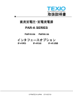
付属品の使用方法
取扱説明書
下記のモデルには次のような付属品が同梱されています。
IF-41GU,IF-41USB,IF-50GP,IF-50USB
1. FG(フレームグランド) 接続用 Y 型端子付きリード線
インタフェースユニット
IF-41GU IF-41USB IF-41RS
IF-50GP IF-50USB
©PRINTED IN JAPAN B71-0009-00
この取扱説明書は、当社電源 PW-A および PAR-A 用 IF ユニット(IF-41GU,IF-41USB,IF-41RS)と電子負荷 LW 用 IF ユニット
(IF-50GP,IF-50USB)の取り付け方法について説明します。
IF ユニットを組み込んだ製品の使用法については、製品本体の取扱説明書をご覧ください。
また、IF-41 シリーズと IF-50 シリーズには互換性がないため、電源 PW-A, PAR-A には IF-41 シリーズを、電子負荷 LW には
IF-50 シリーズを組み込んでください。
IF ユニットの取り付け方法
⑥
2. FG-制御ライン GND 接続用コネクタ
PW-A, PAR-A または LW に IF ユニットを使用して、GP-IB または USB でコントロールする際、周辺のノイズや AC ラインのノイ
ズ、または制御機のノイズにより、誤動作を起こす可能性があります。ノイズの影響で製品のコントロールが安定しない場合が
ありましたら、下記の方法でまず付属の Y 型端子付きリード線を取り付けてください。それでも安定しない場合は付属の GND 接
続用コネクタを取り付けた後に、再度コントロールをお試しください。それでも安定しない場合は、当社営業所にご相談ください。
1. FG 接続用 Y 型端子付きリード線
①
インタフェースユニット
②
④
⑦
本ユニットでは GP-IB または USB ケーブルのシールド及び制御機の FG が本体の FG に接続されていません。このリード
線はその部分を接続するためのケーブルです。
①
①
⑥
絶縁シート
③
②
Fig 1
Fig 2
⑤
(1) AC コードが抜けていることを確認してください。
(2) Fig 1 中①のネジ2本を取り外して、②のケースを取り外してください。
(3) 次に、③のネジ2本を取り外して、④のダミーパネルを取り外してください。
注意 ①は刃付き座金付き、③は平ワッシャー付きのネジです。混同しない様お気を付けください。
②のケースを取り外したあと、製品内部に異物が入らないよう注意してください。絶縁シートの隙間から内部に異物が
入った場合、絶対に電源スイッチを ON しないでください。
(4) Fig 2 の⑦部に並んでいるコネクタに IF ユニットのコネクタを慎重に挿入してください。
(5) IF ユニットは Fig 2 の点線⑤に従って背面の金属製パネルの内側に位置するように取付けてください。
ネジは手順 2 で取り外したネジ(平ワッシャーのもの)を使用してください。コネクタのささり具合が不十分ですとネジ穴が合
わないため、ユニットの装着確認後、慎重にネジ穴を合わせてネジを締めてください。
(6) Fig 2 の⑥部を合わせて、カバーをケースに取り付けてください。取り付けるネジは手順 1 で取り外したネジ(刃付き座金
付き)を使用してください。
(7) 組立て後、電源を入れ、表示部に 41rS、または 50GP といったモデル名が点灯すれば組み込み完了です。ソフトバージョン
3.06 以前と 10.00~10.06 の PW-A 電源に IF-41 シリーズを組み込んだ場合、電源投入時の PW-A 電源表示が
40GU/US/rS となります。表示についても本体取扱説明書をご覧ください。
IF ユニットの取り外し方法
IF ユニットを取り外す必要がある場合は、下記方法で十分に注意して取り外してください。
(1) AC コードが抜けていることを確認してください。
(2) カバーを取り外し、背面のオプションボードを固定するネジを外し、Fig 3 の状態にしてください。
(3) Fig 3 の①の部分にマイナスドライバーを入れて、オプションボードを押し上げてください。
注意 接続用のコネクタがしっかり挿入されている為、IF ユニットが損傷しないよう慎重に押し上げてください。
PW-A および PAR-A の場合
③
Fig 4
LW の場合
(1) Fig4 の①の GP-IB 横のネジを大きめのマイナスドライバーで緩め、Y 型端子を挟み込み、固定してください。
注意 IF-41USB,IF-50USB の場合は GP-IB コネクタはありませんがネジは同位置にあります。
(2)もう片側の Y 型端子を PW-A, PAR-A は②の AC インレット固定ネジで、LW は③の FG 用ネジで共締めして固定してください。
その際、Y 型端子リード線が排気を妨げないようにご注意ください。
注意 固定ネジは締めすぎないで下さい。
2. FG-制御ライン GND 接続用コネクタのコネクタ
①
本ユニットの制御信号の GND は他電位から絶縁されてい
ます。このコネクタはその信号 GND を本体の FG に接続す
るコネクタです。
(1) IF ユニットを取り外します。
(2) Fig 5 の①のコネクタに本コネクタを差しこみます。
(3) IF ユニット取り付け方法を参照し、再度組み立ててください。
Fig 5
USB ドライバーの入手について
①
Fig 3
USB ドライバーが必要な場合、下記の当社ホームページからダウンロード出来ますのでご利用ください。
また郵送のサービスも行っておりますので、当社営業所までお問い合わせください。
http://www.texio.co.jp
R
Usage of Accessories
INSTRUCTION MANUAL
The following products are supplied with the accessories shown below:
IF-41GU, IF-41USB, IF-50GP, and IF-50USB
1. Lead wire with Y terminals for connecting the FG (frame ground) terminal.
INTERFACE UNITS
IF-41GU IF-41USB IF-41RS
IF-50GP IF-50USB
2.
Connector for connecting the FG terminal and the control line GND
©PRINTED IN JAPAN B71-0009-00
This instruction manual mainly describes how to install the interface units, IF-41GU, IF-41USB, IF-41RS (PW-A or
PAR-A) and IF-50GP, IF-50USB (for LW). For the usage of the products with the interface unit built in, refer to the
instruction manual of the each model.
As there is no compatibility between IF-41 and IF-50 series, each one should be mounted in the specified series, PW-A
and PAR-A or LW.
⑥
Installation of the optional board
①
④
1. Lead wire with Y terminals shown in 1
In this unit, the shield of the GP-IB or USB cable and the FG of the controller are not connected with the FG of the
main body. This lead wire is used to connect these points.
Interface unit
②
In GP-IB or USB control of the PW-A, PAR-A or LW using an IF unit, peripheral noises, AC line noises or controller
noises may cause malfunctioning.
Connect the lead wire supplied with the product as shown below, if control is unstable due to noises. Plug the
connector and then try to carry out control, if control is still unstable even after connecting the lead wire. If control is still
unstable, contact the nearest our distributor.
①
①
⑦
⑥
③
Insulation sheet
Fig. 1
Fig. 2
⑤
(1) Make sure that the AC cable is disconnected.
(2) Remove two screws ① shown in Fig. 1. Detach the case ②.
(3) Remove two screws ③. Detach the dummy panel ④.
NOTE : The screws ① are with toothed lock washers. The screws ③ are with flat washers. Be careful not
to mistake them.
NOTE : Be careful not to let foreign matters into the Product unit after detaching the case ②. Never throw the
power switch if foreign matters are put into the PW-A power supply unit through the clearance of the
insulation sheet.
(4) Plug the connector of the optional board with the connector on the side of ⑦ shown in Fig. 2.
(5) Install the optional board inside the rear metallic panel as shown by dotted line ⑤ in Fig. 2. Use the screws (with
flat washers) removed in (2). If the connector is not plugged sufficiently, the screw holes will not be in position.
Make sure that the unit is installed properly and drive the screws.
(6) Fit portions ⑥ shown in Fig. 2 and attach the cover onto the case using the screws (with toothed lock washers)
removed in (1).
(7) After installing the unit, turn on the power supply unit. It is installed properly if a model name lights up on the display
portion. PW-A power supply indication will be 40GU/US/rS while incorporating IF-41 series into the PW-A power supply
for software version 3.06 and before 10.00 to 10.06. For the display, refer to the instruction manual of the power supply
unit. a model name lights up
Follow the instructions below when detaching the optional board:
(1) Make sure that the AC cable is disconnected.
(2) Detach the cover, remove the optional board set screws from the rear panel, and make the condition shown in Fig. 3.
(3) Insert a flathead screwdriver into ① shown in Fig. 3 and press up the optional board.
<Precaution> The connector is plugged firmly. Press up the optional board with great care not to damage it.
②
PW-A and PAR-A
Fig
4
③
LW
(1) Loosen the screw ① on the side of the GP-IB connector shown in Fig. 4 with a large-size flathead screwdriver.
Insert the Y terminal, and fix it.
NOTE: The IF-41USB or IF-50USB has this screw at the same position, though it has no GP-IB connector.
(2) Fix the other Y terminal with the AC inlet fixing screw ② (PW-A, PAR-A) or the FG screw ③ (LW).
Be careful not to impede ventilation with the lead wire when connecting it.
NOTE: Please do not tighten a fixed screw too much.
2. Connector shown in 2
The control signal GND line of this unit is isolated from other
potentials. This connector is used to connect the signal GND
with the FG of the main body.
(1) Dismount the IF unit.
(2) Plug this connector into the connector ① shown in Fig. 5.
(3) Undo the IF unit.
Acquisition of USB Driver
You may download the USB driver from the homepage shown below if you need it.
Contact the nearest our distributor.
http://www.texio.co.jp
①
Fig. 3
①
Fig 5