1
®
Badger Meter Europa GmbH
LM OG / LM OG-A / LM OG-S /
LM OG-Oily / LM OG-P
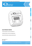
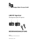
Zählerbaureihe mit elektronischem Zählwerk für Schmieröl eichfähig und nicht eichfähig
Oval gear meters with electronic register for lubricants approved and non approved
Compteurs électroniques pour le mesurage de lubrifiants homologués et non homologués.
MONTAGE- UND
BEDIENUNGSANLEITUNG
INSTRUCTIONS FOR
USE AND MAINTENANCE
MANUEL D´INSTALLATION
Version LM OG/LM OG-A/LM OG-S/LM OG-Oily/LM OG-P 03/09
Inhaltsverzeichnis / Content / Index
Inhaltsverzeichnis
1.
2.
3.
4.
4.1
4.2
4.3
4.4
4.5
4.6
4.7
5.
5.1
5.2
5.3
6.
7.
8.
9.
10.
Allgemeines
Hinweis zur Inbetriebnahme
Elektronisches Anzeigewerk mit LCD-Anzeige
Hinweise für den Betrieb
Batterie
Rückstellung – RESET
Unterbrechung des Dosiervorganges
Funktionsüberwachung
Summierzählwerk
Fehlerüberwachung bei eichfähigem Zähler
Zählermontage LM OG
Programmierung und Bedienung
LM OG / LM OG-A
LM OG-S / LM OG-Oily
LM OG-P
Technische Daten
Anschlussdiagramm LM OG-TAE(R) 200 und LM OG-T 100
Zulassungen
Herstellererklärung
Garantieerklärung
Contents
1.
2.
3.
4.
4.1
4.2
4.3
4.4
4.5
4.6
4.7
5.
5.1
5.2
5.3
General
Before putting into operation
Electronic register with LC-display
Details of unit operation
Battery
RESET
Interruption of batch process
Functional control
Totalizer
Monitoring of false pulses
Installation procedure LM OG
Programming and use
LM OG / LM OG-A
LM OG-S / LM OG-Oily
LM OG-P
Seite
1
1
1
2
2
2
2
3
3
3
4
5
5
8
9
22
23
24
25
74
Page
26
26
26
27
27
27
27
27
28
28
29
29
29
32
33
Inhaltsverzeichnis / Content / Index
6.
7.
8.
9.
10.
Technical data
Wiring diagram LM OG-TAE(R) 200 and LM OG-T 100
Approvals
Manufacturer's declaration
Warranty
Index
1.
2.
3.
4.
4.1
4.2
4.3
4.4
4.5
4.6
4.7
5.
5.1
5.2
5.3
6.
7.
8.
9.
10.
46
47
48
48
74
Page
Avant la mise en service
Généralités
Cadran électronique avec affichage à cristaux liqudes
Service
Batterie
Remise à zéro – RESET
Interruption comptage
Contrôle de fonctions
Totalisateur
Contrôle erreur sur compteurs homologués
Montage
Programmation et utilisation
LM OG / LM OG-A
LM OG-S / LM OG-Oily
LM OG-P
Données techniques
Installation électrique LM OG-TAE(R) 200 et LM OG-T 100
Approbations
Déclaration du fabriquant
Garantie
50
50
50
51
51
51
51
52
52
52
53
53
53
56
57
70
71
72
73
74
Hinweis zur Inbetriebnahme
1.
Seite 1/74
Hinweis zur Inbetriebnahme
Prüfen, ob die technischen Daten der Anlage mit denen des Schmierölzählers übereinstimmen, z.B.
Anschlüsse, Druck, Durchfluss und Medium.
Nachdem das Gerät installiert ist, muss sichergestellt werden, dass keine Luft, Druckstösse oder
Fremdkörper das Gerät beschädigen können.
Alle Anschlüsse auf Leckage prüfen.
Es wird empfohlen, dass nach der Installation mehrere Zapfungen in einen Eichbehälter gemacht
werden. Sollten sich durch den Einsatz verschiedener Ölviskositäten Abweichungen der Fehlergrenze
ergeben, so kann dies sofort vor Ort korrigiert werden. Somit entfällt ein Ausbau oder Austausch des
Geräts.
Bei vorgeprüften Geräten können die Korrekturen von Installateuren oder auch Eichbeamten durchgeführt werden.
2.
Allgemeines
Der Aufbau des Messwerks als Ovalradzähler ist bei allen Ausführungen der Schmierölzähler-Gerätereihe gleich. Das Messwerk besteht aus Messkammer und Ovalrad. Messwerk und Gehäuse bilden
den Grundzähler.
Die Baureihe OG hat ein elektronisches Anzeigewerk. Dieses Anzeigewerk wird stopfbuchsenfrei über
einen 4-poligen Magneten angetrieben und ist hermetisch gegen das Messwerk abgedichtet.
3.
Elektronisches Anzeigewerk mit LCD-Anzeige
Das elektronische Zählwerk erfasst die Kolbendrehungen über zwei versetzt angeordnete Reedschalter und berechnet daraus das gemessene Volumen in technischen Einheiten
Das Messergebnis wird auf einem Display angezeigt. Die Gesamtmenge wird ebenfalls registriert und
kann auf Knopfdruck abgerufen werden.
Datenerfassung und Auswertung werden elektronisch überwacht; eventuell auftretende Fehler
werden angezeigt.
Das elektronische Zählwerk benötigt ein zweiphasiges Eingangssignal, das auf Phasenfehler überwacht wird. Das Zählwerk führt vor jedem RESET einen automatischen Selbsttest durch.
OG Service- und Bedienungsanleitung / Manual of installation /
Manuel d´installation LM OG/LM OG-A/LM OG-S/LM OG-Oily/LM OG-P 03/09
Elektronische Anzeigewerk mit LC-Anzeige
Seite 2/74
Das LCD-Anzeigewerk ist über 3 Schrauben mit dem Grundzähler verbunden. Bei den eichfähigen
Ausführungen ist das Anzeigewerk mit einer Plombe gesichert. Es wird bei Servicearbeiten nur als
geschlossenes Modul getauscht. Werkseitig ist ein Kalibrierfaktor einprogrammiert, der auf einem
hydraulischen Prüfstand ermittelt wurde. Das Zählwerksgehäuse besteht aus schlagfestem, glasfaserverstärktem Kunststoff.
Der Elektronikteil ist schockgesichert und gegen Öleintritt abgedichtet. Es entspricht den RFI und EMI
Schocktestbedingungen.
Nach Montage auf dem Grundzähler ist die Elektronik gegen elektromagnetische Störeinflüsse abgeschirmt und wird mit einer Lithium-Batterie versorgt.
Die LCD-Anzeige ist 5-stellig mit einer Auflösung von 0,002 Liter für den eichfähigen Einsatz.
Für den Betrieb genügen zwei Foliendrucktasten: RESET (Rückstellung) und TOTAL (Gesamtmenge).
4.
Hinweise für den Betrieb
4.1
Batterie
Die Batterie ist austauschbar. Der Austausch muss von Fachpersonal durchgeführt werden, da gleichzeitig der Kalibrierfaktor neu einprogrammiert werden muss. Vor Batterieentleerung erscheint ein
Batteriesymbol zum Batteriewechsel.
Batterie-Typ: Lithium CF 1/2 AA
4.2
Rückstellung – RESET
Die Anzeige des Dosierzählerspeichers kann durch Betätigen der RESET-Taste auf NULL gesetzt
werden. Eine Rückstellung während eines laufenden Arbeitsvorgangs ist nicht möglich. Der Summierzählerspeicher ist nur über die interne Programmierung rückstellbar.
4.3
Unterbrechung des Dosiervorganges
Durch Entsperren bzw. Freigeben des Betätigungshebels wird der Dosiervorgang unterbrochen. Bei
erneutem Betätigen wird der Dosiervorgang an der Unterbrechungsstelle fortgesetzt, wenn nicht
vorher die RESET-Taste gedrückt wird. Die Anzeige bleibt während der Dauer der Unterbrechung
stehen. Wird der Dosiervorgang extern vom Schmierölzähler, z.B. durch Ausfall der Förderpumpe,
unterbrochen, geschieht dasselbe wie bei der normalen Unterbrechung.
OG Service- und Bedienungsanleitung / Manual of installation /
Manuel d´installation LM OG/LM OG-A/LM OG-S/LM OG-Oily/LM OG-P 03/09
Hinweise für den Betrieb
4.4
Seite 3/74
Funktionsüberwachung
Der RESET-Befehl löst automatisch einen Selbsttest des Zählwerks aus. Das LCD zeigt alle Anzeigesegmente "8“ an. Volumenimpulse, die während der Selbsttest-Phase einlaufen, werden registriert
und ausgewertet. Alle anderen gespeicherten Werte wie Masseinheit und Korrekturfaktor werden
geprüft. Erst, wenn die Werte übereinstimmen, wird eine normale Messung durchgeführt. Falls ein
oder mehrere Werte nicht übereinstimmen, wird dies durch eine Reihe von Strichen
(- - - -)
angezeigt und die Zählfunktion stillgelegt.
Das gemessene Volumen bzw. alle Reedschalter-Messimpulse werden in jedem Fall ausgewertet und
zu dem zuletzt angezeigten Dosiervolumen hinzuaddiert, solange nicht durch Drücken der RESET-Taste
ein neuer Dosiervorgang ausgelöst wird.
4.5
Summierzählwerk
Die Betätigung der TOTAL-Taste bewirkt die Anzeige des Summierspeicherwertes, solange die Taste
gedrückt bleibt, aber nur, wenn keine Volumenimpulse registriert werden (siehe Kalibrier- oder
Korrekturfaktor).
Der werkseitig programmierte Korrekturfaktor ergibt sich bei der Genauigkeitsprüfung des Grundzählers mit aufgesetztem elektronischem Anzeigewerk.
Beispiel:
Abgegebene Menge: 4,2 Liter
Angezeigte Menge: 4,0 Liter
Korrekturfaktor k = 4,2/4,0 = 1,05
Werden die TOTAL und die RESET-Taste in dieser Reihenfolge gleichzeitig betätigt, wird der einprogrammierte Korrekturfaktor solange angezeigt, wie beide Tasten gedrückt bleiben.
Sobald Volumensignale eingehen, werden die Tastaturbefehle ignoriert!
4.6
Fehlerüberwachung bei eichfähigem Zähler
Während der Messung überwacht der MIKROPROZESSOR die Phasenlage der beiden Reedschalter
(30° bis 150° Phasenverschiebung).
OG Service- und Bedienungsanleitung / Manual of installation /
Manuel d´installation LM OG/LM OG-A/LM OG-S/LM OG-Oily/LM OG-P 03/09
Hinweise für den Betrieb
Seite 4/74
Pulsfolgefehler:
Wenn nach einem RESET mehr als zwei Phasenfehler registriert werden, blinkt die LCD-Anzeige mit 1
Hz bzw. im 1-Sekunden-Takt, und signalisiert so, dass die erlaubte Fehlergrenze überschritten wurde.
Fehlimpulse und Warnanzeige werden durch Ausführen eines RESET-Befehls gelöscht. Kann das
Blinken nicht gelöscht werden, liegt ein Defekt vor und das Zählwerk muss ausgetauscht werden.
Das Blinken kann z.B. auch durch eine kurzzeitige Rückwärtsströmung beim Anfahren oder bei
schlecht entlüfteter Ölleitung auftreten (Druckstösse). Dies kann durch Einbau eines geeigneten Rückflussverhinderers ausgeschlossen werden.
Fehler in den gespeicherten Variablen:
(Korrekturfaktor, Masseinheit)
Diese Fehler werden durch eine Reihe von Strichen (- - - -) angezeigt und können nicht durch den
Kunden beseitigt werden. Das Zählwerk muss ausgetauscht, werkseitig überprüft und ggf.
instandgesetzt werden.
4.7
Zählermontage LM OG
Bitte Folgendes bei der Zählermontage beachten:
Die Zählerbaureihe LM OG ist eingangsseitig mit einem 1/2" BSP Innengewinde versehen. Um eine
sichere und leckfreie Verbindung vom Zähler zum Hydraulikschlauch zu erreichen, muss das Schlauchende ein 1/2" BSP Aussengewinde haben.
Vor dem Einschrauben empfehlen wir, wie folgt vorzugehen:
1.
Beide Gewinde fettfrei machen.
2.
1/2" Aussengewinde am Hydraulikschlauch mit Flüssigdichtung (z.B. Eurolock 310100 oder
equivalente Dichtmittel anderer Hersteller) einstreichen. Dabei ist zu beachten, dass kein Dichtmittel in den Zähler gelangen kann.
3.
Beide Teile zusammenschrauben,
Schraubenverbindung nicht zu fest anziehen, dies könnte das Drehgelenk des Zählers beschädigen.
4.
Unbedingt die Anweisung des Dichtmittelherstellers beachten.
5.
Die Zählermontage sollte nur von autorisiertem Personal durchgeführt werden.
OG Service- und Bedienungsanleitung / Manual of installation /
Manuel d´installation LM OG/LM OG-A/LM OG-S/LM OG-Oily/LM OG-P 03/09
Programmierung und Bedienung
Seite 5/74
Die richtige Auswahl der Komponenten, sowie ihre vorschriftsmässige Montage und Inbetriebnahme
obliegt der Verantwortung des Anwenders.
5.
Programmierung und Bedienung
5.1
LM OG / LM OG-A
Die Masseinheit und der Korrekturfaktor können programmiert werden.
Zum Programmieren wird ein Taster auf der Unterseite des elektronischen Zählwerks betätigt und
während des gesamten Programmiervorgangs eingeschaltet gehalten. Der Programmiertaster ist nur
zugänglich, nachdem das elektronische Zählwerk von der Messkammer abgenommen wurde. Dazu
muss bei der eichfähigen Ausführung eine plombierte Schraube gelöst werden, damit nur befugte
Personen diesen Eingriff vornehmen können.
Programmierablauf:
a)
Durch Betätigen des Programmierschalters werden die aktuellen Zustände von Korrekturfaktor
und Masseinheit auf dem Display angezeigt. Vor dem ersten Programmieren werden dargestellt:
- Korrekturfaktor = 0,0000
- Masseinheit L
Der Korrekturfaktor kann im Bereich von 0,0000 bis 9,9999 programmiert werden. Das Komma
steht immer hinter der ersten Stelle. Dieses Komma wird bei der Masseinheit Liter als Komma
(,) und bei allen anderen Masseinheiten als Punkt (.) dargestellt.
b)
Das Zeichen für die Masseinheit blinkt sofort nach Betätigen des Programmiertasters. Alle
anderen Zeichen werden konstant angezeigt. Das Blinken macht den veränderbaren Wert
kenntlich. Jeder Tastendruck auf RESET schaltet nun die Masseinheit weiter, und zwar in der
Reihenfolge (QT) – GAL – L – PT.
Nach Auswahl der benötigten Masseinheit wird dieser Programmteil durch Betätigen der
TOTAL-Taste verlassen. Gleichzeitig wird die so gewählte Masseinheit als aktueller Wert vorgemerkt.
c)
Der zuletzt geschaltete Wert wird durch Betätigen der TOTAL-Taste im Programm als aktueller
Wert vorgemerkt.
d)
Jede Betätigung der RESET-Taste schaltet den Wert von "0“ bis "9" um jeweils 1 weiter. Der
gewünschte Wert wird durch Bestätigen der TOTAL-Taste im Programm vorgemerkt.
OG Service- und Bedienungsanleitung / Manual of installation /
Manuel d´installation LM OG/LM OG-A/LM OG-S/LM OG-Oily/LM OG-P 03/09
Programmierung und Bedienung
Seite 6/74
e)
Das Abschliessen der Programmierung der ersten Stelle des Korrekturfaktors durch Betätigen
der TOTAL-Taste schaltet auf die Programmierung der zweiten Stelle des Korrekturfaktors um.
Sie blinkt im 0,3 s-Takt. Jede Betätigung der RESET-Taste schaltet den Wert von "0" bis "9"
um jeweils 1 weiter. Der gewünschte Wert wird durch Bestätigen der TOTAL-Taste im
Programm vorgemerkt.
f)
Der in Abschnitt e) beschriebene Vorgang zur Programmierung der zweiten Stelle des Korrekturfaktors wird in gleicher Weise zur Programmierung der restlichen 3 Stellen durchgeführt.
g)
Ist der geforderte Wert bereits eingestellt gewesen, kann durch Betätigen der TOTAL-Taste
unmittelbar auf die nächste Stelle übergegangen werden. Der angezeigte, blinkende Wert wird
dann so im Programm vorgemerkt.
h)
Wird die Programmierung an einer beliebigen Stelle durch die Freigabe des Programmiertasters
unterbrochen, dann werden die bis dahin eingegebenen neuen Werte und die ggf. nicht veränderten alten Werte als aktueller Programmierstand übernommen. Die LCD-Anzeige blinkt dreimal
und zeigt dabei die nunmehr gespeicherten Programmwerte zur Bestätigung an.
i)
Mit der Speicherung des Programmwertes gemäss Abschnitt h) multipliziert der Mikroprozessor
den damit festgelegten Korrekturwert mit dem durch Programmierpunkt b) festgelegten
Quellenwert. Der so gewonnene Faktor stellt das korrekte Volumeninkrement dar, das einem
Eingangsmessimpuls entspricht. Dieser Wert und die Masseinheit werden sicherheitshalber
einfach redundant gespeichert.
j)
Der Inhalt des Summierzählspeichers bleibt auch bei einer Umprogrammierung erhalten, solange
die Masseinheit nicht geändert wird. Wird die Programmierung in Punkt h) mit einer neuen
Masseinheit abgeschlossen, erfolgt automatisch die Rücksetzung des Summierzählspeichers auf
Null.
Nach Freigabe des Programmiertasters schaltet der Mikroprozessor alle Funktionen, einschliesslich LCD-Anzeige, bis auf die Datenspeicherung, ab. Dieser Zustand bleibt solange erhalten, bis
entweder der RESET oder der TOTAL-Befehl gegeben wird. Zum erneuten Abschalten muss die
Programmiertaste erneut betätigt werden.
Der Programmierschalter selbst ist ausser Betrieb, wenn der Mikroprozessor in der vorgenannten Weise abgeschaltet ist.
OG Service- und Bedienungsanleitung / Manual of installation /
Manuel d´installation LM OG/LM OG-A/LM OG-S/LM OG-Oily/LM OG-P 03/09
Programmierung und Bedienung
Setie 7/74
Beispiel – Korrektur der Messgenauigkeit
Tatsächlich abgegebene Menge: 1,6 l
Angezeigt Menge: 1,52 l
Korrekturfaktor k = 1,6/1,52 = 1,0526
a)
Anzeige des bisher programmierten Korrekturfaktors durch Drücken und Halten der TOTALTaste und gleichzeitiges Drücken der RESET-Taste. Beispiel: 0,9950
b)
Errechnen des neu zu programmierenden Korrekturfaktors:
0,9950 x 1,0526 = 1,0473
c)
Lösen der 3 Zählwerksbefestigungsschrauben und Abnehmen des Zählwerks.
d)
Programmiertaste drücken und bis zum Ende des Programmiervorganges halten.
e)
Im Display werden die folgenden Informationen angezeigt:
- augenblicklicher Korrekturfaktor
- Masseinheit (blinkend)
- Drehrichtungspfeile
f)
Die TOTAL-Taste solange drücken, bis die erste zu ändernde Zahl blinkt – in diesem Fall die
0.
g)
Die RESET-Taste so oft drücken, bis der gewünschte Wert erreicht ist – in diesem Fall
einmal, um die 1 zu erreichen.
h)
TOTAL-Taste so lange drücken, bis die nächste zu ändernde Zahl blinkt – in diesem Fall die
erste 9.
i)
Die RESET-Taste so oft drücken, bis der gewünschte Wert erreicht ist – in diesem Fall
einmal, um die 0 zu erreichen.
j)
TOTAL-Taste so lange drücken, bis die nächste zu ändernde Zahl blinkt – in diesem Fall die
zweite 9.
k)
Die RESET-Taste so oft drücken, bis der gewünschte Wert erreicht ist – in diesem Fall
fünfmal, um die 4 zu erreichen.
l)
TOTAL-Taste so lange drücken, bis die nächste zu ändernde Zahl blinkt – in diesem Fall die
5.
OG Service- und Bedienungsanleitung / Manual of installation /
Manuel d´installation LM OG/LM OG-A/LM OG-S/LM OG-Oily/LM OG-P 03/09
Programmierung und Bedienung
Seite 8/74
m) Die RESET-Taste so oft drücken, bis der gewünschte Wert erreicht ist – in diesem Fall
zweimal, um die 7 zu erreichen.
n)
Die TOTAL-Taste so lange drücken, bis die nächste zu ändernde Zahl blinkt – in diesem Fall
die 0.
o)
Die RESET-Taste so oft drücken, bis der gewünschte Wert erreicht ist – in diesem Fall
dreimal, um die 3 zu erreichen.
p)
Programmiertaste freigeben, das Display blinkt 3 Mal und zeigt dabei die nunmehr
gespeicherten Programmwerte an.
q)
Das Zählwerk wieder auf den Grundzähler montieren.
Nach dem Programmieren muss zur LCD-Aktivierung die RESET-Taste gedrückt werden.
5.2
LM OG-S / LM OG-Oily
1.
Zuerst die rechte Taste 3 mal drücken und dann innerhalb von 500 mS die linke Taste 3 mal
drücken, um den Korrekturfaktor einzugeben.
2.
Der Korrekturfaktor wird angezeigt.
3.
Zum Zurückscrollen die rechte Taste drücken. Zum Vorscrollen die linke Taste drücken und den
neu errechneten Korrekturfaktor eingeben
4.
Die linke und rechte Taste gleichzeitig 2 Sekunden gedrückt halten, um die verschiedenen
Masseinheiten Liter, Quart, Pint, Gallon aufzurufen.
5.
Das Display zeigt nun eine Ziffer, um die gewünschte Masseinheit zu wählen.
"0" für Liter; "1" für Quart; "2" für Pint; "3" für Gallon.
6.
Die rechte Taste drücken, um 0, 1, 2, 3 zurückzuscrollen.
Die linke Taste drücken, um 3, 2, 1, 0 vorzuscrollen.
7.
Die linke und rechte Taste gleichzeitig 3 Sekunden gedrückt halten, um die Daten zu speichern
und das Menü zu verlassen.
OG Service- und Bedienungsanleitung / Manual of installation /
Manuel d´installation LM OG/LM OG-A/LM OG-S/LM OG-Oily/LM OG-P 03/09
Programmierung und Bedienung
5.3
Seite 9/74
LM OG-P
Display und Keypad
Stelle der Programmiertaste
Funktion der Keypad-Tasten:
10 / Historie
Mit dieser Taste wird die "Programmierung der Vorwahlmenge" (in 10 Liter Schritten)
eingestellt.
Im Betriebsmodus zeigt diese Taste die letzten fünf Abgabemengen an.
1
Mit dieser Taste wird die "Programmierung der Vorwahlmenge" (in 1 Liter Schritten)
eingestellt.
0.1 / Durchfluss
Mit dieser Taste wird die "Programmierung der Vorwahlmenge" (in 0,1 Liter Schritten)
eingestellt.
Im Betriebsmodus wird mit dieser Taste der Durchfluss während einer Abgabe angezeigt.
TOTAL
Mit dieser Taste gehen Sie schrittweise durch die Programmierung. Im Betriebsmodus
wird mit dieser Taste die Gesamtmenge angezeigt. Diese ist nicht rückstellbar, alle
Abgaben sind aufsummiert.
AUTO
Diese Taste ermöglicht den Zugang und das Verlassen des Modus "Programmierung der
Vorwahlmenge".
RESET
In allen Programmiermoden dient die Reset-Taste zum schrittweisen Weitertasten.
Im Betriebsmodus wird mit dieser Taste die letzte abgegebene Menge gelöscht.
Im Modus "Totalisator" wird mit der Reset-Taste die Nulleinstellung gelöscht.
OG Service- und Bedienungsanleitung / Manual of installation /
Manuel d´installation LM OG/LM OG-A/LM OG-S/LM OG-Oily/LM OG-P 03/09
Programmierung und Bedienung
Seite 10/74
ESCAPE
Notabschaltung.
PROGRAMM
Die Programmiertaste ist auf der Unterseite des Zählers.
Durch Drücken mittels eines Stifts kann die Programmierung von Masseinheit und
Korrekturfaktor durchgeführt werden. Bei eichfähigen Geräten ist der Schalter verplombt.
Programmierung des Skalierfaktors und der Masseinheit:
Der Zähler wird werkseitig in Liter programmiert. Eine neue Programmierung ist nicht erforderlich, es
sei denn, die Masseinheit oder das Medium muss angepasst werden.
-
RESET-Taste drücken, um das Display zu aktivieren.
Programmiertaste drücken und 2 Sekunden festhalten, um den Programmiermodus abzurufen.
Das Display blinkt kurz und zeigt dann den Skalierfaktor und die Masseinheit an.
1.0000 L
Display am Anfang der Programmierung
Programmierung der Masseinheiten:
Vier Masseinheiten stehen zur Verfügung: Liter (L), Quarts (QT), Gallonen (GAL) und Pint (PNT).
Der Zähler wird werkseitig in Liter programmiert. Beim Anschalten blinkt die "L"-Einheit.
-
Mit der TOTAL-Taste wählen Sie eine der vier Masseinheiten (L, QT, GAL, PNT).
RESET-Taste drücken, um die gewünschte Masseinheit am Display zu bestätigen. Die
Masseinheit hört auf zu blinken und die erste Ziffer des Skalierfaktors fängt an zu blinken.
NB: Wenn Sie die Masseinheit "L" ausgewählt haben, fängt der Dezimalpunkt an zu blinken. Sie
haben nun die Möglichkeit, den Dezimalpunkt durch einen Punkt oder ein Komma zu ersetzen. Um
dies durchzuführen, drücken Sie bitte die TOTAL-Taste. Drücken Sie die RESET-Taste, um auf den
Skalierfaktor zu wechseln.
OG Service- und Bedienungsanleitung / Manual of installation /
Manuel d´installation LM OG/LM OG-A/LM OG-S/LM OG-Oily/LM OG-P 03/09
Programmierung und Bedienung
Seite 11/74
ACHTUNG
Wenn Sie die Masseinheit von metrisch auf englisch, oder von englisch auf metrisch wechseln,
werden der Totalisator, die Nulleinstellung und der Speicher gelöscht.
Rekalibrierung:
Die Einstellung der Zählergenauigkeit erfolgt über den Skalierfaktor. Der Skalierfaktor wird werkseitig
für Öl eingestellt.
Rekalibrierung des Skalierfaktors:
Um den Skalierfaktor einzustellen, gehen Sie bitte wie folgt vor:
Lassen Sie eine vorgegebene Ölmenge durch den Zähler fliessen (z.B. 5,00 Liter). Wenn der Zähler
programmiert ist, um in Liter zu messen und der Zähler die gesamte Menge abgibt, zeigt aber nur
4,670 Liter am Display an, dann soll der Skalierfaktor neu kalibriert werden. Dividieren Sie die
Abgabemenge (5,00) durch die angezeigte Menge (4,670), um den Korrekturfaktor zu errechnen
(1.07).
NB: Der Zähler wurde werkseitig kalibriert, der Kalibrierfaktor steht auf der Zählerunterseite.
Änderung des Kalibrierfaktors:
-
TOTAL-Taste zuerst drücken und festhalten, dann die AUTO-Taste, um den programmierten
Skalierfaktor zu sichten.
Beispiel: 1.0123
Errechnen des neuen Kalibrierfaktors:
Beispiel: 1.0123 (einprogrammierter Skalierfaktor) x 1.05 (Korrekturfaktor) = 1.0629 (neuer
Skalierfaktor).
Um den Skalierfaktor zu ändern, drücken Sie die Programmiertaste, um den Programmiermodus
abzurufen, und die RESET-Taste, um in die verschiedenen Einheitsmodi zu gelangen.
a) Die erste Ziffer des Skalierfaktors blinkt.
b) TOTAL-Taste drücken, um durch die Ziffer zu skalieren.
c) RESET-Taste drücken, um bis zur gewünschten Ziffer zu gelangen.
d) Wiederholen Sie Punkt 2 und 3 für alle fünf Ziffern des Skalierfaktors.
NB: Sie können für alle Ziffern (mit der Ausnahme von der ersten) zwischen 0 und 9 wählen. Für die
erste Ziffer können Sie nur zwischen 0 und 1 wählen.
e) Bestätigen Sie den neu programmierten Skalierfaktor mit RESET. Der Impulsverzögerungsfaktor
wird angezeigt.
OG Service- und Bedienungsanleitung / Manual of installation /
Manuel d´installation LM OG/LM OG-A/LM OG-S/LM OG-Oily/LM OG-P 03/09
Programmierung und Bedienung
Seite 12/74
Einstellung des Impulsverzögerungsfaktors:
Der Impulsverzögerungsfaktor korrigiert die schnellen Durchflussraten, indem er das Ventil zwischen 1
und 5 Impulsen früher schliesst. Der werkseitig programmierte Impulsverzögerungsfaktor ist 0.
Drücken Sie RESET zur Änderung.
Nachstehende Anzeige erscheint auf dem Display:
PS - O
a)
b)
c)
d)
Nach den zwei Buchstaben "PS" blinkt eine Null. Die Null ist die Grundeinstellung des
Impulsverzögerungsfaktors.
Die gewünschte Einstellung (zwischen 0 und 5) mit der TOTAL-Taste auswählen.
Mit RESET bestätigen. Das Display kehrt automatisch zum Skalierfaktor zurück.
Wenn Sie mit der Programmierung dieser Optionen fertig sind, drücken und halten Sie die
Programmiertaste solange fest, bis das Display dreimal blinkt und ausschaltet.
Bedienung: Freie Abgabe
a)
Wählen Sie Option "O" im Modus "Programmierung der Vorwahlmenge" (siehe 3.2), um die
freie Abgabe zu programmieren.
0.00 L
b)
c)
Drücken Sie den Hebel am Handgriff, um die Abgabe zu starten.
Wenn die gewünschte Menge abgegeben wurde, lassen Sie den Hebel wieder los, um die
Abgabe zu beenden.
Drücken Sie RESET, um die Nulleinstellung durchzuführen.
Programmierung der Vorwahlmenge:
a)
AUTO-Taste drücken und festhalten, um in den Modus "Programmierung der Vorwahlmenge"
zu gelangen.
OG Service- und Bedienungsanleitung / Manual of installation /
Manuel d´installation LM OG/LM OG-A/LM OG-S/LM OG-Oily/LM OG-P 03/09
Programmierung und Bedienung
Seite 13/74
Nachstehende Anzeige erscheint am Display:
0.00 L
AUTO 1:
0.0 Ç
Auto Modus, Option 1
b)
Der Zähler ist nun programmierbereit. Die Ziffer "1" vor dem Doppelpunkt blinkt. Dies ist das
Ikon "Option". Option "O" ist freie Abgabe. Optionen "1" bis "5" sind für automatische Vorwahlprogrammierungen. Es können verschiedene Vorwahlmengen in jeder Option gespeichert
werden. Option "6" ist für Vorwahlmengen grösser als 99.9 Einheiten. Diese Option funktioniert
nur zwischen 100 und 999 Einheiten. Drücken Sie die TOTAL-Taste, um die verschiedenen
Optionen anzuzeigen.
6.70 L
AUTO
3:
6.7 È
Auto Modus, Option 3
c)
Wenn die gewünschte Option angezeigt wird, drücken Sie die Tasten
, um die Vorwahlmenge zu ändern.
,
- Drücken Sie die Taste 10, um die 10 l Sequenz zu ändern.
- Drücken Sie die Taste 1, um die 1 l Sequenz zu ändern.
- Drücken Sie die Taste 0.1, um die 0,1 l Sequenz zu ändern.
z.B. Vorwahl 42,7 l
Drücken Sie:
4 x 10
2x1
7 x 0,1
NB: Bei Programmierung in Option "6" multiplizieren sich die Werte um Faktor 10.
6 70 L
AUTO
6:
6 70 È
Auto Modus, Option 6
OG Service- und Bedienungsanleitung / Manual of installation /
Manuel d´installation LM OG/LM OG-A/LM OG-S/LM OG-Oily/LM OG-P 03/09
und
Programmierung und Bedienung
d)
Seite 14/74
Drücken Sie die RESET-Taste und die Aufwärts-/Abwärtspfeile blinken. Drücken Sie TOTAL, um
zwischen dem Aufwärts- und Abwärtszähler zu wählen. Drücken Sie auf RESET, um Ihre Wahl
zu bestätigen.
NB: Beim Aufwärtszählen wird von 0 bis zur gewünschten Vorwahlmenge gezählt. Beim
Abwärtszählen wird von der gewünschten Vorwahlmenge bis zu 0 gezählt.
e)
Wenn die gewünschte Vorwahlmenge programmiert wurde, verlassen Sie diese Option mit der
AUTO-Taste. Das Display blinkt. Sollte sich der Zähler im abwärtszählenden Modus befinden, so
wird die angezeigte Vorwahlmenge gezapft. Sollte sich der Zähler im aufwärtszählenden Modus
befinden, erscheint eine Null auf dem Display und zählt bis zum Erreichen der Vorwahlmenge.
6.70 L
6.7 È
AUTO
Abwärtszählender Modus
0.00 L
AUTO
6.7 Ç
Aufwärtszählender Modus
Vorwahlmodus (Auto):
a)
Programmieren Sie den Zähler wie im Punkt 3.2 "Programmierung der Vorwahlmenge",
Optionen 1 bis 6 beschrieben.
b)
Ziehen Sie den Hebel am Handgriff, um die Abgabe zu starten. Die Abgabe wird automatisch beendet, sobald die gewünschte Menge erreicht ist.
c)
Drücken Sie RESET am Ende des Vorgangs. Der Zähler ist nun bereit für die nächste Vorwahlmenge.
ACHTUNG
Wenn Sie den Tank zu Ende füllen möchten, drücken Sie die RESET-Taste NICHT davor! Der Zähler
würde eine neue Vorwahlmenge starten.
OG Service- und Bedienungsanleitung / Manual of installation /
Manuel d´installation LM OG/LM OG-A/LM OG-S/LM OG-Oily/LM OG-P 03/09
Programmierung und Bedienung
Seite 15/74
Funktion der Taste 10 / Historie:
Mit dieser Taste werden die letzten fünf Abgaben angezeigt. Taste drücken und festhalten. Die
letzten Abgaben werden eine nach der anderen angezeigt, beginnend mit der letzten Abgabe. Die
letzten fünf Abgaben werden solange am Display angezeigt, bis Sie die Taste 10 wieder loslassen.
8.95 L
HISTORY
4
NB: Diese Funktion kann nicht zurückgestellt werden, es sei denn, der Bediener ändert die
Masseinheit von englische auf metrische Einheiten oder von metrischen auf englische Einheiten.
Funktion der Taste 0.1 / Durchfluss:
Mit dieser Taste wird der Durchfluss während der Abgabe in l/min angezeigt. Während der Abgabe,
Taste 0.1 drücken und festhalten. Der Durchfluss erscheint solange unten rechts am Display, bis Sie
die Taste 0.1 wieder loslassen.
6.20 L
2.8
LPM
Durchflussfunktion
NB: Diese Funktion kann nur während einer Abgabe aktiviert werden.
Funktion der Taste TOTAL:
Mit dieser Taste wird die Gesamtmenge, die durch den Zähler seit seinem ersten Einsatz geflossen
ist, sowie die Menge über einen bestimmten Zeitraum ermittelt. Diese Funktion kann nicht im
Programmiermodus aktiviert werden.
TOTAL-Taste drücken und festhalten. Es erscheint die gesamte Menge, die durch den Zähler seit
seinem ersten Einsatz geflossen ist. Halten Sie die Taste weiterhin fest und das Display wechselt auf
den Totalisator, welcher die gesamte Menge anzeigt, die seit der letzten Nullrückstellung abgegeben
worden ist.
OG Service- und Bedienungsanleitung / Manual of installation /
Manuel d´installation LM OG/LM OG-A/LM OG-S/LM OG-Oily/LM OG-P 03/09
Programmierung und Bedienung
Seite 16/74
Drücken Sie RESET beim Ablesen der Totalisatoranzeige, um auf Null zurückzustellen. Diese Option
ermöglicht den Anwender, die gesamte Fluidmenge über einen Zeitraum seiner Wahl (ein Tag oder
eine Stunde) abzufragen. Drücken Sie TOTAL, um dieses Menü zu verlassen.
NB: Die gesamte Abgabemenge kann nicht zurückgestellt werden, es sei denn, der Bediener ändert
die Masseinheit von englische auf metrische Einheiten oder von metrischen auf englische
Einheiten.
93 L
RESET TOTAL
Totalisatorfunktion
Notabschaltung:
Im Notfall oder um eine Abgabe zu unterbrechen, drücken Sie die rote Taste
Hiermit wird das Ventil automatisch geschlossen und somit die Abgabe unterbrochen. Die Vorwahlmenge bleibt dann trotz der Unterbrechung weiterhin gespeichert.
Service / Batteriewechsel:
Bevor eine Batterie leer wird, erscheinen eine Reihe von Warnungen am Display.
Erste Warnung:
Das Ikon "Schwache Batterie" erscheint unten links am Display. Das Ikon signalisiert, dass ein baldiger Batteriewechsel vonnöten ist.
0.00 L
±
Zweite Warnung: Die AUTO Funktion hört auf zu erscheinen und das Ikon "AUTO" verschwindet
vom Display. Dies bedeutet, dass die Batterie nun zu schwach ist, um im AUTOVorwahlbetrieb funktionieren zu können. Der Zähler kann jedoch weiterhin manuell
betrieben werden.
OG Service- und Bedienungsanleitung / Manual of installation /
Manuel d´installation LM OG/LM OG-A/LM OG-S/LM OG-Oily/LM OG-P 03/09
Programmierung und Bedienung
Seite 17/74
Dritte Warnung: Das Display zeigt nicht mehr an. Dies bedeutet, dass die Batterie leer ist. Mit dem
Zähler kann nur noch gezapft werden, es erfolgt aber keine Anzeige mehr.
Die Batterie befindet sich unter dem Schutzbügel im Handgriff. Schrauben Sie die zwei Schrauben ab
und wechseln Sie die Batterien. Der Zähler wird über 4 AAA-Standardbatterien betrieben. Nach dem
Batteriewechsel den Deckel wieder einsetzen und festschrauben.
ACHTUNG
Stellen Sie sicher, dass der O-Ring über wieder korrekt eingesetzt wird.
OG Service- und Bedienungsanleitung / Manual of installation /
Manuel d´installation LM OG/LM OG-A/LM OG-S/LM OG-Oily/LM OG-P 03/09
Programmierung und Bedienung
Artikel
1
2
3
Seite 18/74
Beschreibung
Oberteil
Tastatur
Register
US Teilenummer
64103-002
63802-001
63803-001
BME Teilenummer
320341
320338
320327
OG Service- und Bedienungsanleitung / Manual of installation /
Manuel d´installation LM OG/LM OG-A/LM OG-S/LM OG-Oily/LM OG-P 03/09
Programmierung und Bedienung
Artikel
1
2
Beschreibung
Batteriegehäuse
Unteres Gehäuse
Seite 19/74
US Teilenummer
64103-004
64103-003
BME Teilenummer
320343
320344
OG Service- und Bedienungsanleitung / Manual of installation /
Manuel d´installation LM OG/LM OG-A/LM OG-S/LM OG-Oily/LM OG-P 03/09
Programmierung und Bedienung
Artikel
1
2
3
Seite 20/74
Beschreibung
Ventil
Service Kit
Abzug
US Teilenummer
64103-001
62896-001
64103-005
BME Teilenummer
320335
320353
320354
OG Service- und Bedienungsanleitung / Manual of installation /
Manuel d´installation LM OG/LM OG-A/LM OG-S/LM OG-Oily/LM OG-P 03/09
Programmierung und Bedienung
Seite 21/74
Fehlersuche
Fehler
Das Batteriesymbol wird
angezeigt
Das Display ist blank
Der Zähler rastet nicht ein
Ursache
Schwache Batterien
Massnahme
Ersetzen Sie die Batterien
Zähler im Standby
Drücken Sie den Reset Knopf
Leere Batterien
Ersetzen Sie die Batterien / Drücken
Sie den Reset Knopf
Programmfehler
Entfernen und setzen Sie die
Batterien wieder ein / Drücken Sie
den Reset Knopf
Loser Batterieanschluss
Entfernen Sie die Batterien und
überprüfen Sie den Batterieanschluss
/ Drücken Sie den Reset Knopf
Drücken Sie den AUTO Knopf und
programmieren Sie die Vorwahlmenge
Zähler nicht im AUTO Modus
Der Zähler wurde nach der
Drücken Sie den RESET Knopf
letzten Abgabe nicht rückgestellt
Schwache Batterien
Geringer oder kein Durchfluss
Ungenaue Abgabemenge
Vorwahlmenge höherals
vorgewählte Menge
Filter verstopft
Erscheint Batteriesymbol / Ersetzen
Sie die Batterien / Drücken Sie den
RESET Knopf
Reinigen oder ersetzen Sie den Filter
im Drehgelenk
Pumpendruck ist niedrig
Erhöhen Sie den Pumpendruck
Fremdkörper blockieren den
Zähler
Inkorrekter Skalierfaktor für
Flüssigkeit
Kontaktieren Sie Ihren Händler
Impulsverzögerungswert zu
niedrig eingestellt
Gehen Sie in den Programmiermodus
und stellen Sie den Programmierfaktor zurück
Gehen Sie in den Programmiermodus
und setzen Sie die Impulsverzögerung
auf einen höheren Wert
OG Service- und Bedienungsanleitung / Manual of installation /
Manuel d´installation LM OG/LM OG-A/LM OG-S/LM OG-Oily/LM OG-P 03/09
OG Service- und Bedienungsanleitung / Manual of installation /
Manuel d´installation LM OG/LM OG-A/LM OG-S/LM OG-Oily/LM OG-P 03/09
Programmierung und Bedienung
6.
Seite 22/74
Technische Daten
LM OG / LM OG-A / LM OG-Oily
Nennweite
Druckstufe
Durchfluss
Temperaturbereich
Genauigkeit
Viskosität
:
:
:
:
:
:
DN 1/2"
PN 70 bar (16 bar)
0-35 l/min. (0-10 l/min.)
-10°C bis +50°C
±0,5% (±0,3%)
8-2000 mPas
:
:
:
:
:
:
DN 1/2"
PN 40
1 bis 35 l/min
-10°C bis +50°C
±0,5%
8 bis 5000 mPas
:
:
:
:
:
DN 1/2"
0.35 bar bis 65 bar
1 bis 30 l/min
-5°C bis +50°C
±0,5%
LM OG-S
Nennweite
Druckstufe
Durchfluss
Temperaturbereich
Genauigkeit
Viskosität
LM OG-P
Nennweite
Druckstufe
Durchfluss
Temperaturbereich
Genauigkeit
OG Service- und Bedienungsanleitung / Manual of installation /
Manuel d´installation LM OG/LM OG-A/LM OG-S/LM OG-Oily/LM OG-P 03/09
Anschlussdiagramm
7.
Seite 23/74
Anschlussdiagramm LM OG-TAE(R) 200 und LM OG-T 100
LM OG-TAE(R) 200
102128, 102130, 102131
Anschlussdiagramm
R 1K2
R 1K2
AUSG.1
OUT 1
GRÜN
GREEN
AUSG.2
OUT 2
WEISS
WHITE
GND
0V
BRAUN
BROWN
SUPPLY
6-24 VDC
GELB
YELLOW
OG-TAER 200
LM OG-T 100
102101
Anschlussdiagramm
Reedswitch
Reedschalter
weiss / white
braun / brown
OG Service- und Bedienungsanleitung / Manual of installation /
Manuel d´installation LM OG/LM OG-A/LM OG-S/LM OG-Oily/LM OG-P 03/09
Zulassungen
8.
Seite 24/74
Zulassungen
1. PTB-Zulassungs-Nr. (Deutschland)
5.241
95.50
2. BEV-Zulassungs-Nr. (Österreich)
OE 96
R 261
BEV-Zulassung GZ 3477/2000
3. NWML approval (National Weights & Measures Laboratory, UK):
Certificate n° 2467
Approval date: 17 October 1997
Code index: III(5)c
4. ČESKÝ METROLOGICKÝ INSTITUT
TCM 141/00-3436
OG Service- und Bedienungsanleitung / Manual of installation /
Manuel d´installation LM OG/LM OG-A/LM OG-S/LM OG-Oily/LM OG-P 03/09
Herstellererklärung
9.
Seite 25/74
Herstellererklärung
®
Badger Meter Europa GmbH
Karlstrasse 11
72660 Beuren
QM-Abteilung 1010
Herstellererklärung
Manufacturers Declaration
Bauart Typ
Model Type
Ölzähler
Lube Meter
Typenbezeichnung
Model Name
LM OG, LM 1800
LM OG, LM 1800
Seriennummer
ab L96010001
ab L950100001
LM OG
LM 1800
Serial Number
from L96010001
from L950100001
LM OG
LM 1800
Baujahr
Construction year
ab 1995
from 1995
Referenz / Reference:
Maschinen Richtlinien
Machine Directives
CE-Richtlinien Elektrische Betriebsmittel
Electrical Device Directives
89/392/EEC
73/23/EEC
91/368/EEC
93/68/EEC
94/44/EEC
93/68/EEC
Vor Inbetriebnahme der oben genannten Geräte muss sichergestellt sein, dass die Gesamtanlage bzw. Maschine, in der die
Geräte verwendet werden, den geltenden Richtlinien und Bestimmungen entspricht.
The equipment identified above must not put into service until the machinery into which it is to be incorporated has been
declared in conformity with the provisions of above directives.
OG Service- und Bedienungsanleitung / Manual of installation /
Manuel d´installation LM OG/LM OG-A/LM OG-S/LM OG-Oily/LM OG-P 03/09
General
1.
Page 26/74
General
The OG „electronic“ oval gear meter consists of an oval gear and its chamber with the appropriate
connections to establish a controlled flow through the meter. The basic meter is made of the
measuring element and of the housing.
The electronic register senses the piston rotations and scales the rotations into engineering unit of
measured volume. The register will provide a visual display of the amount dispensed. A totalizer
accumulator is also visually available, as well as providing required safeguards towards data integrity.
2.
Before putting into operation
Please check that the technical data of the installation match with those of the lube meter, for
example connections, pressure, flow range and medium. Once the meter has been installed, please
make sure that no air, pressure shocks or particles can damage the meter. Please check all
connections to leakage.
After the installation we recommend to do several transactions into an approved tank. Should the use
of different oil viscosities show discrepancies by the error limit, this can immediately be corrected at
the site. This avoids to remove or exchange the meter.
In case of pretested meters can corrections be carried out by technicians or officials of the National
Weights and Measure Laboratory.
3.
Electronic register with LC-display
The LCD register is connected to the bare meter with 3 screws. The meters for official calibration
bear a seal on the register. During any repair work, it can only be exchanged as a complete unit, with
the seal. In the factory, a calibration factor is programmed, which has been determined on a
hydraulic test bench. The meter housing is build from impact-proof glas-fibre reinforced plastic. The
electronic unit is shock-proof and insulated against oil and is in accordance with RFI and EMI shocktest requirements.
After mounting on the bare meter, the electronic register is shielded from electromagnetic noises.
The unit is supplied by a Lithium battery.
The LCD display has 5 digits with a resolution of 0,002 litres for use with official calibration. Two (2)
pushbuttons are sufficient to operate the unit: RESET and TOTAL.
OG Service- und Bedienungsanleitung / Manual of installation /
Manuel d´installation LM OG/LM OG-A/LM OG-S/LM OG-Oily/LM OG-P 03/09
Details of unit operation
4.
Details of unit operation
4.1
Battery
Page 27/74
The battery is exchangeable. The exchange has to be effected by skilled personnel, since the
calibration factor must be reprogrammed at the same time. Battery type: Lithium CF 1/2 AA. A
battery symbol is warning when battery change is necessary.
4.2
RESET
The display of the batch register memory can be put to ZERO by pushing the RESET button. A reset
is not possible during a batch process. Resetting of the totalizer is only possible through internal
programming.
4.3
Interruption of batch process
By releasing the meter trigger, the batch process is interrupted. When pulled again, the batch process
will be continued at the very point where it was interrupted, unless the RESET button has been
pushed in the meantime. The display will remain unchanged during the interruption. If the batch
process is interrupted by external source – e. g. failure of a transfer pump – the procedure is the
same.
4.4
Functional control
In normal operation, the register board totalizes flow in the lube meter by sensing reed switch
actions, as described below. The batch display may be reset to zero by momentarily pressing the
RESET button on the front panel. This action will set the batch accumulator to zero and cause the
register to enter a selftest mode, as described below.
For the self test, it is necessary that the display is activated with all numerics set to “8” and all other
indicators set to “on” for a period of 0,8 seconds. If flow or reed switch action takes place during the
self test period, the resultant pulses are processed as normal flow accumulations. This accumulation
of flow can only be reset by pressing the RESET button, or by reprogramming the register for a
different unit of measure. During the self test period, the meter will compare the double redundant
storage of the correction factor, the unit of measure and direction of rotation. If two or more values
do not correspond, the register will show a series of dashes (- - - -) and will become inoperative.
If flow sensing or reed switch action is present at any time and it is not preceded by a pressing of the
RESET button, the flow accumulations will be added to the value already present in the batch
accumulator.
OG Service- und Bedienungsanleitung / Manual of installation /
Manuel d´installation LM OG/LM OG-A/LM OG-S/LM OG-Oily/LM OG-P 03/09
Details of unit operation
4.5
Page 28/74
Totalizer
Pressing the TOTAL button will cause the accumulator memory value to be displayed, for as long as
the button is being pressed, but only as long as no volume pulses are coming in (see also calibration
or correction factor).
The factory programmed correction factor results from accuracy testing of bare meter with the
mounted electronic register:
Example:
Quantity dispensed: 4,2 litres
Quantity displayed: 4,0 litres
Correction factor k: 4,2/4,0 = 1,05
Pressing the TOTAL and the RESET button simultaneously in this sequence will cause the
programmed correction factor to be displayed, as long as both buttons are depressed.
As soon as volume signals come in, all keyboard commands will be ignored!
4.6
Monitoring of false pulses
During measurement, the microprocessor controls the phase position of both reed switches (30° to
150° phase shift).
Errors caused by incorrect phase sequence:
If more than two (2) phase errors are noted after a RESET, the LCD display is flashing slowly (1
second interval). This type of error is resettable by depressing the RESET button.
If it is nor possible to stop the flashing, there is another fault and the register has to be exchanged.
The flashing can e. g. also be caused by a short-time reverse flow when starting up the oil dispense
system, or by an insufficiently areated oil pipe (pressure shocks). This can be prevented by installing
an appropriate non-return valve.
Errors in stored variables:
(i.e. correction factor, unit of measure, direction of rotation)
These errors are indicated by a series of dashes across the display and are not resettable. The
register has to be removed from service.
OG Service- und Bedienungsanleitung / Manual of installation /
Manuel d´installation LM OG/LM OG-A/LM OG-S/LM OG-Oily/LM OG-P 03/09
Details of unit operation
4.7
Page 29/74
Installation procedure LM OG
The meter series LM OG is equipped with a 1/2" BSP female thread on the inlet side. In order to
obtain a leakage free connection from the meter to the hose, the hose end must have a 1/2" BSP
male thread.
We recommend to proceed as follows before screwing in:
1.
Clean both threads from fat.
2.
Brush the 1/2" male thread at the hose with liquid sealant (e.g. Eurolock 310100 or equivalent
selaing of other manufacturers). Please be careful that no sealing gets into the meter.
3.
Screw both parts together.
Do not overtighten the screw connection, otherwise the swivel of the meter could be damaged.
4.
The instruction of the sealing manufacturer should be absolutely followed.
5.
The meter mounting should only be carried out by authorized specialist staff.
The right selection of the components as well as the mounting in accordance with the
regulations is in the responsibility of the user.
5.
Programming and use
5.1
LM OG / LM OG-A
The units of measure and the correction factor can be programmed. A momentary contact
programming button is located on the bottom of the register, which is accessible only when the
register has been removed from the meter. Removing the register from the meter requires the
removal of a sealed register mounting screw. Activating the programming button (by applying
continuous pressure to it) will immediately force the register into the program mode. Any reed switch
activity during the program mode will cause the register to exit from the program mode. The
programming button must be pressed continually during any programming procedure.
Programming procedure:
a)
Upon initial activation of the board mounted program button, the register will display
- Correction factor = 0,000
- Unit of measure L
OG Service- und Bedienungsanleitung / Manual of installation /
Manuel d´installation LM OG/LM OG-A/LM OG-S/LM OG-Oily/LM OG-P 03/09
Programming and use
Page 30/74
The programmable correction factor has a range of 0,0000 to 9,9999. The decimal point is
always located after the first digit. When “litres” is programmed or selected as the unit of
measure, the decimal point will immediately change to a comma and will remain so as long as
“litres” is the selected or programmed unit of measure. (Default values are 0,0000, “clockwise”
and “QT”, if no values have been programmed previously).
b)
The unit of measure indicator in the display will immediately begin flashing at 0,3 second rate,
all other display action being constant, indicating that the unit of measure is available for
change. With each depression of the RESET button, the unit of measure indicator will step
through its individual four values in sequence, which are (QT) – GAL – L – PT.
c)
Depressing the TOTAL button will store the presently displayed data as the current value for the
new setting.
d)
Any depression of the RESET button will increment the first or left most digit of the correction
factor. Depressing the TOTAL button will store the presently displayed value as the current
value.
e)
This depression of the TOTAL button in step d) will initiate flashing action of the next successive
digit in the correction factor and allow it to be scrolled with the RESET button. All other digits
will remain constant. This successive programming action will be continued for the remaining
four digits of the correction factor. The four right most digits of the correction factor will be
allowed to assume the full range of values from zero (0) to nine (9). Each depression of the
TOTAL button will store the value present on the display as the current value for that digit.
f)
Successive depressions of the TOTAL button will continue to enable flashing and scrolling of the
digits or unit of measure in sequence. The action will continue even if a particular unit of
measure or correction digit has already been selected by a previous action.
g)
If no scrolling by the RESET button is undertaken between depressions of the TOTAL button,
then the present value of a digit or unit of measure as displayed will be utilized as the current
value for the digit or unit of measure.
h)
Removing pressure from the program button at any time during the programming process will
force the values presently displayed (just entered or previously entered) to be stored as
permanent values. The storage of the new values will be indicated by the entire display flashing
three times to acknowledge the process.
OG Service- und Bedienungsanleitung / Manual of installation /
Manuel d´installation LM OG/LM OG-A/LM OG-S/LM OG-Oily/LM OG-P 03/09
Programming and use
Page 31/74
i)
During the process of the programming operation as per item h) the seed number in the
memory of the mP is multiplied by the correction factor. The result is the proper batch volume
increment which corresponds to one input pulse. It will be stored as well as the unit of measure
with simple redundancy to assure security.
j)
The contents of the totalizer counter will be kept during reprogramming, as long as the unit of
measure is not changed. If programming as described under h) is completed with a new unit of
measure, the totalizer counter will automatically be zeroed. It does not matter if the units of
measure have been toggled during the course of the programming only the final stored value is
important.
After release of the program button, the microprocessor will switch off all functions, incl. LCD
display, only the data storage will remain constant. This status will remain unchanged until the
RESET or TOTAL button are pressed. A new depressing of the program button enables a new
switch off.
The program button does not work after the microprocessor has been switched off as described
above.
Example: Correction of the accuracy
Quantity dispensed: 1,6 l
Quantity displayed: 1,52 l
Correction factor k = 1,6/1,52 = 1,0526
a)
Display current correction factor by pressing and holding TOTAL and RESET buttons
simultaneously.
Example: 0,9950 (Make a note of this number)
b)
Calculation of the new correction factor:
0,9950 x 1,0526 = 1,0473
c)
Remove the 3 screws holding register module from the meter.
d)
Press and hold program button until programming procedure is completed.
e)
Display will show the following data:
- momentary correction factor
- unit of measure (flashing)
- direction of rotation
OG Service- und Bedienungsanleitung / Manual of installation /
Manuel d´installation LM OG/LM OG-A/LM OG-S/LM OG-Oily/LM OG-P 03/09
Programming and use
Page 32/74
f)
Press TOTAL button until left most correction factor digit that you wish to change begins to
flash (in this case, 0).
g)
Press RESET button until desired digit appears (in this case, 1).
h)
Press TOTAL button until the next digit you wish to change begins to flash (in this case, the first
9).
i)
Press RESET button until desired digit appears (in this case, 0).
j)
Press TOTAL button until the next digit you wish to change begins to flash (in this case, the
second 9).
k)
Press RESET button until desired digit appears (in this case, 4).
l)
Press TOTAL button until the next digit you wish to change begins to flash (in this case, 5).
m) Press RESET button until desired digit appears (in this case, 7).
n)
Press TOTAL button until the next digit you wish to change begins to flash (in this case, 0).
o)
Press RESET button until desired digit appears (in this case, 3).
p)
Release PROGRAM button. The display will flash 3 times and show the new programmed data.
q)
The register module can now be remounted on the meter.
Note: After programming, display will be blank. Press RESET button to re-activate the display.
5.2
LM OG-S / LM OG Oily
1.
Press first right button 3 times and then left button 3 times within 500 mS each one to enter
correction factor menu.
2.
Correction factor shows up.
3.
Press right button to scroll up and left button to scroll down to enter the new calculated
correction factor.
4.
Press left and right button together and hold for 2 seconds to enter the different units in Liter,
Quart, Pint, Gallon.
OG Service- und Bedienungsanleitung / Manual of installation /
Manuel d´installation LM OG/LM OG-A/LM OG-S/LM OG-Oily/LM OG-P 03/09
Programming and use
5.3
Page 33/74
5.
The display now shows one digit to select the unit
"0" for Liter; "1" for Quart; "2" for Pint; "3" for Gallon.
6.
Press right button to scroll up 0, 1 ,2, 3.
Press left button to scroll down 3, 2, 1, 0.
7.
Press left and right button together and hold for 3 seconds to store and leave the menu.
LM OG-P
Display and keypad
Location of pinhole for enter key
Keypad buttons:
10 / History
Used to adjust the 10's place in batch-programming mode. Used to get the history of the
five previous batches in the operating mode.
1
Used to adjust the 1's place in batch-programming mode.
0.1 / Flow rate
Used to adjust the 0.1's place in batch-programming mode. Used in operating mode to
display the total amount of fluid which has passed through the meter and a resettable
total.
TOTAL
Used to scroll through options in all programming modes. Used in operating mode to
display the total amount of fluid which has passed through the meter and a resettable
total.
OG Service- und Bedienungsanleitung / Manual of installation /
Manuel d´installation LM OG/LM OG-A/LM OG-S/LM OG-Oily/LM OG-P 03/09
Programming and use
Page 34/74
AUTO
Used to enter and exit the batch-programming mode.
RESET
Used in all programming modes to advance to the next screen. Used in operating mode
to clear the previous batch and reset the meter. Used in total mode to clear the reset
total.
ESCAPE
Used in operating mode to mechanically shut off the meter. It will stop the flow under
any condition.
ENTER
Located in a pinhole on the bottom of the meter. Used to enter and exit the programming mode.
Programming the meter: Scale factor and units of measure
Meter comes programmed in liters for use with motor oil. Programming should not be necessary
unless the units or fluid to be measured are different.
-
Press RESET to wake up the meter if screen is blank.
To enter the programming mode, press and hold the <ENTER> key located in the pinhole
under the meter for 2 seconds.
After the screen flashes, it will display the scale factor and units of measurement.
1.0000 L
Initial programming screen
Programming the units:
This meter comes with the option to choose 4 different units. The meter is factory set to batch in
liters. The "L" will be flashing on initial start-up.
-
Toggle the four options (L, QT, GAL, PNT) by pressing the TOTAL key.
When desired option is on the screen, press the RESET button to advance. The units of
measurement icon will stop flashing and the first digit of the scale factor will begin flashing.
OG Service- und Bedienungsanleitung / Manual of installation /
Manuel d´installation LM OG/LM OG-A/LM OG-S/LM OG-Oily/LM OG-P 03/09
Programming and use
Page 35/74
NB: If the "L" units have been selected, the decimal point will begin to flash. The user now has the
option to change the decimal point to either a period or a comma.
To do this, press the TOTAL key. Press the RESET key to advance to the scale factor screen.
WARNING
Changing the units of measurement from metric to English, or from English to metric will clear the
total, reset total, and all five histories.
Recalibrating the meter:
The scale factor is used to adjust the accuracy of the meter. The scale factor will be set at the
factory by oil.
Scale factor:
For an absolute scale factor, perform the following test:
Run a programmed batch of oil through the meter. If the meter is programmed to batch 4.200
quarts, and it batches the entire amount but only reads 4.000 quarts, then the scale factor needs to
be adjusted. Divide the quantity delivered (4.2) by the quantity dispensed (4.0) to get the error factor
(1.05).
NB: Original meter scale factor is written on the bottom of the meter when calibrated at the factory.
It may have been revised after field installation. Use scale factor shown on display, not the label.
Changing the calibration factor:
-
Press and hold first the TOTAL, and then AUTO to view the programmed scale factor.
Example: 1.0123
Calculate the new scale factor.
Example: 1.0123 (existing scale factor) x 1.05 (error factor) = 1.0629 (new scale factor).
Change the scale factor by pressing <ENTER> to enter programming mode, and the RESET key to
advance through the units mode, otherwise:
a) The first digit of the scale factor will be flashing.
b) Press the TOTAL key to scale through the numbers.
c) Press RESET to advance to the next number in the scale factor.
d) Repeat steps 2 and 3 for all five digits in the scale factor.
NB: All digits can be scrolled between 0 and 9 except the first, which can only be scrolled from 0 to
1.
OG Service- und Bedienungsanleitung / Manual of installation /
Manuel d´installation LM OG/LM OG-A/LM OG-S/LM OG-Oily/LM OG-P 03/09
Programming and use
e)
Page 36/74
When finished setting the scale factor, press the RESET key, the scale factor and units
measurement screen will be replaced by the with the pulse delay screen.
Setting the pulse delay factor:
The pulse delay factor is used to correct for fast flow rates by closing the valve in the meter between
one and five pulses sooner than the selected valve. The meter is factory set with a pulse delay factor
of 0.
Advance through all five scale factor digits by pressing the RESET key. The above screen will now be
showing.
PS - O
a)
b)
c)
d)
The "PS-" will be followed by a flashing zero. The zero is the initial setting of the pulse delay
factor.
Scroll between settings (0 to 5) by pressing the TOTAL key.
When finished selecting the pulse delay factor, press RESET and the screen will return to the
scale factor screen.
When finished programming these options, press the <ENTER> key and hold it until the screen
flashed three times then goes blank.
Operating the meter: Manual mode
a)
Program the meter to manual mode using option "O" in the batch-programming mode. (See
"Programming the batch function")
0.00 L
b)
c)
Pull the trigger to begin the flow.
When the desired amount has been pumped, release the trigger to stop the flow. Press RESET
to reset to zero.
Operating the meter: Programming the preset batch function
a)
Press and hold the AUTO button to enter the batch-programming mode. The following screen
will appear:
OG Service- und Bedienungsanleitung / Manual of installation /
Manuel d´installation LM OG/LM OG-A/LM OG-S/LM OG-Oily/LM OG-P 03/09
Programming and use
Page 37/74
0.00 L
AUTO
1:
0.0 Ç
Auto mode, Option 1
b)
The meter is now ready to be programmed. The "1" before the colon will be flashing. This is
the option icon. Option "0" is for manual mode (see "Operating the meter"). Options "1"-"5"
are for auto batching. Different batch amounts can be stored in each option. Option "6" is for
batches larger than 99.9 units. This option can only batch between 100 and 999 units. Press the
TOTAL key to cycle through the options.
6.70 L
AUTO
3:
6.7 È
Auto mode, Option 3
c)
When the desired option is on screen, change the batch size by pressing the
and
keys.
,
- Pressing the 10 button will scroll through the numbers for the tens place in the display.
- Pressing the 1 button will adjust the numbers in the ones place.
- Pressing 0.1 will adjust numbers in the tenth place.
e.g.
Preselection 42,7 l
Press:
4 x 10
2x1
7 x 0,1
NB: When programming in option "6", the 10 key scrolls through the hundreds place. The 1 key
scrolls through the tens place. The 0.1 key scrolls through the ones place.
6 70 L
AUTO
6:
6 70 È
Auto mode, Option 6
OG Service- und Bedienungsanleitung / Manual of installation /
Manuel d´installation LM OG/LM OG-A/LM OG-S/LM OG-Oily/LM OG-P 03/09
Programming and use
d)
Page 38/74
Press the RESET key and the count up / count down arrows will flash in the display. Press the
TOTAL key to toggle between the two options, count up or count down. Press the RESET key
to select either count up or count down mode for that specific batch and return to the options.
NB: In the count up option, the meter counts up to the desired batch size. In the count down
option, the meter counts from the programmed batch size down to zero.
e)
Once finished programming the different batch sizes, press the AUTO button to exit this option.
The screen will flash, and then if the meter is in the count down mode, the screen will fill with
desired batch size. If the meter is in count up mode, the display zeros.
6.70 L
6.7 È
AUTO
Count down mode
0.00 L
AUTO
6.7 Ç
Count up mode
Operating the meter: Batch (auto) mode
a)
Program the meter to auto mode using option 1-6 in the batch-programming mode. (See
"Programming the batch function")
b)
Pull the trigger to begin the flow. The valve will automatically lock in place, even though the
trigger will fall back to the closed position. The flow will be automatically shut off when the
desired batch size is met.
c)
Press the RESET button when finished to reset the meter. It is now ready for the next batch.
CAUTION
Do NOT press RESET before topping off. The meter will begin a new batch.
OG Service- und Bedienungsanleitung / Manual of installation /
Manuel d´installation LM OG/LM OG-A/LM OG-S/LM OG-Oily/LM OG-P 03/09
Programming and use
Page 39/74
Operationl functions: History button
This option allows the user to review the previous five batches run through the meter. Press and hold
the 10 / History button to view the five previous batches. The batches will be displayed on the screen
one at a time, starting with the most recent, and cycling through to the oldest. The batches will
continue cycling as long as the <HISTORY> button is held down.
8.95 L
HISTORY
4
NB: The history function can not be reset, unless the user changes from English units to metric units
or from metric to English, in which case the histories are set to zero.
Operational functions: Flow rate button
This option allows the user to see the instantaneous rate at which oil is flowing through the meter.
While oil is flowing through the meter, press and hold the 0.1 / Flowrate button, and the rate if flow
will appear in the bottom right corner of the screen. As long as the button is held down, the flow
rate will remain on screen. Releasing the button will set the screen back to the batch size display.
6.20 L
2.8
LPM
Flow rate function
NB: This flow rate will not function when no flow is present.
Operational functions: TOTAL button
This option allows users to see the total amount of fluid which has been dispensed in the meters life,
and the total dispensed in a period of time.
Press and hold the TOTAL while not in programming mode to see the total fluid dispensed by the
meter in its life. Continue holding and after three seconds the screen will change to the reset total,
which displays the total fluid dispensed since the reset total was last set back to zero.
OG Service- und Bedienungsanleitung / Manual of installation /
Manuel d´installation LM OG/LM OG-A/LM OG-S/LM OG-Oily/LM OG-P 03/09
Programming and use
Page 40/59
Press the RESET button while viewing the reset total to set the reset total back to zero. This option
allows users to see the total dispensed in a period of time of their choosing, for instance a day or an
hour. Release the TOTAL key to exit this screen.
NB: The total fluid dispensed cannot be reset, unless the user changes from English units to metric
units or from metric to English, in which case the total is set to zero.
93 L
RESET TOTAL
Total function
Mechanical override:
In case of an emergency or to interrupt a batch, the meter is equipped with a mechanical override.
This option automatically closes the valve in the meter, stopping the flow immediately. Batching may
be continued after an override, even if the meter is in the middle of a programmed batch.
Press the red
button to activate the mechanical override. This can only be used when the
valve is open.
Service / Changing the battery:
When the batteries need to be changed, a progression of warnings will appear on the screen.
First warning:
The low battery icon will appear in the lower left hand corner. This means that
the batteries are low and need changing soon.
0.00 L
±
Second warning: The AUTO function will shut off and the auto icon will disappear. This means the
battery power is low enough that there is not enough power to run the auto
function. The meter can still run on manual mode.
OG Service- und Bedienungsanleitung / Manual of installation /
Manuel d´installation LM OG/LM OG-A/LM OG-S/LM OG-Oily/LM OG-P 03/09
Programming and use
Third warning:
Page 41/74
The screen goes blank. This means there is no power left. This display cannot be
run. However the meter will still allow fluid to pass through when the valve is
opened, but it will not measure flow.
The battery compartment is located on the underside of the trigger guard. Unscrew the two screws
located under the guard and remove the battery cover to expose the batteries. Replace the old
batteries. This meter takes 4 AAA alkaline batteries. Replace the cover and the screws when
finished.
CAUTION
Make sure to safely replace the rubber o-ring surrounding the battery cap to ensure no liquid leaks
into the battery compartment.
OG Service- und Bedienungsanleitung / Manual of installation /
Manuel d´installation LM OG/LM OG-A/LM OG-S/LM OG-Oily/LM OG-P 03/09
Programming and use
Item
1
2
3
Page 42/74
Part description
Top case with screws
Keypad
Display with board
US part number
64103-002
63802-001
63803-001
BME part number
320341
320338
320327
OG Service- und Bedienungsanleitung / Manual of installation /
Manuel d´installation LM OG/LM OG-A/LM OG-S/LM OG-Oily/LM OG-P 03/09
Programming and use
Item
1
2
Page 43/74
Part description
Battery door with screws
Bottom case with screws
US part number
64103-004
64103-003
BME part number
320343
320344
OG Service- und Bedienungsanleitung / Manual of installation /
Manuel d´installation LM OG/LM OG-A/LM OG-S/LM OG-Oily/LM OG-P 03/09
Programming and use
Item
1
2
3
Page 44/74
Part description
Valve assembly
Gear service kit with O-ring
Trigger assembly
US part number
64103-001
62896-001
64103-005
BME part number
320335
320353
320354
OG Service- und Bedienungsanleitung / Manual of installation /
Manuel d´installation LM OG/LM OG-A/LM OG-S/LM OG-Oily/LM OG-P 03/09
Programming and use
Page 45/74
Troubleshooting
Symptom
Battery icon is displayed
Display blank
Meter does not latch for
batching
Fault
Batteries are low
Meter asleep
Remedy
Replace batteries
Push reset button
Batteries dead
Replace batteries / push reset
button
Program error
Remove and reinsert battery pack /
push reset button
Loose battery connection
Remove battery pack and check
battery connection / push reset
button
Press AUTO button and program
batch size
Meter not in AUTO mode
Meter not reset after prior batch Press RESET button
Low batteries
Slow or no fluid flow
Filter is clogged
Pump pressure is low
Meter inaccurate
Batch overruns program
value
Check for battery icon / replace
batteries / push RESET button
Clean or replace the filter in the
swivel nut
Turn up the pump pressure
Foreign material is jamming
Contact your local distributor for
meter
repair
Scale factor not correct for fluid Enter programm mode check and
reset program factor
Pulse delay value set to low
Enter programm mode, reset pulse
delay to higher value
OG Service- und Bedienungsanleitung / Manual of installation /
Manuel d´installation LM OG/LM OG-A/LM OG-S/LM OG-Oily/LM OG-P 03/09
Programming and use
6.
Page 46/74
Technical Data
LM OG / LM OG-A / LM OG-Oily
5-digit display with totalizer
Size
Pressure
Flow range
Temperature
Accuracy
Viscosity
:
:
:
:
:
:
DN 1/2"
PN 70 bar (16 bar)
0-35 l/min. (0-10 l/min.)
-10°C to +50°C
±0,5% (±0,3%)
8-2000 mPas
:
:
:
:
:
:
DN 1/2"
PN 40 bar
1 to 35 l/min
-10°C to +50°C
±0,5%
8 to 5000 mPas
:
:
:
:
:
DN 1/2"
0.35 to 65 bar
1 to 30 l/min
-5°C to +50°C
±0,5%
LM OG-S
Size
Pressure
Flow range
Temperature
Accuracy
Viscosity
LM OG-P
Size
Pressure
Flow range
Temperature
Accuracy
OG Service- und Bedienungsanleitung / Manual of installation /
Manuel d´installation LM OG/LM OG-A/LM OG-S/LM OG-Oily/LM OG-P 03/09
Wiring diagram
7.
Page 47/74
Wiring diagram LM OG-TAE(R) 200 and LM OG-T 100
LM OG-TAE(R) 200
102128, 102130, 102131
Wiring diagram
R 1K2
R 1K2
AUSG.1
OUT 1
GRÜN
GREEN
AUSG.2
OUT 2
WEISS
WHITE
GND
0V
BRAUN
BROWN
SUPPLY
6-24 VDC
GELB
YELLOW
OG-TAER 200
LM OG-T 100
102101
Wiring diagram
Reedswitch
Reedschalter
weiss / white
braun / brown
OG Service- und Bedienungsanleitung / Manual of installation /
Manuel d´installation LM OG/LM OG-A/LM OG-S/LM OG-Oily/LM OG-P 03/09
Approvals
8.
Page 48/74
Approvals
1. PTB approval n° (Germany)
5.241
95.50
2. BEV approval n° (Austria)
OE 96
R 261
BEV approval GZ 3477/2000
3. NWML approval (National Weights & Measures Laboratory, UK):
Certificate n° 2467
Approval date: 17 October 1997
Code index: III(5)c
4. ČESKÝ METROLOGICKÝ INSTITUT
TCM 141/00-3436
OG Service- und Bedienungsanleitung / Manual of installation /
Manuel d´installation LM OG/LM OG-A/LM OG-S/LM OG-Oily/LM OG-P 03/09
Manufacturer's declaration
9.
Page 49/74
Manufacturer's declaration
®
Badger Meter Europa GmbH
Karlstrasse 11
72660 Beuren
QM-Abteilung 1010
Herstellererklärung
Manufacturers Declaration
Bauart Typ
Model Type
Ölzähler
Lube Meter
Typenbezeichnung
Model Name
LM OG, LM 1800
LM OG, LM 1800
Seriennummer
ab L96010001
ab L950100001
LM OG
LM 1800
Serial Number
from L96010001
from L950100001
LM OG
LM 1800
Baujahr
Construction year
ab 1995
from 1995
Referenz / Reference:
Maschinen Richtlinien
Machine Directives
CE-Richtlinien Elektrische Betriebsmittel
Electrical Device Directives
89/392/EEC
73/23/EEC
91/368/EEC
93/68/EEC
94/44/EEC
93/68/EEC
Vor Inbetriebnahme der oben genannten Geräte muss sichergestellt sein, dass die Gesamtanlage bzw. Maschine, in der die
Geräte verwendet werden, den geltenden Richtlinien und Bestimmungen entspricht.
The equipment identified above must not put into service until the machinery into which it is to be incorporated has been
declared in conformity with the provisions of above directives.
OG Service- und Bedienungsanleitung / Manual of installation /
Manuel d´installation LM OG/LM OG-A/LM OG-S/LM OG-Oily/LM OG-P 03/09
Avant la mise en service
1.
Page 50/74
Avant la mise en service
Vérifier que les données techniques concordent avec celles du compteur, par exemple raccordements,
pression, débit et fluide.
Une fois le compteur installé, s´assurer qu´il n´y ait pas d´air, de chocs de pression ou de corps
étrangers susceptibles d´endommager le compteur.
Vérifier qu´il n´y ait aucune fuite au niveau des raccordements.
Après l´installation, il est recommandé d´opérer plusieurs transactions vers un container
officiellement calibré. Si l´utilisation d´huiles de viscosités différentes entraîne une variation du seuil
d´erreur, ce dernier peut être corrigé sur place (voir programmation du facteur k). Cette procédure
évite d´avoir à démonter ou échanger l´appareil.
Pour les compteurs agrées, les corrections peuvent être effectuées par des installateurs qualifiés ou
bien par le personnel de l´Institut Officiel de Calibration.
2.
Généralités
Le compteur est constitué d´une unité de mesure et d´un boîtier. L´unité de mesure se compose
d´une chambre de mesurage et de deux engrenages. La ligne des compteurs OG a un cadran
électronique. Ce cadran est hermétique.
3.
Cadran électronique avec affichage à cristaux liquides
Le cadran électronique enregistre les rotations du piston et convertit le volume mesuré en unités
techniques. Le résultat apparaît sur l´afficheur. La quantité totale est également comptabilisée et
peut être appelée en appuyant sur le bouton de totalisation.
La rentrée et l´évaluation de données est contrôlée électroniquement; toute erreur est mentionée sur
l´afficheur. Le compteur électronique a besoin d´un signal d´entrée biphasé contrôlé sur les erreurs
de phase. Un autotest du cadran se fait systématiquement avant toute remise à zéro.
L´afficheur à cristaux liquides est vissé par trois vis sur le compteur de base. Sur les compteurs
homologués, l´afficheur est scellé officiellement. En cas de travaux de maintenance, cette pièce est
échangée par un module scellé. Un facteur de calibration déterminé par un banc d´essai hydraulique
est programmé à l´usine. Le boîtier du compteur est en plastique dur résistant aux chocs.
OG Service- und Bedienungsanleitung / Manual of installation /
Manuel d´installation LM OG/LM OG-A/LM OG-S/LM OG-Oily/LM OG-P 03/09
Cadran électronique avec affichage à cristaux liquides
Page 51/74
La partie électronique est conçue antichoc et hermétique aux pénétrations d´huiles. Elle répond aux
normes de tests de chocs RFI et EMI.
Une fois montée sur le compteur de base, l´électronique est protégée des influences
électromagnétiques. Elle est alimentée par une batterie en lithium.
L´affichage à cristaux liquides est à cinq chiffres, avec une résolution de 0,002 litre en utilisation
agréee.
Pour le service, seuls deux boutons suffisent: RESET (remise à zéro) et TOTAL (totalisateur).
4.
Service
4.1
Batterie
Type: Lithium CF 1/2 AA
Le symbole de batterie apparaît sur l´affichage quand il est temps de changer la batterie
(avant qu´elle ne soit vide).
ATTENTION: L´échange de la batterie doit être fait par un person-nel qualifié capable de
reprogrammer le facteur de calibration!
4.2
Remise à zéro
L´affichage de la mémoire "comptage" peut être remise à ZERO en appuyant sur le bouton
RESET. Une remise à zéro pendant une transaction n´est pas possible. La mémoire
"totalisation" ne peut être remise à zéro que par programmation interne.
4.3
Interruption comptage
Déactiver le bouton déclic pour interrompre le processus de comptage. Réappuyer pour
poursuivre le comptage à partir de là où il aura été interrompu (si le bouton RESET n´a pas
été activé entretemps). L´affichage ne bouge pas durant toute la période d´interruption. Si
l´interruption comptage provient d´une source externe tel que le compteur ou la pompe de
transfert, la procédure reste la même.
OG Service- und Bedienungsanleitung / Manual of installation /
Manuel d´installation LM OG/LM OG-A/LM OG-S/LM OG-Oily/LM OG-P 03/09
Service
Page 52/74
4.4
Contrôle de fonctions
La commande RESET entraîne automatiquement un autotest du compteur. L´afficheur à
cristaux liquides indique tous les segments d´affichage "8". Les impulsions de volume
sortant durant la phase autotest sont enregistrées et évaluées. Toutes les autres valeurs en
mémoire tels que l´unité de mesure et le facteur de correction sont contrôlées. Ce n´est
qu´une fois que toutes les valeurs concordent que le processus de comptage normal reprend.
Si une ou plusieurs valeurs ne concordent pas, des tirets (- - - -) apparaissent sur l´afficheur
et le processus de comptage est stoppé. Le volume mesuré ou bien toutes les impulsions
reed sont calculées dans n´importe quel cas de figure et rajoutées au volume de dosage
dernièrement affiché, aussi longtemps que la touche RESET n´est pas activée.
4.5
Totalisateur
Maintenir appuyé le bouton TOTAL pour activer le totalisateur. La totalisation ne s´affiche
que si le bouton est tenu appuyé et si aucune impulsion de volume n´est enregistrée (voir
facteur de calibration et facteur de correction).
Le facteur de correction programmé à l´usine est déterminé par le test de précision du
compteur de base monté avec l´affichage électronique.
Exemple:
Un compteur a délivré 4,2 litres.
L'affichage indique seulement 4,0 litres.
4,2 (quantité délivrée) divisée par 4,0 (quantité affichée) = 1,05 (facteur de correction)
Pour lire le facteur de correction programmé, maintenir les boutons TOTAL et RESET (dans
cet ordre-ci) simultanément appuyés. Sitôt que des signaux de volume sont enregistrés,
toute commande du clavier reste ignorée!
4.6
Contrôle erreur sur compteurs homologués
Le microprocesseur contrôle les phases des deux commutateurs reed (30° jusqu´à 150°
offset) durant le processus de comptage.
Erreurs causées par une phase incorrecte:
Si plus de deux erreurs de phase sont enregistrées après un RESET, l´afficheur à cristaux
liquides clignote lentement (à 1 seconde d´intervalle). Appuyer sur le bouton RESET pour
déactiver l´erreur. Si l´afficheur ne s´arrête pas de clignoter après le RESET, c´est qu ´il y a
un défaut et le compteur doit être remplacé.
OG Service- und Bedienungsanleitung / Manual of installation /
Manuel d´installation LM OG/LM OG-A/LM OG-S/LM OG-Oily/LM OG-P 03/09
Service
Page 53/74
Le clignotement peut par exemple aussi être entraîné soit par un très court retour d´huile au
moment où le système commence à délivrer l´huile, soit un manque d´aération au niveau
des tuyaux d´huile (chocs de pression). Ces désagréments peuvent être évités en montant
une vanne adaptée de non-retour.
Erreurs dans les variables en mémoire:
(par exemple: facteur de correction, unité de mesure)
Des tirets (- - -) apparaissent sur l´afficheur en cas d´erreur dans les variables en mémoire.
Ce type d´erreur ne peut pas être corrigé par le client. Le contrôle usine et la réparation,
voire le remplacement, du compteur est nécessaire.
4.7
Montage LM OG
La série de compteurs LM OG est pourvue d'un filetage intérieur femelle 1/2" BSP côté entrée. Pour
assurer une connection sûre et sans fuite du compteur au tuyau hydraulique, l'emboût du tuyau doit
être pourvu d'un filetage extérieur mâle 1/2" BSP.
Nous recommendons de suivre la procédure suivante:
1.
Oter toute graisse du filetage.
2.
Enduire le filetage extérieur mâle 1/2" du tuyau avec du produit d'étanchéité liquide (par
exemple Eurolock 310100 ou produit similaire de marque différente). Veuillez prendre soin de
ne pas en introduire à l'intérieur du tuyau.
3.
Visser les deux éléments ensemble. Ne pas serrer plus que normal de façon à ne pas
endommager le comptuer.
4.
Respecter les isntructions indiquées par le fabricant du produit d'étanchétité.
5.
Le montage des compteurs no doit être effectué que par du personnel qualifié et autorisé.
Le choix des composants, ainsi que le respect des isntructions en ce qui concerne le montage et la
mise en marche, retiennent de la responsabilité de l'utilisateur.
5.
Programmation et utilisation
5.1
LM OG / LM OG-A
L´unité de mesure ainsi que le facteur de correction peuvent être programmés.
OG Service- und Bedienungsanleitung / Manual of installation /
Manuel d´installation LM OG/LM OG-A/LM OG-S/LM OG-Oily/LM OG-P 03/09
Programmation et utilisation
Page 54/74
Le bouton de programmation se trouve dans la partie inférieure du compteur électronique et devra
être maintenu activé durant toute la procédure de programmation. Ce bouton n´est accessible
qu´une fois le cadran électronique ait été séparé de la chambre de mesurage. Sur les compteurs
agrées, seul le personnel autorisé pourra dévisser la vis scellée.
Procédure:
a)
Appuyer sur le bouton de programmation pour lire le facteur de correction et l´unité de mesure
actuellement programmés. Avant la première programmation, le facteur de correction est de
"0,0000" et l´unité de mesure "L".
Le facteur de correction peut être programmé dans une plage de 0,0000 jusqu´à 9,9999. La
virgule se trouve toujours après le premier chiffre. Cette virgule est representée par une virgule (
, ) dans l´unité de mesure "Litre", par un point ( . ) dans toutes les autres unités de mesure.
b)
Le signe de l´unité de mesure clignote sitôt que le bouton de programmation a été activé. Tous
les autres signes sont affichés en continu. Seule la valeur à changer clignote. Appuyer sur RESET
pour choisir l´unité de mesure QT - GAL - L - PT.
Sauvegarder l´unité de mesure choisie en
appuyant sur la touche TOTAL.
c)
La dernière donnée entrée et sauvegardée par la touche TOTAL est dorénavant la valeur dite
actuelle.
d)
Appuyer sur RESET pour choisir une valeur entre "0" et "9". Sauvegarder la valeur choisie en
appuyant sur la touche TOTAL.
e)
Une fois la programmation du premier chiffre du facteur de correction terminée en appuyant sur
la touche TOTAL, l´afficheur passe automatiquement à la programmation du second chiffre. Le
second chiffre clignote alors toutes les 0,3 secondes. Appuyer sur RESET pour choisir une valeur
entre "0" et "9". Sauvegarder la valeur choisie avec TOTAL.
f)
Suivre la même procédure que dans le point e) pour programmer les trois autres chiffres.
g)
Si l´une des valeurs choisies est déjà la bonne indiquée, passer au chiffre suivant avec la touche
TOTAL.
h)
Si le bouton de programmation est déactivé durant la programmation, cette dernière sera
interrompue! Sauvegardées seront alors les valeurs nouvellement programmées jusqu´au
moment de l´interruption et les anciennes valeurs non encore programmées. L´afficheur à
cristaux liquides clignote trois fois et affiche les valeurs programmées en mémoire pour
confirmation.
OG Service- und Bedienungsanleitung / Manual of installation /
Manuel d´installation LM OG/LM OG-A/LM OG-S/LM OG-Oily/LM OG-P 03/09
Programmation et utilisation
Page 55/74
i)
Avec la sauvegarde des valeurs programmées comme indiquée dans le point h), le
microprocesseur multiplie la valeur de correction nouvellement définie par l´unité de mesure
choisie au point b. Le nouveau facteur prend en compte la différence correcte de volume
représentée par une impulsion d´entrée. De façon redondante, cette valeur ainsi que l´unité de
mesure seront, par mesure de sécurité, sauvegardées.
j)
Le contenu de la mémoire du totalisateur reste inchangé après une nouvelle programmation,
tant que l´unité de mesure n´a pas été modifiée. Si l´unité de mesure a été changée au point
h), la mémoire du totalisateur se remet automatiquement à zéro. Une fois le bouton de
programmation déactivé, le microprocesseur éteint toutes les fonctions, affichage à cristaux
liquides inclus, à l´exception du processus de sauvegarde des données, jusqu´à ce que la
commande RESET ou TOTAL soit réactivée. Pour rééteindre, il faudra de nouveau appuyer sur le
bouton de programmation (le bouton de programmation lui-même est hors service lorsque le
microprocesseur a été éteint de la sorte).
Exemple: Correction de la précision
Quantité délivrée : 1,6 l
Quantité affichée : 1,52 l
Facteur de correction k = 1,6 : 1,52 = 1,0526
a)
Affichage du facteur de correction programmé jusqu´à présent en maintenant simultanément
appuyés les boutons TOTAL et RESET.
Exemple: 0,9950
b)
Calcul du nouveau facteur de correction à programmer:
0,9950 x 1,0526 = 1,0473
c)
Dévisser les 3 vis et retirer le cadran.
d)
Activer et maintenir appuyé le bouton de programmation jusqu´à la fin de programmation.
e)
Apparaîssent sur l´afficheur les informations suivantes:
- Facteur de correction actuellement programmé
- Unité de mesure (clignote)
- Flèche indiquant le sens de rotation
f)
Maintenir le bouton TOTAL appuyé jusqu´à ce que le premier chiffre à changer se mette à
clignoter (dans le cas de notre exemple: 0)
OG Service- und Bedienungsanleitung / Manual of installation /
Manuel d´installation LM OG/LM OG-A/LM OG-S/LM OG-Oily/LM OG-P 03/09
Programmation et utilisation
Page 56/74
g)
Appuyer sur RESET autant de fois nécessaire jusqu´à ce le chiffre souhaité apparaisse (dans le
cas de notre exemple: 1 fois pour obtenir le chiffre 1)
h)
Maintenir le bouton TOTAL appuyer jusqu´à ce que le second chiffre à changer se mette à
clignoter (dans le cas de notre exemple: le premier 9).
i)
Appuyer sur RESET autant de fois nécessaire jusqu´à ce le chiffre souhaité apparaisse (dans le
cas de notre exemple: 1 fois pour obtenir le chiffre 0)
j)
Maintenir le bouton TOTAL appuyer jusqu´à ce que le chiffre suivant à changer se mette à
clignoter (dans le cas de notre exemple: le deuxième 9)
k)
Appuyer sur RESET autant de fois nécessaire jusqu´à ce le chiffre souhaité apparaisse (dans le
cas de notre exemple: 5 fois pour obtenir le chiffre 4)
l)
Maintenir le bouton TOTAL appuyer jusqu´à ce que le chiffre suivant à changer se mette à
clignoter (dans le cas de notre exemple: le chiffre 5)
m)
Appuyer sur RESET autant de fois nécessaire jusqu´à ce le chiffre souhaité apparaisse (dans le
cas de notre exemple: 2 fois pour obtenir le chiffre 7)
n)
Maintenir le bouton TOTAL appuyer jusqu´à ce que le chiffre suivant à changer se mette à
clignoter (dans le cas de notre exemple: le chiffre 0)
o)
Appuyer sur RESET autant de fois nécessaire jusqu´à ce le chiffre souhaité apparaisse (dans le
cas de notre exemple: 3 fois pour obtenir le chiffre 3)
p)
Relâcher le bouton de programmation; l´afficheur clignote 3 fois et indique les nouvelles valeurs
programmées.
q)
Remonter le cadran et revisser.
Une fois la programmation terminée, appuyer sur le bouton RESET pour réactiver l´afficheur à
cristaux liquides.
5.2
LM OG-S / LM OG Oily
1.
Appuyer d'abord 3 fois sur le bouton de droite, puis 3 fois sur le bouton de gauche à 500 mS
d'intervalle pour entrer le facteur de correction.
2.
Le facteur de correction apparaît sur l'affichage.
OG Service- und Bedienungsanleitung / Manual of installation /
Manuel d´installation LM OG/LM OG-A/LM OG-S/LM OG-Oily/LM OG-P 03/09
Programmation et utilisation
5.3
Page 57/74
3.
Appuyer sur le bouton de gauche pour remonter ou sur le bouton de droite pour descendre et
entrer le nouveau facteur de correction.
4.
Tenir appuyés le bouton de gauche et le bouton de droite simultanément pendant 2 secondes
our entrer les différentes unités Litre, Quart, Pinte, Gallon.
5.
Sur l'affichage apparaît maintenant un chiffre pour la sélection de l'unité.
"0" pour Litre; "1" pour Quart; "2" pour Pinte; "3" pour Gallon.
6.
Appuyer sur le bouton de droite pour remonter sur l'écran 0, 1, 2, 3.
Appuyer sur le bouton de gauche pour redescendre sur l'écran 3, 2, 1, 0.
7.
Tenir appuyés le bouton de droite et le bouton de gauche simultanément pendant 3 secondes
pour sauvegarder et quitter le menu.
LM OG-P
Affichage et clavier
Position du bouton « Entrée »
Boutons du clavier:
10 / Historique
Utilisé pour ajuster les dizaines en mode programmation de lots. Utilisé pour visualiser les 5
dernières opérations en mode opérationnel.
1
Utilisé pour ajuster les unités en mode programmation de lots.
0.1 / Débit
Utilisé pour ajuster les dixièmes en mode programmation de lots. Utilisé en mode
opérationnel pour afficher le débit du liquide traversant le compteur.
OG Service- und Bedienungsanleitung / Manual of installation /
Manuel d´installation LM OG/LM OG-A/LM OG-S/LM OG-Oily/LM OG-P 03/09
Programmation et utilisation
Page 58/74
TOTAL
Utilisé pour naviguer entre les différentes options dans tous les modes de
programmation. Utilisé en mode opérationnel pour afficher la quantité totale de produit
ayant été transférée par le compteur ainsi qu’un total pouvant être remis à zéro.
AUTO
Utilisé pour entrer et sortir du mode de programmation.
MISE A ZERO
Utilisé dans tous les modes de programmation pour avancer à l’écran suivant. Utilisé en
mode opérationnel pour effacer le lot précédent et mettre l’affichage à zéro. Utilisé en
mode total pour mettre à zéro le totalisateur.
ARRET
Utilisé en mode opérationnel pour arrêter immédiatement l’opération en cours. Ceci
interrompra la transaction dans tous les cas.
ENTREE
Située dans un trou à l’arrière du compteur. Utilisé pour entrer et sortir du mode de
programmation.
Programmation du compteur: Etalonnage et unités de mesure
Le compteur est livré programmé en litre pour être utiliser avec de l’huile moteur. La programmation
ne sera nécessaire que si les unités ou le fluide à mesurer sont différents.
-
Presser RESET pour allumer le compteur si l’affichage est éteint.
Pour entrer en mode programmation, presser et maintenir le bouton <ENTREE> situé dans le
trou sous le compteur pendant 2 secondes.
Après avoir clignoté, l’écran affichera le facteur de calibrage et l’unité de mesure.
1.0000 L
Ecran initial de programmation
OG Service- und Bedienungsanleitung / Manual of installation /
Manuel d´installation LM OG/LM OG-A/LM OG-S/LM OG-Oily/LM OG-P 03/09
Programmation et utilisation
Page 59/74
Programmation des unités:
Ce compteur permet de choisir entre 4 unités différentes. L’unité par défaut est le litre. La lettre «L»
clignotera alors.
-
Choisir entre les quatre options (L, QT, GAL, PNT) en pressant la touche «TOTAL».
Lorsque l’unité désirée est à l’écran, presser la touche «RESET» pour continuer. L’icône de l’unité
de mesure arrêtera de clignoter et le premier chiffre du facteur de calibrage clignotera à son
tour.
NB: Si l’unité choisie est "L" , le point de la décimale clignotera. L’utilisateur pourra alors choisir si le
symbole utilisé pour marquer la décimale est un point ou une virgule. Pour ce faire, presser la touche
«TOTAL». Presser la touche «RESET» pour continuer.
ATTENTION
Changer les unités de mesure de métrique en unités anglaises ou vice versa provoquera l’effacement
du totalisateur, du totalisateur effaçable et des cinq historiques.
Re-calibrage du compteur:
Le facteur de calibrage est utilisé pour ajuster la précision du compteur. Ce facteur est étalonné en
usine à l’aide d’huile.
Facteur de calibrage:
Pour trouver le nouveau facteur de calibrage, effectuer le test suivant :
Transférer une quantité connue de liquide à l’aide du compteur, par exemple 5 litres. Lire la quantité
affichée à l’écran, par exemple 4.76 litres. Diviser alors la quantité livrée (5L) par la quantité affichée
(4.76L) pour obtenir le facteur d’erreur (1.05).
NB: Le facteur d’origine du compteur est inscrit au-dessous du compteur. Il peut cependant avoir déjà
été modifié. Utiliser toujours le facteur montré sur l’écran et non celui sur le compteur.
Changer le facteur de calibrage comme suit:
-
Presser et maintenir d’abord la touche «TOTAL», et ensuite la touche «AUTO» pour visualiser le
facteur.
Exemple: 1.0123
Calculer le nouveau facteur de calibrage.
Exemple: 1.0123 (facteur existant) x 1.05 (facteur d’erreur) = 1.0629 (nouveau facteur).
OG Service- und Bedienungsanleitung / Manual of installation /
Manuel d´installation LM OG/LM OG-A/LM OG-S/LM OG-Oily/LM OG-P 03/09
Programmation et utilisation
Page 60/74
Changer le facteur de calibrage en pressant le bouton <ENTER> pour entrer en mode
programmation, et la touche «RESET» pour passer le choix des unités:
a) Le premier chiffre clignote.
b) Presser la touche «TOTAL» pour choisir le bon chiffre.
c) Presser «RESET» pour avancer au chiffre suivant du facteur de calibrage.
d) Répéter les mêmes étapes pour les cinq chiffres du facteur de calibrage.
NB: On peut choisir entre 0 à 9 pour tous les chiffres sauf le premier où le choix n’est que 0 ou 1.
e) Lorsque la modification est terminée, presser la touche «RESET», les données en mémoire
seront remplacées par celles à l’écran.
Programmation du facteur de délais/impulsions:
Ce facteur de délais/impulsions est utilisé pour fermer le compteur de une à cinq impulsions plus tôt
pour des transferts à débit rapide. Le compteur est configuré d’usine avec ce facteur à 0 impulsion.
Avancer pour choisir un des cinq chiffres en pressant la touche «RESET». L’écran montrera alors:
PS - O
a)
b)
c)
d)
"PS-" sera suivi d’un zéro clignotant. Ceci est la valeur par défaut.
Choisir la valeur (0 à 5) en pressant la touche «TOTAL»
Lorsque votre choix est fait, presser «RESET» et l’écran montrera à nouveau le facteur de
calibrage.
Lorsque la programmation est terminée, presser la touche <ENTER> et la maintenir enfoncée
jusqu’à ce que l’écran clignote trois fois et soit ensuite éteint.
Utilisation du compteur: Mode manuel
a)
Programmer le compteur en mode manuel en utilisant l’option "O" en mode programmation de
lots. (Voir "Programmation de la fonction «lots» présélectionnés)
0.00 L
b)
c)
Enfoncer la gâchette et effectuer le transfert.
Quand la quantité désirée a été transférée, lâcher la gâchette pour arrêter. Presser «RESET»
pour remettre à zéro.
OG Service- und Bedienungsanleitung / Manual of installation /
Manuel d´installation LM OG/LM OG-A/LM OG-S/LM OG-Oily/LM OG-P 03/09
Programmation et utilisation
Page 61/74
Utilisation du compteur: Programmation de la fonction «lots» présélectionnés
a)
Presser et maintenir la touche «AUTO» pour entrer en mode de programmation de lots. L’écran
suivant apparaîtra:
0.00 L
AUTO
1:
0.0 Ç
Mode auto, Option 1
b)
Le compteur est maintenant prêt à être programmé. Le chiffre "1" avant le double point
clignotera. Ceci est l’icône pour cette option. L’option "0" est pour le mode manuel (voir
«Utilisation du compteur»). Les options "1" à "5" sont pour les lots automatiques. Des lots de
quantités différentes peuvent être chargés dans chacune de ces options. L’option "6" est pour
des lots supérieurs à 99.9 unités. Cette option permet la sélection entre 100 et 999 unités.
Presser la touche «TOTAL» pour naviguer entre ces options.
6.70 L
AUTO
3:
6.7 È
Mode auto, Option 3
c)
Quand l’option désirée est à l’écran, changer la quantité du lot en pressant les touches
,
et
- Presser la touche 10 pour ajuster les dizaines
- Presser la touche 1 pour ajuster les unités
- Presser la touche 0.1 pour ajuster les dixièmes.
Ex:. Présélection
42,7 l
Presser:
4 x 10
2x1
7 x 0,1
NB: Lors de la programmation de l’option "6", la touche 10 permettra de choisir les centaines, la
touche 1, les dizaines et la touche 0.1 les unités.
OG Service- und Bedienungsanleitung / Manual of installation /
Manuel d´installation LM OG/LM OG-A/LM OG-S/LM OG-Oily/LM OG-P 03/09
Programmation et utilisation
Page 62/74
6 70 L
AUTO
6:
6 70 È
Mode auto, Option 6
d)
Presser la touche «RESET» et la flèche clignotera. Cette flèche indique dans quel sens. Presser la
touche «TOTAL» pour choisir entre les deux options, compte ou décompte. La flèche vers le haut
montrera la transaction depuis 0 jusqu’à la valeur du lot choisi, l’inverse se produira si l’on a
choisi la flèche vers le bas, le compteur partira de la valeur choisie pour terminer l’opération à
zéro. Presser la touche «RESET» pour enregistrer le mode compte ou décompte pour ce lot
spécifique.
e)
Après avoir terminé la programmation des différents lots, presser la touche «AUTO» pour quitter
cette option. L’écran clignotera et si le compteur est en mode décompte, il affichera la valeur du
lot choisi; inversement, il n’afficher que des zéros.
6.70 L
6.7 È
AUTO
Mode décompte
0.00 L
AUTO
6.7 Ç
Mode compte
Mode automatique par lots:
a)
Programmer le compteur en mode automatique en utilisant les options 1 à 6 dans le mode de
programmation de lots.
b)
Enfoncer la gâchette pour commencer l’opération. La valve intérieure va s’ouvrir et sera
maintenue ouverte même si l’on relâche la gâchette. L’opération sera automatiquement
interrompue lorsque la quantité désirée aura été transférée.
OG Service- und Bedienungsanleitung / Manual of installation /
Manuel d´installation LM OG/LM OG-A/LM OG-S/LM OG-Oily/LM OG-P 03/09
Programmation et utilisation
c)
Page 63/74
Presser la touche «RESET» pour ré-initialiser le compteur. Il est à présent prêt pour une autre
opération.
ATTENTION
Ne pas presser «RESET» avant la fin de l’opération ou le compteur recommencera le lot.
Fonctions opérationnelles: Touche historique
Cette option permet à l’utilisateur de revoir les 5 derniers lots transférés. Presser et maintenir la
touche «10 / History» pour ce faire. Les lots seront affichés un par un, commençant avec le plus
récent pour finir avec le plus ancien. Cet affichage par rotation continuera jusqu’à ce que la touche
«10 / History» soit enfoncée.
8.95 L
HISTORY
4
NB: Cette fonction ne peut être remise à zéro que si l’utilisateur change les unités de métriques en
anglaises ou inversement. Dans ce cas, l’historique sera remis à zéro.
Fonctions opérationnelles: Touche débit
Cette option permet à l’utilisateur de voir le débit instantané de l’huile traversant le compteur.
Lorsque l’huile traverse le compteur, presser et maintenir la touche «0.1 / Débit» et le débit
apparaîtra dans le coin droit inférieur de l’affichage. Tant que la touche est maintenue, l’affichage du
débit restera à l’écran.
6.20 L
2.8
LPM
Fonction débit
NB: Cette option ne fonctionne pas s’il n’y a pas d’opération en cours.
OG Service- und Bedienungsanleitung / Manual of installation /
Manuel d´installation LM OG/LM OG-A/LM OG-S/LM OG-Oily/LM OG-P 03/09
Programmation et utilisation
Page 64/74
Fonctions opérationnelles: Touche TOTAL
Cette option permet à l’utilisateur de voir la quantité totale de fluide transférée par ce compteur ainsi
qu’une quantité totale pour une période définie.
Presser et maintenir la touche «TOTAL» lorsque le compteur n’est pas en mode de programmation
pour visualiser la quantité totale transférée durant la vie de compteur. Maintenir cette touche trois
secondes supplémentaires et l’affichage montrera un autre totalisateur, pouvant être remis à zéro,
montrant la quantité totale servie depuis la dernière mise à zéro.
Presser la touche «RESET» lorsque ce second totalisateur est à l’écran pour mettre ce dernier à zéro.
Cette option permet à l’utilisateur de visualiser le total servi pendant une période de son choix.
Relâcher la touche «TOTAL» pour quitter cet écran.
NB: Le total général ne peut être remis à zéro, sauf si l’utilisateur change les unités de métrique en
anglaise ou inversement.
93 L
RESET TOTAL
Fonction Total
Arrêt d’urgence:
En cas d’urgence ou afin d’interrompre un lot, le compteur est équipé d’une touche d’arrêt d’urgence.
Cette option ferme automatiquement la valve du compteur, ce qui stoppera immédiatement le
transfert de produit. Le lot peut être continue ensuite, même s’il avait été interrompu par cette
procédure. Presser la touche rouge
pour effectuer cet arrêt d’urgence. Il ne peut être utilisé
que lorsque la valve est ouverte.
Service / Changement des batteries:
Lorsque les batteries doivent être changées, une progression d’alarmes apparaîtra sur l’affichage.
Première alarme: Une icône, batterie faible, apparaîtra dans le coin inférieur gauche. Ceci signifie
qu’il sera bientôt temps de changer les batteries.
0.00 L
±
OG Service- und Bedienungsanleitung / Manual of installation /
Manuel d´installation LM OG/LM OG-A/LM OG-S/LM OG-Oily/LM OG-P 03/09
Programmation et utilisation
Page 65/74
Deuxième alarme: La fonction AUTO se désactivera et l’icône AUTO disparaîtra. Ceci signifie que les
batteries sont si faibles qu’elles ne pourront plus faire fonctionner le mode
automatique. Le compteur ne pourra fonctionner qu’en mode manuel.
Troisième alarme: L’écran s’éteint. Ceci signifie qu’il n’y a plus d’alimentation. Le compteur permettra
le passage de fluide mais ce dernier ne sera pas mesuré.
Le compartiment pour les batteries est intégré dans la partie inférieure de la poignée. Retirer les deux
vis et le retirer la poignée pour avoir accès aux batteries. Remplacer les batteries usagées et les
remplacer par 4 AAA alcalines. Réinstaller le support ainsi que les deux vis.
ATTENTION
Bien faire attention à replacer le joint du compartiment à batteries correctement afin d’empêcher
toute fuite de liquide de pénétrer dans ce dernier.
OG Service- und Bedienungsanleitung / Manual of installation /
Manuel d´installation LM OG/LM OG-A/LM OG-S/LM OG-Oily/LM OG-P 03/09
Programmation et utilisation
Article
1
2
3
Page 66/74
Description
Boîtier
Clavier
Affichage
N° d'article USA
64103-002
63802-001
63803-001
N° d'article BME
320341
320338
320327
OG Service- und Bedienungsanleitung / Manual of installation /
Manuel d´installation LM OG/LM OG-A/LM OG-S/LM OG-Oily/LM OG-P 03/09
Programmation et utilisation
Article
1
2
Page 67/74
Description
Insert batterie
Boîtier inférieur
N° d'article USA
64103-004
64103-003
N° d'article BME
320343
320344
OG Service- und Bedienungsanleitung / Manual of installation /
Manuel d´installation LM OG/LM OG-A/LM OG-S/LM OG-Oily/LM OG-P 03/09
Programmation et utilisation
Article
1
2
3
Page 68/74
Description
Vanne
Kit de service
Gâchette
N° d'article USA
64103-001
62896-001
64103-005
N° d'aritcle BME
320335
320353
320354
OG Service- und Bedienungsanleitung / Manual of installation /
Manuel d´installation LM OG/LM OG-A/LM OG-S/LM OG-Oily/LM OG-P 03/09
Programmation et utilisation
Page 69/74
Erreurs
Erreur
Cause
L'icone batterie s'affiche Batteries faibles
L'affichage est blanc
Compteur en stand-by
Pas de transaction
Solution
Remplacer les batteries
Appuyer sur le bouton RESET
Batteries vides
Remplacer les batteries / Appuyer
sur le bouton RESET
Erreur de programme
Retirer et réinsérer la batterie /
Appuyer sur le bouton RESET
Pas de connexion batterie
Retirer la batterie et vérifier la
connexion batterie / Appuyer sur le
bouton RESET
Appuyer sur le bouton AUTO et
programmer la quantité souhaitée
Le compteur n'est pas en mode
automatique
Le compteur n'a pas été remis à Appuyer sur le bouton RESET
zéro après la dernière transaction
Batteries faibles
Fluide lent ou pas de
fluide
Filtre bouché
Pression pompe trop faible
Mauvaise précision
Transaction dépasse la
valeur programmée
Vérifier l'icone batterie / Remplacer
les batteries / Appuyer sur le
bouton RESET
Nettoyer ou remplacer le filtre dans
le raccord tournant
Augmenter la pression de la pompe
Particules étrangères bouchent le Contactez votre distributeur pour
compteur
réparation
Facteur incorrect pour le fluide
Remettre le facteur à zéro dans le
mode de programmation
Valeur du délai d'impulsion est
Régler la valeur du délai d'impulsion
réglée trop basse
sur une valeur plus élevée dans le
mode de programmation
OG Service- und Bedienungsanleitung / Manual of installation /
Manuel d´installation LM OG/LM OG-A/LM OG-S/LM OG-Oily/LM OG-P 03/09
Programmation et utilisation
6.
Page 70/74
Données techniques
LM OG / LM OG-A / LM OG-Oily
Affichage à 5 chiffres avec totalisateur
Diamètre
Pression
Plage de débit
Température
Précision
Viscosité
:
:
:
:
:
:
DN 1/2"
PN 70 bar (16 bar)
0-35 l/min. (0-10 l/min.)
-10°C to +50°C
±0,5% (±0,3%)
8-2000 mPas
:
:
:
:
:
:
DN 1/2"
PN 40 bar
1 à 35 l/min
-10°C à +50°C
±0,5%
8 à 5000 mPas
LM OG-S
Diamètre
Pression
Plage de débit
Température
Précision
Viscosité
LM OG-P
Diamètre
Pression
Plage de débit
Température
Précision
:
:
:
:
:
DN 1/2"
0.35 à 65 bar
1 à 30 l/min
-5°C à +50°C
±0,5%
OG Service- und Bedienungsanleitung / Manual of installation /
Manuel d´installation LM OG/LM OG-A/LM OG-S/LM OG-Oily/LM OG-P 03/09
Installation électrique
7.
Page 71/74
Installation électrique LM OG-TAE(R) 200 et LM OG-T100
LM OG-TAE(R) 200
102128, 102130, 102131
Installation électrique
R
R
1K2
1K2
AUSG.1
OUT1
GRÜN
VERT
AUSG.2
OUT2
WEISS
BLANC
GND
0V
BRAUN
MARRON
SUPPLY
6-24VDC
GELB
JAUNE
OG-TAER200
LM OG-T 100
102101
Installation électrique
Contact reed
Contact reed
blanc
marron
OG Service- und Bedienungsanleitung / Manual of installation /
Manuel d´installation LM OG/LM OG-A/LM OG-S/LM OG-Oily/LM OG-P 03/09
Approbations
8.
Page 72/74
Approbations
1. N° d'approbation PTB (Allemagne)
5.24
1
95.5
0
2. N° d'approbation BEV (Autriche)
OE 96
R 261
Approbation BEV GZ 3477/2000
3. Approbation NWML (National Weights & Measures Laboratory, UK):
N° de certificat 2467
Date d'approbation: 17 Octobre 1997
Code index: III(5)c
4. ČESKÝ METROLOGICKÝ INSTITUT
TCM 141/00-3436
OG Service- und Bedienungsanleitung / Manual of installation /
Manuel d´installation LM OG/LM OG-A/LM OG-S/LM OG-Oily/LM OG-P 03/09
Déclaration du fabriquant
9.
Page 73/74
Déclaration du fabriquant
®
Badger Meter Europa GmbH
Karlstrasse 11
72660 Beuren
QM-Abteilung 1010
Herstellererklärung
Manufacturers Declaration
Bauart Typ
Model Type
Ölzähler
Lube Meter
Typenbezeichnung
Model Name
LM OG, LM 1800
LM OG, LM 1800
Seriennummer
ab L96010001
ab L950100001
LM OG
LM 1800
Serial Number
from L96010001
from L950100001
LM OG
LM 1800
Baujahr
Construction year
ab 1995
from 1995
Referenz / Reference:
Maschinen Richtlinien
Machine Directives
CE-Richtlinien Elektrische Betriebsmittel
Electrical Device Directives
89/392/EEC
73/23/EEC
91/368/EEC
93/68/EEC
94/44/EEC
93/68/EEC
Vor Inbetriebnahme der oben genannten Geräte muss sichergestellt sein, dass die Gesamtanlage bzw. Maschine, in der die
Geräte verwendet werden, den geltenden Richtlinien und Bestimmungen entspricht.
The equipment identified above must not put into service until the machinery into which it is to be incorporated has been
declared in conformity with the provisions of above directives.
OG Service- und Bedienungsanleitung / Manual of installation /
Manuel d´installation LM OG/LM OG-A/LM OG-S/LM OG-Oily/LM OG-P 03/09
Garantie
10.
Page 74/74
Garantie
Badger Meter garantie les compteurs et les accessoires fabriqués par Badger Meter et livrés ci-joints
sans défaut de fabrication. Notre garantie est d´une période de 18 mois à compter de la date
d´envoi ou 12 mois à compter de la date d´installation, se basant sur la première date la plus courte.
Si durant cette période un compteur ou accessoire devait faire preuve d´un défaut de fabrication,
Badger Meter s´engage à réparer ou remplacer gratuitement le compteur ou l´accesssoire en
question. L´obligation du vendeur à réparer ou remplacer n´est engagée que si le vendeur reçoit une
réclamation par écrit sous les 10 jours à compter du moment où le défaut aura été constaté et si le
compteur ou l´accessoire en question est renvoyé à Badger Meter dans les délais indiqués au frais du
fabricant.
Badger Meter ne prend pas en charge les dommages occasionnés par des applications autres que
celles décrites dans les bulletins techniques ou dommages occasionnés par la non-lecture de ce
manuel ou encore dommages entrainés par le transport.
Garantieerklärung
Hiermit garantieren wir, dass die von uns hergestellten und gelieferten Messgeräte und Ersatzteile
fehlerfrei sind. Sie erhalten eine Garantie von 18 Monaten nach Lieferdatum oder von 12 Monaten
nach Installation auf unsere Produkte. Sollten in diesem Zeitraum Materialfehler bei unseren
Produkten auftreten, werden diese Produkte von uns kostenlos repariert bzw. ersetzt. Hierzu soll der
Käufer den Hersteller über den Materialfehler innerhalb von 10 Tagen nach seiner Feststellung
schriftlich informieren und die Produkte zur Entlastung des Herstellers zur Reparatur zurückschicken.
Badger Meter übernimmt keine Haftung für Schäden, die auf Fehlanwendungen oder Missachten der
Bedienungsanleitung bzw. auf Transportschäden zurückzuführen sind.
Warranty
Badger Meter warrants meters and parts manufactured by it and supplied hereunder to be free from
defects in materials and workmanship for a period of 18 months from date of shipment or 12 months
from date of installation, whichever period shall be shorter.
If within such period any meters or parts shall be proved to Seller's satisfaction to be defective, such
meters or parts shall be repaired or replaced at Seller's option. Seller's obligation hereunder shall be
limited to such repair and replacement and shall be conditioned upon Seller's receiving written notice
of any alleged defect within 10 days after its discovery and, at Seller's option, return of such meters
or parts to Seller, f.o.b. its factory.
THE FOREGOING WARRANTY IS EXCLUSIVE AND IN LIEU OF ALL OTHER EXPRESS OR IMPLIED
WARRANTIES WHATSOEVER INCLUDING BUT NOT LIMITED TO IMPLIED WARRANTIES (EXCEPT OF
TITLE) OF MERCHANTIBILITY AND FITNESS FOR A PARTICULAR PURPOSE. Badger Meter shall not
be liable for any defects attributable to acts or omssions of others after shipment, nor any
consequential, incidental or contigent damage whatsoever.
OG Service- und Bedienungsanleitung / Manual of installation /
Manuel d´installation LM OG/LM OG-A/LM OG-S/LM OG-Oily/LM OG-P 03/09
Hotline
Bei technischen Fragen kontaktieren Sie bitte Ihren Händler bzw.
Lieferanten.
Please contact your supplier for any technical assistance you may
need.
®
Badger Meter Europa GmbH
Subsidiary of Badger Meter, Inc.
SD – LM OG/LM OG-A/LM OG-S/LM OG-Oily/LM OG-P – 03/09
Pour toute question technique, veuillez s'il-vous-plaît contacter votre
distributeur.