1
Hart Scientific
9112B
Calibration Furnace
User’s Guide
Rev. 630301
Limited Warranty & Limitation of Liability
Each product from Fluke Corporation, Hart Scientific Division ("Hart") is warranted to be free from defects in material and workmanship under normal use and service. The warranty period is 1 year for the
Calibration Furnace. The warranty period begins on the date of the shipment. Parts, product repairs, and
services are warranted for 90 days. The warranty extends only to the original buyer or end-user customer
of a Hart authorized reseller, and does not apply to fuses, disposable batteries or to any other product,
which in Hart's opinion, has been misused, altered, neglected, or damaged by accident or abnormal conditions of operation or handling. Hart warrants that software will operate substantially in accordance with
its functional specifications for 90 days and that it has been properly recorded on non-defective media.
Hart does not warrant that software will be error free or operate without interruption. Hart does not warrant calibrations on the Calibration Furnace.
Hart authorized resellers shall extend this warranty on new and unused products to end-user customers
only but have no authority to extend a greater or different warranty on behalf of Hart. Warranty support is
available if product is purchased through a Hart authorized sales outlet or Buyer has paid the applicable
international price. Hart reserves the right to invoice Buyer for importation costs of repairs/replacement
parts when product purchased in one country is submitted for repair in another country.
Hart's warranty obligation is limited, at Hart's option, to refund of the purchase price, free of charge repair, or replacement of a defective product which is returned to a Hart authorized service center within
the warranty period.
To obtain warranty service, contact your nearest Hart authorized service center or send the product, with
a description of the difficulty, postage, and insurance prepaid (FOB Destination), to the nearest Hart authorized service center. Hart assumes no risk for damage in transit. Following warranty repair, the product will be returned to Buyer, transportation prepaid (FOB Destination). If Hart determines that the
failure was caused by misuse, alteration, accident or abnormal condition or operation or handling, Hart
will provide an estimate or repair costs and obtain authorization before commencing the work. Following
repair, the product will be returned to the Buyer transportation prepaid and the Buyer will be billed for
the repair and return transportation charges (FOB Shipping Point).
THIS WARRANTY IS BUYER'S SOLE AND EXCLUSIVE REMEDY AND IS IN LIEU OF ALL
OTHER WARRANTIES, EXPRESS OR IMPLIED, INCLUDING BUT NOT LIMITED TO ANY IMPLIED WARRANTY OF MERCHANTABILITY OR FITNESS FOR A PARTICULAR PURPOSE.
HART SHALL NOT BE LIABLE FOR ANY SPECIAL, INDIRECT, INCIDENTAL. OR CONSEQUENTIAL DAMAGES OR LOSSES, INCLUDING LOSS OF DATA, WHETHER ARISING FROM
BREACH OF WARRANTY OR BASED ON CONTRACT, TORT, RELIANCE OR ANY OTHER
THEORY.
Since some countries or states do not allow limitation of the term of an implied warranty, or exclusion or
limitation of incidental or consequential damages, the limitations and exclusions of this warranty may not
apply to every buyer. If any provision of this Warranty is held invalid or unenforceable by a court of competent jurisdiction, such holding will not affect the validity or enforceability of any other provision.
Fluke Corporation, Hart Scientific Division
799 E. Utah Valley Drive • American Fork, UT 84003-9775 • USA
Phone: +1.801.763.1600 • Telefax: +1.801.763.1010
E-mail: [email protected]
www.hartscientific.com
Subject to change without notice. • Copyright © 2005 • Printed in USA
Rev. 630301
Table of Contents
1 Before You Start . . . . . . . . . . . . . . . . . . . . . . . . . . 1
1.1
1.2
Symbols Used . . . . . . . . . . . . . . . . . . . . . . . . . . . . 1
Safety Information . . . . . . . . . . . . . . . . . . . . . . . . . . 2
1.2.1
1.2.2
1.3
WARNINGS . . . . . . . . . . . . . . . . . . . . . . . . . . . . . . . . . . . 2
Cautions . . . . . . . . . . . . . . . . . . . . . . . . . . . . . . . . . . . . . 4
Authorized Service Centers. . . . . . . . . . . . . . . . . . . . . . 5
2 Introduction . . . . . . . . . . . . . . . . . . . . . . . . . . . . 9
3 Specifications and Environmental Conditions . . . . . . . . . 11
3.1
3.2
Specifications . . . . . . . . . . . . . . . . . . . . . . . . . . . . 11
Environmental Conditions. . . . . . . . . . . . . . . . . . . . . . 11
4 Installation . . . . . . . . . . . . . . . . . . . . . . . . . . . . 13
4.1
4.2
Unpacking & Inspection . . . . . . . . . . . . . . . . . . . . . . 13
Location . . . . . . . . . . . . . . . . . . . . . . . . . . . . . . . 13
4.3
4.4
4.5
“Dry-out” Period . . . . . . . . . . . . . . . . . . . . . . . . . . 14
Power . . . . . . . . . . . . . . . . . . . . . . . . . . . . . . . . 14
Equilibration Block Assembly Installation . . . . . . . . . . . . . 14
4.6
Probe Installation . . . . . . . . . . . . . . . . . . . . . . . . . . 14
5 Parts and Controls . . . . . . . . . . . . . . . . . . . . . . . . 15
5.1
Front View. . . . . . . . . . . . . . . . . . . . . . . . . . . . . . 15
5.1.1
5.1.2
5.1.3
5.2
Heater Assembly . . . . . . . . . . . . . . . . . . . . . . . . . . 17
5.2.1
5.2.2
5.3
Temperature Controller . . . . . . . . . . . . . . . . . . . . . . . . . . . . . 15
Over Temperature Cutout . . . . . . . . . . . . . . . . . . . . . . . . . . . . 16
Power and Heater Switches . . . . . . . . . . . . . . . . . . . . . . . . . . . 16
Equilibration Block Assembly . . . . . . . . . . . . . . . . . . . . . . . . . 17
Temperature Control and Cutout Sensor . . . . . . . . . . . . . . . . . . . . 18
Back View . . . . . . . . . . . . . . . . . . . . . . . . . . . . . . 19
5.3.1
5.3.2
5.3.3
The Power Cable . . . . . . . . . . . . . . . . . . . . . . . . . . . . . . . . 19
Nomenclature . . . . . . . . . . . . . . . . . . . . . . . . . . . . . . . . . . 19
Fuses . . . . . . . . . . . . . . . . . . . . . . . . . . . . . . . . . . . . . . 19
6 Operation . . . . . . . . . . . . . . . . . . . . . . . . . . . . . 21
6.1
6.2
Overview . . . . . . . . . . . . . . . . . . . . . . . . . . . . . . 21
Operating the Furnace . . . . . . . . . . . . . . . . . . . . . . . . 21
i
7 Digital Communication Interface . . . . . . . . . . . . . . . . 23
8 Maintenance . . . . . . . . . . . . . . . . . . . . . . . . . . . 25
ii
Figures
Figure 1
Figure 2
Figure 3
Figure 4
Front View . . . . . .
Sectional Side View .
Back View . . . . . .
RS-232 Cable Wiring
.
.
.
.
.
.
.
.
.
.
.
.
.
.
.
.
.
.
.
.
.
.
.
.
.
.
.
.
.
.
.
.
.
.
.
.
.
.
.
.
.
.
.
.
.
.
.
.
.
.
.
.
.
.
.
.
.
.
.
.
.
.
.
.
.
.
.
.
.
.
.
.
.
.
.
.
.
.
.
.
.
.
.
.
.
.
.
.
.
.
.
.
.
.
.
.
.
.
.
.
.
.
.
.
iii
15
17
18
23
1 Before You Start
Symbols Used
1
1.1
Before You Start
Symbols Used
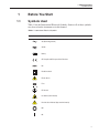
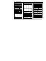
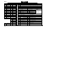
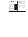
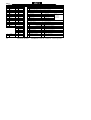
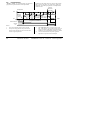
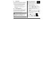
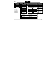
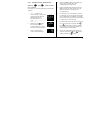
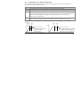
Table 1 lists the International Electrical Symbols. Some or all of these symbols
may be used on the instrument or in this manual.
Table 1 International Electrical Symbols
Symbol
Description
AC (Alternating Current)
AC-DC
Battery
CE Complies with European Union Directives
DC
Double Insulated
Electric Shock
Fuse
PE Ground
Hot Surface (Burn Hazard)
Read the User’s Manual (Important Information)
Off
On
1
9112B Calibration Furnace
User’s Guide
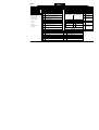
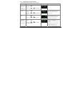
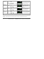
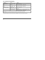
Symbol
Description
Canadian Standards Association
OVERVOLTAGE (Installation) CATEGORY II, Pollution Degree 2 per IEC1010-1 refers to the level of Impulse Withstand Voltage protection provided. Equipment of
OVERVOLTAGE CATEGORY II is energy-consuming equipment to be supplied from
the fixed installation. Examples include household, office, and laboratory appliances.
C-TIC Australian EMC Mark
The European Waste Electrical and Electronic Equipment (WEEE) Directive
(2002/96/EC) mark.
1.2
Safety Information
Use this instrument only as specified in this manual. Otherwise, the protection
provided by the instrument may be impaired.
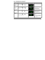
The following definitions apply to the terms “Warning” and “Caution”.
• “WARNING” identifies conditions and actions that may pose hazards to
the user.
• “CAUTION” identifies conditions and actions that may damage the instrument being used.
1.2.1
WARNINGS
To avoid personal injury, follow these guidelines.
DISCLAIMER: Hart Scientific manufactures instruments for the purpose
of temperature calibration. Instruments used for applications other than
calibration are used at the discretion and sole responsibility of the customer. Hart Scientific cannot accept any responsibility for the use of instruments for any application other than temperature calibration.
GENERAL
Appropriate personal safety protection should be worn by the operator at all
times while using the furnace.
DO NOT use the instrument for any application other than calibration work.
The instrument was designed for temperature calibration. Any other use of the
unit may cause unknown hazards to the user.
DO NOT use the unit in environments other than those listed in the user’s
guide.
Completely unattended operation is not recommended.
2
1 Before You Start
Safety Information
Follow all safety guidelines listed in the user’s manual.
Calibration Equipment should only be used by Trained Personnel.
If this equipment is used in a manner not specified by the manufacturer, the
protection provided by the equipment may be impaired or safety hazards may
arise.
Inspect the instrument for damage before each use. DO NOT use the instrument
if it appears damaged or operates abnormally.
Before initial use, or after transport, or after storage in humid or semi-humid
environments, or anytime the instrument has not been energized for more than
10 days, the instrument needs to be energized for a “dry-out” period of 2 hours
before it can be assumed to meet all of the safety requirements of the IEC
1010-1. If the product is wet or has been in a wet environment, take necessary
measures to remove moisture prior to applying power such as storage in a low
humidity temperature chamber operating at 50°C for 4 hours or more.
The instrument is intended for indoor use only.
BURN HAZARD
High temperatures may be present in this equipment. Fires and severe burns
may result if personnel fail to observe safety precautions.
The furnace generates extreme temperatures. Precautions must be taken to prevent personal injury or damage to objects. Probes may be extremely hot when
removed from the furnace. Cautiously handle probes to prevent personal injury.
Carefully place probes on a heat resistant surface rack until they are at room
temperature.
DO NOT lift the back of this instrument with the equilibration block in place.
The equilibration block will fall out of the instrument.
DO NOT operate near flammable materials. Extreme temperatures could ignite
the flammable material.
Use of this instrument at HIGH TEMPERATURES for extended periods of
time requires caution.
DO NOT touch the well access cover of the instrument, it is extremely hot.
For compliance with IEC 1010-1, it is recommended that the cutout mode always be set to the manual mode requiring user intervention to reset the
instrument.
Take extreme care in handling hot probes. The extreme temperatures generated
in a furnace of this type can cause serious personal injury. Do not touch them
on external surfaces of the furnace or set them on any other surfaces unable to
withstand those temperatures. A fire hazard exists. Do not touch the access tube
end plate or severe burns can result.
3
9112B Calibration Furnace
User’s Guide
ELECTRICAL HAZARD
These guidelines must be followed to ensure that the safety mechanisms in this
instrument will operate properly. This instrument must be plugged into a 230
VAC (± 10%) 50/60 Hz only electric outlet. The power cord of the instrument
is equipped with a three-pronged grounding plug for your protection against
electrical shock hazards. It must be plugged directly into a properly grounded
three-prong receptacle. The receptacle must be installed in accordance with local codes and ordinances. or adapter plug. Additionally, the instrument has a
Permanent Earth Ground that must be connected during use. DO NOT use an
extension cord Consult a qualified electrician.
Always replace the power cord with an approved cord of the correct rating and
type. If you have questions, contact a Hart Scientific Authorized Service Center
(see Section 1.3).
The instrument is not equipped with easily accessible fuses. The fuses are located inside the control drawer. We do not recommend replacing the fuses without calling a Hart Scientific Authorized Service Center first.
High voltage is used in the operation of this equipment. Severe injury or death
may result if personnel fail to observe the safety precautions. Before working
inside the equipment, turn off the power and disconnect the power cord.
Always ensure that the equilibration block ground is connection prior to use of
the instrument.
1.2.2
Cautions
Always operate this instrument at room temperature between 41°F and 104°F
(5°C to 40°C). Allow sufficient air circulation by leaving at least 18 inches (45
cm) of clearance around the instrument. DO NOT place instrument in a corner
or block the back of the instrument. Extreme temperatures are emitted from the
back and front of the furnace. Allow sufficient space in front of the furnace to
work and to insert and remove the probes.
Read Section 4, Installation, before placing the instrument into service.
DO NOT use fluids to clean out the well. Fluids could leak into and damage the
instrument.
Never introduce any foreign material into the probe hole of the insert. Fluids,
etc. can leak into the instrument causing damage.
DO NOT change the values of the calibration constants from the factory set
values. The correct setting of these parameters is important to the safety and
proper operation of the unit.
Read and understand the controller operation prior to operating the instrument.
The controller manufacturer’s manual is included with the instrument.
DO NOT operate this instrument in an excessively wet, oily, dusty, or dirty
environment.
4
1 Before You Start
Authorized Service Centers
The unit is a precision instrument. Although it has been designed for optimum
durability and trouble free operation, it must be handled with care.
Most probes have handle temperature limits. Be sure that the probe handle temperature limit is not exceeded in the air above the instrument.
The instrument and any thermometer probes used with it are sensitive instruments that can be easily damaged. Always handle these devices with care. Do
not allow them to be dropped, struck, stressed, or overheated.
When calibrating PRTs always follow correct calibration procedure and calibrate from high temperatures to low temperatures with the appropriate triple
point of water checks. Never immerse a wet or cold PRT into a bath filled with
hot medium. Severe damage to the PRT may result as well as personal injury to
the calibration technician.
This furnace is not designed to be portable. Therefore, moving the furnace once
it has been installed should be kept to a minimum. To safely move the furnace,
two people are required. One person should lift the furnace at each end of the
furnace, place their hand under the control drawer, and lift simultaneously being careful not to tip. Ensure that the furnace is de-energized and cooled to less
then 100°C. Remove the equilibration block prior to moving. The equilibration
block can damage the fused silica tube that is extremely fragile.
The control probe must be inserted properly in the instrument and plugged into
the socket at the back of the furnace. DO NOT operate the furnace without the
control probe properly inserted and attached. The furnace will not operate correctly without the control probe. Injury to operating personnel and permanent
damage to the furnace could occur.
Components and heater lifetimes can be shortened by continuous high temperature operation.
If a mains supply power fluctuation occurs, immediately turn off the furnace.
Power bumps from brown-outs and black-outs can damage the instrument. Wait
until the power has stabilized before re-energizing the furnace.
The probe and the block may expand at different rates. Allow for probe expansion inside the well as the block heats. Otherwise, the probe may become stuck
in the well.
Be aware that the equilibration block expands as the furnace heats. It will extend beyond the front of the furnace at high temperatures anywhere from ¼ to
approximately ½ inch. This is normal and is due to thermal expansion.
Take care that all sensors used as references or being calibrated in the furnace
are capable of withstanding the desired temperature range to be used.
1.3
Authorized Service Centers
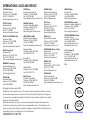
Please contact one of the following Authorized Service Centers to coordinate
service on your Hart product:
5
9112B Calibration Furnace
User’s Guide
Fluke Corporation Hart Scientific Division
799 E. Utah Valley Drive
American Fork, UT 84003-9775
USA
Phone: +1.801.763.1600
Telefax: +1.801.763.1010
E-mail: [email protected]
Fluke Nederland B.V.
Customer Support Services
Science Park Eindhoven 5108
5692 EC Son
NETHERLANDS
Phone: +31-402-675300
Telefax: +31-402-675321
E-mail: [email protected]
Fluke Int'l Corporation
Service Center - Instrimpex
Room 2301 Sciteck Tower
22 Jianguomenwai Dajie
Chao Yang District
Beijing 100004, PRC
CHINA
Phone: +86-10-6-512-3436
Telefax: +86-10-6-512-3437
E-mail: [email protected]
Fluke South East Asia Pte Ltd.
Fluke ASEAN Regional Office
Service Center
60 Alexandra Terrace #03-16
The Comtech (Lobby D)
118502
SINGAPORE
6
1 Before You Start
Authorized Service Centers
Phone: +65 6799-5588
Telefax: +65 6799-5588
E-mail: [email protected]
When contacting these Service Centers for support, please have the following
information available:
• Model Number
• Serial Number
• Voltage
• Complete description of the problem
7
2 Introduction
2
Introduction
The 9112B Calibration Furnace was designed specifically for calibrating PRTs,
fiber optic sensors and thermocouples at higher temperature ranges up to
1100°C. The furnace utilizes an equilibration block capable of making comparison measurements on multiple probes. The standard equilibration block is
sized for ¼ inch probes, however, custom options are possible. Temperature
stability is better than ± 0.1°C throughout the range and the gradient between
wells at full insertion is less than 0.5°C (± 0.25°C).
The temperature control system utilizes a digital controller with a Type K thermocouple control sensor and RS-232 interface. The controller displays the set
temperature and the actual temperature simultaneously. The display shows temperature to the nearest degree in °C or °F (shipped in °C). The temperature is
set with convenient up and down buttons on the front panel.
Sensors being calibrated as well as the furnace itself are protected from excessive temperature with an over-temperature cutout. The cutout is easily adjusted
from the front panel. This device is relay operated and protects against the possibility of thermal runaway due to a shorted solid-state relay which controls the
heaters.
9
3 Specifications and Environmental Conditions
Specifications
3
3.1
3.2
Specifications and Environmental
Conditions
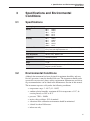
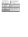
Specifications
Operating Range
300°C to 1100°C
Stability
300°C
500°C
700°C
1000°C
1100°C
±0.05°C
±0.05°C
±0.1°C
±0.1°C
±0.1°C
Uniformity
300°C
500°C
700°C
1000°C
1100°C
±0.05°C
±0.08°C
±0.2°C
±0.25°C
±0.3°C
Stabilization Time
Typically 2 hours midrange, slower at the low temperature end (4
hours), faster at the high temperature end
Heater Power
3700 Watts High
Power Requirements
230 VAC (±10%), 50/60 Hz, 20 A
System Fuse
20 A 250 V Fast Blow
Outside Dimensions
18” H x 14.25”W x 26”D (457mm x 362mm x 660mm)
Weight
72.5 lbs
Safety
OVERVOLTAGE (Installation) CATEGORY II, Pollution
Degree 2 per IEC-61010-1
Environmental Conditions
Although the instrument has been designed for optimum durability and trouble-free operation, it must be handled with care. The instrument should not be
operated in an excessively dusty or dirty environment. Maintenance and cleaning recommendations can be found in the Maintenance Section of this manual.
The instrument operates safely under the following conditions:
• temperature range: 5 - 40°C (41 - 104°F)
• ambient relative humidity: maximum 80% for temperature <31°C, decreasing linearly to 50% at 40°C
• pressure: 75kPa - 106kPa
• mains voltage within ± 10% of nominal
• vibrations in the calibration environment should be minimized
• altitude less than 2000 meters
• indoor use only
11
4 Installation
Unpacking & Inspection
4
4.1
Installation
Unpacking & Inspection
The furnace has been carefully packed for safe shipment by traditional means.
Unpacking should be done carefully. Check carefully for all parts. If any damage has occurred, you should notify the shipper immediately and make the appropriate claim.
The equilibration block assembly has been packed separately in order to protect
the fused silica tube from breakage during shipment. The block assembly
should not be installed into the furnace until it has been placed in its final
location.
Verify that the following components are present:
• Furnace
• 2 – Thermocouples
• Equilibration Block Assembly (2 pieces)
• Block Assembly Instruction Sheet
• Controller Manual
• User’s Guide
• Serial Cable
4.2
Location
The furnace is intended to be installed into any typical calibration facility environment. The best results from the furnace are realized if the temperature fluctuations in the room are not excessive. A minimum of 18 inches free air space
around the furnace must be allowed. This air space allows exchange to occur
and safely remove heat from the furnace.
WARNING: This furnace is intended for high temperature use and consequently a fire danger exists. DO NOT mount the furnace on a flammable
surface and keep fire-extinguishing equipment near by.
Extremely humid environments may require startup on low heat after long periods of disuse.
13
9112B Calibration Furnace
User’s Guide
4.3
“Dry-out” Period
WARNING: Before initial use, after transport, and any time the instrument has not been energized for more than 10 days, the instrument needs
to be energized for a “dry-out” period of 1-2 hours before it can be assumed to meet all of the safety requirements of the IEC 1010-1. If the
product is wet or has been in a wet environment, take necessary measures
to remove moisture prior to applying power such as storage in a low humidity temperature chamber operating at 50°C for 4 hours or more.
4.4
Power
The furnace utilizes a grounded AC supply of 230 VAC (±10%), 20 amps, single phase, 50/60 HZ. An eight foot 2 conductor with ground, power cord is provided. A separate ground connection is provided and required to permanently
connect the instrument to earth ground for added operator safety.
WARNING: Ensure accessability to the mains plug for disconnection
from supply source.
4.5
Equilibration Block Assembly Installation
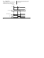
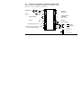
After the furnace has been installed and the permanent earth ground appropriately attached, the equilibration block assembly may be inserted. Carefully insert the block assembly into the tube with its insulation packing per Figure 2 on
page 17. Extreme care should be taken installing the Equilibration Block since
it is very heavy and the fused silica tube is very fragile. A 1/8 to ¼ inch air gap
between the front access plate and the front panel of the furnace is required in
order to prevent the front panel from getting too hot. Care must be taken to prevent dirt, insulation, or anything else from getting between the block and the
fused silica tube or it might break during heat up due to thermal expansion differences. The fit between the block and the tube is typically loose in order to
accommodate this expansion.
CAUTION: If the furnace must be moved for any reason, remove the
block assembly to prevent breakage of the fused silica tube.
4.6
Probe Installation
Install the temperature control and over temperature cutout probes as shown in
Figure 2 and Figure 3 on pages 17 and 18. Insert the probes carefully to the
depth shown in order to insure that the sensor is properly located in the equilibration block. Be sure to connect the probes properly on the rear panel.
14
5 Parts and Controls
Front View
5
5.1
Parts and Controls
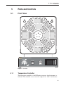
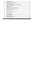
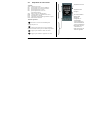
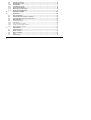
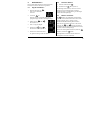
Front View
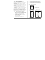
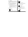
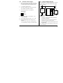
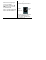
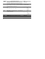
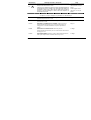
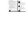
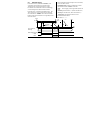
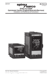
Figure 1 Front View
5.1.1
Temperature Controller
The temperature controller is a full PID micro-processor based instrument as
indicated. The controller is set to cover the range of 0 to 1100°C and features
15
9112B Calibration Furnace
User’s Guide
two LED type displays. The upper display normally indicates the actual temperature while the lower display indicates the set temperature. The displays are
also utilized in setup and alarm functions. Other indicators include the OP1 and
OP2 indicator lights. The OP1 indicator lights when the heater is on. The OP2
is not functional on the unit. The “R” indicator lights during programmed
ramping. The “M” indicator flashes if the sensor fails. If the sensor opens, the
heaters shut off.
The up and down Temperature Adjustment arrow keys are the only temperature
controls normally used. A quick single stroke increments or decrements the
temperature setting. Holding the buttons down causes a gradual acceleration of
the temperature setting. These same buttons are used to adjust other parameters
in conjunction with the “PAR” button.
Further information about the controller operation can be obtained from the
temperature controller installation and operation manual included with the
instrument.
5.1.2
Over Temperature Cutout
The over temperature cutout is located at the left side of the control panel. The
controls include a temperature limit adjustment control knob calibrated in Celsius and “limit exceeded” indicator light. The cutout is adjustable by the user
within the temperature range of the furnace with divisions shown every 25°C.
The indicator light turns on when the set limit is reached. The cutout can be set
to Manual Reset or Auto Reset. The button on front panel allows the user to reset the cutout. The unit leaves the factory with the unit set in the Manual Reset
Mode. In the Auto Reset Mode, the temperature resets when it has dropped
about 20 degrees.
The cutout is provided to allow the user to set the maximum furnace temperature to a point within the safe range of the sensor(s) being calibrated and to protect the furnace from exceeding its own safe operating range. Limiting the top
end also helps extend the life of the heaters.
The cutout controls a relay which is wired in series with the heater circuit. The
cutout is provided as a safety backup in case the solid state relay driven by the
temperature controller fails (shorts) causing thermal runaway.
5.1.3
Power and Heater Switches
The power switch is located just left of the temperature controller. The top is
pressed inward to turn the unit on.
NOTE: The internal fans will stay on until the unit is cooled even though
the main power may have been turned off. This keeps the outer surfaces of
the enclosure from being heated to dangerous levels from stored heat.
16
5 Parts and Controls
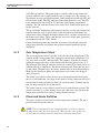
Heater Assembly
5.2
Heater Assembly
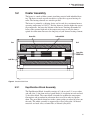
The heater is a made of fiber ceramic insulating material with imbedded heating. The heater is made up with two halves, each with a separate heating element. The heating elements are wired in parallel.
The heater is primarily a radiating device and is rated for a maximum furnace
operating temperature of 1100°C. Realize, however, that the higher the operating temperature, the lower the lifetime of the heater. Limiting the number of
hours at the extreme high end of the temperature range to only the time required for calibrations increases the longevity of your furnace heating element.
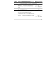
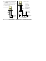
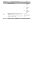
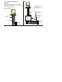
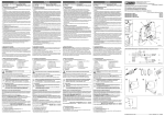
Quartz Tube
Isothermal Block
Back
Front
Cutout Probe
Control Probe
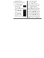
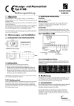
Guide Tubes
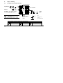
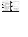
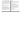
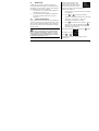
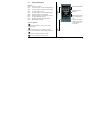
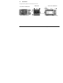
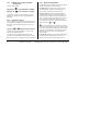
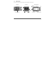
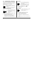
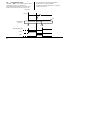
Figure 2 Sectional Side View
5.2.1
Equilibration Block Assembly
The Equilibration Block Assembly consists of 1) the test well, 2) access tubes
and end plate, 3) the front and rear guard blocks, 4) insulation on each end and
5) the center block. The center block is intended to stabilize the temperature
fluctuations and to conduct heat between the test wells in order to equalize
them. The guard blocks shunt heat to the various probes to reduce heat loss out
the ends. The whole assembly is supported by a fused silica tube. All heated
materials are fused silica, ceramic fiber, or Inconel (alloy 600).
17
9112B Calibration Furnace
User’s Guide
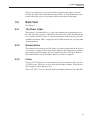
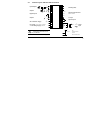
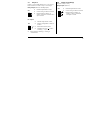
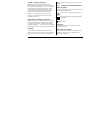
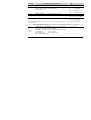
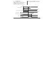
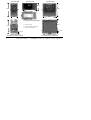
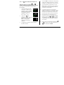
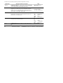
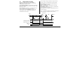
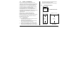
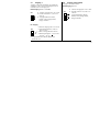
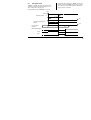
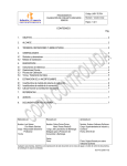
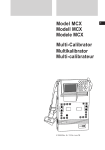
Figure 3 Back View
5.2.2
Temperature Control and Cutout Sensor
The temperature control sensor is a type K thermocouple. This sensor is 3/16
inch in diameter and 12 inches long. Its location in the block is important and
can cause the gradient in the block to move back and forth. The probe is normally inserted as shown in Figures 2 and 3.
The cutout sensor is the same as the control sensor, 12 inches long. This sensor
is inserted through a tube in the back of the block. Its location here helps prevent the heater elements from overheating thus prolonging their life.
18
5 Parts and Controls
Back View
The sensor connectors are provided on the rear panel of the furnace for connecting the control and cutout thermocouples. They are Type K miniature connectors and allow for ease of system assembly and sensor replacement.
5.3
Back View
See Figure 3.
5.3.1
The Power Cable
The furnace is provided with a 12 gauge two conductor with ground power cable. The user must provide a connector to meet the needs of the installation. Be
sure to follow electrical codes. A separate permanent earth ground is provided
with this instrument. This is required to be installed correctly for safe operation
of the instrument.
5.3.2
Nomenclature
The nomenclature on the rear of the furnace provides information to the user in
case service is required. The nomenclature includes the manufacturer, manufacturer location, model number, and serial number specific to this unit. Refer to
the model number and serial number whenever service is required.
5.3.3
Fuses
Two 20 A F 250 V fuses are used to protect the system, one for each leg of the
230 VAC power. The fuses are located inside the control cabinet. If the furnace
fails to operate, check the fuses first.
Two 1 A F 250 V fuses are located inside the control cabinet for the controller.
19
6 Operation
Overview
6
6.1
Operation
Overview
The Model 9112B is basically a temperature controlled furnace utilizing a full
PID micro-processor based temperature controller with a Type K thermocouple
temperature sensor. The temperature controller sends a time proportional signal
to the solid state relay which regulates the current to the heater. The heater
power can be switched to HIGH or LOW power positions. The object of the
temperature control is the equilibration block with test wells containing the reference probe and the sensors to be calibrated inside. The block provides a thermal mass which tends to stabilize the temperature and reduce the gradients
between the test wells. The user settable “over-temperature cut-out” can open
the heater circuit with a relay if the safe temperature for the test probe or for
the furnace is exceeded. The enclosure is designed to limit the heat seen by the
various components of the furnace as well as the user. The control section is in
a separate cabinet below the furnace heat preventing damage or accuracy errors. The furnace part of the cabinet contains ventilation holes as well as two
fans controlled by the thermostat. This cooling capability prevents the surface
of the enclosure from getting dangerously hot. In the event that the fans should
fail, a second thermostat is installed in the cabinet which shuts down the furnace heaters if the cabinet exceeds a safe temperature.
6.2
Operating the Furnace
When the unit is turned on, the cutout reset button must be pushed before the
unit will heat.
Operating the Model 9112B is straight forward. Temperature selection is accomplished by using the enter key (circular arrow) until SP1 is displayed. Next,
the up and down arrow keys are used to change the set-point temperature. The
lower display indicates the new temperature setting while the upper display
shows the actual temperature. When scanning from one temperature to another,
notice that the temperature controller seems to be ahead of the equilibration
block temperature. This difference is because the temperature control sensor is
near the outside of the block and it takes some time for the heat to conduct into
the center. Depend on an external temperature monitor to establish when the
equilibration block has reached the desired temperature and achieved stability.
CAUTION: Take care that all sensors used as references or being calibrated in the furnace are capable of withstanding the desired temperature
range to be used.
21
9112B Calibration Furnace
User’s Guide
WARNING:
Take extreme care in handling hot probes. The extreme temperatures generated in a furnace of this type can cause serious
personal injury. Do not touch them on external surfaces of the furnace or
set them on any other surfaces unable to withstand those temperatures. A
fire hazard exists. Do not touch the access tube end plate or severe burns
can result.
Some kind of metal and/or ceramic fiber surface or container should be used to
set the hot probes on to prevent injury, damage, and fire.
For best results, all reference or sample probes should be inserted into the full
depth of the well. At this position the stability is the highest and the gradient
the lowest. Each user should satisfy themselves as to what the uncertainties are
in terms of stability and gradients between the test wells. Variations in equipment, probe size, configuration, etc affect these important factors. A solid
(unstirred) mass such as in a furnace is subject to heat losses from the probe
stem which varies from probe to probe and temperature to temperature. Typically, stabilities are less than ±0.1°C and can be as little as ±0.015°C at 500°C.
Similarly, gradients between the measuring cells can range from ±0.2°C to well
under ±0.1°C. For calibrations that must be less than full insertion into the test
well, make your own comparisons between the reference and test cell at that
depth to establish the uncertainties.
The furnace can be used throughout the temperature range of 300 to 1100°C.
Lower temperatures are sluggish however. High integrating values are required
to maintain controller stability (1200 sec) at the lower temperatures. Expect
some offset from the indicated temperature and the actual temperature. Stability
and gradients between test wells are similar at higher temperatures but time to
stability is much longer.
22
7 Digital Communication Interface
7
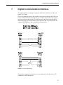
Digital Communication Interface
To control the furnace through a computer, follow the instructions in the controller User Guide.
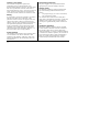
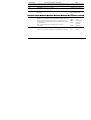
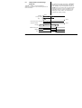
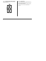
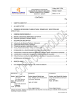
The serial communications cable attaches to the furnace through the DB-9 connector at the back of the instrument. Figure 4 shows the pin-out of this connector and suggested cable wiring. To eliminate noise, the serial cable should be
shielded with low resistance between the connector (DB-9) and the shield. An
adequate Null MOdem cable is included with the furnace.
Figure 4 RS-232 Cable Wiring
Connect the appropriate connectors to your computer and to the furnace. To
communicate with the furnace.
23
9112B Calibration Furnace
User’s Guide
24
8 Maintenance
8
Maintenance
The calibration instrument has been designed with the utmost care. Ease of operation and simplicity of maintenance have been a central theme in the product
development. Therefore, with proper care the instrument should require very
little maintenance. Avoid operating the instrument in an oily, wet, dirty, or
dusty environment.
• If the outside of the instrument becomes soiled, it may be wiped clean
with a damp cloth and mild detergent. Do not use harsh chemicals on the
surface which may damage the paint.
• Be sure that the well of the furnace is kept clean and clear of any foreign
matter. Do not use fluids to clean out the well.
• If a hazardous material is spilt on or inside the equipment, the user is responsible for taking the appropriate decontamination steps as outlined by
the national safety council with respect to the material.
• If the mains supply cord becomes damaged, replace it with a cord with
the appropriate gauge wire for the current of the instrument. If there are
any questions, contact an Authorized Service Center (see Section 1.3) for
more information.
• Before using any cleaning or decontamination method except those recommended by Hart, users should check with an Authorized Service Center to be sure that the proposed method will not damage the equipment.
• If the instrument is used in a manner not in accordance with the equipment design, the operation of the furnace may be impaired or safety hazards may arise.
• The over-temperature cut-out should be checked every 6 months to ensure
that it is working properly. Set the unit to 300°C and let it stabilize. Turn
the adjustable cutout knob down until the cutout is activated. Turn the
knob back up and push the reset button.
• Periodically remove the equilibration block and use emery cloth to remove the oxidation build up on the block.
25
PID Temperature
controllers
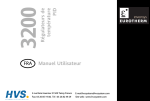
3200
ENG
User Guide
FRA
Manuel Utilisateur
GER
Bedienungsanleitung
E U ROT H E R M
This booklet includes:
User Guide (HA028582 Issue 3)
Manuel Utilisateur (HA028582FRA Indice 3)
Bedienungsanleitung (HA028582GER Ausgabe 3)
3200 Series PID Temperature Controllers
Applies to Model numbers 3216, 3208, 32h8 and 3204
Contents
1.
What Instrument Do I Have? ............................................................................ 4
1.1
1.2
1.3
1.3.1
1.3.2
1.3.3
1.3.4
1.4
2.
Unpacking Your Controller .................................................................................................4
Dimensions .........................................................................................................................5
Step 1: Installation.............................................................................................................7
Panel Mounting the Controller ............................................................................................................................... 7
Panel Cut-out Sizes ..................................................................................................................................................... 7
Recommended minimum spacing of controllers. Applies to all Model sizes.......................................... 8
To Remove the Controller from its Sleeve.......................................................................................................... 8
Ordering Code ....................................................................................................................9
Step 2: Wiring.................................................................................................10
2.1
Terminal Layout 3216 Controller .......................................................................................10
Terminal Layout 3208 and 3204 Controllers.......................................................................11
2.3
Terminal Layout 32h8 Controller.......................................................................................12
Wire Sizes .........................................................................................................................13
Sensor Input (Measuring Input) ........................................................................................13
Input/Output 1 & Output 2 ...............................................................................................14
2.2
2.4
2.5
2.6
Part number HA028582 Issue 3.0, Oct-05. Applies to software versions 2.07 and 2.27
T
1
2.7
2.8
2.9
2.10
2.11
2.12
2.13
2.14
3.
Safety and EMC Information............................................................................20
3.1
4.
Installation Safety Requirements ...................................................................................... 21
Switch On ........................................................................................................25
4.1
4.2
4.3
4.4
4.4.1
4.4.2
4.4.3
4.4.4
4.4.5
2
Output 3........................................................................................................................... 15
Output 4 (AA Relay) ......................................................................................................... 15
Digital Inputs A & B.......................................................................................................... 16
Current Transformer ........................................................................................................ 17
Transmitter Power Supply ................................................................................................ 17
Digital Communications ................................................................................................... 18
Controller Power Supply................................................................................................... 19
Example Wiring Diagram .................................................................................................. 19
Initial Configuration ......................................................................................................... 25
To Re-Enter Quick Code configuration mode .................................................................... 28
Pre-Configured Controller or Subsequent Starts ............................................................... 28
Front panel layout............................................................................................................ 29
To Set The Target Temperature (setpoint) ....................................................................................................... 30
Alarm Indication ........................................................................................................................................................ 30
Auto, Manual and Off Mode ................................................................................................................................. 30
To Select Auto, Manual or OFF Mode ................................................................................................................ 31
Operator Parameters in Level 1............................................................................................................................ 32
5.
Operator Level 2..............................................................................................33
5.1
5.2
5.3
5.4
5.5
5.6
5.7
5.8
5.8.1
5.8.2
5.8.3
To Enter Level 2 ................................................................................................................33
To Return to Level 1 .........................................................................................................33
Level 2 Parameters............................................................................................................33
Timer Operation ...............................................................................................................42
Dwell Timer ......................................................................................................................43
Delayed Timer ..................................................................................................................44
Soft Start Timer ................................................................................................................45
Programmer......................................................................................................................46
Programmer Servo Mode and Power Cycling................................................................................................... 47
To Operate the Programmer ................................................................................................................................. 48
To Configure the Programmer.............................................................................................................................. 49
3
Installation and Basic Operation
1. What Instrument Do I Have?
Thank you for choosing this 3200 series Temperature
Controller/Programmer.
The 3200 series provide precise temperature control
of industrial processes and is available in three
standard DIN sizes:•
1/16 DIN Model Number 3216
•
1/8 DIN Model Number 3208
•
1/8 DIN Horizontal Model Number 32h8
•
1/4 DIN Model Number 3204
A universal input accepts various thermocouples,
RTDs or process inputs. Up to three (3216) or four
(3208, 32h8 and 3204) outputs can be configured for
control, alarm or re-transmission purposes. Digital
communications and a current transformer input are
available as options.
The controller may have been ordered to a hardware
code only or pre-configured using an optional ‘Quick
Start’ code. The label fitted to the side of the sleeve
shows the ordering code that the controller was
supplied to. The last two sets of five digits show the
Quick Code. If the Quick Code shows *****/*****
4
the controller will need to be configured when it is
first switched on.
This User Guide takes you through step by step
instructions to help you to install, wire, configure and
use the controller. For features not covered in this
User Guide, a detailed Engineering Manual, Part No
HA027986, and other related handbooks can be
downloaded from www.eurotherm.co.uk.
1.1
Unpacking Your Controller
The following items are included in the box:
•
Controller mounted in its sleeve
•
Two panel retaining clips
•
AN IP65 sealing gasket mounted on the sleeve
•
Component packet containing a snubber for
each relay output and a 2.49Ω resistor for
current inputs (see section 2)
•
This User Guide
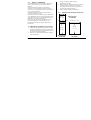
1.2
Dimensions
The following two pages show general views of the controllers together with overall dimensions.
3216 Top View
3216 Front View
3216 Side View
1.25mm (0.5in)
90mm (3.54in)
48mm
(1.89in)
Latching ears
Panel retaining clip
48mm
(1.89in)
IP65 Sealing Gasket
Panel retaining clips
5
32h8 Front
3208 Front
3204 Front
48mm
(1.89in)
96mm
(3.78in)
1
96mm (3.78in)
96mm
(3.78in)
1
1
48mm
(1.89in)
96mm (3.78in)
32h8 Side
with Panel Retaining Clips
90mm
(3.54in)
3
2
1.25mm
(0.5in)
3208 Top
with Panel Retaining Clip
6
90mm
(3.54in)
1 Latching ears
2 Panel Retaining Clip
3 IP65 Sealing Gasket
3
1.25mm
(0.5in)
32h8 and 3204 Top
without Panel Retaining Clip
1.3
Step 1: Installation
This controller is intended for permanent
installation, for indoor use only, and enclosed in an
electrical panel
Select a location which is subject to minimum
vibrations, the ambient temperature is within 0 and
55oC (32 - 131oF) and humidity 5 to 95% RH non
condensing.
The controller can be mounted on a panel up to
15mm thick
To ensure IP65 and NEMA 4 front sealing against
dust and water, mount on a non-textured surface.
Please read the safety information in section 3
before proceeding. The EMC Booklet part number
HA025464 gives further installation information.
1.3.1 Panel Mounting the Controller
1. Prepare a cut-out in the mounting panel to the
size shown. If a number of controllers are to be
mounted in the same panel observe the
minimum spacing shown.
2. Fit the IP65 sealing gasket behind the front
bezel of the controller
3. Insert the controller through the cut-out
4.
5.
Spring the panel retaining clips into place.
Secure the controller in position by holding it
level and pushing both retaining clips forward.
Peel off the protective cover from the display
1.3.2
Panel Cut-out Sizes
45 mm
- 0.0 + 0.6
1.77 inch
1/16 DIN Cut Out
-0.00, +0.02
45 mm - 0.0 + 0.6
92 mm - 0.0 + 0.8
1.77 inch -0.00, +0.02
3.62 inch -0.00, +0.03
92 mm
92 mm
- 0.0 + 0.8
- 0.0 + 0.8
3.62 inch
-0.00, +0.03
3.62 inch
-0.00, +0.03
. 1/8 DIN Cut Out
1/4 DIN Cut Out
7
1.3.3
Recommended minimum spacing of
controllers. Applies to all Model
sizes
10mm (0.4 inch)
38mm (1.5 inch)
(Not to scale)
8
1
1.3.4
To Remove the Controller from its
Sleeve
The controller can be unplugged from its sleeve by
easing the latching ears outwards and pulling it
forward out of the sleeve. When plugging it back
into its sleeve, ensure that the latching ears click
back into place to maintain the IP65 sealing.
1.4
Ordering Code
1
2
3
4
5
6
7
8
9
10
11
12
4. Outputs 1, 2 and 3 3208/H8/04
1. Model No.
1/16 DIN size
1/8 DIN size
1/8 DIN horizontal
1/4 DIN size
3216
3208
32h8
3204
2. Function
Controller
Programmer
valve controller
Valve programmer
CC
CP
VC
VP
3. Power Supply
24Vac/dc
VL
100–240Vac
VH
OP1
X
L
R
L
L
R
D
L
D
L
T
L
T
OP2
X
R
R
L
R
R
D
L
R
T
T
T
T
OP3
X
R
R
R
D
D
D
D
D
R
R
D
D
X
X
X
X
X
X
X
X
X
X
X
X
X
13
Quick Start Code – section 4
7. Fascia colour/type
Green
G
Silver
S
Wash down fascia
W
8/9 Product/Manual Language
English
ENG
French
FRA
German
GER
Italian
ITA
Spanish
SPA
10. Extended Warranty
Standard
XXXXX
Extended
WL005
5. AA Relay (OP4)
11. Certificates
Disabled
X
None
XXXXX
Relay (Form C)
R
CERT1
Cert of conformity
X
X
CERT2
Factory calibration
X
X
6. Options
X
X
Not fitted
XXX
12. Custom Label
X
X
RS485 & Digital input A
4XL
XXXXX
None
X
X
RS232 & Digital input A
2XL
X
X
13. Specials Number
RS485,
CT
&
Dig
in
A
4CL
X
X
XXXXXX
None
RS232, CT & Dig in A
2CL
X
X
RES250
250Ω ; 0-5Vdc OP
Digital input A
XXL
X
X
RES500
500Ω ; 0-10Vdc OP
CT & Digital input A
XCL
X
X
Triac not available with low voltage supply option. L = Logic; R = Relay; D = DC; T = Triac
4. Outputs 1 and 2 3216
OP1
X
L
L
R
L
L
D
D
L
T
OP2
X
X
R
R
L
D
D
R
T
T
9
2.
Step 2: Wiring
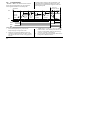
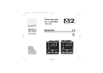
2.1
Terminal Layout 3216 Controller
CT input & Digital input A
Input/Output 1
Output 2
+
+
1A
CT
-
-
1B
C
AB
+
+
2A
LA
AC
-
-
2B
COM HD
VI
L
A(+) HE
V+
N
B(-) HF
V-
Line Supply 100 to 240Vac 50/60Hz
OR Low Voltage Supply 24Vac/dc
AA
AA relay (OP4)
2.49Ω
-
T/C
!
Ensure that you have the correct
supply for your indicator.
Check order code of the indicator supplied
+
+
+
Digital
Communications
RS232
RS485
Pt100
-
mA
mV
-
+
10V Input
-
Sensor
Input
10V
Potential divider
module
Part No SUB21/IV10
Key to symbols used in this and following wiring diagrams
10
Logic (SSR drive) output
Relay output
Contact input
mA analogue output
Triac output
Current transformer input
2.2
Terminal Layout 3208 and 3204 Controllers
Input/Output 1
Output 2
+
-
+
-
+
-
24V Transmitter Supply
AB
AA Relay (OP4)
AC
2B
HD
COM
LB
HE
A(+)
LC
HF
B(-)
NO
3A
CT
C
3B
C
3C
LA
3D
VI
L
V+
N
V-
+
-
Digital Input B
Output 3
AA
1B
2A
+
-
1A
+
24V
-
Line Supply 100 to 240Vac 50/60Hz
OR Low Voltage Supply 24Vac/dc
Digital Communications
RS232 or RS485
CT input
Digital input A
+
+
-
T/C
Pt100
+
!
Ensure that you have the correct
supply for your indicator.
Check order code of the indicator supplied
+
2.49Ω
10V Input
-
-
mA
-
Sensor
Input
mV
10V
Potential divider
module
Part No SUB21/IV10
11
2.3
Terminal Layout 32h8 Controller
Input/
Output Output1
2
!
Ensure that you have the correct
supply for your indicator.
Check order code of the indicator supplied
+
24V
Transmitter
Supply
-
Line Supply
100 to 240Vac 50/60Hz
OR
Low Voltage Supply
24Vac/dc
N
Output
3
L
3D 3C
+
-
C
NO
3B
3A
Dig
in B
LC
+
-
+
-
+
-
+
-
C
NO C
NO
2B
2A
1B
1A
HE HD AC AB
AA
LB
32h8 Controller
Sensor Input
V-
-
VI
12
10V Input
+
-
mA/mV
C
CT
HF
+
Pt100
-
LA
+
2.49Ω
CT input
T/C
V+
Dig in A
10V
Potential divider
module
Part No SUB21/IV10
B(-) A(+) COM
Digital Comms
AA Relay
(OP4)
2.4
Wire Sizes
The screw terminals accept wire sizes from 0.5 to 1.5
mm (16 to 22AWG). Hinged covers prevent hands or
metal making accidental contact with live wires. The
rear terminal screws should be tightened to 0.4Nm
(3.5lb in).
2.5
•
•
•
•
Sensor Input (Measuring Input)
Do not run input wires with power cables
When shielded cable is used, it should be
grounded at one point only
Any external components (such as zener barriers)
connected between sensor and input terminals
may cause errors in measurement due to
excessive and/or un-balanced line resistance, or
leakage currents.
Not isolated from the logic outputs & digital
inputs
Thermocouple Input
V+ +
V-
•
RTD Input
•
VI
PRT
V+
PRT
V-
Lead compensation
The resistance of the three wires must be the
same. The line resistance may cause errors if it
exceeds 22Ω.
Linear mA, mV or Voltage Inputs
V+
V-
•
•
2.49Ω
Positive
Negative
-
For a mA input connect the 2.49Ω burden
resistor supplied between the V+ and Vterminals as shown
For a 0-10Vdc input an external input adapter is
required (not supplied). Part number:
SUB21/IV10.
Positive
Negative
Use the correct compensating cable preferably
shielded.
+
+
V+
V-
0-10V Input
13
2.6
Input/Output 1 & Output 2
May be configured as input or output.
Outputs can be logic (SSR drive), or relay, or mA dc.
Input is contact closure.
Relay Output (Form A, normally open)
OP1/2
1(2) A
1(2)B
•
•
•
Isolated output 240Vac CATII
Contact rating: 2A 264Vac resistive
Output functions: Heating, or
cooling, or alarm or motorised
valve open or closed
Logic (SSR drive) Output
•
•
Not isolated from the sensor input
Output ON state: 12Vdc at 40mA
1(2) A +
max
1(2)B • Output OFF state: <300mV,
<100μA
• Output functions: Heating, or
cooling, or alarm or motorised
valve open or closed
• The output switching rate must be set to prevent
damage to the output device in use. See
parameter 1.PLS or 2.PLS in section 5.3.
OP1/2
14
DC Output
•
•
OP1/2
Not isolated from the sensor input
Software configurable: 0-20mA or
1(2) A +
4-20mA.
1(2)B • Max load resistance: 500Ω
• Calibration accuracy: +(<1% of
reading + <100μA)
• Output functions: Heating, or cooling, or
retransmission.
Triac Output
• Isolated output 240Vac CATII
• Rating: 0.75A rms, 30 to 264Vac
resistive
1(2) A
1(2)B
Logic Contact Closure Input (OP1 only)
OP1
1A
1B
•
•
•
•
Not isolated from the sensor input
Switching: 12Vdc at 40mA max
Contact open > 500Ω. Contact
closed < 150Ω
Input functions: Please refer to the
list in the Quick Start codes.
2.7
Output 3
Output 3 is not available model 3216. In 1/8 and 1/4
DIN controllers it is either a relay or a mA output.
2.8
Relay Output (Form C)
Relay Output (Form A, normally open)
OP3
3A
•
•
•
3B
Isolated output 240Vac CATII
Contact rating: 2A 264Vac resistive
Output functions: Heating, or
cooling, or alarm or motorised valve
open or closed
Output 4 (AA Relay)
Output 4 is always a relay.
OP4
AA
AB
AC
•
•
•
Isolated output 240Vac CATII
Contact rating: 2A 264Vac resistive
Output functions: Heating, or
cooling, or alarm or motorised
valve open or closed
DC Output
•
•
Isolated output 240Vac CATII
Software configurable: 0-20mA or
4-20mA
3A +
• Max load resistance: 500Ω
3B • Calibration accuracy: +(<0.25%
of reading + <50μA
• Output functions: Heating, or cooling, or
retransmission.
OP3
15
* General Notes about Relays and Inductive
Loads
High voltage transients may occur when switching
inductive loads such as some contactors or solenoid
valves. Through the internal contacts, these transients
may introduce disturbances which could affect the
performance of the instrument.
For this type of load it is recommended that a
‘snubber’ is connected across the normally open
contact of the relay switching the load. The snubber
recommended consists of a series connected
resistor/capacitor (typically 15nF/100Ω). A snubber
will also prolong the life of the relay contacts.
A snubber should also be connected across the output
terminal of a triac output to prevent false triggering
under line transient conditions.
WARNING
When the relay contact is open, or it is connected
to a high impedance load, it passes a current
(typically 0.6mA at 110Vac and 1.2mA at 240Vac).
You must ensure that this current will not hold on
low power electrical loads. If the load is of this
type the snubber should not be connected.
16
2.9
Digital Inputs A & B
Digital input A is an optional input in all Model sizes.
Digital input B is always fitted in the Models 3208,
32h8 and 3204.
•
•
•
•
Dig in
A
C
Dig in
B
LB
LA
LC
Not isolated from the sensor input
Switching: 12Vdc at 40mA max
Contact open > 500Ω. Contact closed < 200Ω
Input functions: Please refer to the list in the
quick codes.
2.10
Current Transformer
•
The current transformer input is an optional input in
all model sizes.
It can be connected to monitor the rms current in an
electrical load and to provide load diagnostics. The
following fault conditions can be detected: SSR (solid
state relay) short circuit, heater open circuit and partial
load failure. These faults are displayed as alarm
messages on the controller front panel.
CT Input
CT
Note: C is common to both the CT input and Digital
input A. They are, therefore, not isolated from each
other or the PV input.
•
•
2.11
C
•
•
CT input current: 0-50mA rms (sine wave,
calibrated) 50/60Hz
A burden resistor, value 10Ω, is fitted inside the
controller.
It is recommended that the current
transformer is fitted with a
voltage limiting device to prevent
high voltage transients if the
controller is unplugged. For
example, two back to back zener diodes. The
zener voltage should be between 3 and 10V,
rated at 50mA.
CT input resolution: 0.1A for scale up to 10A,
1A for scale 11 to 100A
CT input accuracy: +4% of reading.
Transmitter Power Supply
The Transmitter Supply is not available in the Model
3216. It is fitted as standard in the Models 3208 and
3204.
Transmitter
S
l
3C
24Vdc
3D
•
•
Isolated output 240Vac CATII
Output: 24Vdc, +/- 10%. 28mA max.
17
2.12 Digital Communications
Optional
RS485 Connections
Digital communications uses the Modbus protocol.
The interface may be ordered as RS232 or RS485 (2wire).
• Isolated 240Vac CATII.
RS232 Connections
Rx Tx
* RS232/RS485 2-wire
communications converter
eg Type KD485
Com
Screen
Rx Tx
Com
220Ω termination
resistor on last
controller in the line
Daisy Chain to
further
controllers
Tx Rx Com
Local Ground
*
RxB/ RxA/
TxB TxA Com
Screen
HD Common
HE Rx A(+)
HD Common
HE Rx A(+)
HF Tx B(-)
18
HF Tx B(-)
220Ω termination
resistor
Twisted pairs
2.13
Controller Power Supply
1.
Before connecting the controller to the power
line, make sure that the line voltage corresponds
to the description on the identification label.
2.
Use copper conductors only.
3.
The power supply input is not fuse protected.
This should be provided externally.
4.
For 24V the polarity is not important.
Power Supply
•
•
•
L
Line
N
Neutral
High voltage supply: 100 to 240Vac, -15%,
+10%, 50/60 Hz
Low voltage supply: 24Vac/dc, -15%, +10%
Recommended external fuse ratings are as
follows:For 24 V ac/dc, fuse type: T rated 2A 250V
For 100-240Vac, fuse type: T rated 2A 250V.
2.14
Example Wiring Diagram
This example shows a heat/cool temperature controller
where the heater control uses a SSR and the cooling
control uses a relay.
L
Heater
fuse
Relay
output
fuse
Controller fuse
Solid State
Relay
(e.g. TE10)
Heater
1A
CT
J
AA
1B
C
AB
2A
LA
AC
2B
HD
VI
L
HE
V+
N
HF
J
V-
Snubber*
+
Cooling
relay
- T/C
N
Safety requirements for permanently connected
equipment state:
• A switch or circuit breaker shall be included in
the building installation
• It shall be in close proximity to the equipment
and within easy reach of the operator
• It shall be marked as the disconnecting device for
the equipment.
Note: a single switch or circuit breaker can drive more
than one instrument.
19
3.
Safety and EMC Information
GENERAL
This controller is intended for industrial temperature
and process control applications when it will meet the
requirements of the European Directives on Safety and
EMC. Use in other applications, or failure to observe
the installation instructions of this handbook may
impair safety or EMC. The installer must ensure the
safety and EMC of any particular installation.
The information contained in this manual is subject to
change without notice. While every effort has been
made to ensure the accuracy of the information, your
supplier shall not be held liable for errors contained
herein.
Safety
The packaging should contain an instrument mounted
in its sleeve, two mounting brackets for panel
installation and an Installation & Operating guide.
Certain ranges are supplied with an input adapter.
This controller complies with the European Low
Voltage Directive 73/23/EEC, by the application of
the safety standard EN 61010.
Electromagnetic compatibility
This controller conforms with the essential protection
requirements of the EMC Directive 89/336/EEC, by
the application of a Technical Construction File. This
instrument satisfies the general requirements of the
industrial environment defined in EN 61326. For
more information on product compliance refer to the
Technical Construction File.
20
Unpacking and storage
If on receipt, the packaging or the instrument is
damaged, do not install the product but contact your
supplier. If the instrument is to be stored before use,
protect from humidity and dust in an ambient
temperature range of -30oC to +75oC.
Service and repair
This controller has no user serviceable parts. Contact
your supplier for repair.
Caution: Charged capacitors
Before removing an instrument from its sleeve,
disconnect the supply and wait at least two minutes to
allow capacitors to discharge. It may be convenient to
partially withdraw the instrument from the sleeve,
then pause before completing the removal. In any
case, avoid touching the exposed electronics of an
instrument when withdrawing it from the sleeve.
Failure to observe these precautions may cause
damage to components of the instrument or some
discomfort to the user.
may be used to clean other exterior surfaces of the
product.
3.1
Installation Safety Requirements
Safety Symbols
Various symbols may be used on the controller. They
have the following meaning:
!
Caution, (refer to accompanying documents)
Equipment protected throughout by DOUBLE
INSULATION
Electrostatic discharge precautions
When the controller is removed from its sleeve, some
of the exposed electronic components are vulnerable
to damage by electrostatic discharge from someone
handling the controller. To avoid this, before handling
the unplugged controller discharge yourself to ground.
☺
Cleaning
Enclosure of Live Parts
Do not use water or water based products to clean
labels or they will become illegible. Isopropyl alcohol
may be used to clean labels. A mild soap solution
To prevent hands or metal tools touching parts that
may be electrically live, the controller must be
enclosed in an enclosure.
Helpful hints
Personnel
Installation must only be carried out by suitably
qualified personnel
21
Caution: Live sensors
Overcurrent protection
The controller is designed to operate if the
temperature sensor is connected directly to an
electrical heating element. However, you must ensure
that service personnel do not touch connections to
these inputs while they are live. With a live sensor, all
cables, connectors and switches for connecting the
sensor must be mains rated for use in 240Vac CATII.
The power supply to the system should be fused
appropriately to protect the cabling to the units.
Wiring
It is important to connect the controller in accordance
with the wiring data given in this guide. Take
particular care not to connect AC supplies to the low
voltage sensor input or other low level inputs and
outputs. Only use copper conductors for connections
(except thermocouple inputs) and ensure that the
wiring of installations comply with all local wiring
regulations. For example in the UK use the latest
version of the IEE wiring regulations, (BS7671). In
the USA use NEC Class 1 wiring methods.
Power Isolation
The
installation must include a power isolating switch
or circuit breaker. This device should be in close
proximity to the controller, within easy reach of the
operator and marked as the disconnecting device for
the instrument.
22
Voltage rating
The maximum continuous voltage applied between
any of the following terminals must not exceed
240Vac:
•
relay output to logic, dc or sensor connections;
•
any connection to ground.
The controller must not be wired to a three phase
supply with an unearthed star connection. Under fault
conditions such a supply could rise above 240Vac
with respect to ground and the product would not be
safe.
Conductive pollution
Electrically conductive pollution must be excluded
from the cabinet in which the controller is mounted.
For example, carbon dust is a form of electrically
conductive pollution. To secure a suitable atmosphere
in conditions of conductive pollution, fit an air filter to
the air intake of the cabinet. Where condensation is
likely, for example at low temperatures, include a
thermostatically controlled heater in the cabinet.
In some installations it is common practice to replace
the temperature sensor while the controller is still
powered up. Under these conditions, as additional
protection against electric shock, we recommend that
the shield of the temperature sensor is grounded. Do
not rely on grounding through the framework of the
machine.
constantly on. Apart from spoiling the product, this
could damage any process machinery being
controlled, or even cause a fire.
Reasons why the heating might remain constantly on
include:
• the temperature sensor becoming detached from
the process
• thermocouple wiring becoming short circuit;
• the controller failing with its heating output
constantly on
• an external valve or contactor sticking in the
heating condition
• the controller setpoint set too high.
Where damage or injury is possible, we recommend
fitting a separate over-temperature protection unit,
with an independent temperature sensor, which will
isolate the heating circuit.
Please note that the alarm relays within the controller
will not give protection under all failure conditions.
Over-temperature protection
Installation requirements for EMC
This product has been designed to conform to
BSEN61010 installation category II, pollution degree 2.
These are defined as follows:Installation Category II (CAT II)
The rated impulse voltage for equipment on nominal
230V supply is 2500V.
Pollution Degree 2
Normally only non conductive pollution occurs.
Occasionally, however, a temporary conductivity caused
by condensation shall be expected.
Grounding of the temperature sensor
shield
When designing any control system it is essential to
consider what will happen if any part of the system
should fail. In temperature control applications the
primary danger is that the heating will remain
To ensure compliance with the European EMC
directive certain installation precautions are necessary
as follows:
23
•
•
•
For general guidance refer to Eurotherm Controls
EMC Installation Guide, HA025464.
When using relay outputs it may be necessary to
fit a filter suitable for suppressing the emissions.
The filter requirements will depend on the type
of load. For typical applications we recommend
Schaffner FN321 or FN612.
If the unit is used in table top equipment which is
plugged into a standard power socket, then it is
likely that compliance to the commercial and
light industrial emissions standard is required.
In this case to meet the conducted emissions
requirement, a suitable mains filter should be
installed. We recommend Schaffner types
FN321 and FN612.
Routing of wires
To minimise the pick-up of electrical noise, the low
voltage DC connections and the sensor input wiring
should be routed away from high-current power
cables. Where it is impractical to do this, use shielded
cables with the shield grounded at both ends. In
general keep cable lengths to a minimum.
24
4.
Switch On
A brief start up sequence consists of a self test in
which all elements of the display are illuminated and
the software version number is shown. What happens
next depends on one of two conditions:1.
The controller is new and has been supplied unconfigured (go to section 4.1)
2.
The controller has been supplied configured in
accordance with the Quick Start code (go to
section 4.3).
4.1
1.
Press any button. The first character will change
to a flashing ‘-‘.
2.
Press V or W to change the flashing
character to the required code shown in the quick
code tables –see next page. Note: An x
indicates that the option is not fitted.
Initial Configuration
If the controller has not previously been configured it
will start up showing the ‘Quick Configuration’ codes.
This is a built in tool which enables you to configure
the input type and range, the output functions and the
display format.
!
The quick code consists of two
‘SETS’ of five characters. The
upper section of the display shows
the set selected, the lower section
shows the five digits which make up the set.
Adjust these as follows:-.
Incorrect configuration can result in damage to
the process and/or personal injury and must be carried
out by a competent person authorised to do so. It is the
responsibility of the person commissioning the controller
to ensure the configuration is correct
3.
Press to scroll to the next character. If you
need to return to the first character press
.
When all five characters have been configured
the display will go to Set 2.
When the last digit has been entered press
again,
the display will show
Press
V
or
W
to
.
The controller will then automatically go to the
operator level.
25
K C H C 0
SET 1
Input type
Thermocouple
Range
Full range
Input/Output 1
X
Unconfigured
Output 2
Output 4
Note (1) O/P 4 Relay only
B
Type B
C
oC
H
PID Heating (logic, relay(1), triac or 4-20mA or motor valve open VP, VC only)
J
Type J
F
oF
C
PID Cooling (logic, relay(1), triac or 4-20mA or motor valve close VP, VC only)
K
Type K
Centigrade
J
ON/OFF Heating (logic, triac or relay(1)), or PID 0-20mA heating
L
Type L
0
0-100
K
ON/OFF Cooling (logic, triac or relay(1)), or PID 0-20mA cooling
N
Type N
1
0-200
Alarm(2): energised in alarm
R
Type R
2
0-400
0
High alarm
5
High alarm
S
Type S
3
0-500
1
Low alarm
6
Low alarm
T
Type T
4
0-800
2
Deviation high
7
Deviation high
C
Custom
5
0-1000
3
Deviation low
8
Deviation low
6
0-1200
4
Deviation band
9
Deviation band
RTD
p
Pt100
Alarm(2): de-energised in alarm
7
0-1400
Linear
8
0-1600
D
4-20mA Setpoint
DC Retransmission (not O/P4)
N
0-20mA Setpoint
M
0-80mV
9
0-1800
E
4-20mA Temperature
Y
0-20mA Temperature
2
0-20mA
Fahrenheit
F
4-20mA output
Z
0-20mA output
4
4-20mA
G
32-212
H
32-392
W
Alarm acknowledge
V
J
32-752
M
Manual select
A
Remote UP button
K
32-1112
R
Timer/program run
B
Remote DOWN button
Timer/Prog Run/Reset
Logic input functions (Input/Output 1 only)
L
32-1472
L
Keylock
G
M
32-1832
P
Setpoint 2 select
I
Timer/Program Hold
Q
Standby select
R
32-2912
N
32-2192
T
Timer/program Reset
T
32-3272
P
32-2552
U
Remote SP enable
26
Recipe 2/1 select
Note (2)
OP1 = alarm
OP2 = alarm
OP3 = alarm
OP4 = alarm
1
2
3
4
SET 2
1 W R D T
Input CT Scaling
Digital Input A
Digital Input B
Output 3
Lower Display
(3)
(3)
X
1
2
5
6
Unconfigured
10 Amps
25 Amps
50 Amps
100 Amps
Note (2)
OP1 = alarm 1
OP2 = alarm 2
OP3 = alarm 3
OP4 = alarm 4
Note (3)
Not 3216
Note (4)
VP, VC only
X
W
M
R
L
Unconfigured
Alarm acknowledge
Manual select
Timer/Program Run
Keylock
P
T
U
V
A
B
G
I
Q
Setpoint 2 select
Timer/Program reset
Remote SP enable
Recipe 2/1 select
Remote UP button
Remote DOWN button
Timer/Prog Run/Reset
Timer/Program Hold
Standby select
D
Retransmission
4-20 Setpoint
E
F
N
Y
Z
4-20 Measured Temperature
4-20mA output
0-20 Setpoint
0-20 Measured Temperature
0-20mA output
X
H
C
J
K
Unconfigured
PID heating or motor valve open (4)
PID cooling or motor valve close (4)
ON/OFF heating
ON/OFF cooling
T
Setpoint (std)
P
R
E
Output
Time remaining
Elapsed time
Alarm Outputs(2)
Energised in alarm
De-energised in
alarm
1
A
D
Alarm setpoint
Load Amps
Dwell/Ramp
Time/Target
None
Setpoint with
Output meter (4)
Setpoint with
Ammeter (4)
0
1
2
3
4
High alarm
Low alarm
Dev High
Dev Low
Dev Band
5
6
7
8
9
High alarm
Low alarm
Dev High
Dev Low
Dev Band
N
C
M
DC outputs
H
Control
4-20mA heating
C
J
K
4-20mA cooling
0-20mA heating
0-20mA cooling
27
4.2
To Re-Enter Quick Code
configuration mode
If you need to re-enter the ‘Quick Configuration’
mode this can always be done by powering down the
controller, holding down the
button, and
powering up the controller again.
You must then enter a passcode using the V or
W buttons. In a new controller the passcode
defaults to 4. If an incorrect passcode is entered you
must repeat the whole procedure.
Note- Parameters may also be configured using a
deeper level of access. This is described in the 3200
Engineering Handbook Part No. HA027986. This
may be downloaded from www.eurotherm.co.uk.
4.3
Pre-Configured Controller or
Subsequent Starts
The controller will briefly display the quick codes
during start up and then proceed to operator level 1.
You will see the display shown below. It is called
the HOME disp
3208 example
The ALM beacon
will show red if
an alarm is
present.
The OP4 beacon
will be on if
output 4 is active
Measured
Temperature
Target
Temperature
(Setpoint)
Note:- If the Quick Codes do not appear during start
up, this means that the controller has been
configured in a deeper level of access, as stated
opposite. The quick codes may then not be valid
and are therefore not shown.
28
4.4
Front panel layout
Beacons:ALM Alarm active (Red)
OP1
Lit when output 1 is ON (normally heating)
OP2
Lit when output 2 is ON (normally cooling
)
OP3
Lit when output 3 is ON
OP4
Lit when output 4 is ON (normally alarm)
SPX
Alternative setpoint in use (SP2)
REM Remote setpoint or communications active
RUN Timer/programmer running
RUN (flashing) Timer/programmer in hold
MAN Manual mode selected
Operator Buttons:-
Measured Temperature
Target Temperature
(Setpoint )
Meter (3208 and 3204
only) –configurable as:
- Off
- Heat or cool output
- Output (Centre zero)
- Load Amps from CT
- Error signal
From any display - press to return to the
HOME display.
Press to select a new parameter. If held
down it will continuously scroll through parameters.
W
V
Press to change or decrease a value.
Press to change or increase a value.
29
4.4.1
To Set The Target Temperature
(setpoint)
In the HOME display:V
to raise the setpoint
Press
Press
W
to lower the setpoint
The new setpoint is entered when the button is
released and is indicated by a brief flash of the
display.
4.4.2
Alarm Indication
If an alarm occurs, the red ALM beacon will flash. A
scrolling text message will describe the source of the
alarm. Any output attached to the alarm will operate.
and (ACK) together to
Press
acknowledge the alarm
If the alarm is still present the ALM beacon will light
continuously.
By default alarms are configured as non-latching, deenergised in alarm. If you require latched alarms,
please refer to the engineering handbook.
30
4.4.3
Auto, Manual and Off Mode
The controller can be put into Auto, Manual or Off
mode – see next section.
Auto mode is the normal operation where the output
is adjusted automatically by the controller in response
to changes in the measured temperature.
Manual mode means that the controller output power
is manually set by the operator. The input sensor is
still connected and reading the temperature but the
control loop is ‘open’. In manual mode the MAN
beacon will be lit. The power output can be increased
or decreased using the W or V buttons.
!
Manual mode must be used with care. The
power level must not be set and left at a value that can
damage the process or cause over-heating. The use of
a separate ‘over-temperature’ controller is
recommended.
Off mode means that the heating and cooling outputs
are turned off. The alarm outputs will, however, still
be active.
4.4.4
To Select Auto, Manual or OFF Mode
W
V
Press and hold
and
together for more than 1 second.
2.
‘Auto’ is shown in the upper
display. After 5 seconds the
lower display will scroll the
longer description of this
parameter. ie ’ l o o p m o d e –
auto manual off’
Press V to select ‘mAn’.
Press again to select ‘OFF’.
This is shown in the upper
display.
If manual mode has been selected, the MAN
beacon will light. The upper display shows the
measured temperature and the lower display the
demanded output power.
6.
The transfer from Auto to manual mode is
‘bumpless’. This means the output will remain
at the same value at transfer. Similarly when
transferring from Manual to auto mode the
initial output value will be the same.
7.
In manual mode the Man beacon will be lit and
the output power shown in the lower display.
Press W or V to lower or raise the output.
The output power is continuously updated when
these buttons are pressed
8.
To return to Auto mode, press W and V
together. Then press W to select ‘Auto’.
(Mode)
This must be done in the HOME display.
1.
5.
t+u
t
t+u
3.
After 2 seconds the controller
will return to the HOME
display.
4.
If OFF has been selected, OFF will be shown in
the lower display and the heating and cooling
outputs will be off
31
4.4.5 Operator Parameters in Level 1
Operator level 1 is designed for day to day operation
of the controller and access to these parameters is not
protected by a pass code.
The value of the parameter is shown in the upper
display. Press V or W to adjust this value. If no
key is pressed for 30 seconds the controller returns to
the HOME display
Press to step through the list of parameters. The
mnemonic of the parameter is shown in the lower
display. After five seconds a scrolling text
description of the parameter appears.
The parameters that appear depend upon the functions
configured. They are:-
Parameter
Mnemonic
WRK.OP
Scrolling text and
Description
WORKING OUTPUT
The active output value
WKG.SP
WORKING SETPOINT
The active setpoint value.
SETPOINT 1
SETPOINT 2
TIME REMAINING
DWELL TIME Set time
ALARM 1 SETPOINT
ALARM 2 SETPOINT
ALARM 3 SETPOINT
ALARM 3 SETPOINT
LOAD CURRENT Load Amps
SP1
SP2
T.REMN
DWELL
A1.xxx
A2.xxx
A3.xxx
A4.xxx
LD.AMP
32
Availability
Read only. Shown when the controller is in AUTO or OFF mode.
In a motorised valve controller (option VC or VP) this is the
‘inferred’ position of the valve.
Read only.
Only shown when the controller is in MAN or OFF mode.
Alterable
Alterable
Read only
0:00 to 99.59 hh:mm or mm:ss
Alterable. Only shown if timer (not programmer) configured.
Read only. Only shown if the alarm is configured.
Where: xxx = alarm type. HI = High alarm; LO = Low alarm
d.HI = Deviation high; d.LO = Deviation low; d.HI = Deviation high
Read only.
Only shown if CT is configured
5.
5.2
Operator Level 2
Level 2 provides access to additional parameters. It is
protected by a security code.
5.1
To Enter Level 2
1.
From any display press and hold
2.
After a few seconds the
display will show:-
.
3.
Release
.
(If no button is pressed for 45 seconds the
display returns to the HOME display)
4.
Press V or W to
choose Lev 2 (Level 2)
5.
After 2 seconds the
display will show:-
6.
Press V or W to enter the
pass code. Default = ‘2’
7.
If an incorrect code is entered the controller
reverts to Level 1.
To Return to Level 1
1.
Press and hold
2.
Press
W
to select LEv 1
The controller will return to the level 1 HOME
display. Note: A pass code is not required when
going from a higher level to a lower level.
5.3
Level 2 Parameters
Press to step through the list of parameters. The
mnemonic of the parameter is shown in the lower
display. After five seconds a scrolling text
description of the parameter appears.
The value of the parameter is shown in the upper
display. Press V or W to adjust this value. If no
key is pressed for 30 seconds the controller returns to
the HOME display
Backscroll is achieved when you are in this list by
pressing V while holding down .
The following table shows a list of parameters
available in Level 2.
33
Mnemonic
WKG.SP
WRK.OP
T.STAT
UNITS
Scrolling Display and description
Range
WORKING SETPOINT is the active setpoint value. It appears when
the controller is in Manual mode. It may come from SP1 or SP2, or, if
the controller is ramping (see SP.RAT), it is the present ramp value.
Read only value
WORKING OUTPUT is the output from the controller. It appears
when the controller is in Auto mode. In a motorised valve controller
(option VC or VP) this is the ‘inferred’ position of the valve
For On/Off control: OFF = <1%. ON = >1%
Read only value
TIMER STATUS is the current state of the timer: Run, Hold, Reset or
End
Alterable value
rES
Reset
It is only appears when a timer is configured.
run
Running
hoLd
In hold
End
Timed out
O
o
C
O
o
F
O
Kelvin
nonE
o
PErc
Percentage
DISPLAY UNITS Temperature display units.
The percentage units
is provided for linear inputs
SP.HI to SP.LO
0 to 100% for heating
0 to –100% for cooling.
C
F
k
C (beacon off)
SP.HI
SETPOINT HIGH High setpoint limit applied to SP1 and SP2
Alterable value
SP.LO
SETPOINT LOW Low setpoint limit applied to SP1 and SP2
Alterable value
SP1
SETPOINT 1 Setpoint 1 value
Alterable SP.HI to SP.LO
SP2
SETPOINT 2 Setpoint 2 value
Alterable SP.HI to SP.LO
34
Mnemonic
Scrolling Display and description
SP.RAT
SETPOINT RATE LIMIT Rate of change of setpoint value.
TM.CFG
TIMER CONFIGURATION Configures the timer type:- Dwell, Delay,
Soft Start or none. The timer type can only be changed when the
timer is reset.
Range
Alterable: OFF to 3000 display
units per minute
The following section applies to the Timer only – see also section 5.4
none
None
Dwel
Dwell
DeLy
Delayed switch on
sfst
Soft start
Prog
Programmer
TIMER RESOLUTION Selects the resolution of the timer. This can
only be changed when the timer is reset.
Hour
Hours
min
Minutes
TIMER START THRESHOLD The timer starts timing when the
temperature is within this threshold of the setpoint. This provides a
guaranteed soak temperature. The threshold can be set to OFF in
which case it is ignored and the timing starts immediately.
OFF or 1 to 3000
units/minute
The Programmer option only appears if the programmer has been
ordered.
TM.RES
THRES
If a setpoint ramping is set, then the ramp completes before the timer
starts.
END.T
TIMER END TYPE This determines the behaviour of the timer when it
has timed out. This value can be changed while the timer is running.
OFF
Control OP goes
to zero
Dwel
Control continues
at SP1
SP2
Go to SP2
35
Mnemonic
Scrolling Display and description
Range
SS.PWR
SOFT START POWER LIMIT This parameter only appears if the timer
configuration is set to sfst (Softstart). It sets a power limit which is
applied until the measured temperature reaches a threshold value
(SS.SP) or the set time (DWELL) has elapsed. The timer starts
automatically on power up.
-100 to 100%
SS.SP
SOFT START SETPOINT This parameter only appears if the timer
configuration is set to sfst (Softstart). It sets the threshold value
below which the power is limited
Between SP.HI and SP.LO
DWELL
SET TIME DURATION – Sets the dwell timing period. It can be
adjusted while the timer is running.
0:00 to 99.59 hh:mm: or
mm:ss
T.REMN
TIME REMAINING Timer time remaining. This value can be increased
or decreased while the timer is running
0:00 to 99.59 hh:mm: or
mm:ss
36
Mnemonic
Scrolling Display and description
Range
The following parameters are available when the timer is configured as a programmer – see also section 5.8
SERVO
SERVO MODE. Sets the starting point for the ramp/dwell programmer
and the action on recovery from power failure.
See also section 5.8.1.
SP
PV
Setpoint
Temperature
SP.rb
Ramp back to SP
PV.rb
Ramp back to PV
TSP.1
TARGET SETPOINT 1. Sets the value of target setpoint 1
RMP.1
RAMP RATE 1. Sets ramp rate 1
OFF, 0:01 to 3000 units per
min or hour as set by TM.RES
DWEL.1
DWELL 1. Sets dwell time 1
OFF, 0:01 to 99:59 hh:mm or
mm:ss as set by TM.RES
The above three parameters are repeated for the next three program segments, i. e. TSP.2 (3 & 4), RMP.2 (3 & 4),
DWEL.2 (3 & 4)
This section applies to Alarms only If an alarm is not configured the parameters do not appear
A1xxx
A2.xxx
A3.xxx
A4.xxx
ALARM 1 (2, 3 or 4) SETPOINT Sets the threshold value at which an
alarm occurs. Up to four alarms are available.
The last three characters in the mnemonic specify the alarm type:
SP.HI to SP.LO
HI = High alarm,
LO = Low alarm
DHI = Deviation high,
DLO = Deviation low
BND = Deviation band alarm
37
Mnemonic
Scrolling Display and description
Range
The following parameter is present if a motorised valve controller has been ordered
MTR.T
MOTOR TRAVEL TIME. Set this value to the time that it takes for the
motor to travel from its fully closed to its fully open position.
0.0 to 999.9 seconds
Note: In motorised valve control only the PB and TI parameters are
active – see below. The TD parameter has no effect on the control.
This section applies to control the parameters. A further description of theses parameters is given in section
11 of the Engineering Handbook part no. HA028651.
A.TUNE
AUTOTUNE Automatically sets the control parameters to match the
process characteristics.
Off
Disable
On
Enable
PB
PROPORTIONAL BAND Sets an output which is proportional to the
amplitude of the error signal. Units may be in % or display units.
1 to 9999 display units
TI
INTEGRAL TIME Removes steady state control offsets by ramping the
output up or down in proportion to the amplitude and duration of the
error signal.
Off to 9999 seconds
DERIVATIVE TIME Determines how strongly the controller will react to
the rate of change temperature. It is used to prevent overshoot and
undershoot, and to restore the PV rapidly if there is a sudden change in
demand.
Off to 9999 seconds
TD
38
Default 20
Default 360
Default 60 for PID control
Default 0 for valve position
control
Mnemonic
MR
R2G
Scrolling Display and description
MANUAL RESET applies to a PD only controller i.e. the integral term is
turned off. Set this to a value of power output (from +100% heat, to 100% cool which removes any steady state error between SP and PV.
Range
-100 to 100%
Default 0
RELATIVE COOL GAIN adjusts the cooling proportional band relative to
the heating proportional band. Particularly necessary if the rate of
heating and rate of cooling are very different. (Heat/Cool only)
0.1
HYST.H
HEATING HYSTERESIS Sets the difference in temperature units
between heating turning off and turning on when ON’OFF control is
used. Only appears if channel 1(heating) control action is On/Off.
0.1
HYST.C
COOLING HYSTERESIS Sets the difference in tempertaure units
between cooling turning off and turning on when ON/OFF control is
used. Only appears if channel 2(cooling) control action is On/Off.
0.1
D.BAND
CHANNEL 2 DEADBAND Sets a zone between heating and cooling
outputs when neither output is on.
OFF or 0.1 to 100.0% of
the cooling proportional
band
Off = no deadband. 100 = heating and cooling off.
to 10.0
Default 1.0
to 200.0 display units
Default 1.0
to 200.0 display units
Default 1.0
Only appears if On/Off control configured.
OP.HI
OUTPUT HIGH Sets the maximum heating power applied to the process
or the minimum cooling output.
+100% to OP.LO
39
Mnemonic
1. (2, 3 or
4) PLS.
Scrolling Display and description
OUTPUT 1 (2, 3 or 4) MINIMUM PULSE TIME Sets the minimum on
and off time for the control output.
!
Ensure this parameter is set to a value that is suitable for
the output switching device in use. For example, if a logic output
is used to switch a small relay, set the value to 5.0 seconds or
greater to prevent damage to the device due to rapid switching.
Range
Relay outputs 0.1 to 150.0
seconds – default 5.0.
Logic outputs Auto to 150.0
-Default Auto = 55ms
This section applies to current transformer input. If the CT option is not configured the parameters do not appear
LD.AMP
LOAD CURRENT Is the measured load current when the output is on
CT Range
LK.AMP
LEAK CURRENT Is the measured leakage current when output is off.
CT Range
LD.ALM
LOAD CURRENT THRESHOLD Sets a low alarm on the load current
measured by the CT. Used to detect partial load failure.
CT Range
LK.ALM
LEAK CURRENT THRESHOLD Sets a high alarm on the leakage
current measured by the CT.
CT Range
HC.ALM
OVERCURRENT THRESHOLD Sets a high alarm on the load current
measured by the CT
CT Range
ADDR
ADDRESS - communications address of the controller. 1 to 254
1 to 254
40
Mnemonic
HOME
Scrolling Display and description
HOME DISPLAY Defines the parameter which appears in the lower
section of the HOME display
Range
STD
Standard
OP
Output power
Tr
Time remaining
ELAP
Time elapsed
AL
First alarm
setpoint
CT
Load current
CLr
Clear (blank)
TMr
Combined SP and
time display
ID
CUSTOMER ID Sets a number from 0 to 9999 used as a custom
defined identification number for the controller
0 to 9999
REC.NO
CURRENT RECIPE NUMBER Displays the current recipe number. If
this number is changed, the parameter values stored under the
selected recipe number will be loaded. See the engineering manual
for more information about recipes.
none or 1 to 5 or
RECIPE TO SAVE Saves the current parameter values into a selected
recipe number. Up to 5 recipes can be saved.
none or 1 to 5
STORE
☺
Press
☺ Hold
FaiL if no recipe stored
done when stored
at any time to return immediately to the HOME screen at the top of the list.
down to continuously scroll through the above list
41
5.4
Timer Operation
An internal timer can be configured to operate in one of four different modes. The mode is configured in Level 2
by the ‘TM.CFG’ (timer configuration) parameter. Each Timing Mode is described in the pages that follow.
Operation
Action
To Run the timer
Press and quickly release
W
To Hold the timer
Beacon -- RUN = On
V
Scrolling text display:- TIMER RUNNING
Press and quickly release
W
To Reset the timer
+
Indication
+
Beacon -- RUN = Flashing
V
Scrolling text display:- TIMER HOLD
Press and hold
+
for more than 1 second
W
V
Timer has timed out (END
state)
Beacon -- RUN = Off
If the timer is a Dwell Type and configured to turn power
off at the end of the timing period OFF will be displayed
Beacon -- RUN = Off
SPX = On if End Type = SP2
Scrolling display:- TIMER END.
Note:- The timer can be re-run from the end state without
the need to reset it.
The timer can also be RUN, HELD or RESET by the parameter ‘T.STAT’ (Timer status). It can also be controlled
via digital inputs (if configured).
42
5.5
Dwell Timer
If setpoint ramping is enabled, then the ramp
completes before the timer starts.
A dwell timer (‘TI.CFG’ = ‘DwEl’) is used to
control a process at a fixed temperature for a defined
period.
In reset the controller behaviour depends on the
configuration of the END state parameter. See
opposite.
In the END state the behaviour is determined by the
parameter ‘END.T’ (End type):
OFF: The heating and cooling is turned OFF
(resets to Off)
Dwell: Controls at setpoint1 (resets to Setpoint 1)
SP2 Controls at setpoint 2 (resets to Setpoint 1)
In run the heating or cooling will come on. Timing
starts when the temperature is within the threshold
‘THRES’ of the setpoint. If the threshold is set to
OFF the timing starts immediately.
Note: The dwell period can be reduced or increased
while the timer is running.
End State e n d . t =
Temp
OFF
SP1
Counting
down
Scrolling message
SP2
dwel
THRES = + n
OFF
TIMER RUNNING
SP2
TIMER END
OFF
OFF
Time
RESET Digital Input
RUN
END
43
5.6
Delayed Timer
‘TI.CFG’ = ‘DELY’. The timer is used to switch
on the output power after a set time. The timer starts
immediately on power-up, or when run. The
controller remains in standby with heating and
cooling off, until the time has elapsed. After the
time has elapsed, the instrument controls at the
target setpoint.
Temperature
Setpoint
Time
Scrolling Message
TIMER RUNNING
Run
RESET Digital input
RUN
END
44
TIMER END
Reset
5.7
Soft Start Timer
after the dwell period (‘DwEll’). It is typically use
to dry-out heaters in Hot Runner control systems
‘TI.CFG’ = ‘SS.St’. A Soft Start timer starts
automatically on power up. It applies a power limit
(‘SS.PWR’) until the temperature reaches a
threshold value (‘SS.SP’) or the timer times-out
Temp
Setpoint
Soft start setpoint SS.SP
Time
Soft Start power limit SS.PWR
Time
Scrolling Message
TIMER RUNNING
TIMER END
RESET Digital input
RUN
END
Run
Reset
45
5.8
Programmer
‘TI.CFG’ = ‘ProG’. Function code CP contains a
four segment programmer where each segment
consists of a controlled ramp rate to a target setpoint
below.
followed by a dwell at that setpoint. These values are
set by the user. The program profile is shown in the
diagram
End Type
SP2 (servo from PV)
Temperature
SP2
DWEL 1
Starts at
Current
WSP
SP1
OFF
Ramp to
TSP1 at
RMP1
DWEL.2
Ramp to
TSP2 at
RMP2
DWEL 3
Dwell
DWEL4
Off
Ramp to TSP3
at RMP3
Program RUNNING
Ramp to TSP4
at RMP4
Time
RESET
RUN
END
Notes:1.
When a step change is required, set ramp rate to
‘OFF’.
2.
46
Where ramp/dwell pairs are not required, set the
ramp rate to ‘OFF’ and the TSP the same as the
preceding segment
3.
4.
TIMER END - when the end type is SP2, Timer
END does not occur until the ramp is complete
or SP2 is achieved. It is more usual to use a
DWELL end type (the default setting)
A single program event output is also available.
To use this refer to the engineering manual.
5.8.1
Programmer Servo Mode and Power Cycling
The way in which the program starts when ‘Run’ is selected or after the power is turned off and on again, is
determined by the SERVO MODE parameter, as follows:MODE
SP
Servo start to setpoint. The program will start from the current setpoint value. It will reset on power
failure.
PV
Servo start to current PV. The program will start from the current temperature. It will reset on power
failure.
SP.rb
Servo re-start to setpoint, ramp back to target setpoint. On recovery from power failure, the program will
start at the measured temperature and ramp back to the programmed setpoint.
PV.rb
Servo re-start to current PV, ramp back to target setpoint. On recovery from power failure, the program
will start at the measured temperature and ramp back to the programmed setpoint.
The behavior of the programmer following a power failure is shown graphically below for SERVO = SP.rb
and PV.rb:Power Power
Power Power
off
on
off
on
PV
SP
PV
The SP (and PV)
resumes at the
previously set ramp
The SP (and PV) returns at the
previously set ramp rate and the
complete Dwell period is repeated
47
5.8.2 To Operate the Programmer
Operation of the programmer is the same as the timer.
Operation
Action
Indication
To Run a program
Press and quickly
Beacon -- RUN = On
release
To Hold a program
+
V
Press and quickly
release
To Reset a program
W
W
+
Beacon -- RUN = Flashing
V
Press and hold
W
+
V
for more
than 1 second
Program ended
Scrolling display - TIMER RUNNING
Scrolling display - TIMER HOLD
Beacon -- RUN = Off
If End Type = Off then OFF will be displayed at the end of
the program
Beacon -- RUN = Off
SPX = On if End Type = SP2
Scrolling display - TIMER END
Repeat the above to Run the programmer again (Note: it is not essential to reset it after the End state is reached)
Programs can also be operated from the ‘T.STAT’ parameter found in the level 2 parameter list.
48
5.8.3 To Configure the Programmer
Select Access Level 2 – see section 5.
Operation
Action
Configure the
Timer as a
Programmer
Press
Set the
Resolution
Press
Press
Press
Set the
Threshold
W
W
Press
Press
Set the action
when the
programmer
times out
Indication
W
Press
Press
‘Dwel’
W
Notes
to select ‘TM.CFG’
or
V
to ‘ProG’
to select ‘TM.RES’
or
V
to ‘Hour or ‘min’’
to select ‘THRES’
or
V
to adjust
to select ‘END.T’
or
V
to ‘Off’ or ‘SP2‘ or
In this example Dwell is set
in hours and Rate in
units/hour
In this example the dwell
periods will not start until
the PV is within 5 units of
the setpoint
In this example the
controller will continue to
control indefinitely at the
last setpoint.
OFF will turn the output
power off and SP2 will
control at setpoint 2
49
Set the Servo
Mode
Press
to select ‘SERVO’
W
V
or
to ‘PV’, ‘SP‘,
Press
‘SP.rb’, or ‘PV.rb’
Set the first
Dwell
Press
Press
W
Set the first
Target
Setpoint
Press
Set the first
Ramp Rate
Press
Press
Press
W
W
to select ‘DWEL.1’
or
V
to adjust
to select ‘TSP.1’
or
V
to adjust
to select ‘RMP.1’
or
V
to adjust
In this example the program
will start from the current
value of the process variable.
See also section 5.9.1.
In this example the setpoint
will remain at the start value
for 2 hours 11 minutes
In this example the setpoint
will ramp from the current
value of the PV to the first
target - 100
In this example the setpoint
will ramp to 100 at 8.0 units
per hour
Repeat the above three steps for all segments
This indicator meets the European directives on safety and EMC
50
Régulateurs de température PID Série 3200
Modèles No 3216, 3208, 32h8 et 3204
Table des matières
1
Présentation générale de l'instrument .......................................................................4
1.1.
1.2
1.3
1.3.1.
1.3.2
1.3.3
1.3.4
1.4
2
Déballer le régulateur...................................................................................................................... 4
Dimensions....................................................................................................................................... 5
Etape 1 : Installation ........................................................................................................................ 7
Montage du régulateur sur le panneau ..............................................................................................................................7
Dimensions des découpes de panneau...............................................................................................................................7
Espacements minimum entre régulateurs..........................................................................................................................8
Pour retirer le régulateur de son boîtier............................................................................................................................8
Code de commande ......................................................................................................................... 9
Etape 2 : CABLAGE ................................................................................................... 10
2.1.
2.2
2.3
2.4
2.5
2.6
2.7
2.8
2.9
Bornier de raccordement - Régulateur 3216 .................................................................................. 10
Bornier de raccordement - Régulateurs 3208 et 3204 .................................................................... 11
Bornier de raccordement Régulateurs 32h8................................................................................... 12
Diamètres de fil.............................................................................................................................. 13
Entrée PV (entrée de mesure)........................................................................................................ 13
Entrée/Sortie 1 & Sortie 2 .............................................................................................................. 14
Sortie 3........................................................................................................................................... 15
Sortie 4 (Relais AA) ........................................................................................................................ 15
Entrées logiques A et B .................................................................................................................. 16
3200 Guide utilisateur
HA028582FRA Indice 3.0 - octobre 05 - Version logicielle 2
1
2.10
2.11
2.12
2.13
2.14
3
Sécurité et compatibilité électromagnétique (CEM) ................................................. 20
3.1.
4
Consignes de sécurité à l'installation...................................................................................................21
Mise sous tension..................................................................................................... 25
4.1
4.2
4.3
4.4
4.4.1
4.4.2
4.4.3
4.4.4
4.4.5
5
Configuration initiale .....................................................................................................................25
Pour rappeler le mode de configuration rapide .............................................................................28
Régulateur pré configuré ou démarrages usuels............................................................................28
Disposition de la face avant ...........................................................................................................29
Réglage de la consigne souhaitée (consigne SP) ...........................................................................................................30
Indication d'alarme .................................................................................................................................................................30
Mode Auto/Manuel/Off ........................................................................................................................................................30
Sélection du Mode Auto, Manuel ou OFF .......................................................................................................................31
Paramètres opérateur de niveau 1.....................................................................................................................................32
Opérateur Niveau 2 ................................................................................................. 33
5.1
5.2
5.3
5.4
5.5
5.6
2
Transformateur de courant ............................................................................................................17
Alimentation capteur .....................................................................................................................17
Communications numériques (en option) ......................................................................................18
Alimentation électrique du régulateur...........................................................................................19
Exemple de connexions ..................................................................................................................19
Pour passer en Niveau 2 .................................................................................................................33
Pour revenir en Niveau 1................................................................................................................33
Paramètres de Niveau 2..................................................................................................................33
Utilisation avec la temporisation....................................................................................................44
Temporisation de palier .................................................................................................................45
Temporisation : Départ différé.......................................................................................................46
3200 Guide utilisateur
HA028582FRA Indice 3.0 - octobre 05 - Version logicielle 2
5.7
5.8
5.8.1.
5.8.2
5.8.3
Temporisation de Démarrage progressif........................................................................................ 47
Programmateur .............................................................................................................................. 48
Mode servo et cycle de puissance du programmateur................................................................................................49
Fonctionnement du programmateur.................................................................................................................................50
Configuration du programmateur ......................................................................................................................................51
3200 Guide utilisateur
HA028582FRA Indice 3.0 - octobre 05 - Version logicielle 2
3
Installation et utilisation de base
1
Présentation générale de l'instrument
Merci d'avoir choisi ce régulateur/programmateur de
température Série 3200.
La Série 3200 est la garantie d'une régulation précise
de la température des procédés industriels et se
décline en trois tailles DIN standard :
•
1/16 DIN - Modèle No 3216
•
1/8 DIN - Modèle No 3208
•
1/8 DIN - Modèle Horizontal No 32h8
•
1/4 DIN - Modèle No 3204
L'entrée universelle accepte une vaste gamme de
thermocouples, d'entrées RTD ou d'entrées de
procédé. Jusqu'à trois (3216) ou quatre (3208, 32h8 et
3204) sorties peuvent être configurées à des fins de
commande, d'alarme ou de retransmission. Une
interface de communications numériques et une
entrée de transformateur de courant (CT) sont
également proposées en option.
Le régulateur a pu être commandé à partir d'un code
matériel seulement ou préconfiguré à l'aide d'un code
rapide optionnel. L'étiquette apposée sur le côté du
boîtier indique le code de commande du régulateur,
tandis que les deux derniers jeux de cinq chiffres
4
3200 Guide utilisateur
renvoient au code rapide. Si le code rapide indique
*****/****, le régulateur devra être configuré avant
sa mise sous tension initiale.
Le présent Guide d'utilisation vous explique étape par
étape comment installer, câbler, configurer et utiliser
votre régulateur. Pour tout complément d'information
sur les fonctions qui ne seraient pas abordées dans ce
guide, un Manuel technique plus détaillé (réf.
HA027986), ainsi que plusieurs autres publications
traitant du même sujet, vous sont proposés au
téléchargement sur www.eurotherm.co.uk
1.1. Déballer le régulateur
La boîte doit contenir les éléments suivants :
•
Régulateur monté dans son boîtier
•
Deux clips de retenue de panneau
•
Un joint d'étanchéité IP65 monté sur le boîtier
•
Un sachet de composants contenant un « circuit
RC » pour chaque sortie relais (voir section 3.6)
et une résistance de 2,49 Ω pour les entrées de
courant (voir section 2)
•
Ce manuel d'utilisation
HA028582FRA Indice 3.0 - octobre 05 - Version logicielle 2
1.2
Dimensions
Vue générale des régulateurs avec dimensions hors tout.
Vue de côté – Modèle 3216
Modèle 3216
Vue de dessus - Modèle 3216
48mm
1.25mm
90mm
48mm
Pattes d'encrage
Clip de retenue de panneau
3200 Guide utilisateur
Joint d'étanchéité IP65
HA028582FRA Indice 3.0 - octobre 05 - Version logicielle 2
Clips de montage
5
Face avant 32h8
Face avant 3208
Face avant 3204
48mm
96mm
1
96mm
96mm
1
1
96mm
48mm
32h8 vue de côté
avec Clip de retenue de panneau
2
3
1.25mm
3208 vue de dessus
avec Clip de retenue de panneau
6
90mm
1 Pattes d'encrage
2 Clip de retenue de panneau
3 Joint d'étanchéité IP65
90mm
3200 Guide utilisateur
3
1.25mm
32h8 et 3204 vue de dessus
sans Clip de retenue de panneau
HA028582FRA Indice 3.0 - octobre 05 - Version logicielle 2
1.3
Etape 1 : Installation
Cet instrument est destiné à être installé à demeure, en
intérieur exclusivement et à l'abri dans un tableau
électrique.
Choisir un emplacement offrant un minimum de
vibrations, pour une température ambiante comprise
entre 0 et 55oC et une humidité relative comprise entre 5
et 95%, sans condensation..
Le régulateur peut être monté sur un panneau d'une
épaisseur maximum de 15 mm
Pour assurer le bon fonctionnement du joint d'étanchéité
avant (IP65/NEMA 4) et une protection adéquate contre
la poussière et de l'eau, il est recommandé de monter le
régulateur sur une surface non texturée.
Prière de lire les consignes de sécurité de la section 3
avant toute utilisation. Le manuel EMC No réf.
HA025464 contient de plus amples informations sur
l'installation.
1.3.1. Montage du régulateur sur le panneau
1.
2.
Préparer une découpe dans le panneau de montage
aux dimensions indiquées. Si plusieurs régulateurs
doivent être installés sur le même panneau, veiller à
les espacer de la manière indiquée.
Monter le joint d'étanchéité IP65 derrière la façade
avant du régulateur.
3200 Guide utilisateur
3.
4.
5.
Engager le régulateur dans la découpe
préalablement pratiquée.
Mettre en place les clips de fixation en comprimant
le ressort. Bloquer le régulateur en position en
s'assurant qu'il est de niveau tout en poussant vers
l'avant les deux languettes d'appui.
Retirer le film de protection de l'afficheur.
1.3.2
Dimensions des découpes de panneau
45 mm
- 0.0 + 0.6
45 mm - 0.0 + 0.6
Découpe pour
1/16 de DIN
92 mm - 0.0 + 0.8
92 mm
92 mm
- 0.0 + 0.8
- 0.0 + 0.8
Découpe pour
1/8 de DIN
Découpe pour
1/4 de DIN
HA028582FRA Indice 3.0 - octobre 05 - Version logicielle 2
7
1.3.3
Espacements minimum entre
régulateurs.
Applicables à tous les modèles
10mm
1.3.4
Pour retirer le régulateur de son
boîtier
Le régulateur peut être sorti de son boîtier, par
traction vers l'avant après déblocage des clips de
verrouillage. Au remontage dans le boîtier, s'assurer
que les clips sont bien engagés, afin que le niveau de
protection IP65 soit maintenu.
38mm
(Echelle libre)
1
8
3200 Guide utilisateur
HA028582FRA Indice 3.0 - octobre 05 - Version logicielle 2
1.4
1
Code de commande
2
3
4
5
1. Modèle
Dimension 1/16 DIN
Dimension 1/8 DIN
Dim.1/8 DIN horizontal
Dimension 1/4 DIN
6
3216
3208
32h8
3204
2. Fonction
Régulateur
Programmateur
Commande servomoteur - Régulateur
Commande servomoteur- P rogrammateur
CC
CP
VC
VP
3. Alimentation
20 – 29V
100 –240V
4. Sorties 1, 2 du 3216
OP1
OP2
X
X
L
X
L
R
R
R
L
L
L
D
D
D
D
R
L
T
T
T
7
VL
VH
X
X
X
X
X
X
X
X
X
X
X
X
X
X
X
X
X
X
X
X
8
9
10
11
12
13
4. Sorties 1, 2 et 3 – 3208 / h8 / 04
OP1
OP2
OP3
X
X
X
L
R
R
R
R
R
L
L
R
L
R
D
R
R
D
D
D
D
L
L
D
D
R
D
L
T
R
T
T
R
L
T
D
T
T
D
X
X
X
X
X
X
X
X
X
X
X
X
X
5. Relais AA (OP4)
Non équipé
Relais (Forme C)
X
R
6. Options
Non équipé
RS485 & entrée logique A
RS232 & entrée logique A
RS485, CT & entrée logique A
RS232, CT & entrée logique A
Entrée logique A
CT & entrée logique A
XXX
4XL
2XL
4CL
2CL
XXL
XCL
Code Rapide – paragraphe 4
7. Couleur plastron
Vert
Argent
Face avant étanche
V
S
W
8 - 9 Langue produit - manuel
Anglais
ENG
ENG
Français
FRA
FRA
Allemand
GER
GER
Italien
ITA
ITA
Espagnol
SPA
SPA
10. Extension de garantie
Standard
XXXXX
5 ans
WL005
11. Certificats
Aucun
Conformité
Cal. usine
XXXXX
CERT1
CERT2
12. Etiquette personnalisée
Aucun
XXXXX
13. Numéros spéciaux
Aucun
XXXXXX
RES250
250Ω, sortie 0-5 Vdc
RES500
500Ω, sortie 0-10 Vdc
Note : Sortie Triac non disponible avec l’option alimentation basse tension
L = Logique ; R = Relais ; D = Analogique ; T = Triac
Sortie analogique - D : Sortie mA, pour une sortie en Volts, voir les numéros spéciaux champ13.
3200 Guide utilisateur
HA028582FRA Indice 3.0 - octobre 05 - Version logicielle 2
9
2
Etape 2 : CABLAGE
2.1. Bornier de raccordement - Régulateur 3216
Attention : Vérifier la compatibilité du régulateur avec l'alimentation réseau
Vérifier avec le code de commande du régulateur livré
Entrée CT et entrée logique A
Entrée
Sortie 1
+
Sortie 2
+
-
-
+
+
-
Alimentation réseau 100 à 240V ac
50/60 Hz
Ou Alim. basse tension 24 Vac/dc
1A
CT
AA
1B
C
AB
2A
LA
AC
2B
COM HD
VI
L
A(+) HE
V+
N
B(-)
HF
V-
Relais AA
(Sortie OP4)
2.49Ω
-
T/C
Communications
numériques
RS232, RS485
+
+
+
mV
-
Pt100
mA
+
-
Entrée
capteur
Entrée 10 V
Module diviseur
de tension
-
Ref : SUB21/IV10
Légende des symboles
10
Sortie logique (SSR)
Sortie Relais
Entée Contact
Sortie analogique en mA
Sortie triac
Entrée transformateur de Courant
3200 Guide utilisateur
HA028582FRA Indice 3.0 - octobre 05 - Version logicielle 2
2.2
Bornier de raccordement - Régulateurs 3208 et 3204
Attention : Vérifier la compatibilité du régulateur avec l'alimentation réseau
Vérifier avec le code de commande du régulateur livré
Entrée/Sortie 1
+
-
+
-
+
Sortie 2
-
+
-
Entrée logique B
Sortie 3
+ NO
-C
Alimentation transmetteur 24 V
+
24V
-
Alimentation réseau 100 à 240 V ac 50/60Hz
Ou Alim. basse tension 24Vac/dc
1A
AA
1B
AB
2A
AC
2B
LB
H
D
LC
HE
3A
HF
CT
3B
C
3C
LA
3D
VI
L
V+
N
V-
Relais AA
(Sortie OP4)
COM
Communications
numériques
A(+)
B(-)
RS232 ou RS485
Entrée CT
Entrée logique A
+
-
T/C
+
2.49Ω
+
-
mA
Pt100
+
-
Entrée
capteur
mV
Entrée 10 V
Module diviseur
de tension
3200 Guide utilisateur
HA028582FRA Indice 3.0 - octobre 05 - Version logicielle 2
Ref : SUB21/IV10
11
2.3
Bornier de raccordement Régulateurs 32h8
Sortie
2
Attention : Vérifier la compatibilité du régulateur avec l'alimentation réseau
Vérifier avec le code de commande du régulateur livré
Alimentation 24V
du transmetteur
Alimentation réseau 100
à 240 V ac 50/60Hz Ou
Alim. basse tension
24Vac/dc
+
Sortie Entrée
3
Logique +
B
+
+
-
N
L
3D 3C
C
NO
3B
3A
LC
LB
Entrée/
Sortie 1
-
+
-
-
+
-
C
NO C
2B
2A
NO
1B
1A
HE HD AC AB
AA
Régulateur 32h8
Entrée Capteur
T/C
V+
-
VI
12
Entrée10V
3200 Guide utilisateur
+
mV
-
-
mA 2.49Ω
C
CT
HF
+
Pt100
-
LA
+
+
Entrée CT
V-
Entrée
Logique A
Module Diviseur
de Tension
Part No SUB21/IV10
B(-) A(+) COM
Relais AA
Communication
(OP4)
Numérique
HA028582FRA Indice 3.0 - octobre 05 - Version logicielle 2
2.4
Diamètres de fil
Les borniers à vis acceptent les fils de 0,5 à 1,5 mm
(16 à 22AWG). Les capots articulés évitent tout
contact accidentel avec les fils sous tension. Les vis
des borniers arrière sont à serrer à 0,4 Nm.
2.5
•
•
•
•
Entrée PV (entrée de mesure)
Ne pas faire cheminer les câbles d'entrée avec
les câbles d'alimentation.
Tout câble blindé ne doit être mis à la terre
qu'en un seul point.
Tous les composants externes (tels que des
barrières Zener) intercalés entre le capteur et
les bornes d'entrée pourront entraîner des
erreurs de mesure en raison d'une résistance
de ligne excessive et/ou déséquilibrée ou de
courants de fuite.
Non isolée par rapport aux entrées et sorties logiques.
Entrée thermocouple
+
V+
Positif
V-
•
-
Négatif
Utiliser un câble de compensation approprié,
de préférence blindé.
3200 Guide utilisateur
Entrée RDT
VI
PRT
V+
PRT
V-
Câble de compensation
•
La résistance doit être identique entre les 3
fils. La résistance de ligne pourra provoquer
des erreurs si elle est supérieure à 22Ω.
Entrées linéaires (en mV/ mA)
ou entrées en tension
V+
V-
•
2.49Ω
Positif
Négatif
Pour une entrée en mA, équiper les bornes + et avec la résistance 2,49 Ω, comme indiqué sur la
figure.
Pour une entrée 0-10 V CC, un adaptateur
externe Réf. : SUB21/V1 est nécessaire (non
fourni)
+ Entrée 0 – 10 V
•
100 KΩ
V+
V-
-
806 Ω
HA028582FRA Indice 3.0 - octobre 05 - Version logicielle 2
13
2.6
Entrée/Sortie 1 & Sortie 2
Ces sorties peuvent être de type logique
(commande SSR), relais ou mA dc.
La sortie logique 1 peut être utilisée aussi comme
entrée contact sec.
•
La fréquence de commutation en sortie doit
être réglée afin d’éviter d’endommager
l’appareil utilisé en sortie. Voir les
paramètres 1.PLS ou 2.PLS, paragraphe 5.3.
Sortie Analogique
Sortie relais (Forme A, normalement ouvert)
OP1/2
1(2)A
1(2)B
• Sortie isolée 240 Vac CAT II
• Pouvoir de coupure :
2 A 264 Vac résistive
• Fonction de la sortie : chauffage,
froid, alarme ou commande
servomoteur d’ouverture ou de
fermeture
Sortie logique (commande relais statique SSR)
• Non isolée par rapport à l'entrée
OP1/2
du capteur
1(2)A +
• Sortie Etat actif (ON) : 12 Vdc à
40 mA maxi
1(2)B • Sortie Etat non actif (OFF) :
<300 mV, <100µA
• Fonction de la sortie : chauffage, froid, alarme
ou commande servomoteur d’ouverture ou de
fermeture
14
3200 Guide utilisateur
OP1/2
1(2)A +
1(2)B -
•
Non isolée par rapport à
l'entrée du capteur
•
Logiciel configurable:
0-20 mA ou 4-20 mA.
•
•
Résistance de charge maxi. : 500 Ω
Précision de la calibration : <+ 1% de
la lecture et <+ 100 µA
• Fonction de la sortie :
chauffage, froid ou retransmission
Sortie Triac
1(2)A
1(2)B
• Sortie isolée 240 Vac CAT II
• Calibre : 0,75 Aeff, de 30 à
264 Vac résistif
HA028582FRA Indice 3.0 - octobre 05 - Version logicielle 2
Entrée logique contacts secs (OP1 seulement)
• Non isolée par rapport à l'entrée de
OP1
capteur
1A
• Commutation :
12 Vdc à 40mA maxi
1B
• Contact ouvert > 500 Ω.
Contact fermé < 150 Ω
• Fonctions de l'entrée :
se reporter à la liste dans les codes rapides.
2.7
Sortie 3
Sortie Analogique DC
OP3
3A
3B
• Sortie isolée 240 Vac CAT II
• Logiciel configurable:
+
-
0-20 mA ou 4-20 mA.
• Résistance de charge maxi. : 500 Ω
• Précision de la calibration :
+ < 0,25%, + < 50 µA
• Fonction :
chauffage, froid ou retransmission
2.8
Sortie 4 (Relais AA)
La sortie 3 est uniquement disponible pour les
modèles 3208 et 3204. C'est une sortie de type relais
ou Analogique mA.
Sortie Relais Inverseur (Forme C)
Sortie relais (Forme A, normalement ouvert)
OP4
OP3
3A
3B
• Sortie isolée 240 Vac CAT II
• Pouvoir de coupure :
2 A 264 Vac résistive
• Fonction de la sortie : chauffage,
froid, alarme ou commande
servomoteur d’ouverture ou de
fermeture
3200 Guide utilisateur
La sortie 4 est toujours un relais.
AA
AB
AC
• Sortie isolée 240 Vac CAT II
• Pouvoir de coupure :
2 A 264 Vac résistive
• Fonction de la sortie :
chauffage, froid, alarme ou
commande servomoteur
d’ouverture ou de fermeture
HA028582FRA Indice 3.0 - octobre 05 - Version logicielle 2
15
*
Remarque générale sur les relais et
les charges inductives
défaut aux charges électriques basses. Si la charge
est de ce type, s'abstenir de monter le circuit RC.
Des transitoires à haute tension risquent d'apparaître à
la commutation des charges inductives (contacteurs ou
électrovannes par ex.). Ces transitoires peuvent
occasionner des perturbations susceptibles de nuire au
bon fonctionnement de l'instrument. Pour ce type de
charge, il est recommandé de protéger le contact
travail du relais de commutation avec un “circuit
RC”.Le circuit RC recommandé se compose d'une
résistance/condensateur connectés en série
(généralement 15 nF/100 Ω). Ce montage permet
également de prolonger la durée de vie des contacts du
relais. Un circuit RC devrait aussi être connecté entre
les bornes de la sortie Triac pour prévenir d’un
déclenchement intempestif en cas de conditions de
transitoires.
ATTENTION
Lorsque le contact du relais est ouvert ou qu'il est
connecté à une charge à grande impédance, le
circuit RC laisse passer un courant (généralement
de 0,6 mA à 110 V ac et de 1,2 mA à 240 V ac). Il
est impératif de s'assurer que ce courant ne fait pas
16
3200 Guide utilisateur
2.9
Entrées logiques A et B
L'entrée logique A est une entrée optionnelle que l'on
retrouve sur tous les modèles de la série 32xx.
L'entrée logique B est montée en standard sur les
modèles 3208, 32h8 et 3204.
Entrée logique A
•
•
•
•
Entrée logique. B
C
LB
LA
LC
Non isolée par rapport à l'entrée de capteur
Commutation : 12 Vdc à 40mA maxi
Contact ouvert > 500 Ω. Contact fermé < 200 Ω
Fonctions de l'entrée :
se reporter à la liste dans les codes rapides.
HA028582FRA Indice 3.0 - octobre 05 - Version logicielle 2
2.10
Transformateur de courant
•
Il est recommandé d'équiper le transformateur de
courant d'un dispositif limiteur
de tension afin de prévenir les
courants transitoires de haute
tension en cas de
débranchement du régulateur :
par exemple deux diodes zener tête-bêche. La
tension Zener doit être entre 3 et 10V, pour un
courant nominal de 50mA.
•
Résolution de l'entrée CT : 0,1 A jusqu'à 10A, 1 A
de 11 à 100 A
•
Précision de l'entrée CT : +4%.
L'entrée du transformateur de courant est une entrée
optionnelle convenant à tous les modèles de la série.
Elle peut être connectée pour mesurer le courant efficace
dans une charge électrique et pour fournir un diagnostic
de la charge. Les conditions de défauts suivants peuvent
être détectées : court-circuit SSR (relais statique), circuit
ouvert ou rupture partielle de charge. Ces défauts
s'affichent sous forme de messages d'alarme sur la face
avant du régulateur.
Entrée CT
CT
2.11
C
La fonction alimentation-transmetteur n'est pas disponible
sur le modèle 3216.
Il équipe en standard les modèles 3208 et 3204.
Note: C est commun à l'entrée CT et à l'entrée logique
A. Ces deux entrées ne sont donc pas isolées l'une de
l'autre ou par rapport à l'entrée PV.
•
•
Courant de l'entrée CT: 0-50mA efficace
(sinusoïdal, calibré) 50/60 Hz
Une résistance de shunt, d'une valeur de 10 Ω,
est montée à l'intérieur du régulateur.
3200 Guide utilisateur
3C
3D
•
•
Alimentation capteur
24Vdc
Sortie isolée 240 Vac CATII
Sortie : 24Vdc, +/- 10%. 28 mA maxi.
HA028582FRA Indice 3.0 - octobre 05 - Version logicielle 2
17
2.12
Communications numériques (en
option)
Connexions RS485
Les communications numériques utilisent le
protocole Modbus. L'interface peut être commandée
au choix au standard RS232 ou RS485 (2 fils).
•
Isolée 240 V ac CATII.
Rx Tx
* Convertisseur
RS232/RS485 2 fils,
par ex. type KD485
Com
Connexions RS232
Blindage
Rx Tx
Résistance de
terminaison 220 Ω
sur le dernier
régulateur de la ligne
Com
Chaînage vers
les autres
régulateurs
Tx Rx Com
Terre
*
RxB/ RxA/
TxB TxA Com
Blindage
HD Commun
HE Rx/Tx A(+)
HF Rx/Tx B(-)
HD Commun
HE Rx A(+)
HF Tx B(-)
18
3200 Guide utilisateur
Terminaison 220 Ω
Paires torsadées
HA028582FRA Indice 3.0 - octobre 05 - Version logicielle 2
2.13
1.
Alimentation électrique du
régulateur
Avant de connecter le régulateur au réseau
électrique, vérifier que la tension de ligne
correspond à la description figurant sur
l'étiquette d'identification.
2.
Utiliser uniquement des conducteurs en cuivre
3.
L'entrée d'alimentation n'est pas protégée par un
fusible. La protection est donc à prévoir
extérieurement.
4.
2.14
L
Fusible
chauff.
En 24 V, la polarité n'est pas importante.
•
•
L
Ligne
Chauff.
N
Neutre
N
1A
CT
J
Circuit RC
1B
C
2A
LA
2B
HD
L
HE
+
N
HF
J
- T/C
Relais de
refroidissement
Conditions de sécurité pour les équipements connectés en
permanence :
Alimentation haute tension :
100 à 240 Vac, -15%, +10%, 50/60 Hz
Alimentation basse tension :
24 V ac/dc, -15%, +10%
Calibre recommandé pour les fusibles externes:
Pour 24 V ac/dc, fusible : T, 2 A 250 V
Pour 100-240 Vac, fusible: T, 2 A 250 V
3200 Guide utilisateur
Fusible
sortie
relais
Fusible régulateur
Relais
électronique
(TE10 par ex.)
Alimentation électrique
•
Exemple de connexions
Cet exemple illustre un régulateur de température de
chauffage/refroidissement où la commande de chauffage
utilise un SSR et la commande de refroidissement un relais
•
•
Un interrupteur ou disjoncteur sera inclus dans l'installation
•
Il sera clairement identifié comme dispositif de
sectionnement de l'équipement.
Il devra être situé à proximité de l'équipement et à
portée de l'opérateur.
Note : il est possible d'utiliser un seul interrupteur/
disjoncteur pour plusieurs instruments.
HA028582FRA Indice 3.0 - octobre 05 - Version logicielle 2
19
3
Sécurité et compatibilité
électromagnétique (CEM)
Pour de plus amples informations sur la conformité du
produit, se reporter au fichier de construction technique.
Ce régulateur est destiné aux applications industrielles de
régulation de la température et des procédés et satisfait
aux exigences des directives européennes sur la sécurité et
la comptabilité électromagnétique. Son utilisation dans
d'autres applications ou le non-respect des instructions
d'installation contenues dans ce manuel pourra
compromettre la sécurité ou la compatibilité
électromagnétique du régulateur. Il incombe à
l'installateur de veiller à la sécurité et à la compatibilité
électromagnétique de toute installation.
Sécurité
Ce régulateur est conforme à la directive européenne sur
les basses tensions 73/23/EEC, en vertu de l'application de
la norme de sécurité EN 61010.
Compatibilité électromagnétique
Ce régulateur est conforme aux principales exigences de
protection de la directive EMC 89/336/EEC, par
application d'un fichier de procédure de construction
technique. Cet instrument satisfait aux exigences
générales en matière d'environnement industriel définies
par la norme EN 61326.
20
3200 Guide utilisateur
GENERALITES
Les informations contenues dans ce manuel sont sujettes à
modification sans préavis. Bien que tous les efforts aient
été consentis pour assurer l'exactitude des informations
contenues dans ce manuel, le fournisseur décline toute
responsabilité pour les erreurs qui s'y seraient glissées.
Déballage et stockage
La boîte doit contenir un instrument monté sur son boîtier,
deux clips de fixation pour l'installation sur panneau et un
manuel d'installation et d'utilisation. Certaines gammes de
modèles sont équipées d'un adaptateur d'entrée.
Si l'emballage ou l'instrument est endommagé à la
livraison, ne pas installer le produit et contacter
immédiatement le fournisseur. Si l'instrument doit être
stocké avant utilisation, le protéger de l'humidité et de la
poussière à une température ambiante comprise entre 30oC et +75oC.
HA028582FRA Indice 3.0 - octobre 05 - Version logicielle 2
Révision et réparation
Nettoyage
Ce régulateur ne contient aucun composant réparable par
l'utilisateur. Contacter son fournisseur pour toute
réparation.
Ne pas utiliser d'eau ni de produits à base d'eau pour
nettoyer les étiquettes car elles deviendraient alors
illisibles. Utiliser de l'alcool isopropylique pour le
nettoyage des étiquettes. Utiliser une solution savonneuse
douce pour nettoyer les surfaces extérieures du produit.
Attention : Condensateurs chargés
Avant de retirer un instrument de son boîtier, débrancher
l'alimentation et attendre au moins deux minutes pour
permettre aux condensateurs de se décharger. Il peut s'avérer
plus pratique de retirer partiellement l'instrument de son
boîtier et de marquer ensuite une pause avant de le sortir
complètement. Dans tous les cas, éviter de toucher aux
composants électroniques de l'instrument lors de sa dépose du
boîtier.
Le non-respect
de ces consignes pourra endommager les composants de
l'instrument et exposer l'utilisateur à des risques.
Précautions en matière de décharges
électrostatiques
Une fois le régulateur retiré de son boîtier, certains de ses
composants électroniques exposés pourraient être
endommagés par les décharges électrostatiques provenant
des personnes manipulant le régulateur. Pour prévenir ce
risque, se décharger soi-même en touchant régulièrement
un objet métallique relié à la terre, avant de manipuler le
régulateur débranché.
3200 Guide utilisateur
3.1. Consignes de sécurité à l'installation
Signalisation de sécurité
Le régulateur peut être porteur de divers symboles,
dont voici la signification :
!
Attention (voir documents d'accompagnement)
Equipement protégé par DOUBLE ISOLATION
☺ Conseils utiles
Personnel
Le personnel procédant à l'installation doit être
titulaire de la qualification requise.
HA028582FRA Indice 3.0 - octobre 05 - Version logicielle 2
21
Protection des parties sous tension
Pour éviter tout contact avec les parties susceptibles
d'être sous tension, le régulateur doit être monté sous
enveloppe de protection.
Attention : sondes sous tension
Ce régulateur est conçu pour fonctionner avec le
capteur de température directement relié à un élément
de chauffage électrique. Veiller cependant à ce que le
personnel d'entretien ne touche pas ces connexions
lorsqu'elles sont sous tension. Tous les câbles,
connecteurs et commutateurs de connexion d'un
capteur sous tension devront être calibrés en fonction
des caractéristiques de la tension du réseau (240 V ac
CATII).
Câblage
Il est primordial de réaliser le raccordement du
régulateur dans le strict respect des indications
fournies dans le présent guide. Veiller
particulièrement à ne pas brancher une alimentation ac
à l'entrée basse tension de la sonde ou à toute autre
entrée ou sortie bas niveau. Utiliser des fils à
conducteur cuivre pour tous les raccordements (sauf
thermocouple) et se conformer à toutes les
réglementations locales applicables au câblage
22
3200 Guide utilisateur
électrique. En France, par exemple, appliquer les
dispositions de la norme NFC 15-100.
Dispositif coupe-circuit
L'installation doit comprendre un dispositif coupecircuit ou un disjoncteur. Ce dispositif doit être placé à
proximité immédiate du régulateur, à portée de
l'opérateur et clairement identifié comme dispositif
d'isolement électrique de l'instrument.
Protection contre les surintensités
L'alimentation électrique du système doit être protégée
par un fusible de calibre convenable pour assurer la
protection du câblage des appareils.
Tension nominale
La tension maximale appliquée en régime continu aux
bornes suivantes ne doit pas excéder 240 Vac :
sortie relais vers raccordements logique, sonde ou dc.
raccordements à la masse.
Le régulateur ne doit pas être raccordé à une alimentation
triphasée avec montage en étoile sans terre. En cas de
défaut, une telle alimentation peut appliquer plus de
240 Vac. par la masse, ce qui met en danger l'instrument.
HA028582FRA Indice 3.0 - octobre 05 - Version logicielle 2
Pollution conductrice
Mise à la terre du blindage du capteur de température
Toute pollution conductrice de l'électricité doit être
exclue de l'enveloppe à l'intérieur de laquelle est
monté le régulateur. La poussière de carbone, par
exemple, constitue une forme de pollution
conductrice. Pour obtenir une atmosphère convenable
dans des conditions de pollution conductrice, installer
un filtre à la mise à l'air de l'enveloppe. Dans les cas
de condensation probable (aux basses températures,
par exemple), équiper l'enveloppe d'un dispositif de
réchauffage à commande thermostatique.
Ce produit a été conçu pour satisfaire aux exigences
de la norme BSEN61010, catégorie d'installation II,
degré de pollution 2, telles qu'elles sont définies cidessous :
Certaines installations prévoient généralement le
remplacement du capteur de température, alors que le
régulateur est toujours sous tension. Dans ces
circonstances et afin de renforcer la protection contre
les chocs électriques, il est recommandé de mettre le
blindage du capteur de température à la terre. La mise
à la terre du bâti de la machine n'est pas suffisante.
Catégorie d'installation II (CAT II)
La tension de choc nominale pour un équipement
ayant une alimentation 230 V nominale est de 2500 V.
Degré de pollution 2
Dans des conditions d'utilisation normales, seule une
pollution non conductrice se produira. Une
conductivité temporaire due à la condensation pourra
cependant se produire dans certaines circonstances.
3200 Guide utilisateur
Protection thermique
Lors de la conception de tout système de commande,
il est essentiel d'examiner les conséquences d'une
défaillance de chaque composant du système. Dans les
applications de régulation de la température, le
principal danger vient d'un chauffage qui resterait
constamment activé. Outre les dommages subis par le
produit, une telle défaillance pourrait endommager les
machines contrôlées ou même provoquer un incendie.
Le chauffage pourra rester constamment activé pour
plusieurs raisons :
•
Le capteur de température s'est détaché ;
•
Il y a un court-circuit dans le câblage du
thermocouple
HA028582FRA Indice 3.0 - octobre 05 - Version logicielle 2
23
•
Il y a une défaillance du régulateur alors que la
sortie de chauffage est constamment activée
•
Une vanne ou un contacteur externe est
bloqué en position de chauffage
•
• Une consigne du régulateur est trop élevée.
Dans les cas où un dommage matériel ou corporel
reste possible, nous préconisons l'installation d'une
protection thermique séparée avec sonde de
température indépendante, qui assure l'isolement
électrique du circuit de chauffage. Il est à noter que les
relais d'alarme internes au régulateur n'assurent pas une
protection complète dans toutes les conditions de défaut. Il
est à noter qu' Eurotherm commercialise à cet effet des
unités d'alarmes indépendantes.
Précautions d'installation en matière de CEM
Pour garantir la conformité avec la directive européenne sur
la compatibilité électromagnétique, certaines
précautions sont à prendre à l'installation, comme suit :
•
Pour toute information générale sur le sujet,
consulter le guide réf. HA025464 consacré à
l'installation CEM des régulateurs Eurotherm.
•
Si on utilise les sorties relais, le montage d'un
filtre adapté peut se révéler nécessaire pour
neutraliser les émissions. Le modèle de filtre à
24
3200 Guide utilisateur
utiliser dépend du type de charge. Pour les
applications les plus courantes, nous préconisons un
filtre Schaffner FN321 ou FN612.
Si l'unité doit être utilisée avec un matériel sur
table, branché sur une prise d'alimentation
standard, la conformité aux normes d'émissions
commerciales et de l'industrie légère devra être
observée. Dans un tel cas et afin de satisfaire
aux exigences en matière d'émissions conduites,
un filtre secteur adéquat devra être installé.
Nous recommandons des filtres Schaffner de
type FN321 et FN612.
Acheminement des câbles
Pour réduire les bruits électriques, les connexions dc
basse tension et le câblage d'entrée du capteur devront
être acheminés à l'écart des câbles d'alimentation
haute tension. Si cela est impossible, utiliser des
câbles blindés en prenant soin de relier le câblage à la
terre aux deux extrémités. Il est préférable de réduire au
minimum la longueur des câbles.
HA028582FRA Indice 3.0 - octobre 05 - Version logicielle 2
4
Mise sous tension
Une brève séquence de mise en route se compose d'un
autotest dans lequel tous les segments de l'afficheur
s'allument et la version logicielle est indiquée. La suite
dépend de deux scénarios différents.
1. L'instrument est neuf et a été fourni non
configuré (voir paragraphe 4.1)
2. L'instrument a été fourni configuré,
conformément au code rapide (paragraphe 4.3)
4.1
Configuration initiale
Si le régulateur n'a pas été préalablement configuré, il
affichera à sa mise sous tension les codes de
configuration rapide. Cet outil intégré permet de
configurer rapidement le type et la plage de l'entrée,
les fonctions de sortie et l'aspect de l'affichage.
!
Une configuration incorrecte peut
endommager le procédé et/ou blesser le personnel.
Elle doit être effectuée par les personnes habilitées.
Il est de la responsabilité de la personne mettant en
route le régulateur, de s’assurer que la
configuration est correcte.
3200 Guide utilisateur
Le code rapide se compose de 2 jeux
(“SET”) de 5 caractères. Le jeu
sélectionné est indiqué dans la moitié
haute de l'afficheur, et les 5 caractères
constituant le jeu dans la moitié basse. Les régler
comme suit :
1. Appuyer sur n'importe quelle touche. Le premier
caractère est remplacé par un caractère
clignotant ‘-‘.
2.
Appuyer sur ▲ ou ▼ pour substituer au
caractère clignotant le code à utiliser, indiqué
dans le tableau des codes rapides - voir page
suivante. Note : un x indique que l'option n'est
pas installée.
Appuyer sur pour passer au caractère
suivant. Pour revenir au premier caractère,
. Une fois les cinq caractères
appuyer sur
configurés, l'affichage passera au ‘SET 2’
Une fois le dernier chiffre saisi, appuyer de nouveau
3.
sur
, l'affichage indiquera
Appuyer sur ▲ ou ▼ jusqu'à afficher
. Le
régulateur passera automatiquement au niveau
opérateur.
HA028582FRA Indice 3.0 - octobre 05 - Version logicielle 2
25
KC H C 0
SET 1
Type d'entrée
Thermocouple
Plage
Pleine plage
B
Type B
C
o
J
Type J
F
o
K
Type K
L
Type L
N
Entrée/Sortie 1
X
Non configuré
Sortie 2
Sortie 4
Note (1) : Sortie 4 – relais uniquement
C
H
PID chauffage (logique, relais (1)) ou 4-20 mA ou commande servomoteur d’ouverture VP, VC uniquement)
F
C
PID refroidissement (logique, relais (1) ou 4-20 mA ou commande servomoteur de fermeture VP, VC uniquement)
Centigrade
J
ON/OFF chauffage (logique ou relais (1)) ou PID 0-20 mA chauffage
0
0-100
K
ON/OFF refroidissement (logique ou relais (1)) ou PID 0-20 mA refroidissement
Type N
1
0-200
R
Type R
2
0-400
0
Alarme haute
5
Alarme haute
S
Type S
3
0-500
1
Alarme basse
6
Alarme basse
T
Type T
4
0-800
2
Déviation haute
7
Déviation haute
C
Custom
5
0-1000
3
Déviation basse
8
Déviation basse
6
0-1200
4
Bande
9
Bande
RTD
p
Pt100
Alarme : alarme excitée
Alarme : alarme désexcitée
Note (2)
OP1 : alarme 1
OP2 : alarme 2
OP3 : alarme 3
OP4 : alarme 4
7
0-1400
Linéaire
8
0-1600
D
4-20 mA, consigne
Retransmission Analogique (sauf sortie 4 – OP4)
N
M
0-80mV
9
0-1800
E
4-20 mA, mesure
Y
0-20 mA, mesure
2
0-20mA
Fahrenheit
F
4-20 mA, sortie
Z
0-20 mA, sortie
4
4-20mA
G
32-212
H
32-392
W
Acquittement alarme
V
Sélection recette 2/1
J
32-752
M
Sélection manuelle
A
Equivalent à la touche Montée
K
32-1112
R
Marche Tempo/prog
B
Equivalent à la touche Descente
L
32-1472
L
Verrouillage clavier
G
Réinitialisation/Marche pour Temporisation/Programme
M
32-1832
P
Sélection de consigne 2
I
Pause Temporisation/Programme
Q
Sélection Mode Standby
Fonctions d'entrée logique (entrée/sortie 1 seulement)
R
32-2912
N
32-2192
T
Réinitialisation pour Tempo/Prog
T
32-3272
P
32-2552
U
Validation de la consigne externe
26
0-20 mA, consigne
3200 Guide utilisateur
HA028582FRA Indice 3.0 - octobre 05 - Version logicielle 2
1W R D T
SET 2
Entrée TC
X
1
2
5
6
Entrée numérique A
Non configuré
10 A
25 A
50 A
100 A
Note (2)
Sortie 1 : alarme 1
Sortie 2: alarme 2
Sortie 3: alarme 3
Sortie 4 : alarme 4
Note (3)
Sauf 3216
Note (4)
Régulateurs VP et VC
uniquement
Entrée numérique B (3)
Sortie 3 (3)
Non configuré
P
T
Sélection consigne 2
U
Validation de la consigne externe
V
Sélection recette 2/1
0
Alarme haute
A
Equivalent à la touche Montée
1
Alarme basse
6
B
G
Equivalent à la touche Descente
2
3
Déviation haute
Déviation basse
7
8
4
de Bande
9
de Bande
Acquittement alarme
Sélection manuelle
Marche Temporisation/programme
Verrouillage Clavier
X
H
C
J
K
Affichage inférieur
X
W
M
R
L
I
Q
Sélection Mode Standby (Sorties Off)
T
Consigne (std)
P
R
E
Sortie
1
A
Seuil d'alarme
PID chauffage
PID refroidissement ou commande servomoteur (4)
ON/OFF chauffage ou commande servomoteur (4)
ON/OFF refroidissement
Sorties d'alarme (2)
Alarme excitée
Alarme désexcitée
Réinitialisation pour Temporisation/Programme
Réinitialisation / Marche
Temporisation/Programme
Pause Temporisation/Programme
Non configuré
5
Temps restant
Temps écoulé
D
Intensité du
courantcharge
Valeurs de
Palier/Rampe
Temps/vitesse
Alarme basse
N
Aucun
Déviation haute
C
Consigne et
Alarme haute
Déviation basse
M
Sortie sur le
Vue-mètre (4)
Consigne et
Ampèremètre (4)
Sorties DC
Retransmission
D
E
F
N
Y
Z
3200 Guide utilisateur
4-20, consigne
4-20, mesure
4-20 mA, sortie
0-20, consigne
Régulation
H
C
K
J
4-20 mA, chauffage
4-20 mA, refroidissement
0-20 mA, chauffage
0-20 mA, refroidissement
0-20, mesure
0-20mA, sortie
HA028582FRA Indice 3.0 - octobre 05 - Version logicielle 2
27
4.2
Pour rappeler le mode de
configuration rapide
4.3
S'il s'avère nécessaire de revenir en mode de
configuration rapide, mettre le régulateur hors
tension, appuyer de façon continue sur le bouton
et remettre le régulateur sous tension en maintenant
cette touche appuyée. Le bouton doit rester enfoncé
jusqu'à affichage du message «c o d e » . Entrer alors
le code à l'aide des boutons ▲ ou ▼ Le code par
défaut d'un régulateur neuf est 4. En cas de saisie d'un
code erroné, la procédure devra être répétée dans son
ensemble.
Note : les paramètres peuvent être également
configurés à partir d'un niveau d'accès le plus haut.
Cette procédure est décrite dans le manuel technique
3200, No réf. HA027986 qui peut être téléchargé
depuis le site www.eurotherm.co.uk.
Régulateur pré configuré ou
démarrages usuels
Le régulateur affichera brièvement les codes rapides,
durant le démarrage, puis passera au niveau opérateur
1. L'écran suivant s'affiche. Cet affichage d'accueil est
appelé « HOME »
Exemple 3208
Le voyant ALM
s'allume en
rouge si une
alarme est
présente
Le voyant OP4
est présent
quand la sortie 4
est active.
Température
mesurée
Température
souhaitée
(consigne ‘SP’)
Note : si les codes rapides n'apparaissent pas au
démarrage, il est probable que le régulateur a été
configuré au niveau d'accès plus haut (Conf), comme
indiqué ci-contre. Les codes rapides pourront ne pas
être valides et ne seront par conséquent pas affichés.
28
3200 Guide utilisateur
HA028582FRA Indice 3.0 - octobre 05 - Version logicielle 2
4.4
Disposition de la face avant
Voyants:
Température mesurée
ALM
OP1
OP2
OP3
OP4
Température cible
(consigne)
Alarme active (rouge)
présent quand sortie 1 sur ON (chauffage)
présent quand sortie 2 sur ON (refroidiss.)
présente quand sortie 3 sur ON
présente quand relais AA sur ON
(généralement alarme)
SPX Autre Consigne en utilisation (SP2)
REM Consigne externe ou communications actives
RUN Temporisation en marche
RUN (clignotant) Temporisation/Programmateur en pause
MAN Mode manuel sélectionné
Touches opérateur :
Permet de revenir sur l'écran HOME à partir
de n'importe quel écran
Appuyer pour sélectionner un nouveau paramètre.
Maintenir ce bouton enfoncé pour faire défiler les paramètres.
▼
Appuyer pour modifier ou réduire une valeur.
▲
Appuyer pour modifier ou augmenter une valeur.
3200 Guide utilisateur
HA028582FRA Indice 3.0 - octobre 05 - Version logicielle 2
Vue-mètre indicateur
(3208 et 3204
seulement)
configurable en :
- Off (Dévalidé)
- Sortie chauffage ou
sortie refroidissement
- Sortie de l'algorithme
PID (Centrée sur zéro)
- Courant dans la
charge fourni par le CT
- Ecart de régulation
29
4.4.1
Réglage de la consigne souhaitée
(consigne SP)
4.4.3
Depuis l'écran HOME :
▲
Appuyer sur
pour augmenter la consigne.
Appuyer sur
▼
pour réduire la consigne.
La nouvelle consigne est entrée une fois la touche
relâchée et confirmée par un bref clignotement de
l'affichage.
4.4.2 Indication d'alarme
En cas d'alarme, le voyant ALM rouge clignotera, un
message déroulant indiquera la source de l'alarme et
toute sortie liée à cette alarme (par ex: relais) sera
actionnée.
Mode Auto/Manuel/Off
Le régulateur peut être réglé en mode Auto, Manuel
ou Off - Se reporter à la section suivante
Le mode auto est le mode normal, où la sortie est
automatiquement contrôlée par le régulateur, en
réponse à une variation du signal de mesure.
Le mode manuel permet à l'utilisateur d'ajuster
directement la puissance de sortie du régulateur. Le
capteur d'entrée est toujours connecté et fournit la
mesure, mais la boucle de régulation est « ouverte ».
Le voyant MAN est allumé en mode manuel. La
sortie de puissance peut être augmentée ou réduite à
l'aide des touches ▼ ou ▲ .
Si l'alarme est toujours présente, le voyant ALM
restera continuellement allumé.
!
Le mode manuel doit être utilisé avec prudence.
Le niveau de puissance ne doit pas être réglé et laissé
à une valeur susceptible d'endommager le procédé ou
d'entraîner une surchauffe. L'utilisation d'une unité
séparée de protection contre la “surchauffe” est
recommandée.
Les alarmes sont configurées par défaut en tant
qu'alarmes non-mémorisées et désexcitées. Pour des
alarmes mémorisées, se reporter au manuel technique.
Le mode Off signifie que les sorties de chauffage et
de refroidissement sont désactivées (OFF). Les
alarmes et leurs sorties restent cependant actives.
Appuyer sur
30
et
(Ack) pour acquitter l'alarme
3200 Guide utilisateur
HA028582FRA Indice 3.0 - octobre 05 - Version logicielle 2
4.4.4
Sélection du Mode Auto, Manuel ou
OFF
▼
▲
Maintenir appuyées les touches
et
(Mode) en même temps pendant plus de 1 seconde.
Cette fonction est uniquement accessible depuis
l'écran HOME.
4.
Si le mode OFF a été sélectionné, le message OFF
apparaît dans l'affichage inférieur et les sorties de
chauffage et de refroidissement seront désactivées.
5.
Si le mode manuel a été sélectionné, le voyant
MAN s'allumera. L'affichage supérieur présentera
la température mesurée et l'affichage inférieur la
puissance de sortie demandée.
6.
Le transfert du mode auto au mode manuel
s'effectue « en douceur », c'est-à-dire que la sortie
adoptera la même valeur qu'en mode auto. De la
même façon, la valeur de sortie restera la même
quand on passera du mode manuel en mode auto.
7.
En mode manuel, le voyant s'allumera et la
puissance de sortie sera indiquée dans l'affichage
t+u
1.
L'affichage indique le mode
actuel par ex: “Auto”, dans sa
partie haute. Après 5 secondes,
l'affichage inférieur déroulera
la description longue du
paramètre, c.-à-d. " M od e
A u to M a n u O ff"
t
▲
2.
Appuyer sur
pour
sélectionner “mAn”. Appuyer à
nouveau pour sélectionner
OFF. Le message doit
s'afficher dans l'affichage
supérieur.
3.
Le régulateur reviendra sur l'écran HOME au
bout de 2 secondes..
3200 Guide utilisateur
inférieur. Appuyer sur ▼ ou ▲ pour réduire
ou augmenter la sortie. La puissance de sortie est
continuellement mise à jour lorsque ces boutons
sont actionnés.
t+u
8.
Pour revenir sur le mode Auto, appuyer sur ▼
et ▲ en même temps. Appuyer ensuite sur
▼ pour sélectionner “Auto”.
HA028582FRA Indice 3.0 - octobre 05 - Version logicielle 2
31
4.4.5
Paramètres opérateur de niveau 1
Le niveau opérateur 1 est conçu pour l'utilisation
quotidienne du régulateur et ses paramètres ne sont pas
pour
faire défiler la liste des paramètres. La mnémonique
de chaque paramètre est indiquée dans l'affichage
inférieur. Après 5 secondes, une description textuelle
du paramètre s'affiche.
protégés par un code de sécurité. Appuyer sur
Mnémonique
WRK.OP
Affichage déroulant et description
SORTIE DE TRAVAIL
Valeur de sortie active
WKG.SP
SP1
SP2
T.REMN
DWELL
CONSIGNE DE TRAVAIL
Valeur de consigne active
CONSIGNE 1
CONSIGNE 2
TEMPS RESTANT
DUREE DE TEMPS DEFINIE
A1.xxx
A2.xxx
A3.xxx
A4.xxx
LD.AMP
SEUIL D'ALARME 1
SEUIL D'ALARME 2
SEUIL D'ALARME 3
SEUIL D'ALARME 4
COURANT dans la CHARGE - Intensité
32
3200 Guide utilisateur
La valeur du paramètre est indiquée dans l'affichage
du haut. Appuyer sur ▲ ou ▼ pour changer cette
valeur. Si aucune touche n'est actionnée pendant 30
secondes, le régulateur reviendra sur l'écran HOME.
Les paramètres affichés dépendent des fonctions
configurées et sont :
Disponibilité
En lecture seulement.
Affiché quand le régulateur est en mode AUTO ou OFF. En
utilisant une commande servomoteur, (option VP, VC) ce
paramètre correspond à la position de la vanne.
En lecture seulement. Affiché uniquement quand le
régulateur est en mode MAN ou OFF.
Modifiable
Modifiable
En lecture seulement, de 0:00 à 99.59 hh:mm ou mm:ss
Affiché uniquement si la fonction temporisation (et non
programme) est configurée
En lecture seulement. Uniquement affiché si l'alarme est
configurée. Où: xxx = type d'alarme. HI = Alarme haute ;
LO = Alarme basse; d.HI = Déviation haute; d.LO =
Déviation basse; bnd= Alarme de Bande
Lecture seulement. Uniquement affiché si CT est configuré.
HA028582FRA Indice 3.0 - octobre 05 - Version logicielle 2
5
Opérateur Niveau 2
Le niveau 2 permet d'accéder à des paramètres
supplémentaires, protégés par un code de sécurité.
5.1
Pour passer en Niveau 2
1.
2.
Appuyer en continu sur
.
Après quelques secondes,
l'afficheur indiquera :
3.
Relâcher la touche
.
(Si aucun bouton n'est actionné pendant 45
secondes environ, l'affichage revient sur l'écran
HOME)
Appuyer sur ▲ ou ▼ pour
sélectionner Lev 2 (Niveau 2)
4.
5.
6.
7.
Après 2 secondes, l'afficheur
indiquera :
Appuyer sur ▲ ou ▼ pour
entrer le code. (Par défaut, le
code est ‘2’)
En cas de saisie d'un code erroné,
l'affichage reviendra sur le niveau 1.
3200 Guide utilisateur
5.2
Pour revenir en Niveau 1
1. Appuyer en continu sur
2. Appuyer sur
▼
pour afficher LEv1.
Le régulateur reviendra sur l'écran HOME de niveau 1.
Note : Il n'est pas nécessaire d'entrer un mot de passe
pour passer d'un niveau supérieur à un niveau inférieur.
5.3
Paramètres de Niveau 2
Appuyer sur pour faire défiler la liste des
paramètres. La mnémonique de chaque paramètre est
indiquée dans l'affichage inférieur. Après 5 secondes,
une description textuelle du paramètre s'affiche.
La valeur du paramètre est indiquée dans l'afficheur
haut de. Appuyer sur ▲ ou ▼ pour régler cette
indiquée dans l'affichage inférieur. Après 5 secondes,
une description textuelle du paramètre s'affiche.
La valeur du paramètre est indiquée dans l'afficheur
haut de. Appuyer sur ▲ ou ▼ pour régler cette
valeur. Si aucune touche n'est actionnée pendant 30
secondes, le régulateur reviendra sur l'écran HOME.
Pour faire défiler la liste dans le sens inverse, appuyer
sur ▲ tout en maintenant le bouton enfoncé.
HA028582FRA Indice 3.0 - octobre 05 - Version logicielle 2
33
Le tableau suivant contient la liste des paramètres disponibles au niveau 2
Mnémonique
WKG.SP
WRK.OP
T.STAT
UNITS
SP.HI
34
Affichage déroulant et description
Plage
CONSIGNE DE TRAVAIL C'est la consigne en cours. Elle peut être
issue de SP1 ou SP2, ou, si le régulateur est en rampe (voir SP.RAT),
c'est la valeur instantanée de la consigne qui évolue.
En lecture uniquement
SORTIE DE TRAVAIL : la sortie du régulateur. Apparaît quand le
régulateur est en mode auto. Avec une commande servomoteur
(option VP ou VC) c’est la position de la vanne qui est prise en
compte. Pour une régulation ON/OFF (Tout ou rien), 0 ou à <1% =
sortie sur OFF, de >1 à 100% = sortie sur ON.
En lecture uniquement
ETAT TEMPORISATION Affiché uniquement quand la
temporisation est configurée. Autorise la Marche, la Pause ou la
Réinitialisation de la temporisation.
Valeur modifiable
UNITES D'AFFICHAGE Unité des températures. Les pourcentages
sont prévus pour des entrées linéaires.
CONSIGNE HAUTE Permet d'appliquer une limite haute à SP1 et
SP2.
3200 Guide utilisateur
SP.HI à SP.LO
0 à 100% : chauffage
0 à –100% : refroidissement
rES
Réinitialisation
run
Marche
hoLd
Pause
End
Fin de Tempo
O
C
o
C
O
F
o
F
O
k
Kelvin
nonE
o C (voyant éteint)
PErc
Pourcentage
Valeur modifiable
HA028582FRA Indice 3.0 - octobre 05 - Version logicielle 2
Mnémonique
Affichage déroulant et description
Plage
SP.LO
CONSIGNE BASSE Permet d'appliquer une limite basse à SP1 et SP2.
Valeur modifiable
SP1
CONSIGNE 1 Valeur de la consigne 1.
Modifiable SP.HI à SP.LO
SP2
CONSIGNE 2 Valeur de la consigne 2
Modifiable SP.HI à SP.LO
SP.RAT
RAMPE de CONSIGNE Permet de définir la vitesse de variation de
la consigne.
Modifiable : de OFF à 3000
unités d'affichage par
minute
Cette section ne s'applique qu'à la temporisation – voir également section 6.4
TM.CFG
CONFIGURATION TEMPORISATION Permet de définir le type de
temporisation entre Palier (Dwell), Départ différé (Delay), Démarrage
progressif (Soft Start) ou Dévalidé (none). Ce paramètre de type
n'est accessible seulement que lorsque la temporisation est en état
de réinitialisation).
Note : l'option Programme n'est affichée que si elle a été
commandée.
TM.RES
RESOLUTION TEMPORISATION Permet d'utiliser la temporisation
en heures ou en minutes (disponible à la réinitialisation seulement).
3200 Guide utilisateur
none
Aucun
Dwel
Palier
DeLy
Départ différé
sfst
Démarrage
progressif
Prog
Programme
Hour
Heures
min
Minutes
HA028582FRA Indice 3.0 - octobre 05 - Version logicielle 2
35
Mnémonique
THRES
Affichage déroulant et description
SEUIL DEPART TEMPORISATION La temporisation ne démarre pas
tant que la température n'est pas égale à la valeur définie par ce
paramètre. Assure l’obtention d'une température garantie. Le seuil
peut être réglé sur OFF, auquel cas il n'en sera pas tenu compte et la
temporisation pourra démarrer immédiatement.
Plage
OFF à de 1 à 3000
unités/minute
Si une consigne en rampe est définie, la rampe devra être terminée
avant que la temporisation ne puisse démarrer.
END.T
SS.PWR
36
TYPE FIN TEMPORISATION Permet de sélectionner l'action en fin
de temporisation. Valeur modifiable quand la temporisation est en
marche.
LIMITE PUISSANCE DEMARRAGE PROGRESSIF Ce paramètre
n'apparaît que lorsque la temporisation est configurée sur sfst
(Softstart/démarrage progressif). Définit une limite de puissance qui
est appliquée jusqu'à ce que la température mesurée atteigne une
valeur seuil (SS.SP) ou que le temps défini (DWELL) se soit écoulé.
La temporisation démarre automatiquement à la mise sous tension.
3200 Guide utilisateur
OFF
La sortie OP est
mise à zéro
Dwel
Régulation
maintenue à
SP1
SP2
Viser SP2
de -100 à 100%
HA028582FRA Indice 3.0 - octobre 05 - Version logicielle 2
Mnémonique
Affichage déroulant et description
Plage
SS.SP
CONSIGNE DEMARRAGE PROGRESSIF Ce paramètre n'apparaît que
lorsque la temporisation est configurée sur sfst
(Softstart/démarrage progressif). Définit la valeur seuil de procédé
sous laquelle la puissance limitée ci-dessus sera appliquée.
Entre SP.HI et SP.LO
DWELL
DUREE DE TEMPS DEFINIE. – Définit la durée de la temporisation.
Modifiable temporisation en marche
De 0:00 à 99.59 hh:mm: ou
mm:ss
T.REMN
TEMPS RESTANT pour atteindre la temporisation. Cette valeur peut
s'augmenter ou se réduire pendant l'exécution de la temporisation.
De 0:00 à 99.59 hh:mm: ou
mm:ss
Les paramètres suivants ne sont disponibles que lorsque la temporisation est configurée en mode
programmateur– voir 5.8
SERVO
MODE SERVO. Définit le point de démarrage du générateur de
rampe/palier et les actions de sauvegarde en cas de coupure
d'électricité. Voir également section 6.9.2.
SP
Consigne
PV
Température
SP.rb
Rampe vers SP
PV.rb
Rampe vers PV
TSP.1
CONSIGNE CIBLE 1. Définit la valeur de la consigne cible 1
RMP.1
RAMPE 1. Définit le taux d'évolution de la rampe 1
OFF, de 00:01 à 3000 unités
par minute ou heure,
configuré dans TM.RES
DWEL.1
PALIER 1. Définit le temps du palier 1
OFF, de 00:01 à 99:59
(hh:mm ou mm:ss)
configuré dans TM.RES
3200 Guide utilisateur
HA028582FRA Indice 3.0 - octobre 05 - Version logicielle 2
37
Mnémonique
Affichage déroulant et description
Plage
Ces trois paramètres sont répétés pour les trois prochains segments de programme, à savoir :
TSP.2 (3 & 4), RMP.2 (3 & 4), DWEL.2 (3 & 4)
Cette section ne s'applique qu'aux alarmes Si aucune alarme n'est configurée, ces paramètres ne s'afficheront pas.
A1xxx
A2.xxx
A3.xxx
A4.xxx
SEUIL ALARME 1 (2, 3 ou 4) Permet de définir la valeur de seuil à
laquelle une alarme se déclenche. 4 alarmes au maximum
Les trois derniers caractères de la mnémonique spécifient le type
d'alarme :
Hi = Pleine échelle haute
LO = Pleine échelle basse
DHi = Déviation haute
DLO = Déviation basse
BND = Bande
SP.HI à SP.LO
Le paramètre suivant est présent uniquement si une commande servomoteur a été commandée
MTR.T
TEMPS DE COURSE DE LA VANNE. Régler ce paramètre
correspondant au temps de déplacement de la vanne, de sa position
fermée à sa position ouverte. Note: Dans l cas d’une commande
servomoteur, les paramètres PB et TI uniquement sont activés – voir
page suivante. Le paramètre TD n'a aucun effet sur la commande.
0.0 to 999.9 seconds
Cette section s'applique au contrôle des paramètres. Une description de ces paramètres est donnée dans la
section 11 du manuel de configuration ref. : HA 028651 FRA
38
3200 Guide utilisateur
HA028582FRA Indice 3.0 - octobre 05 - Version logicielle 2
Mnémonique
A.TUNE
Affichage déroulant et description
Plage
AUTOREGLAGE Détermination automatique des paramètres de
régulation en fonction des caractéristiques du procédé.
Off
Désactiver
On
Activer
PB
BANDE PROPORTIONNELLE Permet de définir une sortie
proportionnelle à la grandeur du signal d'écart. Indication en % ou
en unités d'affichage.
de 1 à 9999 unités
d'affichage
TI
TEMPS d' INTEGRALE Annule l'erreur de statisme en incrémentant
ou décrémentant la sortie en fonction de l'amplitude et de la durée
du signal d'écart.
Off à 9999 secondes
TEMPS DERIVEE Détermine l'amplitude de la réaction du
régulateur à la vitesse de variation de la mesure. Est utilisé pour
éviter le sur ou le sous dépassement et rétablir rapidement la PV en
cas de variation soudaine de la demande.
Off à 9999 secondes
INTEGRALE MANUELLE Applicable à un régulateur PD seul, c'est-àdire que le terme d'intégrale est sur OFF. Sert à paramétrer sur une
valeur de sortie de puissance (de +100% chaud à -100% froid)
permettant d'éliminer toute erreur de statisme en régime permanent
entre SP et PV.
de -100 à 100%
TD
MR
3200 Guide utilisateur
20 par défaut
360 par défaut
60 par défaut pour une
régulation PID
0 par défaut pour une
commande servomoteur
0 par défaut
HA028582FRA Indice 3.0 - octobre 05 - Version logicielle 2
39
Mnémonique
R2G
HYST.H
Affichage déroulant et description
de 0,1 à 10,0
HYSTERESIS CHAUFFAGE définit la différence en unités physiques
entre la mise sur OFF et la mise sur ON de la sortie 1
de 0,1 à 200,0 unités
d'affichage
Uniquement affiché si le type de régulation du canal 1 est
On/Off.
HYST.C
HYSTERESIS REFROIDISSEMENT définit la différence en unités
physiques entre la mise sur OFF et la mise sur ON de la sortie 2
Uniquement affiché si le type de régulation du canal 2 est sur
On/Off.
D.BAND
Plage
GAIN RELATIF FROID Permet d'ajuster la bande proportionnelle de
refroidissement par rapport à la bande proportionnelle de
chauffage. Particulièrement utile lorsque les vitesses de
refroidissement et de chauffage sont très différentes.
(Chauffage/Refroidissement seulement)
BANDE MORTE CANAL 2 Permet d'ajuster la zone entre sortie de
chauffage et de refroidissement où aucune sortie n'est sur ON.
Off = pas de zone neutre.
1,0 par défaut
1,0 par défaut
de 0,1 à 200,0 unités
d'affichage
1,0 par défaut
OFF ou de 0,1 à 100,0% de
la bande proportionnelle
de refroidissement
100 = chauffage et refroidissement désactivés.
Pour régulateurs de type On/Off seulement.
OP.HI
40
LIMITE HAUTE de SORTIE Limite la puissance de chauffage
maximale appliquée au procédé.
3200 Guide utilisateur
+100% to OP.LO
HA028582FRA Indice 3.0 - octobre 05 - Version logicielle 2
Mnémonique
1. (2, 3 ou 4)
PLS.
!
Affichage déroulant et description
TEMPS MINIMUM IMPULSION SORTIE 1 (2 OU AA) définit le
temps on/off minimum de la sortie.
S’assurer que ce paramètre est réglé à une valeur appropriée dispositif de
commutation en sortie. Par exemple, si une sortie logique est utilisée pour
commander un petit relais, la valeur doit être réglée à 0,5 secondes ou
plus afin de ne pas endommager le relais à cause d’une fréquence de
commutation trop élevée.
Plage
Sorties relais, de 1,0 à
150,0 secondes – 5,0 par
défaut.
Sorties logiques Auto à
150,0 Auto = 55 ms par
défaut
Cette section concerne exclusivement l'entée transformateur de courant.
Si l'option CT n'est pas configurée, les paramètres ne s'afficheront pas.
LD.AMP
COURANT CHARGE Courant dans la charge, mesuré quand la
demande de puissance est sur ON.
Plage CT
LK.AMP
COURANT FUITE Courant de fuite mesuré quand la demande de
puissance est sur OFF.
Plage CT
LD.ALM
SEUIL BAS de COURANT dans la CHARGE Définit un point de
déclenchement d'alarme basse pour le courant mesuré dans la
charge par le CT. Permet de détecter les ruptures partielles de
charge
Plage CT
LK.ALM
SEUIL HAUT de COURANT FUITE Définit un point de
déclenchement d'alarme haute pour le courant de fuite mesuré dans
la charge par le CT
CT Range
HC.ALM
SEUIL SURINTENSITE Définit un point de déclenchement d'alarme
haute pour indiquer toute surintensité mesurée par le CT
CT Range
3200 Guide utilisateur
HA028582FRA Indice 3.0 - octobre 05 - Version logicielle 2
41
Mnémonique
Affichage déroulant et description
Plage
ADDR
ADRESSE Adresse de communication du régulateur (de 1 à 254).
1 to 254
HOME
AFFICHAGE HOME Définit le paramètre qui s'affiche dans la partie
inférieure de l'affichage HOME.
STD
Standard
OP
Puissance de
sortie
Tr
Temps restant
ELAP
Temps écoulé
AL
Seuil d'alarme 1
CT
Courant de
charge
CLr
Vide (Affichage
éteint)
TMr
Affichage
combiné de la
consigne et du
temps
ID
ID CLIENT Il s'agit d'un numéro, choisi entre 0 et 9999, permettant
d'identifier le régulateur au sein d'une installation.
de 0 à 9999
REC.NO
NUMERO RECETTE en COURS Affiche le numéro de recette actuelle. Si ce
numéro est modifié, les valeurs paramétriques sauvegardées sous le numéro de
recette sélectionné seront appelées et chargées. Voir le manuel technique pour
de plus amples informations sur les recettes.
Aucune, ou de 1 à 5, ou
FaiL si aucune recette n'est
enregistrée
42
3200 Guide utilisateur
HA028582FRA Indice 3.0 - octobre 05 - Version logicielle 2
Mnémonique
STORE
☺ Appuyer sur
Affichage déroulant et description
RECETTE À ENREGISTRER Permet de sauvegarder les valeurs paramétriques
sous un numéro de recette sélectionné. Jusqu'à 5 recettes peuvent être ainsi
sauvegardées.
Plage
Aucun ou de1 à 5, ou
effectué après
enregistrement
à n'importe quel moment pour revenir sur l'écran HOME en haut de la liste
☺ Appuyer continuellement sur
3200 Guide utilisateur
pour faire défiler la liste ci-dessus.
HA028582FRA Indice 3.0 - octobre 05 - Version logicielle 2
43
5.4
Utilisation avec la temporisation
Une temporisation interne peut être configurée selon quatre modes différents. Ces modes sont définis au niveau 2
via le paramètre ‘TM.CFG’ (configuration de la temporisation). On trouvera aux pages suivantes la description
de chaque mode de temporisation.
Opération
Action
Indication
Pour mettre en
marche la
temporisation
Pour mettre la
temporisation en
pause
Appuyer et relâcher
rapidement ▼ +
Pour réinitialiser la
temporisation
Appuyer pendant plus d'une
Appuyer et relâcher
rapidement ▼ +
seconde sur
▼
+
▲
Voyant -- MARCHE = On
Affichage déroulant - TEMPORISATION EN MARCHE
▲
Voyant -- MARCHE = Clignotant
Affichage déroulant - TEMPORISATION SUR PAUSE
▲
Si la temporisation est
écoulée (arrivée en FIN)
Voyant -- MARCHE = Off
Si la temporisation est du type palier et est configurée
pour couper l'énergie en sortie, en fin de temporisation,
alors OFF sera affiché
Voyant -- MARCHE = Off SPX = On si le type de Fin
choisi est SP2
Affichage déroulant - TEMPORISATION FIN
Note : la temporisation peut être redémarrée à partir de
l'état Fin sans qu'il soit nécessaire de la réinitialiser.
La temporisation peut également être MISE EN MARCHE, REGLEE SUR PAUSE ou REINITIALISEE via le
paramètre ‘T.STAT’ (Etat de la temporisation). Elle peut également être commandée par le biais d'entrées numériques.
44
3200 Guide utilisateur
HA028582FRA Indice 3.0 - octobre 05 - Version logicielle 2
5.5
Temporisation de palier
On utilise une temporisation de ce type (TI.CFG =
DWELL) pour maintenir le procédé à une température
stable pendant une période donnée.
En mode Réinitialisation, le fonctionnement du régulateur
dépend de la configuration du paramètre "END state" (Etat
FIN). Voir ci-contre.
En mode Marche, le chauffage ou le refroidissement sera
activé. La temporisation se déclenchera quand la
température atteint le seuil (THRES) de consigne. Si le
seuil est réglé sur OFF, la temporisation commencera
immédiatement son décompte.
Si une consigne en rampe est définie, la rampe devra être
terminée avant que la temporisation ne puisse démarrer.
En mode FIN, le fonctionnement sera déterminé par le
paramètre ‘END.T’ (type Fin) :
OFF: Le chauffage et le refroidissement sont sur Off
(réinitialisation sur Off)
Dwell (palier) : Régulation à la consigne 1 (réinitialisation
en Fin en maintenant la consigne 1)
SP2 : Régulation à la consigne 1 (réinitialisation en Fin en
visant la consigne 2)
Note : il est possible de réduire ou d'augmenter la période de
palier pendant que la temporisation est en marche.
Fin E N D . T =
OFF
Temp.
SP1
Décompte
Message déroulant
SP2
palier
THRES = + n
Seuil
OFF
TEMPORISATION
SP2
TEMPO
OFF
RAZ - OFF
Délai
REINIT. Entrée num.
MARCHE
FIN
3200 Guide utilisateur
HA028582FRA Indice 3.0 - octobre 05 - Version logicielle 2
45
5.6
Temporisation : Départ différé
‘TI.CFG’ = ‘DELY’. La temporisation est utilisée
pour mettre en circuit la sortie de puissance après un
certain délai. La temporisation démarre
immédiatement à la mise sous tension ou à la mise
en marche. Le régulateur reste en mode d'attente et
le chauffage et le refroidissement sont sur Off
jusqu'à ce que le délai se soit écoulé. Une fois la
temporisation terminée, l'instrument vise la consigne
cible.
Température
SP1 (70)
Délai
Message
déroulant
TEMPO ON
Marche
TEMPO OFF
Réinitialisation
REINIT.
Entrée num.
MARCHE
FIN
46
3200 Guide utilisateur
HA028582FRA Indice 3.0 - octobre 05 - Version logicielle 2
5.7
Temporisation de Démarrage
progressif
‘TI.CFG’ = ‘SS.St’. Une temporisation de
démarrage progressif se lance automatiquement à la
mise sous tension.
Elle applique une limite de puissance (‘SS.PWR’)
jusqu'à ce que la température atteigne une valeur
seuil (‘SS.SP’) ou que la temporisation définie par
‘DwEll’ arrive à son terme. Elle est principalement
utilisée pour sécher les crayons chauffants ou les
réchauffeurs dans les systèmes acceptant mal les
démarrages à froid, violents, ou accumulant de
l'humidité lors d'arrêt prolongé.
Temp.
Consigne
Consigne départ
prog. SS.SP
Temps
Limite de puissance de départ
progressif SS.PWR
Message
Temps
TEMPO ON
TEMPO OFF
REINIT. Entrée num.
MARCHE
FIN
Marche
3200 Guide utilisateur
Réinitialisation
HA028582FRA Indice 3.0 - octobre 05 - Version logicielle 2
47
5.8
Programmateur
‘TI.CFG’ = ‘ProG’. Le code de fonction CP contient un
programme en quatre éléments où chaque élément
présente une suite d'une rampe vers un point de consigne
cible, suivie par un palier. Ces valeurs sont réglées par
l'utilisateur. Le profil du programme est indiqué dans le
schéma suivant.
Type Fin
SP2 (servo
depuis PV)
Température
SP2
PALIER 1
Démarre
au WSP
actuel
SP1
PALIER.2
Rampe
jusqu'à
TSP1 à
RMP1
OFF
Rampe
jusqu'à
TSP2 à
RMP2
PALIER 3
palier
PALIER 4
Off
Rampe jusqu'à Rampe jusqu'à
TSP3 à RMP3 TSP4 à RMP4
Temps
Programme en MARCHE
REINITIALISATION
MARCHE
Notes :
FIN
1.
Si un saut est souhaité, régler la rampe sur OFF.
2.
Si les paires rampe/palier ne sont pas nécessaires,
régler la vitesse de rampe sur OFF et la valeur TSP
comme au segment précédent.
48
3200 Guide utilisateur
3.
4.
FIN TEMPORISATION - lorsque le type de fin est
SP2, la FIN effective ne se produira pas que lorsque la
rampe est terminée ou SP2 atteint. Il est plus courant
d'utiliser un type de fin PALIER (paramètre par défaut)
Une sortie d'événement de simple est également
disponible. Se reporter au manuel technique.
HA028582FRA Indice 3.0 - octobre 05 - Version logicielle 2
5.8.1. Mode servo et cycle de puissance du programmateur
Le paramètre MODE SERVO détermine la manière dont le programme démarre quand « Marche » est
sélectionné ou après une mise hors tension, suivie d'une remise sous tension .
MODE
SERVO
Cycle de puissance
SP
Le programme démarre à partir de la valeur de consigne en cours. Il sera réinitialisé en cas de coupure de
courant.
PV
Le programme démarrera à partir de la valeur mesurée. Il sera réinitialisé en cas de coupure de courant.
SP.rb
Le programme démarre à partir de la valeur de consigne en cours, mais en cas de coupure de courant, le
programme démarrera de la consigne du programme qu'il avait en MARCHE et reviendra progressivement
à la consigne programmée.
PV.rb
Le programme démarrera à partir de la valeur mesurée, mais en cas de coupure de courant, le
programme démarrera de la valeur mesurée et reviendra progressivement à la consigne programmée
Le fonctionnement du programmateur en cas de panne de courant est indiqué sur le graphique suivant pour
SERVO = SP.rb et PV.rb: (PV = Mesure ; SP = Consigne)
Hors Sous
Hors Sous
tension tension
tension tension SP
PV
PV
PV
3200 Guide utilisateur
SP et PV reprennent la
rampe préalablement
définie.
SP et PV reprennent la rampe
préalablement définie et la période de
palier complète est répétée
HA028582FRA Indice 3.0 - octobre 05 - Version logicielle 2
49
5.8.2
Fonctionnement du programmateur
Le fonctionnement du programmateur est identique à celui de la temporisation.
Opération
Action
Indication
Pour mettre en marche
le programme
Appuyer et relâcher
rapidement ▼ +
Voyant -- MARCHE = On
Message déroulant - TIMER MARCHE
▲
Pour mettre le
programme sur pause
Appuyer et relâcher
rapidement ▼ +
Voyant -- MARCHE = Clignotant
Message déroulant - TIMER PAUSE
▲
Pour réinitialiser le
programme
Appuyer pendant plus
d'une seconde sur
+
▼
▲
Programme terminé
Voyant -- MARCHE = Off
Si Type fin = Off alors OFF sera affiché à la fin du
programme
Voyant -- MARCHE = Off SPX = On si type Fin = SP2
Message déroulant - TIMER FIN
Répéter la procédure ci-dessous pour exécuter à nouveau le programme (Note : il n'est pas essentiel de le réinitialiser
une fois l'état Fin atteint).
Les programmes peuvent également être activés à partir du paramètre « T.STAT » situé dans la liste des
paramètres de niveau 2.
50
3200 Guide utilisateur
HA028582FRA Indice 3.0 - octobre 05 - Version logicielle 2
5.8.3 Configuration du programmateur
Sélectionner le niveau d'accès 2 – Voir paragraphe 5.
Opération
Configuration
de la
temporisation
comme
programmateur
Réglage de la
résolution
Réglage du
palier
Réglage de
l'action en Fin
temporisation
du
programmateur
Action
Indication
Appuyer sur
‘TM.CFG’
pour sélectionner
Appuyer sur
▼
ou
Appuyer sur
‘TM.RES’
pour sélectionner
Appuyer sur
ou ‘min’’
▼
ou
Appuyer sur
▲
▲
jusqu'à ProG
jusqu'à ‘Heure
pour sélectionner ‘THRES’
Appuyer sur
▼
ou
Appuyer sur
‘END.T’
pour sélectionner
▼
ou
Appuyer sur
ou ‘SP2‘ ou ‘Dwel’
3200 Guide utilisateur
Notes
▲
▲
pour ajuster
jusqu'à ‘Off’
Dans cet exemple, la période de
palier est configurée en heures et
le taux de rampe et est défini en
unités / heure.
Dans cet exemple, les périodes de
palier ne démarreront pas jusqu'à
ce que le PV arrive à moins de 5
unités du point de consigne.
Dans cet exemple, le régulateur
continuera à fonctionner
indéfiniment selon le dernier point de
consigne.
OFF réglera la puissance de sortie
sur Off et SP2 effectuera la
régulation au point de consigne 2.
HA028582FRA Indice 3.0 - octobre 05 - Version logicielle 2
51
Réglage du
mode servo
Appuyer sur
‘SERVO’
pour sélectionner
▼
▲
ou
Appuyer sur
‘SP‘, ‘SP.rb’, ou ‘PV.rb’
Réglage du
premier palier
Réglage du
premier point
de consigne
cible
Réglage du
premier taux
de rampe
Appuyer sur
‘DWEL.1’
jusqu'à ‘PV’,
pour sélectionner
Appuyer sur
▼
ou
Appuyer sur
‘TSP.1’
pour sélectionner
Appuyer sur
▼
ou
Appuyer sur
‘RMP.1’
pour sélectionner
Appuyer sur
▼
ou
▲
▲
▲
pour ajuster
pour ajuster
Dans cet exemple, le programme
démarrera à partir de la valeur en
cours de la variable du procédé.
Voir également section 5.9.1.
Dans cet exemple, le point de
consigne restera à la valeur
programmée pendant 2 heures et
11 minutes
Dans cet exemple, la consigne
passera progressivement de la
valeur en cours du PV à la
première valeur cible 100
Dans cet exemple, la consigne de
100 sera visée progressivement à
raison de 8,0 unités par heure.
pour ajuster
Répéter ces trois étapes pour tous les segments
Cet appareil répond aux normes européennes relatives à la sécurité et à la compatibilité électromagnétique.
52
3200 Guide utilisateur
HA028582FRA Indice 3.0 - octobre 05 - Version logicielle 2
Serie 3200 PID Temperaturregler
Für die Modelle 3216, 3208, 32h8 und 3204
Inhalt
1.
Gerät ................................................................................................................ 4
1.1
1.2
1.3
1.3.1
1.3.2
1.3.3
1.3.4
1.4
Packungsinhalt....................................................................................................................4
Abmessungen......................................................................................................................5
Schritt 1: Installation ..........................................................................................................7
Reglereinbau ................................................................................................................................................................. 7
Schalttafelausschnitte................................................................................................................................................. 7
Minimalabstände zwischen Reglern....................................................................................................................... 8
Reglerwechsel............................................................................................................................................................... 8
Bestellcodierung .................................................................................................................9
2.1
2.2
2.3
2.4
2.5
2.6
2.7
Klemmenbelegung Regler 3216 .........................................................................................10
Klemmenbelegung Regler 3208 und 3204 ..........................................................................11
Klemmenbelegung Regler 32h8 .........................................................................................12
Kabelquerschnitt ..............................................................................................................13
Fühlereingang (Messeingang)............................................................................................13
Eingang/Ausgang 1 & Ausgang 2........................................................................................14
Ausgang 3 .........................................................................................................................15
2.
Schritt 2: Verdrahtung....................................................................................10
3200 Bedienungsanleitung, HA028582GER, Ausgabe 3.0, Juli-05. Für Softwareversionen 2.07 und 2.27
1
2.8
2.9
2.10
2.11
2.12
2.13
2.14
3.
Sicherheit und EMV .........................................................................................20
4.
Einschalten ......................................................................................................25
4.1
4.2
4.3
4.4
4.4.1
4.4.2
4.4.3
4.4.4
4.4.5
5.
Erste Konfiguration .......................................................................................................... 25
Erneutes Aufrufen des Quick Code Modus ........................................................................ 28
Vorkonfigurierte Regler oder weitere Starts ..................................................................... 28
Bedienoberfläche ............................................................................................................. 29
Einstellen des Sollwerts ........................................................................................................................................... 30
Alarmanzeige .............................................................................................................................................................. 30
Auto, Hand und Aus Modus................................................................................................................................... 30
Auswahl von Auto, Hand oder Aus...................................................................................................................... 31
Bedienparameter in Ebene 1 ................................................................................................................................. 32
Bedienebene 2 .................................................................................................33
5.1
5.2
5.3
5.4
5.5
2
Ausgang 4 (AA Relais)....................................................................................................... 15
Digitaleingänge A & B....................................................................................................... 16
Stromwandler................................................................................................................... 17
Transmitterversorgung ..................................................................................................... 17
Digitale Kommunikation................................................................................................... 18
Regler Spannungsversorgung............................................................................................ 19
Beispiel Anschlussdiagramm ............................................................................................. 19
Zugriff auf Ebene 2........................................................................................................... 33
Zurück zu Ebene 1 ............................................................................................................ 33
Ebene 2 Parameter ........................................................................................................... 33
Timer ............................................................................................................................... 42
Haltezeit Timer................................................................................................................. 43
5.6
5.7
5.8
5.8.1
5.8.2
5.8.3
Verzögerungs Timer ..........................................................................................................44
Soft Start Timer ................................................................................................................45
Programmgeber ................................................................................................................46
Programmgeber Servo Modus und Netzausfall ............................................................................................... 47
Bedienung des Programmgebers.......................................................................................................................... 48
Konfiguration des Programmgebers.................................................................................................................... 49
3
Installation und Grundlagen der Bedienung
1. Gerät
Die Serie 3200 bietet Ihnen präzise Temperaturregelung für industrielle Prozesse und steht Ihnen in
drei Standard DIN Größen zur Verfügung:
•
1/16 DIN Modellnummer 3216
•
1/8 DIN Modellnummer 3208
•
1/4 DIN Modellnummer 3204
Den Universaleingang können sie für verschiedene
Thermoelemente, Widerstandsthermometer oder
Prozesseingänge verwenden. Bis zu drei (3216) oder
vier (3208 und 3204) Ausgänge können Sie für
Regelung, Alarm oder Retransmission konfigurieren.
Optional stehen Ihnen digitale Kommunikation und
Stromwandlereingang zur Verfügung.
Sie können den Regler nur über den Hardware Code
oder mittels optionalem Quick Code vorkonfigurieren. Der Geräteaufkleber auf der Seite des
Gehäuses zeigt Ihnen den Bestellcode des Reglers bei
der Auslieferung. Die letzten beiden Positionen mit je
fünf Stellen bilden den Quick Code. Zeigt dieser
Quick Code XXXXX/XXXXX, müssen Sie den
Regler beim ersten Einschalten noch konfigurieren.
4
Diese Bedienungsanleitung gibt Ihnen eine
schrittweise Einführung für die Installation,
Verdrahtung, Konfiguration und Bedienung Ihres
Reglermodells. Funktionen, die nicht in dieser
Anleitung erwähnt werden, finden Sie im
Konfigurations Handbuch, Bestellnummer
HA027986GER.
1.1
Packungsinhalt
Überprüfen Sie beim Auspacken des Reglers die
Verpackung auf folgenden Inhalt:
•
Regler im Gehäuse
•
Zwei Halteklammern
•
Eine IP65 Dichtung am Gehäuse
•
Ein Zubehörpaket mit einem RC-Glied für
jeden Relaisausgang und einem 2,49 Ω
Widerstand für Stromeingänge (Kapitel 2)
•
Diese Bedienungsanleitung
1.2
Abmessungen
Unten sehen Sie eine Übersicht aller Regler mit den dazugehörigen Abmessungen.
3216 Oben
3216 Front
3216 Seitenansicht
1,250 mm
90 mm
48 mm
Außenklammern
48 mm
Rückhalteklammern
IP65 Dichtung
Rückhalteklammern
5
32h8 Front
3208 Front
3204 Front
48 mm
96 mm
1
96 mm
96 mm
1
1
48 mm
96 mm
32h8 Seitenansicht
mit Rückhalteklammern
90 mm
2
3
1,25 mm
3208 Oben
mit Rückhalteklammern
6
90 mm
1 Außenklammern
2 Rückhalteklammern
3 IP65 Dichtung
3
1,25 mm
32h8 und 3204 Oben ohne
Rückhalteklammern
1.3
Schritt 1: Installation
Dieses Gerät ist für den festen Einbau in eine
elektrische Schalttafel im Innenbereich vorgesehen.
Achten Sie bei der Auswahl des Einbauplatzes auf
minimale Vibration, eine Umgebungstemperatur
zwischen 0 und 55 °C und einer relativen Feuchte
von 5 bis 95% RH, nicht kondensierend.
Das Gerät können Sie in eine Schalttafel mit einer
maximalen Dicke von 15 mm einbauen. Die
Oberfläche der Schalttafel sollte eben sein, damit die
Schutzarten IP65 und NEMA 4 gewährleistet
werden können.
Bitte lesen Sie vor Einbau des Reglers die
Sicherheitsinformationen in Kapitel 3 dieser
Bedienungsanleitung. Weitere Informationen finden
Sie in der Broschüre EMV Installationshinweise,
Bestellnummer HA150976.
1.3.1 Reglereinbau
1. Bereiten Sie den Schalttafelausschnitt nach der
nebenstehenden Abbildung vor.
2. Wenn nötig, montieren Sie die IP65 Dichtung
hinter den Frontrahmen des Reglers.
3. Stecken Sie den Regler in den Tafelausschnitt.
4. Bringen Sie die Halteklammern an ihren Platz.
Zum Sichern des Reglers halten Sie das Gerät in
5.
Position und schieben Sie beide Klammern
gegen den Schalttafelausschnitt.
Lösen Sie die Schutzfolie von der Anzeige.
1.3.2
Schalttafelausschnitte
45 mm
- 0,0 + 0,6
45 mm - 0,0 + 0,6
92 mm
- 0,0 + 0,8
.
1/8 DIN
Ausschnitt
1/16 DIN Ausschnitt
92 mm - 0,0 + 0,8
92 mm
- 0,0 + 0,8
1/4 DIN
Ausschnitt
7
Minimalabstände zwischen Reglern
Die hier angegebenen Mindestwerte sind für alle
Reglermodelle gleich.
1.3.3
10 mm
38 mm
(Nicht
maßstabsgerecht)
8
1
1.3.4 Reglerwechsel
Durch Auseinanderziehen der Außenklammern und
nach vorne ziehen des Reglers können Sie das Gerät
aus dem Gehäuse entnehmen.
Wenn Sie das Gerät zurück in das Gehäuse stecken,
versichern Sie sich, dass die Außenklammern
einrasten.
1.4
1
Bestellcodierung
2
3
4
5
6
7
8
9
10
11
12
4. Ausgänge 1, 2 und 3, 3208/H8/04
1. Modell
1/16 DIN
1/8 DIN
1/8 DIN horizontal
1/4 DIN
3216
3208
32h8
3204
2. Funktion
Regler
Programmgeber
Schrittregler
Schrittregler
CC
CP
VC
VP
3. Versorgung
24 V AC/DC
100–240 V AC
VL
VH
OP1
X
L
R
L
L
R
D
L
D
L
T
L
T
OP2
X
R
R
L
R
R
D
L
R
T
T
T
T
OP3
X
R
R
R
D
D
D
D
D
R
R
D
D
X
X
X
X
X
X
X
X
X
X
X
X
X
13
Quick Start Code – Abschnitt 4
7. Frontfarbe/Typ
Grün
G
Silber
S
Abwaschbar
W
8/9 Sprache Produkt/Anleitung
Deutsch
GER
Enlisch
ENG
Französisch
FRA
Italienisch
ITA
Spanisch
SPA
10. Garantie
Standard
XXXXX
5. AA Relais (OP4)
11. Zertifikate
Gesperrt
X
Kein
XXXXX
Relais (Form C)
R
Konformität
CERT1
X
X
Werkskalibrierung
CERT2
X
X
6. Optionen
X
X
Keine
XXX
12. Kunden Label
X
X
RS485 & Digitaleing. A
4XL
Kein
XXXXX
X
X
RS232 & Digitaleing. A
2XL
X
X
13. Specials Nummer
RS485,
CT
&
Dig.ein
A
4CL
X
X
Kein
XXXXXX
RS232, CT & Dig.ein A
2CL
X
X
RES25
0250Ω; 0-5Vdc OP
Digitaleingang A
XXL
X
X
RES500
500Ω ; 0-10Vdc OP
CT & Digitaleingang A
XCL
X
X
Triac ist mit Kleinspannungsoption nicht verfügbar. L = Logik; R = Relais; D = DC; T = Triac
4. Ausgänge 1 und 2, 3216
OP1
X
L
L
R
L
L
D
D
L
T
OP2
X
X
R
R
L
D
D
R
T
T
9
2.
2.1
Schritt 2: Verdrahtung
Klemmenbelegung Regler 3216
CT Eingang & Digitaleingang A
Ein-/Ausgang 1
Ausgang 2
+
+
1A
CT
-
-
1B
C
AB
+
+
2A
LA
AC
-
-
2B
COM HD
VI
L
A(+) HE
V+
N
B(-) HF
V-
Versorgung 100 bis 240 V AC 50/60 Hz
ODER Kleinspannung 24 V AC/DC
AA
AA Relais (OP4)
Achten Sie auch die richtige
Spannungsversorgung für Ihren Regler.
Überprüfen Sie die Bestellcodierung des
gelieferten Geräts.
+
2,49 Ω
-
T/C
!
+
+
Digitale
Kommunikation
RS232
RS485
Pt100
-
mA
mV
-
Fühlereingang
+
10V
10 V Eingang Potentialteiler Modul
Best. Nr SUB21/IV10
-
Symbolerklärung
10
Logikausgang (SSR gesteuert)
Relaisausgang
Kontakteingang
mA Analogausgang
Triacausgang
Stromwandlereingang
2.2
Klemmenbelegung Regler 3208 und 3204
Ein-/Ausgang 1
+
-
Ausgang 2
+
-
+
AA Relais (OP4)
AC
HD
COM
LB
HE
A(+)
LC
HF
B(-)
NO
3A
CT
C
3B
C
3C
LA
3D
VI
L
V+
N
V-
-
24V Transmitterversorgung
AB
2B
+
-
Digitaleingang B
Ausgang 3
AA
1B
2A
+
-
1A
+
24V
-
Versorgung 100 bis 240 V AC 50/60 Hz
ODER Kleinspannung 24 V AC/DC
Digitale Kommunikation
RS232 oder RS485
CT Eingang
Digitaleingang A
+
+
-
T/C
Pt100
Achten Sie auch die richtige
Spannungsversorgung für Ihren Regler.
Überprüfen Sie die Bestellcodierung des
gelieferten Geräts.
-
mA
+
!
+
2,49Ω
10V Eingang
-
Fühlereingang
mV
10V
Potentialteiler Modul
Best. Nr SUB21/IV10
11
2.3
Klemmenbelegung Regler 32h8
Ein-/
Ausgang Ausgang 1
2
!
Achten Sie auch die richtige
Spannungsversorgung für Ihren Regler.
Überprüfen Sie die Bestellcodierung des
gelieferten Geräts.
+
24V
Transmitterversorgung -
Versorgung
100 bis 240 V AC 50/60 Hz
ODER
Kleinspannung
24 V AC/DC
N
Ausgang Dig
ein B
3
L
3D 3C
+
-
C
NO
3B
3A
LC
LB
+
-
+
-
+
-
+
-
C
NO C
2B
2A
NO
1B
1A
HE HD AC AB
AA
32h8 Regler
Fühlereingang
V-
-
VI
12
10V
Eingang
+
-
mA/mV
C
CT
HF
+
Pt100
-
LA
+
2,49Ω
CT Eingang
T/C
V+
Dig ein A
10V
Potentialteiler Modul
Best. Nr SUB21/IV10
B(-) A(+) COM
Digital Comms
AA Relais
(OP4)
2.4
Kabelquerschnitt
Die Schraubklemmen auf der Regler Rückseite sind
für Kabelquerschnitte von 0,5 bis 1,5 mm2 vorgesehen
(16 bis 22AWG). Die Klemmenleisten sind jeweils
mit einer Kunststoffabdeckung zum Schutz vor
Berührung versehen. Achten Sie beim Anziehen der
Schrauben darauf, dass das Drehmoment 0,4 Nm nicht
übersteigt.
2.5
•
•
•
•
RTD Eingang
VI
•
Fühlereingang (Messeingang)
Verlegen Sie die Eingangskabel nicht zusammen
mit Versorgungskabeln.
Verwenden Sie abgeschirmte Leitungen, erden
Sie diese nur an einem Ende.
Externe Komponenten (wie z. B. Zener Dioden)
zwischen Fühler und Eingangsklemmen können
aufgrund von erhöhtem und/oder
unsymmetrischen Leitungswiderständen oder
Leckströmen Messfehler verursachen.
Nicht von Logikausgängen und Digitaleingängen
isoliert.
PRT
V-
Leitungskompensation
Der Widerstand aller drei Leitungen muss gleich
sein. Ein Leitungswiderstand größer 22 Ω kann
Fehler verursachen.
Linear mA, mV oder Spannungseingänge
V+
V-
•
•
+
2,49Ω
Positiv
Negativ
-
Für mA Eingänge schließen Sie den
mitgelieferten 2,49 Ω Widerstand über die
Klemmen V+ und V-.
Für einen 0-10 V DC Eingang benötigen Sie
einen externen Eingangsadapter (nicht im
Lieferumfang enthalten). Best. Nr: SUB21/IV10.
Thermoelementeingang
V+ + Positiv • Verwenden Sie die passende
Ausgleichsleitung. Diese sollte
Negativ
Vmöglichst geschirmt sein.
-
PRT
V+
+
V+
V-
0-10V Eingang
13
2.6
Eingang/Ausgang 1 & Ausgang 2
Die Ausgänge können Logik (SSR gesteuert), Relais
oder mA DC sein. Zusätzlich können sie den Logikausgang 1 als Schließkontakteingang verwenden.
Relaisausgang (Form A, Schließer)
OP1/2
1(2) A
1(2)B
•
•
•
Isolierter Ausgang 240 V AC CATII.
Kontakt Nennwert: 2 A, 264 V AC
ohm’sch.
Ausgangsfunktionen: Heizen, Kühlen,
Alarm, Klappe öffnen/schließen.
Logikausgang (SSR gesteuert)
•
•
Nicht von Fühlereingang isoliert.
Ausgang EIN Status: 12 V DC
1(2) A +
bei 40 mA max
1(2)B • Ausgang AUS Status: <300 mV,
<100 µA
• Ausgangsfunktionen: Heizen, Kühlen, Alarm,
Klappe öffnen, Klappe schließen.
• Stellen Sie die Schaltrate des Ausgangs ein, um
Beschädigungen am Ausgangsbauteil zu
vermeiden. (1.PLS oder 2.PLS in Abschnitt 5.3.).
OP1/2
14
DC Ausgang
•
•
Nicht von Fühlereingang isoliert.
Softwarekonfigurierbar: 0-20 mA
1A
oder 4-20 mA.
1B
• Max. Leitungswiderstand: 500Ω
• Kalibriergenauigkeit: +(<1% der
Anzeige + <100µA)
• Ausgangsfunktionen: Heizen, Kühlen,
Retransmission.
OP1
Triacausgang
1(2) A
1(2)B
• Isolierter Ausgang 240 V AC CATII
• Nennwerte: 0,75 A eff, 30 bis
264 V AC ohm’sch
Logik Schließkontakteingang (nur OP1)
•
•
•
•
Nicht von Fühlereingang isoliert.
Schalten: 12 V DC bei 40 mA max
Kontakt öffnen > 500 Ω. Kontakt schließen <
150 Ω
Eingangsfunktionen: Siehe Liste im Quick Start
Code.
2.7
Ausgang 3
Ausgang 3 steht Ihnen im Modell 3216 NICHT zur
Verfügung. In den 1/8 und 1/4 DIN Reglern kann er
ein Relais- oder mA-Ausgang sein.
2.8
Relaisausgang (Form C)
Relaisausgang (Form A, Schließer)
OP3
3A
3B
•
•
•
Isolierter Ausgang 240 V AC CATII.
Kontakt Nennwert: 2 A, 264 V AC
ohm’sch.
Ausgangsfunktionen: Heizen,
Kühlen, Alarm, Klappe öffnen,
Klappe schließen.
Ausgang 4 (AA Relais)
Ausgang 4 ist immer ein Relais.
OP4
AA
AB
AC
•
•
•
Isolierter Ausgang 240 V AC CATII.
Kontakt Nennwert: 2 A, 264 V AC
ohm’sch.
Ausgangsfunktionen: Heizen,
Kühlen, Alarm, Klappe öffnen,
Klappe schließen.
DC Ausgang
•
•
Isolierter Ausgang 240 V AC CATII.
Softwarekonfigurierbar: 0-20 mA
oder 4-20 mA.
3A +
• Max. Leitungswiderstand: 500 Ω.
3B • Kalibriergenauigkeit: +(<0,25 % der
Anzeige + <50 µA).
• Ausgangsfunktionen: Heizen, Kühlen oder
Retransmission.
OP3
15
* Allgemeine Anmerkungen über Relais und
induktive Lasten
Beim Schalten von induktiven Lasten, wie z. B.
einigen Kontaktgebern oder Magnetventilen, kann es
zu Störspitzen im Hochspannungsbereich kommen.
Durch die internen Kontakte können diese Spitzen
Störungen verursachen, die die Funktion des Geräts
beeinträchtigen.
Für diese Lastart benötigen Sie ein RC-Glied über
dem schaltenden Relaiskontakt. Das RC-Glied besteht
aus einem 15 nF Kondensator in Serie mit einem 100
Ω Widerstand. Dieses RC-Glied erhöht außerdem die
Lebensdauer des Kontaktes.
WARNUNG
Bei geöffnetem Relaiskontakt mit angeschlossener
Last fließen über den RC-Kreis 0,6 mA bei 110 V
AC und 1,2 mA bei 240 V AC. Achten Sie darauf,
dass dieser Strom keine elektrischen Lasten
anzieht. Arbeiten Sie mit solchen Lasten, sollten
Sie das RC-Glied nicht installieren.
16
2.9
Digitaleingänge A & B
Digitaleingang A ist ein optionaler Eingang für alle
Modellgrößen. Digitaleingang B ist in den Modellen
3208, 32h8 und 3204 immer vorhanden.
Dig in A
•
•
•
•
Dig in B
C
LB
LA
LC
Nicht vom Fühlereingang isoliert.
Schalten: 12 V DC bei 40 mA max
Kontakt offen > 500 Ω.
Kontakt geschlossen < 200 Ω
Eingangsfunktionen: Siehe Liste des Quick Start
Codes
2.10
Stromwandler
•
Der Stromwandler Eingang ist eine Option für alle
Modellgrößen.
Für den Stromwandler benötigen
Sie ein Bauteil zur
Spannungsbegrenzung, um
Störspitzen bei nicht eingestecktem
Regler zu vermeiden. Z. B. zwei
back to back Zener Dioden. Die Zener Spannung
sollte zwischen 3 und 10 V bei 50 mA liegen.
CT Eingangsauflösung: 0,1 A für den Bereich bis
10 A, 1A für den Bereich 11 bis 100 A.
CT Eingangsgenauigkeit: +4 % der Anzeige.
Sie können den Stromwandler Eingang zur
Überwachung des Strom Effektivwerts in einer
elektrischen Last und zur Lastdiagnose verwenden.
Die folgenden Fehlerbedingungen werden erkannt:
SSR (Solid State Relais) Kurzschluss, Heizelement
Leerlauf und Teillastfehler. Diese Fehler sehen Sie als
Alarmmeldung auf der Regleranzeige.
•
CT Eingang
2.11
C
Anmerkung: Der CT Eingang und der Digitaleingang
A teilen sich einen gemeinsamen Common (C) und
sind somit nicht voneinander oder vom PV Eingang
isoliert.
•
Transmitterversorgung
Die Transmitterversorgung steht Ihnen für das Modell
3216 nicht zur Verfügung. Bei den Modellen 3208
und 3204 ist sie Standard.
CT
•
•
CT Eingangsstrom: 0-50 mAeff (Sinuswelle,
kalibriert) 50/60 Hz.
Ein 10 Ω Bürdenwiderstand ist im Regler
eingebaut.
Transmitterversorgung
3C
3D
•
•
24 V DC
Isolierter Ausgang 240 V AC CATII.
Ausgang: 24 V DC, +/- 10 %; 28 mA max.
17
2.12 Digitale Kommunikation
Optional
RS485 Anschlüsse
Die digitale Kommunikation verwendet das Modbus
Protokoll. Die Schnittstelle können Sie als RS232 oder
RS485 (2-Leiter) bestellen.
• Isoliert 240 V AC CATII.
RS232 Anschlüsse
Rx Tx
* RS232/RS485 2-Leiter
Kommunikationsumsetzer
z. B. Typ KD485
Com
Schirm
Rx Tx
Com
220 Ω
Abschlusswiderstand
am letzten Regler in
der Kette
Verkettung zu
weiteren
Reglern
Tx Rx Com
Lokale Erde
*
RxB/ RxA/
TxB TxA Com
Schirm
HD Common
HE Rx A(+)
HD Common
HE Rx A(+)
HF Tx B(-)
18
HF Tx B(-)
220 Ω Abschlusswiderstand
Twisted pairs
2.13
1.
Regler Spannungsversorgung
Bevor Sie das Gerät an die Versorgungsspannung anschließen, überprüfen Sie, dass die
Netzspannung der Gerätespannung (siehe
Geräteaufkleber) entspricht.
2.
Verwenden Sie nur Kupferleitungen.
3.
Der Eingang der Spannungsversorgung ist intern
nicht abgesichert. Bauen Sie eine externe Sicherung oder einen Unterbrechungskontakt ein.
4.
2.14
L
Heizelement
Sicherung
Heizelement
Versorgung
•
•
•
Phase
N
Neutral
Spannungsversorgung: 100-240 V AC, -15%,
+10%, 50/60 Hz
Kleinpannung: 24 V AC/DC, -15%, +10%
Externe Sicherungen:
Für 24 V AC/DC Sicherung Typ T, 4 A 250 V.
Für 100/240 V AC Sicherung Typ T, 1 A 250 V.
Relaisausgang
Sicherung
Regler Sicherung
Solid State
Relais
(z. B. TE10)
Bei 24 V ist die Polarität unwichtig.
L
Beispiel Anschlussdiagramm
In diesem Beispiel sehen Sie einen Heizen/Kühlen
Temperaturregler, der zum Heizen ein SSR und zum
Kühlen ein Relais verwendet.
1A
CT
J
AA
1B
C
AB
2A
LA
AC
2B
HD
VI
L
HE
V+
N
HF
J
V-
RC-Glied*
+
KühRelais
- T/C
N
Sicherheitsanforderungen für permanent
angeschlossene Anlagenbauteile:
• Die Schaltschrankinstallation muss einen Schalter
oder Unterbrechungskontakt beinhalten.
• Dieses Bauteil sollte in der Nähe der Anlage und
in direkter Reichweite des Bedieners sein.
• Kennzeichnen Sie dieses Bauteil als trennende
Einheit.
Anmerkung: Sie können einen Schalter oder
Trennkontakt für mehrere Geräte verwenden.
19
3. Sicherheit und EMV
ALLGEMEIN
Dieses Gerät ist für die Verwendung in industriellen
Temperatur- und Prozessregelanlagen vorgesehen und
entspricht den Anforderungen der Europäischen
Richtlinien für Sicherheit und EMV. Verwenden Sie
das Gerät in anderen Anwendungen oder beachten Sie
die in dieser Anleitung gegebenen Installationsanweisungen nicht, kann die Sicherheit und die EMV
beeinträchtigt werden. Sie sind für die Einhaltung der
Sicherheit und EMV in Ihrer Anlage verantwortlich.
Die Informationen in dieser Anleitung können ohne
Hinweis geändert werden. Wir bemühen uns um die
Richtigkeit der Angaben in dieser Anleitung. Der
Lieferant kann nicht für in der Anleitung enthaltene
Fehler verantwortlich gemacht werden.
Sicherheit
Dieses Gerät entspricht der Europäischen
Niederspannungsrichtlinie 73/23/EWG, unter
Anwendung des Sicherheitsstandards EN 61010.
Elektromagnetische Verträglichkeit
Dieser Regler ist konform zu der EMV Richtlinie
89/336/EWG, und den erforderlichen
Schutzanforderungen. Die Konformität ist durch eine
Drittstelle geprüft und die technischen Unterlagen sind
dort abgelegt. Das Gerät entspricht den allgemeinen
Richtlinien für industrielle Umgebung, definiert in EN
61326. Weitere Details in den technischen
Unterlagen.
20
Auspacken und Lagerung
Die Verpackung sollte das Gerät im Gehäuse, zwei
Halteklammern für die Schalttafelinstallation und die
Bedienungsanleitung enthalten. Bestimmte Bereiche
enthalten noch ein Eingangsadapter.
Ist bei der Auslieferung die Verpackung oder das
Gerät beschädigt, bauen Sie das Gerät nicht ein und
wenden Sie sich an den Lieferanten. Lagern Sie das
Gerät vor dem Einbau, schützen Sie es vor
Feuchtigkeit und Schmutz und achten Sie auf eine
Umgebungstemperatur zwischen –30 oC und +75 oC.
Service und Reparatur
Dieses Gerät ist wartungsfrei.
Sollte das Gerät einen Fehler aufweisen, kontaktieren
Sie bitte die nächste Eurotherm Niederlassung.
Achtung: Geladene Kondensatoren
Sicherheits Symbole
Bevor Sie den Regler aus dem Gehäuse entfernen,
nehmen Sie das Gerät vom Netz und warten Sie etwa
2 Minuten, damit sich Kondensatoren entladen
können. Halten Sie diese Zeit nicht ein, können
Kondensatoren mit gefährlicher Spannung geladen
sein. Vermeiden Sie auf jeden Fall jede Berührung der
Elektronik, wenn Sie das Gerät aus dem Gehäuse
entfernen.
In Folgendem werden die auf dem Gerät angebrachten
Sicherheits-Symbole erklärt:
Elektrostatische Entladung
☺
Haben Sie den Regler aus dem Gehäuse entfernt,
können einige der freiliegenden Bauteile durch
elektrostatische Entladungen beschädigt werden.
Beachten Sie deshalb alle Vorsichtsmaßnahmen
bezüglich statischer Entladungen
Personal
Reinigung
Bauen Sie das System zum Schutz vor Berührung in
ein Gehäuse ein.
Verwenden Sie für die Reinigung der Geräteaufkleber
kein Wasser oder auf Wasser basierende
Reinigungsmittel sondern Isopropyl Alkohol. Die
Oberfläche der Geräte können Sie mit einer milden
Seifenlösung reinigen.
!
Achtung, (siehe dazugehörige Dokumentation)
Bauteile sind durch DOPPELTE ISOLIERUNG
geschützt
Hilfreiche Tipps
Lassen Sie die Installation dieses Geräts nur von
qualifiziertem Personal durchführen.
Berührung
21
Achtung: Fühler unter Spannung
Isolation
Der Regler ist so konstruiert, dass der
Temperaturfühler direkt mit einem elektrischen
Heizelement verbunden werden kann. Es liegt in Ihrer
Verantwortung dafür zu sorgen, dass Servicepersonal
nicht an unter Spannung stehende Elemente gelangen
kann. Ist der Fühler mit dem Heizelement verbunden,
müssen alle Leitungen, Anschlüsse und Schalter, die
mit dem Fühler verbunden sind, für 240 V AC CATII
ausgestattet sein.
Die Installation muss einen Trennschalter oder einen
Leistungsschalter beinhalten. Bauen Sie diesen
Schalter in der Nähe des Systems und gut erreichbar
für den Bediener ein. Kennzeichnen Sie den Schalter
als trennende Einheit.
Verdrahtung
Die Verdrahtung muss korrekt, entsprechend den
Angaben in dieser Bedienungsanleitung und den
jeweils gültigen Vorschriften, erfolgen. Achten Sie
besonders darauf, dass die AC Spannungsversorgung
nicht mit dem Sensoreingang oder anderen
Niederspannungsein- oder -ausgängen verbunden
wird. Verwenden Sie Kupferleitung (außer für
Thermoelementanschluss) und achten Sie darauf, dass
alle Zuleitungen und Anschlussklemmen für die
entsprechende Stromstärke dimensioniert sind.
Weiterhin sind alle Anschlüsse nach den gültigen
VDE-Vorschriften bzw. den jeweiligen
Landesvorschriften vorzunehmen.
22
Überstromschutz
Sichern Sie die DC Spannungsversorgung des Reglers
mit einer Sicherung. Das schützt die Regler-Platinen
vor Überstrom.
Maximalspannungen
Die maximal anliegende Spannung der folgenden
Klemmen muss weniger als 264 V AC betragen:
• Relaisausgang zu Logik-, DC oder
Fühlerverbindungen;
• jede Verbindung gegen Erde.
Schließen Sie den Regler nicht an Drehstromnetze
ohne geerdeten Mittelpunkt an. Im Falle eines Fehlers
kann es bei dieser Versorgung zu Spannungen über
264 V AC kommen. Das Gerät kann dadurch zerstört
werden.
Umgebung
Anlagen- und Personensicherheit
Leitende Verschmutzungen dürfen nicht in den
Schaltschrank gelangen. Um eine geeignete
Umgebungsluft zu erreichen, bauen Sie einen
Luftfilter in den Lufteintritt des Schaltschranks ein.
Sollte der Regler in kondensierender Umgebung
stehen (niedrige Temperaturen), bauen Sie eine
thermostatgeregelte Heizung in den Schaltschrank ein.
Dieses Produkt entspricht der Norm BSEN61010
Überspannungskategorie II, Verschmutzungsgrad 2.
Diese sind wie folgt definiert:
Beim Entwurf eines Regelsystems sollten Sie sich
auch über die Folgen bei Fehlfunktionen Gedanken
machen. Bei einem Temperatur-Regelsystem besteht
die Gefahr einer ständig laufenden Heizung. Das kann
zu Personen- und Anlagenschäden führen.
Gründe für eine fehlerhafte Heizung können sein:
• Beschädigung des Sensors durch den Prozess
• Die Verdrahtung des Thermoelementes wird
kurzgeschlossen
• Reglerausfall in der Heizperiode
• Eine externe Klappe oder Schütz ist in
Heizposition blockiert
• Der Reglersollwert ist zu hoch.
Schützen Sie sich und die Anlage durch eine
zusätzliche Temperatur-Schutzeinheit. Diese sollte
einen unabhängigen Temperaturfühler und ein Schütz
besitzen, der den Heizkreis abschalten kann.
Anmerkung: Das Alarmrelais im Regler dient nicht
zum Schutz der Anlage, sondern nur zum Erkennen
und Anzeigen der Alarme.
Überspannungskategorie II (CAT II)
Nennspannung: 230 V. Vorzugswerte von StehStoßspannungen für Überspannungskategorie 2: 2500 V.
Verschmutzungsgrad 2
Übliche, nicht leitfähige Verschmutzung; gelegentlich
muss mit vorübergehender Leitfähigkeit durch
Betauung gerechnet werden.
Erdung des Temperaturfühlerschirms
In manchen Anwendungen wird der Sensor bei
laufendem System gewechselt. In diesem Fall sollten
Sie als zusätzlichen Schutz vor Stromschlag den
Schirm des Temperatursensors erden. Verbinden Sie
den Schirm nicht mit dem Maschinengehäuse.
23
EMV Installationshinweise
Um sicherzustellen, dass die EMV-Anforderungen
eingehalten werden, treffen Sie folgende Maßnahmen:
• Stellen Sie sicher, dass die Installation gemäß den
"Eurotherm EMV-Installationshinweisen",
Bestellnummer HA 150 976, durchgeführt wird.
• Bei Relaisausgängen müssen Sie eventuell einen
geeigneten Filter einsetzen, um die
Störaussendung zu unterdrücken. Bei typischen
Anwendungen empfehlen wir Schaffner FN321
oder FN612. Bitte beachten Sie, dass die
Anforderungen an die Filter jedoch von der
verwendeten Lastart abhängen.
• Verwenden Sie den Regler in einem
Tischgehäuse, sind unter Umständen die
Anforderungen der Fachgrundnorm für den
Wohn-, Geschäft- und Gewerbebereich gültig.
Bauen Sie in diesem Fall einen passenden Filter
in das Gehäuse ein. Wir empfehlen Schaffner
FN321 und FN612.
24
Leitungsführung
Um die Aufnahme von elektrischem Rauschen zu
minimieren, verlegen Sie die Leitungen von Logikund Stetigausgang und Sensoreingang weitab von
Netzspannungsleitungen. Ist dies nicht möglich,
verwenden Sie bitte abgeschirmte Kabel. Die
Abschirmung muss an einem Ende geerdet sein.
Achten Sie darauf, die Leitungslänge so kurz wie
möglich zu halten
4.
Einschalten
Das Gerät startet mit einem Selbsttest, während dem
alle Anzeigeelemente angesprochen werden und die
Softwareversion angezeigt wird. Was nach diesem
Test kommt, ist von zwei Bedingungen abhängig:
1. Das Gerät ist neu und wurde unkonfiguriert
ausgeliefert (weiter bei Abschnitt 4.1)
2. Das Gerät wurde entsprechend des Quick Start
Codes konfiguriert ausgeliefert (weiter bei
Abschnitt 4.3).
4.1
Erste Konfiguration
Haben Sie einen unkonfigurierten Regler, zeigt dieser
beim ersten Einschalten den ‘Quick Konfiguration’
Code. Mit dieser eingebauten Funktion können Sie
Eingangsart und –bereich, die Ausgangsfunktionen
und das Anzeigeformat konfigurieren.
!
Eine nicht korrekte Konfiguration kann zu
Beschädigungen des Prozesses und zu Personenschäden
führen. Es liegt in der Verantwortung des
Inbetriebnehmers, für eine korrekte Konfiguration zu
sorgen.
Der Quick Code besteht aus zwei
‘SETs’ mit je fünf Zeichen. In der
oberen Anzeige sehen Sie den
gewählten Satz. Die untere Anzeige
besteht aus den fünf Zeichen, die das Set bezeichnen.
Stellen Sie diese wie folgt ein:
1. Drücken Sie eine Taste. Das erste Zeichen
wechselt auf ein blinkendes ‘-‘.
2. Ändern Sie mit V oder W die blinkende
Stelle, bis der gewünschte Code erscheint (Quick
Code Tabelle auf der nächsten Seite).
Anmerkung: X bedeutet, dass die Option nicht
eingebaut ist.
3. Mit ° rufen Sie die nächste Stelle auf. Möchten
Sie zur ersten Stelle zurück, drücken Sie
.
Haben Sie alle fünf Stellen konfiguriert, wechselt
die Anzeige auf Set 2.
Wenn Sie das letzte Digit eingegeben haben, drücken
Sie erneut
°
. Die Anzeige zeigt
Wählen Sie mit
V
oder
W
YES
.
Der Regler geht automatisch in die Bedienebene.
25
K C H C 0
SET 1
Eingangsart
Thermoelement
Bereich
Voller Bereich
Eingang/Ausgang 1
X
Unkonfiguriert
Ausgang 2
Ausgang 4
Anmerkung (1) O/P 4 nur Relais
B
Typ B
C
oC
H
PID Heizen (Logik, Relais, 4-20 mA oder Klappe öffnen, nur VP, VC)
J
Typ J
F
oF
C
PID Kühlen (Logik, Relais, 4-20 mA oder Klappe öffnen, nur VP, VC)
K
Typ K
Celsius
J
ON/OFF Heating (logic, triac or relay(1)), or PID 0-20mA heating
L
Typ L
0
K
EIN/AUS Kühlen (Logik oder Relais), oder PID 0-20 mA Kühlen
0-100
N
Typ N
1
0-200
R
Typ R
2
0-400
0
Maximalalarm
5
Maximalalarm
S
Typ S
3
0-500
1
Minimalalarm
6
Minimalalarm
T
Typ T
4
0-800
2
Abweichung Hoch
7
Abweichung Hoch
C
Kunden
RTD
5
6
0-1000
0-1200
3
4
Abweichung Tief
Abweichung Band
8
Abweichung Tief
Abweichung Band
p
Pt100
Alarm(2): stromführend
Alarm(2): stromlos
9
Note (2)
OP1 = Alarm
OP2 = Alarm
OP3 = Alarm
OP4 = Alarm
7
0-1400
Linear
8
0-1600
D
4-20 mA Sollwert
DC Retransmission (nicht O/P4)
N
0-20 mA Sollwert
M
0-80 mV
9
0-1800
E
4-20 mA Temperatur
Y
0-20 mA Temperatur
2
0-20 mA
Fahrenheit
F
4-20 mA Ausgang
Z
0-20 mA Ausgang
4
4-20 mA
G
32-212
H
32-392
W
Alarmbestätigung
V
J
32-752
M
Hand Auswahl
A
Externe MEHR Taste
K
32-1112
R
Timer/Programm Start
B
Externe WENIGER Taste
Timer/Prog Start/Reset
Logikeingang Funktionen (nur Eingang/Ausgang 1)
L
32-1472
L
Tastensperre
G
M
32-1832
P
Sollwert 2 Auswahl
I
Timer/Programm Hold
Q
Standby Auswahl
R
32-2912
N
32-2192
T
Timer/Programm Reset
T
32-3272
P
32-2552
U
Freigabe externer SP
26
Rezept 2/1 Auswahl
1
2
3
4
SET 2
1 W R D T
Eingang CT Skal.
X
1
2
5
6
Unkonfiguriert
10 A
25 A
50 A
100 A
Anmerkung (2)
OP1 = Alarm 1
OP2 = Alarm 2
OP3 = Alarm 3
OP4 = Alarm 4
Anmerkung (3)
Nicht 3216
Anmerkung (4)
Nur VP, VC
Digitaleingang
Digitaleingang B
(3)
A
X
Unkonfiguriert
W Alarmbestätigung
M
Hand Auswahl
R
Timer/Programm Start
L
Tastensperre
P
T
U
V
A
B
G
I
Q
Sollwert 2 Auswahl
Timer/Programm Reset
Freigabe externer SP
Rezept 2/1 Auswahl
Externe MEHR Taste
Ext. WENIGER Taste
Timer/Prog Start/Reset
Timer/Programm Hold
Standby Auswahl
D
Retransmission
4-20 mA Sollwert
E
F
N
Y
Z
4-20 mA gemessene Temp.
4-20 mA Ausgang
0-20 mA Sollwert
0-20 mA gemessene Temp.
0-20 mA Ausgang
Ausgang 3
X
H
C
J
K
Untere Anzeige
(3)
Unkonfiguriert
PID Heizen oder Klappe öffnen (4)
PID Kühlen od. Klappe schließen (4)
EIN/AUS Heizen
EIN/AUS Kühlen
Alarmausgänge(2)
Im Alarmfall
Im Alarmfall
stromführend
stromlos
0
1
2
3
4
Max Alarm
Low alarm
Abw. Hoch
Abw. Tief
Abw. Band
5
6
7
8
9
Max Alarm
Low alarm
Abw. Hoch
Abw. Tief
Abw. Band
T
Sollwert (std)
P
R
E
Ausgang
Verbleibende Zeit
Vergangene Zeit
1
A
D
Alarm setpoint
Laststrom
Haltezeit/Rampe
Zeit/Ziel
Keine
Sollwert mit
Ausgangsmeter (4)
Sollwert mit
Amperemeter (4)
N
C
M
DC Ausgänge
H
Regelung
4-20 mA Heizen
C
J
K
4-20 mA Kühlen
0-20 mA Heizen
0-20 mA Kühlen
27
4.2
Erneutes Aufrufen des Quick
Code Modus
Sie können jederzeit wieder auf den Quick Code
Modus zugreifen, indem Sie den Regler abschalten
und mit gedrückter
Taste das Gerät wieder
einschalten. Halten Sie die Taste so lange gedrückt,
bis ‘c o d e ’ erscheint. Geben Sie dann mit den
V
oder W Tasten das Passwort ein. In einem
neuen Regler ist das werksseitig eingestellte
Passwort 4. Haben Sie ein falsches Passwort
eingegeben, müssen Sie die gesamte Prozedur
wiederholen. Haben Sie das Passwort richtig
eingegeben, können Sie mit Hilfe des Quick Codes
den Regler neu konfigurieren.
Anmerkung: Parameter können Sie auch in einer
tieferen Ebene einstellen. Dies finden Sie im 3200
Konfigurations Handbuch, Bestellnummer
HA027986GER.
4.3
Vorkonfigurierte Regler oder
weitere Starts
Der Regler zeigt kurz den Quick Code und startet
dann weiter in Bedienebene 1.
Die unten dargestellte Anzeige erscheint. Sie wird
Hauptanzeige genannt.
3208
Die ALM Anzeige
leuchtet Rot,
wenn ein Alarm
aktiv ist.
Die OP4 Anzeige
leuchtet, wenn
Ausgang 4 aktiv
ist.
Gemessene
Temperatur
Ziel
Temperatur
(Sollwert)
Anmerkung: Erscheint der Quick Code während
der Startphase nicht, wurde der Regler in einer
höheren Zugriffsebene neu konfiguriert und der
Quick Code ist nicht mehr gültig.
28
4.4
Bedienoberfläche
Anzeigen:
ALM Alarm aktiv (Rot)
OP1 leuchtet, wenn Ausgang 1 EIN ist (z. B. Heizen)
OP2 leuchtet, wenn Ausgang 2 EIN ist (z. B. Kühlen)
OP3 leuchtet, wenn Ausgang 3 EIN ist
OP4 leuchtet, wenn das AA Relais EIN ist (z. B. Alarm)
SPX Alternativer Sollwert (SP2)
REM Externer Sollwert oder Kommunikation aktiv
RUN Timer/Programmgeber läuft
RUN (blinkt) Timer/Programmgeber angehalten
MAN Handbetrieb
Bedientastens:
Mit dieser Taste kommen Sie aus jeder
Ansicht zurück in die Hauptanzeige.
Gemessene Temperatur
Ziel Temperatur
(Sollwert )
Meter (nur 3208 und
3204) – konfigurierbar
für:
- Aus
- Heiz- oder Kühlausgang
- Ausgang (Mitte = Null)
- Laststrom von CT
- Fehlersignal
°
Diese Taste dient der Auswahl eines
Parameters. Halten Sie die Taste gedrückt, laufen die
Parameter durch.
W
V
Taste zum Ändern/Erhöhen eines Werts.
Taste zum Ändern/Verringern eines Werts.
29
4.4.1
Einstellen des Sollwerts
4.4.3
Von der Hauptanzeige:
V
erhöhen Sie den Sollwert.
Mit
W
Mit
verringern Sie den Sollwert.
Der neue Sollwert wird vom Gerät übernommen,
sobald Sie die Taste loslassen. Ein kurzes Aufblinken
zeigt Ihnen, dass der Wert jetzt aktuell ist.
4.4.2
Alarmanzeige
Sobald ein Alarm auftritt, blinkt die rote ALM
Anzeige, der Alarmausgang (Relais) wird geschaltet
und eine durchlaufende Meldung erscheint auf der
Anzeige. Dieser Meldung können Sie die Quelle des
Alarms entnehmen.
Durch gleichzeitiges Drücken von
und °
(ACK) können Sie den Alarm bestätigen.
Steht der Alarm weiterhin an, leuchtet die
Alarmanzeige kontinuierlich weiter.
Ab Werk sind die Alarme als nicht gespeichert und
im Alarmfall stromlos konfiguriert. Wie Sie die
Einstellung ändern, finden Sie im Konfigurations
Handbuch beschrieben.
30
Auto, Hand und Aus Modus
Sie können für die Betriebsart des Reglers zwischen
Automatik, Hand und Aus wählen.
Der Automatikbetrieb ist der normale Betrieb mit
geschlossenem Regelkreis, bei dem der Ausgang
automatisch vom Regler als Antwort auf eine
Änderung des Eingangssignals geregelt wird.
Beim Handbetrieb können Sie die Ausgangsleistung
manuell einstellen. Der Fühler ist weiterhin
angeschlossen und liefert den Istwert, der Regelkreis
ist aber offen. Die MAN Anzeige leuchtet. Der
aktuelle Wert der Ausgangsleistung wird
übernommen, wenn Sie von Automatik- in
Handbetrieb umschalten. Dies nennt man stoßfreie
Umschaltung. Die Leistung können Sie mit den
Tasten W oder V einstellen.
!
Achten Sie im Handbetrieb darauf, dass die
eingestellte Ausgangsleistung den Prozess nicht
beschädigen kann. Bitte verwenden Sie einen
separaten ‘Übertemperatur’ Regler.
Beim Aus Modus sind Heiz- und Kühlausgänge aus.
Die Alarmausgänge sind weiterhin aktiv.
4.4.4
Auswahl von Auto, Hand oder Aus
W
Halten Sie
als 1 s gedrückt.
und
V
4.
Haben Sie OFF gewählt, erscheint OFF in der
unteren Anzeige und die Heiz- und
Kühlausgänge sind ausgeschaltet.
5.
Haben Sie Handbetrieb gewählt, leuchtet die
MAN Anzeige. Die obere Anzeige zeigt den
Messwert, die untere Anzeige die Ziel
Ausgangsleistung.
6.
Der Übergang von Auto zu Hand ist ‘stoßfrei’.
Das bedeutet, dass der Ausgang beim Übergang
den im Handbetrieb den aktuellen Wert behält.
Ebenso bleibt der Ausgangswert beim Übergang
von Hand zu Auto zuerst bestehen.
7.
Im Handbetrieb leuchtet die MAN Anzeige und
die Ausgangsleistung wird gezeigt. Mit W
oder V können Sie die Leistung verändern.
Der Ausgang wird kontinuierlich aktualisiert,
während Sie diese Tasten drücken.
8.
Zurück zum Automatikbetrieb kommen Sie,
indem Sie gleichzeitig W und V drücken.
Wählen Sie dann mit W ‘Auto’.
(Mode) für mehr
Sie können nur von der Hauptanzeige auf den Modus
zugreifen.
1.
2.
3.
‘Auto’ erscheint in der
oberen Anzeige. In der unteren
Anzeige laufen die längeren
Beschreibungen dieses
Parameters durch, z. B.
’ K r e i s M o d u s – Au t o
Hand Aus’.
t+u
t
V
‘mAn’.
Wählen Sie mit
Durch erneutes Drücken
erscheint ‘OFF’. Dies wird in
der oberen Anzeige dargestellt.
Nach 2 s geht der Regler
wieder in die Hauptanzeige.
t+u
31
4.4.5 Bedienparameter in Ebene 1
Die Bedienebene 1 steht Ihnen für die alltägliche
Bedienung zur Verfügung. Die Parameter sind nicht
durch ein Passwort geschützt.
Mit ° können Sie nacheinander alle Parameter
aufrufen. In der oberen Anzeige sehen Sie die
Parametermnemonik und nach 5 s die durchlaufende
Parameter
Mnemonik
WRK.OP
Durchlaufender Text und
Beschreibung
ARBEITSAUSGANG
Aktueller Ausgang
WKG.SP
ARBEITSSOLLWERT
Aktiver Sollwert
SOLLWERT 1
SOLLWERT 2
RESTLAUFZEIT TIMER
TIMER LAUFZEIT
Zeit einstellen
ALARM 1 SOLLWERT
ALARM 2 SOLLWERT
ALARM 3 SOLLWERT
ALARM 3 SOLLWERT
LASTSTROM Laststrom
SP1
SP2
T.REMN
DWELL
A1.xxx
A2.xxx
A3.xxx
A4.xxx
LD.AMP
32
Beschreibung. Der Parameterwert erscheint in der
oberen Anzeige. Mit V oder W können Sie den
Wert ändern. Drücken Sie für 30 s keine Taste geht
der Regler wieder in die Hauptanzeige. Die wirklich
gezeigten Parameter sind abhängig von der
konfigurierten Funktion:
Verfügbarkeit
Schreibgeschützt. Nur wenn der Regler in Auto oder Aus Modus.
Bei einem Schrittregler (Option VC oder VP) ist dies die ‘ermittelte’
Position der Klappe.
Nur wenn der Regler im Handbetrieb oder Aus Modus.
Schreibgeschützt
Änderbar
Änderbar
Schreibgeschützt.
0:00 bis 99.59 hh:mm oder mm:ss
Änderbar. Nur wenn Timer (nicht Programmgeber) konfiguriert.
Schreibgeschützt. Nur, wenn der Alarm konfiguriert ist.
Mit: xxx = Alarmart. HI = Maximalalarm; LO = Minimalalarm
d.HI = Abweichung Hoch; d.LO = Abweichung Tief;
d.Bd = Abweichung Band
Schreibgeschützt und nur, wenn CT konfiguriert
5.
5.2
Bedienebene 2
Ebene 2 bietet Ihnen Zugriff auf weitere Parameter.
Diese Ebene ist durch ein Passwort geschützt.
5.1
Zugriff auf Ebene 2
.
1.
Drücken und halten Sie
Nach ein paar Sekunden
erscheint:
2.
Lassen Sie
los.
(Drücken Sie für 45 Sekunden keine Taste,
springt der Regler wieder in die Hauptanzeige.)
V
Wählen Sie mit
Lev 2 (Ebene 2)
5.
Nach 2 s zeigt das Regler:
6.
Geben Sie mit V oder W
Das Passwort ein. Vorgabe = ‘2
7.
oder
W
4.
Geben Sie ein falsches Passwort
ein, geht die Anzeige wieder auf Ebene 1.
Zurück zu Ebene 1
1.
Drücken und halten Sie
2.
Wählen Sie mit
W
LEv 1 (Ebene 1).
Sie benötigen kein Passwort, wenn Sie von einer
höheren auf eine niedrigere Ebene wechseln.
Sobald Sie Ebene 1 gewählt haben, geht der Regler
wieder auf die Hauptanzeige.
5.3
Ebene 2 Parameter
°
Mit
können sie nacheinander alle Parameter
aufrufen. Die Parametermnemonik erscheint in der
unteren Anzeige, nach 5 s gefolgt von der
durchlaufenden Beschreibung des Parameters.
Den Wert des Parameters sehen Sie in der oberen
Anzeige. Mit V oder W können Sie den Wert
verändern. Drücken Sie für 30 Sekunden keine Taste,
erscheint wieder die Hauptanzeige.
In der Liste zurückgehen können Sie, indem Sie
drücken, während Sie ° halten.
V
Der folgenden Liste können Sie die in Ebene 2
verfügbaren Parameter entnehmen.
33
Mnemonik
WKG.SP
WRK.OP
T.STAT
UNITS
Durchlaufende Anzeige und Beschreibung
Bereich
ARBEITSSOLLWERT ist der aktuelle Zielsollwert und erscheint, wenn
sich der Regler im Handbetrieb befindet. Der Wert kann SP1 oder SP2
oder, wenn der Regler eine Rampe fährt (SP.RAT), der aktuelle
Rampenwert sein.
Schreibgeschützt
ARBEITSAUSGANG ist der Ausgang des Reglers. Erscheint nur, wenn
der Regler im Automatikmodus ist. Bei einem Schrittregler (Option VC
oder VP) ist dies die ‘ermittelte’ Position der Klappe.
Bei EIN/AUS Regelung: AUS = <1 %. EIN = >1 %
Schreibgeschützt
TIMER STATUS wird nur gezeigt, wenn ein Timer konfiguriert ist. Der
Timer kann gestartet, gestoppt oder zurückgesetzt werden.
Änderbar
ANZEIGE EINHEIT Temperatur Anzeige Einheit. Prozent ist für
Lineareingänge vorgesehen.
SP.HI bis SP.LO
0 bis 100% für Heizen
0 bis –100% für Kühlen
rES
Reset
run
Läuft
hoLd
Gestoppt (Hold)
End
O
C
Beendet
O
F
O
k
o
C
o
F
Kelvin
nonE
o
PErc
Prozent
C (Anzeige aus)
SP.HI
OBERE SOLLWERTGRENZE obere Grenze für SP1 und SP2.
Änderbar
SP.LO
SOLLWERT UNTERE GRENZE untere Grenze für SP1 und SP2.
Änderbar
SP1
SOLLWERT 1 Wert für Sollwert 1.
Änderbar SP.HI bis SP.LO
34
Mnemonik
Durchlaufende Anzeige und Beschreibung
Bereich
SP2
SOLLWERT 2 Wert für Sollwert 2.
Änderbar SP.HI bis SP.LO
SP.RAT
SOLLWERTRAMPE Einstellung der Änderungsrate für den Sollwert.
Begrenzt die Rate für Heizen und Kühlen.
Änderbar: OFF bis 3000
Anzeigeeinheiten pro Minute
TM.CFG
TIMER KONFIGURATION Konfiguriert die Timerart - Haltezeit,
Verzögerung, Soft Start oder Keine (nur in Reset).
none
Keine
Haltezeit
Die Programmgeber Option wird nur gezeigt, wenn Sie die
Programmgeber Option bestellt haben.
Dwel
DeLy
Verzögerung beim
Einschalten
Der folgende Abschnitt bezieht sich nur auf den Timer (Abschnitt 5.4).
sfst
Soft Start
Prog
Programmgeber
Stunden
Minuten
TM.RES
TIMER AUFLOESUNG Auswahl zwischen Stunden oder Minuten (nur
in Reset).
Hour
min
THRES
TIMER START SCHWELLWERT Der Timer startet erst, wenn der PV in
den Bereich dieses Parameterwerts kommt. Dadurch wird eine
bestimmte Vortemperatur garantiert. Sie können den Schwellwert auf
AUS setzen. In diesem Fall wird der Wert ignoriert und der Timer
startet sofort.
AUS oder 1 bis 3000
Einheiten/Minute
Haben Sie eine Sollwertrampe eingestellt, wird die Rampe vor
Timerstart beendet.
END.T
TIMER ENDE Die Aktion, nachdem die Timerzeit abgelaufen ist: Den
Parameter können Sie bei laufendem Timer ändern.
OFF
Regel OP geht auf
Null
35
Mnemonik
Durchlaufende Anzeige und Beschreibung
Bereich
Dwel
Regelt weiter auf
SP1
SP2
Geht zu SP2
SS.PWR
SOFT START LEISTUNGSGRENZE Dieser Parameter erscheint nur,
wenn Sie für die Timer Konfiguration sfst (Softstart) gewählt haben.
Diese Leistungsbegrenzung wird angewendet, bis die gemessene
Temperatur den Schwellwert (SS.SP) erreicht hat oder die eingestellte
Zeit (DWELL) vergangen ist. Der Timer startet automatisch beim
Einschalten.
-100 bis 100%
SS.SP
SOFT START SOLLWERT Dieser Parameter erscheint nur, wenn Sie
für die Timer Konfiguration sfst (Softstart) gewählt haben.
Unterhalb dieses Grenzwerts wird die Leistung begrenzt.
Zwischen SP.HI und SP.LO
DWELL
TIMER LAUFZEIT – kann bei laufendem Timer eingestellt werden. Der
Parameter erscheint nur bei Haltezeit Timern.
0:00 bis 99.59 hh:mm: oder
mm:ss
T.REMN
RESTLAUFZEIT Verbleibende Timerzeit. Diesen Wert können Sie bei
laufendem Timer verändern.
0:00 bis 99.59 hh:mm: oder
mm:ss
36
Mnemonik
Durchlaufende Meldung und Anzeige
Bereich
Die folgenden Parameter sind verfügbar, wenn Sie einen Programmgeber konfiguriert haben – Abschnitt 5.8
SP
PV
SP.rb
PV.rb
Sollwert
Temperatur
Rampe zurück zu SP
Rampe zurück zu PV
SERVO
SERVO MODUS Legt den Startpunkt für den Rampen/Haltezeit
Programmgeber und die Aktion bei Fühlerbruch fest.
Abschnitt 5.8.1.
TSP.1
ZIELSOLLWERT 1 Zielwert für den ersten Sollwert.
RMP.1
RAMPENSTEIGUNG 1 Erste Rampensteigung.
AUS, 0:01 bis 3000 Einheiten
pro min oder Stunde, wie in
TM.RES
DWEL.1
RAMPENSTEIGUNG 1 Erste Rampensteigung.
Aus, 0:01 bis 99:59 hh:mm
oder mm:ss, wie in TM.RES
Die letzten drei Parameter werden für die folgenden drei Programmsegmente wiederholt, d. h. für TSP.2 (3 & 4), RMP.2
(3 & 4), DWEL.2 (3 & 4).
Der folgende Abschnitt bezieht sich nur auf Alarme. Die Parameter erscheinen nur für konfigurierte Alarme
A1xxx
A2.xxx
A3.xxx
A4.xxx
ALARM 1 (2, 3 oder 4) SOLLWERT Sollwert für die Alarmerkennung.
Bis zu vier Alarme sind möglich. Diese werden nur gezeigt, wenn sie
auch konfiguriert sind. Die letzten drei Zeichen der Mnemonik
beschreiben die Alarmart:
SP.HI bis SP.LO
HI = Maximalalarm,
LO = Minimalalarm
DHI = Abweichung Hoch,
DLO = Abweichung Tief
BND = Abweichungsbandalarm
37
Mnemonik
Durchlaufende Meldung und Anzeige
Bereich
Der folgende Parameter erscheint nur bei Schrittregelung.
MTR.T
MOTORLAUFZEIT Eingabe der Zeit, die der Motor benötigt, um die
Klappe von voll geschlossener Position aus zu öffnen.
0.0 bis 999.9 s
Anmerkung: Bei Schrittregeung sind nur PB und TI aktiv. TD hat keinen
Einfluss auf die Regelung
Der folgende Abschnitt enthält die Regelparameter. Eine weitere Beschreibung dieser Parameter finden Sie in
Kapitel 11 des Konfigurations Handbuchs, Bestellnummer HA028651GER.
FREIGABE SELBSTOPTIMIERUNG automatische Anpassung der
Regelparameter an die Prozess Charakteristik.
Off
Gesperrt
On
Freigegeben
PB
PROPORTIONALBAND setzt einen Ausgang, der proportional zur Größe
des Fehlersignals ist. Einheit ist % oder Anzeigeeinheiten.
1 bis 9999
Anzeigeeinheiten
TI
INTEGRALZEIT entfernt die bleibende Abweichung, indem er den
Ausgang proportional zur Amplitude und Dauer des Fehlersignals anhebt
oder absenkt.
Off bis 9999 Sekunden
DIFFERENTIALZEIT ist proportional zur Änderungsrate des Prozesswerts.
Der Differentialanteil verhindert Über- und Unterschwinger am Sollwert.
Off bis 9999 Sekunden
A.TUNE
Vorgabe: 20
TD
Vorgabe: 360
Vorgabe: 60 für PID
Vorgabe: 0 für
Schrittregelung
38
Mnemonik
MR
Durchlaufende Meldung und Anzeige
MANUAL RESET ist nur bei PD Reglern gültig, wenn der Integralanteil
(ti) ausgeschaltet ist. Eingabe eines Werts zwischen +100% Heizen und 100% Kühlen, um die Regelabweichung zwischen PV und SP
auszugleichen.
Bereich
-100 bis 100%
Vorgabe: 0
RELATIVE KUEHLVERSTÄRKUNG justiert das Kühlen Proportionalband
relativ zum Heizen Proportionalband. Notwendig, wenn die
Änderungsraten von Heizen und Kühlen sehr unterschiedlich sind.
0,1 bis 10,0
HYST.H
HEIZ HYSTERESE Unterschied in PV Einheiten zwischen Ein- und
Ausschalten von Ausgang 1.
Nur, wenn Kanal 1 für Ein/Aus Regelung konfiguriert ist.
0,1 bis 200,0
Anzeigeeinheiten
HYST.C
KUEHL HYSTERESE Unterschied in PV Einheiten zwischen Ein- und
Ausschalten von Ausgang 2.
Nur, wenn Kanal 2 für Ein/Aus Regelung konfiguriert ist.
0,1 bis 200,0
Anzeigeeinheiten
D.BAND
KANAL 2 TOTBAND ist der Bereich zwischen Heizen und Kühlen, wenn
kein Ausgang eingeschaltet ist.
Aus = Kein Todband. 100 = Heizen und Kühlen Aus.
Nur für Ein/Aus Regler.
OFF oder 0,1 bis 100,0%
des Kühlen
Proportionalbands
OP.HI
AUSGANG HOCH begrenzt die maximale Heizleistung oder die minimale
Kühlleistung.
+100% bis OP.LO
R2G
Vorgabe: 1,0
(Nur Heizen/Kühlen)
Vorgabe: 1,0
Vorgabe: 1,0
39
Mnemonik
Durchlaufende Meldung und Anzeige
1. (2, 3 oder
4) PLS.
AUSGANG 1 (2, 3 oder 4) MINIMALE IMPULSZEIT Minimale Ein/AusZeit für den Ausgang.
!
Stellen Sie sicher, dass diese Zeit für das schaltende
Bauteil des Ausgangs passend ist. Schaltet z. B. ein Logikausgang
ein kleines Relais, sollten Sie mindestens 5,0 s einstellen, um
Beschädigungen des Relais durch zu schnelles Schalten zu
vermeiden.
Bereich
Relaisausgang: 0,1 bis
150,0 s Vorgabe: 5,0 s
Logikausgang: Auto bis
150,0 s Vorgabe: Auto = 55 s
Der folgende Abschnitt bezieht sich auf Stromwandler. Die Parameter erscheinen nur bei konfigurierter CT Option.
LD.AMP
LAST EIN STROM ist der gemessene Laststrom bei Ausgang EIN.
CT Bereich
LK.AMP
GEMESSENER LECKSTROM ist der gemessene Laststrom bei Ausgang
AUS.
CT Bereich
LD.ALM
SCHWELLE UNTERER LASTSTROM setzt den Minimalalarm Schaltpunkt CT Bereich
für den Laststrom, gemessen vom CT. Erkennt Teillastfehler.
LK.ALM
OBERER LECKSTROM ALARM setzt den Maximalalarm Schaltpunkt
für den Leckstrom, gemessen vom CT.
CT Bereich
HC.ALM
ÜBERSTROM ALARM SCHWELLE setzt den Maximalalarm Schaltpunkt
für Überstrom. Gemessen vom CT.
CT Bereich
ADDR
ADRESSE – Kommunikationsadresse des Reglers. 1 bis 254
1 bis 254
40
Mnemonic
HOME
Scrolling Display and description
Range
HAUPTANZEIGE Definiert den Parameter in der unteren Anzeige der
Hauptanzeige.
STD
OP
Tr
ELAP
AL
CT
CLr
TMr
Standard
Ausgangsleistung
Verbleibende Zeit
Vergangene Zeit
Erster
Alarmsollwert
Laststrom
Leer
Kombiniert SP
und Zeitanzeige
ID
KUNDEN ID ist eine Zahl zwischen 0 und 9999 als kundeneigene
Identifikationsnummer für den Regler.
0 bis 9999
REC.NO
AKTUELLE REZEPTNUMMER die am häufigsten verwendeten
Parameter können in bis zu 5 Rezepten gespeichert werden. Mit
diesem Parameter wird das zu verwendende Rezept ausgewählt.
none oder 1 bis 5 oder
FaiL, wenn kein Rezept
gespeichert ist
STORE
REZEPT SICHERN ALS Speichert die aktuellen Parameterwerte in
einem gewählten Rezept. Bis zu 5 Rezepte sind möglich.
none oder 1 bis 5
nach dem Speichern
☺
Mit
kommen Sie immer wieder zurück zur Hauptanzeige am Anfang der Liste.
☺ Halten Sie die
°
Taste gedrückt, laufen die Parameter der Liste schneller durch
41
5.4
Timer
Den Timer können Sie für vier unterschiedliche Betriebsarten konfigurieren. Diese legen Sie in Ebene 2 mit dem
Parameter ‘TM.CFG’ fest. Die einzelnen Timer Modi finden Sie auf den folgenden Seiten erklärt.
Operation
Timer starten
Timer stoppen (Hold)
Timer zurücksetzen
(Reset)
Aktion
Anzeige
Kurz
W
+
V
Kurz
W
+
V
W
+
V
drücken
Anzeige -- RUN = Ein
Durchlaufende Meldung - TIMER LAEUFT
drücken
Anzeige -- RUN = Blinkt
Durchlaufende Meldung - TIMER HOLD
drücken und
Anzeige -- RUN = Aus
für mind. 1 s halten
Ein Haltezeit Timer, der zum Ausschalten der Leistung nach
Ablaufen der Zeit konfiguriert ist, zeigt AUS an.
Timer ist abgelaufen (ENDE
Status)
Anzeige -- RUN = Aus
SPX = Ein, wenn End.T = SP2
Durchlaufende Meldung - TIMER ENDE.
Anmerkung: Es ist nicht nötig, den Timer nach Erreichen
des Ende Status zurückzusetzen.
Sie können den Timer auch über den Parameter ‘T.STAT’ (Timer Status) starten, stoppen oder zurücksetzen.
Wenn konfiguriert, haben Sie auch die Möglichkeit, den Timer über Digitaleingänge zu regeln.
42
5.5
Haltezeit Timer
Eine freigegebene Sollwertrampe wird erst beendet,
bevor der Timer startet.
Der Haltezeit Timer (TI.CFG = DWELL) wird
verwendet, um einen Prozess mit einer festen
Temperatur für eine bestimmte Zeit zu regeln.
Die Aktion nach Ablauf der Timerzeit ist abhängig
von der Konfiguration des Parameters END.T.
Im ENDE Status wird das Verhalten des Timers
durch den Parameter ‘END.T’ bestimmt:
OFF: Der Ausgang wird ausgeschaltet (Reset auf
Off)
Dwell:Regelt auf Sollwert 1 (Reset auf Sollwert 1)
SP2 Regelt auf Sollwert 2 (Reset auf Sollwert 1)
Läuft der Timer, ist Heizen oder Kühlen aktiv. Der
Timer startet erst, wenn sich der Istwert innerhalb
des Schwellwerts ‘THRES’ des Sollwerts befindet.
Haben Sie für den Schwellwert AUS gewählt, startet
der Timer direkt.
Anmerkung: Die Haltezeit können Sie bei
laufendem Timer ändern.
Ende Status e n d . t =
Temp
OFF
SP1
Counting
down
Durchlaufende
Meldung
SP2
dwel
THRES = + n
OFF
TIMER LAEUFT
SP2
TIMER ENDE
AUS
AUS
Zeit
RESET Digitaleingang
RUN
END
43
5.6
Verzögerungs Timer
‘TI.CFG’ = ‘DELY’. Verwenden Sie diesen Timer,
um den Regelausgang nach Ablauf einer
eingestellten Zeit einzuschalten. Der Timer startet
direkt nach dem Einschalten oder wenn Sie ihn
manuell starten. Die Regelausgänge bleiben
ausgeschaltet, solange die Zeit läuft.
Nachdem die Timerzeit abgelaufen ist, regelt das
Gerät am Zielsollwert.
Temperatur
Sollwert
Zeit
Durchlaufende
Meldung
TIMER LAEUFT
Run
RESET Digitaleingang
RUN
END
44
TIMER ENDE
Reset
5.7
Soft Start Timer
‘TI.CFG’ = ‘SS.St’. Ein Soft Start Timer startet
automatisch beim Einschalten des Reglers. Der
Timer schaltet dem Ausgang eine
Leistungsbegrenzung (‘SS.PWR’) auf, bis die
Temperatur den Schwellwert (‘SS.SP’) erreicht hat
oder die Timerzeit (‘DwEll’) abgelaufen ist. Diesen
Timer können Sie bei Heiztrocknern in Heißkanal
Regelsystemen verwenden.
Temp
Sollwert
Soft start Sollwert SS.SP
Zeit
Soft Start Leistungsgrenze
SS.PWR
Zeit
Durchlaufende
Meldung
TIMER LAEUFT
TIMER ENDE
RESET Digitaleingang
RUN
END
Run
Reset
45
5.8
Programmgeber
konfigurierbarer Steigung und einer Haltezeit. Die
Werte für Rampe und Haltezeit können Sie selbst
bestimmen. Im nachstehenden Diagramm sehen Sie
das Programmprofil.
‘TI.CFG’ = ‘ProG’. Der Funktionscode CP bietet
Ihnen einen Programmgeber mit vier Segmenten.
Jedes Segment besteht aus einer Rampe mit
Ende Typ
SP2 (Servo von PV)
Temperatur
SP2
DWEL 1
Start am
aktuellen
WSP
SP1
Rampe zu
TSP1 mit
RMP1
DWEL.2
Rampe zu
TSP2 mit
RMP2
AUS
DWEL 3
Haltezeit
DWEL4
Aus
Rampe zu TSP3
mit RMP3
Program LAEUFT
Rampe zu TSP4
mit RMP4
Zeit
RESET
RUN
END
Anmerkungen:
1.
Für einen Temperatursprung, setzen Sie die
Rampensteigung im Segment auf ‘OFF’.
2.
Benötigen Sie ein Rampen/Haltezeit Paar nicht,
setzen Sie die Rampensteigung auf ‘OFF’ und den
TSP auf den selben Wert wie im vorangegangenen
Segment.
46
3.
4.
TIMER ENDE – Ist Ende Typ = SP2, wird TIMER
ENDE erst aktiv, wenn die Rampe beendet oder SP2
erreicht ist. Eine DWELL (Haltezeit) als Ende Typ
wird eher verwendet (Voreinstellung).
Die Verwendung des Ereignisausgangs finden Sie im
Konfigurations Handbuch erklärt.
5.8.1
Programmgeber Servo Modus und Netzausfall
Mit dem Parameter SERVO MODE bestimmen Sie den Start des Programms, wenn Sie ‘Run’ wählen oder
nach einem Aus- und Einschalten des Geräts:
MODE
SP
Das Programm startet vom aktuellen Sollwert. Bei Netzausfall wird es zurückgesetzt.
PV
Das Programm startet vom aktuellen Istwert. Bei Netzausfall wird es zurückgesetzt.
SP.rb
Das Programm startet vom aktuellen Sollwert.
Nach einem Netzausfall startet das Programm am Originalsollwert (SP1 oder SP2) und fährt mit der zuletzt
verwendeten Rampensteigung auf den Programmsollwert bei Netzausfall, um das Programm dann
weiterzuführen (siehe Abbildung).
PV.rb
Das Programm startet vom aktuellen Istwert.
Nach einem Netzausfall startet das Programm am Istwert und läuft zum programmierten Sollwert..
Das Verhalten des Programmgebers nach einem Netzausfall sehen Sie unten für SERVO = SP.rb und PV.rb
dargestellt:
Netz
Netz
Netz Netz
aus
ein
aus
ein
PV
SP
PV
SP (und PV) steigen mit der
zuletzt verwendeten
Rampensteigung
SP (und PV) steigen mit der zuletzt
verwendeten Rampensteigung und
wiederholen die gesamte Haltezeit.
47
5.8.2 Bedienung des Programmgebers
Der Programmgeber wird wie der Timer bedient.
Operation
Programm starten
Run
Aktion
Kurz
Anzeige
W
drücken
+
V
Anzeige -- RUN = Ein
Durchlaufende Meldung - TIMER LAEUFT
+
V
Anzeige -- RUN = Blinkt
Durchlaufende Meldung - TIMER HOLD
Programm anhalten
Hold
Kurz
drücken
Programm rücksetzen
Reset
+
drücken
und für mind. 1 s halten
W
W
V
Programm beendet
Anzeige -- RUN = Aus
Wenn End.T = Off, wird OFF am Ende des Programms
angezeigt
Anzeige -- RUN = Aus
SPX = Ein, wenn End.T = SP2
Durchlaufende Meldung - TIMER ENDE
Mit dem oben genannten Vorgehen können Sie das Programm erneut starten
(Anmerkung: es ist nicht nötig, das Programm nach Erreichen des Ende Status zurückzusetzen.)
Das Programm können Sie auch über den Parameter T.STAT in der Ebene 2 Parameterliste bedienen.
48
5.8.3 Konfiguration des Programmgebers
Gehen Sie in die Bedienebene 2 (Abschnitt 5).
Operation
Timer als
Programmgeber
konfigurieren.
Auflösung
(Zeitbasis)
einstellen.
Schwellwert
setzen.
Ende Aktion
einstellen
Aktion
Gehen Sie mit
Wählen Sie mit
Anzeige
°
W
Gehen Sie mit °
Wählen Sie mit
oder min.
W
Gehen Sie mit °
Geben Sie mit
ein.
W
Gehen Sie mit °
W
Anmerkungen
auf TM.CFG.
oder
V
ProG.
Hour
In diesem Beispiel wurde für
die Haltezeit Stunde und für
die Rampensteigung
Einheit/Stunde gewählt.
den Wert
In diesem Beispiel startet die
Haltezeit erst, wenn der PV
maximal 5 Einheiten vom
Sollwert entfernt ist.
auf TM.RES.
V
oder
auf THRES.
oder
V
auf ‘END.T’
oder
Wählen Sie mit
oder ‘SP2‘ oder ‘Dwel’
V
‘Off’
In diesem Beispiel regelt das
Gerät weiter auf dem letzten
Sollwert.
OFF schaltet den Ausgang ab
und bei SP2 regelt das Gerät
am Sollwert 2.
49
Servo Mode
einstellen.
Erste Haltezeit
festlegen.
Ersten
Zielsollwert
festlegen.
Erste Rampensteigung
einstellen.
Gehen Sie mit °
auf SERVO.
W
V
Wählen Sie mit
oder
PV
oder SP oder ‘SP.rb’, oder ‘PV.rb’
Gehen Sie mit °
Stellen Sie mit
ein.
W
Gehen Sie mit °
Stellen Sie mit
Wert ein.
W
Gehen Sie mit °
Stellen Sie mit
Wert ein.
W
auf DWEL.1.
oder
V
den Wert
auf TSP.1.
oder
V
den
auf RMP.1.
oder
V
den
In diesem Beispiel startet das
Programm vom aktuellen
Istwert. Abschnitt 5.9.1.
In diesem Beispiel wird der
Sollwert für 2 Stunden und
11 Minuten gehalten.
In diesem Beispiel läuft der
Sollwert vom Istwert aus auf
den ersten Zielsollwert, 100.
In diesem Beispiel läuft die
Rampe mit einer Steigung
von 8,0 Einheiten pro
Stunde.
Wiederholen Sie die oben genannten Schritte für alle Segmente.
Dieses Gerät entspricht den europäischen Anforderungen für Sicherheit und EMV.
50
INTERNATIONAL SALES AND SERVICE
AUSTRALIA Sydney
Eurotherm Pty. Ltd.
Telephone (+61 2) 9838 0099
Fax (+61 2) 9838 9288
E-mail [email protected]
FRANCE Lyon
Eurotherm Automation SA
Telephone (+33 478) 664500
Fax (+33 478) 352490
E-mail [email protected]
IRELAND Dublin
Eurotherm Ireland Limited
Telephone (+353 1) 469180
Fax (+353 01) 4691300
E-mail [email protected]
SWEDEN Malmo
Eurotherm AB
Telephone (+46 40) 384500
Fax (+46 40) 384545
E-mail [email protected]
AUSTRIA Vienna
Eurotherm GmbH
Telephone (+43 1) 7987601
Fax (+43 1) 7987605
E-mail [email protected]
GERMANY Limburg
Eurotherm Deutschland GmbH
Telephone (+49 6431) 2980
Fax (+49 6431) 298119
E-mail [email protected]
ITALY Como
Eurotherm S.r.l
Telephone (+39 31) 975111
Fax (+39 31) 977512
Telex 380893 EUROTH I
E-mail [email protected]
SWITZERLAND Freienbach
Eurotherm Produkte (Schweiz) AG
Telephone (+41 55) 4154400
Fax (+41 55) 4154415
E-mail [email protected]
BELGIUM & LUXEMBURG Huy
Eurotherm S.A/N.V.
Telephone (+32) 85 274080
Fax (+32 ) 85 274081
E-mail [email protected]
HONG KONG & CHINA
Eurotherm Limited Aberdeen
Telephone (+85 2) 28733826
Fax (+85 2) 28700148
E-mail [email protected]
KOREA Seoul
Eurotherm Korea Limited
Telephone (+82 31) 2738507
Fax (+82 31) 2738508
E-mail [email protected]
UNITED KINGDOM Worthing
Eurotherm Limited
Telephone (+44 1903) 268500
Fax (+44 1903) 265982
E-mail [email protected]
Web www.eurotherm.co.uk
BRAZIL Campinas-SP
Eurotherm Ltda.
Telephone (+5519) 3707 5333
Fax (+5519) 3707 5345
E-mail [email protected]
Guangzhou Office
Telephone (+86 20) 8755 5936
Fax (+86 20) 8755 5831
NETHERLANDS Alphen a/d Ryn
Eurotherm B.V.
Telephone (+31 172) 411752
Fax (+31 172) 417260
E-mail [email protected]
DENMARK Copenhagen
Eurotherm Danmark A/S
Telephone (+45 70) 234670
Fax (+45 70) 234660
E-mail [email protected]
FINLAND Abo
Eurotherm Finland
Telephone (+358) 22506030
Fax (+358) 22503201
Beijing Office
Telephone (+86 10) 6762 0936
Fax (+86 10) 6762 0931
Shanghai Office
Telephone (+86 21) 6352 6406
Fax (+86 21) 6352 7351
INDIA Chennai
Eurotherm India Limited
Telephone (+9144) 24961129
Fax (+9144) 24961831
E-mail [email protected]
NORWAY Oslo
Eurotherm A/S
Telephone Oslo (+47 67) 592170
Fax (+47 67) 118301
E-mail [email protected]
SPAIN Madrid
Eurotherm España SA
Telephone (+34 91) 6616001
Fax (+34 91) 6619093
E-mail [email protected]
© Copyright Eurotherm Limited 2005
All rights are strictly reserved. No part of this document may be reproduced, modified, or transmitted in any form by any means, nor may it be stored in a retrieval system other than for the purpose
to act as an aid in operating the equipment to which the document relates, without the prior written
permission of Eurotherm limited.
Eurotherm Limited pursues a policy of continuous development and product improvement. The
specifications in this document may therefore be changed without notice. The information in this
document is given in good faith, but is intended for guidance only. Eurotherm Limited will accept no
responsibility for any losses arising from errors in this document.
HA028582EFG/3.2 CN21700
U.S.A Leesburg VA
Eurotherm Inc.
Telephone (+1 703) 443 0000
Fax (+1 703) 669 1300
E-mail [email protected]
Web www.eurotherm.com
ED43
ENG
FRA
GER
http://www.eurotherm.co.uk