1
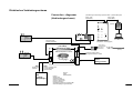
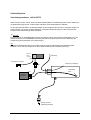
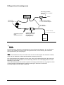
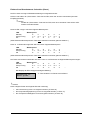
Elektrisches Verbindungsschema
The sequence of these connections can be changed as required (parallel bus system)
(Die Reihenfolge der Verbindungen spielt keine Rolle --> paralleles Bussystem)
"phone"- cable
"phone"- cable
("Telefonkabel")
("Telefonkabel")
Connection - diagramm
(Verbindungsschema)
Jet-tronic
(optional)
Remote - GSU
-
+
+
Standby / Man.
RS232
Adapter
Ignition on
Pump running
OK / Reset...
LED I/Oboard
Shut-off
valve
propane
Info
Min/Max
Run
Limits
Manual
Ignition
Change
Value
Item
Select
Menu
PC
GSU =ground support unit
(Programmier- und Anzeigegerät)
6-wire phone cable
6-adriges Telefonkabel
ECU top-view
(von oben)
+ -
Shut-Off
valves
THR
Throttle stick
(Gaskanal)
-
AUX
linked to a 3 position switch
on the RC-transmitter
(3-Stufenschalter)
RC
receiver
(Empfänger)
Receiverbattery
(Empfängerakku)
ReceiverON/OFF switch
(Empfängerschalter)
The ECU is automatically
powered up whenever the
receiver is switched on
(Die Elektronik schaltet sich automatisch EIN
sobald der Empfänger eingeschaltet wird)
Temp.&Rpm
Sensor
(connect to turbine)
+
V2.0
air pressure
(Staudruck)
(optional)
6-wire phone cable to turbine
6-adriges Telefonkabel, zur Turbine
+
Smoker
Fuel
Fuzzylogic
6 Cells
Microcomputer-Control
Battery : 7,2V
Data-BUS
Shut-off
valve
fuel
-
Jet-tronic -II- P80
Airspeed
Propane
static pressure
(statischer Druck)
Airspeed
Sensor
NiCad
battery (6 cells)
pitot-tube
(Staurohr)