1
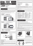
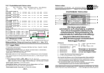
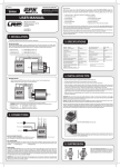
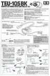
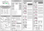
Hacker Motor GmbH Schinderstraßl 32 Tel.: 0049 (0) 871-953628-0 Fax.:0049 (0) 871-953628-29 [email protected] D-84030 Ergolding ANSCHLUSS VON REGLER UND AKKU EINSTELLUNGSMÖGLICHKEITEN Verbinden Sie ihren Akku über den DEAN-T Stecker mit dem Regler. Prüfen Sie vor dem ersten Anschluss ihre Verkabelung! Betriebsmodus WARNUNG! Ein verpolter Anschluss ihres Akkus zerstört ihren Regler! 1. “Vorwärts/Bremse” ist für den Wettbewerbseinsatz geeignet. In diesem Modus können Sie nur vorwärts fahren und bremsen. Die Rückwärtsfahrt ist nicht möglich. REGLERKALIBRIERUNG Bedienungsanleitung für TENSORIC SC Fahrtenregler Herzlich Willkommen im Team! Der TENSORIC SC Brushless-Fahrtenregler verwendet die aktuellste Technologie. Unsere R&D Abteilung hat zusammen mit dem Testteam unzählige Stunden damit verbracht, diesen Regler zu optimieren. Ein einfaches Handling, sowie optimales Regelverhalten zeichnen den TENSORIC SC aus. EIGENSCHAFTEN • Entwickelt für On-Road und Off-Road Einsatz • Hoch präzises Regelverhalten • Integriertes Hochleistungs-BEC System für konstante Stromversorgung von Servo und Empfänger • Einfachstes Setup mit Setup-Taste oder optionaler Programmierbox • Vorwärts- und Rückwärts-Funktion • Diverse einstellbare Parameter (siehe Zusatzblatt) • Multi-Schutz-System: Akku-Abschaltspannung, Überhitzen, Signalverlust, blockierter Motor Damit ihr TENSORIC 8 korrekt funktioniert müssen Sie diesen auf ihre Fernsteuerung abstimmen. Um mit der Reglerkalibrierung zu beginnen, setzen Sie alle Parameter an ihrer Fernsteuerung zurück. Befolgen Sie diese Schritte, um den Regler zu kalibrieren 1. Schalten Sie den Regler aus und die Fernsteuerung ein. 2. Stellen Sie die Gas-Trimmung auf neutral und den Ausschlag auf 100%. Deaktivieren Sie Spezialfunktionen wie ABS etc. 3. Drücken und halten Sie die “SET”-Taste (auf dem Ein-/Aus-Schalter) und schalten Sie den Regler ein. 4. Lassen Sie die “SET”-Taste los, sobald am Regler die LED rot blinkt. 5. Stellen Sie die folgenden Positionen am Sender ein und bestätigen Sie jeweils mit der “SET”-Taste: o o o VORSICHTSMASSNAHMEN & WARNUNGEN Lesen Sie diese Anleitung vor dem Einsatz ihres neuen TENSORIC SC sorgfältig durch! Vermeiden Sie eine falsche Übersetzung indem Sie immer wieder die Motor- und ReglerTemperatur überprüfen. Achten Sie darauf, dass die Motortemperatur 80°C und die Regler-Temperatur 90° nicht übersteigt.. MONTAGE 6. Der Motor piept nach dem letzten Schritt für 3 Sekunden. Danach ist der Vorgang abgeschlossen. 7. Schalten Sie ihren Regler aus. FUNKTION DER STATUS LED Bei der Montage ist darauf zu achten, dass sie den Regler so positionieren, dass dieser möglichst geschützt positioniert wird. Achten Sie darauf, dass Sie nach dem Einbau möglichst einfach an den Schalter, sowie SetKnopf des Reglers kommen. Nach dem Einbau dürfen keinerlei Kabel an freistehenden Wellen, oder Zahnrädern schleifen. Versuchen Sie stromführende Komponenten vom Empfänger so weit wie möglich entfernt einzubauen. Der TENSORIC SC ist auf der Motorseite mit drei 4mm Goldkontaktbuchsen für den Motoranschluss bestückt. Für den Anschluss der Fahrakkus haben wir am Regler zwei 4mm Goldkontaktbuchsen angebracht. ANSCHLUSS VON REGLER UND MOTOR Stecken Sie ihren TENSORIC SC auf den Gaskanal (meist Kanal 2) am Empfänger Verbinden Sie den Regler mit ihrem Motor wie folgt: • • • Neutralpunkt (LED blinkt 1 mal) Vollgas (LED blinkt 2 mal) Vollbremse/rückwärts (LED blinkt 3 mal) Regler: Kabel A Motor: Anschluss A Regler: Kabel B Motor: Anschluss B Regler: Kabel C Motor: Anschluss C Sensorless Brushless Motoren Sollten Sie den TENSORIC 8 ohne Sensor verwenden, so ist die Reihenfolge der Verkabelung prinzipiell egal. Um für einen Sensorbetrieb gerüstet zu sein, empfehlen wir trotzdem, die Reihenfolge der A-B-C Kabel einzuhalten. Sollte ihr Motor die falsche Drehrichtung aufweisen, so vertauschen Sie einfach zwei beliebige Motorkabel. Sensor Brushless Motor Der TENSORIC 8 mit seiner „softsensored“-Technologie, erkennt automatisch den Anschluss eines Sensors-Motors! Halten Sie die Reihenfolge der A-B-C Kabel unbedingt ein, die Drehrichtung ihres Motors können sie mit Hilfe der Software oder der optional erhältlichen PROGBOX umstellen. In Neutralposition leuchtet keine LED Die LED am Regler leuchtet rot, wenn das Fahrzeug bremst, oder vorwärts/rückwärts fährt. Bei Vollgas leuchtet die LED grün. WARNTÖNE 1. 2. Problem mit Eingangsspannung: Der Regler prüft die Eingangsspannung, sobald er eingeschaltet ist. Wenn ein Problem erkannt wird, ertönen wiederholt zwei Signaltöne im Abstand von einer Sekunde (xx-xx-xx). Problem mit dem Empfangssignal: Der Regler prüft das Empfangssignal, sobald er eingeschaltet ist. Falls ein Problem besteht, ertönt wiederholt ein Signalton im Abstand von zwei Sekunden (x-x-x). ERWEITERTE EINSTELLUNGEN Sie können mit der Setup-Taste, oder mit der zusätzlichen Hacker PROGBOX diverse erweiterte Einstellungen vornehmen. Um eine Einstellung mit der Setup -Taste zu verändern, befolgen Sie die folgende Anleitung (siehe auch Bild auf Zusatzblatt) 1. Schalten Sie den Regler ein Automatik-Bremse Bremst das Fahrzeug automatisch ab, wenn der Gashebel in die Neutralposition geführt wird. Dies simuliert die Motorbremse eines echten Fahrzeugs. Akku-Abschaltspannung Diese Funktion dient dazu, eine Tiefentladung des Akkus zu verhindern. Achtung moderne Akku benötigen eine höhere Abschaltspannung, da sie aufgrund ihrer Entladekurve sehr schnell Tiefentladen werden! Der Regler prüft die Akku-Spannung fortlaufend. Fällt die Spannung unterhalb den angegebenen Wert für 2 Sekunden, oder mehr, wird die Ausgangsleistung gestoppt und die rote LED leuchtet wiederholt 2 mal. Das eingestellte Limit ist abhängig von der individuellen Zellspannung. Startmodus Diese Einstellung ermöglicht es, die Beschleunigungscharakteristik des Fahrzeugs zu verändern. Level 1 ergibt eine sehr feine Beschleunigung und Level 9 beschleunigt sehr stark aus dem Stand. Diese Funktion ist von der Wirkung her wie die Exponentialfunktion an der Fernsteuerung. Bei den Levels 7, 8 und 9 sind Hochleistungsakkus zwingend Notwendig, um eine Überlastung des Akkus, schlechte Leistung oder unvorhergesehene Komplikationen zu vermeiden. Maximale Bremskraft Diese Einstellung betrifft die maximale Bremskraft des Reglers. Ein höherer Wert führt zu stärkerer Bremskraft. Maximale Rückwärts-Leistung Diese Einstellung stellt die maximale Leistung für die Rückwärtsfahrt ein. Minimalbremskraft Mit dieser Einstellung können Sie die minimale Bremskraft beim Betätigen der Bremse verändern. Der Minimalwert dieser Einstellung ist mit dem Wert der Automatik-Bremse identisch kann aber auch individuell eingestellt werden. Neutral-Bereich Diese Einstellung betrifft die Empfindlichkeit des Regelverhaltens um den Neutralpunkt. Timing Diese Einstellung verändert das Timing des Motors. Mehr Timing ergibt mehr Leistung, doch kann die Effizienz verringert werden und den Motor oder Regler beschädigen. Motor Drehrichtung 3. Betätigen Sie die Setup-Taste noch einmal. LiPo-Zellenzahl 4. Die grüne LED blinkt wiederholt 1 mal. Dies zeigt an, dass die Einstellung 1 gewählt ist. Der TENSORIC 8 besitzt eine Automatik-Erkennung für die Zellenanzahl ihres Akkus. Mit dieser Einstellung überschreiben Sie den Wert der automatisch erkannt wurde und geben manuell die Zellenanzahl ihres Fahrakkus an. 5. Betätigen Sie die Set-Taste 1 mal kurz, gelangen Sie zu Einstellung 2 usw. bis Sie durch alle Einstellungen geblättert haben, danach kommt erneut Einstellung 1. 6. Um eine Einstellung zu ändern, drücken und halten Sie (bei der gewünschten Einstellung) die Setup-Taste für 3 Sekunden. Verbinden Sie den Regler mit ihrem Motor wie folgt: 7. Die rote LED wird nun den Wert der Einstellung anzeigen: blinkt sie einmal, so beträgt der Wert 1, blinkt sie 2 mal, beträgt der Wert 2 usw. Regler: Kabel A Motor: Anschluss A Regler: Kabel B Motor: Anschluss B Regler: Kabel C Motor: Anschluss C 3. “Vorwärts/Rückwärts” ist für Rock Crawler geeignet. Dieser Modus hat keine Bremse. Das Fahrzeug kann zudem direkt von Vorwärts- zu Rückwärtsfahrt wechseln. Verwenden Sie diesen Modus nicht mit anderen Autos, da der Fahrtenregler sonst beschädigt werden kann. 2. Betätigen und halten Sie die Setup-Taste für eine Sekunde, bis die grüne LED zu blinken beginnt. Danach lassen Sie die Taste los (beim Halten der “SET”-Taste für 5 Sekunden wird der Regler auf die Standardeinstellungen zurückgesetzt) WARNUNG! Wenn Sie einen Motor mit Sensor verwenden, müssen Sie auf die korrekte Reihenfolge der AB-C Kabel achten. • • • 2. “Vorwärts/Rückwärts mit Bremse” ist der Modus für den Allround-Einsatz. Ihr Fahrzeug kann damit vorwärts und rückwärts fahren. Wenn Sie den Gashebel während der Vorwärtsfahrt auf Rückwärtsposition stellen, bremst das Fahrzeug bis zum Stillstand. Es ist nicht möglich, den Motor rückwärts drehen zu lassen, bevor das Fahrzeug zum Stillstand gekommen ist. Wenn Sie rückwärts fahren wollen, müssen Sie den Gashebel nach der Vollbremsung wieder auf die Neutralposition bewegen, bevor Sie ihn zur Rückwärtsfahrt wieder auf Rückwärtsposition bringen. 8. Drücken Sie die Set-Taste, um den Wert zu verändern. 9. Wenn Sie den gewünschten Wert eingestellt haben, drücken und halten Sie die Set -Taste für 3 Sekunden, um die Änderung zu speichern. 10. Schalten Sie den Regler aus und wieder ein, um die neue Einstellung zu aktivieren. Bitte beachten: Sie können jeweils nur eine Einstellung verändern. Nach jeder Veränderung muss der Regler ein- und ausgeschaltet werden. Diese Einstellung erlaubt es, die Drehrichtung des Motors zu ändern. Auf Werkseinstellungen zurücksetzen Drücken und halten Sie die “SET”-Taste 5 Sekunden lang (Gashebel in Neutralposition): die rote und grüne LED beginnen gleichzeitig zu blinken, sobald alle Werte auf die Werkseinstellung zurückgesetzt worden sind. SOFTWARE UPDATE Die stätige Weiterentwicklung führt auch zu Verbesserungen der Reglersoftware. Eine aktualisierte Firmware für ihren TENSORIC 8 Fahrtenregler finden Sie auf unserer Webseite: www.hacker-motor.com, oder auf unserer CARLINE-Webseite www.hacker-carline.de Für die Aktualisierung ihres Fahrtenreglers benötigen Sie die Hacker PROGBOX als Interface. EINSTELLUNGEN / PROGRAMMIERUNG Bitte beachten Sie die Zusatzinformationen am Ende dieser Bedienungsanleitung. TECHNISCHE DATEN KONFORMITÄTSERKLÄRUNG Für die in dieser Anleitung erwähnten Produkte aus unserem Hause gilt die einschlägige und zwingende EG Richtlinie: Daten WARNUNGEN & HINWEISE o o o o o Dieser Regler ist kein Spielzeug! Lassen Sie Kinder beim Gebrauch dieses Produkts nie unbeaufsichtigt. Lassen Sie den Regler nie unbeaufsichtigt im eingeschalteten Zustand. Der Regler darf im Bereich von brennbaren Materialien nicht verwendet werden! Sollte der Regler nicht richtig funktionieren, ziehen Sie sofort den Akku ab und kontaktieren Sie den Fachhandel. Der Regler muss immer Stromlos gelagert werden – nach dem Gebrauch immer Akku abstecken! Best.-Nr. 71900110 Konstantstrom 100A Max. Strom 520A Innenwiderstand 0,0007 Ohm Funktionen Forwärts/Bremse Forwärts/Bremse/Rückwärts Forwärts/Rückwärts Folgende Fachgrundnormen wurden herangezogen: ALLG. GEWÄHRLEISTUNGSBESTIMMUNGEN Produkte der Hacker Motor GmbH werden nach strengsten Qualitätskriterien gefertigt. Wir gewähren die gesetzliche Gewährleistung auf Produktions- und Materialfehler, die zum Zeitpunkt der Auslieferung des Produkts vorhanden waren. Für gebrauchstypische Verschleißerscheinungen wird nicht gehaftet. Diese Gewährleistung gilt nicht für Mängel, die auf eine unsachgemäße Benutzung, mangelnde Wartung, Fremdeingriff, oder mechanische Beschädigung zurückzuführen sind. Dies liegt unter Anderem vor bei: o Stecker abgeschnitten oder Anbringen eines nicht Verpolungssicheren Stecksystems o Empfängerkabel und/oder Schalter beschädigt o mechanische Beschädigung, oder Zerstörung des Gehäuses o Wasser oder Wasserrückstände im Gehäuse o Mechanische Beschädigung der Bauteile und / oder der Platine o Auf der Platine gelötet (Ausnahme außen liegende Lötsockeln) o Akkuseitig verpolt Bevor Sie dieses Produkt zur Reparatur einsenden, prüfen Sie bitte zunächst alle anderen Komponenten um andere Störquellen und Bedienfehler auszuschließen. EMV-Richtlinie: 2004/108/EG Akkutyp 2-3S LiPo/LiFe 6-9S NiMh BEC 6V max. 3A LxBxH 53,6x36,36 Gewicht 74g ohne Kabel FEHLERSUCHE S = Symptom P = Problem L = Lösung S: Regler eingeschaltet, jedoch keine Funktion des Motors und keine Signaltöne. EN 61000-6-1:2007 EN 61000-6-3:2007 Ergolding, 04.02.2012 Benutzerinformationen zur Entsorgung von elektrischen Geräten und elektronischen Geräten (privater Haushalt) Entsprechend der grundlegenden Firmengrundsätzen wurde ihr Produkt aus hochwertigen Materialien hergestellt, die recyclebar und wieder verwendbar sind. P: Problem mit Akkuanschluss, oder Ein-/Ausschalter L: Überprüfen Sie ihre Verbindung zum Akku, sowie ihren Schalter REPARATURBESTIMMUNGEN S: Regler eingeschaltet, keine Motorfunktion, zwei Reglersignal mit Pause von einer Sekunde Mit der Einsendung des Produktes muss der Kunde mitteilen, ob das Produkt in jedem Fall repariert werden soll. Sollte kein Gewährleistungs- oder Garantieanspruch bestehen, erfolgt die Produktüberprüfung und ggf. Reparatur in jedem Falle kostenpflichtig gemäß unserer Preisliste. Ein Gewährleistungs- oder Garantieanspruch kann nur anerkannt werden, sofern eine Kopie des Kaufbelegs beigefügt ist. Auf Anforderung erstellen wir gerne ein kostenpflichtiges Reparaturangebot. An unser Reparaturangebot sind wir zwei Wochen ab Ausstellungsdatum gebunden. Bei Beauftragung der Reparatur werden die Kosten für das Reparaturangebot nicht berechnet. Für eine schnelle Abwicklung Ihres Servicefalls legen Sie bitte eine ausführliche Fehlerbeschreibung und ihre Adressdaten der Einsendung bei. P: Eingangsspannung zu hoch, oder zu niedrig L: Überprüfen Sie ihren Akku S: Regler eingeschaltet, keine Motorfunktion, rote LED leuchtet P: Empfangssignal gestört L: Überprüfen Sie ihre Fernsteuerung und ihren Empfänger, sowie den Anschluss ihres Reglers am Empfänger. S: Motor dreht in die falsche Richtung P: Motor falsch angeschlossen, oder Regler nicht richtig eingestellt L: Bei sensorlosem können Sie zwei Kabel am Motor vertauschen, oder wechseln Sie die Motordrehrichtung mittels der Regler-Software Dieses Symbol auf Produkten und/oder begleitenden Dokumenten bedeutet, dass elektrische und elektronische Produkte am Ende Ihrer Lebensdauer vom Hausmüll getrennt entsorgt werden müssen. Bringen Sie bitte diese Produkte für die Behandlung, Rohstoffrückgewinnung und Recycling zu den eingerichteten kommunalen Sammelstellen bzw. Wertstoffsammelhöfen, da diese Geräte kostenlos entgegennehmen. Die Ordnungsgemäße Entsorgung dieses Produkts dient dem Umweltschutz und verhindert mögliche schädliche Auswirkungen auf Mensch und Umwelt, die sich aus einer unsachgemäßen Handhabung der Geräte am Ende ihrer Lebensdauer ergeben könnten. Genauere Informationen zur nächstgelegenen Sammelstelle bzw. Recyclinghof erhalten Sie bei Ihrer Gemeindeverwaltung. S: Motor stoppt plötzlich P: Akkuabschaltung, oder Überhitzungsschutz aktiv L: Beachten Sie die Regler LED! Blinkt diese rot ersetzen, oder laden Sie ihren Akku. Blinkt die LED an ihrem Regler grün, so lassen Sie ihr System abkühlen und überprüfen Sie ihr System auf Kühlung, Übersetzung, oder Defekte. Für Geschäftskunden in der Europäischen Union Bitte treten Sie mit Ihrem Händler oder Lieferanten in Kontakt, wenn Sie elektrische und elektronische Geräte entsorgen möchten. Er hält weitere Informationen für Sie bereit. Informationen zur Entsorgung in Ländern außerhalb der Europäischen Union. Dieses Symbol ist nur in der Europäischen Union gültig. S: Motor unterbricht Funktion, oder stottert bei der Beschleunigung P: Akku-Leistung zu gering, oder Untersetzung zu groß L: Wechseln Sie auf einen stärkeren Akku, oder tauschen Sie ihren Motor gegen einen Leistungsärmeren aus. Oftmals genügt eine andere Untersetzung. Überprüfen Sie auch ihre Einstellungen am Regler. Hacker Motor GmbH Schinderstraßl 32 D-84030 Ergolding Tel: +49 871-953628-0 Fax: +49 871-953628-29 E-Mail: [email protected] Copyright ©, Hacker Motor GmbH 2012 Irrtum und Änderungen vorbehalten WEEE-Reg.-Nr. DE 55352581 Copyright©2012 Hacker Motor GmbH. All rights reserved. Hacker Motor GmbH Schinderstraßl 32 D-84030 Ergolding Tel.: 0049 (0) 871-953628-0 Fax.:0049 (0) 871-953628-29 [email protected] CONNECTION OF CONTROLLER AND BATTERY SETTING OPTIONS Connect the battery via the DEAN-T plug with the controller. Check the wiring before first use! Explanation for each programmable item Attention! A reverse polarity connection of your batteries will destroy the controller! CONTROLLER CALIBRATION Manual for TENSORIC SC electronic speed control In order to ensure a proper function of your controller you have to adjust your controller to your transceiver. To start with the calibration please reset all functions on your transceiver. Welcome to the team! Please follow the steps below to calibrate your controler The TENSORIC SC Brushless electronic speed control is driven by the latest technology. Our R&D department has spent hours and hours together with our drivers-team to optimize this controller. Easy handling and optimal control behavior is characterized by the TENSORIC SC. FEATURES: • Developed for On-Road and Off-Road use • High precision control behavior • Integrated high end BEC-System for linear supply of servo and receiver • Easy setup with Setup button or optional programming box • Forward – break – backward function • Several programmable parameters ASSEMBLY Turn off your controller and transceiver. 2. Set your throttle trim on neutral and the range at 100%. Reactivate special functions like ABS eg. 3. “Forward/Reverse” mode uses “Single-click” method to make the car go backward. When you move the throttle stick from forward zone to backward zone, the car will go backward immediately. This mode is usually used for the Rock Crawler. 3. Push and hold the “SET”-button (located at the on/off switch) and turn on the controller. Drag Brake Force: 4. Release the “SET”-button as soon as the LED is flashing red. Set the amount of drag brake applied at neutral throttle to simulate the slight braking effect of a neutral brushed motor while coasting. 5. Set the following positions on your transceiver and confirm with the "SET" button: Low Voltage Cut-Off: o o o The TENSORIC SC is equipped with 4mm gold contact on the motor output side. . CONECTION OF CONTROLLER AND MOTOR 6. The Motor will quit with a beep for 3 seconds after the last step. Then you have succesfully finished. 7. Turn off your controller. Normally, if the throttle stick is in the neutral range, neither the red LED nor the green LED lights. The red LED lights when the car is running forward or backward and it will flash quickly when the car is braking. The green LED lights when the throttle stick is moved to the top point of the forward zone. ALLERT TONES 1. Connect the TENSORIC SC to your throttle channel (mostly channel 2) on your receiver. Connect motor and controller as follows: • • • Neutral (LED flashing 1 time) Full throttle (LED flashing 2 times) Full break/backwards (LED flashing 3 times) CHECK THE LED STATUS IN NORMAL RUNNING When mounting, ensure that the position of the controller is in a way that it is protected. Make sure that you have after the installation an easy as possible access to the switch, as well as setup button of the controller. Please ensure that after installation, no cables can drag on free-standing shafts, or gears. Try to place electrical components eg. receiver away from the controller as far as possible. controller: cable A motor: connection A controller: cable B motor: connection B controller: cable C motor: connection C Sensored brushless motor wiring When using brushless motor with Hall Sensor,it is necessary to connect the sensor cable to the “ SENSOR” port on the ESC, and ESC can automatically identify the motor type (sensored or sensorless) by detecting the signal coming from the SENSOR port. 2. “Forward/Reverse with Brake” mode uses “Double-click” method to make the car go backward. When you move the throttle stick from forward zone to backward zone for the 1st time (The 1st “click”), the ESC begins to brake the motor, the motor speeds down but it is still running, not completely stopped, so the backward action is NOT active immediately. When the throttle stick is moved to the backward zone for the 2nd time (The 2nd “click”), if the motor speed is slowed down to zero (i.e. stopped), the backward action will happen. The “DoubleClick” method prevents mistaken reversing action when the brake function is frequently used in steering. By the way, in the process of brake or reverse, if the throttle stick is moved to forward zone, the motor will run forward at once. 1. PRECAUTIONS & WARNINGS Read these instructions carefully before using your new TENSORIC SC! Avoid using a wrong gear ratio by continuously monitoring the motor and controller temperature. Make sure that the motor temperature does not exceed 80 ° C and the controller temperature does not exceed 90 °C. 1. “Running Mode” with “Forward with Brake” mode, the car can go forward and brake, but cannot go backward, this mode is suitable for competition; “Forward/Reverse with Brake” mode provides backward function, which is suitable for daily training. 2. Input voltage abnormal alert tone: The ESC begins to check the input voltage when powered on, if the voltage is out of the normal range, such an alert tone will be heard: “beep-beep-, beep-beep-, beep-beep-” (There is 1 second interval between every group of “beep-beep-” tone). Throttle signal abnormal alert tone: When the ESC can’t detect the normal throttle signal, such an alert tone will be heard: “beep-, beep-, beep-” (There is 2 seconds interval between every “beep-” tone). ADVANCED SETTINGS By using the setup – button or the Hacker PROGBOX it is possible to have some advanced setups. Please follow the steps below: Further information you will find at the end of the manual. The function prevents the lithium battery pack from over discharging. The ESC detects the battery’s voltage at any time, if the voltage is lower than the threshold for 2 seconds, the output power will be reduced 70%, after 10 seconds the output will be completely stopped, and the red LED flashes in such a way:“☆-☆-, ☆-☆-, ☆-☆-”. There are 6 preset options for this item. You can customize the cutoff threshold by using an advanced LCD program box (optional equipment) to trim it with a step of 0.1V, so it will be more suitable for all kinds of batteries (NiMH, NiCd, Li-ion, Lipo, LFP,etc). Please always keep in mind that the customized value is not for each cell, it is for the WHOLE battery pack. Start Mode: Select from “Level1” to “Level9” as you like, Level1 has a very soft start effect, while level9 has a very aggressive start effect. From Level1 to Level9, the start force is increasing. Please note that if you choose “Level7” to “Level9” mode, you must use good quality battery pack with powerful discharge ability, otherwise these modes cannot get the burst start effect as you want. If the motor cannot run smoothly (the motor is trembling), it may caused by the weak discharge ability of the battery pack, please choose a better battery or increase the gear ratio (Use a smaller pinion). Maximum Brake Force: The ESC provides proportional brake function. The brake force is related to the position of the throttle stick. Maximum brake force refers to the force when the throttle stick is located at the top point of the backward zone. A very large brake force can shorten the brake time, but it may damage the gears. The “Disable” option inhibits the inherent brake function of the speed controller. When this option is selected, the brake function is realized by a traditional disc-brake system driven by a servo. Maximum Reverse Force: Sets how much power will be applied in the reverse direction. Different value makes different reverse speed. Initial Brake Force: It is also called “minimum brake force”, and it refers to the force when the throttle stick is located at the initial position of the backward zone. The default value is equal to the drag brake force, so the brake effect can be very smoothly. Sensorless brushless motor wiring When using brushless motor without Hall Sensor, the #A, #B, #C wires of the ESC can be connected with the motor wires freely (without any sequence). If the motor runs in the opposite direction, please swap any two wire connections. 1. Switch on the controller WARNING! For sensored brushless motor, the #A, #B, #C wires of the ESC MUST be connected with the motor wire #A, #B, #C respectively. Do not change the wires sequence optionally! 3. Push the setup – button once again. This setting affects the sensitivity of the control response around neutral. 4. The green LED is flashing a single signal to identicate the setting 1. Timing 5. To rotate through the advanced setup menu push the setup button again shortly 7. The red LED display is now the value of the setting: LED blinks 1 time, for the value 1, LED blinks 2 times, the value 2, etc. The “timing” item is usable for both sensored and sensorless brushless motors. There are many differences among structures and parameters of different brushless motors, so a fixed timing ESC is difficult to comparate with all brushless motors. It is necessary to make the timing value programmable. Please select the most suitable timing value according to the motor you are just using. Generally, higher timing value brings out higher power output, but the whole efficiency of the system will be slightly reduced. 8. Press the Set button to change the value. Motor Rotation: 9. If you have set the desired value, press and hold the Set button for 3 seconds to save the change. You can use this item to change the rotation direction. Face to the motor shaft (That means the rear cover of the motor is far from your face), and move the throttle stick to the top point of the forward zone. If this item is set to “CCW”, the shaft runs counter-clockwise; If this item is set to “CW”, the shaft runs clockwise. 2. Push and hold the setup-button, until the green LED is flashing. Release the setup – button as soon as the LED is flashing green 6. To change a setting, press and hold (at the desired setting), the setup button for 3 seconds. 10. Switch off the controller in order to activate the new setup Please note: You can chance only one setting at the time. After every single change you have to switch off and switch on the controller Neutral-Range Lipo Cells: MAIN APPLICATIONS We strongly suggest setting the “Lipo Cells” item manually. Because the normal voltage of each Lipo cell varies from 2.6V to 4.2V, it is quite difficult to calculate the cells number of a discharged Lipo battery pack. If it is calculated incorrectly, the Low Voltage Cutoff Protection function may work abnormally, so the option “Auto Calculate” is only available for 2s, 4s and 6s Lipo. If the voltage of the battery pack is lower than 8.8V, it is judged as a 2s Lipo; If the voltage is between 8.8V to 17.6V, it is judged as a 4s Lipo; If the voltage is higher than 17.6V, it is judged as a 6S Lipo. So in order to make the Low Voltage Cutoff Protection function correctly, please set the “Lipo Cells” item manually. Software update: The continuous development of our team also leads to improvements in the control software. An update of the firmware for the TENSORIC 8 ESC is available on our Website: www.hackermotor.com. For updating of the controller you need the Hacker PROGBOX as an interface. For the products manufactured by Hacker Motor GmbH mentioned in this manual the compelling and relevant EC Directive will apply: Data Order-Nr. 71900110 Constant current 100A Max. current 520A Internal resistance 0,0007 Ohm Function Foreward/Brake Foreward/Brake/Backward Foreward/Backward Battery typ 2-3S LiPo/LiFe 6-9S NiMh BEC 6 V max. 3A LxBxH 53,6x36,36 mm Weight 74g without cable EMV-Directive: 2004/108/EG Reset All Items To Default Values: At any time when the throttle is located in neutral zone (except in the throttle calibration process or ESC program mode), hold the “SET” key for over 3 seconds, the red LED and green LED will flash at the same time , which means each programmable item has be reset to its default value. DECLARATION OF CONFORMITY The following special directives will apply: EN 61000-6-1:2007 EN 61000-6-3:2007 Ergolding, 04.02.2012 SETTING / PROGRAMMING Please refer to the additional information at the end. WARNINGS & INFORMATIONS o o o o o This controller is not a toy! Do not leave children unattended when using this product. Do not leave the controller unattended when switched on. The controller may not be used in the range of combustible materials! If the controller does not work properly, disconnect the battery immediately and contact the dealer. The controller must always be stored without a battery connected - Disconnect the battery immediately after use! GERNERAL WARRANTY PROVISIONS TROUBLE SHOOTING T = Trouble P = Possible Reason S = Solution T: After power on, motor doesn’t work, and the cooling fan doesn’t work P: The connections between battery pack and ESC are not correct S Check the power connections / Replace the connectors Hacker Motor GmbH products will be manufactured in accordance with the highest quality criterias. We provide the legal guarantee, to be free of defects on material and workmanship. There will be no liability for typical use sign of wear. The warranty does not cover defects which are a result of misuse, improper maintenance, or mechanical damage. T: After power on, motor can’t work, but emits “beep-beep-, beep-beep-” alert tone. (Every group of “beep-beep-” has a time interval of 1 second ) This is among other things on: o connector cut off or placing a non-polarized connector system o switch wire damaged o mechanical damage, or destruction of the housing o water or residual water in the housing o Mechanical damage to the electronic components and / or the board o soldered on the PCB (except on external soldering sockets) o Battery polarity reversed T: After power on, red LED always lights, the motor doesn’t work Before returning your product for repair, please check all other components in order to avoid any operator error. . REGULATIONS FOR REPAIR By returning of the product, the customer, should identify whether the product will be repaired in any case or not. In the case that no warranty or guarantee applies, the product testing and possible repair or service will be charged according to our price list. A guarantee or warranty can only be accepted if a copy of your receipt is attached. On request, we will offer you a repair quote. On our repair quote, we are bound for two weeks from the date of issue. By carrying out the repair the cost for the repair quote will not be charged. For quick repair and return service, please provide a detailed description of the failure and full address details. Information for Users on disposal of electrical equipment and electronic equipment (private households) According to the basic business principles, your product is made from high quality materials, which are recyclable and reusable. P: Input voltage is abnormal, too high or too low S: Check the voltage of the battery pack P: Throttle signal is abnormal S: Plug the control wire into the throttle channel of the receiver correctly. This symbol on the products and / or accompanying documents means that used electrical and electronic products must be at the end of their lifetime separated from household waste. Please take these products for the treatment, recovery and recycling to designated collection points, which will receive the devices free of charge. The Proper disposal of this product, prevent any potential adverse effects on humans and the environment which could otherwise arise from inappropriate waste handling at the end of its lifetime. For more precise details of your nearest designated collection point, contact your local authority. T: The motor runs in the opposite direction when it is accelerated P: The wire connections between ESC and the motor are not correct S: 1) For sensorless motor: Swap any two wire connections between the ESC and the motor. Or use the method #2 2) For sensored motor: Please check the wire connections, they must be A-A, B-B, C-C respectively. If the connections are correct, please change the “Motor Rotation” programmable item to “CW(Clockwise)” For business users in the European Union Please contact your dealer or supplier for further information if you wish to dispose electrical and electronic equipment. He holds further information ready for you. Information on Disposal in other Countries outside the European Union. This symbol is only valid in the European Union. T: The motor suddenly stops running while in working state P: The throttle signal is lost or the ESC has entered the Low Voltage Protection Mode or Overheat Protection Mode S: Check the transmitter and the receiver Check the signal wire from the throttle channel of your receiver or Red LED flashing means Low voltage protection. Green LED flashing means Over-heat protection T: When accelerating quickly, the motor stops or trembles P: 1) The battery has a bad discharge performance 2) The gear rate is too small 3) The “Start Mode (Punch)” of the ESC is too aggressive S: 1) Use a better battery 2) Use lower KV motor or change the gear rate, choose smaller pinion 3) Select a softer option for the “Start Mode (Punch)” Hacker Motor GmbH Schinderstraßl 32 D-84030 Ergolding Tel: +49 871-953628-0 Fax: +49 871-953628-29 E-Mail: [email protected] Copyright ©, Hacker Motor GmbH 2012 Irrtum und Änderungen vorbehalten WEEE-Reg.-Nr. DE 55352581 T: When the throttle stick is in the neutral range, the red LED and the green LED flashes synchronously P: The motor is a sensored motor, but the ESC detects abnormal signal from the sensor, so it changes to sensorless mode automatically S: 1) Check the connection of Hall sensor cable to make it firmly connect the motor with the ESC 2) The Hall sensors in the motor are damaged, please change the motor Copyright© 2012 Hacker Motor GmbH. All rights reserved. Hacker Motor GmbH Schinderstraßl 32 D-84030 Ergolding Tel.: 0049 (0) 871-953628-0 Fax.:0049 (0) 871-953628-29 [email protected] TENSORIC ESC ADITIONAL INFORMATIONEN: CALIBRATION: Push Set-Button Throttle neutral Throttle full foreward Throttle full brake Switch on Pusch SET Pusch SET Pusch SET LED blincs 4 red LED blincs 1 green LED blincs 2 green LED blincs 3 green WORKFLOW – PROGRAMMING WITH SET-TASTE: PROGRAMABLE PARAMETERS: Grau = Standardeinstellung Hacker Motor GmbH Schinderstraßl 32 D-84030 Ergolding Tel: +49 871-953628-0 Fax: +49 871-953628-29 E-Mail: [email protected] Copyright ©, Hacker Motor GmbH 2010 Irrtum und Änderungen vorbehalten WEEE-Reg.-Nr. DE 55352581 Copyright 2012 Hacker Motor GmbH. All rights reserved.