1
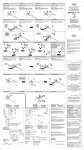
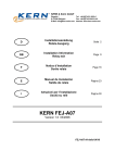
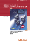
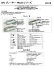
User ’s Manual No.99MAG009M3 SERIES No.7200 デプスゲージ(ダイヤルタイプ、デジタルタイプ) はじめに ご使用になる前に必ず 「 ユーザーズマニュアル 」 をお読みの上、正しくお使い下さい。お読みになった後は、いつでも見られる所に必ず保管して下さい。 7. リミット針の取り付け、取り外し ( ダイヤルタイプ ) <取り付け> リミット針 1. 安全上のご注意 リミット針を取り付ける前に、 リミット針を分離して下さい。 (7231のみ) ・この表示を無視して、誤った取り扱いをすると、人が障害を負う可能性が想定される内容および物的損害のみの発生が想定されることを示 しています。 <取り外し> ② ① 注意 2. 各種の注意について 重要 ・目的を達成するために必要な情報を示す注記です。 外枠 ① ・この指示に従わない場合、本器の性能を損なう可能性あるいは維持することが困難になる可能性があることを示します。 ケガをしないように 注意 ご注意下さい。 注記 ・本文の重要な点で、特に強調または補足すべき情報や特定の操作に関してご留意頂きたい事柄があることを示します。 3. 使用環境 <取り付け> ①アリ溝にはめ込みます。 ②クランプネジを締め込みます。 ・急激な温度変化を避けて下さい。結露して性能に悪影響を及ぼすことがあります。 ・塵埃や油、オイルミストが少ない場所で使用して下さい。 ・直射日光の当たらない場所で使用して下さい。 ストップネジ ※図の外観は一例です。 継足ロッドを使用する場合の基準点の合わせ方 スペーサー <取り付け> ①スピンドルを持ち上げて、リフティン グレバーの先端をストップネジにはめ 込みます。 このとき、スペーサーの下にリフティ ングレバーの先端を入れて下さい。 ②アリ溝にリフティングレバーの溝をは め込み、矢印方向へ動かして固定しま す。 継足ロッド ホルダー スピンドル マスターゲージ ベース (ゲージブロックなど) 別途ご用意下さい 測定子 പฤཱྀڱ ૄিੇ (ɼˋʐʉĜʗඍൌī 0-10 mm (10 mm) ±15̂m 0-200 mm (10 mm) 0-210 mm ±30̂m (30 mm) 0-200 mm (10 mm) 7222 0-10 mm (10 mm) 7223 7224 ±15̂m 0-200 mm (5 mm) 7231 547-211 547-212 547-251 547-252 0-200 mm (12.7 mm) ① ±20̂m * ±5̂m * ɼˋʐʉĜʗ ᄆᆲ ʟʯʑʊĜʐᅙ 1162T ʟʯʑʊĜʐᅙ543-400B (ID-C1012XB) ʟʯʑʊĜʐᅙ543-390B (ID-C112XB) ॅഫ˅ʛʡ ― — 30,60,90 mm S̋3৵࢝ പฤા 10,20,30,30,100 mm 0.01 mm ʣĜʡ˃ പฤા S̋3৵࢝ പฤા ʱĜʑ ෳȯ×ဍĪशī ʱĜʑ ိჶ ྩ৽ 40×16 mm 10,20,30,30,100 mm ʟʯʑʊĜʐᅙ 2952SB ʟʯʑʊĜʐᅙ 2902SB പฤા ʣĜʡ˃ പฤા ʟʯʑʊĜʐᅙ 2902SB ① ② <取り外し> ① ′ 指かけ部を矢印方向に押し上げ、 リフティングレバーを取り外し ます。 63.5×16 mm 101.6×16 mm 63.5×16 mm 101.6×16 mm ˂ʭʞɻˋʈ˄ʨĜമ ˂ʭʞɻˋʈ˄ʨĜമ 100×18 mm 150×18 mm 5̂m ʘɼʼ˃ʊĜʐଲȫင3ݳஒ ˂ʭʞɻˋʈ˄ʨĜമ ʘɼʼ˃ʊĜʐଲȫင4ݳஒ ˂ʭʞɻˋʈ˄ʨĜമ ̋16 mm — ― ̋25 mm ̋40 mm ൖȢപฤાമ 63.5×16 mm 10,20,30,30,100 mm 0.001 mm 101.6×16 mm 63.5×16 mm 101.6×16 mm 2̂m ˂ʭʞɻˋʈ˄ʨĜമ ˂ʭʞɻˋʈ˄ʨĜമ ˂ʭʞɻˋʈ˄ʨĜമ ˂ʭʞɻˋʈ˄ʨĜമ +!31ŎĂฆ௵പฤ૪ĂᆲાݛিੇĪľ2ʃɾˋʠīɬ࠸əɘȵɭă ・ニードル測定子は、先端が尖っています。身体を傷つけないよう、取り扱いには十分気をつけて下さい。また、落下などにより強い衝撃を 与えると、測定子が欠損することがあります。 注意 6. 使用上の注意 重要 ・付属されているダイヤルゲージ(若しくはデジマチックインジケータ)のユーザーズマニュアルを合わせてお読み下さい。 ・スピンドルを急激に動かしたり、横方向に過度な負荷を加えたりしないで下さい。 ・落下などで衝撃が加わった時は、精度などを点検して下さい。 ・スピンドルが滑らかに作動することや長針、短針の作動、又はデジタル表示に異常が無いことを確認して下さい。 ・測定子やネジ類が緩んでいないことを確認して下さい。 ・温度変化のある場所で使用する場合は基準点の確認、調整を頻繁に行って下さい。 ・リフティングレバーが付属している機種は、リフティングレバーの摺動部に樹脂製のスペーサーが入っていますが、これはリフティングレ バーの作動を補助する物ですので取り外さないで下さい。 ・継足ロッドの長さの合計が 110mm 以上となる場合には縦姿勢 ( 測定子下向き ) でご使用下さい。 アリ溝 1) 必要に応じて、継足ロッドの取り付けやダイヤルゲージの取り付け位置の変更をします。 2) 測定子とベース面をきれいに拭き、塵埃を取り除きます。 3) 基準点を合わせます。(継足ロッドを取り付けた場合は、マスターゲージ(ゲージブロックなど)を使用して基準点を合わせます) 定盤などの平面度が保証されている面を基準面とし、この基準面にベース面を押し当て、数回横に滑らせてなじませます。 ・ダイヤルタイプの場合・・・外枠を回転させて、長針が目盛のゼロを指すように調整して下さい。 ・デジタルタイプの場合・・・SET ボタンを押して下さい。(マスターゲージを使用した場合は、PRESET 機能を使用すると測定値が直読できる ので便利です。PRESET 機能の詳細はデジマチックインジケータのユーザーズマニュアルをご覧下さい) 基準面にベース面を押し当てる操作を数回繰返し、基準点がずれていないことを確認して下さい。 4) ワークを測定します。 ワークにベース面を押し当てます。 リフティングレバーが付属している機種はリフティングレバーを操作し、測定子をゆっくりとワークに接触させます。 目盛の値が安定していることを確認した後に数値を読み取ります。 注記 ・マスターゲージを基準面とした場合は、読みとった値にマスターゲージの寸法を加えた値がワークの寸法の測定値となります。 (PRESET 機能を使用した場合は除きます) 《参考》 公差判定 マスターゲージの寸法を基準としてワークの寸法と比較し、ワークの寸法が公差内であるかどうかを判定するという使用方法があります。 ・ダイヤルタイプの場合・・・リミット針を上限値と下限値それぞれの位置に取り付けることにより公差を設定します。ワークを測定したときに長針 がリミット針で示した許容範囲を指すか否かにより合否を判定します。長針 1 回転分を読み間違えないように短針の指 示値にご注意下さい。 ・デジタルタイプの場合・・・公差設定機能の設定をします。ワークを測定したときに表示される記号により合否を判定します。(公差設定機能の詳 細はデジマチックインジケータのユーザーズマニュアルをご覧下さい) 11. 保守点検・修理 重要 ・ スピンドル摺動面の汚れは、乾いた布かアルコールを少量含ませた布で拭き取ります。スピンドルには注油しないで下さい。 ・ 外枠やデジタル表示面の汚れは、乾いた柔らかい布か中性洗剤を少量含ませた布で拭き取ります。中性洗剤以外は使用しないで下さい。 ・ 錆防止のため、ベース底面に少量の防錆油を塗布して保管して下さい。 ・ 本器の性能劣化は、使用状態に大きく左右されます。お客様での使用頻度・環境・使用方法等を考慮された上で社内規格等に周期を定め、 定期的に点検される事をおすすめします。 ・ 弊社以外で修理や分解した場合の性能は弊社の保証外となります。 Messuhr mit Tiefenmessbrücke Einleitung Lesen Sie diese Bedienungsanleitung vor der Inbetriebnahme des Messinstruments sorgfältig durch. Heben Sie die Anleitung nach dem Lesen griffbereit in der Nähe des Gerätes auf. User ’s Manual No.99MAG009M3 SERIES No.7200 7. Anbringen und Abnehmen der Toleranzmarken (nur bei analogen Uhren) <Anbringen> Zuerst die Marken abbrechen (siehe Abbidung). (nur bei Best.-Nr. 7231) 1. Sicherheitsvorschriften •Weist auf eine möglicherweise gefährliche Situation hin, die zu geringfügigen Verletzungen oder Sachschäden führen kann, wenn sie ACHTUNG nicht vermieden wird. Toleranzmarke (2) WICHTIG •Ein wichtiger Hinweis enthält Informationen, die zur Erfüllung einer Aufgabe dienlich sind. •Hier werden Vorsichtsmaßnahmen erläutert, deren Missachtung zu Datenverlusten, einer verminderten Genauigkeit oder zu Fehlfunktionen des Instruments führt. HINWEIS •Ein Hinweis unterstreicht oder ergänzt wichtige Punkte im Haupttext. 3. Betriebsumgebung WICHTIG •Das Instrument sollte bei einer Temperatur zwischen 0 und 40°C und einer relativen Luftfeuchtigkeit zwischen 30 und 70% benutzt werden. •Abrupte Temperaturänderungen sollten vermieden werden. Kondensbildung kann die Funktionstüchtigkeit des Messinstruments beeinträchtigen. •Das Messinstrument ist nur in Bereichen mit minimaler Freisetzung von Staub, Öl und Öldämpfen zu benutzen. •Verwenden Sie das Instrument nur an Stellen, die nicht dem direkten Sonnenlicht ausgesetzt sind. Spindelanschlag Modellbeispiele Nullpunkteinstellung mit montierter Verlängerung Distanzstück Anlifthebel Zeiger Messbrücke 7210 7211 7212 7213 7214 7220 7221 7222 7223 7224 7231 547-211 547-212 547-251 547-252 7217S *2 7218S *2 7237 *2 7238 *2 547-217S 547-218S 547-257S 547-258S ACHTUNG Messuhr ±15 μm 2902SB für Tiefenmessgerät ±30 μm 2952SB für Tiefenmessgerät 0 bis 200 mm (10 mm) 0 bis 10 mm (10 mm) ±15 μm 0 bis 200 mm (5 mm) 0 bis 200 mm (12.7 mm) (1”) 0 bis 8”/0 bis 200 mm (.5”/12.7 mm) Anzeige Messeinsatz (Endmaß etc.) Nicht im Lieferumfang enthalten. Nadel Verlängerungen Messbrücke (Länge×Breite) — 40×16 mm 10/20/30/30/100 mm Hartmetall ø3 Kugel 30/60/90 mm 10/20/30/30/100 mm 0,01 mm Nadel — 1162T für Tiefenmessgerät ±20 μm *1 ±5 μm *1 0 bis 8” 0 bis 8” (.2”) 2902SB für Tiefenmessgerät ±0,002” ±0,001” /±20 μm *1 ±0,0002” /±5 μm *1 543-400B für Tiefenmessgerät (ID-C1012XB) 543-390B für Tiefenmessgerät (ID-C112XB) 2904SB für Tiefenmessgerät 1168T für Tiefenmessgerät 543-402B für Tiefenmessgerät (ID-C1012EXB) 543-392B für Tiefenmessgerät (ID-C112EXB) <Anbringen> (1) Den Hebel hochheben und mit der abgespreizten Seite in den Spindelan- schlag unter dem Distanzstück einführen. (2) Den Hebel in die Schwalbenschwanznut schieben und in Pfeilrichtung bis zum Anschlag fest nach unten drücken. Einstellnormal Messeinsatz 10/20/30/30/100 mm 0,001 mm 0,001” 0,0005” /0,01 mm 0,00005” /0,001 mm Hartmetall ø3 Kugel 1/2/4” 0.5/1/2/4” Ebenheit Messbrücke 63.5×16 mm 101.6×16 mm 63.5×16 mm 101.6×16 mm 150×18 mm Anmerkungen Mit Hebel Mit Hebel 100×18 mm 5 μm (2) <Anbringen> (1) Die Feststellhalterung in die Schwalbenschwanznut einführen. (2) Die Feststellschraube festziehen. Verlängerung Halter Bolzen Messeinsatz Fehlergrenzen (1)’ Zum Abnehmen die Marke in Pfeilrichtung nach oben abschieben. 8. Anbringen des Außenringfeststellers (Messuhren mit Skalenanzeige außer 7231, 7237T, 7238T) Außenring 5. Technische Angaben 0 bis 10 mm (10 mm) 0 bis 200 mm (10 mm) 0 bis 210 mm (30 mm) (1)' 9. Anbringen und Abnehmen des Hebels Bei bestimmten Modellen sind mehrere Aufnahmebohrungen vorhanden, um Befestigungsalternativen zu den Bohrungen in der Messbrücke zu bieten. Messbereich (Messspanne Uhr) Außenring Vorsicht beim Abbrechen (1) Bringen Sie die Marken der Marken und beim ACHTUNG am Außenring an. Umgang mit den einzelnen Teilen; es besteht Verletz- (2) Dazu auf die Marke ungsgefahr. drücken, bis sie hörbar einrastet. Feststellschraube Feststellreiter Feststellhalterung (1) HINWEIS Die Feststellschraube kann sich durch Erschütterungen lösen oder herunterfallen. Umdrehungszähleinrichtung Art. Nr. <Abnehmen> (1) 2. Zu den einzelnen Hinweisarten 4. Teilebezeichnungen ① 10. 使用方法 測定子 5. 仕様一覧 7221 クランプ ブラケット ご注意下さい。 外枠 ダイヤルゲージ取り付け部 が複数ある機種は、ホルダーの 抜き差しが可能です 7220 クランプイタ 注記 振動などで緩み、脱落する事がありますので 短針 7211 7212 7213 7214 クランプネジ 9. リフティングレバーの取り付け、取り外し 長針 7210 ② リフティングレバー 機種によって外観は異なります。 ʋĜʡOp/ ① 矢印の方向に押し上げる ように外します。 8. 外枠クランプの取り付け(7231 以外のダイヤルタイプ) 重要 ・温度 0 〜 40℃、湿度 30 〜 70%の環境で使用して下さい。 4. 各部の名称 ①外枠にリミット針を掛けます。 ②パチンと音がするまで押します。 2 Befestigungspositionen für Anzeige Mit Hebel 3 Befestigungspositionen für Anzeige Mit Hebel ø16 mm ø25 mm ø40 mm Mit Extra-Messeinsatz 63.5×16 mm Mit Hebel 101.6×16 mm Mit Hebel 63.5×16 mm Mit Hebel 2 μm 101.6×16 mm Mit Hebel 2.5×0,63” Mit Hebel 4×0,63” Mit Hebel 2.5×0,63” Mit Extra-Messeinsatz 0,0002” 4×0,63” Mit Extra-Messeinsatz 2.5×0,63” Mit Hebel 4×0,63” Mit Hebel 2.5×0,63” Mit Hebel 0,00008” 4×0,63” Mit Hebel *1 Bei normaler Messung bei 20°C, ohne Quantisierungsfehler (± 1 Zähler). *2 Ohne Toleranzmarke für Nr. 7217S, No.7218S, Nr. 7237T, Nr. 7238T. •Nadelmesseinsätze sind sehr spitz. Zur Vermeidung von Verletzungen sehr vorsichtig damit umgehen. •Messeinsätze sind durch Stöße sehr leicht zu beschädigen. Gerät nicht fallen lassen oder dagegen stoßen ! 6. Hinweise zum Gebrauch •Lesen Sie auch die Bedienungsanleitung der (Digimatic) Messuhr. •Den Bolzen nicht abrupt betätigen oder horizontal zu stark belasten. •Nach einem Herabfallen oder einer anderen Stoßbelastung immer zuerst die Genauigkeit des Messinstruments kontrollieren. •Bolzen- und Zeigerbewegung kontrollieren. Auch die Digitalanzeige muss auf korrekte Funktionsweise geprüft werden. •Messeinsatz und die Schrauben dürfen sich nicht gelöst haben. •Den Referenzpunkt regelmäßig prüfen und nachjustieren, wenn das Instrument in Bereichen mit Temperaturschwankungen verwendet wird. •Im verschiebbaren Bereich des Hebels befindet sich ein Distanzstück aus Kunststoff. Dieses Distanzstück unterstützt die Hebelbewegung, daher darf es nicht entfernt werden. •Ist die Verlängerung länger als 110 mm, setzen Sie das Gerät in senkrechter Ausrichtung (mit dem Messeinsatz nach unten) ein. <Abnehmen> (1)’ Am Fingeransatz in Pfeilrichtung vorwärts schieben und den Hebel abnehmen. (1) (2) (1)’ Schwalbenschwanznut 10. Gebrauchsanweisungen 1) 2) 3) Sofern erforderlich, können Sie die Befestigungsposition der Verlängerung und des Messinstruments verschieben. Entfernen Sie Staub und Schmutz von Messeinsatz und Auflagefläche der Messbrücke. Den Referenzpunkt einstellen. Die Auflagefläche der Messbrücke auf eine plane Fläche wie z.B. einen Messtisch stellen und sie mehrmals hin- und herschieben. (Benutzen Sie eine Prüflehre oder Endmaße etc., wenn das Verlängerungsstück angebracht ist.) • Messinstrument mit Skalenanzeige:������� Verstellen Sie den Außenring, bis der Zeiger auf die Nullmarke zeigt. • Messinstrument mit Digitalanzeige:�������� Drücken Sie die Taste SET. (Dies ist bei Verwendung eines Einstellnormals nützlich, da der Absolutmesswert durch Verwendung der PRESET-Funktion automatisch angezeigt werden kann. Einzelheiten zur PRESET-Funktion finden Sie in der Bedienungsanleitung der Digimatic-Messuhr.) Stellen Sie die Auflagefläche der Messbrücke mehrmals auf einer planen Fläche (oder einer Einstellmaß) ab, um zu kontrollieren, ob sich der Referenzpunkt nicht verstellt hat. Falls doch, stellen Sie ihn neu ein und kontrollieren dies erneut. Wiederholen Sie dies, bis der Nullpunkt stabil eingestellt ist. 4) Stellen Sie die Auflagefläche der Messbrücke auf das Werkstück, um mit der Messung zu beginnen. Wenn die Tiefenmessbrücke mit einem Hebel ausgestattet ist, verstellen Sie langsam mit dem Hebel den Messeinsatz, bis der Kontakt zum Werkstück hergestellt ist. Lesen Sie vom Messinstrument erst ab, wenn der Anzeigewert auch wirklich stabil ist. HINWEIS •Wenn ein Einstellnormal zum Einstellen des Nullpunkts benutzt wurde, ist der Messwert die Summe aus dem angezeigten Wert und dem Wert des Einstellnormals. (Bei Verwendung der PRESET-Funktion gilt dies jedoch nicht.) <<Referenz>> Toleranzbeurteilung Messuhr mit Tiefenmessbrücke Die Messuhr kann so eingestellt werden, dass sie anzeigt, ob ein Messwert noch innerhalb eines Toleranzbereichs liegt. Das funktioniert wie folgt: • Messinstrument mit Skalenanzeige:������������ Die Toleranz einstellen, indem je eine Toleranzmarke am oberen und unteren Grenzwert angebracht wird. Die Abmessungen des Werkstücks liegen noch im Toleranzbereich, wenn der Zeiger beim Messen des Werkstücks auf einen Wert innerhalb des zulässigen Bereichs zeigt. Achten Sie auf die Position der Umdrehungszähleinrichtung, um ein falsches Ablesen (1 mm Fehler, d.h. eine Drehung des Zeigers) zu vermeiden. • Messinstrument mit Digitalanzeige:..............Stellen Sie die Toleranz mit der Toleranz-Einstellfunktion ein. Die Abmessungen des Werkstücks liegen noch im Toleranzbereich, wenn das entsprechende Symbol beim Messen des Werkstücks angezeigt wird. (Einzelheiten zur Toleranz-Einstellfunktion finden Sie in der Bedienungsanleitung der Digimatic-Messuhr.) 11. Wartungs- und Reparaturarbeiten WICHTIG •Wischen Sie Staub oder Schmutz vom Bolzen mit einem trockenen Tuch oder einem leicht mit Alkohol benetzten Lappen ab. •Wischen Sie Schmutz oder Staub vom Außenring oder der digitalen Anzeigefläche mit einem weichen und trockenen Tuch oder mit einem Lappen mit einem Schuss Neutralreiniger ab. •Zum Säubern des Außenrings bzw. der digitalen Anzeige keine anderen Mittel benutzen, sondern nur Neutralreiniger. •Vor dem Einlagern des Messinstruments etwas Rostschutzöl auf die Ebene der Messbrücke auftragen. •Abhängig von den jeweiligen Gebrauchsumständen kann die Messabweichung des Geräts sehr unterschiedlich sein. Dem Kunden wird daher angeraten, hausinterne Vorgaben festzulegen, die unter anderem die Nutzungshäufigkeit, das Einsatzumfeld und die Messverfahren berücksichtigen. Außerdem sollten regelmäßige Kalibrierungen auf der Grundlage dieser Vorgaben durchgeführt werden. •Mitutoyo übernimmt keine Gewährleistung für die Leistung dieses Messinstruments, wenn Reparatur- und Demontagearbeiten nicht von Mitutoyo ausgeführt werden. Depth Gage (Dial Type/Digital Type) Introduction User ’s Manual No.99MAG009M3 SERIES No.7200 7. Attaching and Removing Limit Hand (Dial Type Only) Read this User’s Manual thoroughly before using the gage. After reading, retain it close at hand for future reference. <Attachment> 1. Safety Precautions • Indicates a potentially hazardous situation which, if not avoided, may result in minor or moderate injury or property damage. CAUTION 2. On Various Types of Notes Separate the limit hand before attaching it. (Code No.7231 only) (2) Limit hand (1) IMPORTANT • An important note provides information essential to the completion of a task. Bezel • An important note is a type of precaution, which if neglected could result in a loss of data, decreased accuracy or instrument malfuncq- tion/failure. NOTE CAUTION • A note emphasizes or supplements important points of the main text. 3. Operating Environment IMPORTANT • Use the gage in an environment with a temperature of 0 to 40°C and a relative humidity of 30 to 70%. Short hand Bezel Extension rod Holder Spindle Base Master gage Contact point (Gauge block, etc.) Separately prepared by customers. 5. Specifications 0 to 10 mm (10 mm) 0 to 200 mm (10 mm) 0 to 210 mm (30 mm) 7210 7211 7212 7213 7214 7220 Indicator ±15 μm 2902SB for depth gage ±30 μm 2952SB for depth gage 0 to 200 mm (10 mm) 7221 7222 0 to 10 mm (10 mm) 7223 7224 2902SB for depth gage ±15 μm 0 to 200 mm (5 mm) 7231 547-211 547-212 547-251 547-252 7217S *2 7218S *2 7237 *2 7238 *2 547-217S 547-218S 547-257S 547-258S 0 to 200 mm (12.7 mm) ±5 μm * 1 0 to 8” (1”) 0 to 8” (.2”) 0 to 8”/0 to 200 mm (.5”/12.7 mm) Graduation Contact point Extension Rods Needle contact point Base Length×Width (Diameter) — 40×16 mm 10,20,30,30,100 mm 30,60,90 mm Sφ3 carbide contact point 10,20,30,30,100 mm 0.01 mm Needle contact point 543-400B for depth gage (ID-C1012XB) 543-390B for depth gage (ID-C112XB) 0.001 mm ±.002” 543-402B for depth gage (ID-C1012EXB) 543-392B for depth gage (ID-C112EXB) .0005” /0.01 mm .00005” /0.001 mm With Lifting Lever With Lifting Lever 2 mounting positions for indicator With lifting lever 3 mounting positions for indicator With lifting lever 100×18 mm 150×18 mm 5 μm φ25 mm φ40 mm 1,2,4” .001” 1168T for depth gage ±.001” /±20 μm *1 ±.0002” /±5 μm *1 Sφ3 carbide contact point Remarks φ16 mm 10,20,30,30,100 mm 2904SB for depth gage Flatness of the Base 63.5×16 mm 101.6×16 mm 63.5×16 mm 101.6×16 mm — 1162T for depth gage ±20 μm *1 .5,1,2,4” With spare contact point 63.5×16 mm With Lifting Lever 101.6×16 mm With Lifting Lever 63.5×16 mm With Lifting Lever 2 μm 101.6×16 mm With Lifting Lever 2.5×.63” With Lifting Lever 4×.63” With Lifting Lever 2.5×.63” With spare contact point .0002” 4×.63” With spare contact point 2.5×.63” With Lifting Lever 4×.63” With Lifting Lever 2.5×.63” With Lifting Lever .00008” 4×.63” With Lifting Lever *1 During normal measurement at 20°C, excluding quantizing error (±1 count). *2 Limit hand is included in No.7217S, No.7218S, No.7237T, No.7238T. • Needle contact points are very sharp. Be extremely careful to avoid personal injury when using them. • Contact points are easily damaged by impact. Avoid dropping onto, or causing collision with, other objects. CAUTION Clamp bracket (1) or fall off under vibration. Contact point Accuracy Clamping plate (1) 9. Attaching and Removing the Lifting Lever Some models provide several mounting holes to allow alternative positioning of those on the base Measuring Range (Individual Indicator) (1)’ : To remove the limit hand push it up in the direction of the arrow. Clamp screw (2) NOTE Take note that clamp may loosen Lifting lever Long hand Code No. (1)' <Attachment> (1) : Insert clamp bracket in the dovetail groove. (2) : Fix with clamp screw. Reference point adjustment with an extension rod Spacer Spindle stop *The appearance of a gage varies with the model. (1) : Attach the limit hand to the bezel. (2) : Push the hand all the way until it clicks. 8. Attaching Bezel Clamp (Dial type except for 7231, 7237T, 7238T) • Avoid sudden changes in temperature. Condensation may negatively affect the performance of the gage. • Use the gage in a place with minimal exposure to dust, oil, and oil mist. • Use the gage in a place out of direct sunlight. 4. Name of each part Take care not to injure yourself when separating the limit hand or handling the separated parts. <Removal> <Attachment > (1) : Lift the spindle and fit the forked end of the lifting lever to the spindle stop under the spacer. (2) : Fit the lifting lever into the dovetail groove and fix in position by pushing down in the direction of the arrow. <Removal > (1)’: Push the finger rest up in the direction of the arrow and remove the lifting lever. (2) Dovetail groove 10. Instructions for Use 1) If necessary, shift the mounting position of the extension rod and the dial gage. 2) Wipe the contact point and the base surface to remove any dust. 3) Set the reference point. Place the base surface on the flat surface such as a measuring table and slide it several times. (Use a master gage or Gauge blocks, etc. when the extension rod is attached.) • Dial type gage����������� Adjust the longer hand so that it points to the zero graduation mark by rotating the bezel. • Digital type gage������� Press the SET button. (This is useful when a master gage is used because the absolute measurement value can be automatically displayed by using the PRESET function. See the Digimatic Indicator User’s Manual for details of the PRESET function.) Apply the base surface on the flat surface (or master gage) several times to check if the reference point has not shifted. If it has, reset and check again. Repeat until the reference point is stable. 4) Apply the base surface on the workpiece to make the measurement. If depth gage has a lifting lever, use the lever to slowly bring the contact point into contact with the workpiece. Read the gage after ensuring that the indicated value is stable. NOTE •If a master gage is used to set zero, the measured dimension will be the sum of the indicated value and the master gage dimension. (It can not be applied when using the PRESET function.) <<Reference>> Tolerance judgment It is possible to set the depth gauge to indicate whether the measured dimension is within tolerance as follows: • Dial type gage��������������� Set the tolerance by attaching a limit hand to the positions of the upper and lower limit values. Judge whether the workpiece dimensions are within the tolerance range by determining whether the long hand points within the allowable range indicated by the limit hands when the workpiece is measured. Be aware of the value indicated by the short hand to avoid misreading one rotation of the long hand. • Digital type gage����������� Set the tolerance by using the tolerance setting function. Judge whether the workpiece dimensions are within the tolerance range via the symbol that is displayed when the workpiece is measured. (See the Digimatic Indicator User’s Manual for details of the tolerance setting function.) 11. Maintenance and Repairs IMPORTANT •Remove dirt or dust from the sliding surface of the spindle using a dry cloth or a cloth to which a small amount of alcohol has been 6. Notes on Use IMPORTANT •Read together with the Dial Indicator (or Digimatic Indicator) User’ s Manual attached. •Do not suddenly activate the spindle or apply an excessive horizontal load. •Be sure to check the accuracy of gage if it has been dropped or otherwise subjected to shock. •Ensure that the spindle and hands operate smoothly. Also check that the digital display is working properly. •Ensure that the contact point and screws are not loose. •Regularly check and adjust the reference point when using the gage in a place subject to temperature variation. •A resin spacer is in the sliding part of a lifting lever. This spacer supports the movement of the lifting lever so that it should not be removed. •If the total length of the extension rod exceeds 110mm (4.5”), use the instrument in a vertical position (contact point downward). applied. •Remove dirt or dust on the bezel or digital display surface using a soft dry cloth or a cloth to which a neutral detergent has been applied. Do not use substances other than a neutral detergent to clean the bezel or digital display surface. •Apply an anti-rust oil containing a small amount of anti-rusting agent to the base contact surface before storing the gage. •The performance deterioration of this gage differs greatly depending on the usage conditions. Customers are therefore advised to establish in-house standards that take into consideration the actual usage frequency, environment and measurement methods and perform regular maintenance checks on the gage based on these standards. •Mitutoyo does not guarantee the performance of this gage if repair or disassembly has been performed by other than Mitutoyo. 深度計(指示式 / 數位式) User ’s Manual No.99MAG009M3 SERIES No.7200 7. 安裝和卸除極限指標(僅指示式) 簡介 使用測量儀前請詳閱本使用手冊。詳閱後將本手冊存放於易取之處。 <安裝> 1. 安全注意事項 先分開極限指標 然後再連接它。 (僅7231) • 指示存在安全隱憂,若不加以避免定會導致重大傷亡。 注意 2. 各種類型的備註 <卸除> 極限指標 (2) (1) 重要 • 重要備註提供完成各項工作所需資訊。 資訊 • 重要備註也是一類注意事項,若忽視定會導致資料遺失、精確度下降或者設備失靈 / 故障。 測量儀 備註 • 強調或補充說明主文字重要性的備註。 在分離極限指標或 注意 處理獨立部件時, 小心不要傷著自己。 3. 工作環境 重要 • 在溫度為 0 至 40℃,相對濕度為 30 至 70%的環境下使用測量儀。 資訊 • 避免突然升降溫度。凝結水珠會對測量的效能產生負面影響。 <安裝> (1) 將固定托架插入燕尾槽中。 (2) 用夾螺絲固定。 使用加長桿時的基準點校正方法 墊片 主軸阻擋塊 (1) 將極限指標安裝到測量儀前蓋上 (2) 一直按住指標,直至其入位 8. 安裝測量儀前蓋夾 (僅 7231, 7237T, 7238T 以外的指示式) • 儘量在塵埃、油和油霧含量少的場所使用測量儀。 • 請勿在陽光直射的地方使用測量儀。 4. 部件名 ※ 不同型號的測量儀, 其外觀會有所不同。 (1)’ 提昇手柄 (1)’ (1)’ 要卸除極限指標,請沿箭頭的 方向向上推 (2) 固定螺釘 固定 固定托架 (1) 注意 在水平使用指示式測量儀時,請注意固定螺絲 長針 可能會鬆動並跌落 ( 因為震動等 )。 短針 (1) 9. 安裝和卸除極限指標 測量 某些型號含有多個安裝孔, 從而可插在底座上的不同 換位 <安裝> (1) 檯起主軸並將提昇手柄開叉的一端裝 到墊片下面的主軸阻擋塊上。 (2) 將提昇手柄裝入燕尾槽中,並朝箭頭 方向向下按將其固定到位。 樓墿裝 支架 主軸 校準計 底座 (塊規,等) 請另行準備 測量探頭 (2) (1)’ <卸除> (1)’用其餘的手指沿箭頭指向向上推, 然後將提昇手柄卸下。 燕尾槽 測量探頭 5. 規格 代號 7210 7211 7212 7213 7214 7220 7221 7222 7223 7224 7231 547-211 547-212 547-251 547-252 7217S *2 7218S *2 7237 *2 7238 *2 547-217S 547-218S 547-257S 547-258S 注意 測量範圍 (單指示器) 0 至 10 mm (10 mm) 0 至 200 mm (10 mm) 0 至 210 mm (30 mm) 精確度 指示器 ±15 μm 深度計用2902SB ±30 μm 深度計用2952SB 0 至 200 mm (10 mm) 0 至 10 mm (10 mm) 深度計用2902SB ±15 μm (1”) 0 至 8”/0 至 200 mm (.5”/12.7 mm) 加長杆 Sφ3硬質 合金球 40×16 mm 10,20,30,30,100 mm 63.5×16 mm 101.6×16 mm 63.5×16 mm 101.6×16 mm 30,60,90 mm 10,20,30,30,100 mm 0.01 mm ±5 μm * 1 ±.002” ±.001” /±20 μm *1 ±.0002” /±5 μm *1 深度計用543-400B (ID-C1012XB) 深度計用543-390B (ID-C112XB) 深度計用2904SB 深度計用1168T 深度計用543-402B (ID-C1012EXB) 深度計用543-392B (ID-C112EXB) 底座長度×寬度 (直徑) — 探針 — 深度計用1162T ±20 μm *1 0 至 8” 0 至 8” (.2”) 測量探頭類型 探針 0 至 200 mm (5 mm) 0 至 200 mm (12.7 mm) 刻度 底座的 平坦度 5 μm 0.001 mm Sφ3硬質 合金球 1,2,4” .001” .0005” /0.01 mm .00005” /0.001 mm .5,1,2,4” φ25 mm φ40 mm 帶備用測量探頭 帶提昇手柄 101.6×16 mm 帶提昇手柄 63.5×16 mm 帶提昇手柄 2 μm 101.6×16 mm 帶提昇手柄 2.5×.63” 帶提昇手柄 4×.63” 帶提昇手柄 2.5×.63” 帶備用測量探頭 .0002” 4×.63” 帶備用測量探頭 2.5×.63” 帶提昇手柄 4×.63” 帶提昇手柄 2.5×.63” 帶提昇手柄 .00008” 4×.63” 帶提昇手柄 *1. 在20℃、通常測量時,不包含量子化誤差(±1計數)。 *2. 不附帶柀限指標— 代號 7217S,7218S,7237T,7238T 。 • 針式測量探頭非常鋒利。在使用時要特別小心,以免造成人員傷害。 • 撞擊容易使測量儀探頭損壞。避免跌落至其他物體上面或者輿其他物體碰撞。 6. 使用注意事項 重要 • 請附隨的指示式(或數位式)測量儀的用戶手冊一同閱讀。 資訊 • 切勿突然啟動主軸或增加額外的水平負荷。 指示器的2 個安裝位置 帶提昇手柄 指示器的3 個安裝位置 帶提昇手柄 φ16 mm 63.5×16 mm 10,20,30,30,100 mm 明 帶提昇手柄 帶提昇手柄 100×18 mm 150×18 mm 說 • 若測量儀跌落或受到衝擊,請務必檢查其精確度。 • 確保主軸和探針平穩的運動。同時檢查數位顯示螢幕是否正常工作。 • 確保測量探頭和螺絲均無鬆動。 • 在溫度變化的場所使用測量儀時,請定期檢查並調較基準點。 • 帶提昇手柄的測量儀,其提昇手柄的滑動部分有一個塑膠墊片。此墊片用於輔助提昇手柄的移動,所以不應將其卸除。 • 延長杆的長度合計在 110mm 以上的情況下,請使用直立姿勢(測針向下)。 10. 使用說明 1) 若有必要,將加長杆和刻度盤的安裝位置對調。 2) 擦拭測量探頭和底坐表面以除去灰塵。 3) 執行基準點設定時,首先將底座置於平坦表面,例如測量臺上,並將它滑動幾次。(在安裝了加長杆時,使用校準計或塊規等。) • 指示式測量儀・・・・・・旋轉測量儀前蓋調節長針指向零刻度標記。 • 數位式測量儀・・・・・・按下 SET 按鈕。(在使用校準計時它很有用,因為可透過使用 PRESET 功能自動顯示絕對測量值。要獲得有關 PRESET 功能的詳情,參閱《數位式測量儀使用手冊》。 將底座(或校準計)防盜平面上幾次,檢查基準點是否變化。若變化了,請重新設定並再次檢查。重複以上操作直到基準點穩定為止。 4) 將底座置於工件之上進行測量。 若深度計有提昇手柄,使用手柄慢慢地將測量探頭和工件接觸。 確保在示值穩定之後讀取測量值。 備註 • 若使用校準計執行基準點設定,則測量地尺寸是示值和校準計尺寸之和。這種情況在使用 PRESET 功能時不適用)。 《參照》 公差判斷 可以設定深度計指示測量的尺寸是否在公差範圍內,如下所示: • 指示式測量儀・・・・・・・・ 將極限指標安裝到測量儀前蓋上,標記公差極限的位置。若在測量工件時長針指向極限指標之間,工件尺寸在公差範 圍內。應清楚短針的位置,以免錯讀長針的轉數。 • 數位式測量儀・・・・・・・・ 使用公差設定功能設定公差。若在測量工件時顯示相應的符號,工件尺寸會在公差範圍內。 (要獲取有關公差設定功能的詳情,《數位式測量儀使用手冊》。 ) 11. 維護和維修 重要 • 使用一塊乾燥的布或加有少量酒精的布擦去主軸滑動表面的灰塵。 資訊 • 使用一塊軟布或加有中性清潔劑的布擦去測量儀前蓋或數位顯示螢幕上的灰塵。 • 切勿使用非中性清潔劑清潔測量儀前蓋或數位顯示螢幕的表面。 • 在存放底座前,請在底座接觸面抹上含少量防銹劑的防銹油。 • 本測量儀的效能退用情況視使用情況而定。因此建議客戶制定內部標準,考慮實際使用頻率,環境和測量方法,並根據這些標準對測量儀進 行定期的維護檢查。 • 若本測量儀由非 MItutoyo 員工的其他人員維修或拆卸,MItutoyo 不擔保本測量儀的效能。 Printed in Japan