1
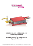
JIVE Regler
Bedienungsanleitung
JIVE Speed Controls
Operation Manual
1
Inhaltsverzeichnis
1
EINLEITUNG .................................................................................................................................................................... 4
2
TECHNISCHE DATEN ..................................................................................................................................................... 4
3
EIGENSCHAFTEN DER JIVE REGLER ......................................................................................................................... 4
3.1
3.2
3.3
3.4
3.5
3.5.1
3.5.2
3.5.3
4
4.1
4.2
4.3
4.4
4.5
4.6
4.7
4.8
4.9
HIGHLIGHTS: ................................................................................................................................................................... 4
BEC ............................................................................................................................................................................... 5
RINGKERN ....................................................................................................................................................................... 5
TIEFENTLADUNGSSCHUTZ ................................................................................................................................................ 5
ANSCHLUSS DER KABEL .................................................................................................................................................. 5
BEC-KABEL: ................................................................................................................................................................ 6
MOTOR-KABEL ............................................................................................................................................................. 6
AKKU KABEL ................................................................................................................................................................. 6
ANPASSUNG DES REGLERS AN DIE FERNSTEUERUNG ......................................................................................... 7
DER AUTO-PROGRAMMIER-MODUS APM (MODUS 1) ........................................................................................................ 8
DER SEGELFLUG-MODUS (MODUS 2) ............................................................................................................................... 9
DER MOTORFLUG- / BOOT-MODUS (MODUS 3) ............................................................................................................... 10
DER HELI-MODUS (MODUS 4) ........................................................................................................................................ 11
DER WETTBEWERBS-MODUS (F5B / F5D) (MODUS 5) .................................................................................................... 12
MODUS 6 ....................................................................................................................................................................... 13
DREHRICHTUNGSUMKEHR (MODUS7).............................................................................................................................. 14
MODUS 8 MOTORFLUGMODUS MIT EINSTELLBARER “F3A-BREMSE” ............................................................................... 14
LIPO-MODUS (MODUS 9)................................................................................................................................................ 15
5
SICHERHEITSHINWEISE .............................................................................................................................................. 16
6
FEHLERSUCHE ............................................................................................................................................................. 16
6.1 FEHLER BEIM ANSTECKEN DES AKKUS ........................................................................................................................... 16
6.2 FEHLER WÄHREND DER PROGRAMMIERUNG .................................................................................................................... 16
6.3 FEHLER IM BETRIEB ....................................................................................................................................................... 17
6.3.1 UNERWARTETE MOTORABSCHALTUNG – W ENN SIE NACH DER ABSCHALTUNG KEIN GAS MEHR GEBEN, ZEIGT DIE LED
NACH DER LANDUNG DEN ABSCHALTGRUND AN. ........................................................................................................................ 17
6.3.2 MOTOR LÄSST SICH NICHT EINSCHALTEN: ..................................................................................................................... 17
7
7.1
7.2
7.3
7.4
7.5
7.6
8
ALLGEMEINES .............................................................................................................................................................. 18
KÜHLUNG / BEFESTIGUNG .............................................................................................................................................. 18
TEILLASTFESTIGKEIT...................................................................................................................................................... 18
AKTIVER FREILAUF ........................................................................................................................................................ 18
SENSORLOSE KOMMUTIERUNG: ..................................................................................................................................... 18
VARIABLE TAKTFREQUENZ ............................................................................................................................................. 18
BERATUNG / TECHNISCHE HILFE / HOTLINE .................................................................................................................... 18
GEWÄHRLEISTUNG ..................................................................................................................................................... 19
2
1
INTRODUCTION ............................................................................................................................................................ 21
2
TECHNICAL DATA OF THE JIVE SPEED CONTROLS .............................................................................................. 21
3
FEATURES OF THE JIVE SPEED CONTROLS........................................................................................................... 21
3.1
3.2
3.3
3.4
3.4.1
3.4.2
3.4.3
4
4.1
4.2
4.3
4.4
4.5
4.6
4.7
4.8
4.9
BEC ............................................................................................................................................................................. 22
TOROIDAL CORE ............................................................................................................................................................ 22
LOW VOLTAGE CUT-OFF ................................................................................................................................................. 22
CONNECTION OF THE CABLES ......................................................................................................................................... 22
MOTOR CABLES .......................................................................................................................................................... 22
BATTERY CONNCTOR .................................................................................................................................................. 22
CONNECTION TO THE RECEIVER ................................................................................................................................... 23
SETTING UP THE SPEED CONTROL TO YOUR EQUIPMENT.................................................................................. 23
AUTO-PROGRAMMING-MODE APM - RESET (MODE 1) .................................................................................................... 24
GLIDER-MODE (MODE 2)................................................................................................................................................ 25
MOTOR-PLANE-/ BOAT-MODE (MODE 3) ........................................................................................................................ 26
HELI-MODE (MODE 4) .................................................................................................................................................... 27
COMPETITION-MODE / FAI MODE (MODE 5) .................................................................................................................... 28
CAR-MODE RACE: ONE DIRECTION, PROPORTIONAL BRAKE (MODE 6) ............................................................................. 29
REVERSE MOTOR ROTATION (MODE 7)........................................................................................................................... 30
F3A MOTORPLANE MODE (MODE 8)............................................................................................................................... 30
LIPO MODE (MODE 9) .................................................................................................................................................... 31
5
NOTES ON SAFETY ...................................................................................................................................................... 32
6
TROUBLE SHOOTING .................................................................................................................................................. 32
6.1 ERROR WHILE CONNECTION THE BATTERY ...................................................................................................................... 32
6.2 ERRORS WHILE PROGRAMMING ...................................................................................................................................... 32
6.3 ERRORS IN USE.............................................................................................................................................................. 33
6.3.1 UNEXPECTED MOTOR CUT OFF: THE LED SHOWS THE REASON, IF NOT TURNED ON THE THROTTLE AGAIN AFTER CUT OFF 33
6.3.2 MOTOR CAN NOT BE STARTED:..................................................................................................................................... 33
7
7.1
7.2
7.3
7.4
7.5
7.6
8
GENERAL INFORMATION ............................................................................................................................................ 34
COOLING / FIXING .......................................................................................................................................................... 34
PART LOAD CAPABILITY ................................................................................................................................................ 34
THE ACTIVE FREE WHEELING CIRCUIT .............................................................................................................................. 34
SENSORLESS COMMUTATION ......................................................................................................................................... 34
VARIABLE PWM SWITCHING FREQUENCY ....................................................................................................................... 34
TECHNICAL SUPPORT / HOTLINE/KONTRONIK SERVICE................................................................................................ 34
WARRANTY ................................................................................................................................................................... 35
3
Allgemeines
1
Einleitung
Mit dem JIVE Regler haben Sie ein hochwertiges Elektronikprodukt aus deutscher Entwicklung und Fertigung erworben.
Bitte lesen Sie diese Bedienungsanleitung gründlich durch, um sich mit dem Regler vertraut zu machen und
Fehlbedienungen zu vermeiden.
Die JIVE Regler sind voll teillastfeste sensorlose Regler für bürstenlose Motoren. Sie regeln sehr feinfühlig und verfügen
über einen weichen, ruckfreien und dennoch sehr schnellen Anlauf. Die vordefinierten Betriebs-Modi ermöglichen eine
schnelle Anpassung des JIVE an verschiedene Anwendungen im Flugzeug, Hubschrauber oder Boot. Ein Highlight der
JIVE Regler ist die dynamische, automatische Einstellung der Taktfrequenz und des Kommutierungswinkels. Damit ist
gewährleistet, dass der angeschlossene Motor im aktuellen Lastfall mit dem bestmöglichen Wirkungsgrad betrieben wird.
Speziell im Teillastbetrieb ermöglicht dies längere Flugzeiten bzw. mehr Motorleistung. Dadurch bleibt auch der Motor
kühler. Dies stellt einen großen Vorteil gegenüber der sonst üblichen festen Timingeinstellung dar. Eine weitere Neuheit
ist die Dauerbelastbarkeit. Die spezifizierten Werte können bei entsprechender Kühlung noch deutlich gesteigert
werden.
2
Technische Daten
Typ
Eingangsspannung
Dauerstrom1
JIVE 80+ LV
JIVE 100+ LV
JIVE 60+ HV
JIVE 80+ HV
6V-25V
6V-25V
16-50V
16-50V
80A
100A
60A
80A
3
BEC Spannung
(standard / min max)
5,6V / 5V–6V
5,6V / 5V–6V
5,6V / 5V–6V
5,6V / 5V–6V
BEC Strom
(Dauer/max)
5A / 15A
5A / 15A
5A / 15A
5A / 15A
Eigenschaften der JIVE Regler
Die JIVE Regler verfügen über eine Modusprogrammierung. Jeder Modus stellt die für den jeweiligen Betriebszustand
benötigten Parameter selbst ein. Eine aufwendige Programmierung der einzelnen Parameter wie z.B. dynamisches-,
drehmoment- oder drehzahloptimiertes Timing, Unterspannungsabschaltung, EMK-Bremse etc. entfällt. Sollen diese
Eigenschaften einzeln verändert werden, so ist dies über ProgCARD (Best.-Nr.: 9305) möglich. Zusätzlich sind über die
ProgCARD II (Best.-Nr.: 9306) weitere Parameter einstellbar (siehe Kapitel 4).
3.1
Highlights:
• Sensorloser Betrieb, es werden keine Sensorsignale vom Motor benötigt
• Modusprogrammierung
o Auto-Programmier-Modus (APM) (Standard - keine Programmierung nötig)
o Segelflug- oder Motorflug- / Boot-Modus
o Heli-Modus, echte Drehzahlregelung möglich
o Wettbewerbsmodus
o Car-Modus : Race: Vorwärts, Prop. Bremse
o Drehrichtungsumkehr
o Lipo-Modus
• EMK-Bremse abschaltbar, Bremsgeschwindigkeit einstellbar
• F3A Bremse, einstellbar in 10% Schritten per Sender bzw. 2,5% Schritten per ProgCARD II
• Automatische Unterspannungsabschaltung, abschaltbar und in der Spannung veränderbar. Abregelung statt
Abschaltung ist möglich.
• Unbegrenzt teillastfest (aktiver Freilauf)
• Selbsttest und Abschaltanalyse (Abschaltgrund wird angezeigt)
• Einstellkontrolle per LED oder akustischem Signal
• Sehr feinfühliges Regelverhalten, kein Ruckeln beim Anlaufen
• Automatische Erfassung der Motorparameter dadurch
1
Bezogen auf 2,4Ah Akkukapazität und 1m/s Kühlluft mit 22°C, kann durch verbesserte Kühlung erheblich gesteigert
werden
4
Allgemeines
o
o
Automatisch angepasste Taktfrequenz (8-32kHz)
Dynamisches Timing
• Anlauf-, Blockier-, Übertemperaturschutz, Strombegrenzung
• 100% SMD-Technik, sehr klein und leicht, hochflexible, „lötkolbenfeste“ Kabel
• Digitale Mikroprozessorsteuerung, kein Temperaturdrift, „Update-fähig"
• 24 Monate Gewährleistung, CE geprüft, schneller Reparaturservice, kostenlose Hotline
• Entwickelt und produziert in Rottenburg, Deutschland
3.2
BEC
Alle JIVE Regler verfügen über ein leistungsstarkes getaktetes BEC. Im Gegensatz zu herkömmlichen BEC-Systemen ist
die Belastbarkeit dieses BECs weitgehend unabhängig von der Eingangsspannung. Damit ist die Verwendung des BECs
auch bei höheren Spannungen möglich. Zudem zeichnet sich das BEC durch eine bislang ungekannte Störfestigkeit aus.
Bei den JIVE Reglern ist es möglich die BEC Spannung in 0,2V Schritten von 5V bis 6V einzustellen. Aus
Sicherheitsgründen muss parallel zum BEC ein 4-Zelliger NiMH Akku am Empfänger eingesteckt werden. Bei einer
eingestellten BEC-Spannung von mehr als 5,6V sollte eine redundante Empfängerstromversorgung mit
Wechselschaltung verwendet werden.
Ein Betrieb ohne BEC ist ebenfalls möglich. Das rote Empfängerkabel wird dazu jeweils aus dem Stecker gezogen oder
durchtrennt.
Haben Sie Fragen oder sind Sie sich unsicher? Gerne können Sie unsere aus Deutschland kostenlose Hotline in
Anspruch nehmen (Tel.: 0800 / BRUSHLESS)
3.3
Ringkern
Der Ringkern in den Empfängeranschlusskabeln dient der Störunterdrückung und ist für die Betriebssicherheit des
Reglers notwendig und darf nicht entfernt werden. Er kann bei Bedarf aber innerhalb des Kabels verschoben werden.
3.4
Tiefentladungsschutz
Die JIVE Regler sind je nach Modus mit einem automatischen Tiefentladungsschutz ausgestattet. Dieser schaltet den
Motor ab, wenn die Akkuentladespannung erreicht ist (NiMH: ca.0.8V/Zelle). Der Motor kann jedoch per Fernsteuerung
wieder eingeschaltet werden, indem der Gasknüppel zuerst in die Motor-Aus-Stellung und anschließend wieder in die
gewünschte Gas-Stellung gebracht wird. Bitte beachten Sie die veränderte Abschaltspannung (2,7V/Zelle) im Lipo–
Modus! Die Abschaltspannungen können mit der ProgCARD verändert werden.
3.5
Anschluss der Kabel
Programmierstecker
Empfänger
(beliebiger
Steckplatz)
Empfänger
(Kanal mit
Gasfunktion)
5
Allgemeines
3.5.1 BEC-Kabel:
Mit 5A Dauerstrom und 15A Maximalstrom ermöglicht der JIVE die Verwendung des BEC auch zur Versorgung
leistungsstarker Digitalservos. Um den Übergangswiderstand zu minimieren verfügen alle JIVE Regler über zwei BEC
Anschlussbuchsen. Um das BEC voll belasten zu können müssen immer beide Buchsen über ServoKabel mit
integriertem Ringkern verwendet werden. Die mit „Master“ gekennzeichnete Buchse muss dabei an dem
Empfängerkanal angeschlossen werden der die Gasfunktion übernimmt. Die „Slave“-Buchse kann mit jedem beliebigen
freien Empfängerkanal (auch einem Batterieanschluss) verbunden werden. Ein zusätzliches Kabel kann unter #9250
erworben werden.
WARNUNG: Achten Sie unbedingt auf die korrekte Polung der Steckverbindungen am Empfänger! Viele Empfänger mit
„UNI“-Stecksystem haben keine verpolsicheren Buchsen. Eine falsche Polung der BEC Kabel am Empfänger kann zu
Schäden am Empfänger und den angeschlossenen Servos führen!
3.5.2 Motor-Kabel
Die Reihenfolge ist beliebig. Das Tauschen von 2 Motorkabeln ändert die Motordrehrichtung (siehe auch Modusprogrammierung Modus 7).
Sollte der Motor über Sensorleitungen verfügen, so werden diese nicht benötigt und bleiben unbenutzt.
3.5.3 Akku Kabel
An den Akkukabeln sollten verpolungssichere Stecker verwendet werden, da eine Verpolung irreparable Schäden
hervorruft. Eine Verpolung wird im Fehlerspeicher hinterlegt und kann vom Service ausgelesen werden.
6
Programmierung
4
Anpassung des Reglers an die Fernsteuerung
Der JIVE Regler kann sowohl mit dem Fernsteuersender als auch mit den Programmierkarten eingestellt werden. Für
die Programmierung per Sender sind Einstellungen für verschiedene Anwendungen vorgegeben
(Modusprogrammierung). Zusätzlich können mit der ProgCARD und der ProgCARD II die Einstellungen der Modi
verändert werden:
ProgCARD:
ProgCARD II
•
Knüppelwege
Knüppelwegs
fest/APM,
einlernen
des
•
„F3A-Bremse“ 10% bis
Schritten
100% in 2,5%
•
Unterspannungsabschaltung
o NiMH: 0,7V/0,8V/0,9V/1,0V pro Zelle
o Lipo: 2,5V/2,7V/2,8V/3,0V pro Zelle
•
BEC-Spannung (5,0V bis 6,0V in 0,2V
Schritten)
•
Drehrichtungsumkehr
•
Bremse Ein/Aus
•
•
Drehzahlregelung Ein/Aus
Feineinstellung der Regelparameter für die
Drehzahlregelung
•
Hochlaufzeit bei Drehzahlregelung 6/8/10/12
Sekunden
•
Verkürzung
der
„Hold“-Funktion
ungültigem Empfangssignal
•
Motortiming: Auto/-5°/+5°/+10°/+15°
•
Ansprechverhalten: weich/schnell
bei
Der Regler befindet sich im Neuzustand im APM (Auto-Programmier-Modus), d.h. er gleicht sich selbst auf die
Knüppelwege der Fernsteuerung ab:
a)
b)
c)
d)
Sender einschalten - Gasknüppel auf Anschlag EMK-Bremse stellen.
Empfänger einschalten.
Antriebsakku an JIVE Regler anschließen.
Vor dem Start oder beim Start für mind. 1sec. Vollgas geben.
e) Fertig.
Sollte der Motor nicht anlaufen: Antriebsakku abziehen und im Sender die Funktion „Drehrichtungsumkehr“ einbzw. ausschalten. Weiter ab a).
In allen andern Modi der Modusprogrammierung werden die Knüppelwege fest programmiert und müssen nicht
bei jedem Start neu eingelernt werden.
7
Programmierung
4.1
Der Auto-Programmier-Modus APM (Modus 1)
Im APM „lernt“ der Regler nach jedem Anstecken des Akkus die Knüppelwege selbständig neu ein. Die
Bremsgeschwindigkeit steht auf Mitte (ca. 0,5 sec.), die Unterspannungsabschaltung ist auf 0,8 V/Zelle (NiMH)
eingestellt.
Das Programmieren des APM löscht alle bisherigen Einstellungen und versetzt den JIVE Regler in den
Auslieferungszustand. (Reset)
Programmierablauf des Auto-Programmier-Modus
Jumper (schwarzer Stecker) auf die 2 gekennzeichneten Programmierkontakte aufstecken.
Für ein akustisches Signal, den Motor am Regler anschließen.
Sender und Empfänger einschalten. Gasknüppel in
Bremsstellung bringen (Knüppel hinten).
Antriebsakku anstecken.
2 sec. warten, oder bis
aufsteigende Tonfolge
Jumper abziehen.
absteigende Tonfolge
Gas-Knüppel in Vollgasstellung bringen (Knüppel vorn).
absteigende Tonfolge
Kontrollausgabe
Fertig - Antriebsakku abziehen.
8
Programmierung
4.2
Der Segelflug-Modus (Modus 2)
Alle für den Betrieb eines Seglers benötigten Eigenschaften werden selbständig eingestellt.
• Die Bremsgeschwindigkeit ist auf Mitte (ca. 0,5 sec.) eingestellt, und damit auch für den Einsatz von
Getriebeantrieben geeignet.
• Die Unterspannungsabschaltung von 0,8 V/Zelle (NiMH) schließt eine Tiefenentladung des Akkus aus.
• Der Übertemperaturschutz und die Strombegrenzung des Reglers sind aktiviert, um bei Überlastung den Motor
abzuschalten.
• Die Gaskennlinie ist für den Betrieb mit Luftschrauben optimiert.
• Die Anlaufgeschwindigkeit ist auf große, langsam laufende Luftschrauben optimiert.
• Außer der Brems- und der Vollgas-Position kann eine separate Motor-Aus-Position des Gasknüppels programmiert
werden. In dieser Knüppelstellung ist der Motor ausgeschaltet, die Bremse aber noch nicht aktiv. Beim Klapppropeller
bleibt dieser gezielt offen um das Modell zu bremsen. Dies wird als Thermikbremse genutzt.
• Wird keine separate Motor-Aus-Stellung programmiert, so ist die Motor-Aus-Stellung mit der Bremsstellung identisch.
Programmierablauf des Segelflugmodus-Modus (Modus 2)
Jumper (schwarzer Stecker) auf die 2 gekennzeichneten Programmierkontakte aufstecken.
Für ein akustisches Signal, den Motor am Regler anschließen.
Sender und Empfänger einschalten. Gas-Knüppel in Bremsstellung bringen
(Knüppel hinten).
Antriebsakku anstecken.
2 sec. warten, oder bis
aufsteigende Tonfolge
Jumper abziehen.
absteigende Tonfolge
...
Gas-Knüppel in Vollgasstellung bringen (Knüppel vorn).
absteigende Tonfolge
Jetzt kann der Gas-Knüppel in eine separate MotorAus-Stellung gebracht werden (optional).
absteigende Tonfolge
Kontrollausgabe
Fertig - Antriebsakku abziehen.
9
Programmierung
4.3
Der Motorflug- / Boot-Modus (Modus 3)
Alle für den Betrieb eines Motormodells oder Rennbootes benötigten Eigenschaften werden selbstständig eingestellt.
• Im Motorflug- / Boot-Modus ist die EMK-Bremse des Reglers ausgeschaltet.
• Die Unterspannungsabschaltung von 0,8 V/Zelle ist deaktiviert, da im Motormodell oder Boot ein Absinken der
Versorgungsspannung deutlich zu spüren ist, und so die Flugfähigkeit bzw. die Manövrierfähigkeit des Modells bis zu
Schluss erhalten bleibt.
• Der Übertemperaturschutz und die Strombegrenzung des Reglers sind aktiviert, um bei Überlastung den Motor
abzuschalten.
• Die Gaskennlinie ist für den Betrieb mit Luftschrauben und Schiffspropeller optimiert.
Programmierablauf des Motorflug- / Boot-Modus (Modus 3)
Jumper (schwarzer Stecker) auf die 2 gekennzeichneten Programmierkontakte aufstecken.
Für ein akustisches Signal, den Motor am Regler anschließen.
Sender und Empfänger einschalten.
Gas-Knüppel in Motor-Aus-Stellung bringen (Knüppel hinten).
Antriebsakku anstecken.
2 sec. warten, oder bis
aufsteigende Tonfolge
Jumper abziehen.
absteigende Tonfolge
...
...
Gas-Knüppel in Vollgasstellung bringen (Knüppel vorn).
absteigende Tonfolge
Kontrollausgabe
Fertig - Antriebsakku abziehen.
10
Programmierung
4.4
Der Heli-Modus (Modus 4)
Der Heli-Modus des JIVE Reglers aktiviert die Drehzahlregelung. Das bedeutet, dass die Motordrehzahl konstant
gehalten wird. Lastschwankungen und das Absinken der Akkuspannung werden kompensiert, solange die Leistung des
Akkus und des Motors dafür ausreichen. Es wird kein separater Mixer der Fernsteuerung benötigt, um die Rotordrehzahl
zu stabilisieren. Diese Drehzahlregelung funktioniert nur im eingebauten Zustand. Wird der Motor ohne die
Schwungmasse des Helikopters betrieben, kann ein ruckender Betrieb entstehen.
Das Fernsteuerkabel des Reglers wird in einen freien Empfängeranschluss gesteckt, der vom Sender aus mittels
Schieberegler (ohne Mischer) bedient wird. Dieser Schieber wird dann auch zum Programmieren des Heli-Modus
verwendet.
Die Drehzahlregelung des JIVE lernt sich beim ersten Start des Motors nach dem Anstecken des Akkus selbständig auf
die Anwendung ein. Am besten immer auf 0° Pitch stellen, damit die Drehzahl bei jedem Flug annähernd gleich ist.
Zum Starten, den Schieber Richtung Vollgas schieben. Mittels Sanftanlauf erhöht der Regler innerhalb einiger Sekunden
die Motordrehzahl. Wenn die für die Drehzahlregelung nötige Drehzahl erreicht ist, schaltet er auf Regelung um. Je näher der Schieber der Vollgasstellung kommt, desto höher ist die eingeregelte Drehzahl.
Erreicht der Schieber die Motor-Aus Stellung, so wird der Motor ausgeschaltet. Dies sollte während des Fluges
vermieden werden, da ansonsten zum Wiederanfahren durch den Sanftanlauf einige „lange“ Sekunden benötigt werden.
Um festzustellen, ob Motor, Getriebeübersetzung, Akku und Hubschrauber richtig auf einander abgestimmt sind, gibt es
eine Kontrollmöglichkeit: Nachdem der JIVE Regler abgeglichen ist, sollte die niedrigste einstellbare Drehzahl nicht zum
Abheben des Hubschraubers ausreichen. Ist dies dennoch der Fall, so wird der JIVE Regler jenseits seiner
Maximalwerte betrieben und ist vermutlich überlastet. Dann muss eine höhere Getriebeübersetzung oder ein Motor mit
geringerer Drehzahl und mehr Drehmoment eingesetzt werden!
Im Heli-Modus sind folgende Schutzmechanismen aktiviert:
• Wenn mehr als drei Sekunden kein Empfangssignal erkannt wird, schaltet der Regler den Motor ab.
• Bei Übertemperatur regelt er langsam (ca. 30sec.) das Gas auf Null ab.
• Wenn der Lipo-Modus aktiviert ist führt die Erkennung der Unterspannungsabschaltung ebenfalls zur langsamen
Abregelung, ohne Lipo-Modus ist die Unterspannungsabschaltung deaktiviert. Im Lipo Modus sollte nicht bis zur
Unterspannungsabschaltung geflogen werden, da diese aus Sicherheitsgründen später greift als in den anderen
Modi.
Ein erneuter Start ist erst nach Trennen und Wiederanstecken des Akkus möglich.
Programmierablauf des Heli-Modus (Modus 4)
Jumper (schwarzer Stecker) auf die 2 gekennzeichneten Programmierkontakte aufstecken.
Für ein akustisches Signal, den Motor am Regler anschließen.
Sender und Empfänger einschalten. Schieberegler in Motor-Aus-Stellung bringen (Stellung hinten).
Antriebsakku anstecken.
2 sec. warten, oder bis
aufsteigende Tonfolge
Jumper abziehen.
absteigende Tonfolge
...
...
...
Schieberegler in Vollgasstellung bringen (Stellung vorn).
absteigende Tonfolge
Kontrollausgabe
Fertig - Antriebsakku abziehen.
11
Programmierung
4.5
Der Wettbewerbs-Modus (F5B / F5D) (Modus 5)
Alle für den Betrieb eines Wettbewerbsmodells benötigten Eigenschaften werden selbständig eingestellt.
• Die Anlaufgeschwindigkeit ist für schnellen Anlauf mit großen Luftschrauben optimiert.
• Die EMK-Bremsleistung des Reglers steht auf maximaler Ansprechgeschwindigkeit, um ein sofortiges Anklappen der
Luftschraube zu erreichen.
Achtung: Dies führt zu großen Kräften, denen alle Komponenten gewachsen sein müssen.
• Die Unterspannungsabschaltung und die Übertemperaturabschaltung ist deaktiviert, da im Wettbewerb störend.
Achtung: Für ausreichend Kühlung sorgen.
• Die Strombegrenzung ist maximiert.
• Zum Schutz des Reglers ist die Zeit, in der Teillast zugelassen wird, begrenzt. Wird sie überschritten schaltet der
Regler ab.
• Zum Start sind 6sec Teillast erlaubt. Sind die ersten Einschaltzeiten in Summe kürzer als 2sec (z.B. zum Test) so
zählt das nicht. Alle weiteren Einschaltungen lassen 1sec Teillast zu, danach schaltet der JIVE ab.
Programmierablauf des Wettbewerbs-Modus (Modus 5)
Jumper (schwarzer Stecker) auf die 2 gekennzeichneten Programmierkontakte aufstecken.
Für ein akustisches Signal, den Motor am Regler anschließen.
Sender und Empfänger einschalten. Motorschalter in
Bremsstellung bringen (Schalter hinten).
Antriebsakku anstecken.
2 sec. warten, oder bis
aufsteigende Tonfolge
Jumper abziehen.
absteigende Tonfolge
...
...
...
Motorschalter in Vollgasstellung bringen (Schalter vorn).
absteigende Tonfolge
Kontrollausgabe
Fertig - Antriebsakku abziehen.
12
Programmierung
4.6
Modus 6 (Car-Modus)
Alle für den Betrieb eines Modellautos benötigten Eigenschaften werden selbständig eingestellt.
• Die EMK-Bremse des Reglers arbeitet proportional, d.h. bei der Programmierung ist ein ausreichender Knüppelweg
für die Bremse notwendig.
• Die Anlaufparameter sind für das Anfahren im Auto optimiert.
• Die Unterspannungsabschaltung von 0,8 V/Zelle (NiMH) ist deaktiviert, der Lipo Modus ist zusätzlich programmierbar
• Der Übertemperaturschutz und die Strombegrenzung des Reglers sind aktiviert, um bei Überlastungen den Motor
abzuschalten.
• Die Ansprechgeschwindigkeit ist maximiert, um ein direktes Fahrgefühl zu vermitteln.
• Die Gaskennlinie ist auf den Fahrbetrieb abgestimmt.
Programmierablauf des Car-Modus Race (Modus 6)
Jumper (schwarzer Stecker) auf die 2 gekennzeichneten Programmierkontakte aufstecken.
Für ein akustisches Signal, den Motor am Regler anschließen.
Sender und Empfänger einschalten. Gas-Knüppel in
Motor-Aus-Stellung bringen (Knüppel in der Mitte).
Antriebsakku anstecken.
2 sec. warten, oder bis
aufsteigende Tonfolge
Jumper abziehen.
absteigende Tonfolge
...
...
...
Gas-Knüppel in Vollgasstellung bringen (Knüppel vorn).
absteigende Tonfolge
Gas-Knüppel in Bremsstellung bringen (Knüppel hinten).
absteigende Tonfolge
Kontrollausgabe
Fertig - Antriebsakku abziehen.
13
Programmierung
4.7
Drehrichtungsumkehr (Modus7)
Um die Drehrichtung des Motors umzukehren, entweder zwei Motorkabel tauschen oder den Modus 7 programmieren.
Er verändert vorher programmierte Eigenschaften nicht. Dazu bei der Programmierung auf das 7-fach Signal warten,
ansonsten wie bei Modus 3.
Modus 7 lässt sich nur programmieren, wenn zuvor irgendein Modus außer Modus 1 programmiert wurde.
4.8
Modus 8 Motorflugmodus mit einstellbarer “F3A-Bremse”
Dieser Modus entspricht im Wesentlichen Modus 3 (Motorflugmodus), zusätzlich kann in diesem Modus eine fest
einstellbare Motorbremse programmiert werden („F3A-Bremse“). Diese dient dazu Flugmodelle in Abwärtspassagen zu
bremsen. Mit der ProgCARD II kann die Bremsstärke in 2,5% Schritten eingestellt werden.
Programmierablauf
Jumper (schwarzer Stecker) auf die 2 gekennzeichneten Programmierkontakte aufstecken.
Für ein akustisches Signal, den Motor am Regler anschließen.
Sender und Empfänger einschalten. Gas-Knüppel in
Motor-Aus-Stellung bringen (Knüppel in der Mitte).
Antriebsakku anstecken.
2 sec. warten, oder bis
aufsteigende Tonfolge
Jumper abziehen.
absteigende Tonfolge
...
...
Gas-Knüppel in Vollgasstellung bringen (Knüppel vorn halten).
Signaltöne für die Stärke der F3A Bremse, jeder Ton entspricht 10% Bremsstärke
Bei gewünschter Bremsstärke Gas-Knüppel in Motor-Aus Stellung bringen.
absteigende Tonfolge
Kontrollausgabe
Fertig - Antriebsakku abziehen.
14
Programmierung
4.9
Lipo-Modus (Modus 9)
Diesen Modus zusätzlich programmieren um auf die automatische Unterspannungsabschaltung für Lipo-Akkus (Abschaltspannung 2,7V bis 3V/Zelle) je nach Last umzustellen.
Er verändert vorher programmierte Eigenschaften nicht. Dazu bei der Programmierung auf das 9-fach Signal warten,
ansonsten wie bei Modus 3.
Zur Erkennung der veränderten Unterspannungsabschaltung ist die Tonfolge beim Anstecken des Flugakkus geändert.
Die Anzahl der Pieptöne entspricht der Anzahl der erkannten Lipo-Akkus.
ACHTUNG: Das Programmieren dieses Modus aktiviert die Unterspannungsabschaltung auch in den Modi, in
denen ansonsten die Unterspannungsabschaltung deaktiviert ist.
NEU: Bei aktiviertem Lipomodus wird beim anstecken des Akkus die erkannte Zellenzahl akustisch
ausgegeben. Ist die erkannte Zellenzahl geringer als die reale sollte nicht geflogen werden, da sonst die
Abschaltung zu spät greifen würde. In diesem Fall sollte der Akku vor dem Flug nachgeladen werden.
15
Service und Gewährleistung
5
Sicherheitshinweise
• Nicht den Akku vom JIVE Regler abziehen, solange der Motor noch läuft.
• Nicht den Regler selbst mit Kabelbindern o.ä. befestigen. Es könnten Bauteile beschädigt werden.
• Sobald Antriebsakku und Motor an den Regler angeschlossen sind, besteht die Möglichkeit, dass der Motor anläuft
(z.B. durch Fehlbedienung oder durch elektrischen Defekt). Höchste Vorsicht ist ab diesem Zeitpunkt geboten.
• Ein Elektromotor (speziell mit Luftschraube) kann erhebliche Verletzungen verursachen. Ebenso können durch
umherfliegende Teile erhebliche Verletzungen hervorgerufen werden.
• Der Betrieb dieses Reglers ist nur in Situationen zulässig, in denen Sach- und Personenschäden ausgeschlossen
sind.
• Einen beschädigten Regler (z.B. durch mechanische oder elektrische Einwirkung, durch Feuchtigkeit, usw.) keinesfalls
weiter verwenden. Anderenfalls kann es zu einem späteren Zeitpunkt zu einem plötzlichen Versagen des Reglers
kommen.
• Der Regler ist nur zum Einsatz in Umgebungen vorgesehen, in denen keine Entladung von statischer Elektrizität
auftritt.
• Der Regler darf nur aus NiCd-, NiMH-, Lipo- oder Blei-Akkumulatoren gespeist werden. Ein Betrieb an Netzgeräten ist
nicht zulässig. Es darf in keinem Falle eine elektrische Verbindung zwischen dem Regler und dem 230V Wechselstromnetz hergestellt werden. Bei Akkumulatoren mit hoher Kapazität muss gewährleistet sein, dass der Regler
ausreichend gekühlt wird.
• Eine Verlängerung der Akku- oder Motorkabel sind nicht zulässig, da ansonsten die Einhaltung gesetzlicher
Vorschriften nicht gewährleistet ist. Zu lange Akkukabel können zur Beschädigung des Reglers führen.
• Bei Strommessungen ist unbedingt ein Zangenampermeter zu verwenden, da ein eingeschleiftes Messgerät / -shunt
den Regler beschädigen kann.
• Vor dem Erstflug müssen Tests am Boden durchgeführt werden, um sicherzustellen, dass die BEC-Belastbarkeit für
die jeweilige Anwendung ausreicht.
• Grundsätzlich ist immer für genug Kühlung zu sorgen, um ein Überhitzen des Reglers zu verhindern.
6
Fehlersuche
6.1
Fehler beim Anstecken des Akkus
Der JIVE Regler verfügt über einen zweiten Microprozessor, bereits beim Anstecken des Akkus wird ein umfangreicher
Selbstest durchgeführt, wenn der Regler nach dem Selbsttest nicht funktioniert und einen Fehlercode ausgibt wenden Sie
sich bitte an die Hotline oder schicken Sie eine Email an [email protected].
6.2
Fehler während der Programmierung
• Es kommt kein Signal:
o
o
o
Der Sender ist nicht eingeschaltet.
Der Regler ist nicht oder falsch im Empfänger eingesteckt
Es ist kein Empfängerakku angeschlossen.
• Signal - dann Dauerlicht oder kein weiteres Signal:
o
o
Die Knüppelstellung „hinten“ (Brems- bzw. Motor-Aus-Stellung) ist zu dicht an der Knüppelstellung „vorne“
(Vollgasstellung).
Der Abstand zwischen der Knüppelstellung „hinten“ (Brems- bzw. Motor-Aus-Stellung ) und Knüppelstellung
„vorne“ (Vollgasstellung) ist zu groß. Dieser Fehler kann nur bei Computersendern auftreten.
Abhilfe: Den Servoweg für den Gas-Knüppel auf +/-100% (ggf. auch weniger) programmieren.
o
Starke Verschiebung der Knüppelstellungen in Richtung lange Impulse (eine der Knüppelstellungen muss eine
Impulslänge kürzer als 2ms besitzen). Dieser Fehler kann nur bei Computersendern auftreten.
Abhilfe: Am Fernsteuersender keine Verschiebung (Offset) der Servowege programmieren.
16
Service und Gewährleistung
6.3
Fehler im Betrieb
6.3.1
Unerwartete Motorabschaltung – Wenn Sie nach der Abschaltung kein Gas mehr geben, zeigt die LED
nach der Landung den Abschaltgrund an.
Blinkcode:
Einfach
Zweifach
Bedeutung
Unterspannung
Überstromabregelung (Softwareerkennung)
Dreifach
Vierfach
Übertemperatur
Mehr als 4s keine Empfängerimpulse
Fünffach
Zu lange Teillast in Modus 5
Sechsfach
Hardware Reset im Betrieb wegen Unterspannung der
internen Stromversorgung
Unerwarteter Reset im Betrieb
Hard ware Überstromerkennung, sofortiges Abschalten,
kein Abregeln möglich, kein Wiedereinschalten möglich
Siebenfach
Achtfach
Abhilfe
Kleinerer Propeller oder Antriebsakku mit
weniger Zellen verwenden
Für bessere Kühlung sorgen
Reichweitentest durchführen und
Empfangsanlage optimieren
Teillast vermeiden, ggf. Programmierung
kontrollieren (Temperaturdrift des Senders)
BEC Überlast?
Extreme Überlast, möglicherweise durch
mechanisch blockierten Motor, ggf. Mechanik
kontrollieren
Kann der Abschaltgrund nicht zuverlässig verhindert werden, sollte in jedem Fall der KONTRONIK Service
kontaktiert werden, um eine Zerstörung des Reglers zu vermeiden.
Tel.: 0800 / Brushless (aus Deutschland kostenlos)
6.3.2 Motor lässt sich nicht einschalten:
Der Regler gibt nach Anschluss des Antriebsakkus den Motor erst frei nach Erkennung der Knüppelstellung „hinten“
(Brems- bzw. Motor-Aus-Stellung ) oder „Neutral“ (Motor-Aus-Stellung). Erkennt der Regler keine dieser Stellungen,
erfolgt kein aufsteigender Dreifachton
und der Motor bleibt ausgeschaltet.
Abhilfe:
•
Position der Trimmung des Gas-Knüppel beachten und auf Motor-Aus bzw. Bremse stellen.
•
Den Regler auf die aktuellen Servowege programmieren.
•
Manche Fernsteueranlagen weisen eine gewisse Temperaturdrift der Servowege auf. In diesem Fall empfiehlt es
sich, bei der Programmierung etwas Abstand von den Anschlagstellungen des Gasknüppels einzuhalten, um im
Betrieb etwas Reserveweg zur Verfügung zu haben.
.
17
Service und Gewährleistung
7
Allgemeines
Mit diesem JIVE Regler haben Sie ein hochwertiges Produkt erworben. Hochwertige Steckkontakte (z.B. KONTRONIK
Stecker Best.Nr.: 9010) sowie niederohmig verlötete Akkus sollten daher obligatorisch sein. Sollten Sie noch Fragen bzgl.
des Einsatzes dieses Reglers haben (z.B. tats. auftretende Motorströme) bitte den KONTRONIK Service kontaktieren.
7.1
Kühlung / Befestigung
Ausreichende Kühlung verbessert den Wirkungsgrad und die Lebensdauer des Reglers. Muss der Regler im Modell fixiert
werden, sollte dies nach Möglichkeit über die Kabel geschehen. Ansonsten die Etikettenseite des JIVE zur Befestigung
benutzen. Keinesfalls darf die Kühlplatte z.B. mit Klettband beklebt werden.
7.2
Teillastfestigkeit
Der JIVE Regler ist durch seinen aktiven Freilauf voll teillastfest. Dies gilt, solange bei Vollgas und Volllast der Akkustrom
die zulässige Dauerstromgrenze nicht überschreitet (z.B. beim JIVE80+ entspricht dies 80A).
7.3
Aktiver Freilauf
Um den Wirkungsgrad im Teillastbereich zu optimieren, verfügen JIVE Regler über den aktiven Freilauf. Er verbessert
den Wirkungsgrad im Teillastbetrieb und verringert so die Erwärmung des Reglers. Der aktive Freilauf wird bei zu wenig
Last abgeschaltet. Dies kann zu einem kleinen Drehzahlsprung führen.
7.4
Sensorlose Kommutierung:
Der JIVE Regler arbeitet ohne Sensoren im Motor. Er arbeitet mit einem 3D Kennfeld. Eine Veränderung der
Kommutierung erfolgt automatisch und ist nun dynamisch statt bisher statisch. Der JIVE Regler kann jedoch ohne dass
sich der Motor dreht dessen Rotorposition nicht erkennen. Aus diesem Grund ist es möglich, dass beim Anlaufen der
Motor minimal schwingt.
7.5
Variable Taktfrequenz
Die JIVE Regler verändern die verwendete Taktfrequenz zwischen 8 und 32 kHz. Die Höhe der Taktfrequenz ist
abhängig vom Motor und der momentanen Belastung und wird optimal auf diese Parameter abgestimmt. Der Motor
arbeitet somit immer im Punkt des optimalen Wirkungsgrades.
7.6
Beratung / Technische Hilfe / Hotline
Normalerweise Montag bis Donnerstag von 8:00 bis 12.00 und 13.00 bis 16.00Uhr, Freitags von 8:00 bis 12.00Uhr.
Tel.:
+49 / (0)7457 / 9435-0
FAX:
+49 / (0)7457 / 9435-90
Email:
[email protected]
Homepage: www.kontronik.com
Hotline :
0800 / BRUSHLESS (0800 / 278745377) - (aus Deutschland kostenlos)
18
Service und Gewährleistung
8
Gewährleistung
Wir gewähren 24 Monate Gewährleistung auf dieses Produkt. Alle weitergehenden Ansprüche sind ausgeschlossen.
Dies gilt insbesondere für Schadensersatzansprüche die durch Ausfall oder Fehlfunktion ausgelöst wurden. Für
Personenschäden, Sachschäden und deren Folgen, die aus unserer Lieferung oder Arbeit entstehen, können wir,
außer bei Vorsatz oder grober Fahrlässigkeit unsererseits, keine Haftung übernehmen, da uns eine Kontrolle der
Handhabung und Anwendung nicht möglich ist.
Zur Anerkennung der Gewährleistung muss ein maschinenerstellter Originalkaufbeleg, auf dem das Produkt, das
Kaufdatum und die Bezugsquelle erkennbar sind, beigelegt sein. Eine genaue Fehlerbeschreibung ist ebenso
notwendig. (Verwendeter Motor, Luftschraube, Anzahl und Typ der Akkus. Wann trat der Fehler auf? Wurde vor dem
Ausfall etwas außergewöhnliches bemerkt?)
Bitte vergessen Sie nicht die korrekte Rücksendeadresse anzugeben.
EG-Konformitätserklärung
Für die JIVE Regler wird hiermit bestätigt, dass Sie den EMV-Richtlinien
89/336/EWG, 91/263/EWG und 92/31/EWG entsprechen.
Folgende Fachgrundnormen wurden herangezogen: EN 61000-6-1
Rottenburg, den 15.02.2008, KONTRONIK GmbH
19
JIVE Speed Controls
Operation Manual
20
Introduction
1
Introduction
The JIVE speed controls are high end products made in Germany. Please read this manual to avoid failures when using
the JIVE.
The JIVE speed controls are designed for brushless motors. They work without sensors in the motor and have full part
load capability. The JIVE Speed controls provide a soft and yet very fast start up. The built-in RPM control (Governormode) is optimized for powered helicopters and the mode programming helps to program all the various parameters in a
very simple way essentially.
A highlight of the JIVE speed control is the dynamic automatic adjusting of its PWM switching frequency and motor
timing. This ensures that, depending on the actual used powersetting, the connected motor always runs in its best point
of efficiency. Especially in partial load this allows more flight time or more power and the motor stays cooler. This is a
tremendous advantage in comparison to the normally used fixed timing.
2
Technical data of the JIVE speed controls
Type
Input Voltage
Constant Current
JIVE 80+ LV
JIVE 100+ LV
JIVE 60+ HV
JIVE 80+ HV
6V-25V
6V-25V
16-50V
16-50V
80A
100A
60A
80A
3
BEC Voltage
(standard / min /
max)
5,6V / 5V–6V
5,6V / 5V–6V
5,6V / 5V–6V
5,6V / 5V–6V
BEC Current
(cont./max)
5A / 15A
5A / 15A
5A / 15A
5A / 15A
Features of the JIVE speed controls
The JIVE speed controls utilize an operation mode programming for the user’s convenience. It is not necessary to
program the individual properties itself (as dynamic-, torque- or RPM-related change of timing, the EMF-brake or the
undervoltage cut off etc.). If the properties shall be modified individually, this is possible via the ProgCARD (order no.
9305) and the new ProgCARD II (order no. 9306).
The Jive speed controls have the following features:
• Sensorless, no sensor signals from the motor are required
• Mode programming
o Auto-Programming-Mode (APM)
o Glider-Mode or Motor-Plane- / Boat-Mode
o Heli-Mode with active RPM control
o Competition-Mode (F5B / F5B 10 cells / F5D)
o Car-Mode Race (one direction, prop.brake)
o Reverse Motor Rotation
o Lipo Mode
• EMF-brake with variable brake rate, can be disabled
• Automatic under voltage disconnection, adjustable, which can be disabled. Reducing power, instead of cut off, is
possible.
• Unlimited part load capability
• F3A Brake (adjustable in 10% steps by transmitter or in 2,5% steps by using ProgCARD II)
• Analysis of shut down reason (error-code shown by LED)
• Adjusting monitored by LED or audible signal
• Very sensitive control characteristic, smooth start up
• Sensing and computing of the actual motor data
− self adjusting beat frequency (8-32kHz)
− dynamic timing
• Start up protection at power up, blocked motor protection, overtemperature protection, over current limitation
• 100% surface mount technology (very small and light), highly flexible, heat-resistant cables
• Dual digital microprocessor control, therefore no thermal drift
21
Introduction
• firmware can be updated – actual status on http://www.kontronik.com
• 24 months warranty, CE tested, fast repair service, hotline service
• Developed and build in Rottenburg, Germany
3.1
BEC
All JIVE speed controls have a switch mode BEC included. In opposite to usual BEC-systems the capacity of the BEC is
mostly independent from the input voltage. This allows the usage of the BEC also at higher voltages. Additionally the BEC
distinguishes due to a high suppression of interference. A use of this speed control without BEC is possible by pulling the
red wire of the receiver cable out of the connector or by ripping this cable. The BEC-Voltage can be changed between
5,0V and 6,0V (0,2V Steps) when using the ProgCARD II.
The use of a 4 cells receiver battery pack is recommended (see safety information) at a BEC Voltage of max. 5,6V. The
pack is connected parallel to the speed control into a free port of the receiver. This raises the reliability of the receiver due
to double safety. Charging the battery pack by the BEC is not possible, so be sure that it is fully charged! At higher BEC
Voltages than 5,6V please use a separate redundant receiver battery connected to a toggle switch.
For questions or if you are not sure what to do, feel free to call 0049-800 / BRUSHLESS or send an e-mail.
3.2
Toroidal core
The toroidal core in the receiver cable should not be removed. It is necessary for the correct usage of the speed
controller. But it’s allowed to change the position, if necessary.
3.3
Low voltage cut-off
The JIVE speed controls include an automatic low voltage cutoff. This switches the motor off when the battery pack is
empty (appr. 0.8V/cell in NiMH mode). The motor can be switched on again, by pulling the throttle into motor-off position
and then pushing it forward again.
Please recognize the different low voltage cutoff (2,7-3V/cell) if Lipo Mode is active!
3.4
Connection of the cables
Jumper for
programming
Receiver (free
channel or
battery port)
Receiver
(Throttlechannel)
3.4.1 Motor cables
The sequence is arbitrary. The motor rotation will be reversed by changing 2 motor cables (see also mode programming
Mode 7). This speed control needs no sensor information. If there is a sensor cable out of the motor, it will not be used.
3.4.2 Battery connctor
Use only polarized connectors for the battery cables! Connecting the battery with reverse polarity will destroy the
speed control. It contains a polarity sensor, so incorrect polarity can easily be monitored.
22
Introduction
3.4.3 Connection to the receiver
The JIVE speed controllers have two BEC connectors (master/slave). The JIVE speed controllers provide a BEC with 5A
constant current and 15A peak current. For using the full BEC capability both BEC connectors should be wired to the
receiver by using Kontronik receiver leads with toroidals cores. The master connector must bei plugged to the thottle
channel. The slave connector can be plugged in to each unused receiver channel (even a battery port).
WARNING: The polarity of the master and slave connectors must be the same on the receiver. Wrong polarity of one
receiver
lead
may
damage
the
receiver
and
all
devices
connected
to
the
receiver!
4
Setting up the speed control to your equipment
The JIVE Speed-Control can be programmed by using the transmitter (mode programming) or by using the
ProgCARD 1I and ProgCARD II. The settings of the mode programming can be changed with the ProgCARDs too.
The mode programming helps you to find the right settings for several applications.
Additional options to set by the progcards:
ProgCARD II
ProgCARD I:
•
Fixed Throttle / APM
•
F3A-Brake 10% to 100%, 2,5% steps
•
Low Voltage Cutoff
o NiMH: 0,7V/0,8V/0,9V/1,0V per cell
o Lipo: 2,5V/2,7V/2,8V/3,0V per cell
•
BEC-Voltage (5,0V to 6,0V, 0,2V steps)
•
Reverse motor direction
•
Governor fine tuning
•
disable throttle-hold when receiver signal is
lost
•
Brake ON/OFF
•
Governor ON/OFF
•
Time for spin-up
6/8/10/12 seconds
•
Motortiming: Auto/-5°/+5°/+10°/+15°
•
Startup: smooth/fast
in
Governor
Mode
The speed control comes with an APM (Auto-Programming-Mode), so it will adapt itself to the throttle positions of the
Transmitter.
Proceed as follows:
a)
b)
c)
d)
e)
Switch on the Tx and Rx.
Set the throttle control to off.
Connect the battery to the JIVE speed control.
Give 1 sec. full throttle or start with full throttle.
Ready.
If the motor fails to start, disconnect the battery and change over the throttle servo reverse switch in the Tx. Start again
from a) above.
23
Setting up the speed control
4.1
Auto-Programming-Mode APM - Reset (Mode 1)
In APM the speed control equalizes itself after every battery connection to the actual throttle control. The brake rate is set
to average (appr. 0.5 sec.), the low voltage cut off to 0.8 V/cell (NiMH).
Programming the APM deletes all previous settings = Reset..
Programming sequence of Auto-Programming-Mode APM
Affix the jumper on any two of the 3 pins.
For an audible signal connect the motor to the JIVE speed controller.
Turn on the Tx and the Rx. Set the throttle
to EMF-brake position (back position).
Connect the battery.
Wait 2 sec., or until
Remove the jumper.
Set the throttle to full speed (front position).
Monitoring output
Ready - Disconnect the battery.
24
Setting up the speed control
4.2
Glider-Mode (Mode 2)
All required properties for electric powered glider airplanes are preadjusted in this mode.
• The brake speed is set to average (appr. 0.5 sec) and therefore suitable for direct drive and many geared drives.
• The low voltage cut off is set to 0.8 V/cell (NiMH) and improves the battery endurance.
• The over temperature cut off and the over current cut off is activated in order to disconnect the motor at over load
condition.
• The throttle characteristic is optimized for the use of propellers.
• The start parameters are optimized for large propellers running at low RPM.
• The throttle positions are stored during the mode programming, so the equalizing procedure is no more in use.
• It’s possible to program a separate motor off position. In this throttle position the motor is off but the EMF-brake is not
activated. So a folding propeller keeps open and can be used as an air brake.
• If no separate motor off position is programmed, the motor off position is identical to the brake position.
TIP: To fly with under voltage disconnection and without brake, change the trim after programming so that the brake
position is not reached in flight.
Programming sequence of Glider-Mode (Mode 2)
Affix the jumper on any two of the 3 pins.
For an audible signal connect the motor to the JIVE speed control.
Turn on the Tx and the Rx. Set the throttle
to EMF-brake position (back position).
Connect the battery.
Wait 2 sec., or until
Remove the jumper.
...
Set the throttle to full speed (front position).
Now it’s possible to adjust a separate
motor off position (optional).
Monitoring output
Ready - Disconnect the battery.
25
Setting up the speed control
4.3
Motor-Plane-/ Boat-Mode (Mode 3)
All required properties for electric powered motor airplanes and boats are preadjusted in this mode.
• The EMF-brake is disabled.
• The low voltage cut off is disabled because the decreasing battery voltage can easily be recognized. So the
maneuverability will not be affected.
• The over temperature cut off and the over current limitation are activated to cut off the motor at over load conditions.
• The throttle characteristic is optimized for the use of propellers in boats and planes.
Programming sequence of Motor-Plane- / Boat-Mode (Mode3)
Affix the jumper on any two of the 3 pins.
For an audible signal connect the motor to the JIVE speed controller.
Turn on the Tx and the Rx. Set the throttle
to motor off position (back position).
Connect the battery.
Wait 2 sec., or until
Remove the jumper.
...
...
Set the throttle to full speed (front position).
Monitoring output
Ready - Disconnect the battery.
26
Setting up the speed control
4.4
Heli-Mode (Mode 4)
In Heli-Mode the JIVE operates with active RPM control. This means, that the motor RPM will be kept constant and
changes of the load and the falling battery voltage will be compensated, as long as the motor and battery capacity allows
this. So it is not necessary to programm a throttle curve in the Tx to stabilize the RPM. This RPM control works only if the
speed control is mounted in the helicopter. With no load it is possible that the motor jerks.
Just plug the receiver cable of the JIVE in a free slot of the Rx which can be independently operated from the Tx with a
slider. Program the JIVE to Heli-Mode using this slider.
To start the motor push the slider towards full throttle. The JIVE will ramp up the motor RPM in a few seconds in open
mode. When the designated RPM is reached the JIVE switches over to close loop speed. The more the slider position
comes to full throttle, the higher is the designated motor RPM.
With the slider back in motor-off position the motor will be switched off. Be aware not to do so in flight, otherwise it would
take too long to start the motor again.
The range of RPM, selected by the slider, is self adjusted by the JIVE. It is done when the motor is started for the first
time after the battery is connected.
There is a check whether the battery, the motor, the gear ratio and the helicopter are fitting well together: with the lowest
possible RPM which can be selected after the JIVE has adjusted, it should not be possible to hover the helicopter. If its
possible, the JIVE is operating out of its limit and can be destroyed! Use a higher gear ratio or a motor with less RPM and
more torque.
These protection functions are still active in Heli-mode:
If there is no Tx signal for more than 3 seconds the motor is set to off.
On over temperature, the speed control lowers the power slowly (30 sec.) to zero.
When Lipo-Mode is active the detection of the low voltage cut off lowers the motor rpm slowly too. Without Lipo Mode
the low voltage disconnection is disabled. The low voltage cut-off in Mode 4 works different to the other modes to
avoid unnecessary cut-offs when the cut-off voltage is reached for a short time. The cut-off is delayed, flying the
helicopter until the cut-off steps in should be avioded.
Restart is possible after disconnecting and reconnecting the battery.
o
o
o
Programming sequence of Heli-Mode (Mode 4)
Affix the jumper to any two of the 3 pins.
For an audible signal connect the motor to the JIVE speed controller.
Turn on the Tx and the Rx. Set the slider
to motor off position (back position).
Connect the battery.
Wait 2 sec., or until
Remove the jumper.
...
...
...
Set the slider to full speed (front position).
Monitoring output
Ready - Disconnect the battery.
27
Setting up the speed control
4.5
Competition-Mode / FAI Mode (Mode 5)
All required properties for competition F5B/F5D airplanes are preadjusted in this mode.
•
The EMF-brake is set to maximum rate to fold the propeller immediately.
Caution: All components have to resist the resulting forces.
• The low voltage cut off and the over temperature cut off are disabled for competition purpose.
Caution: Have enough cooling.
• The start-up sequence is optimized to start the motor with large propellers as quick as possible.
• To prevent the speed control from over load, the time for partial load is limited. If the speed control is used in partial
load too long it will switch off.
• For the first launch, the time for partial load is limited to 6sec. If you want to test before the flight, a total running time
of less then 2sec is free of charge. During flight, a time of 1sec per running time is allowed. If partial load is used
longer in FAI Mode the Motor will be switched off.
Programming sequence of Competition-Mode (Mode 5)
Affix the jumper on any two of the 3 pins.
For an audible signal connect the motor to the JIVE speed controller.
Turn the Tx and the Rx on. Set the motor switch
to brake position (back position).
Connect the battery.
Wait 2 sec., or until
Remove the jumper.
...
...
...
Set the motor switch to full speed (front position).
Monitoring output
Ready - Disconnect the battery.
28
Setting up the speed control
4.6
Car-Mode Race: one direction, proportional brake (Mode 6)
All required properties for a racing car models are preadjusted in this mode.
• The EMF-brake is proportional. Therefore enough distance between the EMF-brake position and the motor-off
position of the throttle is necessary.
• The low voltage cut off of 0.8V/cell (NiMH) is disabled, the lipo Mode can be programmed additionally
• The over temperature cut off and the over current limitation is activated to cut off the motor at over load conditions.
• The throttle characteristic is optimized for cars.
• The fast response of the JIVE results in a fast acceleration and provides a direct drive feeling.
• The throttle characteristic is optimized for cars.
Programming sequence of Car-Mode Race: (Mode 6)
Affix the jumper to any two of the 3 pins.
For an audible signal connect the motor to the JIVE speed control.
Turn the Tx and the Rx. / Set the throttle to motor-off position (middle position).
Connect the battery.
Wait 2 sec., or until
Remove the jumper.
...
...
...
Set the throttle to full speed (front position).
Now set the throttle to EMF-brake position
(back position)
Monitoring output
Ready - Disconnect the battery.
29
Setting up the speed control
4.7
Reverse Motor Rotation (Mode 7)
The motor rotation will be reversed by changing 2 motor cables or programming mode 7. This mode does not change any
other features programmed before. During programming wait on 7 signals, all others like programming mode 3.
Mode 7 only works if any mode except mode 1 has been programmed before.
4.8
F3A Motorplane Mode (Mode 8)
This mode is similar to Mode 3. Additionally a F3A-brake can be programmed This helps to slow down motorplanes when
flying downwards. The brake can be set from 10% to 100% in steps of 10% (2,5% when unsing the ProgCARD II).
Programming sequence of F3A Motorplane Mode (Mode 8)
Affix the jumper to any two of the 3 pins.
For an audible signal connect the motor to the JIVE.
Turn the Tx and the Rx. Set the throttle
to motor-off position (middle position).
Connect the battery.
Wait 2 sec., or until
Remove the jumper.
...
...
...
Set the throttle to full speed (front position) and hold it.
Every beep is equal to 10% of max. possible brake intensity.
For 20% brake intensity set the throttle to brake position after two beeps.
Monitoring output
Ready - Disconnect the battery.
30
Setting up the speed control
4.9
Lipo Mode (Mode 9)
This mode is programmed additionally to change the under voltage disconnection to 2,7-3V/cell when using Lipo
batteries.
This mode does not change any other features programmed before. During programming wait on 9 signals, all others like
programming mode 3.
To avoid misunderstandings the start up signal changes to
when Lipo-Mode is active.
Caution: The programming of Lipo-Mode enables the low voltage cut-off also in modes where it is normally
disabled!
NEW: If Mode 9 is programmed, the JIVE speed controller ‘beeps’ the detected count of lipo cells when the
battery is connected. If the detected count of cells is less than the real count please recharge the battery.
Otherwise the Lipo cut off will not work.
31
Safety Notes and Trouble shooting
5
Notes on safety
• Never plug off the battery from the JIVE speed control as long as the motor is running.
• Do not attach the speed control with cable ties, or similar things. Electronic parts may be damaged.
• As soon as a battery and a motor are connected to the speed control, the possibility exist, that the motor starts (e.g. by
operating error or through electric defect). Act with caution from now on!
• A motor (especially with propeller) can cause considerable injuries.
• The use of this speed control is only permissible in situations in which damage of objects and injuries to persons can
be excluded.
• Under no circumstances use a damaged speed control further on (e.g. through mechanical or electrical reason,
through moisture, a.s.o.). Otherwise a sudden failure of the speed control is possible.
• The speed control is constructed only for use in environments in which no discharge of static electricity occurs.
• The speed control may only be supplied by NiCd, NiMH, Lipo or lead batteries. A use of power supply units is not
permissible. Any contact to the AC mains supply is prohibited. When used with batteries with high capacity a sufficient
cooling must be guaranteed.
• A prolongation of the battery or motor cables must not be done. Otherwise compliance with legal rules is not
guaranteed. Also a destruction of the speed control can happen.
• In the case of current measurement, a tie meter has to be used since an inserted meter can damage the speed
control.
• Also when a BEC is used it is necessary to use a charged receiver battery with enough capacity in parallel (see BEC)
for liability reasons. Without this, a single fault like broken wire, broken battery, loose contact or a defect of one
electronic BEC part can come to the total loss off the receiver system. The system has to be tested on the ground
before the first flight, to be sure that the BEC capacity is strong enough for this application.
• In general: Enough cooling is necessary to avoid temperature problems of the speed control.
6
Trouble shooting
6.1
Error while connection the battery
The JIVE speed controller does an substantial self test when connecting a battery. If an error occurs and the LED is
flashing an error code please contact the Kontronik hotline or send an email to [email protected]
6.2
Errors while programming
• No signal appears:
• The Tx is not turned on.
• The receiver battery is not connected.
• The speed control is not connected to the Rx or plugged wrong.
• Signals, then steady burning light or nothing:
• The throttle position „back" (brake and/or motor off position) is too dense to the throttle position „front" (full
speed position).
• The distance between the throttle position „back" (brake and/or motor off position) and throttle position „front"
(full speed position) is too large. This error can only occur with a computer Tx.
• Workaround: Program throttle control to +/-100%, if necessary lower.
• The speed control is plugged in a wrong receiver socket.
• Large shift of the throttle positions to long pulses (one of the throttle positions must have a pulse length less
than 2 msec.). This mistake can only occur with computer Tx.
• Workaround: Set no shift to the throttle control (offset) at the Tx.
32
Safety Notes and Trouble shooting
6.3
Errors in use
6.3.1
Unexpected motor cut off: The LED shows the reason, if not turned on the throttle again after cut off
LED flashes
1
2
3
4
Description
Low voltage cut-off
Over-current detected by software
Overheating
No receiver signal for more than 3 seconds
5
6
7
8
Too long partial load in Mode 5
Hardware Reset because of too low voltage
unexpected reset detected
Over current detected by hardware, immediate shut off,
no restart possible.
Workaround
Use smaller prop or battery with less cells
Improve colling of speed control
Check transmitter and receiver. Seperate
speed control from receiver and antenna
Check battery and receiver for short circuit
Extreme overload, check motor and gearbox
for mechanical damage
If the disconnection can not be stopped reliably, the KONTRONIK service should be contacted to avoid the
damage of the speed control.
6.3.2
Motor can not be started:
The speed control only unlocks the motor after connection of the battery when recognizing the throttle position EMFbrake and/or motor-off position. If the speed control does not recognize these positions no.
is produced and the motor does not start.
Workaround:
• Check the position of the trim of the throttle control and adjust to motor-off and/or brake position.
• Program the speed control to the current throttle positions.
• Some Rx’s show thermal drift. In this case, it’s recommended to keep some distance to the end of the throttle
control positions while programming, in order to have some reserve available in use.
• If there is a blinking signal, the speed control has detected a damage during start-up. Send to KONTRONIK with
description of LED flashing code.
33
Safety Notes and Trouble shooting
7
General Information
With this JIVE speed control you’ve bought a high quality product. To keep it, the use of high quality connectors (as
KONTRONIK silver connectors #9010) and well soldered batteries with low resistant is mandatory. If any questions are
left, especially about the motor current of your actual application please feel free to contact the KONTRONIK service.
7.1
Cooling / Fixing
Enough cooling improves the efficiency and the service life of the speed control. If the JIVE has to be fixed in the model
use the cables if possible. Otherwise the side with the label has to be used for fixation.
7.2
Part Load Capability
The JIVE can be operated unlimited in part load conditions if at full throttle and full load the battery current not exceeds
the JIVE continuous current limit.
7.3
The active free wheeling circuit
To optimize the efficiency at part load the JIVE contains a special circuitry, called active free wheeling circuit. It increases
the efficiency of the speed control at part load and reduces the heating. The active free wheeling circuit can not be used
with very marginal load. In this case it is switched off. This can result in a little discontinuity of the motor RPM.
7.4
Sensorless Commutation
The JIVE speed controls works without sensors in the motor. Therefore the commutation of the motor will be optimized to
the application automatically. But this also means that the JIVE can not detect the motor position at zero RPM. Therefore
it is possible that the motor will oscillate a little bit when started.
7.5
Variable PWM switching frequency
The JIVE speed controls varies the PWM switching frequency between 8 and 32kHz. The used switching frequency
depends on the physical motor data and the actual load of the motor. Therefore the motor is always used in the point of
best efficiency.
7.6
Technical Support / Hotline/KONTRONIK Service
Monday to Thursday 8-12am and 1 to 4pm. Friday 8 to 12am.
Tel.:
+49 / (0)7457 / 9435-0
FAX:
+49 / (0)7457 / 9435-90
Email:
[email protected]
www.kontronik.com
Homepage (generall):
Homepage (USA / Canada): www.kontronikusa.com
Hotline: 0800/ BRUSHLESS (0049-800/278745377) free when calling from Germany
34
Warranty
8
Warranty
KONTRONIK guarantees this product to be free from factory defects in material and workmanship for a period of 24
months from date of purchase. This warranty does not cover: suitability for specific application, components worn by use,
application of reverse or improper voltage, tampering, misuse or shipping. Our warranty liability shall be limited to
repairing or replacing the unit to our original specifications. Since we have no control over the installation or use of these
products, in no case shall our liability exceed the original cost of the product. To accept guarantee the original bill on
which the product, the date of purchase and the dealer is named must be sent with the product. Also a detailed fault
description is necessary (used motor, propeller, count and type of batteries. When was the fault seen? Was there
anything else unsuspected?). And don’t forget to write your address on the package!
By the act of using this speed controller the user accepts all resulting liability.
EG conformity declaration
For all products of the JIVE family we confirm that the electromagnetic compatibility directives 89/336/EWG, 91/263/EWG
and 92/31/EWG are met.
The following fundamental standards were used: EN 61000-6-1
KONTRONIK GmbH,
Rottenburg, 15/02/2008
35