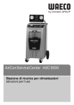
1
AirConServiceCenter ASC5000 DE 3 Klima-Service-Station Bedienungsanleitung EN 59 Air conditioning service unit Operating manual ES 119 Estación de mantenimiento de aire acondicionado Instrucciones de uso FR 180 Poste de service climatisation Notice d'utilisation RU 242 Станция по обслуживанию кондиционеров Инструкция по эксплуатации ASC5000 Inhaltsangabe DE 1 Zu dieser Bedienungsanleitung . . . . . . . . . . . . . . . . . . . . . . . . .5 1.1 1.2 Hotline . . . . . . . . . . . . . . . . . . . . . . . . . . . . . . . . . . . . . . . . . . . . . . . . . . . 5 Erklärung der Symbole in dieser Bedienungsanleitung . . . . . . . . . . . . . . 6 2 Sicherheit . . . . . . . . . . . . . . . . . . . . . . . . . . . . . . . . . . . . . . . . . . .7 2.1 2.2 2.3 2.4 2.5 2.6 Allgemeine Sicherheitshinweise . . . . . . . . . . . . . . . . . . . . . . . . . . . . . . . 7 Sicherheit beim Betrieb des Gerätes . . . . . . . . . . . . . . . . . . . . . . . . . . . . 8 Sicherheit im Umgang mit dem Kältemittel . . . . . . . . . . . . . . . . . . . . . . . 9 Betriebliche Maßnahmen beim Einsatz des Geräts. . . . . . . . . . . . . . . . 10 Warnhinweise auf dem AirConServiceCenter. . . . . . . . . . . . . . . . . . . . 10 Sicherheitsvorrichtungen . . . . . . . . . . . . . . . . . . . . . . . . . . . . . . . . . . . . 11 3 Lieferumfang. . . . . . . . . . . . . . . . . . . . . . . . . . . . . . . . . . . . . . . .11 4 Zubehör . . . . . . . . . . . . . . . . . . . . . . . . . . . . . . . . . . . . . . . . . . . .12 5 Bestimmungsgemäße Verwendung . . . . . . . . . . . . . . . . . . . . .12 6 Das AirConServiceCenter im Überblick. . . . . . . . . . . . . . . . . .13 6.1 6.2 Vorderseite . . . . . . . . . . . . . . . . . . . . . . . . . . . . . . . . . . . . . . . . . . . . . . 13 Rückseite und Seitenansicht . . . . . . . . . . . . . . . . . . . . . . . . . . . . . . . . . 14 7 Erste Inbetriebnahme. . . . . . . . . . . . . . . . . . . . . . . . . . . . . . . . .15 7.1 7.2 7.3 7.4 7.5 7.6 7.7 7.8 7.9 7.10 Ablauf der internen Dichtheitsprüfung ASC5000. . . . . . . . . . . . . . . . . . 15 Aufstellen und Einschalten . . . . . . . . . . . . . . . . . . . . . . . . . . . . . . . . . . 15 Stand-by-Menü . . . . . . . . . . . . . . . . . . . . . . . . . . . . . . . . . . . . . . . . . . . 16 Sprachauswahl . . . . . . . . . . . . . . . . . . . . . . . . . . . . . . . . . . . . . . . . . . . 17 Firmendaten eingeben. . . . . . . . . . . . . . . . . . . . . . . . . . . . . . . . . . . . . . 17 Datum und Uhrzeit eingeben . . . . . . . . . . . . . . . . . . . . . . . . . . . . . . . . . 18 Vorgabewerte ändern . . . . . . . . . . . . . . . . . . . . . . . . . . . . . . . . . . . . . . 19 Behälter für Öle und UV-Additiv einsetzen . . . . . . . . . . . . . . . . . . . . . . 20 Behältergröße eingeben . . . . . . . . . . . . . . . . . . . . . . . . . . . . . . . . . . . . 21 Auffüllen des internen Kältemittelbehälters . . . . . . . . . . . . . . . . . . . . . . 22 8 Betrieb . . . . . . . . . . . . . . . . . . . . . . . . . . . . . . . . . . . . . . . . . . . . .24 8.1 8.2 8.3 8.4 8.5 8.6 8.7 8.8 Schnellstart . . . . . . . . . . . . . . . . . . . . . . . . . . . . . . . . . . . . . . . . . . . . . . 24 Benutzercodes. . . . . . . . . . . . . . . . . . . . . . . . . . . . . . . . . . . . . . . . . . . . 25 Persönliche Datenbank anlegen . . . . . . . . . . . . . . . . . . . . . . . . . . . . . . 28 Kältemittelverbrauch auf USB-Stick übertragen . . . . . . . . . . . . . . . . . . 29 Kältemittelverbrauch auf dem Display anzeigen . . . . . . . . . . . . . . . . . . 31 Klimaanlagentest ohne Kältemittelservice . . . . . . . . . . . . . . . . . . . . . . . 32 Einzelne Prozesse . . . . . . . . . . . . . . . . . . . . . . . . . . . . . . . . . . . . . . . . . 34 Klimaanlage spülen . . . . . . . . . . . . . . . . . . . . . . . . . . . . . . . . . . . . . . . . 38 3 ASC5000 9 Servicearbeiten . . . . . . . . . . . . . . . . . . . . . . . . . . . . . . . . . . . . . .41 9.1 9.2 9.3 9.4 9.5 9.6 9.7 9.8 9.9 9.10 9.11 Dichtheitsprüfung . . . . . . . . . . . . . . . . . . . . . . . . . . . . . . . . . . . . . . . . . .41 Nullpunktüberprüfung der Ölwaagen . . . . . . . . . . . . . . . . . . . . . . . . . . .41 Trockner-Filter wechseln . . . . . . . . . . . . . . . . . . . . . . . . . . . . . . . . . . . .43 Wartung Filter. . . . . . . . . . . . . . . . . . . . . . . . . . . . . . . . . . . . . . . . . . . . .44 Drucksensor kalibrieren . . . . . . . . . . . . . . . . . . . . . . . . . . . . . . . . . . . . .46 Vakuumpumpenöl wechseln . . . . . . . . . . . . . . . . . . . . . . . . . . . . . . . . .47 Zählerstände . . . . . . . . . . . . . . . . . . . . . . . . . . . . . . . . . . . . . . . . . . . . .50 Füllmengenkorrektur bei längeren Serviceschläuchen . . . . . . . . . . . . .51 Druckerpapier erneuern . . . . . . . . . . . . . . . . . . . . . . . . . . . . . . . . . . . . .52 Softwareupdate über USB durchführen . . . . . . . . . . . . . . . . . . . . . . . . .52 Reinigung und Pflege . . . . . . . . . . . . . . . . . . . . . . . . . . . . . . . . . . . . . . .54 10 Entsorgung . . . . . . . . . . . . . . . . . . . . . . . . . . . . . . . . . . . . . . . . .54 10.1 Entsorgung der rückgewonnenen Flüssigkeiten . . . . . . . . . . . . . . . . . .54 10.2 Verpackungsmaterial entsorgen. . . . . . . . . . . . . . . . . . . . . . . . . . . . . . .54 10.3 Entsorgung des Altgerätes . . . . . . . . . . . . . . . . . . . . . . . . . . . . . . . . . . .54 4 11 Was tun, wenn? . . . . . . . . . . . . . . . . . . . . . . . . . . . . . . . . . . . . .55 12 Technische Daten . . . . . . . . . . . . . . . . . . . . . . . . . . . . . . . . . . . .58 DE ASC5000 1 Zu dieser Bedienungsanleitung Zu dieser Bedienungsanleitung Diese Bedienungsanleitung beschreibt die Klima-Service-Station (AirConServiceCenter) ASC5000. Diese Bedienungsanleitung richtet sich an Personen, die Wartungen an Fahrzeug-Klimaanlagen durchführen und hierzu die entsprechenden Fachkenntnisse besitzen. Diese Bedienungsanleitung enthält alle erforderlichen Hinweise für einen sicheren und effektiven Betrieb der Klima-Service-Station. Bevor Sie das Gerät zum ersten Mal in Betrieb nehmen, lesen Sie diese Bedienungsanleitung aufmerksam durch. Beachten Sie darüber hinaus auch: Das Schulungshandbuch „Fahrzeugklimatisierung – Technische Grundlagen“ von Dometic WAECO Die Informationsbroschüre „Fahrzeugklimatisierung – Gesetzliche Grundlagen“ von Dometic WAECO Hinweise der Kältemittelhersteller Hinweise auf den Umgang mit brennbaren Gasen, z. B. vom Kältemittelhersteller Eventuell in Ihrem Betrieb vorhandene, spezielle Hinweise zur Wartung von Fahrzeug-Klimaanlagen Bewahren Sie diese Bedienungsanleitung in der Ablage des AirConServiceCenters auf, damit Sie bei Bedarf schnell die gewünschte Information erhalten. 1.1 Hotline Wenn Sie weitere Informationen über das AirConServiceCenter benötigen, die Sie in dieser Bedienungsanleitung nicht finden, setzen Sie sich bitte mit der Hotline in Verbindung: Tel.: +49 (0) 25 72 / 8 79-1 91 DE 5 Zu dieser Bedienungsanleitung 1.2 ! ! A I ASC5000 Erklärung der Symbole in dieser Bedienungsanleitung WARNUNG! Sicherheitshinweis: Nichtbeachtung kann zu Tod oder schwerer Verletzung führen. VORSICHT! Sicherheitshinweis: Nichtbeachtung kann zu Verletzungen führen. ACHTUNG! Nichtbeachtung kann zu Materialschäden führen und die Funktion des Produktes beeinträchtigen. HINWEIS Ergänzende Informationen zur Bedienung des Produktes. Nur fachkundiges Personal darf mit diesem Gerät arbeiten. 6 Format Bedeutung Beispiel Fett Bezeichnungen, die sich auf dem Gerät befinden ENTER drücken. „Fett“ Displaymeldungen „Schnellstart“ Text Text Aufzählung in beliebiger Reihen- Sicherheitsdruckwächter Überdruckventile folge 1. Text 2. Text 3. Text Handlungsschritte, die in der dargestellten Reihenfolge durchgeführt werden müssen 1. Gerät anschließen. 2. Gerät einschalten. 3. Auswahltaste drücken. ✓ Text Ergebnis eines Handlungsschritts ✓ Gerät ist betriebsbereit. Text (1) Teile-Nummern, die sich auf die Mit der Bedientastatur (7) die Übersicht (Seite 13 und gewünschten Daten eingeben. Seite 14) beziehen Text (A) Teile-Bezeichnungen, die sich auf die im Arbeitsschritt dargestellten Bilder beziehen Filterpatrone (E) auf der linken Seite ausbauen. DE ASC5000 2 Sicherheit Sicherheit Der Hersteller übernimmt keine Haftung für Schäden aufgrund folgender Punkte: Montage- oder Anschlussfehler Beschädigungen am Produkt durch mechanische Einflüsse und Überspannungen Veränderungen am Produkt ohne ausdrückliche Genehmigung vom Hersteller Verwendung für andere als die in der Anleitung beschriebenen Zwecke und Betriebsmittel Reparatur des Servicegerätes von nicht geschultem Personal 2.1 Allgemeine Sicherheitshinweise Das AirConServiceCenter darf ausschließlich durch Personal verwendet werden, das eine geeignete technische Ausbildung nachweisen kann und die Wirkungsweise und Grundprinzipien des AirConServiceCenters, von Kühl- oder Klimaanlagen sowie von Kältemittel kennt. Bevor Sie das AirConServiceCenter zum ersten Mal in Betrieb nehmen, lesen Sie diese Bedienungsanleitung aufmerksam durch. Benutzen Sie dieses Gerät nur für den angegebenen Verwendungszweck. Führen Sie keine Änderungen oder Umbauten am AirConServiceCenter durch. Wartungsarbeiten an der Fahrzeugklimaanlage dürfen nicht bei betriebswarmen Motor durchgeführt werden. Für Wartungen an der Fahrzeugklimaanlage muss die Oberflächentemperatur von Anbauteilen oder umgebender Teile kleiner als 405 °C sein. DE 7 Sicherheit 2.2 ASC5000 Sicherheit beim Betrieb des Gerätes Setzen Sie das Gerät nicht bei starker Feuchtigkeit ein. Betreiben Sie bei Regen das Gerät nicht im Freien. Betreiben Sie das Gerät nicht in der Nähe von Wärmequellen (z. B. Heizungen) oder in direktem Sonnenlicht. Betreiben Sie das AirConServiceCenter nicht in explosionsgefährdeter Umgebung (zum Beispiel nicht im Batterieladeraum oder der Lackierkabine), siehe Betriebssicherheitsverordnung BGR 157/TRG 250, 280, 316. Nehmen Sie das AirConServiceCenter nicht in Betrieb, wenn es beschädigt ist. Überprüfen Sie vor jeder Inbetriebnahme oder vor dem Nachfüllen des AirConServiceCenters, ob das Gerät und alle Serviceschläuche unbeschädigt sind und ob alle Ventile geschlossen sind. Stellen Sie das Gerät stets auf einem ebenen Boden auf und stellen Sie die Vorderräder fest. Verwenden Sie zum Nachfüllen des AirConServiceCenters nur zugelassene Kältemittelflaschen mit Sicherheitsventil. Entleeren Sie die Serviceschläuche, bevor Sie die Anschlüsse lösen. Verwenden Sie ausschließlich das Kältemittel R-1234yf. Wird das Kältemittel mit anderen Kältemitteln gemischt, kann dies zu Schäden am AirConServiceCenter beziehungsweise an der Fahrzeug-Klimaanlage führen. Verwenden Sie ausschließlich WAECO UV-Additive. Werden andere UV-Additive eingesetzt, kann dies zu Schäden am AirConServiceCenter führen. Es entfällt jegliche Garantie. Stellen Sie vor dem Ausschalten des AirConServiceCenters sicher, dass das gewählte Programm beendet ist und dass alle Ventile geschlossen sind. Sonst kann Kältemittel austreten. Benutzen Sie immer den Hauptschalter des AirConServiceCenters zum Ein- bzw. Ausschalten. Lassen Sie das Gerät nicht unbeaufsichtigt, solange es eingeschaltet ist. Die Wartung und Reparatur der Geräts darf nur durch qualifiziertes und authorisiertes Personal von geeigneten und zertifizierten Fachfirmen vorgenommen werden. Füllen Sie keine Druckluft in die Kältemittelleitungen des AirConServiceCenters oder einer Fahrzeug-Klimaanlage. Ein Gemisch aus Druckluft und Kältemittel kann entzündlich oder explosiv sein. 8 DE ASC5000 2.3 Sicherheit Sicherheit im Umgang mit dem Kältemittel Wartungsarbeiten an der Fahrzeugklimaanlage dürfen nicht bei betriebswarmen Motor durchgeführt werden. Für Wartungen an der Fahrzeugklimaanlage muss die Oberflächentemperatur von Anbauteilen oder umgebender Teile kleiner als 405 °C sein. Tragen Sie persönliche Schutzausrüstung (Schutzbrille und Schutzhandschuhe) und vermeiden Sie Körperkontakt mit dem Kältemittel. Körperkontakt mit dem Kältemittel entzieht dem Körper Wärme, so dass es an den betroffenen Stellen zu Erfrierungen kommen kann. Achten Sie darauf, dass während des Betriebs, des Auffüllens oder Entleerens von Kältemittel sowie während Reparatur- und Servicearbeiten kein Kältemittel austreten und in die Umwelt gelangen kann. Dadurch werden nicht nur Umweltschutzgesetze eingehalten. Es wird auch vermieden, dass durch das Vorhandensein von Kältemittel in der Umgebung des Geräts das Auffinden von Lecks am Fahrzeug oder am Gerät erschwert wird oder unmöglich ist. Atmen Sie die Kältemitteldämpfe nicht ein. Die Kältemitteldämpfe sind zwar ungiftig, sie verdrängen aber den für die Atmung erforderlichen Sauerstoff. Kältemittel darf nicht im Bereich von tiefer gelegenen Räumen (z. B. Montagegruben, Sickerschächte) verwendet werden. Das Kältemittel ist schwerer als Sauerstoff und verdrängt daher den für die Atmung erforderlichen Sauerstoff. Bei Arbeiten in ungelüfteten Montagegruben kann es zu Sauerstoffmangel kommen. Treffen Sie Vorkehrungen, damit ausgetretenes Kältemittel nicht in die Kanalisation gelangen kann. Spezielle Informationen über das Kältemittel R-1234yf und über Sicherheitsmaßnahmen sowie den Schutz von Personen und Gegenständen einschließlich des Brandschutzes können Sie den Sicherheitsblättern des Kältemittelherstellers entnehmen. DE 9 Sicherheit 2.4 ASC5000 Betriebliche Maßnahmen beim Einsatz des Geräts Der Betreiber muss gemäß TRG 402 für jede Füllanlage (AirConServiceCenter) eine Betriebsanweisung erstellen. Anhand dieser Betriebsanweisung müssen die Beschäftigten im Umgang mit dem Gerät unterwiesen werden. Der Betreiber muss dafür Sorge tragen, dass die Beschäftigten mindestens einmal jährlich in folgenden Punkten unterwiesen werden: besondere Gefahren im Umgang mit Druckgasen Sicherheitsvorschriften beim Umgang mit Druckgasen Gesundheitsmaßnahmen beim Umgang mit Druckgasen Bedienung des Geräts und Ausführung von Servicearbeiten am Gerät Der Betreiber des Geräts muss dafür sorgen, dass Personal, das mit Service- und Reparaturarbeiten sowie der Dichtheitsprüfung beauftragt wird, zertifiziert ist im Umgang mit Kältemitteln und Füllanlagen. Die Zertifizierung sowie Kenntnisse der geltenen Vorschriften und Normen können in einer Schulung, z. B. bei einer Handwerkskammer, einer Industrie- und Handelskammer oder bei einer anderen anerkannten Schulungsstätte, erworben werden. 2.5 Warnhinweise auf dem AirConServiceCenter Schließen Sie das Gerät nur an eine Steckdose mit 230 V/50 Hz Wechselstrom an! Schützen Sie das Gerät vor Regen! Tragen Sie beim Umgang mit Kältemittel Handschuhe! Tragen Sie beim Umgang mit Kältemittel eine Schutzbrille! Warnung vor feuergefährlichen Stoffen 10 DE ASC5000 2.6 Lieferumfang Sicherheitsvorrichtungen Sicherheitsdruckwächter: Schaltet den Kompressor aus, wenn der normale Betriebsdruck überschritten wird. Überdruckventil: Zusätzliche Sicherheitsvorrichtung, um ein Bersten von Leitungen oder Behältern zu verhindern, falls der Überdruck trotz des Sicherheitsdruckwächters weiter steigt. Lüfterüberwachung: Prüft laufend, ob der rückwärtige Lüfter ausreichend Luft fördert. 3 Lieferumfang Das AirConServiceCenter und das mitgelieferte Zubehör wurden vor dem Versand sorgfältig kontrolliert. Kontrollieren Sie nach der Anlieferung, ob alle unten genannten Teile vorhanden und unbeschädigt sind. Informieren Sie bei fehlenden oder beschädigten Teilen umgehend das für den Transport verantwortliche Unternehmen. Bezeichnung Schutzbrille / Schutzhandschuhe Bedienungsanleitung A DE ACHTUNG! Für den sicheren Betrieb benötigen Sie das Kältemittel R-1234yf (nicht im Lieferumfang enthalten). Zur Zeit werden Kältemittelflaschen mit unterschiedlichen Anschlussgewinden und Adaptern geliefert; diese sind nicht im Lieferumfang enthalten. 11 Zubehör 4 ASC5000 Zubehör Als Zubehör erhältlich (nicht im Lieferumfang enthalten): 5 Bezeichnung Artikel-Nr. Altölbehälter, 500 ml 4440600033 Ersatzfilter 4440400009 Geräteschutzhaube 4445900081 Ersatz-Papierrolle für Drucker (Thermopapier) (VPE 4) 4445900088 Schutzbrille 8885400066 Schutzhandschuhe 8885400065 Vakuumpumpenöl, 1000 ml 8887200018 Bestimmungsgemäße Verwendung Das AirConServiceCenter ASC5000 (Artikelnummer: 8885200104) ist für Wartungen an Fahrzeug-Klimaanlagen bestimmt. Das Gerät ist für den kommerziellen Einsatz ausgelegt. Die Bedienung des AirConServiceCenters darf nur durch Personen erfolgen, welche die entsprechenden Fachkenntnisse zur Wartung von Klimaanlagen besitzen. Mit dem AirConServiceCenter dürfen nur Fahrzeug-Klimaanlagen gewartet werden, in denen das Kältemittel R-1234yf verwendet wird. Andere Kältemittel sind nicht zulässig. Das AirConServiceCenter ist nur für zugelassene Betriebsstoffe geeignet. 12 DE ASC5000 Das AirConServiceCenter im Überblick 6 Das AirConServiceCenter im Überblick 6.1 Vorderseite 4 1 3 5 2 16 6 15 7 14 13 8 12 11 10 9 1 Niederdruckmanometer 2 Statusleuchte Rot „Füllen“ 3 Statusleuchte Blau „Evakuieren“ 4 Statusleuchte Grün „Absaugen“ 5 Hochdruckmanometer 6 Display 7 Bedientastatur 8 Frontabdeckung 9 Feststellbare Vorderräder 10 Serviceschlauch Niederdruckanschluss (blau) DE 13 Das AirConServiceCenter im Überblick ASC5000 11 Serviceschlauch Hochdruckanschluss (rot) 12 Servicekupplung für Hochdruckanschluss (rot) 13 Servicekupplung für Niederdruckanschluss (blau) 14 Drucker 15 USB-Anschluss 16 Anzeigeeinheit 6.2 Rückseite und Seitenansicht 20 17 21 18 19 17 Behälter für Frischöl 18 Behälter für UV-Additiv 19 Altölbehälter 20 Hauptschalter 21 Lüfter 14 DE ASC5000 Erste Inbetriebnahme 7 Erste Inbetriebnahme 7.1 Ablauf der internen Dichtheitsprüfung ASC5000 Täglich wird die interne Gerätedruckprüfung automatisch durchgeführt. Als erstes wird getestet, ob die Serviceschläuche an eine Klimaanlage angeschlossen sind oder ob evtl. die Servicekuppler nicht montiert sind. Wenn noch Druck auf den Schläuchen vorhanden ist, wird ein Fehler ausgegeben und das Kältemittel abgesaugt. Danach erfolgt die Vakuumprüfung. Hierbei werden mehrere Teile des Gerätes evakuiert. Nach erfolgreicher Vakuumprüfung werden Teile des Gerätes mit Kältemittel beaufschlagt – jetzt erfolgt ein 6-minütiger Drucktest, bei dem sämtliche zugehörige Magnetventile geöffnet bleiben, um sofort einen Druckabfall feststellen zu können. Nach erfolgreichem Ablauf wird das Kältemittel abgesaugt und das Gerät steht für Servicearbeiten zur Verfügung. 7.2 Aufstellen und Einschalten 1. AirConServiceCenter zum Arbeitsplatz fahren und Vorderräder (9) feststellen. I HINWEIS Das Gerät muss während des Einsatzes fest auf einem waagerechten, ebenen Untergrund stehen, damit die Messungen korrekt durchgeführt werden können. 2. AirConServiceCenter an das Stromnetz anschließen. 3. Zum Einschalten, Hauptschalter (21) auf I stellen. Für 35 Sekunden läuft die Einschaltverzögerung und das Gehäuse wird belüftet. Danach zeigt das Display (6) für einige Sekunden die Software-Versionsnummer: WAECO INTERNATIONAL ASC 5000 SW DB SN BML10024 lhd10026 XXXXXX „SW“: Softwarestand „DB“: Datenbank „SN“: Seriennummer Dann wird folgende Meldung angezeigt: interner Tankdruck Warten DE 15 Erste Inbetriebnahme ASC5000 ✓ Anschließend läuft ein Software-Test des AirConServiceCenters. Software test. Warten ✓ Danach läuft eine Dichtheitsprüfung. Dichtheitsprüfung Warten ✓ Zum Abschluss des Startvorgangs zeigt das AirConServiceCenter folgendes: Kältemittel Frischöl UV Additive 11:56:35 I 7.3 g. ml ml XXXX XXX XXX 10/03/11 HINWEIS Errorcodes, die bei der Erstinbetriebnahme auftreten (siehe Seite 56), ignorieren und mit ENTER übergehen. Stand-by-Menü Das Stand-by-Menü informiert über aktuelle Bestandsmengen sowie Zeiteinstellungen des AirConServiceCenters. Es werden angezeigt: Bestandsmenge Kältemittel Bestandsmenge Frischöl Bestandsmenge UV-Additive Uhrzeit Datum 16 DE ASC5000 7.4 Erste Inbetriebnahme Sprachauswahl 1. Pfeiltasten oder drücken, um ins Grundmenü zu gelangen. 2. Im Grundmenü mit den Pfeiltasten oder „Weitere Menues“ wählen: Schnellstart Einzelne Prozesse Weitere Menues ENTER-OK 3. 4. 5. 6. 7. 8. 9. 7.5 Zur Bestätigung ENTER drücken. Mit der Pfeiltaste „Service“ wählen. Zur Bestätigung ENTER drücken. Passwort „5264“ eingeben. Mit den Pfeiltasten oder die gewünschte Sprache wählen. Zur Bestätigung ENTER drücken. STOP drücken. Die gewählte Sprache ist aktiv und das Stand-byMenü wird angezeigt. Firmendaten eingeben Die Firmendaten werden mit jedem Serviceprotokoll ausgedruckt. 1. Im Grundmenü mit den Pfeiltasten oder „Weitere Menues“ wählen: Schnellstart Einzelne Prozesse Weitere Menues ENTER-OK 2. 3. 4. 5. 6. DE Zur Bestätigung ENTER drücken. Mit der Pfeiltaste „Service“ wählen. Zur Bestätigung ENTER drücken. Passwort „3282“ eingeben. Die Firmendaten werden in der dritten Zeile des Displays (6) angezeigt. Es können fünf Zeilen mit je 20 Zeichen eingegeben werden. Im Display erscheint die Zahl der angezeigten Firmendaten-Zeile hinter der Meldung „Firmendaten eingeben“ („01“ bis „05“). Mit den Pfeiltasten oder wird die gewünschte FirmendatenZeile ausgewählt. 17 Erste Inbetriebnahme ASC5000 7. Mit der Bedientastatur (7) und den Pfeiltasten die gewünschten Daten eingeben: Zum Umschalten zwischen Groß- oder Kleinbuchstaben, die InfoTaste drücken. Zum Löschen einzelner Zeichen, Taste C kurz drücken. Zum Löschen der angezeigten Zeile, Taste C länger drücken. 8. Zur Bestätigung ENTER drücken. 9. STOP drücken. Die eingestellten Daten sind aktiv. 10. Erneut STOP drücken, um in das Stand-by-Menü zu gelangen. 7.6 Datum und Uhrzeit eingeben Datum und Uhrzeit werden zusammen mit den Firmendaten mit jedem Serviceprotokoll ausgedruckt. 1. Im Grundmenü mit den Pfeiltasten oder „Weitere Menues“ wählen: Schnellstart Einzelne Prozesse Weitere Menues ENTER-OK 2. 3. 4. 5. 6. Zur Bestätigung ENTER drücken. Mit der Pfeiltaste „Service“ wählen. Zur Bestätigung ENTER drücken. Passwort „8463“ eingeben. Mit der Bedientastatur und den Pfeiltasten die gewünschten Daten eingeben. 7. Zur Bestätigung ENTER drücken. 8. STOP drücken, um in das Stand-by-Menü zu gelangen. 18 DE ASC5000 7.7 Erste Inbetriebnahme Vorgabewerte ändern Das AirConServiceCenter hat voreingestellte Werte für die wichtigsten Servicearbeiten. Diese Vorgabewerte erscheinen automatisch beim Aufrufen der entsprechenden Menüs. Die folgenden Vorgabewerte können an den speziellen Bedarf angepasst werden: Parameter Vorgabe ab Werk Wartezeit für den Druckanstieg Min. 5 Vakuumzeit Min. 20 Vakuumkontrollzeit Min. 4 Frischöl ml. (Extramenge) 0 UV-Additive ml. 0 Füllmenge g. 500 Absaugmenge ausdrucken? Ja 1. Im Grundmenü mit den Pfeiltasten oder „Weitere Menues“ wählen: Schnellstart Einzelne Prozesse Weitere Menues ENTER-OK 2. 3. 4. 5. 6. Zur Bestätigung ENTER drücken. Mit der Pfeiltaste „Service“ wählen. Zur Bestätigung ENTER drücken. Passwort „7388“ eingeben. Mit der Bedientastatur und den Pfeiltasten die gewünschten Daten eingeben. 7. Zur Bestätigung ENTER drücken. 8. STOP drücken, um in das Stand-by-Menü zu gelangen. DE 19 Erste Inbetriebnahme 7.8 I ASC5000 Behälter für Öle und UV-Additiv einsetzen HINWEIS Verwenden Sie ausschließlich für R-1234yf freigegebene Öle und UV-Additive. Beachten Sie die Hinweise des Fahrzeugherstellers. Die aktuellen Bestandsmengen werden im Stand-by-Menü angezeigt. 1. Behälter an den Schnellverschlüssen aufstecken: – Behälter für frisches Öl (17) – Behälter für UV-Additiv (18) und – Altölbehälter (19) 17 18 19 2. Behältergröße für Frischöl und UV-Kontrastmittel eingeben (siehe Kapitel „Behältergröße eingeben” auf Seite 21). 20 DE ASC5000 7.9 Erste Inbetriebnahme Behältergröße eingeben Für Frischöl und UV-Kontrastmittel können Behälter (Zubehör) mit 500 ml (B) oder 250 ml (C) verwendet werden. Die entsprechende Behältergröße muss in das AirConServiceCenter eingegeben werden. A ACHTUNG! Verwenden Sie ausschließlich freigegebene R-1234yf-Öle. B C 1. Im Grundmenü mit den Pfeiltasten oder „Weitere Menues“ wählen: Schnellstart Einzelne Prozesse Weitere Menues ENTER-OK 2. 3. 4. 5. 6. Zur Bestätigung ENTER drücken. Mit der Pfeiltaste „Service“ wählen. Zur Bestätigung ENTER drücken. Passwort „2688“ eingeben. Mit den Pfeiltasten die gewünschten Felder aktivieren (die dunklen Felder sind aktiv). 7. Zur Bestätigung ENTER drücken. 8. STOP drücken, um in das Stand-by-Menü zu gelangen. DE 21 Erste Inbetriebnahme 7.10 ASC5000 Auffüllen des internen Kältemittelbehälters Wenn das AirConServiceCenter das erste Mal in Betrieb genommen wird, muss der interne Kältemittelbehälter aus einer externen Kältemittelflasche mit mindestens 2000 g Kältemittel aufgefüllt werden. Das Gerät zeigt die Fehlermeldung 12. Zur Bestätigung STOP drücken. I HINWEIS Beachten Sie auch die Hinweise auf den Kältemittelflaschen! Kältemittelflaschen für das Kältemittel R-1234yf haben Linksgewinde! Die aktuellen Bestandsmengen werden im Stand-by-Menü angezeigt. Es werden drei verschiedene Arten von Kältemittelflaschen angeboten: Kältemittelflaschen ohne Steigrohr Diese Kältemittelflaschen besitzen einen Anschluss. Beim Befüllen des AirConServiceCenters muss sich der Anschluss unten befinden (Flasche auf den Kopf stellen). Kältemittelflaschen mit Steigrohr Diese Kältemittelflaschen besitzen einen Anschluss. Beim Befüllen des AirConServiceCenters muss sich der Anschluss oben befinden (Flasche aufrecht stellen). Kältemittelflaschen mit Steigrohr: Diese Kältemittelflaschen besitzen zwei Anschlüsse. Zum Befüllen des AirConServiceCenters wird der mit L (= liquid / flüssig) gekennzeichnete Anschluss benutzt. Beim Befüllen des AirConServiceCenters muss sich der Anschluss oben befinden (Flasche aufrecht stellen). 1. Im Grundmenü mit den Pfeiltasten oder „Weitere Menues“ wählen: Schnellstart Einzelne Prozesse Weitere Menues ENTER-OK 2. Zur Bestätigung ENTER drücken. 3. Mit den Pfeiltasten oder „Int. Flasche füllen“ wählen: Int.Flasche füllen A/C spülen. Nullpunkt Waagen Service 4. Zur Bestätigung ENTER drücken. 22 DE ASC5000 Erste Inbetriebnahme 5. Zum weiteren Vorgehen den Hinweisen im Display und hier folgen: HD-Schlauch mit ext. Flasche verbinden und Ventile öffnen ENTER-OK STOP-EXIT Zur Bestätigung ENTER drücken. Gewünschte Menge eingeben! g. 13620 ENTER-OK STOP-EXIT Das Display zeigt die max. auffüllbare Menge Kältemittel an. Gewünschte Menge eingeben und mit ENTER bestätigen. Der interne Kältemittelbehälter wird befüllt. Das Ende des Füllvorgangs wird durch ein akustisches Signal bestätigt. Ventile schließen und mit ENTER bestätigen. 6. Nach dem Befüllen wird die Menge des Kältemittels im internen Behälter angezeigt. STOP drücken, um das Menü zu verlassen. Um in das Stand-by-Menü zu gelangen, noch einmal STOP drücken. Das Gerät ist nun betriebsbereit. DE 23 Betrieb 8 A 8.1 I ASC5000 Betrieb ACHTUNG! Während der Klimaservice durchgeführt wird, müssen Motor und Klimaanlage abgestellt sein. Schnellstart HINWEIS Mit dem Menü „Schnellstart“ wird ein vollautomatischer Klimaservice durchgeführt. Es muss nur die Füllmenge nach dem Füllmengenaufkleber im Fahrzeug eingegeben werden. Im Menü „Schnellstart“ werden automatisch hintereinander ausgeführt: Absaugen des Kältemittels Recycling des Kältemittels (Reinheit entspricht SAE J 2099) Prüfung des Druckanstiegs Ablassen des Altöls Evakuieren der Anlage Dichtheitsprüfung / Vakuumkontrolle Auffüllen von Frischöl in der benötigten Menge Einfüllen von UV-Additiv Einfüllen von Kältemittel Im Anschluss an jeden durchgeführten Prozess wird ein Serviceprotokoll gedruckt. Nur wenn ein Prozess erfolgreich abgeschlossen wurde, wird der darauf folgende Prozess begonnen. 1. Die Serviceschläuche des AirConServiceCenters zunächst mit der Fahrzeug-Klimaanlage verbinden und die Servicekupplungen öffnen. 2. Pfeiltaste oder drücken, um ins Grundmenü zu gelangen. 3. Im Grundmenü mit den Pfeiltasten oder „Schnellstart“ wählen: Schnellstart Einzelne Prozesse Weitere Menues ENTER-OK 4. Zur Bestätigung ENTER drücken. 5. Mit der Bedientastatur (7) und den Pfeiltasten Fahrzeugdaten eingeben. 6. Zur Bestätigung ENTER drücken. 7. Kältemittel-Füllmenge eingeben. Den entsprechenden Wert von dem Füllmengenaufkleber im Fahrzeug entnehmen und mit der Bedientastatur (7) und den Pfeiltasten eingeben und ENTER drücken. 24 DE ASC5000 Betrieb 8. Mit den Pfeiltasten oder wählen, ob die Klimaanlage über zwei Anschlüsse verfügt (Hoch- und Niederdruck) oder nur über einen Anschluss (Hochdruck oder Niederdruck). Klimaanlage ND/HD Klimaanlage nur HD Klimaanlage nur ND ENTER-OK STOP-EXIT Mit ENTER bestätigen. ✓ Der vollautomatische Klimaservice wird gestartet. ✓ Nachdem der Klimaservice beendet ist, erscheint die Aufforderung die Serviceschläuche (10) und (11) des AirConServiceCenters von der Fahrzeug-Klimaanlage abzukuppeln. 9. Serviceschläuche (10) und (11) abkuppeln und zur Bestätigung ENTER drücken. Die Serviceschläuche werden nun geleert. Anschließend ist das Gerät für weitere Einsätze betriebsbereit. 10. Ventilkappen der Fahrzeug-Klimaanlage auf die Anschlüsse aufschrauben. 8.2 Benutzercodes Es besteht die Möglichkeit, die Klima-Service-Station mit persönlichen Benutzercodes vor unbefugtem Zugriff zu schützen. Wenn die Funktion aktiviert ist, wird nach dem Einschalten der Benutzercode abgefragt, ohne den man die Station nicht mehr starten kann. Es können bis zu 10 verschiedene Benutzer mit individuellen Codes angelegt werden. 8.2.1 Benutzercodes anlegen 1. Im Grundmenü mit den Pfeiltasten oder „Weitere Menues“ wählen: Schnellstart Einzelne Prozesse Weitere Menues ENTER-OK 2. Zur Bestätigung ENTER drücken. 3. Mit der Pfeiltaste „Service“ wählen und mit ENTER bestätigen: A/C spülen. Nullpunkt Waagen Service ENTER-OK STOP-EXIT DE 25 Betrieb ASC5000 4. Passwort „9786“ eingeben und mit ENTER bestätigen, um ins Administratormenü „ADM“ zu gelangen: Service ---- 5. Administratorcode „0000“ (Werkseinstellung) eingeben und mit ENTER bestätigen: Insert ADM Code ---- I HINWEIS Aus Sicherheitsgründen muss jedes Mal ein neuer Administratorcode gewählt werden, der nicht „0000“ sein darf, da die komplette Funktion sonst wieder deaktiviert wird. Mit Hilfe des Administratorcodes können Benutzer angelegt werden. 6. Neuen Administratorcode eingeben: ADM AREA Insert new code ---- 7. Neuen Administratorcode bestätigen: ADM AREA Confirm new code ---- 8. Mit den Pfeiltasten oder den jeweiligen Benutzer wählen: ADM AREA User number 1 9. Den vierstelligen individuellen Benutzercode anlegen (Wird hier ein Code angelegt, kann das Gerät nur noch mit diesem Code in Betrieb genommen werden). ADM AREA User number Insert new code 1 ---- 10. Neuen Benutzercode bestätigen: ADM AREA User number Confirm new code 1 ---- 26 DE ASC5000 I Betrieb HINWEIS Mit der gelben Infotaste lässt sich zwischen Groß- und Kleinschreibung umschalten. 11. Den dazugehörigen Benutzernamen eingeben und die Eingabe mit ENTER bestätigen: ADM AREA User number User name Max Mustermann ADM AREA User number Max Mustermann I 8.2.2 1 1 HINWEIS Der User ist angelegt und das Menü wechselt wieder in die BenutzerAuswahl. Sie können nun einen weiteren Benutzer anlegen oder mit STOP das Menü verlassen. Benutzercode eingeben Beim Einschalten der Klima-Service-Station werden die Gerätedaten auf dem Display angezeigt. Sind Benutzercodes angelegt, so muss nun ein Code eingegeben werden, um die Station freizugeben. 1. Den jeweiligen Benutzercode eingeben. ENTER USER CODE ---- Bei Eingabe eines falschen Benutzercodes wird folgender Fehlermeldung angezeigt. WRONG CODE Nach erfolgreicher Eingabe wird die Station freigeschaltet und fährt hoch. Der Name des Benutzers wird angezeigt: Max Mustermann DE 27 Betrieb 8.3 ASC5000 Persönliche Datenbank anlegen In dieser Datenbank können bis zu 100 kundenspezifische Fahrzeuge mit den dazugehörigen Füllmengen angelegt werden. 1. Im Grundmenü mit den Pfeiltasten oder „Schnellstart“ wählen: Schnellstart Einzelne Prozesse Weitere Menues ENTER-OK 2. Zur Bestätigung ENTER drücken. 3. Nach Eingabe des Fahrzeugkennzeichens (kann in diesem Fall auch freigelassen werden) mit ENTER bestätigen. KFZ-DATEN KFZ-Kenn.: 4. Mit den Pfeiltasten oder „Datenbank“ wählen und mit ENTER bestätigen. Füllmenge g 500 Datenbank ENTER-OK STOP-EXIT 5. „Personal DB“ wählen und mit ENTER bestätigen. Personal DB ALFA ROMEO ASTON MARTIN AUDI 6. In diese hier leere Datenbank mit den Pfeiltasten oder den jeweiligen Eintrag wählen und mit ENTER bestätigen. 0 1 7. Zum Ändern der Einträge gelbe Taste „Info“ drücken. 0 g --- 0 i-DB set 8. In die freien Felder die Fahrzeugdaten (Modell, Typ) eingeben und mit ENTER bestätigen. ____________ ___________________ ____________ g 28 0 ___ 0 DE ASC5000 Betrieb 9. Die Kältemittelfüllmenge eingeben und mit ENTER bestätigen. AUDI A4 (8E) 2000 - 2004 0 g. 500 ✓ Der Eintrag ist angelegt. AUDI A4 (8E) 0 1 Sie können nun einen einen weiteren Eintrag anlegen (mit den Pfeiltasten auswählen, dann wie beschrieben) oder mit der Taste „STOP“ das Menü verlassen. Die persönlichen Einträge werden auf der Platine gespeichert, nicht auf der Flash-Memory-Card! Die Einträge bleiben also auch bei einem Software-Update erhalten. Die Einträge werden chronologisch abgelegt (nicht alphanumerisch). 8.4 Kältemittelverbrauch auf USB-Stick übertragen Jedes Mal wenn ein Absaug- oder Füllvorgang (einzelner Prozess oder vollautomatisch) abgeschlossen wird, speichert die Station sämtliche zugehörigen Daten im internen Speicher. Aus diesen Daten kann ein Report generiert und auf einen USB-Stick übertragen werden. I HINWEIS Der USB-Stick muss mit dem Dateisystem FAT32 formatiert sein. Jeder Report wird in zwei Formaten gespeichert: als HTML-Datei (zum Öffnen mit einem beliebigen Internet-Browser) als XLS-Datei (zum Öffnen mit Microsoft Excel) I DE HINWEIS Der Report kann ein eigenes Logo (z. B. das Werkstatt-Logo) enthalten, wenn eine Grafik auf den USB-Stick kopiert wird, die folgende Voraussetzungen erfüllt: Dateiformat: JPEG-Format Dateiname: logo.jpg (Groß- und Kleinschreibung beachten) Bildgröße: 370 x 50 Pixel Die Firmenanschrift im Report wird aus der Station übernommen (siehe Kapitel „Firmendaten eingeben” auf Seite 17). 29 Betrieb 8.4.1 ASC5000 Report nach Jahreswechsel Nach einem Jahreswechsel meldet die Station, dass die gespeicherten Daten des vergangenen Jahres auf einen USB-Stick übertragen werden sollen. Wenn Sie die Jahresdaten auf einen USB-Stick übertragen, werden diese danach aus dem internen Speicher der Station gelöscht. 1. Den USB-Stick in den USB-Anschluss (15) stecken. 2. Den Displayanweisungen folgen. 8.4.2 Manueller Report Sie können jederzeit manuell einen Monats- oder Jahresreport auf einen USB-Stick übertragen. 1. Den USB-Stick in den USB-Anschluss (15) stecken. 2. Im Grundmenü mit den Pfeiltasten oder „Weitere Menues“ wählen: Schnellstart Einzelne Prozesse Weitere Menues ENTER-OK 3. Zur Bestätigung ENTER drücken. 4. Mit der Pfeiltaste „Service“ wählen und mit ENTER bestätigen: 5. Passwort eingeben und mit ENTER bestätigen. – „4910“: Monatsreport – „4918“: Jahresreport Falls kein USB-Stick eingesteckt ist oder dieser nicht erkannt wird, wird „Error 52“ angezeigt. 6. Mit den Pfeiltasten oder den gewünschten Eintrag wählen und mit ENTER bestätigen. 7. Den Displayanweisungen folgen. 8. Mit STOP zur vorigen Auswahl zurück wechseln. 30 DE ASC5000 8.5 Betrieb Kältemittelverbrauch auf dem Display anzeigen Die Station speichert die Daten der eingefüllten und abgesaugten Kältemittelmengen. Diese können als Jahresübersicht oder Monatsübersicht direkt ausgedruckt werden. 1. Im Grundmenü mit den Pfeiltasten oder „Weitere Menues“ wählen: Schnellstart Einzelne Prozesse Weitere Menues ENTER-OK 2. Zur Bestätigung ENTER drücken. 3. Mit der Pfeiltaste „Service“ wählen und mit ENTER bestätigen: A/C spülen. Nullpunkt Waagen Service ENTER-OK STOP-EXIT 4. Passwort „9051“ eingeben und mit ENTER bestätigen: Service ---- 5. Mit den Pfeiltasten oder das gewünschte Jahr wählen und mit ENTER bestätigen: 2012 Beispiel Von Klimaanlagen Total g. PRINT STOP-EXIT 2013 18650 „Von Klimaanlagen“ zeigt die Menge des abgesaugten Kältemittels an. Hier wurden im Jahr 2013 insgesamt 18 650 g Kältemittel mit der Station abgesaugt. Mit der Pfeiltaste wird als nächstes die Totalmenge des eingefüllten Kältemittels des entsprechenden Jahres angezeigt: Eingefüllt in A/C Total g. PRINT STOP-EXIT DE 2013 9000 31 Betrieb ASC5000 Durch Drücken der Pfeiltaste wird die Monatsübersicht im Display dargestellt: Von Klimaanlagen 01/2013 2400 g. PRINT STOP-EXIT Hier wurden im Januar 2013 insgesamt 2 400 g Kältemittel abgesaugt. In der Monatsübersicht wird die eingefüllte und abgesaugte Menge immer im Wechsel angezeigt. Die Übersicht lässt sich jederzeit durch Betätigen der Taste „ENTER“ ausdrucken. Mit der Taste „STOP“ wird die Übersicht beendet. 8.6 I Klimaanlagentest ohne Kältemittelservice HINWEIS Der Klimaanlagentest kann nur bei Fahrzeugen durchgeführt werden, die mit einem Niederdruck- und einem Hochdruckanschluss, bzw. nur mit einem Niederdruckanschluss ausgestattet sind. Wird an einer Fahrzeugklimaanlage ausschließlich ein Funktionstest durchgeführt (ohne Kältemittel abzusaugen und zu recyceln), würde nach Abschluss dieses Tests das in den Serviceschläuchen des Klimagerätes vorhandene Kältemittel dem Fahrzeugklimaanlagensystem fehlen. Der Menüpunkt „Klimaanlagentest“ wurde eingeführt um diese Verlustmenge auszugleichen. I HINWEIS Bei den bisherigen Standardfunktionsprozessen „Schnellstart“ oder „Einzelne Prozesse“ ist bereits eine Füllmengenkompensation für die Serviceschläuche vorhanden, so dass hier der abschließende Klimaanlagenfunktionstest in gewohnter Weise durchgeführt werden kann (Serviceschläuche werden vom Gerät entleert). 1. Die entsprechenden Anschlüsse des AirConServiceCenters zunächst mit der Fahrzeug-Klimaanlage verbinden und öffnen. 2. Fahrzeugmotor starten und Klimaanlage einschalten. 3. Pfeiltaste oder drücken, um ins Grundmenü zu gelangen. 4. Im Grundmenü mit den Pfeiltasten oder „Weitere Menues“ wählen: Schnellstart Einzelne Prozesse Weitere Menues ENTER-OK 5. Zur Bestätigung ENTER drücken. 32 DE ASC5000 Betrieb 6. Mit den Pfeiltasten oder „Klimaanlagentest“ wählen: Klimaanlagentest Service ENTER-OK STOP-EXIT ✓ Es erscheint die Aufforderung, die Klimaanlage zu kontrollieren: Klimaanlage kontrollieren STOP-EXIT 7. Hoch- und Niederdruck der Klimaanlage gemäß den Herstellerangaben prüfen. 8. Zum Beenden des Klimaanlagentests STOP drücken. HD-Schnellkupplung der Klimaanlage entfernen! ENTER-OK 9. HD-Schnellkupplung schließen und von der Klimaanlage entfernen. I HINWEIS Wenn Sie zum Entkoppeln der HD-Schnellkupplung den Fahrzeugmotor abgestellt haben, so starten Sie diesen erneut und schalten Sie die Klimaanlage ein. ✓ Folgende Displaymeldungen werden angezeigt. Warten ! Serviceschläuche werden geleert ! Programmende ! STOP-EXIT 10. Um den Klimaanlagentest zu beenden, Taste STOP drücken. DE 33 Betrieb 8.7 I ASC5000 Einzelne Prozesse HINWEIS Mit dem Menü „Einzelne Prozesse“ wird der Klimaservice Schritt für Schritt durchgeführt. Es können dieselben Prozesse wie beim Schnellstart durchgeführt werden, einzelne Prozesse können jedoch ausgelassen werden. Außerdem können zu jedem Prozess die jeweiligen Werte individuell über die Tastatur eingegeben werden. Weiterhin können in diesem Menü Fahrzeugdaten für das Serviceprotokoll eingegeben werden. Im Menü „Einzelne Prozesse“ können die folgenden vier Prozesse einzeln ausgeführt werden: Klimaanlage entleeren: Absaugen, Recycling des Kältemittels, Prüfung des Druckanstiegs, Ablassen des Altöls. Vakuum erzeugen: Evakuieren der Anlage, Dichtheitsprüfung/ Vakuumkontrolle. Klimaanlage befüllen: Auffüllen von Frischöl, Einfüllen von UV-Additiv, Einfüllen von Kältemittel. Anschlüsse wählen: Klimaanlage hat Hoch- und Niederdruckanschluss, nur Hochdruck- oder nur Niederdruckanschluss Im Anschluss an jeden durchgeführten Prozess wird ein Serviceprotokoll gedruckt. 1. Die entsprechenden Anschlüsse des AirConServiceCenters zunächst mit der Fahrzeug-Klimaanlage verbinden und öffnen. 2. Im Grundmenü mit den Pfeiltasten oder „Einzelne Prozesse“ wählen: Schnellstart Einzelne Prozesse Weitere Menues ENTER-OK 3. Zur Bestätigung ENTER drücken. 4. Fahrzeugdaten eingeben und mit ENTER bestätigen. 34 DE ASC5000 8.7.1 Betrieb Absaugvorgang 1. Gewünschte Einstellungen wählen und mit ENTER bestätigen. Klimaanlage entleeren? Ja Nein ENTER-OK STOP-EXIT 2. Wenn „Klimaanlage entleeren“ gewählt wurde, im folgenden Menü die gewünschte Wartezeit für den Druckanstieg eingeben (Standard 1 min) und mit ENTER bestätigen, ansonsten weiter mit Kapitel „Vakuumvorgang” auf Seite 35. Wartezeit für den Druckanstieg min. 1 ENTER-OK STOP-EXIT I 8.7.2 HINWEIS Durch die Wartezeit wird sichergestellt, dass eventuell vorhandenes Restkältemittel verdampfen und danach abgesaugt werden kann. Das verdampfende Restkältemittel löst einen Druckanstieg aus. Vakuumvorgang 1. Gewünschte Einstellungen wählen und mit ENTER bestätigen. Vakuum erzeugen Ja Nein ENTER-OK STOP-EXIT 2. Wenn „Vakuum erzeugen“ gewählt wurde, die gewünschte Vakuumzeit eingeben (Standard 20 min), ansonsten weiter mit Kapitel „Füllvorgang” auf Seite 36. 3. Mit der Pfeiltaste die gewünschte Vakuumkontrollzeit eingeben. 4. Beide Einstellungen mit ENTER bestätigen. Vakuumzeit Vakuumkontrollzeit min. 20 min. 4 ENTER-OK STOP-EXIT I DE HINWEIS Die Klimaanlage wird durch die Vakuumpumpe tiefentleert. Dies dient dazu, eventuell vorhandene Fremdgase oder Feuchtigkeit zu entfernen und die Klimaanlage auf den Füllvorgang vorzubereiten. 35 Betrieb 8.7.3 ASC5000 Füllvorgang 1. Gewünschte Einstellungen wählen und mit ENTER bestätigen. Klimaanlage befüllen? Ja Nein ENTER-OK STOP-EXIT 2. Wenn „Klimaanlage befüllen“ gewählt wurde, die gewünschten Werte eingeben, ansonsten weiter mit Kapitel „Anschlüsse wählen” auf Seite 37. 3. Die Menge des Kältemittelöls eingeben, die zuvor abgesaugt wurde oder die benötigt wird. 4. Pfeiltaste drücken. 5. Die Menge des Additivs eingeben. 6. Pfeiltaste drücken. 7. Die Menge des Kältemittels eingeben. 8. Alle Einstellungen mit ENTER bestätigen. Frischöl UV Additive Kältemittel ENTER-OK STOP-EXIT I 36 ml. ml. g. 0 0 500 HINWEIS Wenn im gleichen Prozessablauf ein Absaugvorgang stattfindet, zählt die Menge des Frischöls als Extra-Füllmenge, die zu der zuvor abgesaugten Altölmenge addiert wird. Stellt man diesen Wert auf 0, wird exakt die Menge Öl, die abgesaugt wurde, auch wieder eingefüllt. Um Frischöl oder UV-Additiv einzufüllen, muss im gleichen Prozessablauf ein Vakuumvorgang durchgeführt werden. Wenn kein Vakuumvorgang gewählt worden ist, steht im Füllmenü nur Kältemittel zur Auswahl. DE ASC5000 8.7.4 Betrieb Anschlüsse wählen 1. Parameter nach den vorhandenen Anschlüssen der Klimaanlage wählen: – Klimaanlage hat Hochdruck- und Niederdruckanschluss: ND / HD wählen. – Klimaanlage hat nur Hochdruckanschluss: HD wählen. – Klimaanlage hat nur Niederdruckanschluss: ND wählen. 2. Mit ENTER bestätigen. Klimaanlage ND/HD Klimaanlage nur HD Klimaanlage nur ND ENTER-OK STOP-EXIT 3. Wenn alle Einstellungen vorgenommen wurden, die Vorgänge mit ENTER starten. Prozess starten? ENTER-OK STOP-EXIT 8.7.5 Nach Beendigung des Klimaservices ✓ Nachdem der Klimaservice beendet ist, erscheint die Aufforderung, die Serviceschläuche des AirConServiceCenters von der FahrzeugKlimaanlage abzukuppeln. 1. Serviceschläuche (10) und (11) abkuppeln und zur Bestätigung ENTER drücken. ✓ Die Serviceschläuche werden nun geleert. Anschließend ist das Gerät für weitere Einsätze betriebsbereit. 2. Ventilkappen der Klimaanlage auf die Anschlüsse aufschrauben. DE 37 Betrieb 8.8 I ASC5000 Klimaanlage spülen HINWEIS Mit dem Menü „A/C Spülen“ wird die Fahrzeug-Klimaanlage mit frischem Kältemittel gespült. Das Spülen ist vor allem geeignet, um altes Kompressoröl zu ersetzen oder um metallische Rückstände weitgehend aus der Anlage zu entfernen. Vor dem Spülen muss zunächst das Kältemittel aus der FahrzeugKlimaanlage abgesaugt werden. Anschließend müssen die Komponenten, die nicht gespült werden können (zum Beispiel Kompressor oder Filter) vom Kühlkreislauf getrennt werden. Danach werden die zu spülenden Komponenten über spezielle Adapter mit den Servicekupplungen des AirConServiceCenters zu einem Spülkreislauf verbunden. 1. Die entsprechenden Anschlüsse des AirConServiceCenters zunächst mit der Fahrzeug-Klimaanlage verbinden und öffnen. 2. Im Grundmenü mit den Pfeiltasten oder „Einzelne Prozesse“ wählen: Schnellstart Einzelne Prozesse Weitere Menues ENTER-OK 3. Zur Bestätigung ENTER drücken. 4. Gegebenenfalls mit der Bedientastatur (7) die gewünschten Daten eingeben und zur Bestätigung ENTER drücken. Sollen keine Daten eingegeben werden, ENTER drücken, um zum nächsten Programmschritt zu wechseln. 5. „Klimaanlage entleeren“ wählen (gewählte Einstellung blinkt) und zur Bestätigung ENTER drücken. 6. Als „Wartezeit für den Druckanstieg“ 1 Minute eingeben und zur Bestätigung ENTER drücken. 7. „Vakuum erzeugen“ mit Nein abwählen (gewählte Einstellung blinkt) und zur Bestätigung ENTER drücken. 8. „Klimaanlage befüllen“ mit Nein abwählen (gewählte Einstellung blinkt) und zur Bestätigung ENTER drücken. 9. „Prozesse starten“ mit ENTER wählen. 10. Nach Beendigung des Absaugvorgangs die Station vom Fahrzeug trennen. 38 DE ASC5000 Betrieb 11. Komponenten des Systems vom Kühlkreislauf trennen, die nicht gespült werden können. Diese Komponenten sind zum Beispiel: – Kompressor – Leitungsfilter – Festdrossel – Sammelbehälter – Filtertrockner – Expansionsventil 12. Die zu spülenden Komponenten der Fahrzeug-Klimaanlage nach Herstellervorgabe über spezielle Adapter mit den Servicekupplungen (12) und (13) des AirConServiceCenters zu einem Spülkreislauf verbinden. I HINWEIS Bitte beachten Sie den Reparaturleitfaden des Fahrzeugherstellers. 13. Im Grundmenü mit den Pfeiltasten oder „Weitere Menues“ wählen: Schnellstart Einzelne Prozesse Weitere Menues ENTER-OK 14. Zur Bestätigung ENTER drücken. 15. Mit den Pfeiltasten oder „A/C Spülen“ wählen: A/C spülen. Nullpunkt Waagen Service ENTER-OK STOP-EXIT 16. Gegebenenfalls mit der Bedientastatur (7) die gewünschten Daten eingeben und zur Bestätigung ENTER drücken. Sollen keine Daten eingegeben werden, ENTER drücken, um zum nächsten Programmschritt zu wechseln. 17. Mit den Pfeiltasten oder wählen, ob die gesamte Klimaanlage oder eine einzelne Komponente gespült werden soll: Klimaanlage spülen Komponente spülen ENTER-OK STOP-EXIT 18. Zur Bestätigung ENTER drücken. 19. Zum weiteren Vorgehen den Hinweisen im Display folgen. ✓ Nachdem das Spülen beendet ist, wird das Grundmenü des AirConServiceCenters angezeigt. DE 39 Betrieb ASC5000 20. Gegebenenfalls Adapter aus dem Spülkreislauf enfernen und alle Komponenten wieder an den Kühlkreislauf anschließen. Die entsprechenden Anschlüsse des AirConServiceCenters mit der Fahrzeug-Klimaanlage verbinden und öffnen. 21. Im Grundmenü mit den Pfeiltasten oder „Einzelne Prozesse“ wählen: Schnellstart Einzelne Prozesse Weitere Menues ENTER-OK 22. Zur Bestätigung ENTER drücken. 23. Gegebenenfalls mit der Bedientastatur (7) die gewünschten Daten eingeben und zur Bestätigung ENTER drücken. Sollen keine Daten eingegeben werden, ENTER drücken, um zum nächsten Programmschritt zu wechseln. 24. „Klimaanlage entleeren“ mit Nein abwählen (gewählte Einstellung blinkt) und zur Bestätigung ENTER drücken. 25. „Vakuum erzeugen“ wählen (gewählte Einstellung blinkt) und zur Bestätigung ENTER drücken. 26. Gegebenenfalls mit der Bedientastatur (7) die gewünschten Daten eingeben und zur Bestätigung ENTER drücken. Sollen keine Daten eingegeben werden, ENTER drücken, um zum nächsten Programmschritt zu wechseln. 27. „Klimaanlage befüllen“ wählen (gewählte Einstellung blinkt) und zur Bestätigung ENTER drücken. 28. Füllmenge für Kältemittel eingeben (Ölfüllmenge des Kompressors beachten). 29. Zum weiteren Vorgehen den Hinweisen im Display (6) folgen: Die gewünschte Einstellung wählen (gewählte Einstellung blinkt) und zur Bestätigung ENTER drücken. 30. „Prozesse starten“ mit ENTER wählen. ✓ Nachdem der Füllvorgang beendet ist, erscheint die Aufforderung die Serviceschläuche des AirConServiceCenters von der Fahrzeug-Klimaanlage abzukuppeln. 31. Serviceschläuche (10) und (11) abkuppeln und zur Bestätigung ENTER drücken. Die Serviceschläuche werden nun geleert. Anschließend ist das Gerät für weitere Einsätze betriebsbereit. 32. Ventilkappen auf die Anschlüsse der Fahrzeug-Klimaanlage aufschrauben. 40 DE ASC5000 Servicearbeiten 9 Servicearbeiten 9.1 Dichtheitsprüfung Führen Sie zusätzlich zur internen Dichtheitsprüfung des AirConServiceCenters jedes halbe Jahr eine Dichtheitsprüfung mit einem elektronischen Lecksuchgerät durch. 9.2 I Nullpunktüberprüfung der Ölwaagen HINWEIS Für eine korrekte Bemessung der Ölmengen und des UV-Additivs ist es erforderlich, dass die Nullpunkte der Waagen regelmäßig überprüft und gegebenenfalls neu festgesetzt werden. Ein erneutes Festsetzen ist erforderlich: falls die Menge eines Behälters um mehr als 10 ml vom Sollwert abweicht nach Erschütterungen des AirConServiceCenters (z. B. Transport über holprige Strecken) alle vier bis sechs Wochen 1. Im Grundmenü mit den Pfeiltasten oder „Weitere Menues“ wählen: Schnellstart Einzelne Prozesse Weitere Menues ENTER-OK 2. Zur Bestätigung ENTER drücken. 3. Mit den Pfeiltasten oder „Nullpunkt Waagen“ wählen: Int.Flasche füllen A/C spülen. Nullpunkt Waagen Service ✓ Es erscheint die Aufforderung, die Behälter von der Waage zu nehmen: Alle 3 Öl/UVBehälter von den Waagen nehmen! ENTER-OK STOP-EXIT DE 41 Servicearbeiten ASC5000 4. Um die Nullpunkte der Waagen für die Öle und das UV-Additiv zu überprüfen, Behälter an den Schnellverschlüssen abnehmen: – Behälter für frisches Öl (17) – Behälter für UV-Additiv (18) und – Altölbehälter (19) 17 18 19 Wenn die Waagen entlastet sind, zur Bestätigung ENTER drücken. Die Aufforderung, die Behälter von der Waage zu nehmen, blinkt. Wenn das Festsetzen des Nullpunktes erfolgreich durchgeführt wurde, erscheint wieder das Auswahlmenü für die Waagen. 5. Behälter wieder in die Arbeitsposition bringen: Behälter für die Öle (17) und (19) und das UV-Additiv (18) wieder an den Schnellverschlüssen anschließen. 6. Zwei Mal STOP drücken, um in das Stand-by-Menü zu gelangen. 42 DE ASC5000 9.3 Servicearbeiten Trockner-Filter wechseln 1. Im Grundmenü mit den Pfeiltasten oder „Einzelne Prozesse“ wählen: Schnellstart Einzelne Prozesse Weitere Menues ENTER-OK 2. 3. 4. 5. 6. 7. 8. 9. Zur Bestätigung ENTER drücken. Abfrage nach „KFZ-Daten“ etc. überspringen. „Klimaanlage entleeren“ wählen. „Wartezeit für den Druckanstieg min.“ auf „1“ stellen. Zur Bestätigung ENTER drücken. „Vakuum erzeugen“ mit „Nein“ abwählen. Zur Bestätigung ENTER drücken. „Klimaanlage befüllen ?“ mit „Nein“ abwählen. Zur Bestätigung ENTER drücken. „Prozesse starten ?“ wählen. Zur Bestätigung ENTER drücken. Die Serviceschläuche werden nun geleert und das Grundmenü des AirConServiceCenters wird aktiviert. Der Kompressor hat intern einen leichten Unterdruck erzeugt, sodass der Filter mit geringstem Kältemittelverlust gewechselt werden kann. Gerät ausschalten. Die folgenden Schritte dürfen nur von fachkundigem Personal durchgeführt werden. Tragen Sie Schutzhandschuhe und -brille. 10. Schraube (D) aus der Halterung herausdrehen und Trocknerfilter gerade herausziehen. D DE 43 Servicearbeiten ASC5000 11. O-Ringe (E) ersetzen. Neue O-Ringe vor dem Einbau mit Kältemittelöl benetzen. E E 12. Neuen Trockner einsetzen und Schraube mit 15 Nm anziehen. 13. Netzstecker einstecken. 14. Gerät einschalten. ✓ Das Gerät führt einen Selbsttest durch. 15. Abdeckung wieder befestigen. 9.4 I Wartung Filter HINWEIS Nach dem Erledigen der Servicearbeiten müssen Sie die jeweiligen Servicemeldungen löschen (Zähler zurücksetzen). Wechseln Sie hierzu in das Menü „Weitere Menues“ – „Service“ und geben Sie hier den Code „7782“ ein. Mit den Pfeiltasten oder den gewünschten Eintrag wählen und mit ENTER bestätigen. Den Displayanweisungen folgen und die ENTER Taste 3 Sekunden gedrückt halten. Mit STOP zur vorigen Auswahl zurück wechseln. Beim Filterwechsel muss der Zähler „Von Klimaanlagen“ zurückgestellt werden. von Klimaanlagen g. STOP-EXIT 07/09/10 4155 „von Klimaanlagen“ gibt an, wie viel Gramm Kältemittel seit der letzten Rückstellung (siehe Datum) über den Menüpunkt „Schnellstart“ oder auch „Einzelne Prozesse“ aus Klimaanlagen abgesaugt wurde. 44 DE ASC5000 Servicearbeiten von ext. Flaschen g. STOP-EXIT 07/09/10 3395 „von ext. Flaschen“ gibt an, wie viel Gramm Kältemittel seit der letzten Rückstellung (siehe Datum) über den Menüpunkt „Int. Flasche füllen“ ins Gerät nachgefüllt wurde. Eingefüllt in A/C g. STOP-EXIT 07/09/10 1200 „Eingefüllt in A/C“ gibt an, wie viel Gramm Kältemittel seit der letzten Rückstellung (siehe Datum) über den Menüpunkt „Schnellstart“ oder auch „Einzelne Prozesse“ in Klimaanlagen eingefügt wurde. Vakuumzeit min. STOP-EXIT 07/09/10 79 „Vakuumzeit“ gibt an, wie lange die Vakuumpumpe seit der letzten Rückstellung (siehe Datum) in Betrieb war. Service erledigt: Anzahl STOP-EXIT 08/09/10 4 „Service erledigt“ zeigt die Menge der Servicearbeiten an, die seit der letzten Rückstellung (siehe Datum) mit dem Klimaservicegerät durchgeführt wurden. 9.4.1 Dichtheitskontrolle Führen Sie nach dem Wechseln des Filters eine Dichtheitskontrolle mit einem freigegebenen Prüfgerät durch. DE 45 Servicearbeiten 9.5 I ASC5000 Drucksensor kalibrieren HINWEIS Für korrekte Druckmessungen ist es erforderlich, dass der Drucksensor richtig kalibriert ist. Ein Kalibrieren ist erforderlich: alle vier Wochen, nach Erschütterungen des AirConServiceCenters, nach jedem Wechsel des Vakuumpumpenöls, wenn im Display unrealistische Druckwerte anzeigt werden. 1. Im Grundmenü mit den Pfeiltasten oder „Weitere Menues“ wählen: Schnellstart Einzelne Prozesse Weitere Menues ENTER-OK 2. Die Anlage drucklos machen (wie in Kapitel „Trockner-Filter wechseln” auf Seite 43 beschrieben). 3. Zur Bestätigung ENTER drücken. 4. Mit den Pfeiltasten oder „Service“ wählen: Int.Flasche füllen A/C spülen. Nullpunkt Waagen Service 5. 6. 7. 8. I Zur Bestätigung ENTER drücken. Passwort „2224“ eingeben. „Drucksensor“ mit ENTER bestätigen. Zum weiteren Vorgehen den Hinweisen im Display folgen: – Servicekupplungen (12) und (13) von den Serviceschläuchen (10) und (11) abschrauben. – Mit der Bedientastatur (7) den aktuellen lokalen Atmosphärendruck eingeben und zur Bestätigung ENTER drücken. HINWEIS Den aktuellen Atmosphärendruck für Ihre Region können Sie zum Beispiel im Internet über http://www.meteo24.de/wetter/ unter „Luftdruck“ erfahren. 9. Wenn das Kalibrieren erfolgreich durchgeführt wurde, ENTER drücken, um das Menü zu verlassen. 10. Zwei Mal STOP drücken, um in das Stand-by-Menü zu gelangen. 46 DE ASC5000 Servicearbeiten 11. Servicekupplungen (12) und (13) wieder auf die Serviceschläuche (10) und (11) handfest aufschrauben – dabei die blauen und roten Kennzeichnungen von Servicekupplungen und Serviceschläuchen beachten! 9.6 ! Vakuumpumpenöl wechseln WARNUNG! Schalten Sie vor dem Öffnen des Gehäuses das AirConServiceCenter aus und ziehen Sie den Netzstecker. 1. Lassen Sie die Vakuumpumpe vor dem Ölwechsel etwa 10 Minuten laufen (manuell über die Menüauswahl). Die folgenden Schritte dürfen nur von fachkundigem Personal durchgeführt werden. 2. Frontabdeckung demontieren: Schrauben (D) des Bedienfeldes herausdrehen und Bedienfeld nach oben klappen. Dann Schrauben (E) unten an der Frontabdeckung herausdrehen und Frontabdeckung abnehmen. D E DE D E 47 Servicearbeiten ASC5000 3. Gefäß, ausreichend für mindestens ½ Liter, unter das AirConServiceCenter stellen. Das Öl aus der Vakuumpumpe fließt beim Ablassen durch die Öffnung (I) im Boden des Geräts. G H I J 4. Öleinfüllschraube (G) herausdrehen. 5. Zum Ölablassen, Ölablassschraube (J) herausdrehen. 6. Wenn das Öl vollständig aus dem Pumpengehäuse abgelaufen ist, Ölablassschraube (J) wieder hineindrehen. 7. Frisches Vakuumpumpenöl bis Mitte Schauglas (H) auffüllen und Öleinfüllschraube (G) wieder hineindrehen. 8. Frontabdeckung und Bedienfeld montieren und Netzstecker einstecken. I 48 HINWEIS Nach dem Erledigen der Servicearbeiten müssen Sie die jeweiligen Servicemeldungen löschen (Zähler zurücksetzen). Wechseln Sie hierzu in das Menü „Weitere Menues“ – „Service“ und geben Sie hier den Code „7782“ ein. Mit den Pfeiltasten oder den gewünschten Eintrag wählen und mit ENTER bestätigen. Den Displayanweisungen folgen und die ENTER Taste 3 Sekunden gedrückt halten. Mit STOP zur vorigen Auswahl zurück wechseln. Beim Wechseln des Vakuumpumpenöls muss der Zähler „Vakuumzeit“ zurückgestellt werden. DE ASC5000 Servicearbeiten Von Klimaanlagen Total g. STOP-EXIT 07/09/10 4155 „von Klimaanlagen“ gibt an, wie viel Gramm Kältemittel seit der Produktion des Gerätes (siehe Datum) über den Menüpunkt „Schnellstart“ oder auch „Einzelne Prozesse“ aus Klimaanlagen abgesaugt wurde. von ext. Flaschen Total g. STOP-EXIT 07/09/10 3395 „von ext. Flaschen“ gibt an, wie viel Gramm Kältemittel über den Menüpunkt „Int. Flasche füllen“ ins Gerät nachgefüllt wurde. Eingefüllt in A/C Total g. STOP-EXIT 07/09/10 1200 „Eingefüllt in A/C“ gibt an, wie viel Gramm Kältemittel über den Menüpunkt „Schnellstart“ oder auch „Einzelne Prozesse“ in Klimaanlagen eingefüllt wurde. Vakuumzeit Total min. STOP-EXIT 07/09/10 79 „Vakuumzeit“ gibt an, wie lange die Vakuumpumpe insgesamt in Betrieb war. Service erledigt: Total Anzahl STOP-EXIT 08/09/10 4 „Service erledigt“ zeigt die Menge der Servicearbeiten an, die mit dem Klimaservicegerät durchgeführt wurden. DE 49 Servicearbeiten 9.7 I ASC5000 Zählerstände HINWEIS Das Gerät speichert verschiedene Zählerstände ab. Um die Totalwerte abzurufen – fortlaufend, seitdem das Gerät produziert wurde – gehen Sie in das Menü „Weitere Menues“ – „Service“ und geben Sie hier den Code „7783“ ein. Mit den Pfeiltasten oder den gewünschten Eintrag wählen. Diese Zählerstände sind nicht rückstellbar. Um zu den rückstellbaren Zählerständen zu gelangen, geben Sie unter „Service“ den Code „7782“ ein. Siehe auch „Vakuumpumpenöl wechseln“ oder „Filter wechseln“. von Klimaanlagen g. STOP-EXIT 07/09/10 1455 „von Klimaanlagen“ gibt an, wie viel Gramm Kältemittelseit der letzten Rückstellung (siehe Datum) über den Menüpunkt „Schnellstart“ oder auch „Einzelne Prozesse“ aus Klimaanlagen abgesaugt wurde. von ext. Flaschen g. STOP-EXIT 07/09/10 3395 „von ext. Flaschen“ gibt an, wie viel Gramm Kältemittel seit der letzten Rückstellung (siehe Datum) über den Menüpunkt „Int. Flasche füllen“ ins Gerät nachgefüllt wurde. Eingefüllt in A/C g. STOP-EXIT 07/09/10 1200 „Eingefüllt in A/C“ gibt an, wie viel Gramm Kältemittel seit der letzten Rückstellung (siehe Datum) über den Menüpunkt „Schnellstart“ oder auch „Einzelne Prozesse“ in Klimaanlagen eingefüllt wurde. Vakuumzeit min. STOP-EXIT 07/09/10 79 „Vakuumzeit“ gibt an, wie lange die Vakuumpumpe seit der letzten Rückstellung (siehe Datum) in Betrieb war. 50 DE ASC5000 Servicearbeiten Service erledigt: Anzahl STOP-EXIT 07/09/10 4 „Service erledigt“ zeigt die Menge der Servicearbeiten an, die seit der letzten Rückstellung (siehe Datum) mit dem Klimaservicegerät durchgeführt wurden. 9.8 I Füllmengenkorrektur bei längeren Serviceschläuchen HINWEIS Sollen längere oder kürzere Serviceschläuche für das Gerät eingesetzt werden, ist es erforderlich, die Füllmengen den neuen Schlauchlängen anzupassen. Der Serviceschlauch für die Hochdruckseite und der Serviceschlauch für die Niederdruckseite müssen immer gleich lang sein, sonst werden die Füllmengen nicht korrekt bemessen. 1. Im Grundmenü mit den Pfeiltasten oder „Weitere Menues“ wählen: Schnellstart Einzelne Prozesse Weitere Menues ENTER-OK 2. Zur Bestätigung ENTER drücken. 3. Mit den Pfeiltasten oder „Service“ wählen: Int.Flasche füllen A/C spülen. Nullpunkt Waagen Service 4. 5. 6. 7. DE Zur Bestätigung ENTER drücken. Passwort „7732“ eingeben. Schlauchlänge in Zentimeter eingeben. Zur Bestätigung ENTER drücken. 51 Servicearbeiten 9.9 ASC5000 Druckerpapier erneuern 1. Zum Erneuern der Papierrolle des Druckers (14), Klappe (K) öffnen. K 2. Neue Papierrolle einlegen und Klappe (K) schließen. 9.10 Softwareupdate über USB durchführen Das Softwareupdate erfolgt über einen USB-Stick. I HINWEIS Der USB-Stick muss mit dem Dateisystem FAT32 formatiert sein. Beim Softwareupdate werden folgende Daten in den internen Speicher der Station gespeichert: aktuelle Software des AirConServiceCenters aktuelle Datenbank mit allen gängigen Fahrzeugtypen und den entsprechenden Klimaanlagen-Füllmengen Sie können Software und Datenbank unabhängig voneinander aktualisieren. Die aktuelle Softwareversion erhalten Sie im Internet unter http://www.airconservice.de/download. 52 DE ASC5000 Servicearbeiten 1. Aktuelle Software auf den USB-Stick kopieren. 2. Den USB-Stick in den USB-Anschluss (15) stecken. 15 ✓ Die Station durchsucht den USB-Stick nach einer neueren Version. Wenn die Software auf dem USB-Stick aktueller ist, wird folgendes Menü angezeigt: New firmware release found ENTER-upgrade STOP-EXIT BML11028 Wenn die Datenbank auf dem USB-Stick aktueller ist, wird folgendes Menü angezeigt: New database release found ENTER-upgrade STOP-EXIT BML11028 Die aktuelle Version wird in der untersten Zeile schwarz hinterlegt angezeigt. 3. Zum Aktualisieren der Software oder Datenbank ENTER drücken. ✓ Die Station zeigt Fortschritt der Aktualisierung an: Wait... Erase flash... Erased! Writing 1 7% 63488 762751 Nach der Aktualisierung stellt die Station die Werkseinstellungen ein: Wait! loading default parameters Anschließend startet die Station neu, und das Stand-by-Menü wird angezeigt. 4. USB-Stick herausnehmen. ✓ Die Station ist betriebsbereit. DE 53 Entsorgung 9.11 ASC5000 Reinigung und Pflege Reinigen Sie das Gehäuse bei Bedarf mit einem feuchten Tuch. Nehmen Sie gegebenenfalls zusätzlich etwas Geschirrspülmittel. Verwenden Sie keine Lösungsmittel oder scheuernde Reinigungsmittel. Überprüfen Sie regelmässig die Serviceschläuche (10) und (11) und Servicekupplungen (12) und (13) auf Beschädigungen. Nehmen Sie das AirConServiceCenter nicht in Betrieb, wenn es beschädigt ist. 10 Entsorgung 10.1 Entsorgung der rückgewonnenen Flüssigkeiten I 10.2 HINWEIS Verbrauchtes Öl ist Sondermüll. Mischen Sie verbrauchtes Öl nicht mit anderen Flüssigkeiten. Bewahren Sie verbrauchtes Öl bis zur Entsorgung in geeigneten Behältern auf. Verpackungsmaterial entsorgen Führen Sie Verpackungsmaterial aus Karton der Altpapier-Sammlung zu. Geben Sie Kunststoffverpackungen in die Gelbe Tonne. 10.3 Entsorgung des Altgerätes Wenn Sie das AirConServiceCenter endgültig außer Betrieb nehmen, entleeren Sie das Gerät zunächst von allen Flüssigkeiten und entsorgen Sie die Flüssigkeiten umweltgerecht. M 54 Bringen Sie das Altgerät dann zum nächsten Recyclingcenter oder wenden Sie sich an den Kundendienst. DE ASC5000 11 Was tun, wenn? Was tun, wenn? Störung Ursache Abhilfe Im Display erscheint Normale Meldung während des Recyclingprozesses. „Achtung! Max. Druck in der internen Flasche“ Zum Fortfahren ENTER für drei Sekunden betätigen. Falls die Meldung wiederholt erscheint, Service benachrichtigen. Im Display erscheint „Achtung! Interner Tank voll!“ Der interne Kältemittelbehälter ist zu voll, um die abzusaugende Menge aufnehmen zu können. Inhalt des internen Kältemittelbehälters fachgerecht entleeren. Im Display erscheint „Achtung! Noch Druck im A/C-System Absaugung gestartet!“ Normale Meldung zu Beginn Keine Abhilfe erforderlich. des Vakuumprozesses. Es ist Der Prozess läuft autonoch Druck in der Klimaan- matisch weiter. lage vorhanden. Im Display erscheint „Achtung! Druck im A/C-System“ Meldung während des Vakuumprozesses. Es ist Druck in der Klimaanlage vorhanden. Keine Abhilfe erforderlich. Der Prozess läuft automatisch weiter. Im Display erscheint „Vakuum nicht erreicht! Fortfahren?“ Meldung während des Vakuumprozesses, wenn der Druck in der Klimaanlage nach 8 Minuten noch mehr als 50 mbar beträgt. Klimaanlage auf Leck überprüfen bzw. Anschlüsse des AirConServiceCenters an die Klimaanlage überprüfen. Im Display erscheint „A/C undicht! Fortfahren?“ Meldung am Ende des Vakuumprozesses. Die Klimaanlage hat einen Vakuumverlust von mehr als 120 mbar innerhalb der Kontrollzeit. Klimaanlage auf Leck überprüfen bzw. Anschlüsse des AirConServiceCenters an die Klimaanlage überprüfen. Im Display erscheint „Altölbehälter leeren!“ Meldung während des Absaug- oder Recyclingprozesses, wenn sich mehr als 150 ml Altöl im AltölBehälter befinden. Inhalt des Altöl-Behälters umweltgerecht entsorgen. Im Display erscheint „Achtung! Kein Vakuum für Öl oder UV Füllung!“ Meldung während des Auffüllprozesses, wenn das Vakuum in der Klimaanlage nicht ausreicht, um den Prozess zu beenden. Klimaanlage auf Leck überprüfen bzw. Anschlüsse des AirConServiceCenters an die Klimaanlage überprüfen. Im Display erscheint Meldung während der Internen Kältemittelbehälter Prozesseingabe, wenn die auffüllen. „Füllmenge zu gross! Kältemittelmenge des interen Interne Flasche auffüllen!“ Behälters nicht ausreicht, um den Prozess zu beenden. DE 55 Was tun, wenn? ASC5000 Störung Ursache Im Display erscheint „UV-Additivbehälter auffüllen!“ Meldung während der UV-Additivbehälter auffüllen. Prozesseingabe, wenn die Menge des UV-Additivbehälters nicht ausreicht, um den Prozess zu beenden. Im Display erscheint „Frischölbehälter auffüllen!“ Meldung während der Frischölbehälter mit geeigneProzesseingabe, wenn die ter Ölsorte auffüllen. Menge des Frischölbehälters nicht ausreicht, um den Prozess zu beenden. Im Display erscheint „Max. Füllzeit überschritten! Fortfahren?“ Meldung während des Auffüllprozesses, wenn die eingestellte Kältemittelmenge nicht eingefüllt werden kann. Anschlüsse des AirConServiceCenters auf Durchgängigkeit überprüfen. Im Display erscheint „Ext. Flasche leer oder Ventile geschlossen. Prüfen!“ Meldung bei Beginn oder während der Füllung des interen Kältemittelbehälters, wenn die eingestellte Kältemittelmenge nicht erreicht werden konnte. Prüfen, ob im externen Kältemittelbehälter noch ausreichend Kältemittel vorhanden ist, bzw. prüfen, ob Ventile am externen Kältemittelbehälter geöffnet sind. Im Display erscheint „Internen Filter wechseln! Fortfahren?“ Meldung beim Einschalten des AirConServiceCenters. Möglichst bald internen Filter wechseln (siehe Kapitel „Trockner-Filter wechseln” auf Seite 43). Zum Übergehen 3 Sekunden ENTER drücken. Im Display erscheint „Vakuumpumpenöl wechseln! Fortfahren?“ Meldung beim Einschalten des AirConServiceCenters. Möglichst bald Vakuumpumpenöl wechseln (siehe Kapitel „Vakuumpumpenöl wechseln” auf Seite 47). Zum Übergehen 3 Sekunden ENTER drücken. Im Display erscheint „Funktionsstörung des Druckers! Fortfahren?“ Meldung signalisiert Störung Prüfen, ob Papier im Drucker am Drucker. vorhanden ist. Prüfen, ob Drucker eingeschaltet ist (gelbe LED muss permanent leuchten). Prüfen, ob Deckel richtig geschlossen ist. Im Display erscheint „Error 01“ Vor Beendigung des Absaug- Absaugvorgang wiedervorgangs wurde Kältemittel holen; dabei Absaugvorgang eingefüllt. nicht unterbrechen. Im Display erscheint „Error 02“ Klimaanlage ist undicht. Es ist noch Kältemittel in der Klimaanlage vorhanden. 56 Abhilfe Undichtheit beseitigen. DE ASC5000 Was tun, wenn? Störung Ursache Im Display erscheint „Error 09“ Niederdruckanschluss Niederdruckschlauch an den während des Spülvorgangs Spülkasten anschließen und nicht am Spülbehälter ange- Ventil öffnen. schlossen. Im Display erscheint „Error 10“ Während des „Software Tests“ konnte der Druck nicht weit genug reduziert werden. Restdruck auf den Manometern? Drucksensorkalibrierung überprüfen. Internen Flaschendruck überprüfen. Funktion des Kompressors und der entsprechenden Magnetventile prüfen. Im Display erscheint „Error 11“ Während des „Software Tests“ konnte kein Altöl abgelassen werden. Altölbehälter richtig einsetzen. Magnetventil auf Gängigkeit überprüfen. Waage auf Funktion prüfen. Im Display erscheint „Error 12“ Während des „Software Tests“ konnte dem internen Tank kein Kältemittel entnommen werden. Drucksensorkalibrierung überprüfen. Prüfen ob das Ventil des internen Tanks geöffnet ist. RE-Ventil überprüfen. Im Display erscheint „Error 20“ Der Kompressor konnte den Kompressor und Druckinternen Druck nicht weit sensor auf Funktion prüfen. genug reduzieren. Im Display erscheint „Error 21“ Niederdruckschlauch undicht Serviceschlauch von der oder an eine (leere) KlimaAnlage abkuppeln. anlage angeschlossen. Vakuum konnte nicht erreicht werden. Im Display erscheint „Error 22“ Hochdruckschlauch undicht Serviceschlauch von der oder an eine (leere) KlimaAnlage abkuppeln. anlage angeschlossen. Vakuum konnte nicht erreicht werden. Im Display erscheint „Error 23“ Vakuum nicht erreicht. Gerät auf Undichtigkeit prüfen. Vakuumpumpe auf Funktion prüfen. Im Display erscheint „Error 24“ Druckanstieg während des Vakuumtests. Gerät auf Undichtigkeit prüfen. Im Display erscheint „Error 25“ Nicht genügend Druck für Kältemitteldruckprüfung. Gerät auf grobe Undichtigkeiten prüfen. Kältemittelbestand prüfen. Beträgt die Umgebungstemperatur mehr als 10°C? Im Display erscheint „Error 30“ Druckabfall während der Dichtheitsprüfung. Gerät auf Undichtigkeiten untersuchen. DE Abhilfe 57 Technische Daten 12 ASC5000 Technische Daten AirConServiceCenter ASC5000 Artikelnummer: 8885200104 Maße (Breite x Höhe x Tiefe): 560 mm x 1300 mm x 650 mm Gewicht: 100 kg Stromversorgung: 230 V/240 V – 50 Hz/60 Hz Absaugmenge des Kältemittels: 30 kg / Std Vakuumpumpenleistung: 5 Kfz / Std Leistung des hermetischen Verdichters: 0,32 kW Trockenfilterleistung: 150 kg Füllzylinder-Speicher Nutzinhalt: 14 kg Geräuschemission: 55,5 dB (A) Genauigkeit der elektronischen Waage für Kältemittel: ± 10 g Genauigkeit der elektronischen Waage für Alt-/Frischöl: ±1g Genauigkeit der elektronischen Waage für UV-Additiv: ±1g Betriebstemperaturbereich: + 5 °C bis + 50 °C 58 DE ASC5000 Contents EN 1 About this operating manual. . . . . . . . . . . . . . . . . . . . . . . . . . .61 1.1 1.2 Hotline . . . . . . . . . . . . . . . . . . . . . . . . . . . . . . . . . . . . . . . . . . . . . . . . . . 61 Explanation of symbols in this operating manual. . . . . . . . . . . . . . . . . . 62 2 Safety. . . . . . . . . . . . . . . . . . . . . . . . . . . . . . . . . . . . . . . . . . . . . .63 2.1 2.2 2.3 2.4 2.5 2.6 General safety instructions . . . . . . . . . . . . . . . . . . . . . . . . . . . . . . . . . . 63 Operating the unit safely . . . . . . . . . . . . . . . . . . . . . . . . . . . . . . . . . . . . 63 Handling refrigerant safely. . . . . . . . . . . . . . . . . . . . . . . . . . . . . . . . . . . 64 Operational measures when using the unit . . . . . . . . . . . . . . . . . . . . . . 65 Warnings on the AirConServiceCenter . . . . . . . . . . . . . . . . . . . . . . . . . 66 Safety devices . . . . . . . . . . . . . . . . . . . . . . . . . . . . . . . . . . . . . . . . . . . . 66 3 Scope of delivery . . . . . . . . . . . . . . . . . . . . . . . . . . . . . . . . . . . .67 4 Accessories . . . . . . . . . . . . . . . . . . . . . . . . . . . . . . . . . . . . . . . .68 5 Proper use. . . . . . . . . . . . . . . . . . . . . . . . . . . . . . . . . . . . . . . . . .68 6 Overview of the AirConServiceCenter . . . . . . . . . . . . . . . . . . .69 6.1 6.2 Front . . . . . . . . . . . . . . . . . . . . . . . . . . . . . . . . . . . . . . . . . . . . . . . . . . . 69 Rear and side view . . . . . . . . . . . . . . . . . . . . . . . . . . . . . . . . . . . . . . . . 70 7 Initial start-up . . . . . . . . . . . . . . . . . . . . . . . . . . . . . . . . . . . . . . .71 7.1 7.2 7.3 7.4 7.5 7.6 7.7 7.8 7.9 7.10 Procedure for the ASC 5000 internal leak inspection . . . . . . . . . . . . . . 71 Setting up and switching on. . . . . . . . . . . . . . . . . . . . . . . . . . . . . . . . . . 71 Standby menu . . . . . . . . . . . . . . . . . . . . . . . . . . . . . . . . . . . . . . . . . . . . 72 Language selection . . . . . . . . . . . . . . . . . . . . . . . . . . . . . . . . . . . . . . . . 73 Entering company data . . . . . . . . . . . . . . . . . . . . . . . . . . . . . . . . . . . . . 74 Entering the date and time. . . . . . . . . . . . . . . . . . . . . . . . . . . . . . . . . . . 75 Editing default values. . . . . . . . . . . . . . . . . . . . . . . . . . . . . . . . . . . . . . . 76 Inserting the containers for oil and UV additive . . . . . . . . . . . . . . . . . . . 77 Entering the container size . . . . . . . . . . . . . . . . . . . . . . . . . . . . . . . . . . 78 Filling up the internal refrigerant container . . . . . . . . . . . . . . . . . . . . . . 79 8 Operation . . . . . . . . . . . . . . . . . . . . . . . . . . . . . . . . . . . . . . . . . .81 8.1 8.2 8.3 8.4 8.5 8.6 8.7 8.8 Short selection . . . . . . . . . . . . . . . . . . . . . . . . . . . . . . . . . . . . . . . . . . . . 81 User codes. . . . . . . . . . . . . . . . . . . . . . . . . . . . . . . . . . . . . . . . . . . . . . . 83 Creating a personal database . . . . . . . . . . . . . . . . . . . . . . . . . . . . . . . . 86 Transferring the consumption of refrigerant onto a USB stick . . . . . . . . 87 Showing the refrigerant consumption on the display . . . . . . . . . . . . . . . 89 Air conditioning system test without refrigerant service. . . . . . . . . . . . . 91 Free selection . . . . . . . . . . . . . . . . . . . . . . . . . . . . . . . . . . . . . . . . . . . . 93 Flushing the air conditioning system . . . . . . . . . . . . . . . . . . . . . . . . . . . 97 59 ASC5000 9 Service tasks. . . . . . . . . . . . . . . . . . . . . . . . . . . . . . . . . . . . . . .100 9.1 9.2 9.3 9.4 9.5 9.6 9.7 9.8 9.9 9.10 9.11 Leak test. . . . . . . . . . . . . . . . . . . . . . . . . . . . . . . . . . . . . . . . . . . . . . . .100 Calibrating the oil scales . . . . . . . . . . . . . . . . . . . . . . . . . . . . . . . . . . .100 Changing the dryer filter . . . . . . . . . . . . . . . . . . . . . . . . . . . . . . . . . . . .102 Filter maintenance . . . . . . . . . . . . . . . . . . . . . . . . . . . . . . . . . . . . . . . .104 Calibrating the pressure transducer . . . . . . . . . . . . . . . . . . . . . . . . . . .105 Changing the vacuum pump oil . . . . . . . . . . . . . . . . . . . . . . . . . . . . . .107 Meter readings . . . . . . . . . . . . . . . . . . . . . . . . . . . . . . . . . . . . . . . . . . .110 Correcting the filling quantity for long service hoses . . . . . . . . . . . . . .111 Replacing the printer paper . . . . . . . . . . . . . . . . . . . . . . . . . . . . . . . . .112 Updating the software via USB . . . . . . . . . . . . . . . . . . . . . . . . . . . . . .112 Cleaning and maintenance. . . . . . . . . . . . . . . . . . . . . . . . . . . . . . . . . .114 10 Disposal. . . . . . . . . . . . . . . . . . . . . . . . . . . . . . . . . . . . . . . . . . .114 10.1 Disposing of used fluids . . . . . . . . . . . . . . . . . . . . . . . . . . . . . . . . . . . .114 10.2 Disposing of packaging material . . . . . . . . . . . . . . . . . . . . . . . . . . . . .114 10.3 Scrapping the old unit. . . . . . . . . . . . . . . . . . . . . . . . . . . . . . . . . . . . . .114 60 11 Troubleshooting . . . . . . . . . . . . . . . . . . . . . . . . . . . . . . . . . . . .115 12 Technical data. . . . . . . . . . . . . . . . . . . . . . . . . . . . . . . . . . . . . .118 EN ASC5000 1 About this operating manual About this operating manual This operating manual describes the ASC 5000 air conditioning service station (AirConServiceCenter). The manual is for those who perform maintenance on vehicle air conditioning systems and have the expertise required to do so. It contains all the instructions necessary for safe and effective operation of the air conditioning service station. Before starting the air conditioning service unit for the first time, read this operating manual carefully. Also observe the following: The Dometic WAECO training manual “Technical Specifications – Vehicle Air Conditioning” The Dometic WAECO information brochure “Legal Specifications – Vehicle Air Conditioning” Information from the refrigerant manufacturer Information on handling flammable gases, such as from the refrigerant manufacturer Any specific instructions on servicing vehicle air conditioning systems which apply at your company Keep this operating manual in the compartment of the AirConServiceCenter, so that any information you need is always at hand. 1.1 Hotline If you need more information on the AirConServiceCenter that is not contained in this manual, please contact the hotline (tel.: +49 (0) 25 72 / 8 79-1 91) EN 61 About this operating manual 1.2 ! ! A I ASC5000 Explanation of symbols in this operating manual WARNING! Safety instruction: Failure to observe this instruction can cause fatal or serious injury. CAUTION! Safety instruction: Failure to observe this instruction can lead to injury. NOTICE! Failure to observe this instruction may cause material damage and impair the function of the product. NOTE Supplementary information for operating the product. Only qualified personnel may work on this unit. Format Meaning Example Bold Designations used on the unit Press ENTER to confirm. “Bold” Display messages “Short selection” Text Text List in any order Pressure monitor Pressure relief valves 1. Text 2. Text 3. Text Actions to be carried out in the order 1. Connect the unit. shown 2. Switch on the unit. 3. Press the selection button. ✓ Text Result of an action ✓ Unit is ready for operation. Text (1) Part numbers referring to the overview (page 69 and page 70). Use the keypad (7) to enter the data. Text (A) Part designations which refer to the diagrams shown in the section describing the work step Remove the filter cartridge (E) on the left side. 62 EN ASC5000 2 Safety Safety The manufacturer will not be held liable for claims for damage resulting from the following: Faulty assembly or connection Damage to the unit resulting from mechanical influences and excess voltage Alterations to the product without the express permission of the manufacturer Use for purposes and operating equipment other than those described in the instruction manual Repairs to the service unit which were not performed by qualified specialists 2.1 General safety instructions The AirConServiceCenter may only be used by personnel who are able to demonstrate the appropriate specialist training and are familiar with the operation and basic principles of the AirConServiceCenter, air conditioning systems as well as refrigerant. Read this operating manual carefully before starting up the AirConServiceCenter for the first time. Only use the unit for its intended purpose. Do not make modifications to the AirConServiceCenter. Maintenance must not be carried out on the vehicle air conditioner when the engine is at operating temperature. When performing maintenance on the vehicle air conditioner the surface temperature of attachment parts or surrounding parts must be less than 405 °C. 2.2 Operating the unit safely Never expose the unit to heavy moisture. Do not operate the unit outdoors when it is raining. Do not operate the unit near heat sources (such as heaters) or in direct sunlight. Do not operate the AirCon ServiceCentre in areas where there is a risk of explosion (for example battery charging rooms or spraying booths), see operating safety directive BGR 157/TRG 250, 280, 316. Do not start up the AirConServiceCenter if it is damaged. EN 63 Safety ASC5000 Each time you start up the unit or top up the AirConServiceCenter, first check whether the unit and all the service hoses are undamaged and that all valves are closed. Always position the unit on level ground and secure the front wheels. Only use approved refrigerant vessels with safety valves to refill the AirConServiceCenter. Drain the service hoses before you undo the connections. Only use R-1234yf refrigerant. If other refrigerants are mixed in, this can damage the AirConServiceCenter and the vehicle air conditioning system. Only use WAECO UV additive. If you use other UV additives, it could cause damage to the AirConServiceCenter. This will invalidate any warranty. Before you shut down the AirConServiceCenter, make sure that the selected programme has ended and that all valves are shut. Otherwise refrigerant can leak. Always use the main switch of the AirConServiceCenter to switch it on and off. Do not leave the unit unattended when it is switched on. Maintenance and repairs to the unit may only be performed by qualified and approved personnel from suitable and certified specialist companies. Do not pump compressed air into the refrigerant lines of the AirConServiceCenter or the vehicle air conditioning system. A mixture of compressed air and refrigerant can be flammable or explosive. 2.3 Handling refrigerant safely Maintenance must not be carried out on the vehicle air conditioner when the engine is at operating temperature. When performing maintenance on the vehicle air conditioner the surface temperature of attachment parts or surrounding parts must be less than 405 °C. Wear personal safety equipment (safety goggles and protective gloves) and avoid coming into contact with the refrigerant. Contact with the refrigerant draws out body heat and the affected areas can freeze. Make sure that refrigerant is not able to escape and leak into the environment during operation, when filling or draining refrigerant or during repair and service work. This adheres to environmental protection laws. It also avoids the difficulty or impossibility of detecting leaks in the vehicle or in the unit due to the presence of refrigerant in the vicinity of the unit. 64 EN ASC5000 Safety Do not inhale refrigerant vapour. Although the vapour is non-toxic, it displaces the oxygen you need to breathe. Refrigerant must not be used in low-lying spaces such as assembly pits or soakaways. Refrigerant is heavier than oxygen and therefore displaces the air you need to breathe. This can cause a lack of oxygen when working in unventilated assembly pits. Take suitable precautions to ensure that leaking refrigerant is not able to get into the drainage system. Special information on refrigerant R-1234yf and safety measures as well as protecting personnel and objects, including fire protection can be found in the safety sheets of the refrigerant manufacturer. 2.4 Operational measures when using the unit The operator must provide operating instructions according to TRG 402 for each filling system (AirConServiceCenter). These operating instructions must be used to train personnel in handling the unit. The operator must ensure that personnel are instructed in the following points at least once a year: Special dangers when dealing with compressed gases Safety guidelines when dealing with compressed gases Health precautions when dealing with compressed gases Operating the unit and performing service work on the unit The operator must ensure that personnel appointed to perform service and repair work as well as leak inspections are certified to deal with refrigerant and filling systems. Certification and knowledge of the applicable guidelines and standards can be acquired from a training course at a chamber of trade, chamber of industry and commerce or at any other recognised training facility. EN 65 Safety 2.5 ASC5000 Warnings on the AirConServiceCenter Only connect the unit to a socket with 230 V / 50 Hz AC. Protect the unit against rain! Wear gloves when handling refrigerants! Wear goggles when handling refrigerants! Flammable substances warning 2.6 Safety devices Pressure monitor: switches the compressor off if normal operating pressure is exceeded. Pressure relief valve: additional safety mechanism to protect lines or vessels from bursting if the pressure continues to rise despite the safety pressure monitor. Fan monitor: continuously checks whether the rear fan circulates sufficient air. 66 EN ASC5000 3 Scope of delivery Scope of delivery The AirConServiceCenter and its accessories are carefully checked before shipping. After delivery, check that all the parts listed below are present and undamaged. If any parts are missing or damaged, notify the company responsible for transport immediately. Description Goggles/gloves Operating manual A EN NOTICE! For safe operation and calibration, you require R-1234yf refrigerant (not in scope of delivery). Refrigerant vessels are currently supplied with various connecting threads and adapters; these are not in the scope of delivery. 67 Accessories 4 ASC5000 Accessories Available as accessories (not included in the scope of delivery): 5 Description Item no. Waste oil receptacle 500 ml 4440600033 Replacement filter 4440400009 Protective unit cover 4445900081 Spare printer roll (thermal paper) (VPE 4) 4445900088 Safety goggles 8885400066 Protective gloves 8885400065 Vacuum pump oil (1000 ml) 8887200018 Proper use The ASC5000 AirConServiceCenter (item number: 8885200104) is designed for performing maintenance on vehicle air conditioning systems. The unit is designed for commercial use. The AirConServiceCenter may only be operated by personnel who have the expertise required for servicing air conditioning systems. This AirConServiceCenter may only be used to service vehicle air conditioning systems in which R 1234yf refrigerant is used. Other refrigerants are not permitted. The AirConServiceCenter is only suitable for approved operating fluids. 68 EN ASC5000 Overview of the AirConServiceCenter 6 Overview of the AirConServiceCenter 6.1 Front 4 1 3 5 2 16 6 15 7 14 13 8 12 11 10 9 1 Low pressure gauge 2 Red “Fill” lamp 3 Blue “Evacuate” lamp 4 Green “Suction” lamp 5 High pressure gauge 6 Display 7 Keypad 8 Front cover 9 Front wheels with wheel stops 10 Service hose for low pressure connection (blue) EN 69 Overview of the AirConServiceCenter ASC5000 11 Service hose for high pressure connection (red) 12 Service coupling for high pressure connection (red) 13 Service coupling for low pressure connection (blue) 14 Printer 15 USB port 16 Display unit 6.2 Rear and side view 20 17 21 18 19 17 Container for fresh oil 18 Container for UV additive 19 Drained oil receptacle 20 Main switch 21 Fan 70 EN ASC5000 Initial start-up 7 Initial start-up 7.1 Procedure for the ASC 5000 internal leak inspection The internal unit pressure test is performed every day. Firstly, the service hose connections to an air conditioning system are checked and to see whether the service connectors are installed. If pressure is still in the hoses, it causes an error and the refrigerant is drained off. Afterwards, the vacuum test is performed. Several parts of the unit are evacuated. Once the vacuum test has been carried out successfully, the parts of the unit are filled with refrigerant – now a 6 minute pressure test is done with all the solenoid valves open to immediately determine a drop in pressure. After successful completion, the refrigerant is suctioned off and the unit is available for service work. 7.2 Setting up and switching on 1. Wheel the AirConServiceCenter to the workplace and lock the front wheels (9). I NOTE During operation, the unit must be on a level, flat surface so that measurements can be made correctly. 2. Connect the AirConServiceCenter to the mains. 3. To switch it on, set the main switch (20) to I. The switch-on delay runs for 35 seconds and the housing is ventilated. The software version number then appears in the display (6) for several seconds: WAECO INTERNATIONAL ASC 5000 SW DB SN BML10024 lhd10026 XXXXXX “SW”: Software status “DB”: Database “SN”: Serial number EN 71 Initial start-up ASC5000 The following message then appears: Internal vessel pressure Please wait ✓ Afterwards the AirConServiceCenter runs a software test. Software test. Please wait ✓ Afterwards a leak test is performed. Tightness test Please wait ✓ When the start-up procedure is complete, the AirConServiceCenter displays the following: Refrigerant PAG oil UV tracer 11:56:35 I 7.3 g. ml ml XXXX XXX XXX 10/03/11 NOTE Ignore any error codes which occur during commissioning (see page 116) and skip by pressing ENTER. Standby menu The standby menu shows you the current supply quantities and the time settings of the AirConServiceCenter. The following information is shown: Refrigerant quantity Fresh oil quantity UV additive quantity Time Date 72 EN ASC5000 7.4 Initial start-up Language selection 1. Press the cursor keys or to access the basic menu. 2. In the basic menu, use the cursor keys or to select “Other selections”: Short selection Free selection Other selections ENTER-OK 3. 4. 5. 6. 7. 8. 9. EN Press ENTER to confirm. Use the cursor key to select “Service”. Press ENTER to confirm. Enter the password “5264”. Use the cursor keys or to select the preferred language. Press ENTER to confirm. Press STOP. The language chosen is active and the standby menu is displayed. 73 Initial start-up 7.5 ASC5000 Entering company data The company data is printed out with every service log. 1. In the basic menu, use the cursor keys or to select “Other selections”: Short selection Free selection Other selections ENTER-OK 2. 3. 4. 5. 6. Press ENTER to confirm. Use the cursor key to select “Service”. Press ENTER to confirm. Enter the password “3282”. The company data is shown in the third line of the display (6). You can enter five lines, each with up to 20 characters. The display shows the number of lines of company data after the message “Enter company data” (“01” to “05”). Use the cursor keys or to select the line of company data you want. 7. Use the keypad (7) and the cursor keys to enter the data. To switch between upper and lower case, press the Info key To delete a character, briefly press the C key. To delete the current line, press and hold down the C key. 8. Press ENTER to confirm. 9. Press STOP. The set data is activated. 10. Press STOP again to access the standby menu. 74 . EN ASC5000 7.6 Initial start-up Entering the date and time The date and the time are printed along with the company data on every service log. 1. In the basic menu, use the cursor keys or to select “Other selections”: Short selection Free selection Other selections ENTER-OK 2. 3. 4. 5. 6. 7. 8. EN Press ENTER to confirm. Use the cursor key to select “Service”. Press ENTER to confirm. Enter the password “8463”. Use the keypad and the cursor keys to enter the information. Press ENTER to confirm. Press STOP to access the standby menu. 75 Initial start-up 7.7 ASC5000 Editing default values The AirConServiceCenter has preset values for the most important service tasks. The default values appear automatically when you select the respective menu. You can alter the following default values if necessary: Parameter Default value Pressure increase test time min. 5 Vacuum time min. 20 Leak test min. 4 PAG oil ml. (additional quantity) 0 UV tracer ml. 0 Filling Qt. g. 500 Print recovery value? Yes 1. In the basic menu, use the cursor keys or to select “Other selections”: Short selection Free selection Other selections ENTER-OK 2. 3. 4. 5. 6. 7. 8. 76 Press ENTER to confirm. Use the cursor key to select “Service”. Press ENTER to confirm. Enter the password “7388”. Use the keypad and the cursor keys to enter the information. Press ENTER to confirm. Press STOP to access the standby menu. EN ASC5000 7.8 I Initial start-up Inserting the containers for oil and UV additive NOTE Only use approved oils and UV additive for R-1234yf. Observe the manufacturer's instructions. The current supply quantities are displayed in the standby menu. 1. Push the containers into the snap locks: – Container for fresh oil (17) – Container for UV additive (18) and – Drained oil receptacle (19) 17 18 19 2. Enter the container size for fresh oil and UV contrast agent (see chapter “Entering the container size” on page 78). EN 77 Initial start-up 7.9 ASC5000 Entering the container size Fresh oil and UV contrast agent can be kept in containers (accessory) of 500 ml (B) or 250 ml (C). You must enter the size of the container in the AirConServiceCenter. A NOTICE! Only use approved R-1234yf oil. B C 1. In the basic menu, use the cursor keys or to select “Other selections”: Short selection Free selection Other selections ENTER-OK 2. 3. 4. 5. 6. Press ENTER to confirm. Use the cursor key to select “Service”. Press ENTER to confirm. Enter the password “2688”. Use the cursor keys to activate any fields you need (dark fields are activated). 7. Press ENTER to confirm. 8. Press STOP to access the standby menu. 78 EN ASC5000 7.10 Initial start-up Filling up the internal refrigerant container When the AirConServiceCenter is started for the first time, the internal refrigerant vessel must be filled from an external refrigerant vessel with at least 2000° g of refrigerant. The unit displays error message 12. Press STOP to confirm. I NOTE Note the instructions on the refrigerant vessels. Vessels for the R-1234yf refrigerant have a left-hand thread! The current supply quantities are displayed in the standby menu. There are three different types of refrigerant vessel available: Refrigerant vessels without rising pipe: These refrigerant vessels have one connection. When filling the AirConServiceCenter, the connection must be on the bottom (turn the vessel upside down). Refrigerant vessels with rising pipe: These refrigerant vessels have one connection. When filling the AirConServiceCenter, the connection must be at the top (place the vessel). Refrigerant vessels with rising pipe: These refrigerant vessels have two connections. To top up the AirConServiceCenter, use the connection marked with L (= liquid). When filling the AirConServiceCenter, the connection must be at the top (place the vessel). 1. In the basic menu, use the cursor keys or to select “Other selections”: Short selection Free selection Other selections ENTER-OK 2. Press ENTER to confirm. 3. Use the cursor keys or to select “Int. vessel filling”: Int. vessel filling Flushing Reset scales. Service. 4. Press ENTER to confirm. EN 79 Initial start-up ASC5000 5. Then follow the instructions in the display and provided here: Connect the HP hose to the external tank then open the valve ENTER-OK STOP-EXIT Press ENTER to confirm. Set the quantity, then confirm! g. 13620 ENTER-OK STOP-EXIT The maximum refrigerant quantity which can be added appears in the display. Enter the required amount and press ENTER to confirm. The internal refrigerant vessel is filled. When the filling process is finished, this will be confirmed by an acoustic signal. Close the valves and press ENTER to confirm. 6. After filling, the quantity of refrigerant in the internal container is displayed. Press STOP to exit the menu. Press STOP again to access the standby menu. The unit is now ready for operation. 80 EN ASC5000 8 A 8.1 I Operation Operation NOTICE! When the air conditioning system is being serviced, the engine and the air conditioning unit must be switched off. Short selection NOTE A fully automatic air conditioning service is started using the “Short selection” menu. You only have to enter the filling quantity as shown on the label in the vehicle. The following actions are performed automatically in succession in the “Short selection” menu: Extraction of the refrigerant Recycling the refrigerant (purity = SAE J 2099) Pressure rise test Draining the used oil Evacuating the system Leak test / vacuum check Filling with new oil to the required quantity Filling with UV additive Filling of refrigerant After each process has been performed, a service report is printed. Subsequent actions are only initiated once the preceding action has been completed successfully. 1. First fit the service hoses for the AirConServiceCenter to the vehicle air conditioning system, and open the service couplings. 2. Press the cursor key or to access the basic menu. 3. In the basic menu, use the cursor keys or to select “Short selection”: Short selection Free selection Other selections ENTER-OK 4. 5. 6. 7. EN Press ENTER to confirm. Use the keypad (7) and the cursor keys to enter the vehicle data. Press ENTER to confirm. Enter the refrigerant filling quantity. Use the value shown on the filling quantities sticker in the vehicle and enter it using the keypad (7) and the cursor keys and press ENTER. 81 Operation ASC5000 8. Use the cursor keys or to select whether the air conditioning system has two°connections (high pressure and low pressure) or only one connection (high pressure or low pressure). HP/LP PORT HP PORT LP PORT ENTER-OK STOP-EXIT Press ENTER to confirm. ✓ The fully automatic air conditioning service is started. ✓ After the air conditioning service has finished, you will be prompted to disconnect the hoses (10) and (11) of the AirConServiceCenter from the vehicle air conditioning system. 9. Disconnect the service hoses (10) and (11) and press ENTER to confirm. The service hoses will now be drained. The unit is then ready for further use. 10. Put the valve caps of the vehicle air conditioning system back on the connections. 82 EN ASC5000 8.2 Operation User codes It is possible to protect the air conditioning service station from unauthorised access using personal user codes. When this function is activated, the system queries the user code after being switched on, and the station cannot be started without it. Up to 10 different users can be created with individual codes. 8.2.1 Creating user codes 1. In the basic menu, use the cursor keys or to select “Other selections”: Short selection Free selection Other selections ENTER-OK 2. Press ENTER to confirm. 3. Use the cursor key to select “Service” and press ENTER to confirm: Flushing Reset scales. Service. ENTER-OK STOP-EXIT 4. To access the “ADM” administrator menu, enter the password “9786” and press ENTER to confirm: Service. ---- 5. Enter the administrator code “0000” (default setting) and press ENTER to confirm: Insert ADM Code ---- I NOTE For security reasons, a new administrator code must be selected each time, but not "0000" as this will deactivate the entire function. Users can be created using the administrator code. 6. Enter the new administrator code: ADM AREA Insert new code ---- EN 83 Operation ASC5000 7. Confirm the new administrator code: ADM AREA Confirm new code ---- 8. Use the cursor keys or to select the user: ADM AREA User number 1 9. Create the four-digit personal user code (once a code is created here, the unit can then only be operated using this code). ADM AREA User number Insert new code 1 ---- 10. Confirm the new user code: ADM AREA User number Confirm new code 1 ---- I NOTE Use the yellow information button to switch between upper and lower case. 11. Enter the correct user name, and then press ENTER to confirm: ADM AREA User number User name John Citizen ADM AREA User number John Citizen I 84 1 1 NOTE The user is created and the menu changes again to the user selection. You can now create another user or exit the menu by pressing STOP. EN ASC5000 8.2.2 Operation Entering user codes When you switch on the air conditioning service station, the unit data appears in the display. If a user code has been created, the same code must be used to enable the station. 1. Enter the correct user code. ENTER USER CODE ---- If you enter an incorrect user code, the following error message appears: WRONG CODE Once the correct code is entered, the station is enabled and it starts up. The user's name is displayed: John Citizen EN 85 Operation 8.3 ASC5000 Creating a personal database You can enter up to 100 customer-specific vehicles with the corresponding filling quantities in this database. 1. In the basic menu, use the cursor keys or to select “Short selection”: Short selection Free selection Other selections ENTER-OK 2. Press ENTER to confirm. 3. Once you have entered the vehicle license plate number (this can also be left blank), press ENTER to confirm. CAR DATA PLATE NR: 4. Use the cursor keys or to select “Database” and press ENTER to confirm. Filling Qt. g. 500 Database ENTER-OK STOP-EXIT 5. Select “Personal DB” and press ENTER to confirm. Personal DB ALFA ROMEO ASTON MARTIN AUDI 6. In this empty database, use the cursor keys or to select the respective entry and press ENTER to confirm. 0 1 7. To change the item, press the yellow “Info” key. 0 g. --- 0 i-DB set 8. Enter the vehicle data (model, type) in the blank field and press ENTER to confirm. ____________ ___________________ ____________ g. 86 0 ___ 0 EN ASC5000 Operation 9. Enter the refrigerant quantity and press ENTER to confirm. AUDI A4 (8E) 2000 - 2004 0 g. 500 ✓ The entry has been created. AUDI A4 (8E) 0 1 You can now create another entry (use the cursor keys to select and proceed as described) or press “STOP” to exit the menu. The personal entries are saved in the control board, not on the flash memory card. The entries will be retained even after updating the software. The entries are stored chronologically (not alphanumerically). 8.4 Transferring the consumption of refrigerant onto a USB stick Each time a suction or filling process (single process or fully automatic) is completed, the station stores all the data in the internal memory. A report can be generated using this data and transferred to a USB stick. I NOTE The USB stick must be formatted with the FAT32 file system. Each report is saved in two formats: as an HTML file (to be opened with any internet browser) as an XLS file (to be opened with Microsoft Excel) I EN NOTE The report may contain a logo (e.g. the workshop logo) if a graphic is copied to the USB flash drive that meets the following requirements. File format: JPEG format File name: logo.jpg (note upper and lower case) Screen size: 370 x 50 pixels The company address in the report is taken from the station (see chapter “Entering company data” on page 74). 87 Operation 8.4.1 ASC5000 Reports after the year has changed After the year has changed, the station indicates that the data stored from the previous year should be transferred to a USB stick. When you transfer the annual data onto a USB stick, it is then deleted from the station's internal memory. 1. Insert the USB stick in the USB port (15). 2. The instructions appear on the display. 8.4.2 Manual reports You can transfer a monthly or annual report onto a USB stick manually anytime. 1. Insert the USB stick in the USB port (15). 2. In the basic menu, use the cursor keys or to select “Other selections”: Short selection Free selection Other selections ENTER-OK 3. Press ENTER to confirm. 4. Use the cursor key to select “Service” and press ENTER to confirm: 5. Enter the password and press ENTER to confirm. – “4910”: Monthly report – “4918”: Annual report If a USB stick has not been inserted or is not recognised, the “Error 52” message appears. 6. Use the cursor keys or to select the required entry and press ENTER to confirm. 7. The instructions appear on the display. 8. Switch back to the previous selection using STOP. 88 EN ASC5000 8.5 Operation Showing the refrigerant consumption on the display The station saves the data on the amount of refrigerant filled and extracted. You can print out this data as an annual or monthly overview. 1. In the basic menu, use the cursor keys or to select “Other selections”: Short selection Free selection Other selections ENTER-OK 2. Press ENTER to confirm. 3. Use the cursor key to select “Service” and press ENTER to confirm: Flushing Reset scales. Service. ENTER-OK STOP-EXIT 4. Enter the password “9051” and press ENTER to confirm. Service. ---- 5. Use the cursor keys or to select the year and press ENTER to confirm: 2012 EN 89 Operation ASC5000 Example: R1234 from system Total g. PRINT STOP-EXIT 2013 18650 “R1234 from system” shows the quantity of refrigerant extracted. Here a total of 18,650 g of refrigerant was extracted by the station in 2013. Use the cursor key to move to the next total amount of filling refrigerant for that year: R1234 to system Total g. PRINT STOP-EXIT 2013 9000 Press the cursor key to view the display for the monthly overview: R1234 from system 01/2013 2400 g. PRINT STOP-EXIT Here a total of 2,400 g of refrigerant was extracted in January 2013. In the monthly overview, the filled and extracted amount is always displayed alternately. Press “Enter” to print out the overview at any time. Press “STOP” to exit the overview. 90 EN ASC5000 8.6 I Operation Air conditioning system test without refrigerant service NOTE The air conditioning can only be tested on vehicles with a low pressure port and a high pressure port, or with a low pressure port only. If you only test the function of a vehicle air conditioning system without drawing off and recycling the refrigerant, the vehicle air conditioning system would lack the refrigerant remaining in the service hoses of the air conditioning unit after the test. The “A/C system test” menu item has been added to compensate for this loss. I NOTE The existing standard function processes “Short selection” and “Free selection” already have a compensation function for service hoses, which means the final air conditioning function test can be carried out in the usual manner (the service hoses are drained by the unit). 1. First, fit the connections of the AirConServiceCenter to the vehicle air conditioning system and open them. 2. Start the vehicle's engine and switch on the air conditioning system. 3. Press the cursor key or to access the basic menu. 4. In the basic menu, use the cursor keys or to select “Other selections”: Short selection Free selection Other selections ENTER-OK 5. Press ENTER to confirm. 6. Use the cursor keys or to select “A/C system test”: A/C system test Service. ENTER-OK STOP-EXIT ✓ A prompt appears asking you to check the air conditioning system: Check the A/C system STOP-EXIT 7. Check the high and low pressure of the air conditioning system in accordance with the manufacturer's specifications. EN 91 Operation ASC5000 8. To end the air conditioning system test, press STOP. Disconnect the HP service hose from the A/C system ENTER-OK 9. Close the HP quick connector and detach it from the air conditioning system. I NOTE If you have turned off the vehicle engine to uncouple the HP quick connector, restart the engine and turn on the air conditioning. ✓ The following display messages appear: Wait! Recovery from the service hoses! Process completed STOP-EXIT 10. To end the air conditioning test, press the “STOP” button. 92 EN ASC5000 8.7 I Operation Free selection NOTE The “Free selection” menu is used to perform air conditioning servicing step-by-step. You can perform the same processes as in the short selection menu, but also omit individual procedures. In addition, it is possible to enter the values for each individual process using the keypad. You can also enter the vehicle data for the service report in this menu. The following four processes can performed individually in the “Free selection” menu: Recycling phase: extraction, recycling of the refrigerant, pressure rise test, draining the waste oil. Vacuum phase: evacuating the system, leak test / vacuum check. Filling phase: Filling with fresh oil, filling of UV additive, filling of refrigerant. Selecting connections: The air conditioning system has a high pressure and low pressure connection, high pressure or low pressure only connections. After each process has been performed, a service report is printed. 1. Start by fitting the connections of the AirConServiceCenter to the vehicle air conditioning system, and opening them. 2. In the basic menu, use the cursor keys or to select “Free selection”: Short selection Free selection Other selections ENTER-OK 3. Press ENTER to confirm. 4. Enter the vehicle data and press ENTER to confirm. EN 93 Operation 8.7.1 ASC5000 Recovery phase 1. Enter the preferred settings and press ENTER to confirm. Rec/Recycling phase? Yes No ENTER-OK STOP-EXIT 2. If “Rec/Recycling phase” has been selected, enter the preferred waiting time for the pressure increase (standard is 1 min.) in the following menu and press ENTER to confirm, otherwise continue with chapter “Vacuum process” on page 94. Pressure increase Test time min. 1 ENTER-OK STOP-EXIT I 8.7.2 NOTE The waiting time ensures that any residual refrigerant vaporises and can then be extracted. The vaporising residual refrigerant triggers an increase in pressure. Vacuum process 1. Enter the preferred settings and press ENTER to confirm. Vacuum phase Yes No ENTER-OK STOP-EXIT 2. If “Vacuum phase” has been selected, enter the preferred vacuum time (standard is 20 min.), otherwise continue with chapter “Filling process” on page 95. 3. Use the cursor key to enter the vacuum phase time. 4. Press ENTER to confirm both settings. Vacuum time Vacuum test time min. 20 min. 4 ENTER-OK STOP-EXIT I 94 NOTE The air conditioning system is drained completely by the vacuum pump. This is used to remove any remaining carrier gases or moisture, and to prepare the air conditioning system for the filling process. EN ASC5000 8.7.3 Operation Filling process 1. Enter the preferred settings and press ENTER to confirm. Filling phase? Yes No ENTER-OK STOP-EXIT 2. If “Filling phase” has been selected, enter the required value, otherwise continue with chapter “Selecting connections” on page 96. 3. Enter the amount of refrigerant oil which was previously drained or which is required. 4. Press the cursor key . 5. Enter the additive quantity. 6. Press the cursor key . 7. Enter the refrigerant quantity. 8. Press ENTER to confirm all settings. PAG oil UV tracer Refrigerant ENTER-OK STOP-EXIT I EN ml. ml. g. 0 0 500 NOTE If extraction is taking place in the same process sequence, the quantity of fresh oil is counted as an additional filling quantity, and is added to the drained oil quantity extracted beforehand. If this value is set to 0, exactly the quantity of oil which was extracted will be filled again. To add fresh oil or UV additive, a vacuum process must be performed in the same process sequence. If no vacuum process has been selected, only refrigerant can be selected in the filling menu. 95 Operation 8.7.4 ASC5000 Selecting connections 1. Select the parameters in accordance with the air conditioning system connections: – Air conditioning system has a high pressure and a low pressure connection: Select LP/HP. – Air conditioning system only has a high pressure connection: Select HP. – Air conditioning system only has a low pressure connection: Select LP. 2. Press ENTER to confirm. HP/LP HP LP ENTER-OK STOP-EXIT PORT PORT PORT 3. Once all settings have been entered, press ENTER to start the process. Process start? ENTER-OK STOP-EXIT 8.7.5 After ending the air conditioning service ✓ After the air conditioning service has finished, you are prompted to disconnect the hoses of the AirConServiceCenter from the vehicle air conditioning system. 1. Disconnect the service hoses (10) and (11) and press ENTER to confirm. ✓ The service hoses will now be drained. The unit is then ready for further use. 2. Screw the valve caps of the air conditioning system back on the connections. 96 EN ASC5000 8.8 I Operation Flushing the air conditioning system NOTE The “Flushing” menu is used to flush the vehicle air conditioning system with fresh refrigerant. Flushing is especially suitable for replacing old compressor oil or removing most metallic residue from the system. Before flushing, the refrigerant must first be extracted from the vehicle air conditioning system. Afterwards, the system components which cannot be flushed must be disconnected from the refrigerant circuit (for example, the compressor or filter). After that, the components to be flushed are connected to the service ports of the AirConServiceCenter using special adapters to form a flushing circuit. 1. Start by fitting the connections of the AirConServiceCenter to the vehicle air conditioning system, and opening them. 2. In the basic menu, use the cursor keys or to select “Free selection”: Short selection Free selection Other selections ENTER-OK 3. Press ENTER to confirm. 4. If necessary, use the keypad (7) to enter the data and press ENTER to confirm. If no data is to be entered, press ENTER to switch to the next program step. 5. Select “Rec/Recycling phase” (the setting flashes) and press ENTER to confirm. 6. For the “Pressure increase Test time”, enter 1 minute and press ENTER to confirm. 7. Deselect “Vacuum phase” using No (the setting flashes) and press ENTER to confirm. 8. Deselect “Filling phase” using No (the setting flashes) and press ENTER to confirm. 9. Select “Process start” by pressing ENTER. 10. After the extraction process is complete, disconnect the station from the vehicle. EN 97 Operation ASC5000 11. Disconnect the system components which cannot be flushed from the refrigerant circuit. These components include: – Compressor – Line filter – Fixed choke – Collection containers – Filter drying units – Expansion valve 12. Connect the components for flushing to the service ports (12) and (13) of the AirConServiceCenter using special adapters and in accordance with the manufacturer's specifications to form a flushing circuit. I NOTE Observe the guidelines on repairs from the vehicle manufacturer. 13. In the basic menu, use the cursor keys or to select “Other selections”: Short selection Free selection Other selections ENTER-OK 14. Press ENTER to confirm. 15. Use the cursor keys or to select “Flushing”: Flushing Reset scales. Service. ENTER-OK STOP-EXIT 16. If necessary, use the keypad (7) to enter the data and press ENTER to confirm. If no data is to be entered, press ENTER to switch to the next program step. 17. Use the cursor keys or to select whether to flush the entire air conditioning system or just individual components: Full flushing Fast flushing ENTER-OK STOP-EXIT 18. Press ENTER to confirm. 19. Follow the instructions in the display. ✓ After flushing is completed, the basic menu for the AirConServiceCenter appears. 98 EN ASC5000 Operation 20. If necessary, remove the adapter from the flushing circuit and reconnect all the components to the refrigerant circuit. Fit the connections of the AirConServiceCenter to the vehicle air conditioning system and open them. 21. In the basic menu, use the cursor keys or to select “Free selection”: Short selection Free selection Other selections ENTER-OK 22. Press ENTER to confirm. 23. If necessary, use the keypad (7) to enter the data and press ENTER to confirm. If no data is to be entered, press ENTER to switch to the next program step. 24. Deselect “Rec/Recycling phase” using No (the setting flashes) and press ENTER to confirm. 25. Select “Vacuum phase” (the setting flashes) and press ENTER to confirm. 26. If necessary, use the keypad (7) to enter the data and press ENTER to confirm. If no data is to be entered, press ENTER to switch to the next program step. 27. Select “Filling phase” (the setting flashes) and press ENTER to confirm. 28. Enter the refrigerant filling quantity (note the oil filling quantity of the compressor). 29. Then follow the instructions on the display (6): Select the setting (which then flashes) and press ENTER to confirm. 30. Select “Process start” by pressing ENTER. ✓ After filling is complete, you will be prompted to disconnect the hoses of the AirConServiceCenter from the vehicle air conditioning system. 31. Disconnect the service hoses (10) and (11) and press ENTER to confirm. The service hoses will now be drained. The unit is then ready for further use. 32. Put the valve caps of the vehicle air conditioning system back on the connections. EN 99 Service tasks ASC5000 9 Service tasks 9.1 Leak test In addition to the internal leak test, perform a leak test in the AirConServiceCenter every six months with an electric leak detector. 9.2 I Calibrating the oil scales NOTE In order for the oil quantities and the UV additive to be measured correctly, the zero point of the scales must be checked regularly and reset if necessary. Resetting is necessary: If the quantity in a container deviates by more than 10 ml from the target value If the AirConServiceCenter has been shaken, for example during transport on bumpy roads Every four to six weeks 1. In the basic menu, use the cursor keys or to select “Other selections”: Short selection Free selection Other selections ENTER-OK 2. Press ENTER to confirm. 3. Use the cursor keys or to select “Reset scales”: Int. vessel filling Flushing Reset scales. Service. ✓ You are then prompted to remove the containers from the scale: Remove the 3 Oil/UV glasses from scales. ENTER-OK STOP-EXIT 100 EN ASC5000 Service tasks 4. To check the zero point of the scales for oil and UV additive, take the containers off the catches: – Container for fresh oil (17) – Container for UV additive (18) and – Drained oil receptacle (19) 17 18 19 When the scales are relieved, press ENTER to confirm. The prompt to remove the containers from the scale will flash. Once you have set the zero point, the selection menu for the scales appears again. 5. Return the containers to the operating positions: Reattach the containers for oil (17) and (19) and for the UV additive (18) to the snap locks. 6. Press STOP twice to access the standby menu. EN 101 Service tasks 9.3 ASC5000 Changing the dryer filter 1. In the basic menu, use the cursor keys or to select “Free selection”: Short selection Free selection Other selections ENTER-OK 2. 3. 4. 5. 6. 7. 8. 9. Press ENTER to confirm. Skip the query requesting “CAR DATA”. Select “Rec/Recycling phase”. Set the “Pressure increase test time” to “1”. Press ENTER to confirm. Deselect “Vacuum phase” using “No”. Press ENTER to confirm. Deselect “Filling phase?” using “No”. Press ENTER to confirm. Select “Process start ?”. Press ENTER to confirm. The service hoses will now be drained and the AirConServiceCenter basic menu will be activated. The compressor has produced a slight internal vacuum so that the filter can be replaced with minimal refrigerant loss. Switch off the unit. The following steps may only be performed by qualified personnel. Wear protective gloves and goggles. 10. Unscrew the screw (D) from the holder, and pull the dryer filter straight out. D 102 EN ASC5000 Service tasks 11. Replace the O-rings (E). Moisten new O-rings with refrigerant oil before installing. E E 12. Insert the new dryer and tighten the screw to max. 15 Nm. 13. Reconnect the power plug. 14. Switch on the unit. ✓ The inverter performs a self-test. 15. Fasten the cover again. EN 103 Service tasks 9.4 I ASC5000 Filter maintenance NOTE After finishing the service tasks, you must delete the respective service messages (counter reset). To do this, switch to the “Other selections” – “Service” menu and enter the code “7782”. Use the cursor keys or to select the required entry and press ENTER to confirm. Follow the display instructions, and press and hold the ENTER button for 3 seconds. Switch back to the previous selection using STOP. When the filter is changed, the counter “R1234 from system” must be reset. R1234 from system g. STOP-EXIT 07/09/10 4155 “R1234 from system” indicates how many grams of refrigerant have been extracted from air conditioning systems using the menu item “Short selection” or “Free selection” since the last reset (see date). R1234 from tank g. STOP-EXIT 07/09/10 3395 “R1234 from tank” indicates how many grams of refrigerant were added to the unit using the menu item “Int. vessel filling” since the last reset (see date). R1234 to system g. STOP-EXIT 07/09/10 1200 “R1234 to system” indicates how many grams of refrigerant have been added to the air conditioning systems using the menu item “Short selection” or “Free selection” since the last reset (see date). Vacuum time min. STOP-EXIT 07/09/10 79 “Vacuum time” indicates how long the vacuum pump has operated since the last reset (see date). 104 EN ASC5000 Service tasks Service completed: Number STOP-EXIT 08/09/10 4 “Service completed” displays the amount of service work performed using the air conditioning service unit since the last reset (see date). 9.4.1 Leak test After changing the filter, perform a leak test with an approved testing device. 9.5 I Calibrating the pressure transducer NOTE The pressure transducer has to be correctly calibrated in order to make accurate pressure measurements. Calibration is required: Every four weeks If the AirConServiceCenter has been subjected to heavy shaking Every time the vacuum pump oil is changed If the display shows implausible pressure readings 1. In the basic menu, use the cursor keys or to select “Other selections”: Short selection Free selection Other selections ENTER-OK 2. Depressurise the unit (as described in chapter “Changing the dryer filter” on page 102). 3. Press ENTER to confirm. 4. Use the cursor keys or to select “Service”: Int. vessel filling Flushing Reset scales. Service. 5. Press ENTER to confirm. 6. Enter the password “2224”. 7. Confirm “Pressure transducer” by pressing ENTER. EN 105 Service tasks ASC5000 8. Then follow the instructions in the display. – Unscrew the service couplings (12) and (13) from the service hoses (10) and (11). – Use the keypad (7) to enter the current local atmospheric pressure and press ENTER to confirm. I NOTE You can look up the current atmospheric pressure for your region on the Internet, for example at http://www.meteo24.de/wetter/ under “air pressure”. 9. When calibration has been completed, press ENTER to exit the menu. 10. Press STOP twice to access the standby menu. 11. Screw the service couplings (12) and (13) hand-tight onto the service hoses (10) and (11), taking care not to mix up the red and blue markings on the couplings and hoses. 106 EN ASC5000 9.6 ! Service tasks Changing the vacuum pump oil WARNING! Switch off the AirConServiceCenter and unplug it from the power supply before opening the housing. 1. Before changing the oil, let the vacuum pump run for about 10 minutes (manually, via the menu). The following steps may only be performed by qualified personnel. 2. Take off the front panel: Undo the screws (D) on the control panel and lift it up. Then undo the screws (E) on the bottom of the front panel and take it off. D D E E 3. Place a receptacle with a capacity of at least ½ litre under the AirConServiceCenter. The oil from the vacuum pump flows through the opening (I) in the base of the unit. G H I EN J 107 Service tasks ASC5000 4. Unscrew the oil filling plug (G). 5. To drain the oil, unscrew the oil drain plug (J). 6. Once the oil has been completely drained from the pump housing, screw the oil drain plug (J) back in. 7. Top up with new vacuum pump oil to the middle of the sight glass (H) and screw the oil filling plug (G) back in. 8. Put the front panel and control panel back on and reconnect the power plug. I NOTE After finishing the service tasks, you must delete the respective service messages (counter reset). To do this, switch to the “Other selections” – “Service” menu and enter the code “7782”. Use the cursor keys or to select the required entry and press ENTER to confirm. Follow the display instructions, and press and hold the ENTER button for 3 seconds. Switch back to the previous selection using STOP. When changing the vacuum pump oil, the counter “Vacuum time” must be reset. R1234 from system Total g. STOP-EXIT 07/09/10 4155 “R1234 from system” indicates how many grams of refrigerant have been extracted from air conditioning systems using the menu item “Short selection” or “Free selection” since the unit was produced (see date). R1234 from tank Total g. STOP-EXIT 07/09/10 3395 “R1234 from tank” indicates how many grams of refrigerant were added to the unit using the menu item “Int. vessel filling”. R1234 to system Total g. STOP-EXIT 07/09/10 1200 “R1234 to system” indicates how many grams of refrigerant have been filled into air conditioning systems using the menu item “Short selection” or “Free selection”. Vacuum time Total min. STOP-EXIT 07/09/10 79 “Vacuum time” indicates how long the vacuum pump was operating in total. 108 EN ASC5000 Service tasks Service completed: Total Number STOP-EXIT 08/09/10 4 “Service completed” indicates the amount of service work performed on the air conditioning service unit. EN 109 Service tasks 9.7 I ASC5000 Meter readings NOTE The unit saves various meter readings. To access the total values – consecutively, since the unit was produced – enter the menu “Other selections” – “Service” and enter the code “7783”. Use the cursor keys or to select a particular entry. These meter readings cannot be reset. To access the meter readings which can be reset, enter the code “7782” under “Service”. Also see chapter “Changing the vacuum pump oil” on page 107 or chapter “Changing the dryer filter” on page 102. R1234 from system g. STOP-EXIT 07/09/10 1455 “R1234 from system” indicates how many grams of refrigerant have been extracted from air conditioning systems using the menu item “Short selection” or “Free selection” since the last reset (see date). R1234 from tank g. STOP-EXIT 07/09/10 3395 “R1234 from tank” indicates how many grams of refrigerant were added to the unit using the menu item “Int. vessel filling” since the last reset (see date). R1234 to system g. STOP-EXIT 07/09/10 1200 “R1234 to system” indicates how many grams of refrigerant have been filled into air conditioning systems using the menu item “Short selection” or “Free selection” since the last reset (see date). Vacuum time min. STOP-EXIT 07/09/10 79 “Vacuum time” indicates how long the vacuum pump has operated since the last reset (see date). 110 EN ASC5000 Service tasks Service completed: Number STOP-EXIT 07/09/10 4 “Service completed” displays the amount of service work performed using the air conditioning service unit since the last reset (see date). 9.8 I Correcting the filling quantity for long service hoses NOTE If longer or shorter service hoses are required for the unit, you need to adjust the filling quantities to the new hose lengths. The service hoses for the high and low pressure sides must always be of the same length, as otherwise the filling quantities will not be correctly measured. 1. In the basic menu, use the cursor keys or to select “Other selections”: Short selection Free selection Other selections ENTER-OK 2. Press ENTER to confirm. 3. Use the cursor keys or to select “Service”: Int. vessel filling Flushing Reset scales. Service. 4. 5. 6. 7. EN Press ENTER to confirm. Enter the password “7732”. Enter the hose length in centimetres. Press ENTER to confirm. 111 Service tasks 9.9 ASC5000 Replacing the printer paper 1. To replace the printer paper roll (14), open the cover (K). K 2. Insert the new paper roll and close the cover (K). 9.10 Updating the software via USB The software is updated using a USB stick. I NOTE The USB stick must be formatted with the FAT32 file system. When updating the software, the following data is stored in the internal memory of the station: the current software of the AirConServiceCenter the current database with all the common vehicle types and corresponding filling quantities You can update the software and the database separately. The current software version is available on the internet at http://www.airconservice.de/download. 112 EN ASC5000 Service tasks 1. Copy the current software on the USB stick. 2. Insert the USB stick in the USB port (15). 15 ✓ The station will scan the USB stick for a later version. If the software on the USB stick is more up-to-date, the following menu is displayed: New firmware release found ENTER upgrade STOP EXIT BML11028 If the database on the USB stick is more up-to-date, the following menu is displayed: New database release found ENTER upgrade STOP EXIT BML11028 The current version is displayed in black on the bottom line. 3. Press ENTER to update the software or database. ✓ The station shows the progress of the update: Wait... Erase flash... Erased! Writing 1 7% 63488 762751 After the update, the station sets the default settings: Wait! loading default parameters The station then restarts and the standby menu appears. 4. Remove the USB stick. ✓ The station is ready for operation. EN 113 Disposal 9.11 ASC5000 Cleaning and maintenance Clean the exterior of the unit with a damp cloth as required. If necessary, use a small amount of dishwashing detergent. Do not use solvents or scouring agents. Check the service hoses (10) and (11) and the service couplings (12) and (13) for damage regularly. Do not start up the AirConServiceCenter if it is damaged. 10 Disposal 10.1 Disposing of used fluids I 10.2 NOTE Used oil is hazardous waste. Do not mix used oil with other fluids. Keep used oil in suitable containers prior to disposal. Disposing of packaging material The cardboard packaging material should be disposed of with other waste paper. Plastic packaging material should be added to other recyclable waste. 10.3 Scrapping the old unit If you wish to scrap the AirConServiceCenter, first completely drain it of all liquids and dispose of them in an environmentally responsible manner. M 114 Take the old unit to your nearest recycling centre or contact the customer service. EN ASC5000 11 Troubleshooting Troubleshooting Problem Cause The display shows “Warning! Internal vessel overpressure!” Normal message that To continue, press ENTER appears during the recycling for three seconds. process. If this message appears repeatedly, notify customer services. The display shows “Warning! Internal vessel full!” The internal refrigerant container is too full to hold the quantity to be extracted. Drain the internal refrigerant container in the proper manner. The display shows “Warning! Pressure inside the A/C system. Recovery start!” Normal message that appears at the start of the vacuum process. There is still pressure present in the air conditioning system. No action is required. The process continues automatically. The display shows “Warning! Pressure inside the A/C system!” Message during the vacuum No action is required. The process. There is pressure in process continues automatithe air conditioning system. cally. The display shows “Not enough vacuum! Carry on?” Message that appears during the vacuum process if the pressure in the air conditioning system after 8°minutes is still more than 50°mbar. Check the air conditioning system or the connections between it and the AirConServiceCenter for leaks. The display shows “A/C system leakage! Carry on?” Message at the end of the vacuum process. The air conditioning system shows a vacuum loss of more than 120°mbar during the checking time. Check the air conditioning system or the connections between it and the AirConServiceCenter for leaks. The display shows “Drained oil glas emptying!” This message appears during the extraction or recycling process if there is more than 150°ml of used oil in the container. Dispose of the content of the used oil container in an environmentally responsible manner. The display shows “Warning! Not enough vacuum for injection!” Message that appears during the filling phase if the vacuum in the air conditioning system is insufficient to end the process. Check the air conditioning system or the connections between it and the AirConServiceCenter for leaks. The display shows “Quantity too large. Fill internal vessel!” Message that appears during Fill the refrigerant container. the process input if there is not enough refrigerant in the internal container to complete the process. EN Remedy 115 Troubleshooting ASC5000 Problem Cause Remedy The display shows “Not enough UV. Add!” This message appears dur- Fill the UV additive container. ing the filling process if there is not enough UV additive in the container to finish the process. The display shows “Not enough oil. Add!” Message that appears during Top up the fresh oil container the filling process if there is with a suitable oil type. not enough fresh oil in the container to finish the process. The display shows “Max. filling time exceeded! Carry on?” Message that appears during Check that the filling process if the set AirConServiceCenter conamount of refrigerant cannot nections are not blocked. be filled. The display shows “External tank empty or closed valve. Check!” Message that appears at the start or during the filling of the internal refrigerant container if the set refrigerant quantity cannot be attained. The display shows “Change the equipment drier filter! Go on?” This message appears when Change the internal filter as you switch on the soon as possible (see chapAirConServiceCenter. ter “Changing the dryer filter” on page 102). To skip this, press ENTER for 3 seconds. Check if the external refrigerant container still contains enough refrigerant or if the valves of the external refrigerant container are open. The display shows This message appears when Change the vacuum pump oil as soon as possible (see “Change the vacuum pump you switch on the AirConServiceCenter. chapter “Changing the vacoil! Go on?” uum pump oil” on page 107). To skip this, press ENTER for 3 seconds. The display shows “Printer not in line! Carry on?” Message indicates a printer fault. Check if there is paper in the printer. Check if the printer is switched on (yellow LED must light up constantly). Check that the cover is closed properly. The display shows “Error 01” Refrigerant was added before draining was completed. Repeat the draining procedure; do not interrupt it this time. The display shows “Error 02” The air conditioning system Fix the leak. is leaking. There is still refrigerant in the air conditioning system. 116 EN ASC5000 Troubleshooting Problem Cause Remedy The display shows “Error 09” Low pressure connector not connected to the flush container during flushing. Connect low pressure hose to the flush box and open valve. The display shows “Error 10” It was not possible to reduce Residual pressure on the the pressure sufficiently pressure gauges? Check during the “Software test”. pressure transducer calibration. Check internal bottle pressure. Check the compressor and the corresponding solenoid valves. The display shows “Error 11” It was not possible to drain any used oil during the “Software test”. Insert receptacle for drained oil correctly. Check that the solenoid valve can move freely. Check that the scale is working properly. The display shows “Error 12” It was not possible to remove any refrigerant from the internal vessel during the “Software test”. Check pressure transducer calibration. Check if the valve on the internal vessel is open. Check the RE valve. The display shows “Error 20” The compressor could not Check the compressor and reduce the internal pressure pressure transducer. sufficiently. The display shows “Error 21” Low pressure hose is leaking Disconnect service hose or connected to an (empty) from the unit. air conditioning unit. Vacuum could not be reached. The display shows “Error 22” Low pressure hose is leaking Disconnect service hose or connected to an (empty) from the unit. air conditioning unit. Vacuum could not be reached. The display shows “Error 23” Not enough vacuum. Check unit for leaks. Check the vacuum pump. The display shows “Error 24” Pressure increase during vacuum test. Check unit for leaks. The display shows “Error 25” Not sufficient pressure for refrigerant pressure test. Check unit for leaks. Check the refrigerant quantity. Is the ambient temperature more than 10°C? The display shows “Error 30” Pressure drop during leak test. Check unit for leaks. EN 117 Technical data 12 ASC5000 Technical data AirConServiceCenter ASC5000 Item number: 8885200104 Dimensions (width x height x depth) 560 mm x 1300 mm x 650 mm Weight: 100 kg Power supply: 230 V/240 V–50 Hz/60 Hz Refrigerant extraction rate: 30 kg / hr Vacuum pump output: 5 cars / hr Hermetic compressor output: 0.32 kW Drier filter output: 150 kg Filling cylinder accumulator capacity: 14 kg Noise emission: 55.5 dB (A) Accuracy of the electronic scale for refrigerant: ± 10 g Accuracy of the electronic scale for old/new oil: ±1g Accuracy of the electronic scale for UV additive: ±1g Operating temperature range: + 5 °C to + 50 °C 118 EN ASC5000 Índice 1 Acerca de estas instrucciones de uso . . . . . . . . . . . . . . . . . .121 1.1 1.2 Línea directa . . . . . . . . . . . . . . . . . . . . . . . . . . . . . . . . . . . . . . . . . . . . 121 Aclaración de los símbolos de estas instrucciones de uso . . . . . . . . . 122 2 Seguridad . . . . . . . . . . . . . . . . . . . . . . . . . . . . . . . . . . . . . . . . .123 2.1 2.2 2.3 2.4 2.5 2.6 Indicaciones generales de seguridad . . . . . . . . . . . . . . . . . . . . . . . . . 123 Seguridad durante el funcionamiento del aparato . . . . . . . . . . . . . . . . 124 Seguridad en la manipulación del refrigerante . . . . . . . . . . . . . . . . . . 125 Medidas operacionales en el empleo del aparato . . . . . . . . . . . . . . . . 126 Indicaciones de advertencia en el AirConServiceCenter . . . . . . . . . . 126 Dispositivos de seguridad . . . . . . . . . . . . . . . . . . . . . . . . . . . . . . . . . . 127 3 Volumen de entrega . . . . . . . . . . . . . . . . . . . . . . . . . . . . . . . . .127 4 Accesorios . . . . . . . . . . . . . . . . . . . . . . . . . . . . . . . . . . . . . . . .128 5 Uso adecuado . . . . . . . . . . . . . . . . . . . . . . . . . . . . . . . . . . . . . .128 6 Vista general del AirConServiceCenter . . . . . . . . . . . . . . . . .129 6.1 6.2 Parte delantera . . . . . . . . . . . . . . . . . . . . . . . . . . . . . . . . . . . . . . . . . . 129 Parte trasera y vista lateral . . . . . . . . . . . . . . . . . . . . . . . . . . . . . . . . . 130 7 Primera puesta en funcionamiento. . . . . . . . . . . . . . . . . . . . .131 7.1 7.2 7.3 7.4 7.5 7.6 7.7 7.8 7.9 7.10 Desarrollo de la comprobación interna de estanqueidad ASC 5000 . . 131 Instalación y encendido . . . . . . . . . . . . . . . . . . . . . . . . . . . . . . . . . . . . 131 Menú Stand-by . . . . . . . . . . . . . . . . . . . . . . . . . . . . . . . . . . . . . . . . . . 132 Selección de idioma. . . . . . . . . . . . . . . . . . . . . . . . . . . . . . . . . . . . . . . 133 Introducir los datos de la empresa. . . . . . . . . . . . . . . . . . . . . . . . . . . . 134 Introducir la fecha y la hora . . . . . . . . . . . . . . . . . . . . . . . . . . . . . . . . . 135 Modificar los valores por defecto . . . . . . . . . . . . . . . . . . . . . . . . . . . . . 136 Uso de los recipientes para aceites y aditivo UV. . . . . . . . . . . . . . . . . 137 Introducir el tamaño de los recipientes . . . . . . . . . . . . . . . . . . . . . . . . 138 Llenar el recipiente interno de refrigerante . . . . . . . . . . . . . . . . . . . . . 139 8 Funcionamiento . . . . . . . . . . . . . . . . . . . . . . . . . . . . . . . . . . . .141 8.1 8.2 8.3 8.4 8.5 8.6 Selección automática. . . . . . . . . . . . . . . . . . . . . . . . . . . . . . . . . . . . . . 141 Códigos de usuario . . . . . . . . . . . . . . . . . . . . . . . . . . . . . . . . . . . . . . . 143 Crear una base de datos personal . . . . . . . . . . . . . . . . . . . . . . . . . . . 146 Transferir consumo de refrigerante a lápiz USB . . . . . . . . . . . . . . . . . 147 Visualizar el consumo de refrigerante en la pantalla . . . . . . . . . . . . . . 149 Prueba del equipo de aire acondicionado sin mantenimiento del refrigerante . . . . . . . . . . . . . . . . . . . . . . . . . . . . . . . . . . . . . . . . . . . . . 151 Selección libre . . . . . . . . . . . . . . . . . . . . . . . . . . . . . . . . . . . . . . . . . . . 153 Limpieza completa. . . . . . . . . . . . . . . . . . . . . . . . . . . . . . . . . . . . . . . . 157 8.7 8.8 ES 119 ASC5000 9 Trabajos de mantenimiento . . . . . . . . . . . . . . . . . . . . . . . . . . .160 9.1 9.2 9.3 9.4 9.5 9.6 9.7 9.8 9.9 9.10 9.11 Comprobación de la estanqueidad. . . . . . . . . . . . . . . . . . . . . . . . . . . .160 Comprobar la calibración de las básculas de aceite . . . . . . . . . . . . . .160 Cambiar el filtro del secador. . . . . . . . . . . . . . . . . . . . . . . . . . . . . . . . .162 Mantenimiento del filtro . . . . . . . . . . . . . . . . . . . . . . . . . . . . . . . . . . . .164 Calibrar el sensor de presión . . . . . . . . . . . . . . . . . . . . . . . . . . . . . . . .165 Cambiar el aceite de la bomba de vacío . . . . . . . . . . . . . . . . . . . . . . .167 Estados del contador . . . . . . . . . . . . . . . . . . . . . . . . . . . . . . . . . . . . . .170 Corregir la cantidad de llenado para mangueras de servicio largas . .171 Cambiar el papel de la impresora . . . . . . . . . . . . . . . . . . . . . . . . . . . .172 Actualizar el software vía USB . . . . . . . . . . . . . . . . . . . . . . . . . . . . . . .172 Limpieza y mantenimiento . . . . . . . . . . . . . . . . . . . . . . . . . . . . . . . . . .174 10 Gestión de residuos . . . . . . . . . . . . . . . . . . . . . . . . . . . . . . . . .174 10.1 Gestión de los líquidos recuperados . . . . . . . . . . . . . . . . . . . . . . . . . .174 10.2 Gestión del material de embalaje. . . . . . . . . . . . . . . . . . . . . . . . . . . . .174 10.3 Gestión del aparato usado . . . . . . . . . . . . . . . . . . . . . . . . . . . . . . . . . .174 120 11 ¿Qué hacer cuando…? . . . . . . . . . . . . . . . . . . . . . . . . . . . . . .175 12 Datos técnicos . . . . . . . . . . . . . . . . . . . . . . . . . . . . . . . . . . . . .179 ES ASC5000 1 Acerca de estas instrucciones de uso Acerca de estas instrucciones de uso Estas instrucciones de uso describen la estación de mantenimiento de aire acondicionado (AirConServiceCenter) ASC 5000. Estas instrucciones de uso van dirigidas a las personas que realicen trabajos de mantenimiento en equipos de aire acondicionado de vehículos y que dispongan de los conocimientos técnicos necesarios para ello. Estas instrucciones de uso contienen todas las indicaciones necesarias para un funcionamiento seguro y efectivo de la estación de mantenimiento de aire acondicionado. Antes de poner por primera vez en servicio el aparato, lea detenidamente estas instrucciones de uso. Tenga en cuenta además: El manual de formación “Climatización del vehículo: bases técnicas” de Dometic WAECO El folleto informativo “Climatización del vehículo: bases legales” de Dometic WAECO Indicaciones del fabricante del refrigerante Indicaciones sobre la manipulación de gases inflamables, por ejemplo, por parte del fabricante del refrigerante En caso de haberlas, las indicaciones específicas de su taller referentes al mantenimiento de equipos de aire acondicionado de vehículos Guarde estas instrucciones de uso en el compartimento del AirConServiceCenter para poder tenerlas disponibles rápidamente en caso necesario. 1.1 Línea directa Si necesita información más detallada sobre el AirConServiceCenter que no se encuentre en estas instrucciones de uso, contacte con la línea directa (Tel.: +49 (0) 25 72 / 8 79-1 91) ES 121 Acerca de estas instrucciones de uso 1.2 ! ! A I ASC5000 Aclaración de los símbolos de estas instrucciones de uso ¡ADVERTENCIA! Indicación de seguridad: El incumplimiento de esta instrucción puede acarrear la muerte o graves lesiones. ¡ATENCIÓN! Indicación de seguridad: Su incumplimiento puede acarrear lesiones. ¡AVISO! Su incumplimiento puede acarrear daños materiales y perjudicar el correcto funcionamiento del producto. NOTA Información adicional para el manejo del producto. Solo personal técnico puede trabajar con este aparato. Formato Significado Negrita Denominaciones que se encuentran Pulse la tecla ENTER. en el aparato “Negrita” Mensajes en pantalla “Selec. automática” Texto Texto Listado en orden arbitrario Presostato de seguridad Válvulas de sobrepresión 1 Texto 2 Texto 3 Texto Pasos que deben realizarse en el orden indicado 1 Conecte el aparato. 2 Encienda el aparato. 3 Pulse la tecla de selección. ✓ Texto Resultado de un paso realizado ✓ El equipo está listo para el funcionamiento. Texto (1) Números de pieza referidos a la vista general (página 129 y página 130) Introduzca los datos que desee con el teclado de mando (7). Texto (A) Nombres de pieza referidos a las Desmonte el cartucho del filtro (E) figuras representadas en el paso de del lado izquierdo. trabajo correspondiente 122 Ejemplo ES ASC5000 2 Seguridad Seguridad El fabricante no se hace responsable de los daños causados como consecuencia de: errores de montaje o de conexión, desperfectos en el producto debidos a influencias mecánicas y a sobretensiones, modificaciones realizadas en el producto sin el expreso consentimiento del fabricante utilización del aparato para fines e insumos distintos a los descritos en las instrucciones reparación del aparato por parte de personal sin la debida formación 2.1 Indicaciones generales de seguridad El AirConServiceCenter solo lo puede utilizar personal que pueda demostrar haber recibido una formación técnica adecuada y que conozca los efectos y principios básicos del AirConServiceCenter, de sistemas de refrigeración y aire acondicionado, y de refrigerantes. Antes de poner el AirConServiceCenter en servicio por primera vez, lea detenidamente estas instrucciones de uso. Utilice este aparato únicamente para los fines previstos. No realice modificaciones en el AirConServiceCenter. Queda prohibido realizar los trabajos de mantenimiento en el equipo de aire acondicionado del vehículo con el motor a la temperatura de servicio. Para mantenimientos en el equipo de aire acondicionado del vehículo, la temperatura de la superficie de los componentes o piezas alrededor debe ser inferior a 405 °C. ES 123 Seguridad 2.2 ASC5000 Seguridad durante el funcionamiento del aparato No utilice el aparato cuando haya mucha humedad. No use este aparato al aire libre cuando llueva. No ponga en funcionamiento el aparato cerca de fuentes de calor (por ejemplo, estufas, etc.) ni cuando esté expuesto a la radiación solar directa. No utilice el AirConServiceCenter en entornos con riesgo de explosión (por ejemplo, en la estancia del cargador de batería o en la cabina de pintura). Véase el reglamento de la mutua correspondiente según el país; en Alemania BGR 157/TRG 250, 280, 316. No ponga el AirConServiceCenter en marcha si no está en perfectas condiciones. Antes de cada puesta en funcionamiento del aparato o antes de rellenar el AirConServiceCenter, compruebe que el aparato y las mangueras de servicio estén en perfectas condiciones y que todas las válvulas estén cerradas. Coloque el aparato siempre sobre un suelo llano y bloquee las ruedas delanteras. Para rellenar el AirConServiceCenter, utilice únicamente botellas de refrigerante autorizadas con válvula de seguridad. Antes de desconectar las mangueras de servicio, vacíelas. Utilice únicamente el refrigerante R-1234yf. Mezclar este refrigerante con otros puede producir daños en el AirConServiceCenter o en el equipo de aire acondicionado del vehículo. Utilice únicamente aditivo UV de WAECO. Utilizar otros aditivos UV puede provocar daños en el AirConServiceCenter. En ese caso, la garantía pierde su validez. Antes de apagar el AirConServiceCenter, asegúrese de que el programa seleccionado ha finalizado y de que todas las válvulas estén cerradas. De lo contrario, pueden producirse escapes de refrigerante. Para encender y apagar el AirConServiceCenter utilice siempre el interruptor principal. No deje el aparato sin vigilancia mientras permanezca encendido. El mantenimiento y reparación del mismo solo lo puede llevar a cabo personal autorizado de empresas certificadas y adecuadas. No introduzca aire comprimido en los conductos de refrigerante del AirConServiceCenter ni de un equipo de aire acondicionado de un vehículo. La mezcla de are comprimido y refrigerante puede ser inflamable o explosiva. 124 ES ASC5000 2.3 Seguridad Seguridad en la manipulación del refrigerante Queda prohibido realizar los trabajos de mantenimiento en el equipo de aire acondicionado del vehículo con el motor a la temperatura de servicio. Para mantenimientos en el equipo de aire acondicionado del vehículo, la temperatura de la superficie de los componentes o piezas alrededor debe ser inferior a 405 °C. Lleve equipo de protección personal (gafas y guantes de protección) y evite el contacto con el refrigerante. Si el cuerpo entra en contacto con el refrigerante, éste le sustrae el calor corporal, lo que puede producir congelaciones en las partes del cuerpo afectadas. Preste atención a que durante el funcionamiento, el llenado o el vaciado del refrigerante, así como durante los trabajos de reparación y mantenimiento no se salga nada de refrigerante que pueda llegar al medio ambiente. De esta forma no solo se cumple la legislación relativa al medio ambiente, sino que además también se evita que debido a la presencia de refrigerante en el entorno del aparato se dificulte o imposibilite la localización de fugas en el vehículo o en el aparato. No inhale los vapores de refrigerante. Estos vapores no son tóxicos pero desplazan el oxígeno necesario para la respiración. No se autoriza el uso de refrigerante en recintos subterráneos (por ejemplo, fosas de montaje o pozos de drenaje). El refrigerante es más pesado que el oxígeno y, en consecuencia, desplaza el oxígeno necesario para la respiración. En los trabajos en fosas de montaje sin ventilar puede haber falta de oxígeno. Tome medidas para que el refrigerante que haya salido no llegue a la canalización. En la hoja de seguridad del fabricante del refrigerante puede consultar la información especial relativa al refrigerante R-1234yf y a la protección de personas y objetos, inclusive sobre la protección contra incendios. ES 125 Seguridad 2.4 ASC5000 Medidas operacionales en el empleo del aparato Conforme a la normativa TRG 402, el explotador del aparato debe elaborar instrucciones de uso para cada equipo de llenado (AirConServiceCenter). Estas instrucciones servirán de base para instruir a los empleados sobre el uso del aparato. El explotador del aparato debe encargarse de que por lo menos una vez al año, los empleados sean instruidos respecto a los siguientes puntos: riesgos especiales al manipular gases a presión normas de seguridad al manipular gases a presión medidas de higiene para la salud al manipular gases a presión Manejo del aparato y ejecución de los trabajos de mantenimiento en el mismo El explotador del aparato es el responsable de que el personal encargado de los trabajos de mantenimiento y reparación y de la comprobación de la estanqueidad tenga la certificación adecuada para la manipulación de refrigerantes y equipos de llenado. La certificación y los conocimientos de las disposiciones y normas vigentes se puede adquirir en un cursillo organizado, por ejemplo, por una cámara gremial, una cámara de industria y comercio o por cualquier otra institución reconocida. 2.5 Indicaciones de advertencia en el AirConServiceCenter Conecte el aparato únicamente a una caja de enchufe con corriente alterna de 230 V / 50 Hz. Proteja el aparato de la lluvia. Para manipular refrigerantes, lleve guantes. Para manipular refrigerantes, lleve gafas de protección. Advertencia sobre sustancias inflamables 126 ES ASC5000 2.6 Volumen de entrega Dispositivos de seguridad Presostato de seguridad: desconecta el compresor cuando se sobrepasa la presión de servicio normal. Válvula de sobrepresión: dispositivo de seguridad adicional para evitar que revienten los conductos o recipientes en caso de que, a pesar del presostato de seguridad, siga aumentando la presión. Control del ventilador: controla constantemente si el ventilador trasero suministra suficiente aire. 3 Volumen de entrega El AirConServiceCenter y los accesorios adjuntos se han comprobado minuciosamente antes de enviarlos. Tras la entrega, compruebe que ha recibido todas las piezas y que están en perfectas condiciones. En caso de que falte alguna pieza o de que haya alguna dañada, informe inmediatamente a la empresa transportista responsable. Denominación Gafas de protección / guantes de protección Instrucciones de uso A ES ¡AVISO! Para garantizar un funcionamiento seguro y para calibrar se necesita el refrigerante R-1234yf (no incluido en el volumen de entrega). Actualmente se suministran botellas de refrigerante con distintas roscas de conexión y adaptadores que no se incluyen en el volumen de entrega. 127 Accesorios 4 ASC5000 Accesorios Disponibles como accesorio (no incluidos en el volumen de entrega): 5 Denominación N.° de artículo Recipiente para aceite usado, 500 ml 4440600033 Filtro de repuesto 4440400009 Cubierta de protección del aparato 4445900081 Rollo de papel de repuesto para la impresora (papel térmico) (VPE 4) 4445900088 Gafas de protección 8885400066 Guantes de protección 8885400065 Aceite para la bomba de vacío, 100 ml 8887200018 Uso adecuado El AirConServiceCenter ASC5000 (n.° de art.: 8885200104) ha sido concebido para el mantenimiento de equipos de aire acondicionado de vehículos. El aparato está diseñado para el uso comercial. El AirConServiceCenter debe ser manejado únicamente por personal con conocimientos técnicos acerca del mantenimiento de equipos de aire acondicionado. Con el AirConServiceCenter solo puede realizarse el mantenimiento de equipos de aire acondicionado de vehículos que utilicen el refrigerante R-134f. No se autoriza ningún otro refrigerante. El AirConServiceCenter solo es apropiado para insumos autorizados. 128 ES ASC5000 Vista general del AirConServiceCenter 6 Vista general del AirConServiceCenter 6.1 Parte delantera 4 1 3 5 2 16 6 15 7 14 13 8 12 11 10 9 1 Manómetro de baja presión 2 Piloto de estado rojo “Rellenar” 3 Piloto de estado azul “Evacuar” 4 Piloto de estado verde “Recuperar” 5 Manómetro de alta presión 6 Pantalla 7 Teclado de mando 8 Cubierta frontal 9 Ruedas delanteras inmovilizables 10 Manguera de servicio para la conexión de baja presión (azul) ES 129 Vista general del AirConServiceCenter ASC5000 11 Manguera de servicio para la conexión de alta presión (roja) 12 Racor de mantenimiento para la conexión de alta presión (rojo) 13 Racor de mantenimiento para la conexión de baja presión (azul) 14 Impresora 15 Conexión USB 16 Unidad indicadora 6.2 Parte trasera y vista lateral 20 17 21 18 19 17 Recipiente para aceite limpio 18 Depósito de aditivo UV 19 Recipiente para aceite usado 20 Interruptor principal 21 Ventilador 130 ES ASC5000 Primera puesta en funcionamiento 7 Primera puesta en funcionamiento 7.1 Desarrollo de la comprobación interna de estanqueidad ASC 5000 Todos los días tiene lugar automáticamente la comprobación interna de la presión del aparato. En primer lugar se comprueba si las mangueras de servicio están conectadas a un equipo de aire acondicionado o si los acopladores de servicio están montados. Si todavía queda presión en las mangueras, se emite un mensaje de fallo y se aspira el refrigerante. A continuación tiene lugar la comprobación de vacío. Para ello se evacúan varias partes del aparato. Tras finalizar correctamente la comprobación de vacío, se carga nitrógeno en partes del aparato y, a continuación, se lleva a cabo una prueba de presión durante 6 minutos con todas las electroválvulas correspondientes abiertas para poder detectar una caída de presión. Una vez concluida la comprobación, se recupera el refrigerante y el aparato está dispuesto para los trabajos de mantenimiento. 7.2 Instalación y encendido 1. Lleve el AirConServiceCenter al lugar de trabajo e inmovilice las ruedas delanteras (9). I NOTA Durante el funcionamiento, el aparato debe estar colocado sobre una base horizontal y plana para que las mediciones puedan efectuarse correctamente. 2. Conecte el AirConServiceCenter a la red eléctrica. 3. Para encenderlo, ponga el interruptor principal (20) en la posición I. El retardo de conexión se pone en marcha durante 35 segundos y se ventila la carcasa. A continuación, la pantalla (6) mostrará durante algunos segundos el número de versión del software: WAECO INTERNATIONAL ASC 5000 SW DB SN BML10024 lhd10026 XXXXXX “SW”: versión de software “DB”: base de datos “SN”: número de serie ES 131 Primera puesta en funcionamiento ASC5000 Seguidamente se visualiza el siguiente mensaje: Presión de tanque interno Por favor, espere ✓ A continuación se realiza una comprobación del software del AirConServiceCenter. Software test. Por favor, espere ✓ Seguidamente se comprueba la estanqueidad. Tightness test Por favor, espere ✓ Para concluir el proceso de arranque, el AirConServiceCenter muestra la siguiente pantalla: Refrigerante Aceite PAG Aditivo UV 11:56:35 I 7.3 g. ml ml XXXX XXX XXX 10/03/11 NOTA Ignore los códigos de error que aparezcan con la primera puesta en funcionamiento (véase página 177), y sáltelos con ENTER. Menú Stand-by El menú Stand-by le informa sobre las cantidades existentes actualmente así como de los ajustes de tiempo del AirConServiceCenter. Se muestran en pantalla: cantidad existente de refrigerante cantidad existente de aceite nuevo cantidad existente de aditivo UV la hora la fecha 132 ES ASC5000 7.4 Primera puesta en funcionamiento Selección de idioma 1. Pulse las teclas de dirección o para llegar al menú básico. 2. Con las teclas de dirección o , seleccione en el menú básico “Otras selecciones”: Selec. automática Selección libre Otras selecciones ENTER-OK 3. 4. 5. 6. 7. 8. 9. ES Para confirmar, pulse la tecla ENTER. Con la tecla de dirección , seleccione “Servicio”. Para confirmar, pulse la tecla ENTER. Introduzca la contraseña “5264”. Con las teclas de dirección o , seleccione el idioma que desee. Para confirmar, pulse la tecla ENTER. Pulse STOP. El idioma seleccionado está activo y se visualiza el menú Stand-by. 133 Primera puesta en funcionamiento 7.5 ASC5000 Introducir los datos de la empresa Los datos de la empresa se imprimirán con cada informe de servicio. 1. Con las teclas de dirección o , seleccione en el menú básico “Otras selecciones”: Selec. automática Selección libre Otras selecciones ENTER-OK 2. 3. 4. 5. 6. Para confirmar, pulse la tecla ENTER. Con la tecla de dirección , seleccione “Servicio” Para confirmar, pulse la tecla ENTER. Introduzca la contraseña “3282”. Los datos de la empresa se muestran en la tercera línea de la pantalla (6). Pueden introducirse cinco líneas con 20 caracteres cada una. En pantalla aparece el número de líneas con datos de la empresa mostradas detrás del mensaje “Introducir datos de la empresa” (de “01” a “05”). Con las teclas de dirección o se selecciona una línea de datos de la empresa. 7. Con el teclado de mando (7) y las teclas de dirección introduzca los datos que desee: Para cambiar entre mayúsculas y minúsculas, pulse la tecla de información . Para borrar caracteres sueltos, pulse brevemente la tecla C. Para borrar toda la línea visualizada, pulse prolongadamente la tecla C. 8. Para confirmar, pulse la tecla ENTER. 9. Pulse STOP. Los datos configurados están activos. 10. Pulse de nuevo STOP para acceder al modo stand-by. 134 ES ASC5000 7.6 Primera puesta en funcionamiento Introducir la fecha y la hora La fecha y la hora se imprimen junto a los datos de empresa en cada informe de servicio. 1. Con las teclas de dirección o , seleccione en el menú básico “Otras selecciones”: Selec. automática Selección libre Otras selecciones ENTER-OK 2. 3. 4. 5. 6. Para confirmar, pulse la tecla ENTER. Con la tecla de dirección , seleccione “Servicio” Para confirmar, pulse la tecla ENTER. Introduzca la contraseña “8463”. Introduzca los datos que desee con el teclado de mando y las teclas de dirección. 7. Para confirmar, pulse la tecla ENTER. 8. Pulse STOP para acceder al menú Stand-by. ES 135 Primera puesta en funcionamiento 7.7 ASC5000 Modificar los valores por defecto El AirConServiceCenter tiene preconfigurados unos valores para los trabajos de mantenimiento más importantes. Estos valores por defecto aparecen automáticamente al acceder al menú correspondiente. Los siguientes valores por defecto pueden adecuarse a las necesidades específicas: Valor por defecto de fábrica Parámetro Aumento de presión test tiempo min. 5 Vacío min. 20 Verificación fuga min. 4 Aceite PAG ml. (cantidad extra) 0 Aditivo UV ml. 0 Rellenado g. 500 Imprimir el valor recuperado? Sí 1. Con las teclas de dirección o , seleccione en el menú básico “Otras selecciones”: Selec. automática Selección libre Otras selecciones ENTER-OK 2. 3. 4. 5. 6. Para confirmar, pulse la tecla ENTER. Con la tecla de dirección , seleccione “Servicio” Para confirmar, pulse la tecla ENTER. Introduzca la contraseña “7388”. Introduzca los datos que desee con el teclado de mando y las teclas de dirección. 7. Para confirmar, pulse la tecla ENTER. 8. Pulse STOP para acceder al menú Stand-by. 136 ES ASC5000 7.8 I Primera puesta en funcionamiento Uso de los recipientes para aceites y aditivo UV NOTA Utilice únicamente aceites y aditivos UV autorizados para R-1234yf. Siga también las indicaciones del fabricante del vehículo. En el menú Stand-by se muestran las cantidades actuales. 1. Acople los recipientes a los cierres rápidos: – recipiente para aceite nuevo (17) – recipiente para aditivo UV (18) y – recipiente para aceite usado (19) 17 18 19 2. Especifique el tamaño de los recipientes para aceite nuevo y medio de contraste UV (véase capítulo “Introducir el tamaño de los recipientes” en la página 138). ES 137 Primera puesta en funcionamiento 7.9 ASC5000 Introducir el tamaño de los recipientes Para el aceite limpio y el medio de contraste UV pueden utilizarse recipientes (accesorio) de 500 ml (B) o de 250 ml (C). Debe introducirse el tamaño correspondiente en el AirConServiceCenter. A ¡AVISO! Utilice únicamente aceites R-1234yf autorizados. B C 1. Con las teclas de dirección o , seleccione en el menú básico “Otras selecciones”: Selec. automática Selección libre Otras selecciones ENTER-OK 2. 3. 4. 5. 6. Para confirmar, pulse la tecla ENTER. Con la tecla de dirección , seleccione “Servicio” Para confirmar, pulse la tecla ENTER. Introduzca la contraseña “2688”. Con las teclas de dirección, active el campo que desee (los campos activos son los oscuros). 7. Para confirmar, pulse la tecla ENTER. 8. Pulse STOP para acceder al menú Stand-by. 138 ES ASC5000 7.10 Primera puesta en funcionamiento Llenar el recipiente interno de refrigerante Cuando se pone el AirConServiceCenter en funcionamiento por primera vez, debe llenarse el recipiente interno de refrigerante con al menos 2000 g de refrigerante proveniente de una botella externa de refrigerante. El aparato muestra el mensaje de error 12. Para confirmar, pulse la tecla STOP. I NOTA Tenga en cuenta también las indicaciones de la botella de refrigerante. Las botellas de refrigerante R-1234yf tienen rosca a la izquierda. En el menú Stand-by se muestran las cantidades existentes en el momento. Hay tres tipos diferentes de botellas de refrigerante: Botellas de refrigerante sin tubo ascendente Estas botellas de refrigerante tienen una conexión. Al rellenar el AirConServiceCenter, la conexión debe estar abajo (ponga la botella boca abajo). Botellas de refrigerante con tubo ascendente Estas botellas de refrigerante tienen una conexión. Al rellenar el AirConServiceCenter, la conexión debe estar arriba (ponga la botella boca arriba). Botellas de refrigerante con tubo ascendente: Estas botellas de refrigerante están dotadas de dos conexiones. Para llenar el AirConServiceCenter se utilizará la conexión marcada con una L (= líquido). Al rellenar el AirConServiceCenter, la conexión debe estar arriba (ponga la botella boca arriba). 1. Con las teclas de dirección o , seleccione en el menú básico “Otas selecciones”: Selec. automática Selección libre Otras selecciones ENTER-OK 2. Para confirmar, pulse la tecla ENTER. 3. Con las teclas de dirección o , seleccione “Rellenado tanque”: Rellenado tanque Flushing. Calibrado básculas Servicio 4. Para confirmar, pulse la tecla ENTER. ES 139 Primera puesta en funcionamiento ASC5000 5. Para continuar proceda según las indicaciones dadas en pantalla y aquí: Conectar la manguera AP a la botella ext. Abra la válvula! ENTER-OK STOP-EXIT Para confirmar, pulse la tecla ENTER. Ponga la cantidad, luego confirme ENTER-OK g. STOP-EXIT 13620 La pantalla indica la máxima cantidad de refrigerante que se puede rellenar. Introduzca la cantidad que desee y confirme con ENTER. Se llena el recipiente interno de refrigerante. El final del proceso de llenado se confirma con una señal acústica. Cierre las válvulas y confirme con ENTER. 6. Tras el rellenado se mostrará la cantidad de refrigerante que hay en el recipiente interno. Para salir del menú, pulse STOP. Para acceder al menú Stand-by, pulse de nuevo STOP. El aparato está listo para funcionar. 140 ES ASC5000 8 A 8.1 I Funcionamiento Funcionamiento ¡AVISO! Mientras se realiza el mantenimiento del equipo de aire acondicionado, tanto el motor como el equipo de aire acondicionado deben estar parados. Selección automática NOTA Con la opción “Selección automática” tiene lugar un modo de mantenimiento plenamente automático. Solo hay que introducir la cantidad de llenado que figura en la etiqueta pegada en el vehículo. En la opción “Selección automática” se ejecutan automáticamente los siguientes procesos: Recuperación del refrigerante Reciclaje del refrigerante (grado de pureza según SAE J 2099) Comprobación del aumento de presión Vaciado del aceite usado Vaciado del equipo Comprobación de la estanqueidad / control de vacío Rellenado con la cantidad necesaria de aceite nuevo Rellenado con aditivo UV Rellenado con refrigerante Al concluir cada proceso se imprime un informe de servicio. Sólo cuando un proceso se finalice con éxito, empezará el proceso siguiente. 1. Una las mangueras de servicio del AirConServiceCenter con el equipo de aire acondicionado del vehículo y abra los acoplamientos de servicio. 2. Pulse las teclas de dirección o para acceder al menú básico. 3. Con las teclas de dirección o , seleccione en el menú básico “Selección automática”: Selec. automática Selección libre Otras selecciones ENTER-OK 4. Para confirmar, pulse la tecla ENTER. 5. Introduzca los datos del vehículo con el teclado de mando (7) y las teclas de dirección. 6. Para confirmar, pulse la tecla ENTER. ES 141 Funcionamiento ASC5000 7. Introduzca la cantidad de llenado del refrigerante. Consulte la cantidad en la etiqueta adhesiva del vehículo relativa a las cantidades de llenado e introdúzcala con el teclado de mando (7) y las teclas de dirección y, finalmente, pulse ENTER. 8. Con las teclas de dirección o , marque si el equipo de aire acondicionado dispone de dos conexiones (alta presión y baja presión) o de solo una (alta presión o baja presión). AP/BP conector AP conector BP conector ENTER-OK STOP-EXIT Confirme con ENTER. ✓ Se inicia el mantenimiento plenamente automático. ✓ Cuando concluye el servicio de mantenimiento del aire acondicionado aparece un mensaje exhortándole a desconectar las mangueras de servicio (10) y (11) del AirConServiceCenter del equipo de aire acondicionado del vehículo. 9. Desconecte las mangueras de servicio (10) y (11) y pulse ENTER para confirmar. Se vacían las mangueras de servicio y a continuación el aparato vuelve a estar listo para funcionar. 10. Enrosque las tapas de las válvulas del equipo de aire acondicionado del vehículo en las conexiones. 142 ES ASC5000 8.2 Funcionamiento Códigos de usuario Existe la posibilidad de proteger la estación de mantenimiento de aire acondicionado ante un acceso no autorizado con códigos de usuario personales. Si la función está activada, una vez encendido el aparato se le preguntará su código de usuario, pues sin él no es posible iniciar la estación. Pueden crearse hasta 10 usuarios distintos con códigos individuales. 8.2.1 Crear códigos de usuario 1. Con las teclas de dirección o , seleccione en el menú básico “Otras selecciones”: Selec. automática Selección libre Otras selecciones ENTER-OK 2. Para confirmar, pulse la tecla ENTER. 3. Con la tecla de dirección , seleccione “Servicio” y confirme con ENTER: Flushing. Calibrado básculas Servicio ENTER-OK STOP-EXIT 4. Introduzca la contraseña “9786” y confirme con ENTER para acceder al menú de administrador “ADM”: Servicio ---- 5. Introduzca el código de administrador “0000” (ajuste de fábrica) y confirme con ENTER: Insert ADM Code ---- I ES NOTA Por motivos de seguridad, debe seleccionarse cada vez un nuevo código de administrador que no sea “0000”; de lo contrario, toda la función se volverá a desactivar. Con ayuda del código de administrador pueden crearse usuarios. 143 Funcionamiento ASC5000 6. Para introducir un nuevo código de administrador: ADM AREA Insert new code ---- 7. Para confirmar un nuevo código de administrador: ADM AREA Confirm new code ---- 8. Con las teclas de dirección o , seleccione el usuario correspondiente: ADM AREA User number 1 9. Cree el código de usuario individual de cuatro caracteres (si aquí se crea un código, el aparato sólo podrá ponerse en marcha con dicho código). ADM AREA User number Insert new code 1 ---- 10. Para confirmar un nuevo código de usuario: ADM AREA User number Confirm new code 1 ---- I NOTA Con la tecla de información amarilla se puede cambiar entre mayúsculas y minúsculas. 11. Introduzca los nombres de usuario correspondientes y confirme con ENTER: ADM AREA User number User name Max Mustermann ADM AREA User number Max Mustermann 144 1 1 ES ASC5000 I 8.2.2 Funcionamiento NOTA El usuario ha sido creado y el menú vuelve a cambiar a la selección de usuario. Ahora podrá crear otro usuario o salir del menú con STOP. Introducir el código de usuario Al encender la estación de mantenimiento de aire acondicionado se muestran los datos del aparato en la pantalla. Si ya hay creados códigos de usuario, se deberá introducir uno para desbloquear la estación. 1. Introduzca el código de usuario correspondiente. ENTER USER CODE ---- Si introduce un código de usuario erróneo, aparecerá el siguiente mensaje de error. WRONG CODE Si lo introduce correctamente, la estación de desbloquea y se eleva. Aparece el nombre del usuario: Max Mustermann ES 145 Funcionamiento 8.3 ASC5000 Crear una base de datos personal En esta base de datos podrá crear hasta 100 vehículos específicos del cliente con las cantidades de llenado correspondientes. 1. Con las teclas de dirección o , seleccione en el menú básico “Selección automática”: Selec. automática Selección libre Otras selecciones ENTER-OK 2. Para confirmar, pulse la tecla ENTER. 3. Una vez introducida la matrícula del vehículo (ésta también puede no rellenarse), confirme con ENTER. DATOS DEL COCHE Matrícula: 4. Con las teclas de dirección o , seleccione “Base de datos” y confirme con ENTER. Rellenado g. 500 Base de datos ENTER-OK STOP-EXIT 5. Seleccione “Personal DB” y confirme con ENTER. Personal DB ALFA ROMEO ASTON MARTIN AUDI 6. En esta base de datos vacía, seleccione con las teclas de dirección o la entrada correspondiente y confirme con ENTER. 0 1 7. Para modificar los datos introducidos, pulse la tecla amarilla “Info”. 0 g --- 0 i-DB set 8. Introduzca en los campos vacíos los datos del vehículo (modelo, tipo) y confirme con ENTER. ____________ ___________________ ____________ g 146 0 ___ 0 ES ASC5000 Funcionamiento 9. Introduzca la cantidad de llenado de refrigerante y confirme con ENTER. AUDI A4 (8E) 2000 - 2004 0 g. 500 ✓ Se ha creado la entrada. AUDI A4 (8E) 0 1 Ahora podrá crear otra entrada (seleccione con las flechas de dirección y después proceda según lo descrito) o salir del menú con la tecla “STOP”. Las entradas personales se guardan en la placa, no en la tarjeta de memoria Flash. Las entradas también se conservarán al actualizar el software. Las entradas se guardan ordenadas cronológicamente (no en orden alfanumérico). 8.4 Transferir consumo de refrigerante a lápiz USB Cada vez que se concluye un proceso de aspiración o de llenado (proceso individual o plenamente automático), la estación memoriza todos los datos correspondientes en una memoria interna. A partir de estos datos puede generarse un informe y transferirse a un lápiz USB. I NOTA El lápiz USB debe estar formateado con el sistema de archivos FAT32. Cada informe se guarda en dos formatos: como archivo HTML (para abrir con cualquier navegador de Internet) como archivo XLS (para abrir con Microsoft Excel) I ES NOTA El informe puede contener un logotipo propio (por ejemplo, el logotipo del taller), si en el lápiz USB se copia una gráfica que cumpla las siguientes condiciones: Formato de archivo: formato JPEG nombre de archivo: logo.jpg (atención a mayúsculas y minúsculas) tamaño de imagen: 370 x 50 píxeles La dirección de la empresa en el informe se toma de la estación (ver capítulo “Introducir los datos de la empresa” en la página 134). 147 Funcionamiento 8.4.1 ASC5000 Informe anual Cuando se ha producido el cambio de año, la estación comunica que se deben transferir los datos guardados del año anterior a un lápiz USB. Si se transfieren los datos del año a un lápiz USB, éstos se borran de la memoria interna de la estación. 1. Inserte el lápiz USB en la conexión USB (15). 2. Siga las instrucciones que aparecen en la pantalla. 8.4.2 Informe manual Se puede transferir manualmente en cualquier momento un informe mensual o anual a un lápiz USB. 1. Inserte el lápiz USB en la conexión USB (15). 2. Con las teclas de flecha o seleccione en el menú básico “Otros menús”: Selec. automática Selección libre Otras selecciones ENTER-OK 3. Para confirmar, pulse la tecla ENTER. 4. Con la tecla de flecha , seleccione “Mantenimiento” y confirme con ENTER: 5. Introduzca la contraseña y confirme con ENTER. – “4910”: informe mensual – “4918”: informe anual Si no se ha insertado ningún lápiz USB o si éste no se detecta, se visualiza “Error 52”. 6. Con las teclas de flecha o , seleccione la entrada que desee y confirme con ENTER. 7. Siga las instrucciones que aparecen en la pantalla. 8. Vuelva a la selección anterior con STOP. 148 ES ASC5000 8.5 Funcionamiento Visualizar el consumo de refrigerante en la pantalla La estación guarda los datos de las cantidades de refrigerante llenado y recuperado. Éstas pueden imprimirse directamente como vista anual o vista mensual. 1. Con las teclas de dirección o , seleccione en el menú básico “Otras selecciones”: Selec. automática Selección libre Otras selecciones ENTER-OK 2. Para confirmar, pulse la tecla ENTER. 3. Con la tecla de dirección , seleccione “Servicio” y confirme con ENTER: Flushing. Calibrado básculas Servicio ENTER-OK STOP-EXIT 4. Introduzca la contraseña “9051” y confirme con ENTER: Servicio ---- 5. Con las teclas de dirección o , seleccione el año que desee y confirme con ENTER: 2012 ES 149 Funcionamiento ASC5000 Ejemplo 1234yf desde sistema Total g. PRINT STOP-EXIT 2013 18650 “1234yf desde sistema” indica la cantidad de refrigerante recuperado. En este ejemplo se recuperaron en 2013 un total de 650 g de refrigerante con la estación. Con la tecla de dirección se muestra la siguiente cantidad total del refrigerante llenado del año correspondiente: 1234yf a sistema Total g. PRINT STOP-EXIT 2013 9000 Pulsando la tecla de dirección se representa en la pantalla la vista mensual: 1234yf desde sistema 01/2013 2400 g. PRINT STOP-EXIT En este ejemplo se purgaron en enero de 2013 un total de 2400 g de refrigerante. En la vista mensual se muestra alternativamente la cantidad llenada y la recuperada. La vista general puede imprimirse en cualquier momento pulsando la tecla “ENTER”. Con la tecla “STOP” se finaliza la vista general. 150 ES ASC5000 8.6 I Funcionamiento Prueba del equipo de aire acondicionado sin mantenimiento del refrigerante NOTA La prueba del equipo de aire acondicionado sólo puede realizarse en vehículos equipados con una conexión para baja presión y una para alta presión, o bien sólo con una conexión para baja presión. Si en un vehículo se realiza únicamente una prueba de funcionamiento del equipo de aire acondicionado (sin recuperar y reciclar el refrigerante), al acabar el proceso faltaría en las mangueras de servicio el refrigerante que había en el equipo de aire acondicionado del vehículo. Para compensar esta cantidad perdida se ha introducido la opción de menú “Prueba pres. A/C”. I NOTA En los procesos de funciones estándar anteriores “Selec. automática” o “Selección libre” ya hay una compensación de la cantidad de llenado para las mangueras de servicio, de forma que la comprobación del funcionamiento del equipo de aire acondicionado puede llevarse a cabo de la manera usual (el aparato vacía las mangueras de servicio). 1. Una las conexiones correspondientes del AirConServiceCenter con el equipo de aire acondicionado del vehículo y ábralas. 2. Arranque el motor y encienda el equipo de aire acondicionado. 3. Pulse las teclas de dirección o para acceder al menú básico. 4. Con las teclas de dirección o , seleccione en el menú básico “Otras selecciones”: Selec. automática Selección libre Otras selecciones ENTER-OK 5. Para confirmar, pulse la tecla ENTER. 6. Con las teclas de dirección o , seleccione “Prueba pres. A/C”: Prueba pres. A/C Servicio ENTER-OK STOP-EXIT ✓ Aparece un mensaje requiriendo que controle el equipo de aire acondicionado: Prueba sistema A/C STOP-EXIT ES 151 Funcionamiento ASC5000 7. Compruebe que la presión alta y baja del equipo de aire acondicionado concuerdan con los datos del fabricante. 8. Para finalizar la prueba del equipo de aire acondicionado pulse STOP. Desconectar la manguera AP del equipo de A/C. ENTER-OK 9. Cierre el acoplamiento rápido HD (alta presión) y retírelo del equipo de aire acondicionado. I NOTA Si ha apagado el motor del vehículo para retirar el acoplamiento rápido HD, vuelva a encenderlo y encienda también el aire acondicionado. ✓ Aparecen los siguientes mensajes en pantalla. Espere Recuperando de las mangueras. Fase completada STOP-EXIT 10. Para finalizar la prueba del equipo de aire acondicionado pulse la tecla “STOP”. 152 ES ASC5000 8.7 I Funcionamiento Selección libre NOTA Con el menú “Selección libre” se realiza el mantenimiento del equipo de aire acondicionado paso a paso. Se pueden llevar a cabo los mismos procesos que en la modalidad de selección automática, pero se pueden omitir los procesos que se quiera. Además pueden introducirse individualmente para cada proceso los valores correspondientes mediante el teclado. En este menú también se pueden introducir datos del vehículo para el informe de servicio. En el menú “Selección libre” pueden llevarse a cabo de forma individual los cuatro procesos siguientes: Vaciado del equipo de aire acondicionado: Recuperación, reciclado del refrigerante, comprobación del aumento de presión, purga del aceite usado. Generación de vacío: Evacuación del equipo, comprobación de la estanqueidad / control de vacío. Rellenado del equipo de aire acondicionado: Rellenado con aceite nuevo, con aditivo UV y con refrigerante. Selección de conexiones: el equipo de aire acondicionado puede tener conexión de alta presión y de baja presión, o sólo de alta presión o sólo de baja presión Al concluir cada proceso se imprime un informe de servicio. 1. Una las conexiones correspondientes del AirConServiceCenter con el equipo de aire acondicionado del vehículo y ábralas. 2. Con las teclas de dirección o , seleccione en el menú básico “Selección libre”: Selec. automática Selección libre Otras selecciones ENTER-OK 3. Para confirmar, pulse la tecla ENTER. 4. Introduzca los datos del vehículo y confirme con ENTER. ES 153 Funcionamiento 8.7.1 ASC5000 Fase recuperación 1. Seleccione los ajustes que desee y confirme con ENTER. Recup/Reciclado fase? Sí No ENTER-OK STOP-EXIT 2. Si se ha seleccionado “Recup/Reciclado fase”, introduzca en el siguiente menú el tiempo de espera que desee para el aumento de presión (estándar 1 min.) y confirme con ENTER; si no es éste el caso, continúe con capítulo “Fase de vacío” en la página 154. Aumento de presión Test tiempo min. 1 ENTER-OK STOP-EXIT I 8.7.2 NOTA El tiempo de espera garantiza que el refrigerante residual se evapore y se pueda entonces recuperar. La evaporación del refrigerante residual provoca un aumento de presión. Fase de vacío 1. Seleccione los ajustes que desee y confirme con ENTER. Fase de vacío Sí No ENTER-OK STOP-EXIT 2. Si se ha seleccionado “Fase de vacío”, introduzca el tiempo que desee (estándar 20 min.); de otro modo continúe con capítulo “Proceso de llenado” en la página 155. 3. Con la tecla de dirección , introduzca el tiempo de verificación de fuga que desee. 4. Confirme los dos ajustes con ENTER. Vacío Verificación fuga min. 20 min. 4 ENTER-OK STOP-EXIT I 154 NOTA La bomba de vacío vacía totalmente el equipo de aire acondicionado. Esto sirve para eliminar el gas procedente de otra fuente o la humedad, así como para preparar el equipo de aire acondicionado para el proceso de llenado. ES ASC5000 8.7.3 Funcionamiento Proceso de llenado 1. Seleccione los ajustes que desee y confirme con ENTER. Fase rellenado? Sí No ENTER-OK STOP-EXIT 2. Si se ha seleccionado “Fase rellenado”, introduzca los valores que desee; de otro modo continúe con capítulo “Seleccionar conexiones” en la página 156. 3. Introduzca la cantidad de aceite de refrigerante previamente recuperado o la cantidad que se necesita. 4. Pulse la tecla de dirección . 5. Introduzca la cantidad de aditivo. 6. Pulse la tecla de dirección . 7. Introduzca la cantidad de refrigerante. 8. Confirme todos los ajustes con ENTER. Aceite nuevo Aditivo UV Refrigerante ENTER-OK STOP-EXIT I ES ml. ml. g. 0 0 500 NOTA Si durante el mismo ciclo del proceso tiene lugar también un proceso de recuperación, la cantidad de aceite nuevo se considera cantidad de llenado extra que se añade a la cantidad de aceite usado previamente recuperado. Si se ajusta este valor a 0, se vuelve a llenar exactamente la cantidad de aceite previamente recuperado. Para llenar aceite nuevo o aditivo UV, se debe llevar a cabo una fase de vacío en el mismo ciclo del proceso. Si no se ha seleccionado ninguna fase de vacío, en el menú de llenado solo se puede seleccionar refrigerante. 155 Funcionamiento 8.7.4 ASC5000 Seleccionar conexiones 1. Seleccione los parámetros conforme a las conexiones que haya previstas en el equipo de aire acondicionado: – El equipo de aire acondicionado tiene conexión de alta presión y de baja presión: seleccione BP / AP. – El equipo de aire acondicionado solo tiene conexión para alta presión: seleccione AP. – El equipo de aire acondicionado solo tiene conexión para baja presión: seleccione BP. 2. Confirme con ENTER. AP/BP conector AP conector BP conector ENTER-OK STOP-EXIT 3. Cuando se hayan realizado todos los ajustes, inicie los procesos con ENTER. Arrancar el proceso? ENTER-OK STOP-EXIT 8.7.5 Tras finalizar el mantenimiento del equipo de aire acondicionado ✓ Cuando se termina el servicio de mantenimiento del aire acondicionado aparece un mensaje exhortándole a desconectar las mangueras de servicio del AirConServiceCenter del equipo de aire acondicionado del vehículo. 1. Desconecte las mangueras de servicio (10) y (11) y pulse ENTER para confirmar. ✓ Se vacían las mangueras de servicio y a continuación el aparato vuelve a estar listo para funcionar. 2. Enrosque las tapas de las válvulas del equipo de aire acondicionado en las conexiones. 156 ES ASC5000 8.8 I Funcionamiento Limpieza completa NOTA Con el menú “Flushing” se hace una limpieza del equipo de aire acondicionado del vehículo con refrigerante nuevo. Esta limpieza es adecuada sobre todo para sustituir el aceite usado del compresor o para retirar en gran medida las sedimentaciones metálicas del equipo. Antes de la limpieza debe aspirarse primero el refrigerante del equipo de aire acondicionado del vehículo. A continuación deben separarse del circuito de refrigeración los componentes en los que no se puede realizar una limpieza (como por ejemplo el compresor o el filtro). Después se conectan los componentes a limpiar con los acoplamientos de servicio del AirConServiceCenter mediante un adaptador especial formando un circuito de limpieza. 1. Una las conexiones correspondientes del AirConServiceCenter con el equipo de aire acondicionado del vehículo y ábralas. 2. Con las teclas de dirección o , seleccione en el menú básico “Selección libre”: Selec. automática Selección libre Otras selecciones ENTER-OK 3. Para confirmar, pulse la tecla ENTER. 4. Cuando proceda, introduzca los datos que desee con el teclado de mando (7) y pulse ENTER para confirmar. Si no hace falta introducir ningún valor, pulse ENTER para ir al siguiente paso del programa. 5. Seleccione “Vaciar equipo A/C” (la configuración seleccionada parpadea) y pulse ENTER para confirmar. 6. En la casilla del tiempo de espera para el aumento de presión “Aumento de presión Test tiempo min” introduzca 1 minuto y pulse ENTER para confirmar. 7. Deseleccione “Fase de vacío” con No (la configuración seleccionada parpadea) y pulse ENTER para confirmar. 8. Deseleccione “Fase de rellenado” con No (la configuración seleccionada parpadea) y pulse ENTER para confirmar. 9. Seleccione “Arrancar el proceso” con ENTER. 10. Una vez finalizado el proceso de absorción, desconecte la estación del vehículo. ES 157 Funcionamiento ASC5000 11. Separe los componentes del sistema que no pueden limpiarse del circuito de refrigeración. Estos componentes son, por ejemplo: – compresor – filtro de los conductos – estrangulador fijo – recipiente de recogida – secador de filtros – válvula de expansión 12. Conecte, conforme a las instrucciones del fabricante, los componentes del equipo de aire acondicionado que deban limpiarse con los acoplamientos de servicio (12) y (13) del AirConServiceCenter mediante un adaptador especial formando un circuito de barrido. I NOTA Respete las instrucciones de reparación dadas por el fabricante del vehículo. 13. Con las teclas de dirección o , seleccione en el menú básico “Otras selecciones”: Selec. automática Selección libre Otras selecciones ENTER-OK 14. Para confirmar, pulse la tecla ENTER. 15. Con las teclas de dirección o , seleccione “Flushing”: Flushing. Calibrado básculas Servicio ENTER-OK STOP-EXIT 16. Cuando proceda, introduzca los datos que desee con el teclado de mando (7) y pulse ENTER para confirmar. Si no hace falta introducir ningún valor, pulse ENTER para ir al siguiente paso del programa. 17. Seleccione mediante las teclas de dirección o si debe limpiarse todo el equipo de aire acondicionado o sólo componentes sueltos: Limpieza completa Limpieza rápida ENTER-OK STOP-EXIT 18. Para confirmar, pulse la tecla ENTER. 19. Para continuar proceda según las indicaciones en pantalla. ✓ Al finalizar el proceso de limpieza se visualizará el menú básico del AirConServiceCenter. 158 ES ASC5000 Funcionamiento 20. En caso necesario retire el adaptador del circuito de limpieza y vuelva a conectar todos los componentes al mismo. Una las conexiones correspondientes del AirConServiceCenter con el equipo de aire acondicionado del vehículo y ábralas. 21. Con las teclas de dirección o , seleccione en el menú básico “Selección libre”: Selec. automática Selección libre Otras selecciones ENTER-OK 22. Para confirmar, pulse la tecla ENTER. 23. Cuando proceda, introduzca los datos que desee con el teclado de mando (7) y pulse ENTER para confirmar. Si no hace falta introducir ningún valor, pulse ENTER para ir al siguiente paso del programa. 24. Deseleccione “Vaciar equipo A/C” con No (la configuración seleccionada parpadea) y pulse ENTER para confirmar. 25. Seleccione “Fase de vacío” (la configuración seleccionada parpadea) y pulse ENTER para confirmar. 26. Cuando proceda, introduzca los datos que desee con el teclado de mando (7) y pulse ENTER para confirmar. Si no hace falta introducir ningún valor, pulse ENTER para ir al siguiente paso del programa. 27. Seleccione “Fase de rellenado” (la configuración seleccionada parpadea) y pulse ENTER para confirmar. 28. Introduzca la cantidad de llenado para el refrigerante (tenga en cuenta la cantidad de llenado de aceite del compresor). 29. Para continuar proceda según las indicaciones en pantalla (6): Seleccione la configuración que desee (la configuración seleccionada parpadea) y pulse ENTER para confirmar. 30. Seleccione “Arrancar el proceso” con ENTER. ✓ Cuando se termina el proceso de llenado aparece un mensaje exhortándole a desconectar las mangueras de servicio del AirConServiceCenter del equipo de aire acondicionado del vehículo. 31. Desconecte las mangueras de servicio (10) y (11) y pulse ENTER para confirmar. Se vacían las mangueras de servicio y a continuación el aparato vuelve a estar listo para funcionar. 32. Enrosque las tapas de las válvulas en las conexiones del equipo de aire acondicionado del vehículo. ES 159 Trabajos de mantenimiento 9 Trabajos de mantenimiento 9.1 Comprobación de la estanqueidad ASC5000 Además de la comprobación interna de estanqueidad del AirConServiceCenter, realice también cada seis meses una comprobación de la estanqueidad con un detector de fugas electrónico. 9.2 I Comprobar la calibración de las básculas de aceite NOTA Para un cálculo correcto de las cantidades de aceite y de aditivo UV es necesario comprobar regularmente la calibración de las básculas y corregirla en caso necesario. Es necesario corregirla cuando: la cantidad contenida en un recipiente difiere en más de 10 ml del valor nominal el AirConServiceCenter haya sufrido sacudidas (p.ej. durante el transporte por trayectos de suelo irregular) cada cuatro a seis semanas 1. Con las teclas de dirección o , seleccione en el menú básico “Otras selecciones”: Selec. automática Selección libre Otras selecciones ENTER-OK 2. Para confirmar, pulse la tecla ENTER. 3. Con las teclas de dirección o , seleccione “Calibrado básculas”: Rellenado tanque Flushing. Calibrado básculas Servicio ✓ Aparece un mensaje exhortándole a retirar los recipientes de la báscula: Quite las botellas de aceite/UV de la báscula ENTER-OK STOP-EXIT 160 ES ASC5000 Trabajos de mantenimiento 4. Para comprobar el calibrado de las básculas para los aceites y el aditivo UV, desacople el recipiente de los cierres rápidos: – recipiente para aceite nuevo (17) – recipiente para aditivo UV (18) y – recipiente para aceite usado (19) 17 18 19 Cuando se haya descargado las básculas, pulse ENTER para confirmar. El mensaje exhortándole a retirar los recipientes de la báscula parpadea. Cuando se haya concluido correctamente la calibración aparece de nuevo el menú de selección de básculas. 5. Vuelva a poner los recipientes en la posición de trabajo: Vuelva a acoplar los recipientes para aceites (17) y (19) así como para el aditivo UV (18) a los cierres rápidos. 6. Pulse dos veces STOP para acceder al menú Stand-by. ES 161 Trabajos de mantenimiento 9.3 ASC5000 Cambiar el filtro del secador 1. Con las teclas de dirección o , seleccione en el menú básico “Selección libre”: Selec. automática Selección libre Otras selecciones ENTER-OK 2. 3. 4. 5. 6. 7. 8. 9. Para confirmar, pulse la tecla ENTER. Sáltese las preguntas sobre “Datos del coche”, etc. Seleccione “Recup/Reciclado fase?”. Ajuste el tiempo de espera para el aumento de presión “Aumento de presión Test tiempo” a “1”. Para confirmar, pulse la tecla ENTER. Deseleccione “Fase de vacío” con “No”. Para confirmar, pulse la tecla ENTER. Deseleccione “Fase de rellenado?” con “No”. Para confirmar, pulse la tecla ENTER. Seleccione “Arrancar el proceso?”. Para confirmar, pulse la tecla ENTER. Se vacían entonces las mangueras de servicio y se activa el menú básico del AirConServiceCenter. El compresor ha generado internamente una ligera subpresión, de tal forma que se puede cambiar el filtro sufriendo una pérdida mínima de refrigerante. Apague el aparato. Los siguientes pasos solo los puede realizar personal técnico. Utilice guantes y gafas de protección. 10. Desenrosque el tornillo (D) del soporte y extraiga el filtro del secador sin inclinarlo. D 162 ES ASC5000 Trabajos de mantenimiento 11. Cambie las juntas tóricas (E). Humecte las nuevas juntas tóricas con el aceite de refrigerante antes de montarlas. E E 12. Coloque un nuevo secador y apriete el tornillo a 15 Nm. 13. Conecte el enchufe. 14. Encienda el aparato. ✓ El aparato realiza un autocontrol. 15. Vuelva a fijar la cubierta. ES 163 Trabajos de mantenimiento 9.4 I ASC5000 Mantenimiento del filtro NOTA Después de realizar trabajos de mantenimiento debe borrar el mensaje de servicio correspondiente (poner el contador a cero). Para ello cambie al menú “Otras selecciones” – “Servicio” e introduzca aquí el código “7782”. Con las teclas de dirección o , seleccione la entrada que desee y confirme con ENTER. Siga las instrucciones que aparecen en la pantalla y pulse la tecla ENTER durante 3 segundos. Con STOP vuelva a la selección anterior. Cuando se cambia el filtro, se debe poner a cero el contador “1234yf desde sistema”. 1234yf desde sistema g. STOP-EXIT 07/09/10 4155 “1234yf desde sistema” indica la cantidad de gramos de refrigerante que se ha recuperado de los equipos de aire acondicionado desde la última puesta a cero (ver fecha) por medio de la opción de menú “Selec. automática” o también “Selección libre”. Botella de 1234yf g. STOP-EXIT 07/09/10 3395 “Botella de 1234yf” indica la cantidad de gramos de refrigerante que se ha llenado en el equipo desde la última puesta a cero (ver fecha) por medio de la opción de menú “Rellenado tanque”. 1234yf a sistema g. STOP-EXIT 07/09/10 1200 “1234yf a sistema” indica la cantidad de gramos de refrigerante que se ha introducido en los equipos de aire acondicionado desde la última puesta a cero (ver fecha) por medio de la opción de menú “Selec. automática” o también “Selección libre”. Tiempo de vacío min. STOP-EXIT 07/09/10 79 “Tiempo de vacío” indica cuánto tiempo ha estado la bomba de vacío en funcionamiento desde la última puesta a cero (ver fecha). 164 ES ASC5000 Trabajos de mantenimiento Servicio completado: Total STOP-EXIT 08/09/10 4 “Servicio completado” indica la cantidad de trabajos de mantenimiento realizados en el equipo de aire acondicionado desde la última puesta a cero (ver fecha). 9.4.1 Control de estanqueidad Una vez cambiado el filtro lleve a cabo un control de estanqueidad con un aparato de comprobación autorizado. 9.5 I Calibrar el sensor de presión NOTA Para poder realizar mediciones correctas es necesario que el sensor de presión esté bien calibrado. Se ha de realizar una calibración: cada cuatro semanas, si el AirConServiceCenter ha sufrido sacudidas, tras cada cambio del aceite de la bomba de vacío, cuando en la pantalla aparezcan valores poco realistas. 1. Con las teclas de dirección o , seleccione en el menú básico “Otras selecciones”: Selec. automática Selección libre Otras selecciones ENTER-OK 2. Despresurice el equipo (como se describe en capítulo “Cambiar el filtro del secador” en la página 162). 3. Para confirmar, pulse la tecla ENTER. 4. Con las teclas de dirección o , seleccione “Servicio”: Rellenado tanque Flushing. Calibrado básculas Servicio 5. Para confirmar, pulse la tecla ENTER. 6. Introduzca la contraseña “2224”. 7. Confirme “Transd. presión” con ENTER. ES 165 Trabajos de mantenimiento ASC5000 8. Para continuar proceda según las indicaciones en pantalla: – Desenrosque los acoplamientos de servicio (12) y (13) de las mangueras de servicio (10) y (11). – Con el teclado de mando (7), introduzca la presión atmosférica que haya en la localidad y pulse ENTER para confirmar. I 166 NOTA Puede averiguar la presión atmosférica actual de su región en Internet. 9. Cuando se haya concluido correctamente el calibrado pulse ENTER para salir del menú. 10. Pulse dos veces STOP para acceder al menú Stand-by. 11. Vuelva a enroscar firmemente los acoplamientos de servicio (12) y (13) a las mangueras de servicio (10) y (11). Al hacerlo tenga en cuenta las marcas azules y rojas de los acoplamientos y las mangueras de servicio. ES ASC5000 9.6 ! Trabajos de mantenimiento Cambiar el aceite de la bomba de vacío ¡ADVERTENCIA! Antes de abrir la carcasa del AirConServiceCenter, apáguelo y desenchúfelo. 1. Antes del cambio de aceite, deje funcionar la bomba de vacío durante unos 10 minutos (manualmente mediante la selección de menú). Los siguientes pasos solo los puede realizar personal técnico. 2. Desmonte la cubierta frontal: Desenrosque los tornillos (D) del panel de mando y abata éste hacia arriba. Desenrosque entonces los tornillos (E) abajo en la cubierta frontal y retírela. D E ES D E 167 Trabajos de mantenimiento ASC5000 3. Coloque un recipiente con al menos ½ litro de capacidad bajo el AirConServiceCenter. Al vaciar el aceite de la bomba de vacío, éste fluye a través de la abertura (I) situada en la base del aparato. G H I J 4. Desenrosque el tornillo de llenado de aceite (G). 5. Para dejar salir el aceite, desenrosque el tornillo de vaciado de aceite (J). 6. Cuando haya salido todo el aceite de la carcasa de la bomba, vuelva a enroscar el tornillo de vaciado de aceite (J). 7. Rellene la bomba con aceite nuevo para bombas de vacío hasta la mitad de la mirilla (H) y vuelva a enroscar el tornillo de llenado de aceite (G). 8. Monte la cubierta frontal y el panel de mando, y conecte el enchufe. I 168 NOTA Después de realizar trabajos de mantenimiento debe borrar el mensaje de servicio correspondiente (poner el contador a cero). Para ello cambie al menú “Otras selecciones” – “Servicio” e introduzca aquí el código “7782”. Con las teclas de dirección o , seleccione la entrada que desee y confirme con ENTER. Siga las instrucciones que aparecen en la pantalla y pulse la tecla ENTER durante 3 segundos. Con STOP vuelva a la selección anterior. Al cambiar el aceite de la bomba de vacío se debe de poner a cero el contador “Tiempo de vacío”. ES ASC5000 Trabajos de mantenimiento 1234yf desde sistema Total g. STOP-EXIT 07/09/10 4155 “1234yf desde sistema” indica la cantidad de gramos de refrigerante que se ha recuperado de los equipos de aire acondicionado desde la producción del aparato (ver fecha) por medio de la opción de menú “Selec. automática” o también “Selección libre”. Botella de 1234yf Total g. STOP-EXIT 07/09/10 3395 “Botella de 1234yf” indica la cantidad de gramos de refrigerante que se han llenado en el equipo por medio de la opción de menú “Rellenado tanque”. 1234yf a sistema Total g. STOP-EXIT 07/09/10 1200 “1234yf a sistema“ indica la cantidad de gramos de refrigerante que se ha llenado en los equipos de aire acondicionado por medio de la opción de menú ”Selec. automática“ o también ”Selección libre“. Tiempo de vacío Total min. STOP-EXIT 07/09/10 79 “Tiempo de vacío” indica cuánto tiempo ha estado la bomba de vacío en funcionamiento. Servicio completado: Total Total STOP-EXIT 08/09/10 4 “Servicio completado” indica la cantidad de trabajos de mantenimiento realizados en el equipo de aire acondicionado. ES 169 Trabajos de mantenimiento 9.7 I ASC5000 Estados del contador NOTA El aparato guarda distintos estados del contador. Para consultar los valores totales –de forma ininterrumpida desde la fabricación del aparato– vaya al menú “Otras selecciones” – “Servicio” e introduzca aquí el código “7783”. Con la tecla de dirección o , seleccione la entrada que desee. Estos estados de contador no se pueden poner a cero. Para acceder a los estados restablecibles, introduzca el código “7782” en “Servicio”. Véase también capítulo “Cambiar el aceite de la bomba de vacío” en la página 167 o capítulo “Cambiar el filtro del secador” en la página 162. 1234yf desde sistema g. STOP-EXIT 07/09/10 1455 “1234yf desde sistema“ indica la cantidad de gramos de refrigerante que se ha recuperado de los equipos de aire acondicionado desde la última puesta a cero (ver fecha) por medio de la opción de menú “Selec. automática“ o también “Selección libre“. Botella de 1234yf g. STOP-EXIT 07/09/10 3395 “Botella de 1234yf” indica la cantidad de gramos de refrigerante que se ha llenado en el equipo desde la última puesta a cero (ver fecha) por medio de la opción de menú “Rellenado tanque“. 1234yf a sistema g. STOP-EXIT 07/09/10 1200 “1234yf a sistema” indica la cantidad de gramos de refrigerante que se ha introducido en los equipos de aire acondicionado desde la última puesta a cero (ver fecha) por medio de la opción de menú “Selec. automática” o también “Selección libre”. Tiempo de vacío min. STOP-EXIT 07/09/10 79 “Tiempo de vacío” indica cuánto tiempo ha estado la bomba de vacío en funcionamiento desde la última puesta a cero (ver fecha). 170 ES ASC5000 Trabajos de mantenimiento Servicio completado: Total STOP-EXIT 07/09/10 4 “Servicio completado” indica la cantidad de trabajos de mantenimiento realizados en el equipo de aire acondicionado desde la última puesta a cero (ver fecha). 9.8 I Corregir la cantidad de llenado para mangueras de servicio largas NOTA Si en el aparato se utilizan mangueras más largas o más cortas de lo previsto, es necesario adecuar las cantidades de llenado a las longitudes de manguera. La manguera de servicio para el lado de alta presión y la del lado de baja presión deben ser siempre de la misma longitud, de lo contrario no se llenan las cantidades correctas. 1. Con las teclas de dirección o , seleccione en el menú básico “Otras selecciones”: Selec. automática Selección libre Otras selecciones ENTER-OK 2. Para confirmar, pulse la tecla ENTER. 3. Con las teclas de dirección o , seleccione “Servicio”: Rellenado tanque Flushing. Calibrado básculas Servicio 4. 5. 6. 7. ES Para confirmar, pulse la tecla ENTER. Introduzca la contraseña “7732”. Introduzca la longitud de la manguera en centímetros. Para confirmar, pulse la tecla ENTER. 171 Trabajos de mantenimiento 9.9 ASC5000 Cambiar el papel de la impresora 1. Para cambiar el rollo de papel de la impresora (14), abra la tapa (K). K 2. Coloque el nuevo rollo de papel y cierre la tapa (K). 9.10 Actualizar el software vía USB El software se actualiza a través de un lápiz USB. I NOTA El lápiz USB debe estar formateado con el sistema de archivos FAT32. Al actualizar el software, se guardan los siguientes datos en la memoria interna de la estación: el software actual del AirConServiceCenter la base de datos actual con todos los tipos de vehículo convencionales y las cantidades de llenado correspondientes para el equipo de aire acondicionado El software y la base de datos se pueden actualizar por separado. La versión actual de software se puede descargar en la dirección de Internet: http://www.airconservice.de/download. 172 ES ASC5000 Trabajos de mantenimiento 1. Copie el software actual en el lápiz USB. 2. Inserte el lápiz USB en la conexión USB (15). 15 ✓ La estación examina el lápiz USB en busca de una versión más nueva. Si el software que se encuentra en el lápiz USB es más nuevo, se visualiza el siguiente menú: New firmware release found ENTER-upgrade STOP-EXIT BML11028 Si la base de datos que se encuentra en el lápiz USB es más actual, se visualiza el siguiente menú: New database release found ENTER-upgrade STOP-EXIT BML11028 La versión actual se visualiza en la línea inferior con fondo negro. 3. Pulse la tecla ENTER para actualizar el software o la base de datos. ✓ La estación muestra el progreso de la actualización: Wait... Erase flash... Erased! Writing 1 7% 63488 762751 Una vez efectuada la actualización, la estación configura los ajustes por defecto: Wait! loading default parameters Seguidamente se reinicia la estación y se visualiza el menú Standby. 4. Extraiga el lápiz USB. ✓ La estación está lista para el funcionamiento. ES 173 Gestión de residuos 9.11 ASC5000 Limpieza y mantenimiento Limpie la carcasa con un paño húmedo cuando sea necesario. Si es necesario, utilice también un poco de lavavajillas. No utilice disolventes ni productos de limpieza abrasivos. Compruebe periódicamente que ni las mangueras de servicio (10) y (11) ni los acoplamientos de servicio (12) y (13) presenten daños. No ponga el AirConServiceCenter en marcha si no está en perfectas condiciones. 10 Gestión de residuos 10.1 Gestión de los líquidos recuperados I 10.2 NOTA El aceite usado es un residuo especial. No mezcle el aceite usado con otros líquidos. Guarde el aceite usado en un recipiente adecuado hasta que pueda gestionarlo correctamente. Gestión del material de embalaje Deposite el embalaje de cartón en un contenedor de recogida selectiva de papel. Deposite el embalaje de plástico en el contenedor amarillo. 10.3 Gestión del aparato usado Cuando vaya a desechar definitivamente el AirConServiceCenter, vacíe primero todos los líquidos del aparato y gestiónelos respetando el medio ambiente. M 174 Lleve el aparato al punto limpio más cercano o contacte con el servicio de atención al cliente. ES ASC5000 11 ¿Qué hacer cuando…? ¿Qué hacer cuando…? Avería Causa Solución En pantalla aparece “¡Atención! Sobrepresión botella interna” Mensaje normal durante el proceso de reciclado. Para seguir, pulse ENTER durante tres segundos. Si vuelve a aparecer el mensaje, informe al Servicio Técnico. En pantalla aparece “¡Atención! Tanque lleno” El recipiente interno de refri- Vacíe adecuadamente el gerante está demasiado recipiente interno del refrigelleno para poder admitir la rante. cantidad a recuperar. En pantalla aparece “¡Atención! Presión dentro del sistema A/C ¡Inicio recuperación!” Mensaje normal al comienzo No es necesario hacer nada. del proceso de vacío. Toda- El proceso continuará autovía hay presión en el equipo máticamente. de aire acondicionado. En pantalla aparece “¡Atención! Presión dentro del sistema A/C” Mensaje durante el proceso de vacío. Hay presión en el equipo de aire acondicionado. No es necesario hacer nada. El proceso continuará automáticamente. En pantalla aparece “¡Vacío insuficiente! ¿Desea continuar?” Mensaje durante el proceso de vacío cuando la presión en el equipo de aire acondicionado sigue siendo superior a 50 mbares tras 8 minutos. Compruebe si el equipo de aire acondicionado tiene fugas o bien compruebe las conexiones del AirConServiceCenter con el equipo de aire acondicionado. En pantalla aparece “Fuga en el sistema Desea continuar?” Mensaje al final del proceso de vacío. El equipo de aire acondicionado pierde vacío, a razón de más de 120 mbares dentro del tiempo de control. Compruebe si el equipo de aire acondicionado tiene fugas o bien compruebe las conexiones del AirConServiceCenter con el equipo de aire acondicionado. En pantalla aparece “Vaciar envase aceite drenado!” Mensaje durante los procesos de recuperación o reciclaje, cuando hay más de 150 ml de aceite usado en el recipiente de aceite usado. Gestione el contenido del recipiente para aceite usado respetando el medio ambiente. En pantalla aparece “Atención! Vacío insuficiente para inyección!” Mensaje durante el proceso de llenado, cuando el vacío del equipo de aire acondicionado no basta para finalizar el proceso. Compruebe si el equipo de aire acondicionado tiene fugas o bien compruebe las conexiones del AirConServiceCenter con el equipo de aire acondicionado. ES 175 ¿Qué hacer cuando…? ASC5000 Avería Causa Solución En pantalla aparece “¡Cantidad de llenado demasiado alta! Rellenar tanque” Mensaje durante la introduc- Rellene el recipiente interno ción del proceso, cuando la de refrigerante. cantidad de refrigerante del recipiente no basta para finalizar el proceso. En pantalla aparece Mensaje durante la introduc- Rellene el recipiente de adi“No hay suficiente aditivo. ción del proceso, cuando la tivo UV. cantidad de aditivo UV del Rellenar!” recipiente no basta para finalizar el proceso. En pantalla aparece “No hay suficiente aceite. Rellenar!” Mensaje durante la introduc- Rellene el recipiente de ción del proceso, cuando la aceite nuevo con el tipo de cantidad de aceite nuevo del aceite adecuado. recipiente no basta para finalizar el proceso. En pantalla aparece “Tiempo de llenado sobrepasado ¿Desea continuar?” Mensaje durante el proceso de llenado, cuando la cantidad de refrigerante ajustada no puede llenarse. Compruebe que las conexiones del AirConServiceCenter no están atascadas. En pantalla aparece “Botella ext. vacía o válvula cerrada. Compruébelo!” Mensaje al principio o durante el llenado del recipiente interior de refrigerante, cuando la cantidad de refrigerante ajustada no se puede alcanzar. Compruebe si aún hay bastante refrigerante disponible en el recipiente externo de refrigerante; compruebe si las válvulas del recipiente externo de refrigerante están abiertas. En pantalla aparece Mensaje al encender el “Sustituya el filtro secador AirConServiceCenter. del equipo. ¿Desea continuar?” Cambie el filtro interno lo antes posible (véase la capítulo “Cambiar el filtro del secador” en la página 162). Para seguir, pulse ENTER durante 3 segundos. En pantalla aparece “Sustituya el aceite de la bomba de vacío ¿Desea continuar?” Cambie el aceite de la bomba de vacío lo antes posible (véase la capítulo “Cambiar el aceite de la bomba de vacío” en la página 167). Para seguir, pulse ENTER durante 3 segundos. 176 Mensaje al encender el AirConServiceCenter. ES ASC5000 Avería ¿Qué hacer cuando…? Causa Solución En pantalla aparece Mensaje que indica un fallo “Impresora no disponible. en la impresora. ¿Desea continuar?” Compruebe si hay papel en la impresora. Compruebe si la impresora está encendida (el LED amarillo debe lucir de forma permanente), compruebe si la tapa está cerrada correctamente. En pantalla aparece “Error 01” Se ha introducido refrigerante antes de terminar la fase de recuperación. Repita la fase de recuperación sin interrumpirla. En pantalla aparece “Error 02” El equipo de aire acondicio- Repare la fuga. nado no es estanco. Todavía hay refrigerante en el equipo de aire acondicionado. En pantalla aparece “Error 09” La conexión de baja presión Una la manguera de baja no se ha unido al depósito de presión al recipiente de limlimpieza durante el proceso pieza y abra la válvula. de limpieza. En pantalla aparece “Error 10” No se ha podido reducir suficientemente la presión durante la “Software test” (prueba de software). ¿Presión residual en los manómetros? Compruebe la calibración del sensor de presión. Compruebe la presión interna de la botella. Compruebe el funcionamiento del compresor y de las electroválvulas correspondientes. En pantalla aparece “Error 11” No se ha podido extraer el aceite usado durante la “Software test” (prueba de software). Coloque correctamente el recipiente de aceite usado. Compruebe si la electroválvula se puede abrir y cerrar con normalidad. Compruebe el funcionamiento de la báscula. En pantalla aparece “Error 12” No se ha podido extraer refrigerante del tanque interno durante la “Software test” (prueba de software). Compruebe la calibración del sensor de presión. Compruebe si está abierta la válvula del tanque interno. Compruebe la válvula RE. En pantalla aparece “Error 20” El compresor no ha podido reducir la presión interna lo suficiente. Compruebe el funcionamiento del compresor y del sensor de presión. ES 177 ¿Qué hacer cuando…? ASC5000 Avería Causa En pantalla aparece “Error 21” La manguera de baja presión Desacople la manguera de no es estanca o está conec- servicio del equipo. tada a un equipo de aire acondicionado (vacío). No se ha podido alcanzar el vacío. En pantalla aparece “Error 22” La manguera de alta presión Desacople la manguera de no es estanca o está conec- servicio del equipo. tada a un equipo de aire acondicionado (vacío). No se ha podido alcanzar el vacío. En pantalla aparece “Error 23” ¡Vacío insuficiente! En pantalla aparece “Error 24” Aumento de presión durante Compruebe si el aparato la prueba de vacío. está estanco. En pantalla aparece “Error 25” No hay suficiente presión Compruebe si hay fugas conpara comprobar la presión de siderables. Compruebe el refrigerante. nivel de refrigerante. ¿Es la temperatura ambiente superior a 10 °C? En pantalla aparece “Error 30” Caída de presión durante la comprobación de la estanqueidad. 178 Solución Compruebe si el aparato está estanco. Compruebe el funcionamiento de la bomba de vacío. Examine si el aparato presenta fugas. ES ASC5000 12 Datos técnicos Datos técnicos AirConServiceCenter ASC5000 Número de artículo: 8885200104 Dimensiones (anchura x altura x profundidad): 560 mm x 1300 mm x 650 mm Peso: 100 kg Alimentación de corriente: 230 V/240 V – 50 Hz/60 Hz Cantidad de refrigerante recuperado: 30 kg / hora Potencia de la bomba de vacío: 5 vehíc. / h Potencia del compresor hermético: 0,32 kW Potencia del filtro de secado: 150 kg Capacidad útil del depósito del cilindro de llenado: 14 kg Emisiones de ruido: 55,5 dB (A) Precisión de la báscula electrónica para el refrigerante: ± 10 g Precisión de la báscula electrónica para el aceite usado/nuevo: ±1g Precisión de la báscula electrónica para el aditivo UV: ±1g Rango de temperatura de funcionamiento: de + 5 °C a + 50 °C ES 179 ASC5000 Table des matières 180 1 A propos de ce manuel d’utilisation . . . . . . . . . . . . . . . . . . . .182 1.1 1.2 Assistance téléphonique . . . . . . . . . . . . . . . . . . . . . . . . . . . . . . . . . . .182 Explication des symboles de ce manuel d’utilisation . . . . . . . . . . . . . .183 2 Sécurité . . . . . . . . . . . . . . . . . . . . . . . . . . . . . . . . . . . . . . . . . . .184 2.1 2.2 2.3 2.4 2.5 2.6 Consignes générales de sécurité . . . . . . . . . . . . . . . . . . . . . . . . . . . . .184 Consignes de sécurité concernant le fonctionnement de l’appareil . . .185 Sécurité pour la manipulation du réfrigérant . . . . . . . . . . . . . . . . . . . .186 Mesures à prendre dans l’entreprise lors de l’utilisation de l’appareil .187 Avertissements se trouvant sur l’AirConServiceCenter . . . . . . . . . . . .188 Dispositifs de sécurité . . . . . . . . . . . . . . . . . . . . . . . . . . . . . . . . . . . . .188 3 Pièces fournies . . . . . . . . . . . . . . . . . . . . . . . . . . . . . . . . . . . . .189 4 Accessoires. . . . . . . . . . . . . . . . . . . . . . . . . . . . . . . . . . . . . . . .189 5 Utilisation conforme . . . . . . . . . . . . . . . . . . . . . . . . . . . . . . . . .190 6 Vue d’ensemble de AirConServiceCenter . . . . . . . . . . . . . . .191 6.1 6.2 Face avant . . . . . . . . . . . . . . . . . . . . . . . . . . . . . . . . . . . . . . . . . . . . . .191 Face arrière et vue latérale . . . . . . . . . . . . . . . . . . . . . . . . . . . . . . . . .192 7 Première mise en service. . . . . . . . . . . . . . . . . . . . . . . . . . . . .193 7.1 7.2 7.3 7.4 7.5 7.6 7.7 7.8 7.9 7.10 Déroulement de la vérification interne d’étanchéité de l’ASC 5000 . . .193 Installation et mise en marche . . . . . . . . . . . . . . . . . . . . . . . . . . . . . . .193 Menu de mode veille . . . . . . . . . . . . . . . . . . . . . . . . . . . . . . . . . . . . . .194 Sélection de la langue . . . . . . . . . . . . . . . . . . . . . . . . . . . . . . . . . . . . .195 Entrer les données . . . . . . . . . . . . . . . . . . . . . . . . . . . . . . . . . . . . . . . .196 Saisie de la date et de l’heure . . . . . . . . . . . . . . . . . . . . . . . . . . . . . . .197 Modification des valeurs présaisies . . . . . . . . . . . . . . . . . . . . . . . . . . .198 Mise en place des bouteilles d’huile et de traceur . . . . . . . . . . . . . . . .199 Saisie de la taille de bouteille . . . . . . . . . . . . . . . . . . . . . . . . . . . . . . . .200 Remplissage de la bouteille interne de réfrigérant . . . . . . . . . . . . . . . .201 8 Fonctionnement . . . . . . . . . . . . . . . . . . . . . . . . . . . . . . . . . . . .203 8.1 8.2 8.3 8.4 8.5 8.6 8.7 8.8 Sélection courte . . . . . . . . . . . . . . . . . . . . . . . . . . . . . . . . . . . . . . . . . .203 Codes utilisateurs . . . . . . . . . . . . . . . . . . . . . . . . . . . . . . . . . . . . . . . . .205 Configurer une base de données personnelle . . . . . . . . . . . . . . . . . . .208 Transfert de la consommation de frigorigène sur une clé USB . . . . . .210 Affichage de la consommation de fluide frigorigène sur l'écran . . . . . .212 Test système A/C sans entretien du réfrigérant . . . . . . . . . . . . . . . . . .214 Sélection libre. . . . . . . . . . . . . . . . . . . . . . . . . . . . . . . . . . . . . . . . . . . .216 Rinçage du système de climatisation . . . . . . . . . . . . . . . . . . . . . . . . . .220 FR ASC5000 9 Travaux d’entretien . . . . . . . . . . . . . . . . . . . . . . . . . . . . . . . . .223 9.1 9.2 9.3 9.4 9.5 9.6 9.7 9.8 9.9 9.10 9.11 Vérification de l’étanchéité. . . . . . . . . . . . . . . . . . . . . . . . . . . . . . . . . . 223 Contrôle du point zéro des balances d’huile . . . . . . . . . . . . . . . . . . . . 223 Changement du filtre du sécheur. . . . . . . . . . . . . . . . . . . . . . . . . . . . . 225 Entretien du filtre . . . . . . . . . . . . . . . . . . . . . . . . . . . . . . . . . . . . . . . . . 227 Calibrage du capteur de pression . . . . . . . . . . . . . . . . . . . . . . . . . . . . 228 Changement de l’huile de la pompe à vide . . . . . . . . . . . . . . . . . . . . . 230 Statuts du compteur. . . . . . . . . . . . . . . . . . . . . . . . . . . . . . . . . . . . . . . 233 Ajustement de la capacité des flexibles de longueur supérieure. . . . . 234 Remplacement du papier de l’imprimante . . . . . . . . . . . . . . . . . . . . . . 235 Mise à jour du logiciel à l'aide de la clé USB . . . . . . . . . . . . . . . . . . . . 235 Entretien et nettoyage . . . . . . . . . . . . . . . . . . . . . . . . . . . . . . . . . . . . . 237 10 Elimination . . . . . . . . . . . . . . . . . . . . . . . . . . . . . . . . . . . . . . . .237 10.1 Elimination des liquides récupérés . . . . . . . . . . . . . . . . . . . . . . . . . . . 237 10.2 Recyclage des emballages . . . . . . . . . . . . . . . . . . . . . . . . . . . . . . . . . 237 10.3 Recyclage de l’appareil usagé. . . . . . . . . . . . . . . . . . . . . . . . . . . . . . . 237 FR 11 Que faire si… . . . . . . . . . . . . . . . . . . . . . . . . . . . . . . . . . . . . . .238 12 Caractéristiques techniques . . . . . . . . . . . . . . . . . . . . . . . . . .241 181 A propos de ce manuel d’utilisation 1 ASC5000 A propos de ce manuel d’utilisation Ce manuel d’utilisation décrit le poste d’entretien pour systèmes de climatisation (AirConServiceCenter) ASC5000. Ce manuel d’utilisation s’adresse aux personnes qui effectuent des travaux d’entretien sur les systèmes de climatisation de véhicules et possèdent les connaissances techniques correspondantes. Ce manuel d’utilisation contient toutes les remarques nécessaires à un fonctionnement sûr et efficace du poste d’entretien de la climatisation. Avant de mettre l’appareil en marche pour la première fois, lisez attentivement ce manuel d’utilisation. Veuillez également tenir compte : du manuel de formation de Dometic WAECO « Climatisation des véhicules : bases techniques » ; de la brochure d’information de Dometic WAECO « Climatisation des véhicules : bases juridiques » ; des indications du fabricant de réfrigérant ; des indications concernant la manipulation de gaz inflammables, p. ex. du fabricant du réfrigérant d’éventuelles indications spécifiques de votre entreprise concernant l’entretien des climatisations de véhicules. Conservez ce manuel d’utilisation dans le rangement du poste AirConServiceCenter, afin de pouvoir consulter rapidement les informations souhaitées en cas de besoin. 1.1 Assistance téléphonique Si vous avez besoin d’informations concernant l’AirConServiceCenter et que vous ne les trouvez pas dans ce manuel d’utilisation, veuillez contacter le service d’assistance téléphonique lequel vous fournira toutes les informations complémentaires dont vous avez besoin: tél. : +49 (0) 25 72 / 8 79-1 91 182 FR ASC5000 1.2 ! ! A I A propos de ce manuel d’utilisation Explication des symboles de ce manuel d’utilisation AVERTISSEMENT ! Consigne de sécurité : Le non-respect de ces consignes peut entraîner la mort ou de graves blessures. ATTENTION ! Consigne de sécurité : Le non-respect de ces consignes peut entraîner des blessures. AVIS ! Le non respect de ces consignes peut entraîner des dommages matériels et des dysfonctionnements de l’appareil. REMARQUE Informations complémentaires sur l’utilisation de ce produit. Seul un personnel formé est habilité à travailler avec cet appareil. Format Signification En gras Désignations se trouvant sur l’appa- Appuyer sur ENTER. reil « Gras » Affichages à l’écran « Sélection courte » Texte Texte Enumération dans un ordre quelconque Dispositif de surveillance de la pression Soupapes de sécurité 1. Texte 2. Texte 3. Texte Actions à effectuer dans l’ordre indi- 1. Raccorder l’appareil. qué 2. Mettre l’appareil en marche. 3. Appuyer sur la touche de sélection. ✓ Texte Résultat d’une manipulation Texte (1) Numéros des éléments se rapportant Saisir les données souhaitées à à la vue d’ensemble (page 191 et l’aide du clavier (7). page 192) Texte (A) Désignations de pièces se rapportant aux figures représentées dans l’étape de travail FR Exemple ✓ L’appareil est prêt à l’emploi. Démonter la cartouche de filtre (E) du côté gauche. 183 Sécurité 2 ASC5000 Sécurité Le fabricant décline toute responsabilité en cas de dommages causés par : des défauts de montage ou de raccordement, des sollicitations mécaniques et des surtensions ayant endommagé le matériel ; des modifications apportées au produit sans autorisation explicite du fabricant ; une utilisation et des liquides différents de ceux décrits dans le manuel ; une réparation de l’appareil par un personnel non formé. 2.1 Consignes générales de sécurité Seul un personnel pouvant prouver avoir suivi une formation technique adéquate et connaissant le fonctionnement et les principes de base de l’AirConServiceCenter, des systèmes de refroidissement ou de climatisation ainsi que des réfrigérants est habilité à utiliser l’AirConServiceCenter. Avant de mettre l’AirConServiceCenter en marche pour la première fois, lisez attentivement ce manuel d’utilisation. Utilisez cet appareil uniquement pour l’usage prévu. Ne procédez à aucun travail de modification ou de transformation de l’AirConServiceCenter. Il est formellement interdit de procéder à des opérations de maintenance de la climatisation du véhicule quand le moteur est à température de service. La température de surface des pièces rapportées ou environnantes doit être inférieure à 405 °C pour permettre toute maintenance de la climatisation du véhicule. 184 FR ASC5000 2.2 Sécurité Consignes de sécurité concernant le fonctionnement de l’appareil N’utilisez pas l’appareil en cas de forte humidité. N’utilisez pas l’appareil en plein air en cas de pluie. N’utilisez pas l’appareil à proximité de sources de chaleur (p. ex. chauffage) ou à la lumière directe du soleil. Ne faites pas fonctionner l’AirConServiceCenter dans un environnement à risque d’explosion (par ex. dans l’espace de chargement de la batterie ou dans la cabine de peinture), voir l’ordonnance sur la sécurité de fonctionnement BGR 157/TRG 250, 280, 316. Ne faites pas fonctionner l’AirConServiceCenter en cas d’endommagement. Vérifiez avant chaque mise en service ou avant le remplissage de l’AirConServiceCenter si l’appareil et tous les flexibles d’entretien sont en bon état et si toutes les vannes sont fermées. Installez toujours l’appareil sur un sol plan et bloquez les roues avant. Pour le remplissage de l’AirConServiceCenter, utilisez uniquement des bouteilles de réfrigérant autorisées, avec vanne de sécurité. Videz les flexibles d’entretien avant de desserrer les raccords. Utilisez uniquement le fluide frigorigène R-1234yf. Le mélange du réfrigérant à d’autres réfrigérants peut entraîner des dommages de l’AirConServiceCenter ou de la climatisation du véhicule. Utilisez exclusivement des traceurs WAECO. L’utilisation d’autres traceurs risque d’endommager l’AirConServiceCenter. La garantie devient alors caduque. Avant d’éteindre l’AirConServiceCenter, assurez-vous que le programme choisi est terminé et que toutes les vannes sont fermées. Dans le cas contraire, il pourrait se produire des fuites de réfrigérant. Utilisez toujours le commutateur principal de l’AirConServiceCenter pour l’allumer et l’éteindre. Ne laissez pas l’appareil sans surveillance tant qu’il est allumé. Seul un personnel qualifié et autorisé de sociétés agréées et certifiées est habilité à effectuer la maintenance et les réparations de l’appareil. N’introduisez pas d’air comprimé dans les conduites à réfrigérant de l’AirConServiceCenter ou une climatisation de véhicule. Un mélange d’air comprimé et de réfrigérant peut être inflammable ou explosif. FR 185 Sécurité 2.3 ASC5000 Sécurité pour la manipulation du réfrigérant Il est formellement interdit de procéder à des opérations de maintenance de la climatisation du véhicule quand le moteur est à température de service. La température de surface des pièces rapportées ou environnantes doit être inférieure à 405 °C pour permettre toute maintenance de la climatisation du véhicule. Portez un équipement de protection personnelle (lunettes et gants de protection) et évitez tout contact corporel avec le fluide frigorigène. Lors d’un contact avec le réfrigérant, le corps perd de sa chaleur, ce qui peut provoquer des gelures aux endroits concernés. Veillez à ce que pendant le fonctionnement, le remplissage ou le recyclage du réfrigérant, ainsi que pendant les travaux de réparation et de maintenance, aucun réfrigérant ne puisse s’échapper dans l’atmosphère. Cela permet de respecter les lois de protection de l’environnement mais aussi d’éviter que, du fait de la présence de réfrigérant dans l’environnement de l’appareil, la recherche de fuites sur le véhicule ou sur l’appareil ne soit difficile ou impossible. Ne respirez pas les vapeurs du réfrigérant. Les vapeurs de réfrigérant ne sont certes pas nocives mais elles repoussent l’oxygène nécessaire à la respiration. Le réfrigérant ne doit pas être utilisé dans des pièces situées en profondeur (p. ex. mines de montage, puits perdus). Le réfrigérant est plus lourd que l’oxygène et prend donc la place de l’oxygène nécessaire à la respiration. En cas de travaux dans des mines de montage non ventilées, cela peut provoquer un manque d’oxygène. Prenez des mesures pour que le fluide frigorigène ne puisse parvenir dans les canalisations. Vous trouverez des informations spéciales sur le réfrigérant R-1234yf et sur les mesures de sécurité ainsi que la protection de personnes et d’objets, y compris la protection anti-incendie, dans les consignes de sécurité fournies par le fabricant du réfrigérant. 186 FR ASC5000 2.4 Sécurité Mesures à prendre dans l’entreprise lors de l’utilisation de l’appareil Conformément à la TRG 402, l’exploitant doit établir des instructions d’utilisation pour chaque installation de remplissage (AirConServiceCenter). Les employés doivent être instruits de la manipulation de l’appareil à l’aide de ces instructions d’utilisation. L’exploitant doit veiller à ce que les employés soient instruits des points suivants au moins une fois par an : Dangers particuliers concernant la manipulation de gaz sous pression Consignes de sécurité concernant la manipulation de gaz sous pression Mesures de santé publique concernant la manipulation de gaz sous pression Utilisation de l’appareil et exécution de travaux de maintenance sur l’appareil L’exploitant de l’appareil doit veiller à ce que le personnel chargé des travaux de maintenance et de réparation ainsi que de la vérification de l’étanchéité, soit certifié pour la manipulation de réfrigérant et d’installations de remplissage. Il est possible d’acquérir une certification ainsi que les connaissances des directives et normes en vigueur lors d’une formation, p. ex. auprès d’une chambre des artisans, une chambre de l’industrie et du commerce ou dans un autre organisme de formation reconnu. FR 187 Sécurité 2.5 ASC5000 Avertissements se trouvant sur l’AirConServiceCenter Raccordez l’appareil uniquement à une prise de courant alternatif 230 V / 50 Hz ! Protégez l’appareil de la pluie ! Portez des gants lorsque vous manipulez le réfrigérant ! Portez des lunettes de protection lorsque vous manipulez le réfrigérant ! Avertissement concernant les substances inflammables 2.6 Dispositifs de sécurité Dispositif de surveillance de la pression : éteint le compresseur dès que la pression de service normale est dépassée. Soupape de sûreté : dispositif de sécurité additionnel permettant d'éviter un éclatement des conduites ou des bouteilles au cas où le dispositif de surveillance ne puisse stopper la montée de la surpression. Surveillance du ventilateur : vérifie en permanence si le ventilateur de retour fournit assez d'air. 188 FR ASC5000 3 Pièces fournies Pièces fournies Le poste AirConServiceCenter et les accessoires livrés ont été contrôlés soigneusement avant l’envoi. Contrôlez après la réception de la livraison la présence et le bon état de toutes les pièces citées ci-dessous. En cas de pièces manquantes ou endommagées, informez immédiatement l’entreprise responsable du transport. Désignation Lunettes de protection / gants de protection Notice d’utilisation A 4 AVIS ! Pour un fonctionnement en toute sécurité et pour le calibrage, vous avez besoin du réfrigérant R-1234yf (non compris dans la livraison). Actuellement, des bouteilles de réfrigérants à différents filetages de raccordement et adaptateurs sont disponibles ; celles-ci ne sont pas comprises dans la livraison. Accessoires Disponibles en accessoires (non compris dans la livraison) : FR Désignation N° d’article Récipient d’huile usagée, 500 ml 4440600033 Filtre de rechange 4440400009 Housse de protection pour l’appareil 4445900081 Rouleau de papier de rechange pour imprimante (par 4 pièces) 4445900088 Lunettes de protection 8885400066 Gants de protection 8885400065 Huile de pompe à vide, 1000 ml 8887200018 189 Utilisation conforme 5 ASC5000 Utilisation conforme L’AirConServiceCenter ASC5000 (numéro d’article: 8885200104) a été conçu pour l’entretien de climatisations pour véhicules. L’appareil est prévu pour l’utilisation commerciale. Seules des personnes possédant les connaissances techniques nécessaires à l’entretien des climatisations sont habilitées à utiliser l’AirConServiceCenter. L'AirConServiceCenter permet l'entretien des climatisations des véhicules utilisant le fluide frigorigène R-1234yf exclusivement. D'autres fluides frigorigènes ne sont pas autorisés. L’AirConServiceCenter convient uniquement pour les liquides homologués. 190 FR ASC5000 Vue d’ensemble de AirConServiceCenter 6 Vue d’ensemble de AirConServiceCenter 6.1 Face avant 4 1 3 5 2 16 6 15 7 14 13 8 12 11 10 9 FR 1 Manomètre basse pression 2 Voyant d’état rouge « Remplir » 3 Voyant d’état bleu « Évacuer » 4 Voyant d’état vert « Aspirer » 5 Manomètre haute pression 6 Affichage 7 Clavier 8 Plaque avant 9 Roues avant avec freins 191 Vue d’ensemble de AirConServiceCenter ASC5000 10 Flexible d’entretien raccord basse pression (bleu) 11 Flexible d’entretien raccord haute pression (rouge) 12 Connecteur d’entretien pour raccord haute pression (rouge) 13 Connecteur d’entretien pour raccord basse pression (bleu) 14 Imprimante 15 Port USB 16 Unité d’affichage 6.2 Face arrière et vue latérale 20 17 21 18 19 17 Bouteille d'huile neuve 18 Conteneur pour traceur 19 Bouteille d’huile ancienne 20 Interrupteur principal 21 Ventilateur 192 FR ASC5000 Première mise en service 7 Première mise en service 7.1 Déroulement de la vérification interne d’étanchéité de l’ASC 5000 Chaque jour, la vérification automatique de la pression interne de l’appareil est effectuée. L’appareil teste d’abord si les flexibles de service sont raccordés à une climatisation ou si, éventuellement, les connecteurs de service ne sont pas montés. S'il y a encore de la pression dans les flexibles, une erreur est émise et le fluide frigorigène est aspiré. La vérification du vide a lieu ensuite. Plusieurs parties de l’appareil sont alors vidées. Une fois que la vérification du vide a été effectuée, des parties de l’appareil sont alimentées en réfrigérant – un test de pression de 6 minutes est alors effectué. Toutes les électrovannes correspondantes restent alors ouvertes, afin de pouvoir constater immédiatement une chute de pression. Une fois le déroulement terminé, le réfrigérant est aspiré et l’appareil est disponible pour des travaux de maintenance. 7.2 Installation et mise en marche 1. Transporter l’AirConServiceCenter au poste de travail et bloquer les roues avant (9). I REMARQUE Pendant l’utilisation, l’appareil doit reposer sur une surface plane et horizontale afin que les mesures puissent être effectuées correctement. 2. Raccorder l’AirConServiceCenter au secteur. 3. Pour mettre l’appareil en marche, placer l’interrupteur principal (20) sur I. La temporisation de mise en marche fonctionne pendant 35 secondes et le bâti est ventilé. L’écran (6) affiche ensuite le numéro de la version du logiciel pendant quelques secondes : WAECO INTERNATIONAL ASC 5000 SW DB SN BML10024 lhd10026 XXXXXX « SW » : statut du logiciel « DB » : base de données « SN » : Numéro de série FR 193 Première mise en service ASC5000 Le message suivant s’affiche alors : pression interne du réservoir Attendez ! ✓ L’AirConServiceCenter effectue ensuite un test logiciel. Test logiciel. Attendez ! ✓ Une vérification de l’étanchéité a lieu ensuite. Vérifier l’étanchéité Attendez ! ✓ Pour terminer le processus de démarrage, l’AirConServiceCenter affiche le message suivant : Réfrigérant Huile réfr. Traceur 11:56:35 I 7.3 g ml ml XXXX XXX XXX 10/03/11 REMARQUE Passer les codes d’erreur survenant lors de la première mise en service (voir page 240), et les ignorer en appuyant sur ENTER. Menu de mode veille Le menu de mode veille vous informe des quantités actuelles de produits ainsi que des réglages temporels de l’AirConServiceCenter. Les informations suivantes s’affichent : quantité de réfrigérant quantité d’huile neuve quantité présente de traceur heure date 194 FR ASC5000 7.4 Première mise en service Sélection de la langue 1. Appuyez sur les touches fléchées ou pour accéder au menu de base. 2. Dans le menu de base, sélectionner « Autres menus » à l’aide de la touche fléchée ou : Sélection courte Sélection libre Autres menus ENTER-OK 3. 4. 5. 6. 7. 8. 9. FR Confirmer en appuyant sur ENTER. Sélectionner « Service » avec la touche fléchée . Confirmer en appuyant sur ENTER. Entrer le mot de passe « 5264 ». Sélectionner une langue avec la touche fléchée ou . Confirmer en appuyant sur ENTER. Appuyer sur STOP. La langue sélectionnée est activée et le menu de mode de veille s’affiche. 195 Première mise en service 7.5 ASC5000 Entrer les données Les données sont imprimées avec chaque rapport de service. 1. Dans le menu de base, sélectionner « Autres menus » à l’aide de la touche fléchée ou : Sélection courte Sélection libre Autres menus ENTER-OK 2. 3. 4. 5. 6. Confirmer en appuyant sur ENTER. Sélectionner « Service » avec la touche fléchée . Confirmer en appuyant sur ENTER. Entrer le mot de passe « 3282 ». Les données sont affichées dans la troisième ligne de l’écran (6). Il est possible de saisir cinq lignes de 20 caractères chacune. Le nombre de lignes des données affichées apparaît à l’écran après le message « Entrez données » (« 01 » à « 05 »). Les touches fléchées ou permettent de sélectionner la ligne souhaitée dans les données. 7. Saisir les données souhaitées à l’aide du clavier (7) et des touches fléchées : Appuyer sur la touche d’information afin de passer des majuscules aux minuscules et inversement. Pour effacer les caractères, appuyer brièvement sur la touche C. Pour effacer la ligne affichée, appuyer sur la touche C de façon prolongée. 8. Confirmer en appuyant sur ENTER. 9. Appuyer sur STOP. Les données paramétrées sont activées. 10. Appuyer de nouveau sur STOP pour accéder au menu de mode veille. 196 FR ASC5000 7.6 Première mise en service Saisie de la date et de l’heure La date et l’heure sont imprimées en même temps que les données avec chaque rapport de service. 1. Dans le menu de base, sélectionner « Autres menus » à l’aide de la touche fléchée ou : Sélection courte Sélection libre Autres menus ENTER-OK 2. 3. 4. 5. 6. Confirmer en appuyant sur ENTER. Sélectionner « Service » avec la touche fléchée . Confirmer en appuyant sur ENTER. Entrer le mot de passe « 8463 ». Saisir les données souhaitées à l’aide du clavier et des touches fléchées. 7. Confirmer en appuyant sur ENTER. 8. Appuyer sur STOP pour accéder au menu de mode veille. FR 197 Première mise en service 7.7 ASC5000 Modification des valeurs présaisies Les valeurs pour les travaux d’entretien les plus importants sont présaisies dans l’AirConServiceCenter. Ces valeurs présaisies apparaissent automatiquement lorsque les menus correspondants sont appelés. Les valeurs présaisies suivantes peuvent être adaptées aux besoins spécifiques : Valeur présaisie en usine Paramètres Temps pour la diff de pression min 5 Vide min 20 Test de fuite min 4 Huile neuve ml (quantité extra) 0 Traceur ml 0 Qt. de charge g. 500 Imprimer quantité aspirée ? Oui 1. Dans le menu de base, sélectionner « Autres menus » à l’aide de la touche fléchée ou : Sélection courte Sélection libre Autres menus ENTER-OK 2. 3. 4. 5. 6. Confirmer en appuyant sur ENTER. Sélectionner « Service » avec la touche fléchée . Confirmer en appuyant sur ENTER. Entrer le mot de passe « 7388 ». Saisir les données souhaitées à l’aide du clavier et des touches fléchées. 7. Confirmer en appuyant sur ENTER. 8. Appuyer sur STOP pour accéder au menu de mode veille. 198 FR ASC5000 7.8 I Première mise en service Mise en place des bouteilles d’huile et de traceur REMARQUE Utilisez exclusivement des huiles et traceurs homologués pour R-1234yf. Tenez compte des indications du fabricant du véhicule. Les quantités actuelles de produits sont affichées dans le menu de mode de veille. 1. Placer les récipients sur les raccords rapides : – bouteille pour huile neuve (17) – bouteille pour traceur (18) et – bouteille d’huile ancienne (19) 17 18 19 2. Saisir la taille de la bouteille d’huile neuve et de traceur UV (voir chapitre « Saisie de la taille de bouteille », page 200). FR 199 Première mise en service 7.9 ASC5000 Saisie de la taille de bouteille Il est possible d'utiliser pour l'huile neuve et le traceur UV des bouteilles de 500 ml (B) ou 250 ml (C) (accessoires). La capacité de la bouteille doit être saisie dans l'AirConServiceCenter. A AVIS ! Utilisez exclusivement des huiles R-1234yf autorisées. B C 1. Dans le menu de base, sélectionner « Autres menus » à l’aide de la touche fléchée ou : Sélection courte Sélection libre Autres menus ENTER-OK 2. 3. 4. 5. 6. Confirmer en appuyant sur ENTER. Sélectionner « Service » avec la touche fléchée . Confirmer en appuyant sur ENTER. Entrer le mot de passe « 2688 ». Activer les champs souhaités à l’aide des touches fléchées (les champs noircis sont activés). 7. Confirmer en appuyant sur ENTER. 8. Appuyer sur STOP pour accéder au menu de mode veille. 200 FR ASC5000 7.10 Première mise en service Remplissage de la bouteille interne de réfrigérant Lors de la première mise en service de l’AirConServiceCenter, la bouteille interne de réfrigérant doit être remplie à l’aide d’une bouteille externe jusqu’à ce qu’elle contienne au moins 2000g de réfrigérant. L’appareil affiche le message d’erreur 12. Confirmer en appuyant sur STOP. I REMARQUE Tenez également compte des remarques présentes sur les bouteilles de réfrigérant ! Les bouteilles de réfrigérant pour le R-1234yf ont un filetage à gauche ! Les quantités actuelles de produits sont affichées dans le menu de mode de veille. Trois sortes de bouteilles de réfrigérant sont proposées : Bouteilles de réfrigérant sans tuyau de refoulement Ces bouteilles de réfrigérant sont munies d’un raccord. Lors du remplissage de l’AirConServiceCenter, le raccord doit se trouver en bas (placer la bouteille la tête en bas). Bouteilles de réfrigérant avec tuyau de refoulement Ces bouteilles de réfrigérant sont munies d’un raccord. Lors du remplissage de l’AirConServiceCenter, le raccord doit se trouver en haut (placer la bouteille verticalement). Bouteilles de réfrigérant avec tuyau de refoulement Ces bouteilles disposent de deux raccords. Pour remplir l’AirConServiceCenter, on utilise le raccord marqué L (= liquide). Lors du remplissage de l’AirConServiceCenter, le raccord doit se trouver en haut (placer la bouteille verticalement). 1. Dans le menu de base, sélectionner « Autres menus » à l’aide de la touche fléchée ou : Sélection courte Sélection libre Autres menus ENTER-OK 2. Confirmer en appuyant sur ENTER. 3. A l’aide de la touche fléchée ou , sélectionner « Charge de bout inter » : Charge de bout inter Rinçage A/C Remise à 0 Service 4. Confirmer en appuyant sur ENTER. FR 201 Première mise en service ASC5000 5. Pour poursuivre, suivre les indications affichées à l’écran et ici : Connectez le flex HP avec la bouteil. ext et ouvrez la vanne. ENTER-OK STOP-EXIT Confirmer en appuyant sur ENTER. Introduisez la Qt. et confirmez. ENTER-OK g STOP-EXIT 13620 L’écran affiche la quantité max. de réfrigérant pouvant être ajoutée. Saisir la quantité de fluide frigorigène que vous souhaitez et confirmer en appuyant sur ENTER. La bouteille interne de réfrigérant est remplie. La fin du processus de remplissage est confirmée par un signal sonore. Fermer les vannes et confirmer en appuyant sur ENTER. 6. Après le remplissage, la quantité de réfrigérant présente dans la bouteille interne s’affiche. Appuyer sur STOP pour quitter le menu. Appuyer une nouvelle fois sur STOP pour accéder au menu de mode veille. L’appareil est alors prêt à fonctionner. 202 FR ASC5000 8 A 8.1 I Fonctionnement Fonctionnement AVIS ! Pendant les travaux d’entretien effectués sur la climatisation, le moteur et la climatisation doivent être éteints. Sélection courte REMARQUE Le menu « Sélection courte » permet d’exécuter des travaux d’entretien de la climatisation en mode complètement automatique. Il suffit d’indiquer le niveau de remplissage figurant sur l’autocollant placé dans le véhicule. Dans le menu « Sélection courte », les étapes suivantes sont exécutées automatiquement les unes après les autres : aspiration du réfrigérant recyclage du réfrigérant (pureté conforme à la norme SAE J 2099) contrôle de l’augmentation de pression vidange de l’huile ancienne évacuation de l’installation contrôle de l’étanchéité / du vide rajout d’huile neuve en quantité nécessaire remplissage en traceur remplissage en réfrigérant Un rapport de service sera imprimé à la fin de chaque processus. Une procédure ne peut commencer que si la procédure précédente a été effectuée correctement. 1. Connecter les flexibles de service de l’AirConServiceCenter au système de climatisation du véhicule et ouvrir les connecteurs. 2. Appuyez sur la touche fléchée ou pour accéder au menu de base. 3. Dans le menu de base, sélectionner « Sélection courte » à l’aide de la touche fléchée ou : Sélection courte Sélection libre Autres menus ENTER-OK 4. Confirmer en appuyant sur ENTER. 5. Saisir les données du véhicule à l’aide du clavier (7) et des touches fléchées. 6. Confirmer en appuyant sur ENTER. FR 203 Fonctionnement ASC5000 7. Saisir le niveau de remplissage de réfrigérant. Saisir la valeur correspondante se trouvant sur l’autocollant du véhicule à l’aide du clavier (7) et des touches fléchées et appuyer sur ENTER. 8. Sélectionner à l’aide des touches fléchées ou si la climatisation dispose de deux raccords (haute pression et basse pression) ou d’un seul (haute pression ou basse pression). Port HP/BP Port HP Port BP ENTER-OK STOP-EXIT Confirmer en appuyant sur ENTER. ✓ L’entretien automatique de la climatisation est lancé. ✓ Une fois que l’entretien de la climatisation est terminé, l’écran affiche un message demandant de déconnecter les flexibles d’entretien (10) et (11) de l’AirConServiceCenter de la climatisation du véhicule. 9. Déconnecter les flexibles de service (10) et (11) et appuyer sur ENTER pour valider. Les flexibles d’entretien sont alors vidés. L’appareil est ensuite prêt pour une nouvelle utilisation. 10. Visser les bouchons des vannes de la climatisation du véhicule sur les raccords. 204 FR ASC5000 8.2 Fonctionnement Codes utilisateurs Il est possible de protéger la station de charge de climatisation contre l’accès non autorisé grâce à des codes utilisateurs personnels. Lorsque la fonction est activée, le code utilisateur est demandé après la mise en marche. Il n’est pas possible de démarrer la station tant qu’il n’est pas saisi. Il est possible de créer jusqu’à 10 utilisateurs différents avec des codes individuels. 8.2.1 Créer des codes utilisateurs 1. Dans le menu de base, sélectionner « Autres menus » à l’aide de la touche fléchée ou : Sélection courte Sélection libre Autres menus ENTER-OK 2. Confirmer en appuyant sur ENTER. 3. Sélectionner « Service » avec la touche fléchée et confirmer en appuyant sur ENTER : Rinçage A/C Remise à 0 Service ENTER-OK STOP-EXIT 4. Saisir le mot de passe « 9786 » et confirmer en appuyant sur ENTER pour accéder au menu administrateur « ADM » : Service ---- 5. Saisir le code administrateur « 0000 » (réglage en usine) et confirmer en appuyant sur ENTER : Insert ADM Code ---- I FR REMARQUE Pour des raisons de sécurité, il faut choisir à chaque fois un nouveau code administrateur, différent de « 0000 ». Sinon, l’ensemble de la fonction est désactivé. Il est possible de créer des comptes utilisateurs à l’aide du code administrateur. 205 Fonctionnement ASC5000 6. Saisir le nouveau code administrateur : ADM AREA Insert new code ---- 7. Confirmer le nouveau code administrateur : ADM AREA Confirm new code ---- 8. Sélectionner l’utilisateur correspondant à l’aide des touches fléchées ou : ADM AREA User number 1 9. Configurer le code utilisateur individuel à quatre chiffres (après configuration d’un code ici, ce code devient obligatoire pour mettre l’appareil en marche). ADM AREA User number Insert new code 1 ---- 10. Confirmer le nouveau code utilisateur : ADM AREA User number Confirm new code 1 ---- I REMARQUE La touche info jaune permet de commuter entre les majuscules et les minuscules. 11. Saisir le nom d’utilisateur correspondant et confirmer la saisie en appuyant sur ENTER : ADM AREA User number User name Max Mustermann ADM AREA User number Max Mustermann 206 1 1 FR ASC5000 I 8.2.2 Fonctionnement REMARQUE L’utilisateur est configuré et le menu repasse en sélection utilisateur. Vous pouvez maintenant configurer un autre utilisateur ou quitter le menu en appuyant sur « STOP ». Saisir le code utilisateur Lors de la mise en marche du poste d’entretien de climatisation, les données de l’appareil s’affichent à l’écran. Si des codes utilisateurs ont été configurés, il faut saisir un code pour activer le poste. 1. Saisir le code utilisateur correspondant. ENTER USER CODE ---- En cas de saisie d’un code utilisateur incorrect, le message d’erreur suivant s’affiche. WRONG CODE Lorsque la saisie est correcte, le poste est activé et démarre. Le nom de l’utilisateur s’affiche : Max Mustermann FR 207 Fonctionnement 8.3 ASC5000 Configurer une base de données personnelle Il est possible de configurer dans cette base de données jusqu’à 100 véhicules spécifiques au client, avec les quantités de remplissage correspondantes. 1. Dans le menu de base, sélectionner « Sélection courte » à l’aide de la touche fléchée ou : Sélection courte Sélection libre Autres menus ENTER-OK 2. Confirmer en appuyant sur ENTER. 3. Après la saisie de la désignation du véhicule (dans ce cas, l’espace peut également rester vide), confirmer en appuyant sur ENTER. Véhicules Plaque N°. : 4. Sélectionner « Base de données » avec la touche fléchée ou et confirmer en appuyant sur ENTER. Qt. de charge g 500 Base de données ENTER-OK STOP-EXIT 5. Sélectionner « Personal DB » et confirmer en appuyant sur ENTER. Personal DB ALFA ROMEO ASTON MARTIN AUDI 6. Sélectionner l’entrée correspondante dans la base de données vide avec la touche fléchée ou et confirmer en appuyant sur ENTER. 0 1 7. Pour modifier les entrées, appuyer sur la touche jaune « Info ». 0 g --- 0 i-DB set 208 FR ASC5000 Fonctionnement 8. Dans les champs libres, saisir les données du véhicule (modèle, type) et confirmer en appuyant sur ENTER. ____________ ___________________ ____________ g 0 ___ 0 9. Saisir la quantité de réfrigérant et confirmer en appuyant sur ENTER. AUDI A4 (8E) 2000 - 2004 0 g 500 ✓ L’entrée est configurée. AUDI A4 (8E) 0 1 Vous pouvez maintenant configurer une autre entrée (sélectionner avec les touches fléchées, puis poursuivre selon les indications) ou bien quitter le menu en appuyant sur « STOP ». Les entrées personnelles sont mémorisées dans l’appareil et non sur la carte mémoire flash ! Elles restent donc disponibles après une mise à jour du logiciel. Les entrées sont archivées par ordre chronologique (et non par ordre alphanumérique). FR 209 Fonctionnement 8.4 ASC5000 Transfert de la consommation de frigorigène sur une clé USB À chaque fois qu'une procédure d'aspiration ou de remplissage (procédure seule ou entièrement automatisée) est terminée, le poste enregistre toutes les données correspondantes dans la mémoire interne. À partir de ces données, il est possible de générer un rapport et de le transférer sur une clé USB. I REMARQUE La clé USB doit être formatée pour le système de fichiers FAT32. Chaque rapport est enregistré en deux formats : sous forme de fichier HTML (qui permet une ouverture avec n'importe quel navigateur Internet) sous forme de fichier XLS (qui permet une ouverture avec Microsoft Excel) I 8.4.1 REMARQUE Le rapport peut comporter un logo particulier (p. ex. le logo de l'atelier), si un graphique remplissant les conditions suivantes est copié sur la clé USB : format du fichier : format JPEG nom du fichier : logo.jpg (respecter les majuscules/minuscules) dimensions de l'image : 370 x 50 pixels L'adresse de la société figurant sur le rapport est reprise à partir des données du poste (voir chapitre « Entrer les données », page 196). Rapport suite au changement d'année Après un changement d'année, le poste signale que les données mémorisées pour l'année précédente doivent être transférées sur une clé USB. Si vous transférez les données annuelles sur une clé USB, celles-ci sont ensuite supprimées de la mémoire interne du poste. 1. Enficher la clé USB dans le port USB (15). 2. Suivre les indications à l'écran. 210 FR ASC5000 8.4.2 Fonctionnement Rapport manuel Vous pouvez à tout moment transférer manuellement un rapport mensuel ou un rapport annuel sur une clé USB. 1. Enficher la clé USB dans le port USB (15). 2. Dans le menu de base, à l'aide des touches fléchées ou , sélectionner « Autres menus » : Sélection courte Sélection libre Autres menus ENTER-OK 3. Confirmer en appuyant sur ENTER. 4. À l'aide de la touche fléchée , sélectionner « Service » et confirmer en appuyant sur ENTER : 5. Saisir le mot de passe et confirmer en appuyant sur ENTER. – « 4910 » : rapport mensuel – « 4918 » : rapport annuel Si aucune clé USB n'est enfichée ou si elle n'est pas reconnue, « Error 52 » s'affiche. 6. À l'aide des touches fléchées ou , sélectionner l'entrée souhaitée et confirmer en appuyant sur ENTER. 7. Suivre les indications à l'écran. 8. Retourner en appuyant sur STOP à la sélection précédente. FR 211 Fonctionnement 8.5 ASC5000 Affichage de la consommation de fluide frigorigène sur l'écran Le poste mémorise les données des quantités et d’aspiration du réfrigérant. Elles peuvent être directement imprimées sous forme de vue annuelle ou de vue mensuelle. 1. Dans le menu de base, sélectionner « Autres menus » à l’aide de la touche fléchée ou : Sélection courte Sélection libre Autres menus ENTER-OK 2. Confirmer en appuyant sur ENTER. 3. Sélectionner « Service » avec la touche fléchée et confirmer en appuyant sur ENTER : Rinçage A/C Remise à 0 Service ENTER-OK STOP-EXIT 4. Saisir le mot de passe « 9051 » et confirmer en appuyant sur ENTER : Service ---- 5. A l’aide des touches fléchées ou , sélectionner l’année souhaitée et confirmer en appuyant sur ENTER : 2012 212 FR ASC5000 Fonctionnement Exemple R1234yf du système Total g PRINT STOP-EXIT 2013 18650 « R1234 du système » indique la quantité de réfrigérant aspiré. Dans cet exemple, 18 650 g de fluide frigorigène ont été aspirés par la station en 2013. Si vous appuyez sur la touche fléchée , la quantité totale de remplissage du fluide frigorigène de l’année correspondante s’affiche ensuite : R1234 vers A/C Total g PRINT STOP-EXIT 2013 9000 Si vous appuyez sur la touche fléchée , la vue mensuelle s’affiche à l’écran : R1234yf du système 01/2013 2400 g PRINT STOP-EXIT Dans cet exemple, 2 400 g de fluide frigorigène ont été aspirés en janvier 2013. Dans la vue mensuelle, la quantité remplie et la quantité aspirée s’affichent alternativement. Il est à tout moment possible d’imprimer la vue d’ensemble en appuyant sur la touche « ENTER ». Vous pouvez quitter la vue d’ensemble en appuyant sur la touche « STOP ». FR 213 Fonctionnement 8.6 I ASC5000 Test système A/C sans entretien du réfrigérant REMARQUE Le test de climatiseur ne peut être effectué que sur des véhicules équipés d’un raccord basse pression et haute pression ou uniquement d’un raccord basse pression. Si le climatiseur du véhicule n’est soumis qu’à un test de fonctionnement (sans aspiration ni recyclage du réfrigérant), cela entraîne – une fois le test terminé – une perte de celui-ci (qui se trouve dans les flexibles du climatiseur) au niveau du système de climatisation du véhicule. L’entrée de menu « Test système A/C » a été ajoutée pour compenser cette perte. I REMARQUE Les processus de fonctionnement standard existants « Sélection courte » ou « Sélection libre » disposant déjà d’une fonction de compensation du niveau de remplissage, vous pouvez ainsi effectuer le test habituel de fonctionnement du climatiseur (l’appareil vidange les flexibles). 1. Connecter les raccordements correspondants de l’AirConServiceCenter au climatiseur du véhicule et les ouvrir. 2. Démarrer le moteur du véhicule et mettre en marche le climatiseur. 3. Appuyez sur la touche fléchée ou pour accéder au menu de base. 4. Dans le menu de base, sélectionner « Autres menus » à l’aide de la touche fléchée ou : Sélection courte Sélection libre Autres menus ENTER-OK 5. Confirmer en appuyant sur ENTER. 6. Sélectionner « Test système A/C » à l’aide de la touche fléchée ou : Test système A/C Service ENTER-OK STOP-EXIT ✓ Le message vous invitant à contrôler le climatiseur apparaît : Contrôlez la climatisation STOP-EXIT 7. Contrôler que la basse pression et la haute pression du climatiseur sont conformes aux données du fabricant. 214 FR ASC5000 Fonctionnement 8. Pour terminer le test système A/C, appuyer sur STOP. Déconnectez le flexible HP du système A/C ENTER-OK 9. Fermer le flexible HP et le retirer du climatiseur. I REMARQUE Si vous avez arrêté le moteur du véhicule pour débrancher le connecteur rapide HP, redémarrez-le et mettez le climatiseur en marche. ✓ Les messages suivants s’affichent. Attendez ! Vidange des flexibles Program. terminé. STOP-EXIT 10. Pour terminer le test du climatiseur, appuyer sur la touche « STOP ». FR 215 Fonctionnement 8.7 I ASC5000 Sélection libre REMARQUE Le menu « Sélection libre » permet d’effectuer l’entretien de la climatisation étape par étape. Il est possible d’effectuer les mêmes processus qu’avec la sélection courte, mais il est également possible de ne pas passer par certaines étapes. Il est en outre possible de saisir individuellement, à l’aide du clavier, les valeurs correspondantes pour chaque processus. Il est en plus possible de saisir dans ce menu les données du véhicule pour le rapport de service. Vous pouvez exécuter dans le menu « Sélection libre » les quatre processus suivants : Phase de recyclage : aspiration, recyclage du réfrigérant, contrôle de l’augmentation de pression, vidange de l’huile ancienne. Phase de vide : évacuation de l’installation, vérification de l’étanchéité / contrôle du vide. Phase de charge : rajout d’huile neuve, de traceur et de réfrigérant. Sélection des raccords : le climatiseur dispose de raccords haute pression et basse pression, ou uniquement de raccords haute pression, ou uniquement basse pression. Un rapport de service sera imprimé à la fin de chaque processus. 1. Connecter les raccords correspondants de l’AirConServiceCenter au système de climatisation du véhicule et les ouvrir. 2. Dans le menu de base, sélectionner « Sélection courte » à l’aide de la touche fléchée ou : Sélection courte Sélection libre Autres menus ENTER-OK 3. Confirmer en appuyant sur ENTER. 4. Saisir les données de véhicules et confirmer en appuyant sur ENTER. 216 FR ASC5000 8.7.1 Fonctionnement Processus d’aspiration 1. Saisir les configurations souhaitées et confirmer en appuyant sur ENTER. Phase de recyclage? Oui Non ENTER-OK STOP-EXIT 2. Si l’on sélectionne « Phase de recyclage », saisir dans le menu suivant le temps que l’on souhaite pour la différence de pression (standard 1 min) et confirmer avec ENTER, sinon poursuivre avec chapitre « Phase de vide », page 217. Temps pour la diff de pression min. 1 ENTER-OK STOP-EXIT I 8.7.2 REMARQUE Le temps d’attente garantit que d’éventuels résidus de réfrigérant puissent s’évaporer et être aspirés ensuite. L’évaporation des résidus de réfrigérant entraîne une différence de pression. Phase de vide 1. Saisir les configurations souhaitées et confirmer en appuyant sur ENTER. Phase de vide Oui Non ENTER-OK STOP-EXIT 2. Si l’on sélectionne « Phase de vide », saisir le temps de vide souhaité (standard 20 min), ou sinon poursuivre avec chapitre « Phase de charge », page 218. 3. Saisir à l’aide de la touche fléchée la durée de test de fuite de votre choix. 4. Confirmer les deux réglages en appuyant sur ENTER. Vide Test de fuite min. 20 min. 4 ENTER-OK STOP-EXIT FR 217 Fonctionnement I 8.7.3 ASC5000 REMARQUE Le climatiseur est vidangé au moyen de la pompe à vide. Ce processus sert à éliminer la présence de gaz étrangers ou humidité éventuels et à préparer le système pour la phase de charge. Les résidus de réfrigérant aspirés encore mélangés à l’huile réfrigérante sont collectés et recyclés par l’AirConService Center. Phase de charge 1. Saisir les configurations souhaitées et confirmer en appuyant sur ENTER. Phase de charge Oui Non ENTER-OK STOP-EXIT 2. Si l’on sélectionne « Phase de charge », saisir les valeurs souhaitées, sinon poursuivre avec chapitre « Sélection des raccords », page 219. 3. Indiquer la quantité d’huile réfrigérante aspirée précédemment ou nécessaire. 4. Appuyer sur la touche fléchée . 5. Saisir la quantité de traceur. 6. Appuyer sur la touche fléchée . 7. Saisir la quantité de réfrigérant. 8. Confirmer tous les réglages en appuyant sur ENTER. Huile réfr. Traceur Réfrigérant ENTER-OK STOP-EXIT I 218 ml ml g 0 0 500 REMARQUE Si un processus d’aspiration a lieu dans le même cycle de processus, la quantité d’huile neuve compte comme quantité extra ajoutée à la quantité d’huile ancienne précédemment aspirée. Si l’on règle cette valeur sur 0, l’exacte quantité d’huile ayant été aspirée est rajoutée. Afin d’ajouter de l’huile neuve et du traceur, une phase de vide doit être effectuée dans le même cycle de processus. Si aucune phase de vide n’est effectuée, seul le réfrigérant se trouve dans le menu de sélection. FR ASC5000 8.7.4 Fonctionnement Sélection des raccords 1. Sélectionner les paramètres selon les raccords disponibles dans le climatiseur : – Le climatiseur dispose de raccords haute pression et basse pression : choisir BP/HP. – Le climatiseur ne dispose que d’un raccord haute pression : choisir HP. – Le climatiseur ne dispose que d’un raccord basse pression : choisir BP. 2. Confirmer en appuyant sur ENTER. Port Port Port ENTER-OK STOP-EXIT HP/BP HP BP 3. Une fois tous les réglages effectués, lancer les processus en appuyant sur ENTER. Démarrer processus ? ENTER-OK STOP-EXIT 8.7.5 Après que l’entretien de la climatisation est terminé ✓ Une fois que l’entretien de la climatisation est terminé, l’écran affiche un message demandant de déconnecter les flexibles d’entretien de l’AirConServiceCenter de la climatisation du véhicule. 1. Déconnecter les flexibles de service (10) et (11) et appuyer sur ENTER pour valider. ✓ Les flexibles d’entretien sont alors vidés. L’appareil est ensuite prêt pour une nouvelle utilisation. 2. Visser les bouchons des vannes de la climatisation sur les raccords. FR 219 Fonctionnement 8.8 I ASC5000 Rinçage du système de climatisation REMARQUE Le menu « Rinçage A/C » permet de rincer la climatisation du véhicule avec un réfrigérant neuf. Le rinçage permet surtout de remplacer l’huile usagée du compresseur et d’éliminer la plupart des dépôts métalliques de l’installation. Avant le rinçage, il faut d’abord aspirer le fluide frigorigène de la climatisation du véhicule. Les composants qui ne peuvent pas être rincés (par exemple le compresseur ou le filtre) doivent ensuite être retirés du circuit de refroidissement. Les composants à rincer sont ensuite raccordés à l’aide d’adaptateurs spéciaux aux connecteurs d’entretien de l’AirConServiceCenter, afin de former un circuit de rinçage. 1. Connecter les raccords correspondants de l’AirConServiceCenter au système de climatisation du véhicule et les ouvrir. 2. Dans le menu de base, sélectionner « Sélection libre » à l’aide de la touche fléchée ou : Sélection courte Sélection libre Autres menus ENTER-OK 3. Confirmer en appuyant sur ENTER. 4. Saisir le cas échéant les données souhaitées à l’aide du clavier (7) et appuyer sur ENTER pour confirmer. S’il n’est pas nécessaire de saisir de données, appuyer sur ENTER pour passer à l’étape suivante du programme. 5. Sélectionner « Phase de recyclage » (le réglage sélectionné clignote) et appuyer sur ENTER pour valider. 6. Dans « Temps pour la diff de pression » saisir 1 minute et appuyer sur ENTER pour confirmer. 7. Désactiver « Phase de vide » en appuyant sur Non (le réglage sélectionné clignote) et appuyer sur ENTER pour valider. 8. Désactiver « Phase de charge » en appuyant sur Non (le réglage sélectionné clignote) et appuyer sur ENTER pour valider. 9. Sélectionner « Démarrer processus » à l’aide de la touche ENTER. 10. Une fois terminé le processus d’aspiration, déconnecter le poste du véhicule. 220 FR ASC5000 Fonctionnement 11. Retirer du circuit de refroidissement les composants du système qui ne peuvent être rincés. Ces composants sont par exemple : – le compresseur – le filtre de jonction – le dispositif fixe d’étranglement – le récipient collecteur – le sécheur à filtre – la soupape de détente 12. Raccorder les composants de la climatisation du véhicule devant être rincés aux connecteurs de service (12) et (13) de l’AirConServiceCenter à l’aide d’adaptateurs spéciaux, afin de former un circuit de rinçage. I REMARQUE Veuillez respecter le guide de réparation du constructeur du véhicule. 13. Dans le menu de base, sélectionner « Autres menus » à l’aide de la touche fléchée ou : Sélection courte Sélection libre Autres menus ENTER-OK 14. Confirmer en appuyant sur ENTER. 15. A l’aide des touches fléchées ou , sélectionner « Rinçage A/C. » : Rinçage A/C Remise à 0 Service ENTER-OK STOP-EXIT 16. Saisir le cas échéant les données souhaitées à l’aide du clavier (7) et appuyer sur ENTER pour confirmer. S’il n’est pas nécessaire de saisir de données, appuyer sur ENTER pour passer à l’étape suivante du programme. 17. A l’aide des touches fléchées ou , déterminer si toute la climatisation doit être rincée ou seulement certains composants : Clim rincée Composants rincés ENTER-OK STOP-EXIT 18. Confirmer en appuyant sur ENTER. 19. Pour poursuivre, suivre les indications affichées à l’écran. ✓ Une fois le rinçage terminé, le menu de base de l’AirConServiceCenter s’affiche. FR 221 Fonctionnement ASC5000 20. Retirer éventuellement les adaptateurs du circuit de rinçage et raccorder de nouveau tous les composants au circuit de refroidissement. Connecter les raccords correspondants de l’AirConServiceCenter au système de climatisation du véhicule et les ouvrir. 21. Dans le menu de base, sélectionner « Sélection courte » à l’aide de la touche fléchée ou : Sélection courte Sélection libre Autres menus ENTER-OK 22. Confirmer en appuyant sur ENTER. 23. Saisir le cas échéant les données souhaitées à l’aide du clavier (7) et appuyer sur ENTER pour confirmer. S’il n’est pas nécessaire de saisir de données, appuyer sur ENTER pour passer à l’étape suivante du programme. 24. Désactiver « Phase de recyclage » en appuyant sur Non (le réglage sélectionné clignote) et appuyer sur ENTER pour valider. 25. Sélectionner « Phase de vide » (le réglage sélectionné clignote) et appuyer sur ENTER pour valider. 26. Saisir le cas échéant les données souhaitées à l’aide du clavier (7) et appuyer sur ENTER pour confirmer. S’il n’est pas nécessaire de saisir de données, appuyer sur ENTER pour passer à l’étape suivante du programme. 27. Sélectionner « Phase de charge » (le réglage sélectionné clignote) et appuyer sur ENTER pour valider. 28. Saisir la quantité de réfrigérant (tenir compte de la capacité en huile du compresseur). 29. Pour poursuivre, suivre les indications affichées à l’écran (6) : Sélectionner le réglage souhaité (le réglage sélectionné clignote) et appuyer sur ENTER pour confirmer. 30. Sélectionner « Démarrer processus » à l’aide de la touche ENTER. ✓ Une fois la phase de charge terminée, l’écran affiche un message demandant de débrancher les flexibles de service de l’AirConServiceCenter de la climatisation du véhicule. 31. Déconnecter les flexibles de service (10) et (11) et appuyer sur ENTER pour valider. Les flexibles d’entretien sont alors vidés. L’appareil est ensuite prêt pour une nouvelle utilisation. 32. Visser les bouchons des vannes de la climatisation du véhicule sur les raccords. 222 FR ASC5000 Travaux d’entretien 9 Travaux d’entretien 9.1 Vérification de l’étanchéité En plus de la vérification de l’étanchéité interne de l’AirConService Center, effectuez tous les six mois une vérification de l’étanchéité avec un appareil électronique de recherche des fuites. 9.2 I Contrôle du point zéro des balances d’huile REMARQUE Il est nécessaire de contrôler régulièrement les points zéro des balances – ou de procéder le cas échéant à un nouveau réglage – afin de pouvoir mesurer correctement les quantités d’huile et de traceur. Un nouveau réglage est nécessaire : si la quantité d’un conteneur présente une différence de plus de 10 ml par rapport à la valeur de consigne si l’AirConServiceCenter a subi des chocs (p. ex. transport sur des trajets cahoteux) toutes les quatre à six semaines 1. Dans le menu de base, sélectionner « Autres menus » à l’aide de la touche fléchée ou : Sélection courte Sélection libre Autres menus ENTER-OK 2. Confirmer en appuyant sur ENTER. 3. A l’aide de la touche fléchée ou , sélectionner « Remise à 0 » : Charge de bout inter Rinçage A/C Remise à 0 Service ✓ Un message apparaît demandant d’enlever les récipients de la balance : Enlever les récipients d'huile/ traceurs la balance. ENTER-OK STOP-EXIT FR 223 Travaux d’entretien ASC5000 4. Pour vérifier les points zéro pour les huiles et l'additif UV, retirer le conteneur au niveau des raccords rapides : – bouteille pour huile neuve (17) – bouteille pour traceur (18) et – bouteille d’huile ancienne (19) 17 18 19 Une fois les balances déchargées, confirmer en appuyant sur ENTER. Le message demandant d’enlever les récipients de la balance clignote. Une fois effectué le réglage du point zéro, le menu de sélection pour les balances réapparaît. 5. Replacer les bouteilles en position de travail : remettre les récipients pour huile (17) et (19) et pour traceur (18) sur les raccords rapides. 6. Appuyer deux fois sur STOP pour accéder au menu de mode veille. 224 FR ASC5000 9.3 Travaux d’entretien Changement du filtre du sécheur 1. Dans le menu de base, sélectionner « Sélection courte » à l’aide de la touche fléchée ou : Sélection courte Sélection libre Autres menus ENTER-OK 2. 3. 4. 5. 6. 7. 8. 9. Confirmer en appuyant sur ENTER. Passer la demande de « Véhicules » etc. Sélectionner « Phase de recyclage ». Régler le « Temps pour la diff de pression » sur « 1 ». Confirmer en appuyant sur ENTER. Désactiver « Phase de vide » avec « Non ». Confirmer en appuyant sur ENTER. Désactiver « Phase de charge » avec « Non ». Confirmer en appuyant sur ENTER. Sélectionner « Démarrer processus ? ». Confirmer en appuyant sur ENTER. Les flexibles de service sont alors vidangés et le menu de base de l’AirConServiceCenter est activé. Le compresseur a créé une légère sous-pression interne, si bien que le filtre peut être changé avec très peu de perte de réfrigérant. Arrêter l’appareil. Seul un personnel spécialisé est habilité à effectuer les étapes suivantes. Portez des gants et des lunettes de protection. 10. Dévisser la vis (D) du support et retirer le filtre du sécheur. D FR 225 Travaux d’entretien ASC5000 11. Remplacer les joints toriques (E). Humecter les nouveaux joints toriques avec de l’huile réfrigérante avant le montage. E E 12. Placer un nouveau sécheur et serrer la vis à 15 Nm. 13. Enficher la prise secteur. 14. Mettre l’appareil en marche. ✓ L’appareil procède à un test automatique. 15. Fixer de nouveau le cache. 226 FR ASC5000 9.4 I Travaux d’entretien Entretien du filtre REMARQUE Une fois les travaux d’entretien terminés, vous devez effacer les messages de service correspondants (remise à zéro du compteur). Passez pour ce faire à « Autres menus », « Service » et entrez le mot de passe « 7782 ». A l’aide des touches fléchées ou , sélectionner la saisie et confirmer en appuyant sur ENTER. Suivre les instructions sur l’écran et maintenir la touche ENTER appuyée pendant 3 secondes. Retourner en appuyant sur STOP à la sélection précédente. En cas de changement de filtre, le compteur « R1234 du système » doit être remis à zéro. R1234 du système g STOP-EXIT 07/09/10 4155 « R1234a du système » indique combien de grammes de réfrigérant ont été aspirés de la climatisation depuis la dernière remise à zéro (voir date) au moyen de l’entrée de menu « Sélection courte » ou « Sélection libre ». R1234 de bouteille g STOP-EXIT 07/09/10 3395 « R1234 de bouteille » indique combien de grammes de réfrigérant ont été ajoutés dans l’appareil depuis la dernière remise à zéro (voir date) au moyen de l’entrée de menu « Charge de bout inter ». R1234 vers A/C g STOP-EXIT 07/09/10 1200 « R1234 vers A/C » indique combien de grammes de réfrigérant ont été ajoutés dans les climatiseurs depuis la dernière remise à zéro (voir date) au moyen de l’entrée de menu « Sélection courte » ou « Sélection libre ». Temps de vide min. STOP-EXIT 07/09/10 79 « Temps de vide » indique combien de temps la pompe à vide a fonctionné depuis la dernière remise à zéro (voir date). FR 227 Travaux d’entretien ASC5000 Service terminé : Nombre STOP-EXIT 08/09/10 4 « Service terminé » indique la quantité de travaux d’entretien ayant été effectués par l’appareil d’entretien de la climatisation depuis la dernière remise à zéro (voir date). 9.4.1 Contrôle d’étanchéité Après le changement du filtre, effectuez un contrôle d’étanchéité avec un appareil de vérification agréé. 9.5 I Calibrage du capteur de pression REMARQUE Pour que les mesures de pression soient correctes, il est nécessaire que le capteur de pression soit correctement calibré. Le calibrage doit être effectué : toutes les quatre semaines, si l’AirConServiceCenter a subi des chocs, après chaque changement de l’huile de la pompe à vide, lorsque les valeurs de pression s’affichant à l’écran sont improbables. 1. Dans le menu de base, sélectionner « Autres menus » à l’aide de la touche fléchée ou : Sélection courte Sélection libre Autres menus ENTER-OK 2. Mettre l’installation hors pression (comme décrit dans chapitre « Changement du filtre du sécheur », page 225). 3. Confirmer en appuyant sur ENTER. 4. Sélectionner « Service » à l’aide de la touche fléchée ou : Charge de bout inter Rinçage A/C Remise à 0 Service 5. Confirmer en appuyant sur ENTER. 6. Entrer le mot de passe « 2224 ». 7. Confirmer « Capteur de press » avec ENTER. 228 FR ASC5000 Travaux d’entretien 8. Pour poursuivre, suivre les indications affichées à l’écran : – Dévisser les connecteurs (12) et (13) des flexibles de service (10) et (11). – Saisir la pression atmosphérique locale actuelle à l’aide du clavier (7) et appuyer sur ENTER pour confirmer. I REMARQUE La pression atmosphérique actuelle pour votre région est disponible par exemple sur Internet, http://www.meteo24.de/wetter/ à la rubrique « Luftdruck » (Pression de l’air). 9. Lorsque le calibrage a été effectué, appuyer sur ENTER pour quitter le menu. 10. Appuyer deux fois sur STOP pour accéder au menu de mode veille. 11. Revisser fermement les connecteurs (12) et (13) sur les flexibles de service (10) et (11) en tenant compte des marquages bleus et rouges des connecteurs et flexibles ! FR 229 Travaux d’entretien 9.6 ! ASC5000 Changement de l’huile de la pompe à vide AVERTISSEMENT ! Eteindre l’AirConServiceCenter et retirer la prise secteur avant d’ouvrir le bâti. 1. Avant de changer l’huile, faites fonctionner la pompe à vide pendant 10 minutes env. (manuellement, par sélection dans le menu). Seul un personnel spécialisé est habilité à effectuer les étapes suivantes. 2. Démonter la plaque avant : Dévisser les vis (D) du tableau de commande et rabattre le tableau de commande vers le haut. Ensuite, dévisser les vis (E) en bas de la plaque avant et retirer la plaque avant. D E 230 D E FR ASC5000 Travaux d’entretien 3. Placer un récipient d’une capacité minimale d’½ litre sous l’AirConServiceCenter. La vidange de la pompe à vide s’effectue par l’orifice (I) du fond de l’appareil. G H I J 4. Dévisser la vis de remplissage d’huile (G). 5. Pour la vidange d’huile, dévisser la vis de vidange d’huile (J). 6. Lorsque l’huile s’est complètement écoulée du bâti de la pompe, revisser la vis de vidange d’huile (J). 7. Remplir avec de l’huile neuve pour pompe à vide, jusqu’à la moitié du regard (H) et revisser la vis de remplissage d’huile (G). 8. Monter la plaque avant et le tableau de commande et brancher la prise secteur. I FR REMARQUE Une fois les travaux d’entretien terminés, vous devez effacer les messages de service correspondants (remise à zéro du compteur). Passez pour ce faire à « Autres menus », « Service » et entrez le mot de passe « 7782 ». A l’aide des touches fléchées ou , sélectionner la saisie et confirmer en appuyant sur ENTER. Suivre les instructions sur l’écran et maintenir la touche ENTER appuyée pendant 3 secondes. Retourner en appuyant sur STOP à la sélection précédente. En cas de changement d’huile de la pompe à vide, le compteur « Temps de vide » doit être remis à zéro. 231 Travaux d’entretien ASC5000 R1234yf du système Total g STOP-EXIT 07/09/10 4155 « R1234 du système » indique combien de grammes de réfrigérant ont été aspirés de la climatisation depuis la fabrication de l’appareil (voir date) au moyen de l’entrée de menu « Sélection courte » ou « Sélection libre ». R1234 de bouteille Total g STOP-EXIT 07/09/10 3395 « R1234 de bouteille » indique combien de grammes de réfrigérant ont été ajoutés dans l’appareil au moyen de l’entrée de menu « Charge de bout inter ». R1234yf vers A/C Total g STOP-EXIT 07/09/10 1200 « R1234 vers A/C » indique combien de grammes de réfrigérant ont été ajoutés dans les climatiseurs au moyen de l’entrée de menu « Sélection courte » ou « Sélection libre ». Temps de vide Total min. STOP-EXIT 07/09/10 79 « Temps de vide » indique combien de temps la pompe à vide a fonctionné en tout. Service terminé : Total Nombre STOP-EXIT 08/09/10 4 « Service terminé » indique la quantité de travaux d’entretien ayant été effectués par l’appareil d’entretien de la climatisation. 232 FR ASC5000 9.7 I Travaux d’entretien Statuts du compteur REMARQUE L’appareil mémorise différents statuts du compteur. Afin d’appeler les valeurs totales, – consécutivement, depuis que l’appareil a été produit – rendez-vous au menu « Autres menus » – « Service » et saisissezy le code « 7783 ». Sélectionner la saisie que vous souhaitez à l’aide des touches fléchées ou . La remise à zéro de ces statuts de compteur est impossible. Afin d’accéder aux statuts de compteur pouvant être remis à zéro, saisissez sous « Service » le code « 7782 ». Voir également chapitre « Changement de l’huile de la pompe à vide », page 230 ou chapitre « Changement du filtre du sécheur », page 225. R1234 du système g STOP-EXIT 07/09/10 1455 « R1234 du système » indique combien de grammes de réfrigérant ont été aspirés de la climatisation depuis la dernière remise à zéro (voir date) au moyen de l’entrée de menu « Sélection courte » ou « Sélection libre ». R1234yf de bouteille g STOP-EXIT 07/09/10 3395 « R1234 de bouteille » indique combien de grammes de réfrigérant ont été ajoutés dans l’appareil depuis la dernière remise à zéro (voir date) au moyen de l’entrée de menu « Charge de bout inter ». R1234yf vers A/C g STOP-EXIT 07/09/10 1200 « R1234 vers A/C » indique combien de grammes de réfrigérant ont été ajoutés dans les climatiseurs depuis la dernière remise à zéro (voir date) au moyen de l’entrée de menu « Sélection courte » ou « Sélection libre ». Temps de vide min. STOP-EXIT 07/09/10 79 « Temps de vide » indique combien de temps la pompe à vide a fonctionné depuis la dernière remise à zéro (voir date). FR 233 Travaux d’entretien ASC5000 Service terminé : Nombre STOP-EXIT 07/09/10 4 « Service terminé » indique la quantité de travaux d’entretien ayant été effectués par l’appareil d’entretien de la climatisation depuis la dernière remise à zéro (voir date). 9.8 I Ajustement de la capacité des flexibles de longueur supérieure REMARQUE Si des flexibles plus longs ou plus courts doivent être utilisés pour l’appareil, il est nécessaire d’adapter les quantités de remplissage aux nouvelles longueurs des flexibles. Le flexible de service pour le côté haute pression et celui pour le côté basse pression doivent toujours être de même longueur, sinon les quantités de remplissage ne sont pas mesurées correctement. 1. Dans le menu de base, sélectionner « Autres menus » à l’aide de la touche fléchée ou : Sélection courte Sélection libre Autres menus ENTER-OK 2. Confirmer en appuyant sur ENTER. 3. Sélectionner « Service » à l’aide de la touche fléchée ou : Charge de bout inter Rinçage A/C Remise à 0 Service 4. 5. 6. 7. 234 Confirmer en appuyant sur ENTER. Entrer le mot de passe « 7732 ». Entrer la longueur de flexible en centimètres. Confirmer en appuyant sur ENTER. FR ASC5000 9.9 Travaux d’entretien Remplacement du papier de l’imprimante 1. Pour remplacer le rouleau de papier de l’imprimante (14), ouvrir le volet (K). K 2. Insérer un nouveau rouleau de papier et fermer le volet (K). 9.10 Mise à jour du logiciel à l'aide de la clé USB La mise à jour du logiciel s'effectue à l'aide d'une clé USB. I REMARQUE La clé USB doit être formatée pour le système de fichiers FAT32. Lors de la mise à jour du logiciel, les données suivantes sont enregistrées dans la mémoire interne du poste : le logiciel actuel de l'AirConServiceCenter une base de données actuelle avec tous les types de véhicules courants et les niveaux de remplissage correspondants pour la climatisation Vous pouvez actualiser le logiciel et la base de données indépendamment l'un de l'autre. La version actuelle du logiciel se trouve sur Internet à la rubrique http://www.airconservice.de/download. FR 235 Travaux d’entretien ASC5000 1. Copier le logiciel actuel sur la clé USB. 2. Enficher la clé USB dans le port USB (15). 15 ✓ Le poste cherche la version la plus récente sur la clé USB. Si le logiciel de la clé USB est plus actuel, le menu suivant s'affiche : New firmware release found ENTER-upgrade STOP-EXIT BML11028 Si la base de données de la clé USB est plus actuelle, le menu suivant s'affiche : New database release found ENTER-upgrade STOP-EXIT BML11028 La version actuelle s'affiche sur fond noir à la ligne tout en bas. 3. Pour actualiser le logiciel ou la base de données, appuyer sur ENTER. ✓ Le poste affiche la progression de l'actualisation : Wait... Erase flash... Erased! Writing 1 7% 63488 762751 Après l'actualisation, le poste règle les paramètres par défaut : Wait! loading default parameters Ensuite, le poste redémarre et le menu de veille s'affiche. 4. Retirer la clé USB. ✓ Le poste est prêt à fonctionner. 236 FR ASC5000 9.11 Elimination Entretien et nettoyage Si nécessaire, nettoyez l’extérieur de l’appareil avec un chiffon humide. Le cas échéant, utilisez en outre un peu de produit vaisselle. N’utilisez pas de dissolvants ni de produits détergents. Vérifiez régulièrement que les flexibles (10) et (11) et les connecteurs (12) et (13) ne sont pas endommagés. Ne faites pas fonctionner l’AirConServiceCenter en cas d’endommagement. 10 Elimination 10.1 Elimination des liquides récupérés I 10.2 REMARQUE L’huile ancienne doit être recyclée comme un déchet spécial. Ne mélangez pas l’huile usagée avec d’autres liquides. Conservez l’huile usagée dans des conteneurs adaptés jusqu’à ce qu’elle soit recyclée. Recyclage des emballages Jetez les emballages dans le container pour vieux papiers. Jetez le matériel d’emballage plastique dans le container adéquat. 10.3 Recyclage de l’appareil usagé Lorsque vous mettrez votre AirConServiceCenter définitivement hors service, vidangez d’abord l’appareil pour éliminer tous les liquides et recyclez les liquides en tenant compte des directives relatives à la protection de l’environnement. M FR Remettez l’appareil usagé au centre de recyclage le plus proche ou adressez-vous au service après-vente. 237 Que faire si… 11 ASC5000 Que faire si… Dysfonctionnement Cause Remède Affichage à l’écran « Attention ! Pression max. dans bouteille interne » Message normal pendant le processus de recyclage. Pour poursuivre, actionner ENTER pendant trois secondes. Si le message apparaît de nouveau, avertir le service après-vente. Affichage à l’écran La bouteille interne de réfri- Vider la bouteille interne de gérant est trop pleine pour réfrigérant de façon « Attention ! Bouteille interne pleine ! » pouvoir recevoir la quantité à conforme. aspirer. Affichage à l’écran « Attention ! Pression dans A/C Start récupération ! » Message normal au début du Aucun dépannage nécesprocessus de vide. Il y a saire. Le processus continue encore de la pression dans le automatiquement. système de climatisation. Affichage à l’écran « Attention ! Pression dans A/C » Message pendant le proces- Aucun dépannage nécessus de vide. Il y a de la pres- saire. Le processus continue sion dans le système de automatiquement. climatisation. Affichage à l’écran « Pas assez de vide ! Continuer ? » Message pendant le processus de vide, lorsque la pression dans le système de climatisation est encore supérieure à 50 mbars au bout de 8 minutes. Vérifier que le système de climatisation ne fuit pas et vérifier les raccordements de l’AirConServiceCenter avec le système de climatisation. Affichage à l’écran « Sys. A/C non étanche ! Continuer ? » Message à la fin du processus de vide. Le système de climatisation a une perte de vide de plus de 120 mbars pendant la période de contrôle. Vérifier que le système de climatisation ne fuit pas et vérifier les raccordements de l’AirConServiceCenter avec le système de climatisation. Affichage à l’écran Message pendant le proces« Videz la bouteille d’huile sus d’aspiration ou de recyclage, s’il y a plus de 150 ml ancienne » d’huile ancienne dans la bouteille d’huile ancienne. Recycler le contenu de la bouteille d’huile ancienne en tenant compte des directives relatives à la protection de l’environnement. Affichage à l’écran « Attention ! Pas assez de vide pour charge huile/trac. ! » Vérifier que le système de climatisation ne fuit pas et vérifier les raccordements de l’AirConServiceCenter avec le système de climatisation. 238 Message pendant le processus d’injection, si le vide du système de climatisation ne suffit pas pour terminer le processus. FR ASC5000 Que faire si… Dysfonctionnement Cause Remède Affichage à l’écran « Niveau de remplissage trop important ! Remplir bouteille interne ! » Un message apparaît penRemplir la bouteille interne dant la saisie du processus si de réfrigérant. la bouteille interne ne contient pas assez de réfrigérant pour terminer le processus. Affichage à l’écran « Pas assez de traceur. Ajoutez » Message pendant la saisie du processus, si la quantité de traceur de la bouteille ne suffit pas pour terminer le processus. Remplir bouteille de traceur. Affichage à l’écran Message pendant la saisie Remplir le conteneur pour du processus, si la quantité huile neuve avec le type « Pas assez d’huile neuve. d’huile neuve de la bouteille d’huile qui convient. Ajoutez » ne suffit pas pour terminer le processus. Affichage à l’écran « Temps de remplissage max. dépassé Continuer ? » Un message pendant le pro- Vérifier que le liquide peut cessus de remplissage appa- s’écouler dans les raccords raît s’il est impossible de l’AirConServiceCenter. d’ajouter la quantité de réfrigérant déterminée. Affichage à l’écran « Bouteille ext. vide ou vanne fermée. Contrôlez ! » Message au début du remplissage ou pendant le remplissage de la bouteille interne de réfrigérant, si la quantité prédéterminée de réfrigérant n’a pu être atteinte. Vérifier qu’il y a encore suffisamment de réfrigérant dans la bouteille externe ou que les vannes de cette dernière sont ouvertes. Affichage à l’écran Message lors de la mise en « Changez le filtre interne ! marche de l’AirConServiceCenter. Continuer ? » Changer le filtre interne dès que possible (voir chapitre « Changement du filtre du sécheur », page 225). Pour ignorer le message, appuyer 3 secondes sur ENTER. Affichage à l’écran « Changez huile pompe vacuum ! Continuer ? » Changer l’huile de la pompe à vide dès que possible (voir chapitre « Changement de l’huile de la pompe à vide », page 230). Pour ignorer le message, appuyer 3secondes sur ENTER. FR Message lors de la mise en marche de l’AirConServiceCenter. 239 Que faire si… Dysfonctionnement ASC5000 Cause Remède Affichage à l’écran Le message signale un dys- Vérifier s’il y a encore du papier dans l’imprimante. « Imprimante hors réseau ! fonctionnement de l’imprimante. Continuer ? » Vérifier que l’imprimante est en marche (la DEL jaune doit être allumée). Vérifier que le couvercle est bien fermé. Affichage à l’écran « Erreur 01 » Remplissage en réfrigérant avant la fin du processus d’aspiration. Affichage à l’écran « Erreur 02 » La climatisation présente des Éliminer les fuites. fuites. Il reste du réfrigérant dans la climatisation. Affichage à l’écran « Erreur 09 » Le raccord basse pression Raccorder le flexible basse n’est pas raccordé au réser- pression au bac de rinçage et voir de rinçage pendant le ouvrir la vanne. processus de rinçage. Affichage à l’écran « Erreur 10 » La pression n’a pas pu être réduite suffisamment pendant le « test logiciel ». Pression résiduelle sur les manomètres ? Vérifier le calibrage du capteur de pression. Vérifier la pression interne de la bouteille. Vérifier que le compresseur et les électrovannes correspondantes fonctionnent. Affichage à l’écran « Erreur 11 » L’huile usagée n’a pas pu s’écouler pendant le « test logiciel ». Mettre correctement en place la bouteille d’huile ancienne. Vérifier que l’électrovanne fonctionne bien. Vérifier que la balance fonctionne. Affichage à l’écran « Erreur 12 » Le réfrigérant n’a pas pu être Vérifier le calibrage du extrait du réservoir interne capteur de pression. pendant le « test logiciel ». Vérifier que la vanne du réservoir interne est ouverte. Vérifier la vanne RE (de remplissage). Affichage à l’écran « Erreur 20 » Le compresseur n’a pas pu Vérifier le fonctionnement du réduire suffisamment la pres- compresseur et du capteur sion interne. de pression. Affichage à l’écran « Erreur 21 » Flexible basse pression non Débrancher le flexible de étanche ou raccordé à une service de la climatisation. climatisation (vide). Le vide n’a pas pu être atteint. 240 Répéter le processus d’aspiration sans l’interrompre. FR ASC5000 Caractéristiques techniques Dysfonctionnement Cause Remède Affichage à l’écran « Erreur 22 » Flexible haute pression non étanche ou raccordé à une climatisation (vide). Le vide n’a pas pu être atteint. Débrancher le flexible de service de la climatisation. Affichage à l’écran « Erreur 23 » Pas assez de vide. Vérifier si l’appareil fuit. Vérifier que la pompe à vide fonctionne. Affichage à l’écran « Erreur 24 » Hausse de pression durant le Vérifier si l’appareil fuit. test de vide. Affichage à l’écran « Erreur 25 » Pas assez de pression pour la vérification de la pression du réfrigérant. Affichage à l’écran « Erreur 30 » Chute de pression pendant la Vérifier si l’appareil fuit. vérification de l’étanchéité. 12 Vérifier si l’appareil présente des fuites évidentes. Contrôler le niveau de réfrigérant. La température ambiante est-elle supérieure à 10 °C ? Caractéristiques techniques AirConServiceCenter ASC5000 Numéro de l’article : 8885200104 Dimensions (largeur x hauteur x profondeur) : 560 mm x 1300 mm x 650 mm Poids : 100 kg Alimentation : 230 V/240 V – 50 Hz/60 Hz Débit d’aspiration du réfrigérant : 30 kg / heure Puissance de la pompe à vide : 5 véhicules / heure Puissance du compresseur hermétique : 0,32 kW Puissance du filtre sec : 150 kg Capacité utile du réservoir du cylindre de charge : 14 kg Emission sonore : 55,5 dB (A) Précision de la balance électronique pour réfrigérant : ± 10 g Précision de la balance électronique pour huile ancienne/ ± 1 g neuve : Précision de la balance électronique pour traceur : ±1g Plage de température de fonctionnement : De + 5 °C à + 50 °C FR 241 ASC5000 Оглавление 242 1 Об этой инструкции по эксплуатации. . . . . . . . . . . . . . . . .244 1.1 1.2 «Горячая» линия. . . . . . . . . . . . . . . . . . . . . . . . . . . . . . . . . . . . . . . .244 Пояснение символов, используемых в данной инструкции . . . . . .245 2 Техника безопасности . . . . . . . . . . . . . . . . . . . . . . . . . . . . . .246 2.1 2.2 2.3 2.4 2.5 2.6 Общие указания по технике безопасности. . . . . . . . . . . . . . . . . . . .246 Техника безопасности при работе прибора . . . . . . . . . . . . . . . . . . .247 Техника безопасности при обращении с хладагентом . . . . . . . . . .248 Меры, принимаемые эксплуатационником при использовании прибора . . . . . . . . . . . . . . . . . . . . . . . . . . . . . . . . . . . . . . . . . . . . . . . .249 Предупреждения на AirConServiceCenter . . . . . . . . . . . . . . . . . . . .249 Предохранительные устройства . . . . . . . . . . . . . . . . . . . . . . . . . . . .250 3 Объем поставки . . . . . . . . . . . . . . . . . . . . . . . . . . . . . . . . . . .250 4 Принадлежности . . . . . . . . . . . . . . . . . . . . . . . . . . . . . . . . . . .251 5 Использование по назначению . . . . . . . . . . . . . . . . . . . . . .251 6 Общий вид AirConServiceCenter . . . . . . . . . . . . . . . . . . . . .252 6.1 6.2 Лицевая сторона. . . . . . . . . . . . . . . . . . . . . . . . . . . . . . . . . . . . . . . . .252 Задняя сторона и вид сбоку. . . . . . . . . . . . . . . . . . . . . . . . . . . . . . . .253 7 Первый ввод в эксплуатацию . . . . . . . . . . . . . . . . . . . . . . .254 7.1 7.2 7.3 7.4 7.5 7.6 7.7 7.8 7.9 7.10 Процесс внутренней проверки герметичности ASC 5000 . . . . . . . .254 Установка и включение . . . . . . . . . . . . . . . . . . . . . . . . . . . . . . . . . . .254 Меню режима готовности. . . . . . . . . . . . . . . . . . . . . . . . . . . . . . . . . .255 Выбор языка . . . . . . . . . . . . . . . . . . . . . . . . . . . . . . . . . . . . . . . . . . . .256 Ввод данных о компании . . . . . . . . . . . . . . . . . . . . . . . . . . . . . . . . . .257 Ввод даты и времени . . . . . . . . . . . . . . . . . . . . . . . . . . . . . . . . . . . . .258 Изменение заданных значений . . . . . . . . . . . . . . . . . . . . . . . . . . . . .259 Установка емкостей для масел и УФ-присадки . . . . . . . . . . . . . . . .260 Ввод размеров емкостей . . . . . . . . . . . . . . . . . . . . . . . . . . . . . . . . . .261 Заполнение внутренней емкости хладагентом . . . . . . . . . . . . . . . .262 8 Эксплуатация. . . . . . . . . . . . . . . . . . . . . . . . . . . . . . . . . . . . . .264 8.1 8.2 8.3 8.4 8.5 8.6 8.7 8.8 Быстрый пуск . . . . . . . . . . . . . . . . . . . . . . . . . . . . . . . . . . . . . . . . . . .264 Коды пользователей . . . . . . . . . . . . . . . . . . . . . . . . . . . . . . . . . . . . .266 Создание персональной базы данных . . . . . . . . . . . . . . . . . . . . . . .269 Передача значений расхода хладагента на USB-накопитель . . . .271 Отображение значений расхода хладагента на дисплее . . . . . . . .273 Проверка кондиционера без обслуживания . . . . . . . . . . . . . . . . . . .275 Отдельные процессы . . . . . . . . . . . . . . . . . . . . . . . . . . . . . . . . . . . . .277 Промывка кондиционера . . . . . . . . . . . . . . . . . . . . . . . . . . . . . . . . . .281 RU ASC5000 9 Сервисные работы. . . . . . . . . . . . . . . . . . . . . . . . . . . . . . . . .284 9.1 9.2 9.3 9.4 9.5 9.6 9.7 9.8 Проверка герметичности . . . . . . . . . . . . . . . . . . . . . . . . . . . . . . . . . . 284 Проверка нуля весов для масла. . . . . . . . . . . . . . . . . . . . . . . . . . . . 284 Замена фильтра-осушителя . . . . . . . . . . . . . . . . . . . . . . . . . . . . . . . 286 Обслуживание фильтра . . . . . . . . . . . . . . . . . . . . . . . . . . . . . . . . . . 288 Калибровка датчика давления . . . . . . . . . . . . . . . . . . . . . . . . . . . . . 289 Замена масла вакуумного насоса . . . . . . . . . . . . . . . . . . . . . . . . . . 291 Показания счетчиков . . . . . . . . . . . . . . . . . . . . . . . . . . . . . . . . . . . . . 294 Коррекция заливаемого объема для длинных сервисных шлангов . . . . . . . . . . . . . . . . . . . . . . . . . . . . . . . . . . . . . . . . . . . . 295 9.9 Замена бумаги для принтера . . . . . . . . . . . . . . . . . . . . . . . . . . . . . . 296 9.10 Выполнение обновления программы через USB . . . . . . . . . . . . . . 296 9.11 Чистка и уход . . . . . . . . . . . . . . . . . . . . . . . . . . . . . . . . . . . . . . . . . . . 298 10 Утилизация . . . . . . . . . . . . . . . . . . . . . . . . . . . . . . . . . . . . . . .298 10.1 Утилизация собранных жидкостей . . . . . . . . . . . . . . . . . . . . . . . . . . 298 10.2 Утилизация упаковочного материала . . . . . . . . . . . . . . . . . . . . . . . 298 10.3 Утилизация отслужившего свой срок прибора . . . . . . . . . . . . . . . . 298 RU 11 Что делать, если…? . . . . . . . . . . . . . . . . . . . . . . . . . . . . . . . .299 12 Технические данные . . . . . . . . . . . . . . . . . . . . . . . . . . . . . . .302 243 Об этой инструкции по эксплуатации 1 ASC5000 Об этой инструкции по эксплуатации Данная инструкция по эксплуатации описывает станцию по обслуживанию кондиционеров (AirConServiceCenter) ASC 5000. Данная инструкция по эксплуатации предназначена для лиц, проводящих техническое обслуживание автомобильных кондиционеров и имеющих соответствующие профессиональные знания. Данная инструкция по эксплуатации содержит все необходимые указания для безопасной и эффективной работы станции по обслуживанию кондиционеров. Прежде, чем в первый раз ввести прибор в эксплуатацию, внимательно прочтите данную инструкцию. Кроме того, соблюдайте: Руководство по обучению «Кондиционирование воздуха в автомобилях – Технические основы» компании Dometic WAECO Информационная брошюра «Кондиционирование воздуха в автомобилях – Юридические основы» компании Dometic WAECO Указания изготовителя хладагента Указания по обращению с горючими газами, например, изготовителей хладагентов Возможно имеющиеся на Вашем предприятии особые указания по техническому обслуживанию автомобильных кондиционеров Храните данную инструкцию в ящике AirConServiceCenter, чтобы, в случае необходимости, быстро получить требуемую информацию. 1.1 «Горячая» линия Если Вам требуется дальнейшая информация о AirConServiceCenter, которую Вы не можете найти в данной инструкции, свяжитесь с «горячей» линией (тел.: +49 (0) 25 72 / 8 79-1 91) 244 RU ASC5000 1.2 ! ! A I Об этой инструкции по эксплуатации Пояснение символов, используемых в данной инструкции ПРЕДУПРЕЖДЕНИЕ! Указание по технике безопасности: Несоблюдение может привести к смертельному исходу или тяжелым травмам. ОСТОРОЖНО! Указание по технике безопасности: Несоблюдение может привести к травмам. ВНИМАНИЕ! Несоблюдение может привести к материальному ущербу и нарушить работу продукта. УКАЗАНИЕ Дополнительная информация по управлению продуктом. Работы с данным прибором разрешается выполнять только компетентному персоналу. Формат Значение Пример Жирный шрифт Надписи, имеющиеся на приборе Нажать ENTER. «Жирный шрифт» Сообщения на дисплее «Быстрый пуск» Текст Текст Перечни в любой последовательности Защитное реле давления Предохранительные клапаны 1-й текст 2-й текст 3-й текст Операции, которые должны быть выполнены в указанной последовательности 1. Присоединить прибор. 2. Включить прибор. 3. Нажать кнопку выбора. ✓ Текст Результат действия ✓ Прибор готов к эксплуатации. Текст (1) Номера деталей, относящиеся к обзору (стр. 252 и стр. 253) С клавиатуры управления (7) ввести требуемые данные. Текст (A) Обозначения деталей, относящиеся к иллюстрациям, приведенным в данном разделе Демонтировать фильтровальный патрон (E) на левой стороне. RU 245 Техника безопасности 2 ASC5000 Техника безопасности Изготовитель не несет никакой ответственности за ущерб, вызванный следующими причинами: Ошибки монтажа или подключения Повреждения продукта из-за механических воздействий и перенапряжений Изменения в продукте, выполненные без однозначного разрешения изготовителя Использование в целях и в оборудовании, отличных от указанных в данной инструкции Ремонт прибора не обученным персоналом 2.1 Общие указания по технике безопасности AirConServiceCenter разрешается использовать только персоналу, которые может подтвердить подходящее техническое обучение и знает принцип действия и основные сведения о AirConServiceCenters, холодильных системах, кондиционерах и хладагентах. Прежде, чем в первый раз ввести AirConServiceCenter в эксплуатацию, внимательно прочтите данную инструкцию. Используйте данный прибор только для указанных целей. Не выполняйте каких-либо изменений или переделок на AirConServiceCenter. Работы по техническому обслуживанию автомобильного кондиционера запрещается выполнять при прогретом двигателе! При техническом обслуживании автомобильного кондиционера температура поверхностей навесных узлов или окружающих деталей должна составлять менее 405 °C. 246 RU ASC5000 2.2 Техника безопасности Техника безопасности при работе прибора Не используйте прибор при сильной влажности. При дожде не используйте прибор под открытым небом. Не эксплуатируйте прибор вблизи источников тепла (например, радиаторов отопления) или под прямыми солнечными лучами. Не эксплуатируйте AirConServiceCenter во взрывоопасных помещениях (например, в помещении для зарядки аккумуляторов или в отделении для лакирования), см. Положение о безопасности на производстве BGR 157/TRG 250, 280, 316. В случае повреждений не вводите AirConServiceCenter в работу. Перед каждым вводом в работу или после дозаправки AirConServiceCenter проверяйте, не повреждены ли прибор и все сервисные шланги и закрыты ли все клапаны. Всегда устанавливайте прибор на ровной поверхности и блокируйте передние колеса. Для дозаправки AirConServiceCenter используйте только допущенные баллоны с предохранительным клапаном. Перед отсоединением прибора опорожняйте все сервисные шланги. Используйте только хладагент R-1234yf. Смешивание хладагента с другими хладагентами может приводить к повреждению AirConServiceCenter и автомобильного кондиционера. Используйте только УФ-присадки WAECO. Использование других УФ-присадок может приводить к повреждениям AirConServiceCenter. Гарантия теряет свою силу. Перед выключением AirConServiceCenter убедитесь в том, что выбранная программа закончена и все клапаны закрыты. В противном случае может выливаться хладагент. Для включения и выключения всегда используйте главный выключатель AirConServiceCenter. Не оставляйте включенный прибор без присмотра. Техническое обслуживание и ремонт прибора разрешается выполнять только квалифицированному и уполномоченному персоналу сертифицированных компаний. Не подавайте сжатый воздух в линии хладагента AirConServiceCenter или автомобильного кондиционера. Смесь сжатого воздуха с хладагентом может быть горючей или взрывоопасной. RU 247 Техника безопасности 2.3 ASC5000 Техника безопасности при обращении с хладагентом Работы по техническому обслуживанию автомобильного кондиционера запрещается выполнять при прогретом двигателе! При техническом обслуживании автомобильного кондиционера температура поверхностей навесных узлов или окружающих деталей должна составлять менее 405 °C. Носите средства индивидуальной защиты (защитные очки и защитные рукавицы) и избегайте контакта с хладагентом. Контакт с хладагентом ведет к резкому отводу тепла от тела, в связи с чем в точках контакта могут возникать отморожения. Следите за тем, чтобы во время эксплуатации, заполнения или слива хладагента, а также во время работ по ремонту и обслуживанию хладагент не выливался и не попадал в окружающую среду. Благодаря этому не только соблюдаются законы по охране окружающей среды. Также предотвращается, что наличие хладагента в окружении привода усложняет или делает невозможным обнаружение утечек в автомобиле или приборе. Не вдыхайте пары хладагента. Пары хладагента хотя и неядовиты, но вытесняют необходимый для дыхания кислород. Хладагент запрещается использовать в расположенных низко помещениях (например, смотровых ямах, дренажных колодцах). Хладагент тяжелее кислорода, в связи с чем вытесняет требуемый для дыхания кислород. При работах в невентилируемых смотровых ямах может возникнуть недостаток кислорода. Примите меры, чтобы вылившийся хладагент не мог попасть в канализацию. Подробная информация о хладагенте R-1234yf, мерах безопасности и защите людей и оборудования, включая противопожарную защиту, приведена в паспортах безопасности хладагента. 248 RU ASC5000 2.4 Техника безопасности Меры, принимаемые эксплуатационником при использовании прибора Эксплуатационник согласно TRG 402 для каждого заправочного устройства (AirConServiceCenter) должен создать правила эксплуатации. На основе этих правил эксплуатации персонал должен быть проинструктирован по обращению с прибором. Эксплуатационник должен следить за тем, чтобы персонал не реже одного раза в год проходил инструктаж по следующим пунктам: особые опасности при обращении со сжатыми газами меры предосторожности при обращении со сжатыми газами меры по охране здоровья при обращении со сжатыми газами управление прибором и выполнение обслуживания прибора Эксплуатационник прибора должен обеспечить, чтобы персонал, занятый сервисными и ремонтными работами, а также проверкой герметичности, был сертифицирован по обращению с хладагентами и заправочными устройствами. Сертификацию, а также знания действующих предписаний и стандартов может получить на семинаре, например, в ремесленной палате, торгово-промышленной палате или в другом признанном учебном центре. 2.5 Предупреждения на AirConServiceCenter Присоединяйте прибор только к розетке сети переменного тока 230 В / 50 Гц! Защищайте прибор от дождя! При обращении с хладагентом надевайте рукавицы! При обращении с хладагентом надевайте защитные очки! Предупреждение об огнеопасных веществах RU 249 Объем поставки 2.6 ASC5000 Предохранительные устройства Защитное реле давления: выключает компрессор, если превышено нормальное рабочее давление. Предохранительный клапан: дополнительное предохранительное устройство для предотвращения разрыва линий или емкостей, если, несмотря на защитное реле давления, избыточное давление продолжает расти. Устройство контроля вентилятора: постоянно проверяет, подает ли задний вентилятор достаточное количество воздуха. 3 Объем поставки AirConServiceCenter и входящие в объем поставки принадлежности были тщательно проверены перед отправкой. После поставки проверьте, имеются ли и не повреждены ли все ниженазванные детали. В случае отсутствия или повреждения деталей проинформируйте ответственное за транспортировку предприятие. Наименование Защитные очки / защитные рукавицы Инструкция по эксплуатации A 250 ВНИМАНИЕ! Для надежной эксплуатации и калибровки требуется хладагент R-1234yf (не входит в объем поставки). В настоящее время поставляются баллоны с хладагентом с различными соединительными резьбами и переходниками; они не входят в объем поставки. RU ASC5000 4 Принадлежности Принадлежности Продается в качестве принадлежности (не входит в объем поставки): 5 Наименование Арт. № Емкость для отработавшего масла, 500 мл 4440600033 Запасной фильтр 4440400009 Защитный кожух 4445900081 Запасной рулон с бумагой для принтера (термобумага) (VPE 4) 4445900088 Защитные очки 8885400066 Защитные рукавицы 8885400065 Масло для вакуумного насоса, 1000 мл 8887200018 Использование по назначению AirConServiceCenter ASC5000 (арт. №: 8885200104) предназначен для обслуживания автомобильных кондиционеров. Прибор рассчитан на коммерческое использование. Управлять AirConServiceCenter разрешается только лицам, имеющим достаточные знания по обслуживанию кондиционеров. С помощью AirConServiceCenter разрешается обслуживать только автомобильные кондиционеры, использующие хладагент R-1234yf. Другие хладагенты не разрешены. AirConServiceCenter подходит только для допущенных эксплуатационных материалов. RU 251 Общий вид AirConServiceCenter ASC5000 6 Общий вид AirConServiceCenter 6.1 Лицевая сторона 4 1 3 5 2 16 6 15 7 14 13 8 12 11 10 9 1 Манометр низкого давления 2 Красная лампа состояния «Заполнение» 3 Синяя лампа состояния «Вакуумирование» 4 Зеленая лампа состояния «Отсос» 5 Манометр высокого давления 6 Дисплей 7 Клавиатура управления 8 Лицевая панель 9 Фиксируемые передние колеса 10 Сервисный шланг подключения низкого давления (синий) 252 RU ASC5000 Общий вид AirConServiceCenter 11 Сервисный шланг подключения высокого давления (красный) 12 Сервисная муфта для подключения высокого давления (красная) 13 Сервисная муфта для подключения низкого давления (синяя) 14 Принтер 15 USB-порт 16 Блок индикации 6.2 Задняя сторона и вид сбоку 20 17 21 18 19 17 Емкость для свежего масла 18 Емкость для УФ-присадки 19 Емкость для отработавшего масла 20 Главный выключатель 21 Вентилятор RU 253 Первый ввод в эксплуатацию ASC5000 7 Первый ввод в эксплуатацию 7.1 Процесс внутренней проверки герметичности ASC 5000 Ежедневно автоматически выполняется внутренняя проверка герметичности. Вначале проверяется, присоединены ли сервисные шланги к кондиционеру или, возможно, не установлены сервисные муфты. Если на шлангах уже имеется давление, то выводится сообщение об ошибке, и выполняется отсос хладагента. После этого выполняется проверка вакуума. При этом вакуумируются несколько узлов прибора. После успешной проверки вакуума на узлы прибора подается хладагент – теперь выполняется 6-минутные испытания давлением, при котором все соответствующие электромагнитные клапаны остаются открытыми, чтобы сразу же можно было определить падение давления. После успешного окончания хладагент отсасывается, и прибор находится в распоряжении для сервисных работ. 7.2 Установка и включение 1. AirConServiceCenter подвести к рабочему месту и зафиксировать передние колеса (9). I УКАЗАНИЕ Для правильного проведения измерений прибор во время работы должен прочно стоять на ровном, горизонтальном полу. 2. AirConServiceCenter присоединить к электрической сети. 3. Для включения установить главный выключатель (20) в положение I. Задержка включения составляет 35 секунд, корпус продувается. После этого на дисплее (6) на несколько секунд появляется номер версии программного обеспечения: WAECO INTERNATIONAL ASC 5000 SW DB SN BML10024 lhd10026 XXXXXX «SW»: версия программного обеспечения «DB»: база данных «SN»: серийный номер 254 RU ASC5000 Первый ввод в эксплуатацию Затем появляется следующее сообщение: Internal vessel pressure Please wait ✓ Затем выполняется программная проверка AirConServiceCenter. Software test. Please wait ✓ После этого выполняется проверка герметичности. Tightness test Please wait ✓ В заключение процедуры пуска станция AirConServiceCenter показывает следующее: Refrigerant PAG oil UV tracer 11:56:35 I 7.3 g. ml ml XXXX XXX XXX 10/03/11 УКАЗАНИЕ Коды ошибок, появляющиеся при первом вводе эксплуатации (см. стр. 300), игнорировать и перейти дальше нажатием ENTER. Меню режима готовности Меню режима готовности информирует об имеющихся количествах, а также о настройке времени в AirConServiceCenter. Показывается: Имеющееся количество хладагента Имеющееся количество свежего масла Имеющееся количество УФ-присадок Время Дата RU 255 Первый ввод в эксплуатацию 7.4 ASC5000 Выбор языка 1. Для входа в базовое меню нажать кнопки со стрелками или . 2. В базовом меню кнопками со стрелками или выбрать «Other selections»: Short selection Free selection Other selections ENTER-OK 3. 4. 5. 6. 7. 8. 9. 256 Для подтверждения нажать ENTER. Кнопкой со стрелкой выбрать «Service». Для подтверждения нажать ENTER. Ввести пароль «5264». Кнопками со стрелками или выбрать требуемый язык. Для подтверждения нажать ENTER. Нажать STOP. Выбранный язык становится активным и указывается в меню режима готовности. RU ASC5000 7.5 Первый ввод в эксплуатацию Ввод данных о компании Данные о компании распечатываются с каждым протоколом обслуживания. 1. В базовом меню кнопками со стрелками или выбрать «Other selections»: Short selection Free selection Other selections ENTER-OK 2. 3. 4. 5. 6. Для подтверждения нажать ENTER. Кнопкой со стрелкой выбрать «Service». Для подтверждения нажать ENTER. Ввести пароль «3282». Данные о компании указываются в третьей строке дисплея (6). Можно ввести пять строк с 20 символами в каждой. На дисплее появляется число показываемых строк с данными о компании под сообщением «Enter company data» («01» – «05»). Кнопками со стрелками или выбирается требуемая строка с данными о компании. 7. С клавиатуры управления (7) и кнопками со стрелками ввести требуемые данные: Для переключения между заглавными или строчными буквами нажать информационную кнопку . Для стирания отдельных символов коротко нажать кнопку C. Для стирания показываемой строки длительно нажать кнопку C. 8. Для подтверждения нажать ENTER. 9. Нажать STOP. Введенные данные активны. 10. Для возврата в меню режима готовности повторно нажать STOP. RU 257 Первый ввод в эксплуатацию 7.6 ASC5000 Ввод даты и времени Дата и время распечатываются вместе с данными о компании с каждым протоколом обслуживания. 1. В базовом меню кнопками со стрелками или выбрать «Other selections»: Short selection Free selection Other selections ENTER-OK 2. 3. 4. 5. 6. Для подтверждения нажать ENTER. Кнопкой со стрелкой выбрать «Service». Для подтверждения нажать ENTER. Ввести пароль «8463». С клавиатуры управления и кнопками со стрелками ввести требуемые данные. 7. Для подтверждения нажать ENTER. 8. Для возврата в меню режима готовности нажать STOP. 258 RU ASC5000 7.7 Первый ввод в эксплуатацию Изменение заданных значений AirConServiceCenter имеет предварительно настроенные значения для важнейших сервисных работ. Эти заданные значения появляются автоматически при вызове соответствующих меню. Следующие заданные значения могут быть адаптированы к особым требованиям: Значение заводской настройки Параметры Время ожидания роста давл. мин. 5 Время вакуума мин. 20 Время контроля вакуума мин. 4 Свежее масло мл. (дополнит. кол-во) 0 УФ-присадки мл. 0 Залив. кол-во г. 500 Распечат. отсасыв. кол-во? Да 1. В базовом меню кнопками со стрелками или выбрать «Other selections»: Short selection Free selection Other selections ENTER-OK 2. 3. 4. 5. 6. Для подтверждения нажать ENTER. Кнопкой со стрелкой выбрать «Service». Для подтверждения нажать ENTER. Ввести пароль «7388». С клавиатуры управления и кнопками со стрелками ввести требуемые данные. 7. Для подтверждения нажать ENTER. 8. Для возврата в меню режима готовности нажать STOP. RU 259 Первый ввод в эксплуатацию 7.8 I ASC5000 Установка емкостей для масел и УФ-присадки УКАЗАНИЕ Используйте только масла и УФ-присадки, допущенные для R-1234yf. Соблюдайте указания изготовителя автомобиля. Имеющиеся количества указываются в меню режима готовности. 1. Установить емкости на быстродействующие муфты: – емкость для свежего масла (17) – емкость для УФ-присадки (18) и – емкость для отработавшего масла (19) 17 18 19 2. Ввести размеры емкостей для свежего масла и УФ-контрастного средства (см. гл. «Ввод размеров емкостей» на стр. 261). 260 RU ASC5000 7.9 Первый ввод в эксплуатацию Ввод размеров емкостей Для свежего масла и УФ-контрастного средства могут использоваться емкости (принадлежности) объемом 500 мл (B) или 250 мл (C). Размеры емкостей должны быть введены в AirConServiceCenter. A ВНИМАНИЕ! Используйте только допущенные масла для R-1234yf. B C 1. В базовом меню кнопками со стрелками или выбрать «Other selections»: Short selection Free selection Other selections ENTER-OK 2. 3. 4. 5. 6. Для подтверждения нажать ENTER. Кнопкой со стрелкой выбрать «Service». Для подтверждения нажать ENTER. Ввести пароль «2688». Кнопками со стрелками активировать требуемые поля (темные поля активны). 7. Для подтверждения нажать ENTER. 8. Для возврата в меню режима готовности нажать STOP. RU 261 Первый ввод в эксплуатацию 7.10 ASC5000 Заполнение внутренней емкости хладагентом Когда AirConServiceCenter вводится в эксплуатацию первый раз, внутренняя емкость должна быть заполнена из внешнего баллона не менее 2000 г хладагента. Прибор показывает сообщение об ошибке 12. Для подтверждения нажать STOP. I УКАЗАНИЕ Соблюдайте также указания, приведенные на баллонах с хладагентом! Баллоны для хладагента R-1234yf имеют левую резьбу! Имеющиеся количества указываются в меню режима готовности. Предлагаются три различных типа баллонов с хладагентом: Баллоны с хладагентом без напорной трубки Эти баллоны имеют один штуцер. При заполнении AirConServiceCenter штуцер должен находиться внизу (баллон перевернуть) Баллоны с хладагентом с напорной трубкой Эти баллоны имеют один штуцер. При заполнении AirConServiceCenter штуцер должен находиться вверху (баллон расположить вертикально) Баллоны с хладагентом с напорной трубкой: Эти баллоны имеют два штуцера. Для заполнения AirConServiceCenter используется штуцер, обозначенный буквой L (= liquid / жидкость). При заполнении AirConServiceCenter штуцер должен находиться вверху (баллон расположить вертикально) 1. В базовом меню кнопками со стрелками или выбрать «Other selections»: Short selection Free selection Other selections ENTER-OK 2. Для подтверждения нажать ENTER. 3. Кнопками со стрелками или выбрать «Int. vessel filling»: Int. vessel filling Flushing Reset scales. Service. 4. Для подтверждения нажать ENTER. 262 RU ASC5000 Первый ввод в эксплуатацию 5. Следовать указаниям на дисплее и здесь: Connect the HP hose to the external tank then open the valve ENTER-OK STOP-EXIT Для подтверждения нажать ENTER. Set the quantity, then confirm! ENTER-OK g. STOP-EXIT 13620 На дисплее указывается макс. заливаемое количество хладагента. Ввести требуемое количество и подтвердить нажатием ENTER. Внутренняя емкость для хладагента заполняется. Окончание процесса заполнения подтверждается акустическим сигналом. Закрыть клапаны и подтвердить нажатием ENTER. 6. После заполнения указывается количество хладагента во внутренней емкости. Для выхода из меню нажать STOP. Для возврата в меню режима готовности еще раз нажать STOP. Теперь прибор готов к работе. RU 263 Эксплуатация 8 A 8.1 I ASC5000 Эксплуатация ВНИМАНИЕ! Во время обслуживания кондиционера двигатель и кондиционер должны быть выключены. Быстрый пуск УКАЗАНИЕ С помощью меню «Short selection» проводится автоматическое обслуживание кондиционера. Необходимо лишь ввести заливаемое количество согласно наклейке в автомобиле. В меню «Short selection» автоматически друг за другом выполняются следующие операции: Отсос хладагента Рисайклинг хладагента (чистота соответствует SAEJ2099) Проверка роста давления Слив отработавшего масла Вакуумирование системы Проверка герметичности / контроль вакуума Заливка свежего масла в требуемом количестве Заливка УФ-присадки Заливка хладагента В заключение каждого проведенного процесса распечатывается протокол обслуживания. Только после того, как один процесс был успешно завершен, начинается следующий процесс. 1. Сервисные шланги AirConServiceCenter вначале соединить с автомобильным кондиционером и открыть сервисные муфты. 2. Для входа в базовое меню нажать кнопку со стрелками или . 3. В базовом меню кнопками со стрелками или выбрать «Short selection»: Short selection Free selection Other selections ENTER-OK 4. Для подтверждения нажать ENTER. 5. С клавиатуры управления (7) и кнопками со стрелками ввести данные автомобиля. 6. Для подтверждения нажать ENTER. 7. Ввести заливаемое количество хладагента. Соответствующее значение считать с наклейки в автомобиле и ввести с клавиатуры управления (7) и кнопками со стрелками и подтвердить нажатием ENTER. 264 RU ASC5000 Эксплуатация 8. Кнопками со стрелками или выбрать, имеет ли кондиционер два штуцера (высокое и низкое давление) или только один штуцер (высокое или низкое давление). HP/LP PORT HP PORT LP PORT ENTER-OK STOP-EXIT Подтвердить нажатием ENTER. ✓ Запускается автоматическое обслуживание кондиционера. ✓ После того, как обслуживание кондиционера закончено, появляется требование отсоединить сервисные шланги (10) и (11) прибора AirConServiceCenter от автомобильного кондиционера. 9. Отсоединить сервисные шланги (10) и (11) и подтвердить нажатием ENTER. Сервисные шланги опорожняются. После этого прибор снова готов к работе. 10. Навинтить колпачки автомобильного кондиционера на штуцеры. RU 265 Эксплуатация 8.2 ASC5000 Коды пользователей Имеется возможность с помощью персонального кода пользователя защитить станцию по обслуживанию кондиционеров от несанкционированного доступа. Если функция активирована, то после включения система требует ввести код пользователя, без которого более не возможно запустить станцию. Можно создать до 10 различных учетных записей пользователей с индивидуальными кодами. 8.2.1 Создание кода пользователя 1. В базовом меню кнопками со стрелками или выбрать «Other selections»: Short selection Free selection Other selections ENTER-OK 2. Для подтверждения нажать ENTER. 3. Кнопкой со стрелкой выбрать «Service» и подтвердить нажатием ENTER: Flushing Reset scales. Service. ENTER-OK STOP-EXIT 4. Ввести пароль «9786» и подтвердить нажатием ENTER, чтобы попасть в меню администратора «ADM»: Service ---- 5. Ввести код администратора «0000» (заводская настройка) и подтвердить нажатием ENTER: Insert ADM Code ---- I 266 УКАЗАНИЕ В целях безопасности каждый раз необходимо выбирать новый код администратора, отличный от «0000», т. к. в противном случае снова деактивируется вся функция. С помощью кода администратора можно создать новых пользователей. RU ASC5000 Эксплуатация 6. Ввести новый код администратора: ADM AREA Insert new code ---- 7. Подтвердить новый код администратора: ADM AREA Confirm new code ---- 8. Кнопками со стрелками или выбрать требуемого пользователя: ADM AREA User number 1 9. Создать четырехзначный индивидуальный код пользователя (если здесь создать код, то прибор можно ввести в работу только с этим кодом). ADM AREA User number Insert new code 1 ---- 10. Подтвердить новый код пользователя: ADM AREA User number Confirm new code 1 ---- I УКАЗАНИЕ Желтой кнопкой «Информация» можно переключать регистры. 11. Ввести соответствующие имена пользователей и подтвердить нажатием ENTER: ADM AREA User number User name John Citizen ADM AREA User number John Citizen RU 1 1 267 Эксплуатация I 8.2.2 ASC5000 УКАЗАНИЕ Пользователь создан, и меню снова переходит к выбору пользователей. Вы можете создать следующего пользователя или выйти из меню нажатием «STOP». Ввод кода пользователя При включении станции по обслуживанию кондиционеров данные прибора появляются на дисплее. Если созданы коды пользователей, то теперь необходимо ввести код, чтобы разблокировать станцию. 1. Ввести соответствующий код пользователя. ENTER USER CODE ---- При вводе неверного кода пользователя появляется следующее сообщение об ошибке. WRONG CODE После успешного ввода станция деблокируется и запускается. На дисплее появляется имя пользователя: John Citizen 268 RU ASC5000 8.3 Эксплуатация Создание персональной базы данных В этой базе данных можно сохранить до 100 задаваемых пользователем автомобилей с соответствующими заливаемыми объемами. 1. В базовом меню кнопками со стрелками или выбрать «Short selection»: Short selection Free selection Other selections ENTER-OK 2. Для подтверждения нажать ENTER. 3. После ввода номерного знака автомобиля (в этом случае можно также и пропустить) подтвердить нажатием ENTER. CAR DATA PLATE NR: 4. Кнопками со стрелками или выбрать «Database» и подтвердить нажатием ENTER. Filling Qt. g. 500 Database ENTER-OK STOP-EXIT 5. Выбрать «Personal DB» и подтвердить нажатием ENTER. Personal DB ALFA ROMEO ASTON MARTIN AUDI 6. В этой пустой здесь базе данных выбрать кнопками со стрелками или соответствующую запись и подтвердить нажатием ENTER. 0 1 7. Для изменения записей нажать желтую кнопку «Информация». 0 g. --- 0 i-DB set RU 269 Эксплуатация ASC5000 8. В свободные поля ввести данные автомобилей (модель, тип) и подтвердить нажатием ENTER. ____________ ___________________ ____________ g 0 ___ 0 9. Ввести заливаемое количество хладагента и подтвердить нажатием ENTER. AUDI A4 (8E) 2000 - 2004 0 g. 500 ✓ Запись создана. AUDI A4 (8E) 0 1 Теперь Вы можете создать следующую запись (выбрать кнопками со стрелками, затем, как описано выше) или выйти из меню нажатием кнопки «STOP». Персональные записи сохраняются на плате, но не на карте флэш-памяти! Благодаря этому записи остаются в памяти даже после обновления программного обеспечения. Записи сохраняются в хронологическом порядке (не в алфавитно-цифровом). 270 RU ASC5000 8.4 Эксплуатация Передача значений расхода хладагента на USB-накопитель Каждый раз, когда заканчивается процесс отсоса или заполнения (отдельный процесс или в автоматическом режиме), станция сохраняет все соответствующие данные во внутренней памяти. Из этих данных можно создать отчет, а затем передать его на USB-накопитель. I УКАЗАНИЕ USB-накопитель должен быть отформатирован с файловой системой FAT32. Каждый отчет сохраняется в двух форматах: в виде HTML-файла (для открытия в любом браузере) в виде XLS-файла (для открытия в Microsoft Excel) I 8.4.1 УКАЗАНИЕ Отчет может содержать собственный логотип (например, логотип мастерской), если на USB-накопитель копируется графический файл, удовлетворяющий следующим требованиям: Формат файла: формат JPEG Имя файла: logo.jpg (учитывать написание прописные и строчными буквами) Размер изображения: 370 x 50 пикселей Адрес компании перенимается в отчет из станции (см. гл. «Ввод данных о компании» на стр. 257). Отчет после начала нового года После начала нового года станция сообщает, что сохраненные данные прошедшего года должны быть переданы на USB-накопитель. После передачи годичных данных на USB-накопитель они удаляются из внутренней памяти станции. 1. Вставить USB-накопитель в USB-порт (15). 2. Следовать указаниям, появляющимся на дисплее. RU 271 Эксплуатация 8.4.2 ASC5000 Ручной отчет Вы можете передать в любой момент на USB-накопитель месячный или годовой отчет. 1. Вставить USB-накопитель в USB-порт (15). 2. В базовом меню кнопками со стрелками или выбрать или «Другие меню»: Short selection Free selection Other selections ENTER-OK 3. Для подтверждения нажать ENTER. 4. Кнопкой со стрелкой выбрать «Сервис» и подтвердить нажатием ENTER: 5. Ввести пароль и подтвердить нажатием ENTER. – «4910»: месячный отчет – «4918»: годовой отчет Если USB-накопитель не вставлен или не распознается, то появляется«Error 52». 6. Кнопками со стрелками или выбрать требуемую запись и подтвердить нажатием ENTER. 7. Следовать указаниям, появляющимся на дисплее. 8. Нажатием STOP вернуться к предыдущему выбору. 272 RU ASC5000 8.5 Эксплуатация Отображение значений расхода хладагента на дисплее Станция сохраняет данные о залитом и отсосанном количестве хладагента. Они могут быть распечатаны в виде годового или месячного протокола. 1. В базовом меню кнопками со стрелками или выбрать «Other selections»: Short selection Free selection Other selections ENTER-OK 2. Для подтверждения нажать ENTER. 3. Кнопкой со стрелкой выбрать «Service» и подтвердить нажатием ENTER: Flushing Reset scales. Service. ENTER-OK STOP-EXIT 4. Ввести пароль «9051» и подтвердить нажатием ENTER: Service ---- 5. Кнопками со стрелками или выбрать требуемый год и подтвердить нажатием ENTER: 2012 RU 273 Эксплуатация ASC5000 Пример R1234 from system Total g. PRINT STOP-EXIT 2013 18650 Запись «R1234 from system» указывает количество отсосанного хладагента. В данном примере: в 2013 году станция отсосала 18 650 г хладагента. После нажатия кнопки со стрелкой указывается общее количество залитого хладагента за соответствующий год: R1234 to system Total g. PRINT STOP-EXIT 2013 9000 После нажатия кнопки со стрелкой на дисплее появляется месячный протокол: R1234 from system 01/2013 2400 g. PRINT STOP-EXIT В данном примере: в январе 2013 года было отсосано 2400 г хладагента. В месячном протоколе залитое и отсосанное количество всегда указываются попеременно. Протокол можно в любой момент распечатать, нажимая кнопку «ENTER». После нажатия кнопки «STOP» показ протокола заканчивается. 274 RU ASC5000 8.6 I Эксплуатация Проверка кондиционера без обслуживания УКАЗАНИЕ Проверка кондиционера может быть выполнена только в автомобилях, которые оснащены одним штуцером низкого и одним штуцером высокого давления или только одним штуцером низкого давления. Если на автомобильном кондиционере проводится только проверка без отсоса и рисайклинга хладагента, то после окончания этой проверки находящегося в сервисных шлангах кондиционера хладагента недоставало бы в системе кондиционирования воздуха автомобиля. Пункт меню «A/C system test» был введен для компенсации этих потерь. I УКАЗАНИЕ В предыдущих стандартных процессах «Short selection» или «Free selection» уже имеется компенсация хладагента в сервисных шлангах, благодаря чему заключительная проверка кондиционера может быть выполнена обычным образом (сервисные шланги опорожняются прибором). 1. Соответствующие штуцеры AirConServiceCenter вначале соединить с автомобильным кондиционером и открыть их. 2. Запустить двигатель автомобиля и включить кондиционер. 3. Для входа в базовое меню нажать кнопку со стрелками или . 4. В базовом меню кнопками со стрелками или выбрать «Other selections»: Short selection Free selection Other selections ENTER-OK 5. Для подтверждения нажать ENTER. 6. Кнопками со стрелками или выбрать «A/C system test»: A/C system test Service. ENTER-OK STOP-EXIT ✓ Появляется требование проверить кондиционер: Check the A/C system STOP-EXIT 7. Проверить высокое и низкое давление в кондиционере согласно данным изготовителя. RU 275 Эксплуатация ASC5000 8. Для окончания проверки кондиционера нажать STOP. Disconnect the HP service hose from the A/C system ENTER-OK 9. Быстродействующую муфту высокого давления (ВД) закрыть и снять с кондиционера. I УКАЗАНИЕ Если для отсоединения муфты ВД Вы выключили двигатель автомобиля, то запустите его снова и включите кондиционер. ✓ На дисплее появляются следующие сообщения. Wait! Recovery from the service hoses! Process completed STOP-EXIT 10. Для окончания проверки кондиционера нажать кнопку STOP. 276 RU ASC5000 8.7 I Эксплуатация Отдельные процессы УКАЗАНИЕ С помощью меню «Free selection» обслуживание кондиционера выполняется шаг за шагом. Могут быть выполнены те же процессы, что и при «Short selection», но отдельные процессы можно пропустить. Кроме того, для каждого процесса можно ввести с клавиатуры индивидуальные значения. В этом меню можно также ввести данные автомобиля для протокола обслуживания. В меню «Free selection» могут быть выполнены по отдельности следующие четыре процесса: Опорожнить кондиционер: отсос, рисайклинг хладагента, проверка роста давления, слив отработавшего масла. Создать вакуум: вакуумирование системы, проверка герметичности / контроль вакуума. Заполнить кондиционер: заливка свежего масла, заливка УФ-присадки, заливка хладагента. Выбрать штуцеры: кондиционер имеет штуцер высокого и низкого давления, только штуцер высокого или только штуцер низкого давления В заключение каждого проведенного процесса распечатывается протокол обслуживания. 1. Соответствующие штуцеры AirConServiceCenter вначале соединить с автомобильным кондиционером и открыть их. 2. В базовом меню кнопками со стрелками или выбрать «Free selection»: Short selection Free selection Other selections ENTER-OK 3. Для подтверждения нажать ENTER. 4. Ввести данные автомобиля и подтвердить нажатием ENTER. RU 277 Эксплуатация 8.7.1 ASC5000 Процесс отсоса 1. Выбрать требуемые настройки и подтвердить нажатием ENTER. Rec/Recycling phase? Yes No ENTER-OK STOP-EXIT 2. Если была выбрана опция «Rec/Recycling phase», то в следующем меню выбрать требуемое время ожидания роста давления (по умолчанию: 1 мин) и подтвердить нажатием ENTER, в остальных случаях продолжить с гл. «Процесс вакуумизации» на стр. 278. Pressure increase Test time min. 1 ENTER-OK STOP-EXIT I 8.7.2 УКАЗАНИЕ Благодаря времени ожидания обеспечивается, что возможно имеющиеся остатки хладагента может испариться, а затем быть отсосан. Испаряющиеся остатки хладагента вызывают рост давления. Процесс вакуумизации 1. Выбрать требуемые настройки и подтвердить нажатием ENTER. Vacuum phase Yes No ENTER-OK STOP-EXIT 2. Если была выбрана опция «Vacuum phase», то ввести требуемое время ваккума (по умолчанию: 20 мин), в остальных случаях продолжить с гл. «Процесс заполнения» на стр. 279. 3. Копкой со стрелкой ввести требуемое время контроля вакуума. 4. Обе настройки подтвердить нажатием ENTER. Vacuum time Vacuum test time min. 20 min. 4 ENTER-OK STOP-EXIT I 278 УКАЗАНИЕ Кондиционер вакуумируется вакуумным насосом. Это служит для того, чтобы удалить возможно имеющиеся посторонние газы или влагу и подготовить кондиционер к процессу заполнения. RU ASC5000 8.7.3 Эксплуатация Процесс заполнения 1. Выбрать требуемые настройки и подтвердить нажатием ENTER. Filling phase? Yes No ENTER-OK STOP-EXIT 2. Если была выбрана опция «Filling phase», то ввести требуемые значения, в остальных случаях продолжить с гл. «Выбор штуцеров» на стр. 280. 3. Ввести количество холодильного масла, которое ранее было отсосано или требуется. 4. Нажать кнопку со стрелкой . 5. Ввести количество присадки. 6. Нажать кнопку со стрелкой . 7. Ввести количество хладагента. 8. Все настройки подтвердить нажатием ENTER. PAG oil UV tracer Refrigerant ENTER-OK STOP-EXIT I RU ml. ml. g. 0 0 500 УКАЗАНИЕ Если в ходе того же процесса происходит процесс отсоса, то количество свежего масла считается дополнительным количеством, которое добавляется к ранее отсосанному количеству отработавшего масла. Если установить это значение на 0, но заливается ровно такое же количество масла, которое было отсосано. Для заливки свежего масла или УФ-присадки необходимо в ходе того же процесса выполнить процесс вакуумирования. Если процесс вакуумирования не был выбран, то в меню заполнения к выбору предлагается только хладагент. 279 Эксплуатация 8.7.4 ASC5000 Выбор штуцеров 1. Выбрать параметры согласно имеющимся штуцерам кондиционера: – Кондиционер имеет штуцер высокого и низкого давления: выбрать ND/HD. – Кондиционер имеет только штуцер высокого давления: выбрать HD. – Кондиционер имеет только штуцер низкого давления: выбрать ND. 2. Подтвердить нажатием ENTER. HP/LP HP LP ENTER-OK STOP-EXIT PORT PORT PORT 3. Когда выполнены все настройки, начать процессы нажатием ENTER. Process start? ENTER-OK STOP-EXIT 8.7.5 После окончания обслуживания кондиционера ✓ После того, как обслуживание кондиционера закончено, появляется требование отсоединить сервисные шланги прибора AirConServiceCenter от автомобильного кондиционера. 1. Отсоединить сервисные шланги (10) и (11) и подтвердить нажатием ENTER. ✓ Сервисные шланги опорожняются. После этого прибор снова готов к работе. 2. Навинтить колпачки кондиционера на штуцеры. 280 RU ASC5000 8.8 I Эксплуатация Промывка кондиционера УКАЗАНИЕ С помощью меню «Flushing» автомобильный кондиционер промывается свежим хладагентом. Промывка, прежде всего, служит для замены старого компрессорного масла или удаления из системы металлических остатков. Перед промывкой из автомобильного кондиционера вначале необходимо отсосать хладагент. Затем от холодильного контура следует отсоединить компоненты, которые не могут быть промыты (например, компрессор или фильтр). После этого подлежащие промывке компоненты соединяются через специальные адаптеры с сервисными муфтами AirConServiceCenter в контур промывки. 1. Соответствующие штуцеры AirConServiceCenter вначале соединить с автомобильным кондиционером и открыть их. 2. В базовом меню кнопками со стрелками или выбрать «Free selection»: Short selection Free selection Other selections ENTER-OK 3. Для подтверждения нажать ENTER. 4. При необходимости, с клавиатуры управления (7) ввести требуемые данные и подтвердить нажатием ENTER. Если данные не должны быть введены, нажать ENTER, чтобы перейти к следующему шагу программы. 5. Выбрать «Rec/Recycling phase» (выбранная настройка мигает) и подтвердить нажатием ENTER. 6. В качестве «Pressure increase Test time» ввести 1 минуту и подтвердить нажатием ENTER. 7. Отменить выбор «Vacuum phase» посредством No (выбранная настройка мигает) и подтвердить нажатием ENTER. 8. Отменить выбор «Filling phase» посредством No (выбранная настройка мигает) и подтвердить нажатием ENTER. 9. Выбрать «Process start» нажатием ENTER. 10. После окончания процесса отсоса отсоединить станцию от автомобиля. RU 281 Эксплуатация ASC5000 11. Отсоединить от холодильного контура компоненты, которые не могут быть промыты. Этими компонентами являются, например: – компрессор – проходной фильтр – нерегулируемый дроссель – сборник – фильтр-осушитель – дроссельный клапан 12. Подлежащие промывке компоненты автомобильного кондиционера соединить согласно указаниям изготовителя через специальные адаптеры с сервисными муфтами (12) и (13) прибора AirConServiceCenter в контур промывки. I УКАЗАНИЕ Соблюдайте руководство по ремонту, предоставленное изготовителем автомобиля. 13. В базовом меню кнопками со стрелками или выбрать «Other selections»: Short selection Free selection Other selections ENTER-OK 14. Для подтверждения нажать ENTER. 15. Кнопками со стрелками или выбрать «Flushing»: Flushing Reset scales. Service. ENTER-OK STOP-EXIT 16. При необходимости, с клавиатуры управления (7) ввести требуемые данные и подтвердить нажатием ENTER. Если данные не должны быть введены, нажать ENTER, чтобы перейти к следующему шагу программы. 17. Кнопками со стрелками или выбрать, должен ли быть промыт весь кондиционер или один компонент: Full flushing Fast flushing ENTER-OK STOP-EXIT 18. Для подтверждения нажать ENTER. 19. Следовать указаниям на дисплее. ✓ После окончания промывки появляется базовое меню прибора AirConServiceCenter. 282 RU ASC5000 Эксплуатация 20. При необходимости, отсоединить адаптеры от контура промывки и все компоненты снова присоединить к холодильному контуру. Соответствующие штуцеры AirConServiceCenter соединить с автомобильным кондиционером и открыть их. 21. В базовом меню кнопками со стрелками или выбрать «Free selection»: Short selection Free selection Other selections ENTER-OK 22. Для подтверждения нажать ENTER. 23. При необходимости, с клавиатуры управления (7) ввести требуемые данные и подтвердить нажатием ENTER. Если данные не должны быть введены, нажать ENTER, чтобы перейти к следующему шагу программы. 24. Отменить выбор «Rec/Recycling phase» посредством No (выбранная настройка мигает) и подтвердить нажатием ENTER. 25. Выбрать «Vacuum phase» (выбранная настройка мигает) и подтвердить нажатием ENTER. 26. При необходимости, с клавиатуры управления (7) ввести требуемые данные и подтвердить нажатием ENTER. Если данные не должны быть введены, нажать ENTER, чтобы перейти к следующему шагу программы. 27. Выбрать «Filling phase» (выбранная настройка мигает) и подтвердить нажатием ENTER. 28. Ввести заливаемое количество хладагента (учитывать заливаемое количество компрессорного масла). 29. Следовать указаниям на дисплее (6): Выбрать требуемую настройку (выбранная настройка мигает) и подвердить нажатием ENTER. 30. Выбрать «Process start» нажатием ENTER. ✓ После того, как процесс заполнения закончен, появляется требование отсоединить сервисные шланги прибора AirConServiceCenter от автомобильного кондиционера. 31. Отсоединить сервисные шланги (10) и (11) и подтвердить нажатием ENTER. Сервисные шланги опорожняются. После этого прибор снова готов к работе. 32. Навинтить колпачки на штуцеры автомобильного кондиционера. RU 283 Сервисные работы ASC5000 9 Сервисные работы 9.1 Проверка герметичности В дополнение к внутренней проверке герметичности прибора AirConServiceCenter каждые полгода выполняйте проверку герметичности с помощью электронного течеискателя. 9.2 I Проверка нуля весов для масла УКАЗАНИЕ Для правильного измерения количества масла и УФ-присадки требуется регулярная проверка нулей весов и, при необходимости, подрегулировка. Подрегулировка требуется: если количество в емкости более чем на 10 мл отличается от заданного значения после встрясок прибора AirConServiceCenter (например, после транспортировки по неровному участку) каждые четыре-шесть недель 1. В базовом меню кнопками со стрелками или выбрать «Other selections»: Short selection Free selection Other selections ENTER-OK 2. Для подтверждения нажать ENTER. 3. Кнопками со стрелками или выбрать «Reset scales»: Int. vessel filling Flushing Reset scales. Service. ✓ Появляется требование снять емкость с весов: Remove the 3 Oil/UV glasses from scales. ENTER-OK STOP-EXIT 284 RU ASC5000 Сервисные работы 4. Для проверки весов для масел и УФ-присадки снять емкости с быстродействующих муфт: – емкость для свежего масла (17) – емкость для УФ-присадки (18) и – емкость для отработавшего масла (19) 17 18 19 Когда весы разгружены, для подтверждения нажать ENTER. Мигает требование снять емкость с весов. Если подрегулировка нуля успешно проведена, снова появляется меню выбора для весов. 5. Установить емкость обратно в рабочее положение: Емкости для масла (17) и (19) и УФ-присадки (18) присоединить к быстродействующим муфтам. 6. Для возврата в меню режима готовности два раза нажать STOP. RU 285 Сервисные работы 9.3 ASC5000 Замена фильтра-осушителя 1. В базовом меню кнопками со стрелками или выбрать «Free selection»: Short selection Free selection Other selections ENTER-OK 2. 3. 4. 5. 6. 7. 8. 9. Для подтверждения нажать ENTER. Пропустить запрос «CAR DAT» и т. д. Выбрать «Rec/Recycling phase». «Pressure increase test time» установить на «1». Для подтверждения нажать ENTER. Отменить выбор «Vacuum phase» посредством «No». Для подтверждения нажать ENTER. Отменить выбор «Filling phase?» посредством «No». Для подтверждения нажать ENTER. Выбрать «Process start ?». Для подтверждения нажать ENTER. Сервисные шланги опорожняются, и активируется базовое меню AirConServiceCenter. Компрессор создает небольшое внутреннее разрежение, благодаря чему фильтр можно заменить с минимальными потерями хладагента. Выключить прибор. Следующие операции разрешается выполнять только специалистам. Носить защитные рукавицы и защитные очки. 10. Вывинтить винт (D) из держателя и вытащить фильтр-осушитель, удерживая его прямо. D 286 RU ASC5000 Сервисные работы 11. Заменить кольца круглого сечения (E). Перед монтажом смазать новые кольца круглого сечения холодильным маслом. E E 12. Установить новый осушитель и затянуть винт с моментом затяжки не более 15 Нм. 13. Вставить сетевую вилку. 14. Включить прибор. ✓ Прибор выполняет самопроверку. 15. Установить крышку на место. RU 287 Сервисные работы 9.4 I ASC5000 Обслуживание фильтра УКАЗАНИЕ После выполнения сервисных работ Вы должны удалить сервисные сообщения (сбросить счетчик на нуль). Для этого перейдите в меню «Other selections» – «Service» и введите код «7782». Кнопками со стрелками или выбрать требуемую запись и подтвердить нажатием ENTER. Следовать указаниям на дисплее и удерживать кнопку ENTER нажатой 3 секунды. Нажатием STOP вернуться к предыдущему выбору. При замене фильтра счетчик «R1234 from system» должен быть сброшен на нуль. R1234 from system g. STOP-EXIT 07/09/10 4155 «R1234 from system» указывает, сколько граммов хладагента было отсосано из кондиционеров с момента последнего сброса (см. дату) через пункт меню «Short selection» или также «Free selection». R1234 from tank g. STOP-EXIT 07/09/10 3395 «R1234 from tank» указывает, сколько граммов хладагента было долито в прибор с момента последнего сброса (см. дату) через пункт меню «Int. vessel filling». R1234 to system g. STOP-EXIT 07/09/10 1200 «R1234 to system» указывает, сколько граммов хладагента было введено в кондиционеры с момента последнего сброса (см. дату) через пункт меню «Short selection» или также «Free selection». Vacuum time min. STOP-EXIT 07/09/10 79 «Vacuum time» указывает, сколько времени вакуумный насос находился в работе с момента последнего сброса (см. дату). 288 RU ASC5000 Сервисные работы Service completed: Number STOP-EXIT 08/09/10 4 «Service completed» указывает количество сервисных работ, которое было выполнено с помощью прибора с момента последнего сброса (см. дату). 9.4.1 Контроль герметичности После замены фильтра выполните контроль герметичности допущенным измерительным прибором. 9.5 I Калибровка датчика давления УКАЗАНИЕ Для правильного измерения давления требуется правильная калибровка датчика давления. Калибровка требуется: каждые четыре недели, после встрясок прибора AirConServiceCenter, после каждой замены масла в вакуумном насосе, если на дисплее указываются неправдоподобные значения давления. 1. В базовом меню кнопками со стрелками или выбрать «Other selections»: Short selection Free selection Other selections ENTER-OK 2. Стравить из системы давление (как описано в гл. «Замена фильтра-осушителя» на стр. 286). 3. Для подтверждения нажать ENTER. 4. Кнопками со стрелками или выбрать «Service»: Int. vessel filling Flushing Reset scales. Service. 5. Для подтверждения нажать ENTER. 6. Ввести пароль «2224». 7. Подтвердить выбор «Pressure transducer» нажатием ENTER. RU 289 Сервисные работы ASC5000 8. Следовать указаниям на дисплее: – Отвинтить сервисные муфты (12) и (13) от сервисных шлангов (10) и (11). – С клавиатуры управления (7) ввести мгновенное значение атмосферного давления и подтвердить нажатием ENTER. I УКАЗАНИЕ Мгновенное значение атмосферного давления в Вашем регионе можно найти в Интернете, например, на сайте http://www.meteo24.de/wetter/. 9. После успешного выполнения калибровки нажать ENTER, чтобы выйти из меню. 10. Для возврата в меню режима готовности два раза нажать STOP. 11. Сервисные муфты (12) и (13) навинтить руками на сервисные шланги (10) и (11) – при этом учитывать маркировку синего и красного цвета на сервисных муфтах и шлангах! 290 RU ASC5000 9.6 ! Сервисные работы Замена масла вакуумного насоса ПРЕДУПРЕЖДЕНИЕ! Перед открытием корпуса выключите AirConServiceCenter и вытащите сетевую вилку из розетки. 1. Перед заменой масла оставьте вакуумный насос работать приблизительно на 10 минут (вручную посредством выбора меню). Следующие операции разрешается выполнять только специалистам. 2. Демонтировать лицевую панель: Вывинтить винты (D) панели управления и откинуть ее верх. Затем вывинтить винты (E) под лицевой панелью и снять ее. D E RU D E 291 Сервисные работы ASC5000 3. Емкость объемом не менее ½ л установить под AirConServiceCenter. Масло из вакуумного насоса сливается через отверстие (I) в основании прибора. G H I J 4. Вывинтить пробку маслоналивного отверстия (G). 5. Для слива масла вывинтить пробку маслосливного отверстия (J). 6. Когда масло полностью стекло из корпуса насоса, ввинтить пробку маслосливного отверстия (J). 7. Свежее масло долить до середины смотрового стекла (H) и ввинтить пробку маслоналивного отверстия (G). 8. Установить лицевую панель и панель управления и вставить вилку в розетку. I 292 УКАЗАНИЕ После выполнения сервисных работ Вы должны удалить сервисные сообщения (сбросить счетчик на нуль). Для этого перейдите в меню «Other selections» – «Service» и введите код «7782». Кнопками со стрелками или выбрать требуемую запись и подтвердить нажатием ENTER. Следовать указаниям на дисплее и удерживать кнопку ENTER нажатой 3 секунды. Нажатием STOP вернуться к предыдущему выбору. При замене масла вакуумного насоса необходимо сбросить на нуль счетчик «Vacuum time». RU ASC5000 Сервисные работы R1234 from system Total g. STOP-EXIT 07/09/10 4155 «R1234 from system» указывает, сколько граммов хладагента было отсосано из кондиционеров с момента производства прибора (см. дату) через пункт меню «Short selection» или также «Free selection». R1234 from tank Total g. STOP-EXIT 07/09/10 3395 «R1234 from tank» указывает, сколько граммов хладагента было долито в прибор через пункт меню «Int. vessel filling». R1234 to system Total g. STOP-EXIT 07/09/10 1200 «R1234 to system» указывает, сколько граммов хладагента было залито в кондиционеры через пункт меню «Short selection» или также «Free selection». Vacuum time Total min. STOP-EXIT 07/09/10 79 «Vacuum time» указывает, сколько всего времени вакуумный насос находился в работе. Service completed: Total Number STOP-EXIT 08/09/10 4 «Service completed» указывает количество сервисных работ, которое было выполнено с помощью прибора. RU 293 Сервисные работы 9.7 I ASC5000 Показания счетчиков УКАЗАНИЕ Прибор сохраняет различные показания счетчиков. Для вызова суммарных значений – текущих, с момента производства прибора – перейдите в меню «Other selections» – «Service» и введите код «7783». Кнопками со стрелками или выбрать требуемую запись. Эти показания счетчиков не возможно сбросить на нуль. Для доступа к сбрасываемым показаниям счетчиков введите в меню «Service» код «7782». См. также гл. «Замена масла вакуумного насоса» на стр. 291 или гл. «Замена фильтра-осушителя» на стр. 286. R1234 from system g. STOP-EXIT 07/09/10 1455 «R1234 from system» указывает, сколько граммов хладагента было отсосано из кондиционеров с момента последнего сброса (см. дату) через пункт меню «Short selection» или также «Free selection». R1234 from tank g. STOP-EXIT 07/09/10 3395 «R1234 from tank» указывает, сколько граммов хладагента было долито в прибор с момента последнего сброса (см. дату) через пункт меню «Int. vessel filling». R1234 to system g. STOP-EXIT 07/09/10 1200 «R1234 to system» указывает, сколько граммов хладагента было залито в кондиционеры с момента последнего сброса (см. дату) через пункт меню «Short selection» или также «Free selection». Vacuum time min. STOP-EXIT 07/09/10 79 «Vacuum time» указывает, сколько времени вакуумный насос находился в работе с момента последнего сброса (см. дату). 294 RU ASC5000 Сервисные работы Service completed: Number STOP-EXIT 07/09/10 4 «Service completed» указывает количество сервисных работ, которое было выполнено с помощью прибора с момента последнего сброса (см. дату). 9.8 I Коррекция заливаемого объема для длинных сервисных шлангов . УКАЗАНИЕ Если для прибора используются длинные или короткие сервисные шланги, то необходимо согласовать заливаемый объем с длиной новых шлангов. Сервисные шланги для стороны высокого и низкого давления всегда должны иметь одинаковую длину, в противном случае неверно рассчитываются заливаемые объемы. 1. В базовом меню кнопками со стрелками или выбрать «Other selections»: Short selection Free selection Other selections ENTER-OK 2. Для подтверждения нажать ENTER. 3. Кнопками со стрелками или выбрать «Service»: Int. vessel filling Flushing Reset scales. Service. 4. 5. 6. 7. RU Для подтверждения нажать ENTER. Ввести пароль «7732». Ввести длину шланга в сантиметрах. Для подтверждения нажать ENTER. 295 Сервисные работы 9.9 ASC5000 Замена бумаги для принтера 1. Для замены рулона бумаги в принтере (14), открыть крышку (K). K 2. Уложить новый рулон бумаги и закрыть крышку (K). 9.10 Выполнение обновления программы через USB Обновление программы выполняется с USB-накопителя. I УКАЗАНИЕ USB-накопитель должен быть отформатирован с файловой системой FAT32. При обновлении программы следующие данные сохраняются во внутренней памяти станции: текущее программное обеспечение для AirConServiceCenter текущая база данных со всеми основными типами автомобилей и соответствующие заливаемые объемы Вы можете обновить программу и базу данных независимо друг от друга. Текущую версию программы можно получить на сайте http://www.airconservice.de/download. 296 RU ASC5000 Сервисные работы 1. Скопировать текущую версию программы на USB-накопитель. 2. Вставить USB-накопитель в USB-порт (15). 15 ✓ Станция ищет на USB-накопителе новую версию. Если программа на USB-накопителе более новая, то появляется следующее меню: New firmware release found ENTER-upgrade STOP-EXIT BML11028 Если база данных на USB-накопителе более новая, то появляется следующее меню: New database release found ENTER-upgrade STOP-EXIT BML11028 Текущая версия отображается в самой нижней строке на черном фоне. 3. Для обновления программы или базы данных нажать ENTER. ✓ Станция отображает выполнение обновления: Wait... Erase flash... Erased! Writing 1 7% 63488 762751 После обновления станция настраивает заводские настройки: Wait! loading default parameters Затем станция перезапускается, и появляется меню режима ожидания. 4. Вынуть USB-накопитель. ✓ Станция готова к работе. RU 297 Утилизация 9.11 ASC5000 Чистка и уход При необходимости, очистите корпус влажной тряпкой. Если требуется, можно добавить немного средства для мытья посуды. Не используйте растворители или абразивные чистящие средства. Регулярно проверяйте сервисные шланги (10) и (11) и сервисные муфты (12) и (13) на предмет повреждений. В случае повреждений не вводите AirConServiceCenter в работу. 10 Утилизация 10.1 Утилизация собранных жидкостей I 10.2 УКАЗАНИЕ Отработавшее масло является специальными отходами. Не смешивайте отработавшее масло с другими жидкостями. До утилизации храните отработавшее масло в подходящих емкостях. Утилизация упаковочного материала Упаковочный картон сдайте в пункт приема макулатуры. Пластиковую упаковку выкиньте в соответствующий мусорный контейнер. 10.3 Утилизация отслужившего свой срок прибора Если Вы окончательно выводите прибор AirConServiceCenter из эксплуатации, вначале опорожните его от всех жидкостей и утилизируйте их должным образом. M 298 Сдайте прибор в ближайший пункт приема вторсырья или обратитесь в сервисный центр. RU ASC5000 11 Что делать, если…? Что делать, если…? Неисправность Причина На дисплее появляется «Warning! Internal vessel overpressure!» Нормальное сообщение во Для продолжения нажать время процесса рисайкENTER на три секунды. линга. Если сообщение появляется повторно, обратиться в сервисную службу. На дисплее появляется «Warning! Internal vessel full!» Внутренняя емкость для хладагента слишком полная для того, чтобы можно было уместить в ней отсасываемый объем. На дисплее появляется «Warning! Pressure inside the A/C system. Recovery start!» Нормальное сообщение в Никаких мер не требуется. начале процесса вакууми- Процесс автоматически зации. В кондиционере еще продолжается. имеется давление. На дисплее появляется «Warning! Pressure inside the A/C system!» Сообщение во время про- Никаких мер не требуется. цесса вакуумизации. В кон- Процесс автоматически диционере имеется продолжается. давление. На дисплее появляется «Not enough vacuum! Carry on?» Сообщение во время процесса вакуумизации, если давление в кондиционере через 8 минут составляет более 50 мбар. Проверить кондиционер на предмет утечек и соединения AirConServiceCenter на кондиционере. На дисплее появляется «A/C system leakage! Carry on?» Сообщение в конце процесса вакуумизации. Кондиционер имеет потери вакуума свыше 120 мбар за контрольное время. Проверить кондиционер на предмет утечек и соединения AirConServiceCenter на кондиционере. На дисплее появляется «Drained oil glass emptying!» Сообщение во время процесса отсоса или рисайклинга, если более 150 мл отработавшего масла находится в емкости для него. Содержимое емкости для отработавшего масла утилизировать соответствующим образом. На дисплее появляется «Warning! Not enough vacuum for injection!» Сообщение во время процесса заполнения, если вакуума в кондиционере не достаточно для завершения процесса. Проверить кондиционер на предмет утечек и соединения AirConServiceCenter на кондиционере. На дисплее появляется «Quantity too large. Fill internal vessel!» Сообщение во время ввода Заполнить внутреннюю процесса, если количества емкость хладагентом. хладагента во внутренней емкости не достаточно для завершения процесса. RU Устранение Содержимое внутренней емкости для хладагента опорожнить должным образом. 299 Что делать, если…? ASC5000 Неисправность Причина Устранение На дисплее появляется «Not enough UV. Add!» Сообщение во время ввода Заполнить емкость УФ-припроцесса, если количества садкой. УФ-присадки не достаточно для завершения процесса. На дисплее появляется «Not enough oil. Add!» Сообщение во время ввода Заполнить емкость свежим процесса, если количества маслом подходящего свежего масла не достасорта. точно для завершения процесса. На дисплее появляется «Max. filling time exceeded! Carry on?» Сообщение во время про- Проверить свободный процесса заполнения, если не ход штуцеров может быть залито устаAirConServiceCenter. новленное количество хладагента. На дисплее появляется «External tank empty or closed valve. Check!» Сообщение в начале или во время наполнения внутренней емкости для хладагента, если установленное количество хладагента не может быть достигнуто. На дисплее появляется «Change the equipment drier filter! Go on?» Сообщение при включении Как можно быстрее замеAirConServiceCenter. нить внутренний фильтр (см. гл. «Замена фильтраосушителя» на стр. 286). Для пропуска нажать ENTER на 3 секунды. Проверить, имеется ли во внешней емкости еще достаточно хладагента, или проверить, открыты ли клапаны на внешней емкости с хладагентом. На дисплее появляется Сообщение при включении Как можно быстрее замеAirConServiceCenter. нить масло в вакуумном «Change the vacuum pump насосе (см. гл. «Замена oil! Go on?» масла вакуумного насоса» на стр. 291). Для пропуска нажать ENTER на 3 секунды. На дисплее появляется «Printer not in line! Carry on?» Сообщение указывает на неисправность принтера. Проверить, имеется ли в принтере бумага. Проверить, включен ли принтер (желтый светодиод должен непрерывно светиться). Проверить, правильно ли закрыта крышка. На дисплее появляется «Error 01» Хладагент был введен до завершения процесса отсоса. Повторить процесс отсоса; при этом не прерывать процесс отсоса. 300 RU ASC5000 Что делать, если…? Неисправность Причина Устранение На дисплее появляется «Error 02» Негерметичен кондиционер. В кондиционере еще имеется хладагент. Устранить негерметичность. На дисплее появляется «Error 09» Патрубок низкого давлеШланг низкого давления ния во время промывки не присоединить к промывной присоединен к промывному камере и открыть вентиль. баку. На дисплее появляется «Error 10» Во время «Software test» (программной проверки) давление не было уменьшено достаточным образом. Манометры показывают остаточное давление? Проверить калибровку датчика давления. Проверить давление во внутреннем баллоне. Проверить работу компрессора и соответствующих электромаогнитных клапанов. На дисплее появляется «Error 11» Во время «Software test» (программной проверки) не было слито отработавшее масло. Правильно установить емкость для отработавшего масла. Проверить легкость хода электромагнитного клапана. Проверить работу весов. На дисплее появляется «Error 12» Во время «Software test» (программной проверки) не был отобран хладагент из внутреннего бака. Проверить калибровку датчика давления. Проверить, открыт ли вентиль внутреннего бака. Проверить редукционный клапан. На дисплее появляется «Error 20» Компрессор недостаточно Проверить работоспособуменьшил внутреннее дав- ность компрессора и датление. чика давления. На дисплее появляется «Error 21» Негерметичен шланг низ- Отсоединить сервисный кого давления или присое- шланг от системы. динен (пустой) кондиционер. Не удалось достичь вакуума. На дисплее появляется «Error 22» Негерметичен шланг высо- Отсоединить сервисный кого давления или присое- шланг от системы. динен (пустой) кондиционер. Не удалось достичь вакуума. На дисплее появляется «Error 23» Вакуум не достигнут. Проверить герметичность прибора. Проверить работу вакуумного насоса. На дисплее появляется «Error 24» Рост давления во время проверки вакуума. Проверить герметичность прибора. RU 301 Технические данные ASC5000 Неисправность Причина Устранение На дисплее появляется «Error 25» Недостаточное давление для проверки давления хладагента. Проверить герметичность прибора. Проверить уровень хладагента. Окружающая температура превышает 10 °C? На дисплее появляется «Error 30» Падение давления во время проверки герметичности. Проверить герметичность прибора. 12 Технические данные AirConServiceCenter ASC5000 Арт. №: 8885200104 Размеры (ширина x высота x глубина): 560 мм x 1300 мм x 650 мм Вес: 100 кг Электропитание: 230 В/240 В – 50 Гц/60 Гц Отсос хладагента: 30 кг / ч Производительность вакуумного насоса: 5 автомобилей в час Мощность герметичного компрессора: 0,32 кВт Производительность сухого фильтра: 150 кг Полезный объем накопителя заполнительного цилиндра: 14 кг Уровень шума: 55,5 дБ (A) Точность электронных весов для хладагента: ± 10 г Точность электронных весов для отработавшего/све- ± 1 г жего масла: Точность электронных весов для УФ-присадки: ±1г Диапазон рабочих температур: от + 5 °C до + 50 °C 302 RU EG Konformitätserklärung / EC Declaration of conformity DGRL / PED 97/23/EG, Anhang / Annex VII Hiermit erklären wir We hereby declare dass die Baugruppe / Maschine that the machine / assembly Typ / Type Zeichnungs.-Nr. E-Schaltplan Drawing no. wiring diagram Zeichnungs-Nr. RI-Fließbilder Drawing No. P+I diagrams Herstellnummer/ Datum Manufacturing number / date Dometic WAECO International GmbH Hollefeldstr. 63 48282 Emsdetten : Kältemittelservicegerät ASC 5000 R-1234yf : 0411PWR Rev. B vom 21.03.2014 : ASC 5000 LC02 Rev. 0 vom 05.03.2014 : / 2014 Beschreibung der Baugruppe siehe Anlage 1 zur Konformitätserklärung / Description of the assembly see Annex 1 to this declaration folgenden Richtlinien entspricht complies with the following directives: Druckgeräterichtlinie Pressure / Equipment Directive 97/23/EG Angewandtes Konformitätsverfahren / Applied conformity assessment procedure: Kategorie / Category III, Modul / Module B+C1 Benannte Stelle nach Anhang IV / Notified Body acc. to Annex IV Systems GmbH & Co. KG Region Duisburg Meidericher Str. 14 - 16 47058 Duisburg Zertifikat Nr.: Certificate-No.: 0045 Modul B: 07 202 1411 Z 0150 / 14 / D Modul C1: 07 202 1411 Z 0151 / 14 / D Andere angewandte Richtlinien / Other applied directives: Maschinenrichtlinie / Machinery Directive 2006/42/EG Anhang/Annex II A Richtlinie Directive 2004/108/EG Elektromagnetische Verträglichkeit / Electromagnetic Compatibility Angewandte harmonisierte Normen / Applied harmonized standards: EN 378-1 bis -4, Kälteanlagen und Wärmepumpen EN ISO 12100, Sicherheit von Maschinen EN ISO 13857, Sicherheitsabstände gegen Berührung EN 60204-1, Elektrische Ausrüstung von Maschinen EN 60100-6-1, Störfestigkeit EN 60100-6-2, Störfestigkeit EN 60100-6-4, Störfestigkeit EN 378-1 to -4, Refrigerating systems and heat pumps EN ISO 12100, Machinery safety EN ISO 13857, Safety distances EN 60204-1, Electrical equipment of machinery EN 60100-6-1, Interference immunity EN 60100-6-2, Interference immunity EN 60100-6-4, Interference immunity Angewandte nationale technische Spezifikationen, insbesondere Applied national technical specifications, in particular: AD 2000 Regelwerk, DIN 8901 Kälteanlagen und Wärmepumpen; Schutz von Erdreich, Grund- und Oberflächenwasser DIN 2405 Rohrleitungen in Kälteanlagen und Kühleinrichtungen Kennzeichnung Bei einer nicht mit uns abgestimmten Änderung der Baugruppe verliert diese EG Konformitätserklärung ihre Gültigkeit. This declaration of EC conformity shall become null and void when the assembly is subjected to any modification that has not met with our approval. Emsdetten, 17.03.2014 rechtsverbindliche Unterschrift Stempel Dometic WAECO International GmbH Hollefeldstraße 63 · Postfach 1144 D-48282 Emsdetten Telefon +49 (0) 25 72/879-0 Telefax +49 (0) 25 72/879-300 Germany Dometic WAECO International GmbH Hollefeldstraße 63 D-48282 Emsdetten +49 (0) 2572 879-195 +49 (0) 2572 879-322 Mail: [email protected] Internet: www.dometic-waeco.de AUSTRIA Dometic Austria GmbH Neudorferstrasse 108 2353 Guntramsdorf +43 2236 908070 +43 2236 90807060 Mail: [email protected] FRANCE Dometic S.N.C. ZA du Pré de la Dame Jeanne F-60128 Plailly +33 3 44633500 +33 3 44633518 Commercial : [email protected] SAV/Technique : [email protected] BENELUX Dometic Benelux B.V. Ecustraat 3 NL-4879 NP Etten-Leur +31 76 5029000 +31 76 5029090 Mail: [email protected] Dometic Branch Office Belgium Zinkstraat 13 B-1500 Halle +32 2 3598040 +32 2 3598050 Mail: [email protected] BRAZIL Dometic DO Brasil LTDA Avenida Paulista 1754, conj. 151 SP 01310-920 Sao Paulo +55 11 3251 3352 +55 11 3251 3362 Mail: [email protected] CHINA WAECO Impex Ltd. Shenzhen Futian office (WIE) 1402-1404 1 D/F, Zhou Yue Buildning Fu Hua Road, Futian Central Zone 518048 Shenzhen +86 755 2560 7722 DENMARK Dometic Denmark A/S Nordensvej 15, Taulov DK-7000 Fredericia +45 75585966 +45 75586307 Mail: [email protected] HONG KONG WAECO Impex Ltd. Suites 2207-2211 · 22/F · Tower 1 The Gateway · 25 Canton Road, Tsim Sha Tsui · Kowloon Hong Kong +852 24611386 +852 24665553 Mail: [email protected] ITALY Dometic Italy S.r.l. Via Virgilio, 3 I-47100 Forlì +39 0543 754901 +39 0543 756631 Mail: [email protected] MEXICO Dometic AB Circuito Médicos No. 6 Local 1 Colonia Ciudad Satélite CP 53100 Naucalpan de Juárez Estado de México +52 55 5374 4108 +52 55 5374 4106 +52 55 5393 4683 Mail: [email protected] NORWAY Dometic Norway AS Skolmar 24 N-3232 Sandefjord +47 33428450 +47 33428459 Mail: [email protected] www.airconservice.de POLAND Dometic Poland Sp. z o.o. Ul. Puławska 435A 02-801 Warszawa Poland +48 22 414 32 00 +48 22 414 32 01 Mail: [email protected] RUSSIA Dometic RUS LLC Komsomolskaya square 6-1 107140 Moscow Russia +7 495 780 79 39 +7 495 916 56 53 Mail: [email protected] SWEDEN Dometic Scandinavia AB Gustaf Melins gata 7 S-42131 Västra Frölunda (Göteborg) +46 31 7341100 +46 31 7341101 Mail: [email protected] SWITZERLAND Dometic Switzerland AG Riedackerstrasse 7a CH-8153 Rümlang (Zürich) +41 44 8187171 +41 44 8187191 Mail: [email protected] UNITED ARAB STATES Dometic Middle East FZCO P. O. Box 17860 SINGAPORE S-D 6, Jebel Ali Freezone Dometic Pte Ltd 18 Boon Lay Way 06-140 Trade Hub 21 Dubai, United Arab Emirates +971 4 883 3858 Singapore 609966 +971 4 883 3868 +65 6795 3177 Mail: [email protected] +65 6862 6620 Mail: [email protected] UNITED KINGDOM Dometic UK Ltd. SLOVAKIA Dometic House · The Brewery Dometic Slovakia s.r.o. Blandford St. Mary Tehelná 8 Dorset DT11 9LS SK-98601 Fiľakovo +44 844 626 0133 +421 47 4319 107 +44 844 626 0143 +421 47 4319 166 Mail: [email protected] Mail: [email protected] SOUTH AFRICA Dometic (Pty) Ltd. Regional Office South Africa & Sub-Saharan Africa P. O. Box 2562 2008 Bedfordview +27 11 4504978 +27 82 4504976 Mail: [email protected] SPAIN Dometic Spain S.L. Avda. Sierra del Guadarrama, 16 E-28691 Villanueva de la Cañada Madrid +34 902 111 042 +34 900 100 245 Mail: [email protected] 05/2014 FINLAND Dometic Finland OY Mestarintie 4 FIN-01730 Vantaa +358 20 7413220 +358 9 7593700 Mail: [email protected] 4445100977 AUSTRALIA Dometic Australia Pty. Ltd. 1 John Duncan Court Varsity Lakes QLD 4227 +61 7 55076000 +61 7 55076001 Mail: [email protected]