1
530-333
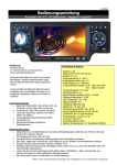
Bedienungsanleitung
Funk-Alarmanlagenset “FAS-4000”
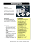
Einführung
Geehrter Kunde,
wir möchten Ihnen zum Erwerb Ihrer
neuen Alarmanlage gratulieren!
Mit dieser Wahl haben Sie sich für ein
Produkt entschieden, welches ansprechendes
Design und durchdachte technische Features
gekonnt vereint.
Lesen Sie bitte die folgenden Bedienhinweise
sorgfältig durch und befolgen Sie diese, um in
möglichst ungetrübten Genuss des Gerätes zu
kommen!
Leistungsmerkmale
Mit diesem Alarmanlagenset ist eine Objektsicherung
einfach zu bewerkstelligen. Steuerbar mit den zwei
Funkfernbedienungen sorgt die Anlage mit ihrem
Bewegungsmelder, den Fenster- bzw Türkontakten
sowie ihrem Panikschalter für eine hohe Sicherheit in
Heim, Büro oder Ladengeschäft.
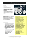
Sicherheitshinweise
•
•
•
•
•
•
•
Überprüfen Sie vor Inbetriebnahme das Gerät
auf Beschädigungen, sollte dies der Fall sein,
bitte das Gerät nicht in Betrieb nehmen!
Lassen Sie Gerät nicht fallen. Es könnte bein
Aufprall auf haretem Untergrund beschädigt
werden.
Testen Sie die Funktion der Anlage nach ihrer
Installation.
Vermeiden Sie die Installation an Orten mit
starken Temperaturdifferenzen oder hoher
Feuchtigkeit.
Wichtig! Sollten das Gerät einmal beschädigt
werden, lassen Sie es nur durch den Hersteller
oder eine Fachwerkstatt instandsetzen.
Lassen Sie das Verpackungsmaterial nicht
achtlos liegen, Plastikfolien / -tüten,
Styroporteile, etc., könnten für Kinder zu einem
gefährlichen Spielzeug werden.
Das Gerät gehört nicht in Kinderhände. Es ist
kein Spielzeug.
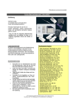
Technische Daten:
Maße LxBxT: 240x130x50 mm (Haupteinheit)
Maße LxBxT: 75x80x60 mm (Sirene)
Maße LxBxT: 85x45x20 mm (Fernbedienung)
Maße LxBxT: 115x90x60 mm (Bewegungsmelder)
Maße LxBxT: 105x45x20 mm (Fensterkontakt)
Betrieb Haupteinheit: AC 230V ~ 50 Hz
Betrieb Bewegungsmelder: 9 V (6F22) Blockbatterie
Betrieb Fernbedienung: 3 V (CR2025) Batterie
Betrieb Türkontakt: 12 V (A23) Batterie
Nennstrom Haupteinheit: 150 mA
Nennstrom Sirene: max. 800 mA
Nennstrom Bewegungsmelder: 30 µA
Sensorreichweite Bewegungsmelder: 12 m
Sensorwinkel Bewegungsmelder: 110°
Installationshöhe Bewegungsmelder: 2 m
Reichweite Fernbedienung: max 30 m
Piezosirene: 108 dB / Dauer: 300 s
Austrittsverzögerung: 60 Sekunden
Eintrittsverzögerung: 15 Sekunden
Fenster-/Türkontakte: 2
Arbeitsfrequenz: 433 MHz
Systempasswort: 000000
Benutzerpasswort: 1234
P2008 © Firma WJG, Braunschweig. Nachdruck oder Vervielfältigung nur mit ausdrücklicher Genehmigung
530-333
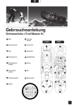
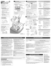
Die Haupteinheit und ihre Funktionen:
1
2ABC
3DEF
AWAY
4GHI
5JKL
6MNO
HOME
7 PQRS
8TUV
9WXYZ
SET
0
#
ARM
POWER
A
B
MEDICAL FIRE
C
HELP
Die Fernbedienung und der Notfallsender und ihre Funktionen:
push up
disarm
home arm
help alarm
Z
help alarm
away arm
Betrieb der Alarmanlage:
Nach erfolgter Installation und Programmierung kann man die Alarmanlage mit Hilfe der Haupteinheit, der
Fernbedienungen sowie des Notfallsenders nutzen und bedienen.
Folgende Funktionen sind evident.
•
•
•
•
Die Alarmanlage scharf stellen: Drücken Sie auf AWAY ARM der Fernbedienung oder AWAY der
Haupteinheit, um die Anlage zu aktivieren. Auf dem Display erscheint [ARM ST] und die Haupteinheit
quittiert mit einem akustischen Signal. Nun hat man die Dauer der unter 1.4. eingestellten
Austrittsverzögerung zur Verfügung, um den überwachten Bereich zu verlassen, ohne Alarm auszulösen.
Die Alarmanlage entschärfen: Drücken Sie auf DISARM der Fernbedienung oder geben Sie das
Bedienerpasswort an der Haupteinheit ein, um die Anlage zu deaktivieren. Auf dem Display erscheint
[DISARM ST] und die Haupteinheit quittiert mit einem akustischen Signal. Im zweiten Fall beachten Sie,
dass Sie nur die Dauer der unter 2.2. eingstellten Eintrittsverzögerung zur Verfügung haben, um das
Passwort einzugeben, ohne Alarm auszulösen.
Nur die Peripheriealarmschleifen aktivieren: Drücken Sie auf HOME ARM der Fernbedienung oder HOME
der Haupteinheit, um die Alarmanlage ohne den Bewegungsmelder zu aktivieren. Auf dem Display
erscheint [GUARD ST] und die Haupteinheit quittiert mit einem akustischen Signal. Nach Ablauf der
unter 1.4. eingestellten Austrittszeit wird Alarm ausgelöst, wenn einen Tür- oder Fensterkontakt öffnet.
Ansonsten können Sie sich innerhalb des überwachten Bereiches frei bewegen.
Panikalarm aktivieren: Drücken Sie auf HELP ALARM der Fernbedienung oder des Notfallsenders oder
auf entweder MEDICAL, FIRE oder HELP der Haupteinheit, um einen sofort einsetzenden Alarm
auszulösen und die Haupteinheit die Alarmzentrale anrufen zu lassen. Es wird entweder die Nachricht
„medical alarm“, „fire alarm“ oder „help alarm“ übermittelt.
P2008 © Firma WJG, Braunschweig. Nachdruck oder Vervielfältigung nur mit ausdrücklicher Genehmigung
530-333
•
•
•
Alarm abschalten: Ein laufender Alarm kann durch die Eingabe des Bedienerpasswortes manuell beendet
werden. Ansonsten wird er nach Ablauf der unter 3.1. eingegebenen Zeitspanne automatisch
abgeschaltet.
Alarmmeldung per Telefon erhalten: Die Alarmanlage wählt die von Ihnen einprogrammierte Nummer
einer Alarmzentrale und ggf. auch bis zu drei Alternativnummerm an und gibt einer der vier möglichen
Alarmmeldungen ab {<security alarm>, <fire alarm>, <gas alarm> oder <help alarm>}, je nachdem,
wie der Alarm ausgeöst wurde. Dabei ist es wichtig, der Alarmanlage durch das Drücken der #-Taste
Ihres Telefons mitzuteilen, dass der Anruf angekommen ist. Ansonsten wählt die Anlage die
programmierten Telefonnummern immer wieder an.
Fernbedienung der Alarmanlage über das Telefon: Wählen Sie den Anschluss unter der die Anlage am
Telefonnetz angeschlossen ist und warten die programmierte Anzahl der Klingeltöne ab. Aus
Sicherheitsgründen wird der angerufene Anschluss nicht laut klingeln. Geben Sie danach das
Bedienerpasswort ein und bestätigen die Eingabe mit #. Jetzt können Sie mit den Numeriktasten ihres
Telefons folgende Funktionen steuern: [1] = Scharfschalten, [2] = Entschärfen, [3] = Monitorfunktion
aktivieren, d.h. das in die Haupteinheit integrierte Mikrofon wird aktiviert und Sie können in den Raum
hineinhören, [4] = Die Alarmanlage sieht den Anruf als beendet an.
Installation der Alarmanlage:
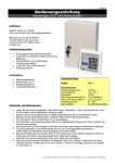
a) Die Haupteinheit
160
78
out-line hole
•
•
•
•
•
•
•
•
Lösen sie die Schrauben auf der Vorderseite der Haupteinheit.
Benutzen Sie die Löcher der Rückseite als Schablone für die drei Bohrpunkte.
Bohren Sie die drei Löcher, deren Abstände zueinander der obigen Zeichnung zu entnehmen sind.
Setzen Sie die Dübel ein.
Drehen Sie die Schrauben bis ca. 5 mm in die Wand.
Entfernen Sie die Kappen der Löcher für die Leitungen und schließen Sie das Netzteil und ggf. die
Telefonleitung an.
Befestigen Sie die Rückseite an der Wand.
Setzen Sie das Fronteil wieder auf und schrauben es fest.
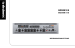
b) Die zweiteiligen Magnetkontakte für Tür und Fenster
D oor
D o o r fra m e
D o o r lo c k
C o rre ct p ositio n
Incorre ct p osition
P2008 © Firma WJG, Braunschweig. Nachdruck oder Vervielfältigung nur mit ausdrücklicher Genehmigung
530-333
•
•
•
•
Die beiden Teile der Kontake müssen jeweils senkrecht an der Anschlagseite von Tür und Türrahmen
oder Fenster und Fensterrahmen befestigt werden, wobei das größere Teil (Sender) immer an den
Rahmen gehört.
Der Magnet muß immer zur linken Seite des Senders angebracht werden.
Ihr Abstand voneinander darf im geschlossenen Zustand nicht mehr als 5 mm betragen.
Achtung: Die Kontakte sollten nicht auf metallenden Untergrund angebracht werden.
c) Der Bewegungsmelder
•
•
•
•
•
•
•
Setzen sie den Bewegungsmelder in ca. 2 m Höhe an die Wand an.
Benutzen Sie die Löcher seines Halters als Schablone für die
Bohrpunkte.
Bohren Sie die Löcher.
Setzen Sie die Dübel ein.
Schrauben Sie den Halter an der Wand fest.
Nun befestigen Sie den Bewegungsmelder an seinem Halter.
Achtung: Der Bewegungsmelder sollten nicht auf metallenden
Untergrund angebracht werden.
Der Sensorbereich des Bewegungsmelders:
¾
Achtung: Sollte die Betriebsspannung der Batterie unter 7 V fallen, zeigt die rote Leuchtiode des
Bewegungsmelders an.
P2008 © Firma WJG, Braunschweig. Nachdruck oder Vervielfältigung nur mit ausdrücklicher Genehmigung
530-333
Programmierung:
Um Einstellungen am System vorzunehmen benötigt man das Systempasswort, welches vom Werk her
<000000> ,lautet. Das Benutzerpasswort zum Abschalten der Alarmanlage lautet ab Werk <1234>.
Achtung: Das Systempasswort ist die höchste Instanz. Nur mit ihm kann man das Benutzerpasswort ändern oder
Einstellungen an der Haupteinheit vornehmen. Deshalb darf das Systempasswort selbst erst dann geändert
werden, wenn die Anlage komplett angeschlossen und konfiguriert ist.
Nachdem die Anlage erfolgreich angschlossen ist und angeschaltet wurde sollten die Leuchtdioden POWER
(grün) und ARM (rot) anzeigen.
Auf dem Display wird nun entweder [ARM ST] oder [GUARD ST] angezeigt, was bedeutet, dass die Alarmanlage
scharfgeschaltet ist. Schalten Sie den Alarmzustand mit dem Benutzerpasswort ab.
Wenn auf dem Display [DISARM ST] angezeigt wird, war die Eingabe erfolgreich und man kann die Anlage
programmieren.
Disarm St
Um das Einstellungsmenü aufzurufen, drückt man SET.
Auf dem Display erscheint die Eingabeaufforderung [INPUT LEVEL]. Hier muß das Systempasswort eingegeben
und die Eingabe mit # bestätigt werden.
War die Eingabe erfolgreich erscheinen auf dem Display die Menüpunkte [1. SYS, 2. ZONE, 3. SETUP, 4.
STUDY].
Input level
******
1.Sys
2.Zone
3.Setup 4.Study
Das Funktionsmenü:
Um sich in dem Funktionsmenü zu bewegen oder Eingaben zu bestätigen drückt man eine der zur Auswahl
gestellten Zifferntasten.
Um zum vorherigen Menüpunkt zurückzukehren muß man * drücken.
Um eine Eingabe abzuschließen und zu bestätigen muß man # drücken.
Die Schaltungen des Funktionsmenüs sehen im Überblick folgendermaßen aus:
P2008 © Firma WJG, Braunschweig. Nachdruck oder Vervielfältigung nur mit ausdrücklicher Genehmigung
530-333
Arm state
1.Sys level
2.User level
1.Level
2.Code
3.Report
4.Delay
1.Sys
1.Arm report
2.No report
01
02
03
04
05
…
12
2. Zone
Disarm state
Wired
1. Instant
2. Delay (zone)
3. 24 HR
4.Bypass
1.Smoke
2.Gas
3.Panic
Wireless
3. Setup
1. Alert
2. Home
3. Call
4. Del home
1.Tel
2.Dial
3.Vibrant ring
1. Tele 1
2. Tele 2
3. Tele 3
4. Tele 4
1.Remote
2.Arm zone
3.Del
4. Study
Guard state
Die Menüpunkte im einzelnen:
Um in das Einstellungsmenü zu gelangen, drücken Sie SET. Daraufhin erscheint auf dem Display [INPUT LEVEL].
Geben Sie nun das Systempasswort ein und bestätigen die Eingabe mit #.
Nach erfolgreicher Codeeingabe erscheint auf dem Diplay die Auwahl [1. SYS, 2. ZONE, 3. REPORT, 4. STUDY].
1.Sys
2.Zone
Press
1.level
3.Setup 4.Study
2. code
3.report 4.delay
1. SYS (Systemeinstellungen)
1.1. LEVEL (Änderung von Passwörtern)
1.1.1. SYS LEVEL (Änderung des Systempasswortes)
Auf dem Display wird [INPUT SYS LEVEL] angezeigt.
Hier gibt man ein neues sechstelliges Passwort ein und bestätigt mit #.
Achtung: Die Anlage speichert nur das zuletzt eingegebene Passwort. Da es keinen Mastercode gibt, muß man
sich das Systempasswort immer gut merken, da man ansonsten keine Einstellungen an der Kontrolleinheit
vornehmen kann!
Input sys level
******
P2008 © Firma WJG, Braunschweig. Nachdruck oder Vervielfältigung nur mit ausdrücklicher Genehmigung
530-333
1.1.2. USER LEVEL (Änderung des Benutzerpasswortes)
Auf dem Display wird [INPUT USER LEVEL] angezeigt.
Hier gibt man ein neues vierstelliges Passwort ein und bestätigt mit #.
Achtung: Die Anlage speichert nur das zuletzt eigegebene Passwort, deshalb sollte man es sich gut merken.
Input user level
****
1.2. CODE
1.3. REPORT (Erstellung eines Alarmreports)
1.3.1. ARM REPORT
Bei der Wahl dieses Punktes, wird im Fall eines Alarms ein Alarm-Report erstellt, der dann telefonisch an eine
Alarmzentrale gesendet wird. Auf dem Display erscheint [1. ARM REPORT].
1.3.2. NO REPORT
Ist die Anlage an keiner Alarmzentrale angeschlossen kann man hiermit die Alarmreportfunktion deaktivieren. Es
wird kein Alarmreport erstellt. Auf dem Display erscheint [2. NO REPORT].
.
:
1. Arm report
2. No report
1.4. DELAY (Einstellung der Austrittsverzögerung)
Auf dem Display erscheint [INPUT DELAY]. Hier gibt man einen Wert zwischen 0 und 99 Sekunden ein und
bestätigt ihn mit #. Dies ist die Verzögerungszeit, die vom Scharfstellen der Alarmanlage bis zur Aktivierung
verstreicht, damit man Zeit hat ihren Sensorbereich zu verlassen.
Input delay
**
2. ZONE (Einstellung der Alarmschleifen)
Auf dem Display erscheint [INPUT ARM ZONE:]. Hier geben sie die Nummer der Alarmschleifen von 01 bis 12
ein, die konfigurieren möchten und bestätigen mit #. Im nächsten Schritt können Sie dann auswählen, welche
Funktion die einzelnen Schleifen haben sollen. Es ist dabei zu beachten, dass die Schleifen 01 bis 04
leitungsgebunden sind, während die Schleifen 05 bis 12 Funkübertragung nutzen.
Input arm zone:
**
Nachdem, die zu konfigurierende Alarmschleife ausgewählt und mit # bestätigt worden ist erscheint auf dem
Display die Auswahl [1. INSTANT, 2. DELAY, 3. 24HRS, 4 BYPASS].
1.instant
2.delay
3.24Hr
4.bypass
2.1. INSTANT (Sofortalarm)
In diesem Zustand löst die Alarmanlage sofortigen Alarm aus, sobald der Sensor dieser Schleife etwas
wahrnimmt. Im Alarmfall erscheint auf dem Display [SECURITY ALARM].
P2008 © Firma WJG, Braunschweig. Nachdruck oder Vervielfältigung nur mit ausdrücklicher Genehmigung
530-333
2.2. DELAY (Einstellung der Eintrittsverzögerung)
Auf dem Display erscheint [INPUT DELAY]. Hier gibt man einen Wert zwischen 0 und 99 Sekunden ein und
bestätigt ihn mit #. Dies ist die Verzögerungszeit, die vom Betreten des Sensorbereiches bis zum Auslösen eines
Alarms verstreicht, damit man Zeit hat die Alarmanlage zu deaktivieren. Im Alarmfall erscheint auf dem Display
[SECURITY ALARM] .
Input delay
**
2.3. 24 HR (Einstellung einer permanent aktiven Alarmschleife)
An diese werden in der Regel Sensoren wie Gas- oder Feuermelder angeschlossen, allerdings ist auch die
Schaltung eines Panikalarms, zum Herbeirufen von Hilfe, sehr sinnvoll. Auf dem Display erscheint das
Auswahlmenü [1. SMOKE, 2. GAS, 3. PANIC].
1.Smoke
2.Gas
3. Panic
2.3.1. SMOKE (Rauch- oder Feueralarm)
Diesen Punkt wählen Sie, wenn an diese Schleife ein Rauch- oder Feuermelder angeschlossen ist. Bestätigen Sie
die Eingabe mit #. Im Alarmfall erscheint auf dem Display [FIRE ALARM].
2.3.2. GAS (Gasalarm)
Diesen Punkt wählen Sie, wenn an diese Schleife ein Gasmelder angeschlossen ist. Bestätigen Sie die Eingabe
mit #. Im Alarmfall erscheint auf dem Display [GAS ALARM].
2.3.3. PANIC (Panikalarm)
Diesen Punkt wählen Sie, wenn an diese Schleife der Panikalarm angeschlossen ist. Er kann durch den HELPKnopf an der Haupteinheit oder an der Fernbedienung ausgelöst werden. Bestätigen Sie die Eingabe mit #. Im
Alarmfall erscheint auf dem Display [HELP ALARM].
2.4. BYPASS ( Deaktivierung einer Alarmschleife)
Durch Auswahl dieser Option wird die ausgewählte Alarmschleife komplett deaktiviert.
3. SETUP ( Allgemeine Einstellungen)
Auf dem Display erscheint die Auswahl [1. ALERT, 2. HOME, 3. CALL, 4. DEL. HOME].
1.alert
2.home
3.call
4.del home
3.1. ALERT (Dauer eines Alarms)
Auf dem Display erscheint [SET ALARM TIME]. Hier geben sie die Dauer des Alarms ein, in der die Sirene ertönt
von 0 bis 999 Sekunden ein und bestätigen mir #. Die Werkseinstellung beträgt 300 Sekunden.
Set alarm time
***
P2008 © Firma WJG, Braunschweig. Nachdruck oder Vervielfältigung nur mit ausdrücklicher Genehmigung
530-333
3.2. HOME (Nur die Peripheriealarmscheifen aktivieren):
Falls man sich innerhalb des Bereiches der Alarmanlage frei bewegen möchte, ohne den Alarm auszulösen und
trotzdem abgesichert sein möchte, benutzt man die HOME-Taste der Haupteinheit oder der Fernbedienung. Bei
dieser Schaltung sind alle Alarmkontakte an Fenster und Türen weiter aktiv, nur der Bewegungsmelder ist
ausgeschaltet. Auf dem Display erscheint [SET ARM ZONE NO.]. Hier gibt man die Nummer der Alarmschleife
ein, an die der Bewegungsmelder angeschlossen ist und bestätigt mit #.
Set arm zone NO.
**
3.3. CALL (Einstellung der Telefonverbindung)
Auf dem Display erscheint die Auswahl [1. TEL, 2. DIAL, 3. VIBRANT RING].
3.3.1. TEL (Eingabe von Telefonnumern für die Alarmmeldung)
Auf dem Display erscheint die Anzeige zur Eingabe der Telefonnummern.
1.tel
2.tel
3.tel
4.tel
3.3.1.1. TEL 1 (Nummer der Alarmzentrale)
Geben Sie hier die Nummer ein, die im Alarmfall von der Alarmanlage angerufen werden soll. Sie kann zwischen
3 und 13 Stellen haben.
3.3.1.2. TEL 2 (Alternativnummer)
Wenn der Anruf an TEL 1 nicht nach der angegebenen Anzahl von Wahlwiederholungen angenommen wird,
wählt die Alarmanlage die Nummer von TEL 2. Hier können Sie die Nummer von TEL 2 eingeben. Sie kann
zwischen 3 und 13 Stellen haben.
3.3.1.3. TEL 3 (Alternativnummer)
Wenn der Anruf an TEL 2 nicht nach der angegebenen Anzahl von Wahlwiederholungen angenommen wird,
wählt die Alarmanlage die Nummer von TEL 3. Hier können Sie die Nummer von TEL 3 eingeben. Sie kann
zwischen 3 und 13 Stellen haben.
3.3.1.4. TEL 4 (Alternativnummer)
Wenn der Anruf an TEL 3 nicht nach der angegebenen Anzahl von Wahlwiederholungen angenommen wird,
wählt die Alarmanlage die Nummer von TEL 4. Hier können Sie die Nummer von TEL 4 eingeben. Sie kann
zwischen 3 und 13 Stellen haben.
3.3.2. DIAL (Anzahl der Wahlwiederholungen)
Wenn eine Telefonnummer belegt ist, wird die Anwahl so oft wiederholt, wie hier festgelegt. Die
Werkseinstellung beträgt 3 mal. Ist die angerufene Nummer danach immer noch belegt, dann wird die nächste
angerufen, bis der Anruf angenommen und mit # bestätigt wird. Auf dem Display erscheint [SET DIAL TIMES].
Nachdem man die gewünschte Anzahl der Wahlwiederholungen eingegeben hat bestätigt man mit #.
Set dial times
**
P2008 © Firma WJG, Braunschweig. Nachdruck oder Vervielfältigung nur mit ausdrücklicher Genehmigung
530-333
3.3.3. VIBRANT RING (Anzahl der stillen Klingeltöne festlegen)
Man kann die Alarmanlage von außen anrufen und auch einstellen. Dabei wird aus Sicherheitsgründen kein
lautes Klingelzeichen produziert, sondern nur ein Vibrationsalarm. Die Anzahl dieser Töne bis die Alarmanlage
abnimmt kann hier festgelgt werden. Auf dem Display erscheint [INPUT RING TIMES]. Geben Sie die
gewünschte Anzahl von 1 bis 99 mal ein. Die Werkseinstellung ist 8 mal.
Input ring times
**
3.3.4. DEL HOME (Löschen der Einstellungen für den HOME Modus)
Hier werden alle Einstellungen zum HOME-Modus gelöscht, d.h. man muß diese im Bedarfsfall neu
programmieren.
4. STUDY (Einstellung der Magnetkontakte und der Fernbedienungen)
Damit die Sensoren und die Fernbedienungen auf separaten Frequenzen mit der Haupteinheit kommunizieren
und auch fehlerfrei erkannt werden können, müssen sie korrekt eingestellt werden.
Dies geschieht bei den Tür-/Fensterkontakten durch DIP-Schalter, die sich in den Batteriefächern befinden.
.
An jedem der beteiligten Tür-/Fensterkontakten muß eine individuelle ON/OFF-Kombination der 8 Schalter
eingestellt werden. Am einfachsten wäre also z.B. Tür-/Fensterkontakten 1: 1 = ON & 2 bis 8 = OFF; Tür/Fensterkontakten 2: 2 = ON & Rest = OFF usw.
Jede DIP-Kombination entspricht einem Funkkanal.
Stellen Sie sicher, dass keine DIP-Schalterkombination doppelt vorkommt.
Der Bewegungsmelder findet seinen Funkkanal automatisch, in dem man CODING SWITCH drückt.
Wenn Jumper 2 (JP2) gesetzt ist, blinkt die grüne Leuchtiode, wenn der richtige Funkkanal gefunden wurde.
Nun kann man CODING SWITCH loslassen und die grüne Leuchtdiode zeigt an, dass der Funkkontakt zur
Haupteinheit steht.
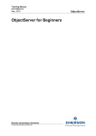
Beim Bewegungsmelder läßt sich zusätzlich mit einem Jumper 1 (JP1) festlegen, ob das Signal zur Alarmanlage
schon beim ersten Erkennen einer Bewegung gesendet wird (Sense one to emit) oder erst dann, wenn eine
zweite Bewegung in einem bestimmten Abstand folgt (Sense twice to emit). Den Zeitabstand kann man mit dem
ADJUSTER zwischen 0 und 2 Minuten einstellen. Diese zweite Möglichkeit soll die Wahrscheinlichkeit von
Fehlalarmen minimieren.
2min
coding switch
JP1
1
sense twice to emit
1
sense once to emit
JP2
1
LED ON/OFF
JP1
sense LED(green)
emit LED(red)
0sec
I AUTO
adjuster
JP2
LED OFF
PIR
adjuster adjust emission time interval
LED ON
clockwise to the end is 2min~2.5min
anti-clockwise to the end is 0sec
Der Notfallsender (MEDICAL) hat einen fest vorprogramierten Kanal, während die Fernbedienungen ihren Kanal
automatisch finden, wenn sie „angelernt“ werden.
P2008 © Firma WJG, Braunschweig. Nachdruck oder Vervielfältigung nur mit ausdrücklicher Genehmigung
530-333
Nun folgt das sogenannte Anlernen, d.h. es können bis zu vier Fernbedienungen, welche den Alarmschleifen 1
bis 4 zugeordnet sind, und bis zu acht Sensoren, die den Alarmschleifen 5 bis 12 zugeordnet werden, mit der
Haupteinheit koppeln.
1.remote
2.arm zone
3. del
4.1. REMOTE (Fernbedienungen anlernen)
Als Vorbereitung schrauben Sie die Fenbedienung auf und halten eine ihrer Testen (S1 –S4) gedrückt, während
Sie die Batterie einsetzen. Nun sollte die Leuchtdiode blinken. Schrauben Sie die Fernbedienung wieder
zusammen.
Geben sie an der Haupteinheit die Nummer des gewünschten Speicherplatzes von 1 bis 4 ein und bestätigen die
Eingabe mit #. Nun drücken Sie eine beliebige Taste der Fernbedienung, die damit korrespondieren soll. Wenn
ein Piepton ertönt, war der Zuordnungsprozess erfolgreich.
Dieser Vorgang muß für jede beteiligte Fernbedienung individuell durchgeführt werden.
4.2. ARM ZONE (Magnetkontakte anlernen)
Geben sie an der Haupteinheit die Nummer des gewünschten Speicherplatzes von 5 bis 12 ein und bestätigen
die Eingabe mit #. Nun lösen Sie den Sensor einmal aus, also durch Öffnen und Schließen des Magnetkontaktes.
Wenn ein Piepton ertönt, war der Zuordnungsprozess erfolgreich.
Dieser Vorgang muß für jeden beteiligte Sensor individuell durchgeführt werden.
4.3. DEL ( Löschung aller gespeicherten Geräte)
Durch Aufrufen dieser Funktion werden alle gespeicherten Zuordnungen zu den Fernbedienungen und den
Sensoren komplett gelöscht.
Der Funktionstest der Alarmanlage (Walk-Test):
•
•
•
•
•
•
•
•
Nach der Installation der Alarmanlage, betätigen Sie den AWAY ARM-Knopf der Fernbedienung.
Jetzt ist die Alarmanlage inklusive des Bewegungsmelders aktiviert.
Bewegen Sie sich jetzt innerhalb des Bereiches der Bewegungsmelders.
Der Bewegungsmelder wird Ihre Anwesenheit registrieren und sendet der Haupteinheit ein Signal.
Nach Ablauf der Eintrittsverzögerung beginnen sowohl die integrierte Sirene der Haupteinheit als auch
die externe Piezosirene Alarm zu schlagen.
Sie können den Alarm vorzeitig durch Eingabe des Bedienerpasswortes abbrechen.
Betätigen Sie nun die HOME ARM-Taste der Fernbedienung. Jetzt sind nur die Alarmschleifen mit den
Magnetkontakten aktiv.
Wenn Sie jetzt eines der gesicherten Fenster öffnen, beginnen sowohl die Sirene der Haupteinheit als
auch die externe Piezosirene Alarm zu schlagen.
Grundsätzlich sollte man nicht direkt von der HOME ARM-Funktion zur AWAY ARM-Funktion,oder umgekehrt,
schalten. Dies kann zu Störungen in der Alarmanlage führen, d.h. vor dem Umschalten immer die DISARM-Taste
betätigen.
P2008 © Firma WJG, Braunschweig. Nachdruck oder Vervielfältigung nur mit ausdrücklicher Genehmigung
530-333
Reference Manual
RC-controlled Alarm-System „FAS-4000“
Preface
Dear Customer,
we like to congratulate you on the
purchase of your new alarm-system!
You have chosen a product which
combines deliberate technical features
with an appealing design.
Please read this manual conscientiously
and carry out the given instructions before
and while you are using your new device.
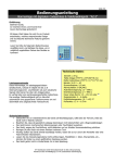
Technical Specifications:
Capability Characteristics
With this alarm-system-set you manage to keep any
room safe easily.
Operate the system by using the two radio remote
controls. The device will provide a high degree of
security with its motion sensor, the magnetic contacts
and the panic-button. Ideal for home, office or shop.
Security Advices
•
•
•
•
•
•
•
Before using the device, please check it for
any possible damages. In case of damage do
not operate it.
Dropping on hard floor may cause a damage
on the device.
Do not forget to test the function of the device
after installation.
Do not install the main device at places with
strong fluctuation of temperature or humidity.
Caution! Should the device itself get damaged,
please let the repair to the manufacturer or to
a qualified service agent.
Please dispose packaging materials properly
and do not let play children with it.
The device itself is no toy either. Do not let
children play with it too.
Size LxBxT: 240x130x50 mm (main unit)
Size LxBxT: 75x80x60 mm (hooter)
Size LxBxT: 85x45x20 mm (remote control)
Size LxBxT: 115x90x60 mm (motion detector)
Size LxBxT: 105x45x20 mm (magnetic contact)
Operation Main Unit: AC 230V ~ 50 Hz
Operation Motion Detector: 9 V (6F22) battery
Operation Remote Control: 3 V (CR2025) battery
Operation Magnetic Contact: 12 V (A23) battery
Rated Current Main Unit: 150 mA
Rated Current Hooter: max. 800 mA
Rated Current Motion Detector: 30 µA
Sensor Range Motion Detector: 12 m
Sensor Angle Motion Detector: 110°
Installation Height Motion Detector: 2 m
Range Remote Control: max 30 m
Piezo-Siren: 108 dB / Dauer: 300 s
Exit Delay: 60 s
Entry Delay: 15 s
Number of Magnetic Contacts: 2
Working Frequency: 433 MHz
System Password: 000000
User Password: 1234
P2008 © Firma WJG, Braunschweig. Nachdruck oder Vervielfältigung nur mit ausdrücklicher Genehmigung
530-333
The Main Unit and its Functions:
1
2ABC
3DEF
AWAY
4GHI
5JKL
6MNO
HOME
7 PQRS
8TUV
9WXYZ
SET
0
#
ARM
POWER
A
B
MEDICAL FIRE
C
HELP
The Remote Control and the Help Alarm Emitter and their Functions:
push up
disarm
home arm
help alarm
Z
help alarm
away arm
Operation of the Alarm System:
After the installation and the programming of the system it can be operated by the main unit, the remote
controls and the help alarm emitter.
Following functions are evident.
•
•
•
•
Arming of the alarm system: Press AWAY ARM of the remote control or AWAY of the main unit to
activate the system. The display shows [ARM ST] and the main unit acknowledges with an acoustic
signal. During the under 1.4. adjusted exit delay it is possible to leave the monitored area without
raising an alarm.
Disarming of the alarm system: Press DISARM of the remote control or enter the user password at the
main unit to deactivate the system. The display shows [DISARM ST] and the main unit acknowledges
with an acoustic signal. In the second case make sure to enter the password during the time of the
under 2.2. adjusted entry delay. Otherwise the alarm is rising.
Activating only the periphery alarm strip: Press HOME ARM of the remote control or HOME of the main
unit to activate the alarm system without the motion detector. The display shows [GUARD ST] and the
main unit acknowledges with an acoustic signal. After the expiration of the under 1.4. adjusted exit
delay the alarm raised if a magnetic contact on door- or window opens. But in this mode it is possible to
move freely inside the monitored area.
Activating the help alarm: Press HELP ALARM of the remote control or the help alarm emitter or either
MEDICAL, FIRE or HELP of the main unit to raise an alarm instantly. Furthermore the main unit will dial
the number of the guarding station. It will either leave message „medical alarm“, „fire alarm“ or „help
alarm“.
P2008 © Firma WJG, Braunschweig. Nachdruck oder Vervielfältigung nur mit ausdrücklicher Genehmigung
530-333
•
•
•
Stopping the alarm: Stop a running alarm manually by entering the user password. Otherwise the alarm
quits automatically after the under 3.1. adjusted period of time.
Getting an alarm report via telephone: The alarm system is calling the programmed number and as the
case may be up to three alternative numbers to leave one of these messages {<security alarm>, <fire
alarm>, <gas alarm> or <help alarm>} depending on the reason for the alarm. It is important that the
callee is pressing the #-key of his telephone to inform the alarm system that its message reached
somebody. Otherwise the alarm system keeps calling the programmed numbers.
Remote controlling of the alarm system via telephone: Call the number of the line to which the alarm
system is connected and wait until the programmed number of rings is done. For safety reasons the
called telephone will not ring loudly. After the alarm system picked up enter the user password and
confirm the input with #. Now use the numerical keys of your phone to operate the following functions:
[1] = Arming, [2] = Disarming, [3] = Activating the monitor function which means you can listen into
the room with the integrated microphone, [4] = The alarm system cuts the line.
Installation of the Alarm System:
a) The main unit
160
78
out-line hole
•
•
•
•
•
•
•
•
Release the screws of the front panel of the main unit.
Use the holes of the backside as a positioning device for the three drill holes.
Drill the three holes which distances to each other can be read from the drawing above.
Insert the wall plugs into the holes.
Insert the screws into the wall but leave about 5 mm standing out.
Remove the covers of the holes for the wires and connect the power supply and as the case may be the
telephone line.
Mount the backside to the wall.
Put the front panel on the backside and tighten its screws.
b) The two-part magnetic contacts for windows and doors
D oor
D o o r fra m e
D o o r lo c k
C o rre ct p ositio n
Incorre ct p osition
P2008 © Firma WJG, Braunschweig. Nachdruck oder Vervielfältigung nur mit ausdrücklicher Genehmigung
530-333
•
•
•
•
The two pieces of each contact must be fastened perpendicularly at the attaching point of door and its
frame or window and its frame. Make sure to mount the bigger part (emitter) to the frame.
The magnet must be installed to the left side of the emitter.
If the window or door is closed the distance of the two pieces from each other should not be more than
5 mm.
Attention: Do not install the magnetic contact on a metal surface.
c) The motion detector
•
•
•
•
•
•
•
Hold the motion detector to the wall in about 2 m of height.
Use the holes of the holder as a positioning device for the two drill
holes.
Drill the holes.
Insert the wall plugs.
Mount the holder to the wall.
Now fasten the motion detector to its holder.
Attention: Do not install the motion detector on a metal surface.
The sensor range of the motion detector:
¾
Attention: Should the operating voltages fall under 7 V the red LED of the motion detector will show.
P2008 © Firma WJG, Braunschweig. Nachdruck oder Vervielfältigung nur mit ausdrücklicher Genehmigung
530-333
Programming:
For adjusting the system the system password is needed. Its factory setting is <000000>. The user password to
switch off the alarm system is <1234> by factory setting.
Attention: The system password is the highest entity. Only with this it is possible to change the user password
or make adjustments at the main unit. For safety reasons change the system password itself not before the
whole system is installed and configured successfully.
After the system was installed successfully and switched on the LEDs POWER (green) and ARM (red) shows.
The display shows either [ARM ST] or [GUARD ST] which means the system is armed. So disarm the system by
entering the user password.
If the display shows [DISARM ST] the input was made successfully and the main unit is ready to adjust the
alarm system.
Disarm St
For calling the adjustment menu press SET.
The display shows [INPUT LEVEL]. Here the input of the system password is necessary. Confirm the input with
#.
If the password was entered correctly the display shows the choices [1. SYS, 2. ZONE, 3. SETUP, 4. STUDY].
Input level
******
1.Sys
2.Zone
3.Setup 4.Study
The Function Menu:
For moving inside the function menu or to confirm an input press the numerical key of your choice.
For returning to the previous level press *.
For finishing and for confirmation of an input use #.
The coupling of the function menu at a glance:
P2008 © Firma WJG, Braunschweig. Nachdruck oder Vervielfältigung nur mit ausdrücklicher Genehmigung
530-333
1.Sys level
2.User level
Arm state
1.Level
2.Code
3.Report
4.Delay
1.Sys
1.Arm report
2.No report
01
02
03
04
05
…
12
2. Zone
Disarm state
Wired
1. Instant
2. Delay (zone)
3. 24 HR
4.Bypass
1.Smoke
2.Gas
3.Panic
Wireless
3. Setup
1. Alert
2. Home
3. Call
4. Del home
1.Tel
2.Dial
3.Vibrant ring
1. Tele 1
2. Tele 2
3. Tele 3
4. Tele 4
1.Remote
2.Arm zone
3.Del
4. Study
Guard state
The menu’s items one by one:
For entering the adjustment menu press SET. Now the display shows [INPUT LEVEL]. Enter the system
password and confirm it with #.
After the input of the correct password the display shows [1. SYS, 2. ZONE, 3. REPORT, 4. STUDY].
1.Sys
2.Zone
Press
1.level
3.Setup 4.Study
2. code
3.report 4.delay
1. SYS (System Setting)
1.1. LEVEL (Changing Passwords)
1.1.1. SYS LEVEL (Change the System Password)
The display shows [INPUT SYS LEVEL].
Here enter a new six digit password and confirm it with #.
Attention: The alarm system recognizes only the last saved password. Because there is no mastercode it is
evident not to forget the system password. Without this it is impossible to make adjustment at the main unit.
Input sys level
******
P2008 © Firma WJG, Braunschweig. Nachdruck oder Vervielfältigung nur mit ausdrücklicher Genehmigung
530-333
1.1.2. USER LEVEL (Change the User Password)
The display shows [INPUT USER LEVEL].
Here enter a new four digit password and confirm with #.
Attention: The alarm system recognizes only the last saved password.
Input user level
****
1.2. CODE
1.3. REPORT (Alarm Report Setting)
1.3.1. ARM REPORT
Choosing this item means that in case of alarm an alarm report will be created and send to a monitoring station
via telephone. The display shows [1. ARM REPORT].
1.3.2. NO REPORT
If there is no monitoring station connected to the alarm system it is useful to deactivate the alarm report
function. No alarm report will be created in any case. The display shows [2. NO REPORT].
.
:
3. Arm report
4. No report
1.4. DELAY (Exit Delay Setting)
The display shows [INPUT DELAY]. Here enter a value between 0 and 99 seconds and confirm the input with #.
This the duration from arming the system until its activation that it is possible to leave the monitored area
without raising an alarm.
Input delay
**
2. ZONE (Alarm Strip Adjustment)
The display shows [INPUT ARM ZONE:]. Here enter the number of the alarm strip from 01 to 12 which should
be configured and confirm the input with #. With the next step choose which function the desired strip should
have. It must be pointed out that the strips 01 to 04 are wired while the strips 05 to 12 are using radio
transmission.
Input arm zone:
**
After the alarm strip to be configured is entered and confirmed with # the display shows the choices [1.
INSTANT, 2. DELAY, 3. 24HRS, 4 BYPASS].
1.instant
2.delay
3.24Hr
4.bypass
2.1. INSTANT (Instant Alarm)
In this condition the alarm system raised an instant alarm as soon as the sensor of this strip is recognizing
something. In case of alarm the display shows [SECURITY ALARM].
P2008 © Firma WJG, Braunschweig. Nachdruck oder Vervielfältigung nur mit ausdrücklicher Genehmigung
530-333
2.2. DELAY (Entry Delay Setting)
The display shows [INPUT DELAY]. Here enter a value between 0 and 99 seconds and confirm the input with #.
His is the duration from entering the monitored area until an alarm will be raised. In this time the alarm system
should be deactivated. In case of alarm the display shows [SECURITY ALARM].
Input delay
**
2.3. 24 HR (Setting of a permanent active Alarm Strip)
Alarm strips of this type are usually connected to sensors like gas- or fire detectors. The coupling with a panic
alarm emitter is also recommended. The display shows the choices [1. SMOKE, 2. GAS, 3. PANIC].
1.Smoke
2.Gas
3. Panic
2.3.1. SMOKE (Smoke- or Fire-Alarm)
Choose this item if there is a smoke- or fire-detector connected to this strip. Confirm the input with #. In case of
alarm the display shows [FIRE ALARM].
2.3.2. GAS (Gas Alarm)
Choose this item if there is a gas-detector connected to this strip. Confirm the input with #. In case of alarm the
display shows [GAS ALARM].
2.3.3. PANIC (Panic Alarm)
Choose this item if there is a panic alarm emitter connected to this strip. The alarm can be raised by the HELPbutton on the main unit or a remote control. Confirm the input with #. In case of alarm the display shows [HELP
ALARM].
2.4. BYPASS (Deactivation of an Alarm Strip)
By choosing this option this alarm strip will be deactivated completely.
3. SETUP ( General Adjustment)
The display shows [1. ALERT, 2. HOME, 3. CALL, 4. DEL. HOME].
1.alert
2.home
3.call
4.del home
3.1. ALERT (Duration of an Alarm)
The display shows [SET ALARM TIME]. Here enter the duration of an alarm in which the siren will resound.
Values from 0 to 999 seconds are possible. Confirm the input with #. The factory setting of this value is 300
seconds.
Set alarm time
***
P2008 © Firma WJG, Braunschweig. Nachdruck oder Vervielfältigung nur mit ausdrücklicher Genehmigung
530-333
3.2. HOME (Activation of the Periphery Alarm Strips only):
In case you want to move inside of the monitored area freely without raising an alarm although the alarm
system is armed just use the HOME-button of the main unit or the remote control. In this circuit all sensors
except the motion detector are activated. The display shows [SET ARM ZONE NO.]. Here enter the number of
the alarm strip on which the motion detector is connected and confirm the input with #.
Set arm zone NO.
**
3.3. CALL (Adjustment of the Telephone Line)
The display shows the choices [1. TEL, 2. DIAL, 3. VIBRANT RING].
3.3.1. TEL (Input of Phone Numbers for the Alarm Report)
The display shows the menu for the input of the phone numbers.
1.tel
2.tel
3.tel
4.tel
3.3.1.1. TEL 1 (Number of the Monitoring Station)
Here enter the number which should be dialled by the alarm system to call a monitoring station. The number
can have between 3 and 13 digits.
3.3.1.2. TEL 2 (Alternative Number)
If the call to TEL 1 is not answered after the set number of re-dials the alarm system calls the number of TEL 2.
Here enter the number of TEL 2. It can have between 3 and 13 digits.
3.3.1.3. TEL 3 (Alternative Number)
If the call to TEL 2 is not answered after the set number of re-dials the alarm system calls the number of TEL 3.
Here enter the number of TEL 3. It can have between 3 and 13 digits.
3.3.1.4. TEL 4 (Alternative Number)
If the call to TEL 3 is not answered after the set number of re-dials the alarm system calls the number of TEL 4.
Here enter the number of TEL 4. It can have between 3 and 13 digits.
3.3.2. DIAL (Number of the Re-dials)
If a called phone number is busy or did not answer then it will be re-dialled as often as adjusted here. The
factory setting is 3 times. If the called number can still not be reached the next programmed one will be called
until somebody pick up the phone and hit the #-button. The display shows [SET DIAL TIMES]. When the desired
times of re-dials is entered confirm the input with #.
Set dial times
**
P2008 © Firma WJG, Braunschweig. Nachdruck oder Vervielfältigung nur mit ausdrücklicher Genehmigung
530-333
3.3.3. VIBRANT RING (Adjusting the Number of silent bell signals)
It is possible to call and adjust the alarm system from outside. For safety reasons no loud ring tone will be
created only vibration alarm. The number of rings until the alarm system picks up can be entered here. The
display shows [INPUT RING TIMES]. Enter a number between 1 and 99 times. The factory setting is 8 times.
Input ring times
**
3.3.4. DEL HOME (Cancellation of the Adjustment of the HOME Mode)
Choosing this item will cancel all adjustments of the HOME-mode which means it must be programmed anew in
case of need.
4. STUDY (Adjustment of the Magnetic Contacts and the Remote Controls)
To let all sensors and the remote controls use separate frequencies to communicate with the main unit accurate
they must set up correctly.
For this purpose use the DIP-switches which are situated in the battery compartments magnetic contacts.
Every participating magnetic contact needs an individual ON/OFF-combination of the 8 switches. The easiest
way would be Magnetic contact 1: 1 = ON & 2 to 8 = OFF; Magnetic contact 2: 2 = ON & Rest = OFF etc.
Every DIP-combination complies with another channel.
Make sure no DIP-switch combination exists more than once.
The motion detector finds its frequency automatically by holding CODING SWITCH.
If Jumper 2 (JP2) is set the green LED flashes as soon as the right frequency is found. Now release CODING
SWITCH and the green LED shows that the contact to the main unit is stable.
Additionally it is possible to adjust if a signal from the motion detector should be transmitted immediately when
a motion is detected (Sense one to emit) or not until a second motion is detected in an adjusted period of time
(Sense twice to emit). Set Jumper 1 (JP1) into the desired position. With the help of the ADJUSTER the period of
time can be adjusted between 0 and 2 minutes. In the second case the chances of false alarms should be
minimized.
2min
coding switch
JP1
1
sense twice to emit
1
sense once to emit
JP2
1
LED ON/OFF
JP1
sense LED(green)
emit LED(red)
0sec
I AUTO
adjuster
JP2
LED OFF
PIR
adjuster adjust emission time interval
LED ON
clockwise to the end is 2min~2.5min
anti-clockwise to the end is 0sec
The help alarm emitter (MEDICAL) has a hard-coded frequency while the remote controls finding the correct
channels automatically by coupling.
P2008 © Firma WJG, Braunschweig. Nachdruck oder Vervielfältigung nur mit ausdrücklicher Genehmigung
530-333
The coupling of up to four remote controls - which complies with the alarm strips 1 to 4 - and up to 8 sensors which complies with the alarm strips 5 to 12 – with the main unit is the last step.
1.remote
2.arm zone
3. del
4.1. REMOTE (Coupling Remote Control with Main Unit)
As preparation unscrew the remote control and keep one of its buttons (S1 –S4) pressed while inserting the
battery. Now the LED should flashes. Reassemble the remote control and close it.
Enter the number of the desired memory space from 1 to 4 into the main unit and confirm the input with #.
Now press any key of the remote control which should be correlated. If the main unit gives an acoustic signal
the allocation was successful.
Repeat this procedure for every single remote control.
4.2. ARM ZONE (Coupling Magnetic Contact with the Main Unit)
Enter the number of the desired memory space from 5 to 12 into the main unit and confirm the input with #.
Now open a magnetic contact. If the main unit gives an acoustic signal the allocation was successful.
Repeat this procedure for every single magnetic contact.
4.3. DEL (Cancellation of all Couplings)
By choosing this item all saved allocations between remote controls or magnetic contacts and the main unit will
be cancelled.
Functional Test of the Alarm-System (The Walk-Test):
•
•
•
•
•
•
•
•
After the installation of the alarm system use the AWAY ARM-button of the remote control.
Now the alarm system is armed and activated inclusive the motion detector.
Move in the monitored range of the motion detector.
The motion detector will recognize your presence and transmits a signal to the main unit.
After the expiration of the entry delay the integrated siren of the main unit as well as the piezo-siren
raise the alarm.
Break-up the alarm instantly by entering the user password at the main unit.
Press now the HOME ARM-button of the remote control. Now only the alarm stripes connected to the
magnetic contacts are activated.
If you open a saved door or window now the sirens should give alarm.
As a basic principle do not switch the alarm-system from the HOME ARM-mode to the AWAY ARM-mode (or vice
versa) directly. This can cause operational problems. Just use the DISARM-button of the remote control always
before you activate another mode.
P2008 © Firma WJG, Braunschweig. Nachdruck oder Vervielfältigung nur mit ausdrücklicher Genehmigung