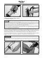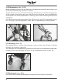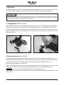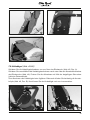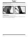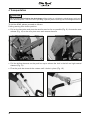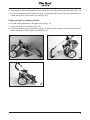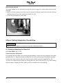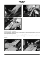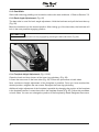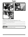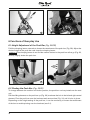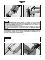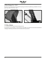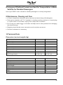
1
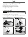
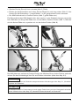
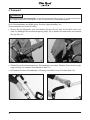
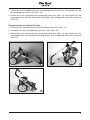
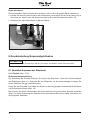
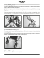
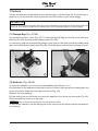
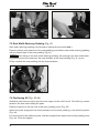
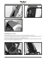
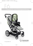
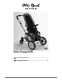
Reha-Buggy KIWI Bedienungsanleitung������������������������������������������������������3 Instructions for Use������������������������������������������������������27 © Otto Bock · 647G491=D/GB-01-0907 Bedienungsanleitung für den Reha-Buggy KIWI Inhalt Seite 1 Allgemeine Informationen..................................................................................................4 1.1 Vorwort.....................................................................................................................4 1.2 Verwendungszweck.................................................................................................4 1.3 Anwendungsgebiet...................................................................................................4 1.4 Haftung....................................................................................................................4 1.5 CE-Konformität........................................................................................................5 1.6 Service.....................................................................................................................5 2 Sicherheitshinweise...........................................................................................................6 2.1 Bedeutung der Symbolik..........................................................................................6 2.2 Allgemeine Sicherheitshinweise..............................................................................6 3 Anlieferung und Herstellung der Gebrauchsfähigkeit.....................................................10 3.1 Auffalten des Reha-Buggys...................................................................................10 4 Transport..........................................................................................................................12 5 Grundeinstellung/Anpassmöglichkeiten.........................................................................14 5.1 Verstellen/Anpassen der Sitzeinheit...................................................................... 14 5.2 Abnehmen/Drehen/Aufsetzen der Sitzeinheit...................................................... 17 6 Funktionen der täglichen Nutzung...................................................................................18 6.1 Höhenverstellung des Schiebebügels...................................................................18 6.2 Schwenken des Schiebebügels.............................................................................18 6.3 Bremsbetätigung...................................................................................................19 6.4 Sitzkantelung.........................................................................................................20 6.5 Lenkstopp..............................................................................................................20 6.6 Beckengurt.............................................................................................................20 7 Optionen...........................................................................................................................21 7.1 Ablagetasche..........................................................................................................21 7.2 Abduktionskeil........................................................................................................21 7.3 Sitzbreiten-Ausgleichspolster................................................................................22 7.4 Positionierungs-Kit.................................................................................................22 7.5 Haltebügel..............................................................................................................23 7.6 Sonnendach...........................................................................................................24 7.7 Weitere Optionen....................................................................................................24 8 Nutzung Ihres Otto Bock Produktes als Sitz beim Transport in Behindertentransportkraftwagen BTW ...........................................................................25 9 Wartung, Reinigung und Pflege........................................................................................25 10 Technische Daten...........................................................................................................25 11 Hinweise zum Wiedereinsatz.........................................................................................26 3 1 Allgemeine Informationen 1.1 Vorwort Mit dem Reha-Buggy KIWI haben Sie sich für ein Qualitätsprodukt entschieden, das Ihnen einen vielseitigen Einsatz im alltäglichen Gebrauch ermöglicht. Bevor Sie Ihren Reha-Buggy KIWI in Gebrauch nehmen, lesen Sie bitte unbedingt die Kapitel „Anlieferung und Herstellung der Gebrauchsfähigkeit“ und „Sicherheitshinweise“. Bitte bewahren Sie die Bedienungsanleitung sorgfältig auf. Das Kapitel „Optionen“ stellt die Anbauteile des KIWI vor, die seinen Einsatzbereich erweitern und den Komfort im Reha-Buggy verbessern können. Ergeben sich darüber hinaus Fragen oder Probleme, wenden Sie sich bitte an Ihren Fachhändler. Technische Änderungen zu der in dieser Bedienungsanleitung beschriebenen Ausführung behalten wir uns vor. 1.2 Verwendungszweck Die Versorgung mit Reha-Buggy bzw. -Buggys ist dann angezeigt, wenn gehunfähige bzw. geheingeschränkte Kinder transportiert werden müssen. Der Reha-Buggy KIWI ist ausschließlich mit den Optionen in der hier aufgeführten Bedienungsanleitung zu kombinieren und umgekehrt. Für Kombinationen mit Medizinprodukten und/oder Zubehörteilen anderer Hersteller außerhalb des Baukastensystems übernimmt Otto Bock keine Haftung. 1.3 Anwendungsgebiet Der Reha-Buggy KIWI wird eingesetzt bei Gehunfähigkeit bzw. stark ausgeprägter Gehbehinderung durch: • Lähmungen • Gliedmaßenverlust • Gliedmaßendefekt und / oder -deformität • Gelenkkontrakturen • Gelenkschäden • sonstige Erkrankungen 1.4 Haftung Der Hersteller haftet nur, wenn das Produkt unter den vorgegebenen Bedingungen und zu den vorgegebenen Zwecken eingesetzt wird. Der Hersteller empfiehlt das Produkt sachgemäß zu handhaben und entsprechend der Anleitung zu pflegen. Für Schäden, die durch Bauteile und Ersatzteile verursacht werden, die nicht vom Hersteller freigegeben wurden, haftet der Hersteller nicht. Reparaturen sind nur von autorisierten Fachhändlern oder vom Hersteller selbst durchzuführen. 4 1.5 CE-Konformität Das Produkt erfüllt die Anforderungen der Richtlinie 93/42 /EWG für Medizinprodukte. Aufgrund der Klassifizierungskriterien für Medizinprodukte nach Anhang IX der Richtlinie wurde das Produkt in die Klasse I eingestuft. Die Konformitätserklärung wurde deshalb von Otto Bock in alleiniger Verantwortung gemäß Anhang VII der Richtlinie erstellt. 1.6 Service Service und Reparaturen am Otto Bock Produkt dürfen nur von einem autorisierten Fachhändler durchgeführt werden. Wenden Sie sich bei Problemen an den Fachhändler, der Ihnen das Produkt angepasst hat. Bei Reparaturen erhalten Sie dort ausschließlich original Otto Bock Ersatzteile. Treten Fragen auf oder kann ein Problem trotz Zuhilfenahme der Bedienungsanleitung nicht gelöst werden, wenden Sie sich bitte an den Kundenservice von Otto Bock (Adresse siehe Umschlaginnenseite oder Umschlagrückseite). Ihr Produkt benötigt eine regelmäßige Wartung /einen regelmäßigen Service (siehe Kap. 9). Ihr autorisierter Otto Bock-Fachhandel: 5 2 Sicherheitshinweise 2.1 Bedeutung der Symbolik WARNUNG VORSICHT HINWEIS Warnungen vor möglichen schweren Unfall- und Verletzungsgefahren. Warnungen vor möglichen Unfall- und Verletzungsgefahren. Warnungen vor möglichen technischen Schäden. Information Hinweise zur Bedienung. Hinweise für das Service-Personal. 2.2 Allgemeine Sicherheitshinweise Information Lesen Sie zuerst die Bedienungsanleitung! Machen Sie sich vor dem Gebrauch zuerst mit Handhabung und Funktion des Produktes vertraut und üben Sie zunächst den Umgang. Sie sind für die Sicherheit Ihres Kindes verantwortlich. Die Sicherheit Ihres Kindes könnte beeinträchtigt werden, wenn Sie diese Hinweise nicht befolgen. Dennoch können nicht alle möglicherweise eintretenden Bedingungen und unvorhersehbaren Situationen abgedeckt werden. WARNUNG Nutzung als Sitz beim Transport in Behindertentransportkraftwagen (BTW) Verletzungsgefahr durch unzulässige Verwendung im BTW. Der Reha-Buggy KIWI ist derzeit nicht für den Transport im BTW zugelassen. Setzen Sie Fahrzeuginsassen während der Fahrt bitte ausschließlich in die im Fahrzeug installierten Sitze mit dazugehörenden Rückhaltesystemen! Bei Nichtbeachtung besteht die Gefahr, dass sowohl der Nutzer als auch alle anderen Fahrzeuginsassen bei einem Unfall verletzt werden könnten. Informationen zum aktuellen Stand unserer Maßnahmen können Sie von Ihrem Fachhändler oder auf der Otto Bock Homepage www.ottobock.de erhalten. WARNUNG Verletzungsgefahr. Dieser Reha-Buggy ist nicht für Kinder mit einem Alter von unter einem Jahr geeignet. Nutzen Sie den Reha-Buggy nur für Kinder ab einem Alter von etwa einem Jahr, die selbstständig sitzen können. WARNUNG Erstickungsgefahr. Achten Sie darauf, dass die Verpackungsmaterialien nicht in Kinderhände gelangen. VORSICHT Gefahren durch Nichtüberprüfung der Funktionsfähigkeit. Im Interesse der Sicherheit ihres Kindes ist die Funktionsfähigkeit des Reha-Buggys grundsätzlich vor jedem Einsatz zu überprüfen. VORSICHT Klemmgefahr. Halten Sie während des Faltvorganges nicht an anderen als den beschriebenen Teilen, insbesondere dem Faltmechanismus fest, da sonst Klemmgefahr besteht! VORSICHT Verletzungsgefahr durch Überladung. Der Reha-Buggy ist nur für den Transport eines Kindes zugelassen. 6 VORSICHT Sturzgefahr. Lassen Sie Ihr Kind nie unbeaufsichtigt, auch dann nicht, wenn es durch Begurtung gesichert ist und die Bremsen festgestellt sind. Gefahr beim Befahren von Treppen / Hindernissen WARNUNG Sturzgefahr. Sind Einrichtungen wie z. B. Auffahrrampen oder Aufzüge neben oder über Treppen vorhanden, so sind diese zu benutzen. Fehlen solche Einrichtungen, so ist das Hindernis durch Tragen (zwei Helfer) zu überwinden. VORSICHT Sturzgefahr durch falsches Anheben. Begleitpersonen dürfen den Reha-Buggy nur an fest vernieteten oder verschraubten Bauteilen des Fahrgestells anheben. Gefahren beim Einstieg VORSICHT Verletzungsgefahr durch fehlerhaftes Auffalten. Faltsicherungen müssen vor Benutzung des RehaBuggys fest eingerastet sein. VORSICHT Verletzungsgefahr durch Einstieg über das Fußbrett. Das Fußbrett darf nicht zum Ein- und Aussteigen benutzt werden. VORSICHT Kippgefahr. Betätigen Sie vor dem Ein- und Aussteigen immer die Bremsen des Reha-Buggys. Gefahr beim Fahren / Abstellen WARNUNG Sturzgefahr bei Abnehmen des Sitzes. Der Schwerpunkt des Sitzes kann sich beim Abnehmen so ungünstig verlagern, dass der Sitz abkippen und ein darin befindliches Kind herausfallen kann. Entnehmen Sie daher Ihr Kind vor jedem Abnehmen des Sitzes aus dem Reha-Buggy. WARNUNG Überschlaggefahr durch zu schnelles Schieben. Lenkbare Vorderräder können bei höheren Geschwindigkeiten anfangen zu flattern und zu einem abrupten Abstoppen und Überschlagen des Reha-Buggys nach vorne führen. Schieben Sie den Reha-Buggy daher nur in normaler Gehgeschwindigkeit. Es ist unzulässig, den Buggy während des Schiebens loszulassen oder von sich abzustoßen. WARNUNG Gefahr durch unzulässigen Gebrauch. Der Gebrauch eines Reha-Buggys über die typische Nutzung hinaus kann gefährlich sein. Zum Joggen, Rennen, Skaten o. ä. ist dieses Produkt nicht geeignet. 7 VORSICHT Unfallgefahr beim Befahren von Steigungen/Gefälle. Schenken Sie dem Befahren von Steigungen und Gefällen erhöhte Aufmerksamkeit. Konkrete Gefährdungen hierbei sind: • Herausfallen des Kindes, • Umkippen des Reha-Buggys, • Wegrollen des Reha-Buggys. VORSICHT Kippgefahr durch Schwerpunktverlagerungen. Achten Sie darauf, dass Ihr Kind sich beim Ergreifen von Gegenständen (die vor, seitlich oder hinter dem Reha-Buggy liegen) nicht zu weit aus dem RehaBuggy lehnt. VORSICHT Kippgefahr beim ungebremsten Fahren gegen Hindernisse. Vermeiden Sie ein ungebremstes Fahren gegen ein Hindernis (Stufe, Bordsteinkante). Fahren Sie an das Hindernis heran und heben Sie die vorderen Räder an. Schieben sie den Buggy weiter, bis die hinteren Räder das Hindernis berühren. Heben Sie den Buggy wieder auf die vorderen Räder und schieben Sie den Buggy über das Hindernis. VORSICHT Kippgefahr beim Abstellen. Der Reha-Buggy sollte, sofern sich ein Kind im Sitz befindet, grundsätzlich nur auf horizontalen, ebenen Flächen abgestellt werden. Auf Steigungen kann in Liegeposition die Gefahr eines Kippens nach hinten bestehen. Sollte es einmal unvermeidlich sein, ihn auf einer Steigung abzustellen, achten Sie bitte darauf, dass dabei der Sitz in eine aufrechte Position gebracht wird. Die statische Stabilität reicht bis 12° Neigung. VORSICHT Kippgefahr durch Schwerpunktverlagerungen. Das Anhängen von schweren Taschen o.ä. am Schiebebügel kann die Stabilität negativ beeinflussen und ist zu unterlassen. HINWEIS Beschädigung durch Fahren gegen ein Hindernis (Stufe, Bordsteinkante). Ungebremstes Fahren gegen Hinderisse könnte zu technischen Schäden führen und ist daher zu unterlassen. Sollten sich die lenkbaren Räder an einem Hindernis quer zur Fahrtrichtung ausgerichtet haben, kann ein Nachschieben zu einer Beschädigung der Lenkradgabeln führen. Heben Sie in einem solchen Fall die Räder an und überwinden so das Hindernis. Gefahr durch Montage- / Einstellfehler VORSICHT Verletzungsgefahr durch falsch montierten Schiebebügel. Die höchste Einstellmöglichkeit des Schiebebügels ist durch eine Auszugsbegrenzung vorgegeben. Es dürfen keine Einstellungen über diesen Bereich hinaus erfolgen. VORSICHT Verletzungsgefahr durch unverschlossene Klemmhebel. Die Klemmhebel der Schiebebügelhöhenverstellung müssen nach jeder Höhenverstellung wieder fest verschlossen (eingerastet) werden. 8 Information Achten Sie nach allen Einstellungen darauf, Schrauben und Muttern wieder fest anzuziehen. Gefahr durch Feuer / Hitze und Kälte VORSICHT Verbrennungsgefahr beim Umgang mit Feuer. Sitz- und Rückenpolster könnten sich entzünden. Jegliche Zündquellen, insbesondere brennende Zigaretten, sollten grundsätzlich ferngehalten werden. VORSICHT Vorsicht bei extremen Temperaturen. Der Reha-Buggy kann sich durch Sonneneinstrahlung stark aufheizen. In extremer Kälte besteht die Gefahr von Unterkühlungen. HINWEIS Beschädigung durch extreme Temperaturen. Wird Ihr Reha Buggy extremen Temperaturen ausgesetzt, können sich die Materialeigenschaften und somit auch die Festigkeit der Kunststoffteile verändern. Eine längere Lagerung bei extremer Kälte (-30°C) oder Hitze (+90°C) ist deshalb zu vermeiden. Warnungen vor Schäden am Reha-Buggy VORSICHT Verletzungsgefahr durch Überladung. Die maximale Belastbarkeit der Sitzeinheit (Zuladung) beträgt 25 kg. Die maximale Belastbarkeit des Buggy (inklusive Zuladung) beträgt 30 kg. HINWEIS Beschädigung durch aufliegende Gegenstände. Werden Hilfsmittel im zusammengefalteten Zustand transportiert, kann das Gewicht aufliegender Gegenstände zu Deformationen und in der Folge zu Problemen beim Auffalten führen. Legen Sie niemals schwere Gegenstände auf ein zusammengefaltetes Rehagerät. HINWEIS Schäden durch Überladung. Die Ablagetasche darf mit max. 5 kg beladen werden. HINWEIS Schäden durch falsche Verpackung. Bitte nutzen Sie beim Versand des Produktes nur die Originalverpackung. Information Alle Zubehör- und Anbauteile reduzieren die verbleibende Zuladekapazität. 9 3 Anlieferung und Herstellung der Gebrauchsfähigkeit Ihr Reha-Buggy wird in der Regel komplett montiert, eingeklappt und mit evtl. demontierten großen Rädern/demontiertem Sitz angeliefert (Abb. 1). In der Originalverpackung finden Sie folgende Komponenten vor: • Untergestell mit Lenkrädern und Sitzeinheit (zusammengefaltet) • Anleitung und benötigtes Werkzeug • Zubehör je nach Bestellung Entfernen Sie bitte zunächst vorsichtig die Transportsicherungen und Verpackungen. 3.1 Auffalten des Reha-Buggys VORSICHT Klemmgefahr beim Auffalten. Fassen Sie während des Faltvorgangs nur an die beschriebenen Teile. Insbesondere beim Hineingreifen in den Faltmechanismus besteht Klemmgefahr. Zum Auffalten des Reha-Buggys gehen Sie bitte folgendermaßen vor: • Heben Sie den Schiebebügel an und drücken Sie gleichzeitig das Untergestell an der Querstrebe herunter. Das Fahrgestell des Reha-Buggys faltet sich soweit auf, bis der Schiebebügel einrastet (Abb. 2/3). • Stecken Sie die großen Räder auf, bis der Federmechanismus einrastet (Abb. 4). 1 3 10 2 4 • Stecken Sie den Sitz auf, bis er einrastet (Abb. 5, Pfeile). • Richten sie die Rückenlehne auf, indem Sie das Bügelrohr nach oben ziehen (Abb. 6). Nun können Sie die Rückenlehne – je nach Bedarf – in der gewünschten Position einrasten. • Der KIWI befindet sich in Outdoor-Position (Abb. 7, große Räder vorn). Eine Besonderheit des KIWI besteht darin, das man ihn in zwei Schieberichtungen verwenden kann. Befinden sich die großen Räder vorn, ist der KIWI in Outdoor-Position (Abb. 7). Befinden sich die kleinen Räder vorn, sprechen wir von der Indoor-Position (Abb. 8). 5 6 7 8 Der KIWI faltet sich zunächst in Outdoor-Position auf. Möchten Sie zur Indoor-Position wechseln, müssen Sie den Schiebebügel über Sitz und Rücken schwenken (siehe dazu Kap. 6.2). Information Näheres zum Einstellen der Sitzeinheit entsprechend den Anforderungen siehe Kap. 5.1 „Verstellen/ Anpassen der Sitzeinheit”. Information Der Sitz kann sowohl in Fahrtrichtung als auch gegen Fahrtrichtung mit dem Untergestell verbunden werden. Näheres dazu siehe Kap. 5.2 „Abnehmen/Drehen/Aufsetzen der Sitzeinheit“. 11 4 Transport VORSICHT Klemmgefahr beim Zusammenfalten. Fassen Sie während des Faltvorgangs nur an die beschriebenen Teile. Insbesondere beim Hineingreifen in den Faltmechanismus besteht Klemmgefahr. Zum Zusammenfalten des KIWI gehen Sie bitte folgendermaßen vor: Zusammenfalten aus Indoor-Position: • Ziehen Sie am Bügelrohr und schwenken Sie den Sitz so weit wie möglich nach vorn (Abb. 9). Betätigen Sie die Sitzentriegelung (Abb. 10) an beiden Schwenkarmen und nehmen Sie den Sitz ab. 9 10 • Ziehen Sie die Schiebeelemente am Schiebebügel nach oben. Dadurch löst sich die Arretierung im linken und rechten Zentralelement (Abb. 11). • Schwenken Sie den Schiebebügel in Richtung Lenkräder, bis er einrastet (Abb. 12). 11 12 12 • Ziehen Sie die Schiebeelemente am Schiebebügel erneut nach oben. Schwenken Sie den Schiebebügel ganz nach unten (Abb. 13). • Ziehen Sie an der Querstrebe das Untergestell nach oben (Abb. 14) und klappen Sie das Untergestell über die Querstrebe Richtung Boden. Das Untergestell faltet sich zusammen (Abb. 15). Zusammenfalten aus Outdoor-Position: • Ziehen Sie die Schiebeelemente am Schiebebügel nach oben (Abb. 11). • Schwenken Sie den Schiebebügel ganz nach unten (Abb. 13). • Ziehen Sie an der Querstrebe das Untergestell nach oben (Abb. 14) und klappen Sie das Untergestell über die Querstrebe Richtung Boden. Das Untergestell faltet sich zusammen (Abb. 15). 13 14 15 13 Räder abnehmen: Um ein besonders kleines Packmaß zu erreichen, können Sie die großen Räder abnehmen. • Greifen Sie dazu mit einer Hand an die Hinterachse und drücken Sie die Feder nach innen in die Achse ein. Nach Lösen der Arretierung können Sie das Rad abnehmen (Abb. 16). • Verfahren Sie auf beiden Seiten in gleicher Weise. 16 5 Grundeinstellung/Anpassmöglichkeiten Information Achten Sie nach allen Einstellungen darauf, Schrauben und Muttern wieder fest anzuziehen. 5.1 Verstellen/Anpassen der Sitzeinheit 5.1.1 Sitztiefe (Abb. 17-21) Stufenlose Hauptverstellung: Zur Verstellung der Sitztiefe entfernen Sie zuerst das Sitzpolster. Lösen Sie die Druckknöpfe des Sitzpolsters (Abb. 17). Entfernen Sie das Sitzpolster von der Klettunterlage und legen Sie es ab. Entfernen Sie ggf. den Beckengurt. Lösen Sie die Schraube in der Mitte des Sitzes mit dem beigelegten Innensechskant-Schlüssel und Schraubenschlüssel (Abb. 18). Nun können Sie durch Verschieben des Sitzvorderteils die gewünschte Sitztiefe einstellen (Abb. 19). Nach Einstellung der Sitztiefe die Innensechskant-Schraube wieder festziehen und die Sitzpolster aufkletten. 14 17 18 19 Einstellung am Knierohr: Für einen größeren Verstellbereich kann die Sitztiefe zusätzlich durch Verschieben des Knierohrs am Oberschenkelrohr eingestellt werden. Lösen Sie die Schraube an der Seite des Knierohrs (Abb. 20). Gehen Sie an beiden Seiten entsprechend vor. Nun können Sie das Knierohr um 2 cm verschieben und die Schraube in die dafür vorgesehene Bohrung fest einschrauben (Abb. 21). 20 21 15 5.1.2 Sitzbreite Zur Verkleinerung der Sitzbreite Größe 1 können Ausgleichspolster verwendet werden. Siehe dazu Kap. 7.3. 5.1.3 Rückenwinkelverstellung (Abb. 22) Die Verstellung der Rückenwinkels erfolgt mit Hilfe des Bügelrohrs. Halten Sie die Rückenlehne fest und ziehen Sie das Bügelrohr nach oben (Abb. 22). Nun kann die Rückenlehne in die gewünschte Position gebracht werden. Nach Loslassen des Bügelrohrs rastet der Rücken in die nächstmögliche Stellung ein. Information Vergewissern Sie sich durch Drücken auf das Bügelrohr nach unten (Abb. 22), dass die Rückenlehne komplett eingerastet ist. 22 5.1.4 Höhenverstellung des Fußbretts (Abb. 23-25) Öffnen Sie den Klettverschluss der Unterschenkelbespannung (Abb. 23). Lösen Sie den Gewindestift am Knierohr (Abb. 24). Gehen Sie an beiden Seiten entsprechend vor. Nun können Sie die Höhe des Fußbretts stufenlos einstellen. Ziehen Sie nach der Einstellung die Gewindestifte wieder fest an. Justieren Sie die Unterschenkelbespannung neu. Die Höhenverstellung des Fußbretts kann zusätzlich durch Versetzen des Fußbretts an der Fußbrettaufnahme eingestellt werden. Lösen Sie dazu die Schraube der Fußbrettaufnahme (Abb. 25). Gehen Sie an beiden Seiten entsprechend vor. Sie können nun das Fußbrett um 2 cm versetzen. Ziehen Sie nach Einstellung die Schrauben wieder fest an. 16 23 24 25 5.2 Abnehmen/Drehen/Aufsetzen der Sitzeinheit (Abb. 26/27) Zur individuellen Nutzung haben Sie die Möglichkeit, die Sitzeinheit in zwei Richtungen (Abb. 26: Blickrichtung in / gegen die Fahrtrichtung) auf das Untergestell aufzusetzen. Zum Abnehmen der Sitzeinheit drücken Sie die Sitzentriegelung an beiden Schwenkarmen (Abb. 27). Ziehen Sie den Sitz nach oben heraus. Drehen Sie den Sitz. Setzen Sie die Sitzeinheit wieder auf den Schwenkarm auf und drücken Sie den Sitz bis zum Einrasten nach unten. Information Mit einem kurzen Ruck können Sie den festen Sitz der Sitzeinheit überprüfen. 17 26 27 6 Funktionen der täglichen Nutzung 6.1 Höhenverstellung des Schiebebügels (Abb. 28/29) Zum Lösen der Befestigung des Schiebebügels klappen Sie die Klemmhebel nach außen (Abb. 28). Stellen Sie die gewünschte Höhe des Schiebebügels ein und verschließen Sie die Klemmhebel wieder. Sollten die Klemmhebel nicht auf Anhieb die Rastkerben im Schiebebügel finden (Abb. 29, Pfeile), rütteln sie leicht am Schiebebügel. Information 28 29 6.2 Schwenken des Schiebebügels (Abb. 30/31) Zum Wechseln zwischen der Outdoor- und Indoor-Position kann der Schiebebügel über die Sitzeinheit geschwenkt werden. Ziehen Sie die Schiebeelemente am Schiebebügel nach oben (Abb. 30). Dadurch löst sich die Arretierung im linken und rechten Zentralelement. Schwenken Sie den Schiebebügel über Rücken und Sitzfläche (Abb. 31), bis er einrastet. Je nach Höheneinstellung des Schiebebügels kann es erforderlich sein, die Befestigung des Bügels zu lösen, um diesen über den Rücken schwenken zu können (siehe 6.1). 18 30 31 6.3 Bremsbetätigung (Abb. 32/33) HINWEIS Beschädigung durch falsche Bremsbetätigung. Wird der Bremshebel zum Betätigen der Bremse nicht ausreichend betätigt, kann es zum Schleifen des Bremsbolzens am Bremskranz und in der Folge zu übermäßigem Verschleiß kommen. Bremse immer um 90° (bis zum Anschlag) drücken, damit die Bremse vollständig einrasten und ihre volle Bremswirkung erzielen kann. Wird der Bremshebel beim Lösen der Bremse nicht vollständig in seine Ausgangsposition zurückgeführt, kann es zum Schleifen des Bremsbolzens am Bremskranz und in der Folge zu übermäßigem Verschleiß kommen. Bremse immer vollständig lösen. Zum Herausnehmen des Kindes und zum Abstellen des Reha-Buggys auf unebenen Flächen ist die Bremse zu betätigen. Ziehen Sie dazu den Bremshebel nach unten, bis dieser senkrecht zur Schiebestange steht (Abb. 32), der Bowdenzug gespannt und die Räder blockiert sind. Zum Lösen der Bremse drücken sie den seitlichen Knopf am Bremshebel und ziehen diesen zeitgleich nach oben, bis dieser sich parallel zur Schiebeeinheit befindet (Abb. 33). Information Sollte sich der Bremshebel nicht auf Anhieb in die senkrechte Position ziehen lassen, schieben Sie den Wagen leicht hin und her, damit die Bremsbolzen die richtigen Positionen in den Bremsscheiben finden. 32 33 19 6.4 Sitzkantelung (Abb. 34/35) Mit der Sitzkantelung können Sie die Sitzeinheit in eine aktive oder passive Position neigen, ohne die Rückenwinkeleinstellung verändern zu müssen. Ergreifen Sie dazu mit einer Hand die Rückenlehne. Schieben Sie nun den Sicherungsschieber mit der anderen Hand vertikal nach unten (Abb. 34) bis zum Anschlag. Durch anschließendes Hineindrücken des Sicherungsschiebers in Richtung Sitz wird der Kantelungsmechanismus freigegeben. Nach gewünschter Kantelungseinstellung (Abb. 35) lassen Sie den Sicherungsschieber wieder los – er springt in die Ursprungsposition zurück. Auch die Sitzkantelung ist nun eingerastet. 34 35 6.5 Lenkstopp (Abb. 36) Die Lenkräder können in beiden Fahrtrichtungen arretiert werden. Diese Funktion erhöht die Spurtreue auf unebenem Untergrund. Zum Schließen der Lenkradarretierung werden die Lenkräder auf Geradeauslauf ausgerichtet. Schieben Sie nun den Lenkstopp nach unten, bis der Geradeauslauf fixiert ist (Abb. 36). 36 6.6 Beckengurt (ohne Abb.) Das Öffnen und Schließen des Beckengurts erfolgt durch Druck auf das Gurtschloss. 20 7 Optionen Ihr Reha-Buggy kann durch bestimmte Zubehörteile ergänzt werden. Wir möchten Ihnen eine Auswahl unserer Zubehörteile vorstellen, die Ihnen die Benutzung erleichtern können. Information Gurte an Zubehörteilen sind meist großzügig bemessen, um allen Möglichkeiten gerecht zu werden. Überschüssige Gurtenden können abgeschnitten und mit einer Flamme (Feuerzeug) durch Verschmelzen der Schnittkante gegen Ausfransen gesichert werden. 7.1 Ablagetasche (Abb. 37/38) Die Ablagetasche ist mit einer Abdeckung versehen (Abb. 37). Zum Reinigen der Ablagetasche nehmen Sie Abdeckung ab und öffnen Sie die Klettverschlüsse der Haltebänder (Abb. 38). Zur Befestigung führen Sie die entsprechenden Bänder rechts und links um das mittlere Rahmenrohr sowie um das vordere Rahmenrohr (Abb. 38). Verschließen Sie die Bänder mit den Klettverschlüssen. 37 38 7.2 Abduktionskeil (Abb. 39/40) Zur Befestigung des Abduktionskeils entnehmen Sie zuerst das Sitzpolster (siehe Kap. 5.1.1). Stecken Sie die Halterung für den Abduktionskeil mittig auf das Querrohr des Sitzvorderteils auf und verschrauben Sie es. Schieben Sie die Abdeckkappe auf die Mutter (Abb. 39). Kletten Sie das Sitzpolster wieder auf. Ziehen Sie den Rastbolzen an der Halterung und führen Sie den Abduktionskeil von oben in die Halterung ein (Abb. 40). Drücken Sie den Abduktionskeil bis zum Anschlag herunter. Information Achten Sie darauf, dass der Rastbolzen vollständig eingerastet ist. Zum Abnehmen ziehen Sie den Rastbolzen nach vorne und gleichzeitig den Abduktionskeil nach oben heraus. 21 39 40 7.3 Sitzbreiten-Ausgleichspolster (Abb. 41) Zur Verkleinerung der Sitzbreite Größe 1 können Ausgleichspolster verwendet werden. Öffnen Sie die seitlichen Druckknöpfe des Sitzpolsters und schieben Sie die Ausgleichspolster auf die Seitenlaschen der Sitzpolster auf (Abb. 41). Beachten Sie, dass nach dem Aufstecken die Öffnung der Ausgleichspolster über dem Druckknopf des Sitzpolsters liegen muss (Abb. 41, Pfeil). Information Zum Abschluss wird das Sitzpolster mit Hilfe der Druckknöpfe wieder befestigt. 41 7.4 Positionierungs-Kit (Abb. 42-44) Um dem Rumpf des Kindes mehr Unterstützung zu geben, können zusätzliche Polsterteile verwendet werden. Bei der Positionierung kann das Kind im Sitz bleiben. Öffnen Sie die hinten liegenden Reißverschlüsse der Rückenpolsterabdeckung (Abb. 42). Kletten Sie die Polsterteile in gewünschter Position in das Rückenpolster ein (Abb. 43). Um den zusätzlichen Polsterteilen Halt zu geben, schieben Sie die mitgelieferte Rückenplatte in die Rückenpolsterabdeckung ein (Abb. 44). Verschließen Sie die Reißverschlüsse wieder. 22 42 43 44 7.5 Haltebügel (Abb. 45/46) Schieben Sie die Haltebügelaufnahmen von vorn über das Rückenrohr (Abb. 45, Pos. A). Schieben Sie anschließend die Haltebügelaufnahmen nach unten über die Kunststoffaufnahme des Rückenrohrs (Abb. 46). Fixieren Sie die Aufnahmen mit Hilfe der beigefügten Schrauben (inklusive Distanzstücke). Zum Abnehmen des Haltebügels beim täglichen Gebrauch drücken Sie beidseitig die Arretierknöpfe (Abb. 45, Pos. B). Nun können Sie den Haltebügel nach vorn herausziehen. A A B 45 46 23 7.6 Sonnendach (Abb. 47/48) Klippen Sie das Sonnendach (Abb. 47) in den dafür vorgesehenen Aussparungen der Rückenbespannung (Abb. 48) an das Rückenrohr. 47 48 7.7 Weitere Optionen • Fünfpunktgurt zur stärkeren Fixierung/Sitzsicherheit Dieses und weitere optionale Anbauteile sind im Bestellblatt und im Zubehörkatalog enthalten. Anleitungen zum Anbau liegen den Produkten bei. 24 8 Nutzung Ihres Otto Bock Produktes als Sitz beim Transport in Behindertentransportkraftwagen BTW Die Verwendung Ihres KIWI im BTW wird momentan noch geprüft. 9 Wartung, Reinigung und Pflege • Alle Rahmen- und Kunststoffteile dürfen nur mit milden Reinigungsmitteln gesäubert werden. • Polsterteile können bei 40 °C gewaschen werden, in der Waschmaschine jedoch nur im Waschsack oder Kopfkissenbezug. Meist reicht das Abwischen mit einem feuchten Tuch. • Keine Benutzung im Salzwasser. Vermeiden Sie nach Möglichkeit, dass Sand oder sonstige Schmutzpartikel die Lagerung der Räder angreifen können. • Überprüfen Sie bitte regelmäßig die Schraub- und Nietverbindungen auf festen Sitz. • Weitere Wartungsmaßnahmen sind nicht erforderlich. 10 Technische Daten Maße (cm) und Gewichte (kg) Untergestell Schiebebügelhöhe Gesamtbreite Raddurchmesser vorn Raddurchmesser hinten Kippung der Sitzaufnahme Zuladung Gewicht Faltmaße Straßengestell ohne Sitz (ohne große Räder) Größe 1 96 – 116 58 15 30 0° – 30° 30 7,2 80 x 58 x 37 (80 x 58 x 22) Größe 2 96 – 116 63 15 30 0° – 30° 30 7,5 80 x 63 x 37 (80 x 63 x 22) Sitzeinheit Sitztiefe Sitzbreite Unterschenkellänge Höhe Rückenlehne Neigung Rückenlehne Zuladung Gewicht Faltmaß (L x B x H) Größe 1 12 – 22 27 14 – 20 63 0°– 30° 25 3,6 65 x 44 x 26 Größe 2 20 – 28 32 19,5 – 29,5 68 0°– 30° 25 4,3 70 x 49 x 30 25 11 Hinweise zum Wiedereinsatz VORSICHT Gefahr durch unsachgemäße Anwendung. Sitzpolster, die direkt mit der Haut in Berührung kommen, können bei Gebrauch des Produktes an einer weiteren Person funktionale bzw. hygienische Risiken verursachen. Sie sind bei einem Wiedereinsatz auszutauschen. Das Produkt ist zum Wiedereinsatz geeignet. Produkte im Wiedereinsatz unterliegen – ähnlich wie gebrauchte Maschinen oder Fahrzeuge – einer besonderen Belastung. Die Merkmale und Leistungen dürfen sich nicht derart ändern, dass die Sicherheit der Patienten und ggf. Dritter während der Lebensdauer gefährdet wird. Aufgrund der Marktbeobachtung und dem Stand der Technik hat der Hersteller den Einsatz des Produktes unter Einhaltung des bestimmungsgemäßen Gebrauchs und unter Einbeziehung der Service- und Wartungsvorgaben auf 4 Jahre kalkuliert. Zeiten der Einlagerung beim Fachhändler oder Kostenträger gehören nicht dazu. Dabei ist deutlich hervorzuheben, dass das Produkt bei entsprechender Pflege und Wartung weit über diesen definierten Zeitraum hinaus zuverlässig ist. Für den Wiedereinsatz ist das betreffende Produkt zunächst gründlich zu reinigen und zu desinfizieren. Anschließend ist das Produkt von einem autorisierten Fachmann auf Zustand, Verschleiß und Beschädigungen zu überprüfen. Sämtliche verschlissenen und beschädigten Teile sowie für den Anwender unpassende/ungeeignete Komponenten sind auszutauschen. Ein Serviceplan, Detailinformationen und Angaben zu den benötigten Werkzeugen sind der Serviceanleitung zu entnehmen. 26 Instructions for Use for the KIWI Rehab Buggy Contents Page 1 General Information.........................................................................................................28 1.1 Preface...................................................................................................................28 1.2 Intended Use..........................................................................................................28 1.3 Field of Application................................................................................................28 1.4 Liability...................................................................................................................28 1.5 CE Conformity........................................................................................................29 1.6 Service...................................................................................................................29 2 Safety Instructions...........................................................................................................30 2.1 Explanation of Symbols..........................................................................................30 2.2 General Safety Instructions...................................................................................30 3 Delivery / Preparing the Rehab Buggy for Use...............................................................34 3.1 Unfolding the Rehab Buggy...................................................................................34 4 Transportation..................................................................................................................36 5.1 Adjusting/Adapting the Seat Unit..........................................................................38 5.2 Removing / Turning / Mounting the Seat Unit....................................................... 41 6 Functions of Everyday Use...............................................................................................42 6.1 Height Adjustment of the Push Bar.......................................................................42 6.2 Pivoting the Push Bar............................................................................................42 6.3 Wheel Lock Operation............................................................................................43 6.4 Seat Tilt..................................................................................................................44 6.5 Caster Swivel Lock.................................................................................................44 6.6 Lap Belt..................................................................................................................44 7 Options���������������������������������������������������������������������������������������������������������������������������� 45 7.1 Storage Bag............................................................................................................45 7.2 Abductor.................................................................................................................45 7.3 Seat Width Reducing Padding...............................................................................46 7.4 Positioning Kit........................................................................................................46 7.5 Grabrail..................................................................................................................47 7.6 Sun Canopy............................................................................................................48 7.7 Other Options.........................................................................................................48 8 Using your Otto Bock Product as a Seat for Transportation in Motor Vehicles for Disabled Passengers ......................................................................................................49 9 Maintenance, Cleaning and Care....................................................................................49 10 Technical Data...............................................................................................................49 11 Information on Re-use...................................................................................................50 27 1 General Information 1.1 Preface The KIWI rehab buggy is a quality product offering versatile use in everyday life. Before you start using your KIWI rehab buggy, please make sure you read the sections “Delivery / Preparing the Rehab Buggy for Use” and “Safety Instructions”. Please keep these instructions for use in a safe place. The section “Options” presents additional parts for the KIWI, which may extend the range of application and increase the comfort in the rehab buggy. If you have any questions or problems, please contact your specialist dealer. Technical changes to the design described in these instructions for use are reserved. 1.2 Intended Use Rehab buggies are generally indicated for children who are unable to walk or have a walking impediment and need to be transported. The KIWI rehab buggy may only be combined with the options mentioned in these instructions for use and vice versa. Otto Bock assumes no liability for combinations with medical products and/or accessories from other manufacturers outside of the modular system. 1.3 Field of Application The KIWI rehab buggy is suitable for people who are unable to walk or have severe walking impediments due to: • Palsies/Paralyses • Loss of limbs • Defective and/or deformed limbs • Joint contractures • Joint defects • Other diseases 1.4 Liability The manufacturer’s warranty applies only if the product has been used under the conditions and for the purposes described. The manufacturer recommends that the product be used and maintained according to the instructions for use. The manufacturer is not responsible for damages caused by components and spare parts not approved by the manufacturer. Repairs must be carried out exclusively by authorised dealers or by the manufacturer. 28 1.5 CE Conformity This product meets the requirements of the 93/42/EEC guidelines for medical devices. This product has been classified as a class I device according to the classification criteria outlined in appendix IX of the guidelines. The declaration of conformity was therefore created by Otto Bock with sole responsibility according to appendix VII of the guidelines. 1.6 Service Service and repairs on the Otto Bock product may only be carried out by an authorised dealer. Should any problems arise, please contact the supplier of your product. Any necessary repairs will be made exclusively with authentic Otto Bock spare parts there. Should you have any questions or a problem that cannot be resolved despite using the instructions for use, please contact Otto Bock Customer Service (see inside cover or back side of cover for address). Your product requires regular maintenance / regular service (see Section 9). Your authorised Otto Bock dealer: 29 2 Safety Instructions 2.1 Explanation of Symbols WARNING CAUTION NOTICE Warnings regarding possible risks of severe accident or injury. Warnings regarding possible risks of accident or injury. Warnings regarding possible technical damage. Information Information regarding operation. Information for service personnel. 2.2 General Safety Instructions Information Please read the instructions for use first! Before using the product, you should become familiar with the handling, function and use of the product. You are responsible for the safety of your child. You may compromise the safety of your child if you do not observe these instructions. However, it is impossible to protect against and avoid all unforeseeable circumstances and situations. WARNING Use as a seat for transportation in a vehicle for the disabled Risk of injury as a result of unauthorised use in a motor vehicle for the disabled. The KIWI rehab buggy has not yet been approved for transportation in a vehicle for the disabled. Users of the product must always transfer to the seats installed in the motor vehicle with the corresponding vehicle restraint systems! Non-observance of these instructions could lead to injury of the user, as well as of all other passengers in the motor vehicle, in case of an accident. You can get information on the present state of our measures from your specialist dealer or on the Otto Bock Homepage www.ottobock.com. WARNING Risk of injury. This rehab buggy is not suited for children aged less than one year. Use the rehab buggy only for children from the age of about 1 who are able to sit independently. WARNING Danger of suffocation. Make sure to keep packaging material away from children. CAUTION Danger as a result of failure to perform functional testing. In the interest of your child‘s safety, the correct function of the rehab buggy is to be checked before every use. CAUTION Risk of pinching. While folding the rehab buggy, do not hold on to other parts than the ones described, especially the folding mechanism. Otherwise, injury may result! CAUTION Risk of injury due to overload. The rehab buggy has been approved for the transport of only one child. 30 CAUTION Risk of falling. Never leave your child unattended, even if the belts are in use and the wheel locks are engaged. Danger when overcoming stairs / obstacles WARNING Risk of falling. If devices such as ramps or elevators are available next to or above stairs, they should be used. If wheelchair-friendly access is missing, two attendants must carry the rehab buggy over the obstacle. CAUTION Risk of falling as a result of lifting the rehab buggy incorrectly. Attendants must lift the rehab buggy only by chassis parts that are firmly riveted or screwed. Danger when getting into the rehab buggy CAUTION Risk of injury due to unfolding the rehab buggy incorrectly. Before using the rehab buggy, the folding guards must be firmly locked in place. CAUTION Risk of injury as a result of using the footplate for getting into the rehab buggy. The footplate must not be used for getting into or out of the buggy. CAUTION Risk of tipping. Before getting into and out of the rehab buggy always operate the wheel locks. Danger while driving / parking WARNING Risk of falling when removing the seat. The seat‘s centre of gravity may shift unfavourably when removing the seat so that the seat can tilt and a child sitting in the seat fall out. Therefore, always take your child out of the rehab buggy before removing the seat. WARNING Risk of tipping over when pushing too quickly. Swivelling front wheels might begin to wobble at higher speeds and lead to an abrupt stop, causing the rehab buggy to tip over forwards. Therefore, push the rehab buggy only at normal walking speed. It is not permissible to let go of the push bar while pushing the buggy or to thrust it away from you. WARNING Danger as a result of improper use. Using the rehab buggy beyond the normal can be dangerous. The product is unsuitable for jogging, running, skating etc. 31 CAUTION Risk of accident when ascending or descending inclines. Pay particular attention when ascending or descending inclines to prevent: • the child from falling out of the rehab buggy; • the rehab buggy from tipping over; • the rehab buggy from rolling away. CAUTION Risk of tipping due to centre of gravity shifting. When your child reaches for objects in front, to the side or behind the rehab buggy, make sure that he or she does not lean out of it too far. CAUTION Risk of tipping when driving against obstacles without braking. Do not drive into obstacles (including steps, curbs) without braking. Approach the obstacle and lift the front wheels. Continue to push the buggy until the rear wheels contact the obstacle. Then lift the buggy onto the front wheels and push the buggy over the obstacle. CAUTION Risk of tipping when parking the rehab buggy. Park the rehab buggy with a child sitting in it only on level surfaces. When parked on a incline, there is a risk that the rehab buggy can tip over backwards when in a reclined position. If you have to park the rehab buggy on an incline, make sure that you bring the seat to an upright position. Static stability is given up to 12° inclination. CAUTION Risk of tipping due to centre of gravity shifting. Attaching heavy bags or other weight to the push bar can adversely affect stability and is not allowed. NOTICE Damage caused by driving against obstacles (including steps, curbs). Driving against obstacles without braking could lead to technical damage and is therefore not allowed. If the casters at an obstacle turn transverse to the pushing direction, pushing any further can damage the caster forks. In such a case, overcome the obstacle by lifting the wheels. Danger as a result of incorrect assembly or setting CAUTION Risk of injury as a result of incorrectly mounted push bar. The maximum height setting of the push bar is predetermined by an extension limit. Adjustments beyond this range are not permitted. CAUTION Risk of injury if the clamping levers have not been closed. The clamping levers of the push bar height adjustment must be firmly closed (locked in place) each time the height setting has been changed. Information Make sure to firmly retighten all screws and nuts after making adjustments. 32 Danger caused by fire / heat and cold CAUTION Risk of burns when near to fire. The seat and back padding might catch fire. Keep the rehab buggy away from all sources of ignition, especially lit cigarettes. CAUTION Be careful in case of extreme temperatures. When exposed to the sun, the rehab buggy can get very hot. In extreme cold, there is a risk of hypothermia. NOTICE Risk of damage due to extreme temperatures. Should your rehab buggy become exposed to extreme temperatures, the material properties and thereby the strength of the plastic components may change. Therefore, avoid keeping the buggy in extreme cold (-30°C) or heat (+90°C) for extended period of times. Warnings regarding damage to the rehab buggy CAUTION Risk of injury due to overload. The maximal load capacity of the seat unit (payload) unit is 25 kg/55 lbs. The maximal load capacity of the buggy (including payload) is 30 kg/66 lbs. NOTICE Damage caused by objects lying upon the appliance. If appliances are transported in the folded state, the weight of objects lying upon the appliance can cause deformations and result in problems when unfolding the appliance. Never put heavy objects on a folded rehab device. NOTICE Damage caused by overload. The storage bag may be loaded with a maximum of 5 kg/11 lbs. NOTICE Damage caused by incorrect packaging. Only use original packaging for shipment of the product. Information All accessories and add-on components will reduce the remaining maximum load capacity. 33 3 Delivery / Preparing the Rehab Buggy for Use Your rehab buggy is usually delivered fully assembled, folded and possibly with the large wheels/ seat removed (Fig. 1). In the original package you will find the following components: • Chassis with casters and seat unit (folded) • Instructions for use and tools required • Accessories as ordered Carefully remove the transport safety snaps and packaging material. 3.1 Unfolding the Rehab Buggy CAUTION Risk of pinching while unfolding the rehab buggy. When folding or unfolding the rehab buggy, hold it only at the described parts. There is a risk of pinching, especially when reaching into the folding mechanism. To unfold the rehab buggy, please proceed as follows: • Lift the push bar while at the same time pressing down the crossbrace of the chassis. The chassis of the rehab buggy will unfold until the push bar locks in place (Fig. 2/3). • Insert the large wheels until the spring mechanism locks in place (Fig. 4). 1 3 34 2 4 • Insert the seat until it locks in place (Fig. 5, arrows). • Pull the bent tube up to unfold the backrest (Fig. 6). Let the backrest engage in the desired position, as required. • The KIWI is now ready for outdoor use (Fig. 7, large wheels at the front). A special feature of the KIWI is that it can be used in two pushing directions. If the large wheels are at the front, the KIWI is ready for outdoor use (Fig. 7). If the small wheels are at the front, we speak of the indoor position (Fig. 8). 5 6 7 8 The first position the KIWI reaches after unfolding is the outdoor position. If you want to change to the indoor position, you have to pivot the push bar over the seat and backrest (see Section 6.2). Information For more information on adjusting the seat unit to the requirements, refer to Section 5.1 “Adjusting/ Adapting the Seat Unit”. Information The seat can be connected to the chassis in the driving direction as well as in the reverse direction. For more information, refer to Section 5.2 “Removing/Turning/Mounting the Seat Unit”. 35 4 Transportation CAUTION Risk of pinching while folding the rehab buggy. When folding or unfolding the rehab buggy, hold it only at the described parts. There is a risk of pinching, especially when reaching into the folding mechanism. To fold the KIWI, please proceed as follows: Folding starting from indoor position: • Pull on the bent tube and pivot the seat forward as far as possible (Fig. 9). Actuate the seat release (Fig. 10) on the two pivot arms and remove the seat. 9 10 • Pull the sliding elements on the push bar up to release the lock in the left and right central element (Fig. 11). • Pivot the push bar towards the casters until it locks in place (Fig. 12). 11 36 12 • Once again, pull the sliding elements on the push bar up. Fully pivot the push bar down (Fig. 13). • Pull the crossbrace of the chassis up (Fig. 14) and fold the chassis over the crossbrace towards the ground. The chassis will fold (Fig. 15). Folding starting from outdoor position: • Pull the sliding elements on the push bar up (Fig. 11). • Fully pivot the push bar down (Fig. 13). • Pull the crossbrace of the chassis up (Fig. 14) and fold the chassis over the crossbrace towards the ground. The chassis will fold (Fig. 15). 13 14 15 37 Removing the wheels: The large wheels can be removed, turning the rehab buggy into a particularly small, handy package. • With one hand, grasp on the rear axle and press the spring inwards into the axle. Having released the lock, you can remove the wheel (Fig. 16). • Follow this procedure on both sides. 16 5 Basic Setting/Adaptation Possibilities Information Make sure to firmly retighten all screws and nuts after making adjustments. 5.1 Adjusting/Adapting the Seat Unit 5.1.1 Seat Depth (Fig. 17-21) Continuous main adjustment: For adjusting the seat depth, first remove the seat padding. Loosen the snap fasteners of the seat padding (Fig. 17). Remove the seat padding from the hook texture base. Remove the lap belt. Loosen the screw in the middle of the seat using the (Allen) wrenches supplied (Fig. 18). You can now adjust the seat depth by moving the front part of the seat (Fig. 19). After setting the seat depth, retighten the Allen head screw and reattach the seat padding. 38 17 18 19 Adjustment on the knee tube: To achieve a larger adjustment range, the seat depth can be aditionally adjusted by moving the knee tube along the thigh tube. Loosen the screw on the side of the knee tube (Fig. 20). Follow this procedure on both sides. Now you can move the knee tube by 2 cm and firmly tighten the screw in the seconde bore hole (Fig. 21). 20 21 39 5.1.2 Seat Width Seat width reducing padding can be used to reduce the seat width size 1. Refer to Section 7.3. 5.1.3 Back Angle Adjustement (Fig. 22) The bent tube is used for back angle adjustment. Hold the backrest and pull the bent tube up (Fig. 22). Move the backrest into the desired position. After letting go of the bent tube, the backrest will lock in the next possible engaging position. Information Make sure that the backrest has fully engaged by pressing the bent tube down (Fig. 22). 22 5.1.4 Footplate Height Adjustment (Fig. 23-25) Open the hook and loop closure of the lower leg upholstery (Fig. 23). Loosen the set screw on the knee tube (Fig. 24). Follow this procedure on both sides. Now, continuous height adjustment of the footplate is possible. Once you have reached the desired position, retighten the set screws. Readjust the lower leg upholstery. Additional height adjustment of the footplate is possible by changing the position of the footplate in the footplate receiver. Loosen the screw in the footplate receiver (Fig. 25). Follow this procedure on both sides. You can now change the position of the footplate by 2 cm. Retighten the screws. 40 23 24 25 5.2 Removing / Turning / Mounting the Seat Unit (Fig. 26/27) For individual use, you have the possibility to mount the seat unit onto the chassis in two directions (Fig. 26: Seat facing forwards / backwards). To remove the seat unit, press the seat release on the two pivot arms (Fig. 27) and pull the seat out upwards. Turn the seat. Remount the seat unit onto the pivot arm and press the seat down until it locks in place. Information Give the seat unit a short tug to ensure it is in place. 41 26 27 6 Functions of Everyday Use 6.1 Height Adjustment of the Push Bar (Fig. 28/29) Fold the clamping levers outwards to loosen the attachment of the push bar (Fig. 28). Adjust the desired height of the push bar and close the clamping levers. If the clamping levers do not find the ratchet notches in the push bar at first go (Fig. 29, arrows), slightly shake the push bar. Information 28 29 6.2 Pivoting the Push Bar (Fig. 30/31) To change between the outdoor and indoor position, the push bar can be pivoted over the seat unit. Pull the sliding elements on the push bar up (Fig. 30) to release the lock in the left and right central element. Pivot the push bar over the backrest and seat surface (Fig. 31) until it locks in place. Depending on the height setting of the push bar, it can be necessary to loosen the attachment of the bar to enable pivoting over the backrest (see 6.1). 42 30 31 6.3 Wheel Lock Operation (Fig. 32/33) NOTICE Risk of damage due to incorrect wheel lock operation. If the wheel lock operating lever is not actuated sufficiently, it can happen that the brake block rubs against the brake collar resulting in excessive wear. Always press the wheel lock lever by 90° (up to the stop) to ensure that the wheel lock can fully engage and achieve maximum braking effect. If the wheel lock lever is not fully reset to its initial position for releasing the brake, it can happen that the brake block rubs against the brake collar resulting in excessive wear. Always fully release the wheel lock. Always engage the wheel lock before taking out the child and when parking the rehab buggy on uneven ground. Pull the wheel lock lever down until it is perpendicular to the push bar (Fig. 32), the Bowden cable is tight and the wheels blocked. To release the wheel lock, press the lateral button on the wheel lock lever and simultaneously pull the lever up until it is parallel to the push unit (Fig. 33). Information If it is not possible to bring the wheel lock lever in the position perpendicular to the push bar at first go, slightly push the buggy back and forth to allow the brake blocks to find the correct positions in the brake dics. 32 33 43 6.4 Seat Tilt (Fig. 34/35) The seat tilt mechanism allows you to tilt the seat unit into an active or passive position without having to change the back angle setting. Hold the backrest with one hand. Use the other hand to move the securing slide down vertically (Fig. 34) up to the stop. Then press the securing slider in towards the seat to release the tilt mechanism. Once you have achieved the desired tilt position (Fig. 35), let go of the securing slider, which will then jump back to its initial position. The seat tilt mechanism as well is locked in place now. 34 35 6.5 Caster Swivel Lock (Fig. 36) The casters can be locked in both driving directions. This function increases directional stability on uneven ground. To close the swivel lock, position the casters so they are pointing straight forward or backward. Slide the swivel lock down until the position is fixed (Fig. 36). 36 6.6 Lap Belt (no Fig.) Press the buckle to open and close the lap belt. 44 7 Options Certain accessories can be added to your rehab buggy. In the following, we will present you a selection of our accessories which improve the use and comfort of your rehab buggy. Information Straps on accessories are usually extra long to accommodate most positions. Excess strap ends can be cut off. The remaining edge can be melted with a flame (cigarette lighter) to prevent fraying. 7.1 Storage Bag (Fig. 37/38) The storage bag has a cover (Fig. 37). To clean the storage bag, remove the cover and open the hook and loop closures of the holding straps (Fig. 38). For attaching, lead the corresponding straps on the right and left side around the middle frame tube and around the front frame tube (Fig. 38). Close the straps with the hook and loop closures. 37 38 7.2 Abductor (Fig. 39/40) To mount the abductor, first remove the seat padding (see Section. 5.1.1). Put the holder for the abductor centrically to the cross tube of the front seat part and tighten the screw connection. Slide the cover cap onto the nut (Fig. 39). Reattach the seat padding. Pull the locking bolt on the holder and insert the abductor from above into the holder (Fig. 40). Press the abductor down up to the stop. Information Make sure that the locking bolt has fully locked in place. To remove the abductor, pull the locking bolt to the front and at the same time pull the abductor out upwards. 45 39 40 7.3 Seat Width Reducing Padding (Fig. 41) Seat width reducing padding can be used to reduce the seat width size 1. Open the lateral snap fasteners of the seat padding and slide the seat width reducing padding onto the lateral flaps of the seat padding (Fig. 41). After sliding on the seat width reducing padding, the opening in the seat width reducing padding must be located over the snap fastener of the seat padding (Fig. 41, arrow). Information Finally reattach the seat padding with the snap fasteners. 41 7.4 Positioning Kit (Fig. 42-44) Additional pads can be used to provide more support to the child‘s trunk. The child may remain seated in the seat while adding the pads. Open the zippers on the rear side of the back padding cover (Fig. 42). Attach the pads (equipped with hook patches) into the back padding in the desired position (Fig. 43). For secure hold of the additional pads, slide the supplied back plate into the back padding cover (Fig. 44). Close the zippers. 46 42 43 44 7.5 Grabrail (Fig. 45/46) Slide the grabrail receivers from the front onto the back tube (Fig. 45, item A). Then push the grabrail receivers down over the plastic receivers of the back tube (Fig. 46). Fix the receivers using the enclosed screws (including spacers). To remove the grabrail during daily use, press the locking knobs on both sides (Fig. 45, item B). Now you can pull out the grabrail to the front. A A B 45 46 47 7.6 Sun Canopy (Fig. 47/48) Clip the sun canopy (Fig. 47) through the openings in the back upholstery provided for this purpose (Fig. 48) onto the back tube. 47 48 7.7 Other Options • Five-point belt for better fixation/sitting security This and other optional add-on components are included in the order form and in the accessories catalogue. Mounting instructions are included with the products. 48 8 Using your Otto Bock Product as a Seat for Transportation in Motor Vehicles for Disabled Passengers Use of your KIWI in motor vehicles for disable passengers is currently being tested. 9 Maintenance, Cleaning and Care • All frame components and plastic parts may only be cleaned using mild detergents. • Pads can be washed at 40 °C. If washed in a washing machine, put them in a laundry bag or a pillow case. In most cases, wiping with a damp cloth is sufficient. • Do not use your rehab buggy in salt water and keep sand or other particles from damaging the wheel bearings. • Regularly check that the screw connections and rivet joints are secure. • No other maintenance is necessary. 10 Technical Data Dimensions (cm) and weights (kg) Chassis Push bar height Overall width Front wheel diameter Rear wheel diameter Tilt of seat adapter Load capacity Weight Folding size of outdoor chassis – without seat (without large wheels) Size 1 96 – 116 58 15 30 0° – 30° 30 7.2 80 x 58 x 37 (80 x 58 x 22) Size 2 96 – 116 63 15 30 0° – 30° 30 7.5 80 x 63 x 37 (80 x 63 x 22) Seat unit Seat depth Seat width Lower leg length Backrest height Backrest inclination Load capacity Weight Folding size (L x W x H) Size 1 12 – 22 27 14 – 20 63 0°– 30° 25 3.6 65 x 44 x 26 Size 2 20 – 28 32 19.5 – 29.5 68 0°– 30° 25 4.3 70 x 49 x 30 49 11 Information on Re-use CAUTION Danger due to improper use. Seat paddings that come directly into contact with the skin can cause functional and hygienic risks if the product is used by another person. They must be replaced for re-use. The product is suitable for re-use. Similar to second-hand machines or cars, products that are being re-used are subject to increased strain. Features and functions must not change in a way that could endanger patients or other persons within the product’s life cycle. Based on market observations and the current state of technology, the manufacturer has calculated that the product can be used for a period of 4 years, provided that it is used properly and that the service and maintenance instructions are observed. Periods during which the product is stored at the dealer or with the third party payer are not included in this period. It should be clearly pointed out, however, that the product is reliable far beyond this defined period of time, provided that it is cared for and maintained appropriately. In cases of re-use, the corresponding product must first be thoroughly cleaned and disinfected. Subsequently, the product must be examined by an authorised specialist to check the condition, wear and possible damages. Any worn and damaged components as well as components which do not fit or are not suitable for the user must be replaced. The service manual includes a service schedule, detailed information and a list of the required tools. 50 Kundenservice/Customer Service Europe Otto Bock HealthCare Deutschland GmbH Max-Näder-Str. 15 · D–37115 Duderstadt Tel. +49 5527 848-3433 · Fax +49 5527 848-1460 e-mail: [email protected] · www.ottobock.com Asia/Pacific Otto Bock Romania srl ȘosdeCenturaChitila-MogoșoiaNr.3 RO–Chitila 077405, Jud. Ilfov Tel: +40 21 4363110 · Fax: +40 21 4363023 e-mail: [email protected] · www.ottobock.ro Otto Bock Healthcare Products GmbH Kaiserstraße 39 · A–1070 Wien Tel. +43 1 5269548 · Fax +43 1 5267985 e-mail: [email protected] www.ottobock.at Otto Bock Adria D�O�O� Dr.FranjeTuđmana14·HR–10431SvetaNedelja Tel. +385 1 3361544 · Fax +385 1 3365986 e-mail: [email protected] · www.ottobock.hr Otto Bock Suisse AG Pilatusstrasse 2, Postfach 87 · CH–6036 Dierikon Tel. +41 41 4556171 · Fax +41 41 4556170 e-mail: [email protected] Otto Bock Adria Sarajevo D�O�O� Omladinskih radnih brigada 5 · BIH–71000 Sarajevo Tel. +387 33 766200 · Fax +387 33 766201 [email protected] · www.ottobockadria.com.ba Otto Bock Healthcare plc 32,ParsonageRoad·EnglefieldGreen GB–Egham, Surrey TW20 0LD Tel. +44 1784 744900 · Fax +44 1784 744901 e-mail: [email protected] · www.ottobock.co.uk Otto Bock France SNC 4 Rue de la Réunion · B.P. 11 F–91941 Les Ulis Cedex Tél. +33 1 69188830 · Fax +33 1 69071802 e-mail: [email protected] · www.ottobock.fr Otto Bock Italia S�R�L Via Filippo Turati 5/7 · I–40054 Budrio (BO) Tel. +39 051 692-4711 · Fax +39 051 692-4720 e-mail: [email protected] · www.ottobock.it Otto Bock Iberica S�A� C/Majada, 1 · E–28760 Tres Cantos (Madrid) Tel. +34 91 8063000 · Fax +34 91 8060415 e-mail: [email protected] · www.ottobock.es Industria Ortopédica Otto Bock Unip� Lda� Av. Miguel Bombarda, 21 - 2º Esq. P–1050-161 Lisboa Tel.: +351 21 3535587 · Fax: +351 21 3535590 e-mail: [email protected] Otto Bock Sava d�o�o� Maksima Gorkog bb · 18000 Niš, Republika Srbija Tel./Fax +381 18 539 191 e-mail: [email protected] · www.ottobock.rs Otto Bock Ortopedi ve Rehabilitasyon Tekniği Ltd. Şti. Ali Dursun Bey Caddesi · Lati Lokum Sokak Meriç Sitesi B Block No: 6/1 TR–34387Mecidiyeköy-İstanbul Tel. + 90 212 3565040· Faks +90 212 3566688 e-mail: [email protected] · www.ottobock.com.tr Otto Bock Algérie E�U�R�L� 32, rue Ahcène outalab - Coopérative les Mimosas Mackle-Ben Aknoun - Alger · DZ–Algérie Tel. + 213 21 913863 · Fax + 213 21 913863 e-mail: [email protected] · www.ottobock.fr Otto Bock Egypt S�A�E� 115, El- Alameen St. · Mohandeseen – Giza · ET–Egypt Tel. +20 23 302 43 90 · Fax +20 23 302 43 80 e-mail: [email protected] · www.ottobock.com.eg Americas Otto Bock Benelux B�V� Ekkersrijt 1412 · NL–5692 AK-Son en Breugel Tel. +31 499 474585 · Fax +31 499 4762 50 e-mail: [email protected] www.ottobock.nl Otto Bock Argentina S�A� Piedras, 1314 - Código Postal: RA–1147 Ciudad Autônoma de Buenos Aires Tel. + 54 11 4300 0076 e-mail: [email protected] Otto Bock Scandinavia AB Koppargatan 3 · Box 623 · S–60114 Norrköping Tel. +46 11 280600 · Fax +46 11 312005 e-mail: [email protected] · www.ottobock.se Otto Bock do Brasil Ltda� Rua Jovelino Aparecido Miguel, 32 BR–13051-030 Campinas-São Paulo Tel. +55 19 3729 3500 · Fax +55 19 32 69 6061 e-mail: [email protected] · www.ottobock.com.br Otto Bock Russia 5. Donskoj projezd 15, strojenie 16 RUS–119334 Moskau Tel. +7 495 564-8360 · Fax +7 495 564-8363 e-mail: [email protected] · www.ottobock.ru Otto Bock Hungária Kft� Tatai út 74. · H–1135 Budapest Tel. +36 1 4 5110 20 · Fax +36 1 4 5110 21 e-mail: [email protected] · www.ottobock.hu Otto Bock Polska Sp� z o� o� UlicaKoralowa3·PL–61-029Poznań Tel. +48 61 6538250 · Fax +48 61 6538031 e-mail: [email protected] · www.ottobock.pl Otto Bock ČR s�r�o� Protetická460·CZ–33008Zruč-Senec Tel. +420 37 7825044 · Fax +420 37 7825036 e-mail: [email protected] · www.ottobock.cz Otto Bock Slovakia s�r�o� Čajákova25·SK–81105Bratislava1 Slovenská Republika Tel./Fax +421 2 52 44 21 88 e-mail: [email protected] · www.ottobock.sk Otto Bock HealthCare Canada Ltd� 5470 Harvester Rd, Burlington, Ontario L7L 5N5 CA–Canada Tel. +1 289 288-4848 · Fax +1 289 288-4837 e-mail: [email protected] · www.ottobock.ca Otto Bock HealthCare Andina Ltda� Clínica Universitária Teletón, Autopista Norte km 21 La Caro · Chia, Cundinamarca Bogotá / Colombia Tel. +57 1 8619988 · Fax +57 1 8619977 e-mail: [email protected] Otto Bock de mexico S�A� de C�V� Av. Avila Camacho 2246 · Jardines del Country MEX–Guadalajara,Jal.44210 Tel. +52 33 38246787 · Fax +52 33 38531935 e-mail: [email protected] www.ottobock.com.mx Otto Bock HealthCare LP Two Carlson Parkway North, Suite 100 U.S.A.–Minneapolis, Minnesota 55447 Phone +1 800 328 4058 · Fax +1 800 962 2549 e-mail: [email protected] www.ottobockus.com Otto Bock Australia Pty� Ltd� Suite 1.01, Century Corporate Centre 62 Norwest Boulevarde · Norwest Business Park AUS–Baulkham Hills NSW 2153 Tel. +61 2 88182800 · Fax +61 2 88182898 e-mail: [email protected] www.ottobock.com.au Beijing Otto Bock Orthopaedic Industries Co� Ltd� HengXiangTower·No.15TuanjiehuSouthRoad Chaoyang District · Beijing 100026 · P.R.China Tel. +86 10 85986880 · Fax +86 10 85980040 e-mail: [email protected] · www.ottobock.com.cn Otto Bock Asia Pacific Ltd. Suite 3218, 32/F., Sun Hung Kai Centre 30 Harbour Road, Wanchai · Hong Kong Tel No. +852 2598 9772 · Fax No. +852 2598 7886 e-mail: [email protected] Otto Bock HealthCare India Pvt� Ltd� Behind Fairlawn Housing Society Sion Trombay Road Chembur · IND–Mumbai 400 071 Tel. +91 22 2520 1268 · Fax +91 22 2520 1267 e-mail: [email protected] www.ottobockindia.com Otto Bock Japan K� K� Yokogawa Building 8F · 4-4-44 Shibaura, Minato-ku J–Tokyo 108-0023 Tel. +81 3 3798-2111 · Fax +81 3 3798-2112 e-mail: [email protected] www.ottobock.co.jp Otto Bock Korea HealthCare Inc� Beakyoung B/D 2FL · 37-22, Samsung-dong Gangnam-gu · ROK–Seoul 135-090 Tel. +82 2 577-3831 · Fax +82 2 577-3828 e-mail: [email protected] www.ottobockkorea.com Otto Bock South East Asia Co� Ltd� 1741 Phaholyothin Road, Kwaeng Chatuchark, Khet Chatuchark, T–Bangkok 10900 Tel. +66 2 930 3030 · Fax +66 2 930 3311 e-mail: [email protected] www.ottobock.co.th Other countries Otto Bock HealthCare GmbH Max-Näder-Str. 15 · D–37115 Duderstadt Tel. +49 5527 848-1590 · Fax +49 5527 848-1676 e-mail: [email protected] · www.ottobock.com Ihr Fachhändler/Your specialist dealer: Versandanschrift für Rücksendungen/Address for Returns: Otto Bock manufacturing Königsee GmbH Lindenstraße 13 · 07426 Königsee/Germany Hersteller/manufacturer: Otto Bock mobility Solutions GmbH Lindenstraße 13 · 07426 Königsee/Germany Phone +49 69 9999 9393 · Fax +49 69 9999 9392 [email protected] · www.ottobock.com OttoBockMobilitySolutionsGmbHhasbeencertifiedbytheGermanSocietyfortheCertificationofQualityAssurance Systems (DQS) in accordance with DIN EN ISO 9001 standard, reg. no. 779 (management system)