1
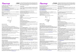
INSTALLAZIONE E USO
INSTALLATION AND USE
ZUSAMMENBAU
UND BETRIEB
Italiano
English
Deutsch
MEDIKA 427
le
gina
i
r
O
le O
nua ALIAN
a
M IT
in
Italiano English Deutsch
ATTENZIONE
Nel caso in cui quest'apparecchio contenga
refrigerante a base di idrocarburi si rimanda
alle linee di condotta elencate più sotto.
Se l'apparecchio contiene un refrigerante
infiammabile, è essenziale accertarsi che i
tubi del refrigerante non risultino danneggiati.
Poiché l'apparecchio contiene una sostanza
refrigerante infiammabile, è indispensabile
assicurarsi che non si verifichino danni alle
tubazioni del refrigerante.
Lo standard EN378 stabilisce che il locale in
cui verrà installato l'apparecchio deve avere
un volume di almeno 1m³ per ogni 8 g di
refrigerante a base di idrocarburi utilizzato
negli apparecchi, in modo da prevenire la
formazione di miscele infiammabili di gas
ed aria nel locale in cui è collocato
l'apparecchio in caso di perdite al circuito
del refrigerante. La quantità di refrigerante
utilizzata nel vostro apparecchio è indicata
sulla targhetta dei dati tecnici.
ATTENZIONE:
evitare l'ostruzione delle aperture per la
ventilazione sull'involucro dell'apparecchio
o sulla struttura interna
ATTENZIONE:
non utilizzare attrezzature meccaniche o mezzi per accelerare il processo di sbrinamento
diversi da quelli raccomandati dal fabbricante.
ATTENZIONE:
non provocare danni al sistema del refrigerante.
ATTENZIONE:
non utilizzare apparecchiature elettriche all'interno dello scomparto frigorifero, a meno che
siano di tipo omologato dal fabbricante.
ATTENZIONE:
evitare di esporre l'apparecchio alla pioggia.
ATTENZIONE:
questo apparecchio non è concepito per essere utilizzato da bambini o persone inabili, a meno
che siano adeguatamente sorvegliati da una persona responsabile che si assicuri che siano in
grado di utilizzare l'apparecchio senza pericoli. Sorvegliare i bambini piccoli in modo da
assicurarsi che non giochino con l'apparecchio.
ATTENZIONE:
Se il modello viene fornito munito di batteria tampone, inserire nel programma di manutenzione
la sostituzione della batteria ogni tre anni.
ATTENZIONE:
se viene inserita una chiavetta USB non compatibile, può verificarsi il reset del controllore.
Tenere sempre le chiavi in un luogo diverso e fuori dalla portata dei bambini.
Prima di sottoporre l'apparecchio ad operazioni di manutenzione o di pulizia, togliere la spina
dalla presa di corrente o staccare l'alimentazione elettrica.
In caso di danni al cavo di alimentazione, la sostituzione di quest'ultimo deve sempre essere
effettuata dal fabbricante, da un suo addetto alla manutenzione o da simile personale
qualificato onde evitare situazioni di pericolo.
2
PRIMA DELL'UTILIZZO
Prima di mettere in funzione il vostro nuovo apparecchio, si prega di leggere attentamente le
seguenti istruzioni dato che contengono informazioni importanti per quanto riguarda la
sicurezza, l'installazione, la messa in funzione e la manutenzione. Conservare le istruzioni per
riferimenti futuri.
Controllare l'apparecchio al suo ricevimento per assicurarsi che non sia stato danneggiato
durante il trasporto. Danni dovuti al trasporto devono essere segnalati al distributore locale
prima che l'apparecchio venga messo in funzione.
Rimuovere l'imballaggio.
Prima di pulire e utilizzare l'apparecchio, rimuovere la pellicola. Pulire l'interno dell'apparecchio
utilizzando acqua tiepida con un detergente delicate. Risciacquare ed asciugare con cura
(vedere istruzioni pulizia). Utilizzare un panno morbido.
Se durante il trasporto, l'apparecchio è stato lasciato in posizione orizzontale, o se è stato
conservato in un ambiente freddo (più freddo di +5°C), è necessario sistemarlo e metterlo in
posizione verticale per almeno un'ora prima di accenderlo. Attenzione: se l'apparecchio deve
essere messo in posizione orizzontale, la porta deve restare sulla parte superiore e
l'apparecchio deve essere imballato con il suo imballaggio originario.
REGISTRAZIONE DELLA TEMPERATURE REALE
Alcuni modelli sono dotati di contenitori di riferimento
per la registrazione della temperatura reale.
Se l'apparecchio è dotato di contenitore per la registrazione
della temperatura reale, è importante preparare il contenitore
prima dell'utilizzo.
1.Il contenitore è posizionato come
mostrato sopra (fig. 1) e sotto (fig. 2)
2.Rimuovere il contenitore e riempirlo con una soluzione
di 100 ml di acqua e alcol in proporzione 1:1 (se di solito
utilizzate altri prodotti, utilizzate quelli)
3.Posizionare il contenitore sul retro del frigorifero ed
inserire il sensore nell'acqua. Assicuratevi che tutta la parte
metallica del sensore venga coperta dall'acqua.
N.B.: Il mix nel contenitore deve essere controllato e
rabboccato regolarmente.
INSTALLAZIONE ED AVVIO
Posizionamento
Per motivi di sicurezza ed operazionali, l'apparecchio non deve essere esposto alla pioggia.
L'apparecchio deve essere posizionato su una superficie piana, in un luogo asciutto e ben
ventilato (max. 70% umidità). Mai posizionare l'apparecchio vicino a fonti di calore ed evitare
l'esposizione solare diretta. La superficie su cui viene posizionato l'apparecchio deve essere
piana. Non collocare su telai o simili.
L'apparecchio può essere installato come unità indipendente vicino ad una parete oppure a
lato di altri dispositivi
3
Italiano English Deutsch
La formazione di brina sulle parti superiori e sulla parete interna dell'evaporatore è un
fenomeno naturale, e pertanto si raccomanda di sbrinare l'apparecchio durante le normali
operazioni di pulizia e di manutenzione.
Questo dispositivo è destinato ad essere utilizzato esclusivamente per prodotti medicali .
SPOSTARE L'UNITÀ
Sbloccare tutte le ruote. Prima di spostare l'unità, assicurarsi di aver
chiuso la porta. Quando si sposta l'unità, assicurarsi di aver sempre
la porta a vetro di fronte e tenerlo saldamente su ogni lato .
VENTILAZIONE
Le aperture per la ventilazione devono essere tenute pulite e
libere da ostruzioni. Le immagini di seguito mostrano lo spazio
necessario per garantire la circolazione dell'aria richiesta
(Minimo 150 mm Sopra) fig 4
Italiano English Deutsch
LIVELLAMENTO DELL'APPARECCHIO
E' importante che l'apparecchio sia in piano.
Se l'apparecchio è posizionato su una superficie
morbida, es. Pedane oppure su un tappeto, è necessario
controllare che l'apparecchio sia ancora in piano dato che
dopo un po’ di tempo la superficie potrebbe cedere sotto il
peso dell'apparecchio.
Alcuni modelli hanno i piedini regolabili. (Vedere fig 5)
LATO SU LATO
Nelle sistemazioni "lato su lato", devono essere garantiti
almeno 25 mm di spazio tra ogni unità e su ogni lato delle cabine per assicurarsi che le porte si
possano aprire liberamente
ALLESTIMENTO INTERNO
CASSETTI
I cassetti sono riposizionabili. Per rimuovere i cassetti, la porta deve essere aperta almeno a
90°.
1.Rimuovere il cassetto (Vedere fig 7)
2.Rimuovere e riposizionare le staffe (Vedere fig 8) nella posizione desiderata.
4
INSTALLAZIONE DEL CONTROLLO DI VENTILAZIONE
Chiudure le due sicure di ventilazione posizionate sul retro
dell'apparecchio per assicurare un'adeguata circolazione
dell'aria (Vedere fig. 9)
MONTAGGIO DEL SISTEMA DIVISORIO
1. Il binario con il doppio nastro adesivo va montato
all'interno della parte posteriore e nella parte frontale del
cassetto
2. Sistemare il divisorio
3. Sistemare i divisori e farli scorrere
1
3
SISTEMAZIONE DEI DIVISORI
I punti di interruzione permettono lo stoccaggio di prodotti individuali.
Sistemare i divisori come di seguito.
(Vedere fig 10) Tagliare nel punto esatto e rimuovere
la parte in eccesso.
PORTA REVERSIBILE
1.Aprire la porta. Identificare ed allentare
le viti. Rimuovere il pannello inferiore
come mostrato. (Vedere 10.)
2. Rimuovere il blocco utilizzando un
cacciavite piatto. Poi rimuovere
l'alloggiamento della serratura.
5
Italiano English Deutsch
2
Italiano English Deutsch
3. Rimuovere il magnete (senso
antiorario) e riposizionarlo sul lato
opposto del telaio della porta
4. Chiudere la porta. Disporre
l'apparecchio sul proprio dorso.
5. Aprire il pannello superiore
6. Controllare quanto perno
della cerniera è visibile. Questa
lunghezza deve essere
mantenuta anche nella porta
invertita.
7. Svitare e rimuovere le cerniere
superiori ed inferiori svitandole in
senso antiorario.
8. Ruotare la porta di 180° come
mostrato
9. Spostare i perni sul lato opposto e
sistemare la porta avvitando i perni
della parte superiore ed inferiore.
Assicurarsi che venga mantenuta la
stessa distanza (vedere 6)
10. Sollevare l'apparecchio
in posizione verticale.
Assicurarsi di mantenere
saldamente l'apparecchio
mentre lo si sposta.
Allineare la porta regolando il
perno superiore ed assicurarsi
che la porta sia chiusa e
sistemata correttamente.
11.Rimontare la serratura ed il pannello inferiore.
Si prega di notare che i 2 perni nel pannello
inferiore devono essere sistemati correttamente
negli spazi dedicati (inclinare il pannello se
necessario e fissurlo utilizzando le 2 viti)
SISTEMA BATTERIA BACKUP AD AVVIO
Alcuni modelli vengono forniti con sistema di batteria backup.
1. Aprire la porta
2. Utilizzare una penna per accendere il sistema di batteria backup nel foro (fig. 11)
3. Quando l'apparecchio è in funzione, si accenderà una spia verde
ATTENZIONE!
Il sistema di batteria backup non alimenta di
corrente il sistema refrigerante.
Quando si avvia l'apparecchio per la prima volta,
è necessario accendere il sistema di batteria
backup.
6
ATTENZIONE! La batteria di backup dovrebbe essere cambiato ogni tre anni per garantire 48
ore di backup. Si prega di inserire questo cambiamento nel programma di manutenzione per
ogni tre anni.
SISTEMA BATTERIA BACKUP
Alcuni modelli sono forniti di sistema batteria backup. Il sistema fornisce al controllore e al
display, alimentazione in caso di mancanza alimentazione. Questo rende possibile supervisionare le temperature dell'apparecchio durante la mancanza di alimentazione.
Il sistema di batteria backup rende possibile supervisionare le temperature per 50 ore. Dopo la
mancanza di alimentazione e al primo riavvio della macchina, la batteria deve essere ricaricata. Per ricaricare al massimo la batteria, servono 10 giorni.
UTILIZZO – VISUALIZZAZIONE PRINCIPALE:
(1) Temperatura corrente all'interno dell'apparecchio
(misurata dalla sonda Tr3)
(2) Ora e data
(3) Icona ALARM. Lampeggia ad allarme. Resta
visibile dopo nessun allarme attivo fino a quando viene
disattivato manualmente
(4) Icona Logging. Visibile quando sta registrando. Non visibile se non è attiva la registrazione.
(5) Icona Memory. Accesa quando la memoria è piena al 90%. Lampeggia quando la memoria
è piena, e il controllore sta cancellando i vecchi dati registrati.
(6) Barra Memory. Mostra lo stato della memoria.
CHIAVI – VISUALIZZAZIONE PRINCIPALE:
SET: Entra nel Menu Set Point della temperatura
SERVICE: Entra nel Menu Service
DATA: Entra nel Menu Data Logging (Registrazione dati)
ALARM: Entra nel Menu Alarm
Come visualizzare e modificare la temperatura
Set Point:
1. Premere e rilasciare immediatamente il tasto SET: il display mostrerà il valore del Set Point.
2. Per modificare il valore premere il tasto SET, il Set Point inizierà a lampeggiare
3. Utilizzare il tasti UP e DOWN per modificare il valore.
4. Per memorizzare il nuovo valore Set Point premere nuovamente il tasto SET oppure
aspettare 30sec.
MENU SERVICE:
Dal menu principale premere il tasto SERVICE
per accedere al menu SERVICE.
Vedere l'immagine di seguito:
7
Italiano English Deutsch
UTILIZZO E FUNZIONAMENTO
AVVIO:
Quando l'apparecchio è connesso alla corrente elettrica, il display si avvierà automaticamente
Il messaggio iniziale visualizzato sul display mostrerà i diversi software installati sul controllore
dell'applicativo. Premere "enter" per tornare alla visualizzazione "start up".
Italiano English Deutsch
PROBES: Accede alle sonde, per vedere le
temperature misurate. In base al modello sono
disponibili 1-4 sonde.
PARAMETERS: Accede alle impostazioni dei
parametri. Si prega di considerare che le modifiche
dei parametri devono essere apportate solo da un
tecnico. Il codice per accedere ai parametric Pr2 è
impostato di standard 12.
SELF TEST: Accede al programma Self Test del controllore.
CLOCK: Accede al menu orologio, dove è possibile modificare data e ora.
PASSWORD: Accede al menu password, dove è possibile modificare la password.
LANGUAGE: Accede al menu linguaggio, dove è possibile cambiare la lingua.
COME IMPOSTARE L'ORARIO E LA DATA:
1. Accedere al menu SERVICE
2. Selezionare il sottomenu CLOCK
3. Premere il tasto ENTER.
4. Impostare il giorno utilizzando i tasti UP e DOWN.
5. Premere il tasto SET, per confermare e passare
all'impostazione dell'orario.
6. Utilizzare la stessa procedura per l'impostazione
della data.
7. Poi confermare la selezione utilizzando il tasto SET.
COME UTILIZZARE IL SELF TEST:
1. Accedere al menu SERVICE
2. Selezionare il sottomenu SELF TEST
3. Premere il tasto ENTER,
4. Se è richiesra la PASSWORD, inserire la password,
5. ALTRIMENTI si accede direttamente al menu SELF TEST.
6. Premere il tasto START
7. Poi premere i tasti per attivare i carichi corrispondenti:
a. Compressore b. Luce c. Ventola d. Allarme e. Buzzer
8. Il display mostra lo stato dell'input digitale (ON oppure OFF)
9. Aspettare 30s oppure premere il tasto BACK per tornare alla schermata precedente
COME CAMBIARE LA LINGUA:
1. Accedere al menu SERVICE
2. Selezionare il sottomenu LANGUAGE
3. Premere il tasto ENTER e si accede al menu
LANGUAGE.
4. Premere il tasto SET e poi utilizzare i tasti UP
e DOWN per selezionare la lingue e poi premere
il tasto SET per conferma.
8
COME ACCEDERE ALLA REGISTRAZIONE:
1. Accedere al menu DATA
2. Selezionare il sottomenu LOG
3. Premere il tasto ENTER e si accede al sottomenù
LOG.
4. Utilizzando i tasti UP e DOWN scegliere l'intervallo di
dati da visualizzare
5. Premere il tasto ENTER pee visualizzare i dati
selezionati.
ATTENZIONE: IL TASTO VIENE UTILIZZATO PER FERMARE ED AVVIARE LA REGISTRAZIONE
I DATI REGISTRATI AVRANNO QUESTO LAYOUT:
Dove TR3, EVP, TL1, TL2 = Valore delle sonde.
Con errore sonda oppure mancanza:
viene visualizzato il simbolo " - ".
Si prega di considerare che in base al modello
sono disponibili 1-4 sonde
ST: stato del controllore/carico
● - = in funzione, senza nessun carico attivo;
● D = sbrinamento in funzione
(se è disponibile lo sbrinamento automatico )
● C = compressore in funzione
Il valore registrato dal sensore EVP si riferisce ESCLUSIVAMENTE al sistema di
refrigerazione. Il valore non rispecchia quello della temperatura della medicina sugli scaffali o
nei cassetti. Quando si deve controllare la temperatura della medicina o di prodotti
immagazzinati, utilizzare solo i valori registrati da TL1 e Tr3.
COME ESPORTARE I DATI:
1. Accedere al menu EXPORT
2. Inserire la chiavetta USB fornita.
3. Selezionare ALARM o DATA, il controllore inizia a trasmettere dati alal chiavetta USB,
quando l'esportazione è terminate, viene visualizzato il messaggio: EXPORT - Copy
completed.
I dati esportati vengono esportati come file CSV (Comma Separated Values). Questi file possono essere utilizzati ad esempio in Excel per realizzare grafici.
IMPORTANTE: durante il download non rimuovere la chiavetta USB: questa azione potrebbe
danneggiare i dati e la chiavetta stessa.
ATTENZIONE: lasciare la chiavetta USB inserita solo per il tempo necessario all'esportazione
dei dati, poi rimuoverla.
ATTENZIONE: se viene inserita una chiavetta USB non compatibile, può verificarsi il reset del
controllore
9
Italiano English Deutsch
MENU DATA:
Dalla visualizzazione principale, premere il tasto
DATA e si accede al menu DATA. Vedere l'immagine
di seguito:
LOG: Entra nei dati registrati dal controllore.
EXPORT: Esporta i dati sulla chiavetta USB spedita
insieme all'apparecchio.
GRAPH: Accede ai grafici mostrando la temperature registrata delle ultime 24h (con un
intervallo di registrazione di 15min.)
COME ACCEDERE AL GRAFICO:
1. Accedere al menu DATA
2. Selezionare il sottomenu GRAPH
3. Premere il tasto ENTER e si accede al menu
GRAPH.
4. Utilizzando i tasti UP e DOWN scegliere la sonda
che deve essere visualizzata.
5. Premere il tasto HOME per tornare alla
schermata principale.
ATTENZIONE: quando il controllore viene spento,
il grafico viene cancellato.
Italiano English Deutsch
MENU ALLARME:
Se l'icona dell'allarme sta lampeggiando sul display
principale, è in corso un allarme.
Se viene visualizzata un'icona allarme ma non sta lampeggiando sul menu principale, si è
manifestato un allarme che è stato richiamato.
Una volta che il segnale di allarme viene rilevato, il buzzer può essere silenziato premendo
qualsiasi tasto.
Allarmi attivi:
1. Premere il tasto ALARM per accedere al menu
allarme.
2. Il menu allarme mostra l'allarme attivo con i
seguenti layout:
a. Prima colonna = codice allarme
b. Seconda colonna = descrizione allarme
3. Premere il tasto LOG per accedere a ACTIVE
ALARM LOG.
Questo menu contiene tutte le informazioni per
quanto riguarda gli allarmi attivi. Nella prima linea,
viene visualizzato il numero degli allarmi attivi.
4. E' possibile spostarsi tra gli allarmi con i
tasti UP e DOWN.
5. Premere il tasto LOG per accedere a ALARM LOG.
Questo menu contiene tutti gli allarmi memorizzati. Per ogni allarme vengono registrati il tempo
di inizio e la data e il tempo di fine e la data
“P1”
“P2”
Regolazione guasto sonda
Tr3
Uscita allarme ON; uscita compressore in accordo
con i parametri Con e CoF
Guasto sonda EVP
Uscita allarme ON; alter uscite invariate
10
“P4”
Guasto registrazione sonda
Tl1 failure
Uscita allarme ON; alter uscite invariate
Guasto registrazione sonda
Tl2
Uscita allarme ON; alter uscite invariate
“Ha1”
Allarme alta TR3
Uscita allarme ON; alter uscite invariate
“La1”
Allarme bassa TR3
Uscita allarme ON; alter uscite invariate
“Ha3”
Allarme alta temperatura
sonda Tl1
Uscita allarme ON; alter uscite invariate
“La3”
Allarme bassa temperatura
sonda Tl1
Uscita allarme ON; alter uscite invariate
“Ha4”
Allarme alta temperatura
sonda Tl2
Uscita allarme ON; alter uscite invariate
“La4”
Allarme bassa temperatura
sonda Tl2
Uscita allarme ON; alter uscite invariate
“dA”
Allarme porta aperta
“EA”
Allarme esterno
Uscita invariato.
“CA”
Allarme serio
Tutte le uscite OFF.
Compressore e ventilatori dipendono "rrd”
SBRINAMENTO, PULIZIA E MANUTENZIONE
SBRINAMENTO AUTOMATICO.
Il frigorifero viene sbrinato automaticamente. L'acqua residua dallo sbrinamento attraversa un
tubo e viene raccolta in una vasca sopra il compressore dove il calore generato dal
compressore causa la sua evaporazione. Il vassoio che raccoglie l'acqua residua, dovrebbe
essere pulito regolarmente.
PULIZIA E MANUTENZIONE
Prima della pulizia, scollegare dalla corrente elettrica e rimuovere tutti i raccordi allentati.
Si ha una migliore pulizia dell'apparecchio utilizzando acqua calda (max 65°C) con una piccola
quantità di detergente delicato profumato. Mai utilizzare detergenti che scrostano. Utilizzare un
panno soffice. Risciacquare con acqua pulita ed asciugare accuratamente. E' importante non
far entrare l'acqua all'interno del pannello di controllo.
Le guarnizioni intorno alla porta devono essere pulite regolarmente per prevenire la
decolorazione e prolungare la loro efficacia. Utilizzare acqua pulita. Dopo aver pulito le
guarnizioni, verificare che continuino ad aderire perfettamente.
11
Italiano English Deutsch
“P3”
Italiano English Deutsch
Si consiglia di pulire il filo ed i condensatori sul retro dell'apparecchio.
La griglia di ventilazione, il condensatore, il compartimento compressore, devono essere
mantenuti puliti e liberi da polvere e sporcizia. Pulire con un aspirapolvere regolarmente.
Rimuovere il pannello inferiore sotto la porta svitando le due viti. Fare lo stesso sul retro (vedi
fig. 12) .
N.B.: Se l'apparecchio non viene utilizzando per un lungo periodo di tempo, spegnerlo,
staccare il cavo dell'alimentazione, pulire l'interno e lasciare la porta aperta per permettere la
circolazione dell'aria e prevenire odori.
12
BEFORE USE
Before operating your new appliance, please read the following instructions carefully as they
contain important information on safety, installation, operation and maintenance. Keep the
instructions for future reference.
On receipt, check to ensure that the appliance has not been damaged during transport.
Transport damage should be reported to the local distributor before the appliance is put to use.
REMOVE THE PACKAGING.
The foil on the shelves must be removed before cleaning and using the unit.
13
Italiano English Deutsch
WARNING
In case this appliance contains hydrocarbon
refrigerant please refer to guidelines listed below.
As the appliance contains a flammable refrigerant,
it is essential to ensure that the refrigerant pipes
are not damaged.
Standard EN378 specifies that the room in which
you install your appliance must have a volume of
1m³ per 8 g of hydrocarbon refrigerant used in
the appliances. This is to avoid the formation of
flammable gas/air mixtures in the room where
the appliance is located in the event of a leak
in the refrigerant circuit. The quantity of the
refrigerant used in your appliance is indicated
on the rating plate.
WARNING: Keep ventilation openings in
the appliance's cabinet or in the built-in
structure clear of obstruction
WARNING: Do not use other mechanical
devices or other means to accelerate the
defrosting process than those recommended
by the manufacturer
WARNING: Do not damage the refrigerant system
WARNING: Do not use electrical appliances
inside the refrigerated storage compartment,
unless they are of a type recommended by the
manufacturer
WARNING: Do not expose the appliance to rain
WARNING: This appliance is not intended for use by young children or infirm persons unless
they have been adequately supervised by a responsible person to ensure that they can use the
appliance safely. Young children should be supervised to ensure that they do not play with the
appliance
- Always keep the keys in a separate place and out of reach of children
- Before servicing or cleaning the appliance, unplug the appliance from the mains or disconnect
the electrical power supply
- If the supply cord is damaged, it must be replaced by the manufacturer, its service agent, or
similarly qualified persons in order to avoid a hazard
- Frost formation on the inside wall and upper parts is a natural phenomenon. Therefore, the
appliance should be defrosted during normal cleaning or maintenance
- Please note that changes to the appliance construction will cancel all warranty and product
liability
- This device is intended to be used exclusively for medical products
Clean the inside of the cabinet using warm water with a mild detergent. Rinse with clean water
and dry thoroughly (see cleaning instructions). Use a soft cloth.
If during transport the appliance has been laid down, or if it has been stored in cold surroundings (colder than +5°C), it must be allowed to stabilise in an upright position for at least
an hour before being switched on. Note: If the appliance is to be laid down, the door must face
upwards and the appliance must be enclosed in the original packaging.
Italiano English Deutsch
PLACEMENT
For safety and operational reasons, the appliance must not be exposed to rain.
The appliance should be placed on a level surface in a dry, well ventilated room (max. 70%
relative air humidity). Never place the appliance close to sources of heat and avoid placing it in
direct sunlight. The surface on which the appliance is to be placed
must be level. Do not place on a frame or similar.
The appliance can be installed as a free-standing unit against a
wall or side-by-side with other appliances
MOVING THE UNIT
Unlock castors on all wheels.
Before moving the unit, ensure to close and lock the door.
When moving the unit, make sure to always face the glass
door and hold firmly on the each side of the glassdoor as
showed above.
Fig. 1
VENTILATION
Keep ventilation openings in the appliance enclosure or
in the built-in structure, clear of obstruction. The figures
below illustrate the clearance necessary to achieve the
required air circulation.
(Minimum 150 mm above) fig 2
LEVELLING THE APPLIANCE
It is important that the appliance is absolutely level.
If the appliance is placed on a soft surface, e.g. floorboards
or a carpet you must recheck whether the appliance is still
level after a period of time as the underlying surface may
yield under the weight of the appliance.
Some models have adjustment feets. (See fig 3)
SIDE BY SIDE
In side-by-side arrangements there must be
at least 25 mm between each unit on each
side of the cabinets, to ensure the doors
can be opened freely
Fig. 2
INTERIOR FITTING
Drawers
The drawers can be repositioned.
To remove the drawers the door must be
opened at least 90°.
Fig. 3
1.Remove drawer (See fig 5)
2.Remove and replace drawer brackets (See fig 6) in desired position.
14
Fig. 6
Fig. 5
Mounting of dividing system in the drawers
1. The Rail Holder with double adhesive tape is mounted
inside the rear and front of the drawer .
2. Put in the rails
3. Snap on the dividers and slide it
Fig. 7
1
3
2
ADJUSTMENT OF DIVIDING PARTS
Integrated breakpoints allows storage of individual
products. Adjust the dividing part as follows.
(See fig 8) Cut into the appropriate seam
and break of the excess part.
REVERSIBLE DOOR
Fig. 8
1. Open door. Locate and untighten screws.
Remove the foot panel as shown.(See 10.)
2. Remove the lock fin using a
flat-headed screwdriver. Then
remove the lock housing
15
Italiano English Deutsch
INSTALLATION OF VENTILATIONGUARD
Close the two ventilationguards placed on the rear of the
appliance, to ensure sufficient air circulation (See fig. 7)
Italiano English Deutsch
3. Remove magnet (counter-clockwise)
and place it in the opposing location on
the door frame.
5. Open the top panel.
4. Close the door.
Lay the appliance
on its back.
6. Make sure how much of the
hinge pin is visible. This distance
must be maintained for the
reversed door
7. Untighten and remove top
and bottom hinge pins by
turning them counter-clockwise.
9. Move hinge pins to the opposite
site and fit the door by tightening
the hinge pins to top and bottom
of door. Ensure the distance
(see 6.) is strictly maintained.
10.Raise the appliance into upright
position. Ensure to hold firmly onto
the door while moving the appliance.
Align the door by adjusting the top
hinge pin and ensure the door is
securely locked and in place.
BATTERY BACKUP SYSTEM AT START-UP
NOTE!
The battery backup system does not supply the
cooling system with power.
When starting up the appliance for the first time
it is necessary to switch on the battery backup system.
1. Open the door
2. Use a pen to switch on the battery backup system in
the hole shown on fig. 9
3. The switch will light green when the unit is powered
16
8. Rotate door 180° as shown
11. Remount lock and foot panel.
Please note: The 2 pins on the foot panel
must be fitted correctly in the dedicated
spaces (tilt the panel if needed and fix the
panel using the 2 screws).
Fig.10
Fig.11
OPERATION AND FUNCTION
START UP:
When the appliance is connected to the power supply, the keyboard will automatically start up.
The start up view on the keyboard will show the different
software installed on the controller of the appliance.
Press enter to return from the start up view.
OPERATION – MAIN VIEW:
(1) Current temperature inside appliance (measured
by the TR3 probe)
(2) Time and date
(3) ALARM icon. Flashing by alarm. Remains visible after no active alarm until manually dismissed
(4) Logging icon. Visible when logging. Not visible
if no active logging.
(5) Memory icon. On when the memory is 90% full.
Flashing when the memory is full, and the controller
is deleting the oldest logging data.
(6) Memory bar. Shows the status of the memory.
KEYS – MAIN VIEW:
SET: Enter the Set Point menu of the temperature
SERVICE: Enter the Service menu
DATA: Enter the Data Logging menu
ALARM: Enter the Alarm menu
How to see and modify the temperature Set Point:
1. Push and immediately release the SET key: the display will show the Set Point value.
2. To modify the value push the SET key, the Set
Point starts flashing.
3. Use the UP and DOWN keys to modify the value.
4. To memorize the new Set Point value push the SET
key again or wait 30sec.
17
Italiano English Deutsch
REAL TEMPERATURE LOGGING
Some models are equipped with reference containers
to make a real temperature logging.
If the unit is equipped with containers for real
temperature logging. It is important to prepare the
containers before use.
1.The containers is placed like shown in top fig.10 and
bottom fig.11
2.Remove the containers and fill it with 100ml with a
mixture of water and alcohol in ration 1:1 (if you are use
to use other products for reference containers you may
use this).
3.Place the containers back is the refrigerator and put
the sensor in the water. Make sure that all of the metal
on the sensor is covered in water.
OBS: The mixture in the containers shall be checked
and refilled on a regular basis.
SERVICE MENU:
From the main view push the SERVICE key and
the SERVICE menu is entered.
See below picture:
Italiano English Deutsch
PROBES: Enter the probes, to see the measured
temperatures. 1-4 probes is availa ble depending
on model.
PARAMETERS: Enter the setting of the parameters. Please note that changes made to the
parameters should only be made by a technician. The code to enter the Pr2 parameters is
standard set to 12.
SELF TEST: Enter the Self Test program of the controller.
CLOCK: Enter clock menu, where it is possible to change date and time.
PASSWORD: Enter the password menu, where it
is possible to change the password.
LANGUAGE: Enter the language menu, where it is
possible to change language.
HOW TO SET TIME AND DATE:
1. Enter the SERVICE menu
2. Select CLOCK sub-menu
3. Push the ENTER key.
4. Set the day by means of the UP and DOWN keys.
5. Push the SET key, to confirm and pass to the setting of time.
6. Use the same procedure as for the date.
7. Then confirm the selection by means of the SET key
HOW TO USE THE SELF TEST:
1. Enter the SERVICE menu
2. Select SELF TEST sub-menu
3. Push the ENTER key,
4. If PASSWORD is required, insert the password,
5. OTHERWISE the SELF TEST menu is entered directly.
6. Push the START key
7. Then push the keys to activate the correspondent loads:
a. Compressor b. Light c. Fan d. Alarm e. Buzzer
8. The display shows the status of the digital input (ON or OFF)
9. Wait 30s or push the BACK key to come back to
the previous screen.
HOW TO CHANGE LANGUAGE:
1. Enter the SERVICE menu
2. Select LANGUAGE sub-menu
3. Push the ENTER key and the LANGUAGE menu
is entered.
4. Push the SET key and then use the UP and DOWN
keys to select the language and then the SET key to
confirm it.
18
HOW TO ENTER THE LOG:
1. Enter the DATA menu
2. Select LOG sub-menu
3. Push the ENTER key and the LOG menu is entered.
4. By UP and DOWN keys chose the data interval to
display
5. Push the ENTER key to display the selected data.
NOTE: THE KEY: IS USED TO STOP AND START
LOGGING
Logged data will have this layout:
Where TR3, EVP, TL1, TL2 = Value of probes.
With probe failure or absence:" - " symbol is displayed.
Please note that 1-4 probes are available depending
on model.
ST: status of the controller/load
- = operating, without any load activated;
D = defrost running (if automatic defrost is available)
C = compressor working
HOW TO EXPORT DATA:
1. Enter the EXPORT menu
2. Insert the USB pen drive.
3. Select ALARM or DATA, the controller starts sending data to the pen drive, when
the export is finished the message: EXPORT - Copy completed is displayed.
The exported data will be exported as a CSV-file (Comma Separated Values). This file can be
used in ex. Excel for making graphs.
IMPORTANT: during the download don't remove the USB pen drive: this action could damage
the data files and USB pen drive itself.
WARNING: leave the USB pen inserted only for the time necessary to export data then
remove.
WARNING: if a not compatible USB pen drive is used it can cause a reset of the controller
HOW TO ENTER THE GRAPH:
1. Enter the DATA menu
2. Select GRAPH sub-menu
3. Push the ENTER key and the GRAPH menu is
entered.
4. By UP and DOWN keys chose the probe that has
to be displayed.
5. Push the HOME key to get back to the main view.
19
Italiano English Deutsch
DATA MENU:
From the main view push the DATA key and the DATA
menu is entered.
See below picture:
LOG: Enter the data logged by the controller.
EXPORT: Export the data to an USB pen drive delivered
with the appliance.
GRAPH: Enter the graph showing the temperature logged the last 24h (with a logging inter-val
of 15min.)
Italiano English Deutsch
NOTE: A graph is erased when the controller is
switched off.
ALARM MENU:
If the alarm icon is flashing on the main display, an
alarm is occurring.
If the alarm icon is displayed but not flashing on the
main display, an alarm is occurred and recovered.
Once the alarm signal is detected the buzzer can be silenced by pressing any key.
Active alarms:
1. Push the ALARM key to enter the alarm menu.
2. The alarm menu displays the active alarm with the following layout:
a. First column = alarm code
b. Second column = alarm description
3. Push the LOG button to enter the ACTIVE
ALARM LOG.
This menu contains all the information concerning
the active alarms. In the first line, it is displayed how
many alarms are happening.
4. It's possible to move through the alarms by the
UP and DOWN keys.
5. Push the LOG button to enter the ALARM LOG.
This menu contains all the memorized alarms.
For each alarm the starting time and date and the
finish time and date are recorded.
Alarm output ON; compressor output according
to parameters Con and CoF
“P1”
Regulating probe tr3 failure
“P2”
EVP probe failure
“P3”
Logging probe Tl1 failure
Alarm output ON; Other outputs unchanged
“P4”
Logging probe Tl2 failure
Alarm output ON; Other outputs unchanged
TR3 High alarm
Alarm output ON; Other outputs unchanged
“Ha1”
Alarm output ON; Other outputs unchanged
20
Alarm output ON; Other outputs unchanged
Tr3 low alarm
“Ha3”
High temperature alarm probe Tl1
Alarm output ON; Other outputs unchanged
“La3”
Low temperature alarm probe Tl1
Alarm output ON; Other outputs unchanged
“Ha4”
High temperature alarm probe Tl2
Alarm output ON; Other outputs unchanged
“La4”
Low temperature alarm probe Tl2
Alarm output ON; Other outputs unchanged
“dA”
Door open alarm
“EA”
External alarm
“CA”
Compressor and fans depend on “rrd”
Output unchanged
Serious alarm
All outputs OFF
BATTERY BACKUP SYSTEM
Some models are equipped with a battery back up system. The system supplies the controller
and keyboard with power at power failure. This makes it possible to supervise the temperatures
in the unit during the power failure. The battery backup system makes it possible to supervise
the temperatures for 50 hours. After a power failure and at the first start up the battery needs to
be recharged. To regain the full capacity the battery will be reloading for 10 days
AUTOMATIC DEFROSTING.
The refrigerator is defrosted automatically. Defrost water runs through a pipe and is collected in
a tray above the compressor where the heat generated by the compressor causes it to
evaporate. The defrost water tray should be cleaned at intervals.
CLEANING AND MAINTENANCE
Before cleaning, disconnect the power supply and remove all loose fittings.
The appliance is best cleaned using warm water (max. 65°C) with a little mild, perfume-free
detergent. Never use cleaning agents that scour.
Use a soft cloth. Rinse with clean water and dry thoroughly. It is important to prevent water
from entering the control panel.
The sealing strips around the door must be cleaned regularly to prevent discolouration and
prolong service life. Use clean water. After cleaning the sealing strip, check that it continues to
provide a tight seal. It is recommended that the wire and tubular condensers on the rear of the
appliance be cleaned.
The ventilation grille, the condenser, the compressor and the compressor compartment must
also be kept free of dust and dirt. Clean it with a vacuum cleaner regularly.
Remove the lower panel from beneath the door by loosening the two screws. Do the same on
the back (see fig. 12)
21
Italiano English Deutsch
“La1”
Italiano English Deutsch
OBS: If the appliance is not to be used for any
length of time, switch it off, disconnect the
power supply, empty it, clean the inside and
leave the door open to allow air circulation
and prevent smells.
22
VOR GEBRAUCH BITTE BEACHTEN
Vor Inbetriebnahme ihres neuen Gerätes lesen Sie bitte die Bedienungsanleitung sorgfältig
durch. Sie enthält wichtige Informationen zu Sicherheit, Aufstellung, Betrieb und Wartung..
Bewahren Sie die Anleitung zum späteren Nachschlagen auf. Nach Erhalt überprüfen Sie ihr
Gerät auf Transportschäden. Transportschäden sind dem Händler vor Ort vor Inbetriebnahme
zu melden. Entfernen sie die Verpackung. Die Folie auf den Einlegeböden muss vor
Inbetriebnahme bzw. Reinigung entfernt werden. Reinigen Sie das Innere des Gerätes mit
warmen Wasser und einem milden Reinigungsmittel.
23
Italiano English Deutsch
WARNUNG
Falls dieses Gerät Kohlenwasserstoff-Kältemittel
enthält, sehen Sie bitte die untenstehenden Richtlinien.
Da ein brennbares Gas als Kältemittel
in diesem Gerät dient, ist es wichtig
icherzustellen, dass kein Teil des
Kühlkreislaufs oder der Röhren beschädigt ist.
Der Standard EN378 spezifiziert, dass der
Raum, in dem das Gerät installiert wird, ein
Volumen von 1m³ pro 8 g Kohlenwasser
stoff-Kältemittel, das im Gerät verwendet
ist, haben soll. Dies ist zu beachten, um
die Bildung von leicht entzündlichen
Gasgemischen in dem Raum, wo das
Gerät installiert ist, zu vermeiden, falls
eine Undichtigkeit des Kuhlkreislaufs
entsteht. Die Menge von Kältemittel im
Gerät ist auf dem Typenschild angegeben.
WARNUNG: Decken Sie die
Lüftungsöffnungen im Kabinett am
Gerätes oder am Einbaumodul nicht ab.
WARNUNG: Verwenden Sie keine anderen
mechanischen Geräte oder Hilfsmittel um
den Entfrostungsprozess zu beschleunigen,
als die Geräte, die vom Hersteller empfohlen sind.
WARNUNG: Beschädigen Sie nicht den Kühlkreislauf.
WARNUNG: Verwenden Sie keine elektrischen
Geräte im Gerät, es sei denn, dass die Geräte
vom Hersteller empfohlen sind.
WARNUNG: Das Gerät nicht dem Regen aussetzen.
WARNUNG: Das Gerät ist nicht für den Gebrauch durch kleine Kinder bestimmt, es sei denn,
dass es ausreichend von einer verantwortlichen Person überprüft ist, dass sie das Gerät
vertretbar verwenden können. Kleine Kinder müssen beaufsichtigt werden, um sicherzustellen,
dass sie nicht mit dem Gerät spielen. Der Schlüssel ist an einer separaten Stelle und
unzugänglich für Kinder aufzubewahren.
Vor Reparatur oder Reinigung des Gerätes den Netzstecker von der Steckdose ziehen.
Wenn die Anschlussleitung beschädigt ist, muss sie nur vom Hersteller, dem Serviceagent des
Herstellers oder einem anderen Fachmann ausgewechselt werden, um Gefahr zu vermeiden.
Bildung von Reif auf der inneren Verdampferplatte und den obersten Teile ist normal. In
Verbindung mit Reinigung oder Wartung muss das Gerät deshalb entfrostet werden.
Beachten Sie bitte, dass Änderungen der Konstruktion dieses Gerätes zur Folge haben, dass
die Garantie und Produktenhaftung erlöschen.
Dieses Gerät soll ausschließlich für medizinische Produkte verwendet werden
Mit klarem Wasser nachspülen und sorgfältig trocknen (siehe Pflegehinweise). Verwenden Sie
ein weiches Tuch. Wurde das Gerät liegend transportiert oder in kalter Umgebung gelagert
(kälter als +5 ° C ) muss das Gerät in aufrechter Position für mindestens 1 Stunde stabilisiert
werden bevor es eingeschaltet wird. Hinweis: Wenn Sie das Gerät hinlegen muss die Tür nach
oben zeigen und das Gerät muss in der Originalverpackung verbleiben.
Italiano English Deutsch
REFERENZTEMPERATURMESSUNG
Einige Modelle sind mit Referenzbehältern ausgestattet um
die tatsächliche Temperatur zu messen.
Es ist wichtig die Referenzbehältern vor Benutzung
entsprechend vorzubereiten.
1.Die Behälter befinden sich oben und unten, (siehe Bilder 1+2)
2.Entfernen Sie die Behälter und füllen Sie diese mit
einem Gemisch 1:1 aus Wasser und Alkohol. Sie können
auch andere Behälter als Referenz benutzen.
3.Setzen Sie die Referenzbehälter wieder ein und stecken
Sie den Temperaturfühler in das Wasser. Stellen Sie sicher
dass der gesamte Fühler vom Wasser bedeckt wird.
Aufstellung und Inbetriebnahme
Standort
Aus Sicherheits- und Betriebsgründen darf das Gerät nicht
Regen ausgesetzt werden. Das Gerät muss auf einem ebenen,
festen trockenem Palz in einem gut belüftetem Raum stehen
(max. 70%.relative Luft-feuchtigkeit).
Niemals das Gerät dicht an Wärmequellen aufstellen oder direkter Sonneneinstrahlung
aussetzen.. Die Oberfläche auf die das Gerät gestellt wird muss eben und fest sein.
Verwenden Sie keinen Rahmen oder ähnliches. Das Gerät kann als freistehendes Gerät oder
Seite an Seite mit anderen Geräten aufgestellt werden.
BELÜFTUNG
Beachten Sie bei der Aufstellung die angegebenen
Mindestabstände für eine sichere und ausreichende
Belüftung des Geräte. Halten Sie Lüftungsöffnungen
unbedingt offen um die erforderliche Luftzirkulation
zu gewährleisten. Die untere Abbildung zeigt die
notwendigen mindestabstände
(oberhalb mindestens 150 mm ) Abb.1
Ausrichten des Gerätes
Es ist wichtig dass das Gerät absolut eben steht.
Steht das Gerät auf einem weichen Untergrund,
z,B. Dielen oder Teppich, ist es am besten den ebenen
Stand des Gerätes nach gewisser Zeit zu kontrollieren,
weil der Untergrund unter dem Gewicht
des Gerätes nachgeben kann.
Einige Modelle haben einstellbare Füße.
(siehe Abb.5)
24
Installation des
Lüftungsschutzes
Schließen Sie die beiden Abstandshalter an der Rückseite des Gerätes um eine ausreichende
Luftzirkulation sicherzustellen. (Siehe Abb.9)
Batterie-Backup-System beim Start (BBU)
Einige Modelle sind mit einem BBU-System ausgerüstet
Hinweis!
Das BBU-System versorgt nicht das Kühl-system mit
Strom, sondern nur die Anzeige.
Wenn das Gerät das erste Mal einge- schaltet wird
ist es erforderlich das BBU- System einzuschalten.
Zur Vermeidung von Entladung ist die Batterie
während Transport und Lagerung abgeschaltet.
1. Öffnen Sie die Tür
2. Benutzen Sie einen Stift um durch das
Loch das BBU-System einzuschalten
3. Der Schalter leuchtet wenn er einge schaltet ist.
Betrieb und Funktion
Inbetriebnahme:
Sobald das Gerät an die Stromversorgung angeschlossen wird startet das Gerät automatisch.
Die Anzeige zeigt die verschiedenen installierten Software an. Drücken Sie ENTER um zur
Startseite zu gelangen.
Betrieb-Hauptansicht:
(1) Temperatur im Gerät (gemessen von Fühler TR3)
(2) Zeit und Datum
Hauptbildschirm
25
Italiano English Deutsch
INNENAUSBAU
SCHUBLADEN
Die Schubladen können neu positioniert werden. Um die Schubladen zu entfernen muss die
Tür mindestens 90 ° geöffnet werden.
1.Entferne die Schublade (siehe Bild 7)
2.Montieren Sie die Schubladenhalter in die gewünschte Position. (siehe Bild 8)
(3) ALARM Symbol. Blinkt bei Alarm. Generell an wenn ein Alarm vorhanden war, aber z.Z.
nicht mehr aktiv ist..
(4) Protokollierungssymbol: Aus=keine Protokollierung, Ein=Protokollierung.
(5) Speichersymbol :
Ein=Speicher zu 90% gefüllt.
Blinkt=Speicher voll und die ältesten Daten gehen verloren.
(6) Speicheranzeige:
Zeigt den Status des Speichers.
Italiano English Deutsch
TASTEN – HAUPTMENUE:
SET: öffnet das Temperatur- Sollwert-Menue
SERVICE: öffnet das Service-Menue
DATA: öffnet das Daten-Protokollierungs-Menue
ALARM: öffnet das Alarm-Menue
Anzeige und Änderung des Temperatur-Sollwertes:
1. kurz die Set-Taste drücken, Anzeige zeigt die
Sollwerte.
2. Sollwert ändern, Set-Taste drücken bis Sollwert
blinkt.
3. benutzen Sie die UP und DOWN Tasten um
den Sollwert zu ändern.
4. neuen Sollwert speichern erneut Set-Taste
drücken oder 30s warten.
Service Menue:
Im Hauptmenue SERVICE-Taste drücken und
das Servicemenue wird angezeigt. Siehe Bild unten.
Mit den Tasten UP und DOWN Menuepunkt wählen
und mit Enter aufrufen
Fühler: die gemessenen Temperaturen werden
angezeigt. Bis zu 4 Fühler sind verfügbar, abhängig vom Modell.
Parameter: Zeigt die Einstellung der Parameter des jeweiligen ausgewählten Fühlers. Bitte
beachten Sie, dass Einstellungen an den Parametern nur von einem Techniker vorgenommen
werden sollten. Das Passwort für Pr2 Parametere ingabe ist standardmässig auf 12 gesetzt.
Selbsttest: Öffnet das Selbsttestprogramm. Passworteingabe erforderlich.
Uhr: Öffnet das Zeitmenue. Hier ist es möglich Datum und Uhrzeit zu ändern. Passwort: Öffnet
das Passwortänderungsmenue.
Sprache: Öffnet das Sprachen-Auswahlmenue.
Ändern von Zeit und Datum:
1. Rufe das Servicemenue auf.
2. Wähle das Clock-Menue aus.
3. Drücke die Enter-Tanste.
4. Wähle mit den UP und Down Tasten die zu
ändernden Daten und drücke SET. Die marki erte
Stelle blinkt und kann nun mit den UP und Down
Tasten verändert werden,
5. Zur Bestätigung SET Taste drücken. Der
Curser springt weiter zur nächsten Zeile.
6. Benutze die gleiche Reihenfolge zur
Änderung der anderen Daten.
7. Verlassen sie das Clock-Menue mit
Back oder Home.
26
Änderung der Sprache:
1. Wähle das SERVICE Menue
2. Wähle das Sprach-Untermenue aus.
3. Drücke die ENTER Taste.
4. Drücke die SET Taste und benutze die
UP und Down Taste für die Sprachauswahl.
Zur Bestätigung SET drücken.
Daten Menue:
In der Hauptansicht Data-Taste drücken
und das Datenmenue wird angezeigt.
Siehe Bild unten.
Speichern: Anzeige der vom Controller
gespeicherten Daten.
Export: Speichert die Daten auf ein USB-Stick.
Diagramm: Graphische Temperaturanzeige
der letzten 24 Std. (Speicherintervall 15min).
Anzeige der Daten im LOG-Menue:
1. Wähle Daten-Menue in der Hauptansicht
2. Wähle mit UP und Down Tasten
LOG-Untermenue
3. Drücke ENTER und das LOG-Menue wird
geöffnet.
4. Mit UP und DOWN Taste Datenintervall
auswählen.
5. Drücke ENTER und die ausgewählten Daten
werden gezeigt.
PS: Mit der
Taste Starten bzw. Stoppen Sie
das Speichern. (Taste 3sec drücken)
Anzeige der Daten:
TR3, EVP, TL1, TL2 = Nummer der Fühler.
Bei Fühlerfehler oder kein Fühler vorhanden
wird " - " angezeigt. Je nach Modell sind bis zu 4 Fühler möglich.
ST: Zustand des Kontrollers/Last
● - = Betrieb, keine Belastung eingeschaltet.
D = Abtauung läuft (wenn automatische Enteisung verfügbar ist).
C = Kompressor arbeitet.
27
Italiano English Deutsch
Benutzung des Selbsttest-Menues:
1. Wähle das SERVICE Menue
2. Wähle das Selbstest-Untermenue aus.
3. Drücke die ENTER Taste.
4. Falls erforderlich Passwort eingeben
(standardmäßig auf 12 gesetzt) und Enter
und danach Start drücken.
6. Drücke die START Taste.
7. Drücken Sie für den Test die
entsprechende Taste.
a. Kompressor b. Licht
c. Ventilator d. Alarm e.Summer
8. In der Anzeige ist der Status vom Digitaleingang (Türschalter) zu sehen. (EIN/AUS)
9. Drücken Sie die Back Taste oder warten Sie 30s um zum vorherigen Menue zu gelangen.
Italiano English Deutsch
So exportieren Sie Daten:
1. Wähle EXPORT-Menue
2. USB Stick einstecken. (Von Vestfrost geliefert).
3. Drücke ALARM oder DATA, der Kontroller sendet die Daten zum USB Stick.
Wenn die Übertragung abgeschlossen ist wird EXPORT -Kopieren ausgeführt angezeigt.
Die übertragenden Daten werden im CSV-Format (Comma Separated Values) gespeichert.
Dieses Format kann z.B. zur weiteren graphischen Darstellung in Excel benutzt werden.
Warnung: während der Übertragung nicht den
USB Stick ziehen. Dies kann Schäden an den
Daten und dem USB Stick verursachen.
Warnung: lassen Sie den USB Stick nur für die
Datenübertragung eingesteckt. Danach bitte ziehen.
Warnung: wenn ein nicht kompatibler USB Stick
verwendet wird kann dies zu einem Reset des
Kontrollers führen.
Anzeige des Graphen:
1. Wähle Daten-Menue in der Hauptansicht
2. Wähle DIAGRAMM-Untermenue
3. Drücke ENTER und der Graph wird dargestellt.
4. Mit der UP and DOWN Taste wählen sie den
Fühler zur Anzeige aus.
5. Drücken Sie HOME um ins Hauptmenue
zurückzukehren.
PS: Das Diagramm wird bei Ausschalten gelöscht,
alle Daten sind aber abgespeichert.
Alarm Menue
Wenn das Alarm-Symbol im Hauptmenue blinkt,
ist ein Alarm aktiv.
Wenn das Alarm-Symbol nicht blinkt, war ein Alarm
aufgetreten, aber nicht mehr aktiv.
Wenn ein Alarm erkannt wird kann der Summer
durch Drücken einer beliebigen Taste stummgeschaltet werden.
Aktive Alarme:
1. Push the ALARM key to enter the alarm menu.
1. Drücken Sie die Alarm-Taste im Hauptmenue.
2. Das Alarm-Menue wird angezeigt und die aktiven Alarme wie folgt dargestellt:
a. Erste Spalte = Alarmcode
b. Zweite Spalte = Alarmbeschreibung
3. Drücken Sie die LOG Taste um zur Anzeige AKTUELLE ALARME zu gelangen.
Dieses Menue enthält alle Informationen zu den aktiven Alarmen.
In der ersten Zeile wird die Anzahl der vorgekommenen Alarme angezeigt
4. Mit der UP und Down Taste bewegen Sie
sich über alle Alarme.
28
Batterie Sicherungssystem BBU
Einige Modelle sind mit einem BBU System ausgestattet. Diese System versorgt den Kontroller
und die Anzeige während eines Netzausfalles mit Strom. Somit ist eine Überwachung der
Temperatur im Gerät auch während eines Netzausfalles gesichert. Das BBU System
ermöglicht eine Überwachung der Temperatur von 50 Stunden. Nach einem Netzausfall und
nach dem ersten Einschalten des Gerätes benötigt die Batterie eine Ladezeit von 10 Tagen.
(abhängig vom Entladezustand/Netzausfallzeit) um die volle Kapazität zu erreichen.
REINIGUNG UND PFLEGE
Vor der Reinigung Netzstecker ziehen und alle losen Beschläge entfernen. Das Gerät lässt
sich am besten mit warmen Wasser (max. 65°C) und ein bisschen mildem parfümfreien
Reinigungsmittel säubern.Verwenden Sie keine scheuernden Reinigungsmittel. Verwenden Sie
ein weiches Tuch. Mit klarem Wasser nachspülen und sorgfältig trocknen. Es ist wichtig, dass
kein Wasser in das Bedienfeld läuft.
29
Italiano English Deutsch
5. Drücke die LOG Taste um ins Protokollierte
Alarme zu gelangen. Dieses Menue enthält alle
gespeicherten Alarme. Für jeden Alarm ist Start
und Ende mit Zeit und Datum festgehalten..
Die Dichtungsstreifen rund um die Tür müssen regelmäßig gereinigt werden, um Verfärbungen
zu verhindern und die Lebensdauer zu verlängern. Verwenden Sie sauberes Wasser. Nach
dem Reinigen prüfen ob die Dichtleiste korrekt sitzt und weiterhin eine gute Abdichtung
gewähr-leistet ist. Es wird empfohlen den Kondensator auf der Rückseite des Gerätes zu
gereinigen. Das Lüftungsgitter, der Kondensator, der Kompressor und das Kompressorfach
muss auch frei von Staub und Schmutz sein. Reinigen Sie es mit einem Staubsauger
regelmäßig. Entfernen Sie die untere Blende unter der Tür durch Lösen der beiden Schrauben.
Wiederholen Sie den Vorgang auf der Rückseite (siehe Abb. 12)
Italiano English Deutsch
Bitte beachten: Wenn das Gerät für längere
Zeit nicht eingesetzt wird, schalten Sie es aus.
Ziehen Sie den Netzstecker. Entleeren und
reinigen Sie den Innenraum und lassen die
Tür offen.
Automatisches Abtauen des Kühlschranks.
Der Kühlschrank wird automatisch abgetaut,
das Tauwasser läuft durch ein Rohr in die
Tauwasserschale, die sich auf dem
Kompressor befindet. Das Wasser
verdampft durch die Betriebswärme des
Kompressors. Die Tauwasserschale ist gelegentlich zu reinigen.
30
31
Italiano English Deutsch
MEDIKA 427
COD: *ZM00058AA* Rev. 0_0
TECFRIGO s.p.a.
42024 Castelnovo di Sotto
(Reggio Emilia) Italy
Via Galileo Galilei, 22
Tel. 0522.683246 / 0522.688443
Fax 0522.682196
Fax Uff. acquisti 0522.682311
Fax Uff. amm. 0522.688444
e-mail: [email protected]
http://www.tecfrigo.com