1
SMART SN DIFF TRANSMITTER – OPERATING INSTRUCTIONS
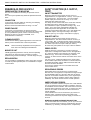
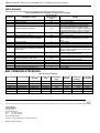
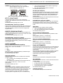
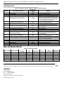
Table 5. SN DIFF Transmitter parameters
parameter
description
range
min. pressure
analog
pressure mapped to upper
(analog end minus
start-pt.
limit of output range
50%FS)
max. pressure
analog end- pressure mapped to lower
(analog start plus
pt.
limit of output range
50%FS)
user-adjustable offset to
compensate for local
±25%FS
offset
atmospheric pressure and
drift
0…20 mA, 4…20 mA
definition
selection of output signal
0…10 V, 2…10 V
selecting normal / inverted non-inverted;
function
output characteristics
inverted
weight (in %) of previous
attenuation
0 … 99
value in attenuation filter
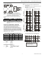
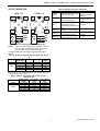
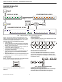
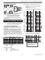
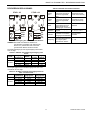
OUTPUT DESCRIPTION
PTHD...V3
1 L+/~
WARN
2
L-/~ 3
P
U/I
PTHD...A2
1
2
3
4
n.c.
2
4
U/IOUT
L+/~
WARN
L-/~
L-
P
L+
1
4
3
I
n.c.
1
2
3
4
L+
n.c.
Ln.c.
Fig. 16. Pin assignment of A-coded M12 plug
NOTE:
The unit and any field devices (actuators, sensors,
etc.) to which it is electrically connected must be
provided with a common ground via pin 3.
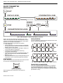
The initial conditions of the device's signal outputs are as
follows:
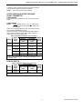
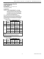
Table 3. SN DIFF Transmitter signal outputs after powerup
output
output
device
WARN
power
signal range
(pin 4)
2-Wire
4…20 mA
not used
< 3.6 mA
not used
4…20 mA
passive
-0 mA
2…10 V
passive
-2V
3-Wire
0…20 mA
passive
-0 mA
0…10 V
passive
-0V
The output limits of the device's outputs at overpressure and
underpressure are as follows:
Table 4. SN DIFF Transmitter output limits at over- /
underpressure
output signal min. output max. output
device
range
limit
limit
2-Wire
4…20 mA
3.8 mA
20.5 mA
4…20 mA
3.8 mA
20.5 mA
2…10 V
1.8 V
10.5 V
3-Wire
0…20 mA
0 mA
20.5 mA
0…10 V
0V
10.5 V
9
MU2B-0343GE51 R1109B