1
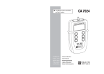
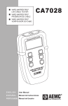
■ Wire Mapper ProTM Lan Cable Tester
CA 7028
C.A. P7P0ER2P8RO
WIRE MA
FRANÇAIS
Notice d’utilisation
ENGLISH
User’s manual
DEUTSCH
Bedienungsanleitung
I TA L I A N O
Libreto d’Istruzioni
E S PA Ñ O L
Manual de Instrucciones
1
English .......................................................................................................................................... 25
Deutsch ........................................................................................................................................ 47
Italiano .......................................................................................................................................... 69
Español ......................................................................................................................................... 91
TABLE DES MATIERES
1. INTRODUCTION ................................................................................................................................ 4
1.1 Réception de votre matériel ................................................................................................... 5
1.2 Informations concernant votre commande ........................................................................... 5
1.2.1 Accessoires : ......................................................................................................................... 5
1.2.2 Pièces de rechange ............................................................................................................... 5
2. CARACTERISTIQUES DU PRODUIT .............................................................................................. 6
2.1 Description ............................................................................................................................. 6
2.2 Caractéristiques de Wire Mapper Pro TM ............................................................................... 7
3. SPECIFICATIONS .............................................................................................................................. 8
4. FONCTIONNEMENT ....................................................................................................................... 10
4.1 Principes de fonctionnement ............................................................................................... 10
4.2 Type de câble/réseau et configuration générale ................................................................ 10
4.3 Détermination et mesure des valeurs de Vp ...................................................................... 11
4.4 Test de TNV (tension de réseau de télécommunication) et avertissement ...................... 12
4.5 Détection de fonctionnement ............................................................................................... 13
4.6 Fonctionnement général ...................................................................................................... 13
4.7 Ecran CONFORME/réussite du test ................................................................................... 14
4.8 Ecran d’échec du test ......................................................................................................... 15
4.8.1 Défaut circuit ouvert et court-circuit .................................................................................... 15
4.8.2 Défaut de paire séparée et paire inversée ........................................................................ 15
4.9 Défauts multiples .................................................................................................................. 16
4.10 Absence d’unité distante ..................................................................................................... 17
4.11 Mesure de longueur de câble ............................................................................................. 17
4.12 Générateur de tonalités ....................................................................................................... 18
4.13 Rétroéclairage ...................................................................................................................... 18
5. PROTOCOLE DE CABLAGE ......................................................................................................... 19
6. MAINTENANCE ............................................................................................................................... 22
6.1 Remplacement des piles ..................................................................................................... 22
6.2 Nettoyage ............................................................................................................................. 22
6.3 Stockage .............................................................................................................................. 22
6.4 Réparation et étalonnage ..................................................................................................... 22
6.5 Garantie ................................................................................................................................ 22
2
3
1. INTRODUCTION
AVERTISSEMENT
n
Cet instrument est conforme aux exigences de la norme
IEC61010-1:1965.
n
Le modèle C.A 7028 est conçu pour une utilisation sur des circuits
hors tension uniquement.
n
Tout branchement sur le secteur risque d'endommager l'instrument et
de présenter un danger pour l'opérateur.
n
Cet instrument est protégé contre les tensions des réseaux de télécommunication, conformément à la norme EN61326-1.
n
La sécurité relève de la responsabilité de l'opérateur !
1.1
Réception de votre matériel
L'ensemble du matériel a été vérifié du point de vue mécanique et électronique avant
expédition. Toutes les précautions nécessaires ont été prises pour vous assurer que vous
recevez l'instrument en bon état. Il vous est toutefois conseillé de vérifier rapidement qu'il
n'a pas été endommagé durant le transport. Si cela était le cas, avertissez immédiatement
le transporteur et émettez les réserves d'usage.
Attention ! Si vous expédiez cet instrument, utilisez de préférence l'emballage d'origine et
indiquez aussi clairement que possible les raisons de la réexpédition sur un bordereau
joint au matériel.
Remarque : nos produits sont brevetés en FRANCE et A L'ETRANGER ; nos logos sont des
marques déposées.
Nous nous réservons le droit de modifier les caractéristiques et prix de nos produits si les
progrès technologiques l'exigent.
1.2
Informations concernant votre commande
Wire Mapper ProTM Modèle C.A 7028 ............................................................... P01129501
Inclut instrument de mesure, boîtier de transport, identification à distance (No.1), 2 cordons
de raccordement, 4 piles 1,5 V AA, un manuel d'utilisation et la carte de garantie du produit.
Symboles électriques internationaux
1.2.1
Ce symbole signifie que l'instrument est protégé par une isolation double ou renforcée. Lors de toute intervention sur l'instrument, il est vivement conseillé d'utiliser exclusivement les pièces de rechange spécifiées.
Ce symbole figurant sur l'instrument indique un AVERTISSEMENT et signale que
l'opérateur doit se référer aux instructions du manuel d'utilisation avant de faire
fonctionner l'instrument. Dans ce manuel, le symbole précédant les instructions
indique que le non-respect de celles-ci peut entraîner des blessures corporelles
ou risque d'endommager le produit ou de provoquer des problèmes d'installation/
échantillonnage.
Accessoires :
Wire Mapper ProTM - Identificateurs à distance (No.2-5) ................................... P01101994
Wire Mapper ProTM - Identificateurs à distance (No.6-9) ................................... P01101995
1.2.2
Pièces de rechange
Wire Mapper ProTM – Identificateurs à distance No.1 ........................................ P01101992
2 cordons de raccordement RJ45 CA7028 ....................................................... P01295233
Risque d'électrocution. La tension qui s'applique sur les pièces comportant ce
symbole peut être dangereuse.
4
5
2. CARACTERISTIQUES DU PRODUIT
2.1
Description
2.2
Caractéristiques de Wire Mapper ProTM
1
Wire Mapper Pro TM est un testeur de câbles structuré portatif et appareil de dépannage
utilisé sur les câbles de type UTP, STP, FTP & SSTP équipés de connecteurs RJ45 et câblés
conformément aux spécifications TIA 568A/B (ISO11801 & EN50137), USOC ou RNIS/
ISDN. Il détecte les paires en circuit ouvert, fils croisés, paires croisées, paires inversées,
défauts de blindage et paires divisées.
En cas de circuit ouvert et court-circuit, Wire Mapper ProTM utilise la technologie de type
réflectomètre TDR (Time Domain Reflectometer) pour indiquer si le défaut est à l'extrémité
rapprochée du câble, à l'extrémité distante ou à un endroit quelconque entre les deux. Il
indique ensuite la distance par rapport au défaut.
Wire Mapper ProTM permet de mesurer et indiquer la longueur du câble testé, à l'aide de la
vitesse de propagation (Vp) définie par l'utilisateur. Il mesure et indique la longueur des 4
paires de fils du câble testé. Il génère également un signal sonore transmis aux 4 paires du
câble testé. Ceci permet de l'utiliser pour la localisation et l'identification des câbles.
Cet instrument permet également d'identifier les lignes téléphoniques et de transmission
de données. Si l'unité principale est branchée dans une prise RJ45 opérationnelle, elle
transmet un signal d'avertissement continu et l'écran approprié signale la présence d'une
tension téléphonique sur l'une des broches. Si l'opérateur appuie sur la touche de détection de fonctionnement, l'écran affiché indique une connexion 10base-T, Token-Ring et
100Mbit+.
Structured Cable Tester
Chauvin Arnoux
Wire Mapper Pro V1.0
2
TIA568 UTP Vp=75%
3
6
SERVICE / Vp
LENGTH / Vp
4
7
MAP /
5
C.A. 7028
Caractéristiques :
1
8
C.A. 7028
FAULT MAPPER PRO
WIRE MAPPER PRO
Remote Unit
9
n
Testeur de câble et détecteur de pannes portatif
n
Conçu pour une utilisation sur des câbles de type UTP, STP, FTP & SSTP
équipés de connecteurs RJ45 et câblés conformément aux spécifications
TIA 568A/B (ISO11801 & EN50137), USOC ou RNIS/ISDN.
n
Détecte les paires en circuit ouvert, fils croisés, paires croisées, paires
inversées, défauts de blindage et paires divisées.
n
Indique la localisation du défaut.
1.
n
Mesure et indique la longueur du câble testé.
2.
Ecran graphique à cristaux liquides
3.
Bouton de décrément de Vp (Vitesse de propagation)/Test de fonctionnement
4.
Bouton de sélection de fonction/test de configuration du câblage
n
Emet un signal sonore utilisé pour localiser un câble et identifier le type de
défaut.
Connecteur d'entrée RJ-45
5.
Bouton de rétroéclairage
n
Identifie les lignes téléphoniques et de transmission de données.
6.
Bouton d'incrément de Vp (Vitesse de propagation)/test de longueur de câble
n
Jusqu'à 16 identificateurs à distance sont disponibles
7.
Bouton de sélection de générateur de tonalité
6
8.
Bouton de marche/arrêt
9.
Unité d'identification à distance
7
3. SPECIFICATIONS
Température de stockage :
Température de fonctionnement :
Plage :
Précision* :
Types de câbles :
Défauts indiqués :
Localisation des défauts :
Modes de câblage :
Indications de fonctionnement :
Avertissement de tension :
Blocage de test :
Générateur de tonalités :
Durée de vie de la pile :
Affichage de l'unité principale :
Affichage des défauts :
Rétroéclairage :
Affichage à distance :
Langues :
Alimentation :
Coupure automatique :
Durée de vie de la pile :
150 m (500 pieds)
± 5%
UTP, STP, FTP & SSTP
Paire en court-circuit
Fil en circuit ouvert
Court-circuit entre paires
Paires croisées / divisées
Paires inversées
Continuité du blindage
Extrémité rapprochée, extrémité distante ou
distance si le défaut est entre les deux
TIA 568A/B, USOC & RNIS/ISDN, ISO11801,
EN50137
Téléphone, 10BaseT, 100Mbit+,
Token Ring
Avertissement de présence de TNV
(tension de réseau de télécommunication
Empêche tout test en la présence de
tensions de secteur
Générateur de tonalités oscillantes
810 Hz - 1110 Hz
0 à 100 % diagramme en bâtons de type
"jauge d'essence"
Affichage graphique à cristaux liquides
128 x 64 pixels
Affichage de tous les défauts et des infos
de configuration
sous forme de textes et graphiques
Electroluminescent
DEL verte/rouge
Anglais (américain et britannique), allemand,
français, espagnol, italien
4 piles alcalines 1,5 V AA
après 3 minutes
Mode veille > 4000 heures
Test continu > 7,5 heures
8
Poids de l'unité principale :
Dimensions de l'unité principale :
Poids de l'unité distante :
Dimensions de l'unité distante :
Sécurité :
CEM :
CE :
DES :
EM :
Impulsions rapides de signaux (burst):
FR conduite :
-20 à 70°C (-4 à 158°F)
5 à 95 % d'humidité relative sans condensation
0 à 40°C (32 à 112°F)
5 à 95 % d'humidité relative sans condensation
350 g (12 oz)
165 x 90 x 37 mm (6,5 x 3,5 x 1,5")
40 g (1,5 oz)
65 x 52 x 25 mm (2.5 x 2.0 x 1.0")
EC61010-1
EN61326-1
Conforme aux directives de l'UE en vigueur
EN61000-4-2
EN61000-4-3
EN61000-4-4
EN61000-4-6
9
Pour les câbles FTP et SSTP, utilisez la configuration STP.
4. FONCTIONNEMENT
•
4.1
La Vp peut être définie dans une plage de 20 % à 100 %.
(Si la valeur de Vp n'est pas connue, reportez-vous au paragraphe 4.3).
Principes de fonctionnement
•
Pour mettre en marche ou arrêter l'instrument, utiliser le bouton d'alimentation vert qui se
trouve en bas à droite du panneau frontal.
Wire Mapper ProTM peut être configuré pour mesurer la longueur de câble en
pieds ou en mètres.
•
Il peut être configuré pour fonctionner en anglais (américain ou britannique),
français, allemand, italien ou espagnol.
Chauvin Arnoux
Wire Mapper Pro V1.0
•
TIA568 UTP Vp=75%
Le contraste d'affichage peut être réglé en sélectionnant Contrast, puis en
appuyant sur le bouton
ton
LENGTH / Vp
SERVICE / Vp
pour augmenter le contraste ou le bou-
pour diminuer le contraste et améliorer l'affichage en fonc-
tion des conditions d'éclairage ambiantes. L'unité dispose également d'un
rétroéclairage.
Lors de la première mise en marche de l'unité, l'écran affiche la version du logiciel et l'état
de charge des piles.
•
Pour sortir du mode paramétrage, appuyez sur le bouton
.
Il affiche également le type de fil (TIA568, STP…) et la vitesse de propagation (Vp). Pour
modifier ces paramètres, voir paragraphe 4.2.
4.3
4.2
Les valeurs de la vitesse de propagation (Vp) sont caractéristiques de chaque type et
marque de câble. La Vp est utilisée pour mesurer la longueur d’un câble et l’emplacement
d’un défaut. Plus la Vp est précise, plus le résultat de la mesure est exact.
Type de câble/réseau et configuration générale
Pour entrer un menu de sélection de câble et réseau :
•
Appuyez sur le bouton
, puis sur le bouton MAP /
Le fabricant du câble peut mentionner la Vp sur sa fiche technique ou peut la fournir sur
demande. Cependant, cette valeur n’est parfois pas disponible. L’utilisateur peut vouloir la
déterminer spécifiquement afin de compenser les variations de lots de câbles, ou pour des
applications de câblages spéciales. La procédure est relativement facile :
.
Exemple d'affichage :
> Type = TIA568 STP
Vp = 71%
Feet
Eng (USA)
Contrast
Pour déplacer le sélecteur de ligne (>), appuyez sur le bouton MAP / . Lorsque la ligne
souhaitée est sélectionnée, vous pouvez appuyer sur les boutons SERVICE / Vp et LENGTH / Vp
pour incrémenter ou décrémenter les autres options de l'article sélectionné.
•
Détermination et mesure des valeurs de Vp
1.
Prenez un échantillon de câble en incréments de longueur (pieds ou mètres)
supérieurs à 20 m (60 pieds).
2.
Mesurez la longueur exacte du câble à l’aide d’un ruban gradué.
3.
Raccordez une extrémité du câble au Wire Mapper (voir paragraphe 4.11). Laissez l’extrémité libre et assurez-vous que les fils ne sont pas en court-circuit.
4.
Mesurez la longueur et réglez la Vp jusqu’à la longueur exacte soit affichée.
5.
Lorsque la longueur exacte est affichée, la Vp est définie.
Dans Type, vous pouvez effectuer les sélections suivantes :
TIA568 STP
TIA568 UTP
ISDN/RNIS
USOC UTP
USOC STP
NOTE : Pour tester la configuration du câblage conformément aux normes ISO11801 &
EN50137, le produit devra être réglé sur TIA568, qui est la norme équivalente.
10
11
4.4
Test de TNV (tension de réseau de télécommunication) et avertissement
4.5
Détection de fonctionnement
Pour détecter un port de données actif, branchez l’unité sur le port à tester à l’aide d’un petit
câble de raccordement, puis appuyez sur le bouton SERVICE / Vp .
Structured Cable Tester
Structured Cable Tester
SERVICE / Vp
Token Rng
100Mbit+
unknown Service
LENGTH / Vp
10base T
No Service
SERVICE / Vp
LENGTH / Vp
MAP /
MAP /
C.A. 7028
FAULT MAPPER PRO
C.A. 7028
FAULT MAPPER PRO
L’écran affiche le type de connexion de données ou de fonctionnement présent dans la
liste suivante :
Mettez l’unité en fonction et branchez-la sur le port à tester avec un cordon de raccordement court.
En présence d’une tension de réseau de télécommunication (TNV), l’unité émet un signal
sonore continu et affiche les éléments suivants :
Structured Cable Tester
!!!!
Tention téléphone
détectée sur
borne X
!!!!
SERVICE / Vp
LENGTH / Vp
MAP /
C.A. 7028
FAULT MAPPER PRO
Remote Unit
C.A. 7028
FAULT MAPPER PRO
NOTE : L’écran affiche la broche de la connexion RJ45, sur laquelle la tension est détectée.
4.6
Fonctionnement général
•
Régler l’instrument sur le type de câble et le plan de câblage souhaité (voir
paragraphe 4.2).
•
Assurez-vous qu’aucune tension de réseau de télécommunication ni de
réseau électrique n’est détectée (voir paragraphe 4.4).
12
•
Raccordez l’instrument à une extrémité du câble à tester.
•
Raccordez l’unité distante à l’autre extrémité du même câble.
•
Appuyez sur le bouton
MAP /
.
13
L’écran affiche brièvement le message suivant, pendant le test :
* * * * * * * * * * * * * * * * * * *
Test en
cours
4.8
Ecran d’échec du test
4.8.1
Défaut circuit ouvert et court-circuit
En cas de défaut de circuit ouvert, l’affichage est le suivant :
ID1
DEFAUT
TIA568
* * * * * * * * * * * * * * * * * * *
L=94ft
Vp=71%
Cet écran est rapidement suivi par l’écran de résultats du test.
4.7
•
Ecran OK/réussite du test
•
Ecran d’échec du test
Ecran conforme/réussite du test
ID1
VALIDE
TIA568
L=94ft
Vp=71%
•
4 5 1 2 3 6 7 8 S
En cas de défaut de court-circuit ouvert, l’affichage est le suivant :
ID1
DEFAUT
TIA568
4 5 1 2 3 6 7 8 S
Cable conforme
L=94ft
Vp=71%
Le côté gauche de l’écran affiche les informations concernant le test effec-
La première ligne indique l’identité unique de l’unité à distance active connectée à l’extrémité distante (dans ce cas ID1). Quinze unités distantes actives supplémentaires sont proposées en option (IDNo.2 à IDNo.16).
•
L’état du test est indiqué sur la deuxième ligne. La réussite du test est confirmée par un double «bip» de l’unité principale et un double clignotement de
la LED verte de l’unité distante active.
•
4 5 1 2 3 6 7 8 S
4 5 1 2 3 6 7 8 S
Court-circuit à 10 m
Pin 1 2
Dans ce cas, la partie graphique de l’écran montre également que le défaut est un courtcircuit entre les broches 1 et 2 et que le court-circuit est calculé en approximation de la
distance le long du câble ou de la liaison où il s’est produit.
4.8.2
Défaut de paire séparée et paire inversée
En cas de défaut de paire séparée , l’affichage est le suivant :
Ensuite, l’écran affiche les informations concernant le type de test sélectionné, ainsi qu’une valeur mesurée de la longueur de câble, de même que
le paramétrage de la Vp en cours.
•
4 5 1 2 3 6 7 8 S
Ouvert a l'extrémité
Borne 7
Notez que le mot défaut s’affiche sous l’ID1 du câble, accompagné d’un message détaillé
en bas de l’écran.
La partie graphique de l’écran montre également que le défaut est un circuit ouvert sur la
broche 7 à l’extrémité distante, en indiquant une rupture de la ligne sur ce point.
tué et l’état des résultats.
•
4 5 1 2 3 6 7 8 S
ID1
DEFAUT
TIA568
4 5 1 2 3 6 7 8 S
En cas de découverte d’un défaut, un message s’affiche, accompagné d’un
signal sonore sur l’unité principale et du clignotement de la LED rouge de
l’unité distante.
14
L=94ft
Vp=71%
4 5 1 2 3 6 7 8 S
Paire inversée
Pin 4 5
15
En cas de défaut de paire séparée, l’affichage est le suivant :
ID1
DEFAUT
TIA568
L=94ft
Vp=71%
4 5 1 2 3 6 7 8 S
4.10
Absence d’unité distante
Lorsqu’un test de configuration de câblage est effectué sans unité distante à l’extrémité
distante, l’écran suivant s’affiche :
? ? ? ? ? ? ? ? ? ? ? ? ? ? ?
4 5 1 2 3 6 7 8 S
Paire sÈparÈe
Pin 1 2 3 6
Réception à
l'extrémité absent
? ? ? ? ? ? ? ? ? ? ? ? ? ? ?
NOTE : Pour les câbles inférieurs à 2 m de long, le testeur est incapable de distinguer
une paire séparée.
Dans ce cas (câble trop court), l’écran suivant s’affiche brièvement, avant un écran signalant à l’utilisateur que le test de paire séparée n’a pas été effectué.
4.11
Mesure de longueur de câble
* * * * * * * * * * * * * * * * * * *
Trop court pour
test paire sÈparÈe
* * * * * * * * * * * * * * * * * * *
Structured Cable Tester
SERVICE / Vp
LENGTH / Vp
MAP /
4.9
Défauts multiples
C.A. 7028
FAULT MAPPER PRO
En cas de défauts multiples, ou lorsqu’un câble ou une liaison présente plus d’un défaut, le
testeur signale les défauts dans l’ordre de priorité suivant.
•
Courts-circuits
•
Paires inversées
Raccordez l’unité distante à une extrémité du câble et appuyez sur le bouton
•
Circuits ouverts
La longueur des quatre paires du câble est mesurée et les résultats s’affichent simultanément, selon l’illustration ci-dessous.
Par exemple, sur un câble présentant un circuit ouvert sur la broche 3 et un courtcircuit entre les broches 7 et 8, seul le court-circuit des broches 7 et 8 sera signalé.
Pr.
Pr.
Pr.
Pr.
4-5
1-2
3-6
7-8
LENGTH / Vp
.
64ft
64ft
----64ft
TIA568 UTP Vp=71%
Dans cet exemple, la longueur des paires 3 à 6 n’est pas indiquée, étant donné la présence
d’un défaut sur la paire qui empêche le circuit TDR de mesurer la longueur.
16
17
La longueur sera affichée dans l’unité sélectionnée (mètres ou pieds), et la norme de test
de câble et de Vp sera également affichée. La précision de la mesure de longueur dépend
du bon paramétrage de la vitesse de propagation (Vp) du câble testé.
Si la Vp n’est pas connue pour un câble donné, une longueur connue de ce câble (au
moins 20 m ou 60 pieds de long) peut être connectée à l’instrument et la Vp peut être
ajustée jusqu’à obtention de la mesure de longueur correcte (voir paragraphe 4-3).
4.12
Générateur de tonalités
Wire Mapper Pro™ peut aussi être utilisé comme générateur de tonalités, pour localiser et
identifier les câbles et fils. Pour cela, l’utilisateur a besoin d’une sonde de tonalités de
câbles, de type «Cable Tone Tracer».
5. PROTOCOLE DE CABLAGE
Les schémas suivants illustrent les défauts de câbles :
CABLE CONFORME
Le câble est en bon état
4
4
5
5
3
3
6
6
1
1
2
2
7
7
8
8
PAIRE OUVERTE
Structured Cable Tester
(OK)
Pair 1
Pair 2
Message:
Cable CONFORME
Pair 3
Pair 4
(OP)
Une paire spécifique est en circuit ouvert. Cela peut concerner un ou deux fils de la même
paire.
SERVICE / Vp
LENGTH / Vp
Une ou plusieurs paires peuvent également être ouvertes sur le même câble.
MAP /
C.A. 7028
FAULT MAPPER PRO
Toute pression sur la touche
injecte une tonalité oscillante dans le câble ou dans la
liaison testée. Après configuration, l’écran affiche les éléments suivants :
4
4
5
5
3
3
6
6
1
1
2
2
7
7
8
8
Pair 1
Pair 2
Message:
Ouvert ou
ouvert à l’extrémité
Pin 1 2
Pair 3
Pair 4
* * * * * * * * * * * * * * * * * * *
Signal sonore
PAIRE COURT-CIRCUITEE
(SH)
Une paire spécifique est en court-circuit.
* * * * * * * * * * * * * * * * * * *
Le signal injecté oscille entre 810 Hz et 1110 Hz, six fois par seconde.
NOTE : La fonction de coupure automatique est désactivée en mode générateur de tonalités, de sorte que la tonalité peut être injectée dans un câble pendant une durée prolongée
pendant la localisation.
4.13
4
4
5
5
3
3
6
6
1
1
2
2
7
7
8
8
Pair 1
Pair 2
Pair 3
Pair 4
Rétroéclairage
Pour mettre en marche ou arrêter le rétroéclairage, utiliser le bouton
18
.
19
Message:
Court-circuit ou
C. circuit ext.
(extrémité)
Pin 1 2
PAIRE INVERSEE
(RP)
PAIRES CROISEES (CP)
Les fils d'une paire spécifique sont inversés à une extrémité.
Deux paires sont croisées à une extrémité.
Une ou plusieurs paires peuvent également être inversées sur le même câble.
Une ou plusieurs paires peuvent être croisées sur le même câble.
4
4
4
4
5
5
5
5
3
3
3
3
6
6
1
1
2
2
7
7
8
8
Pair 1
Pair 2
Message:
Paire inversée
Pin 3 6
Pair 3
Pair 4
CONDUCTEUR COURT-CIRCUITE
(SW)
Deux fils de paires différentes sont en court-circuit.
4
5
5
3
3
6
6
1
1
2
2
7
7
8
8
Pair 1
Pair 2
6
1
1
2
2
7
7
8
8
Pair 2
Pair 3
Pair 4
Message:
C. circuit ext.
ou court-circuit
Pin 2 3
Pair 3
Pair 4
Une paire utilise un fil d'une autre paire. Le câble fonctionne, mais un phénomène de
diaphonie peut se produire. Une ou plusieurs paires peuvent être séparée sur le même
câble.
4
4
5
5
3
3
6
6
1
1
2
2
7
7
8
8
Pair 1
Pair 2
Pair 3
Pair 4
CONDUCTEURS CROISES
(CW)
Deux fils de paires différentes sont croisés à une extrémité.
Deux paires ou plus peuvent comporter des fils croisés avec une autre paire.
4
4
5
5
3
3
6
6
1
1
2
2
7
7
8
8
Pair 1
Pair 2
Pair 3
Message:
Cond. croisé extrém.
(Conducteur croisé extrémité
ou Conducteur croisé)
Pin 3 5
Pair 4
20
Message:
Paires croisées
Pin 3 6
PAIRES SEPAREES (SP)
Un fil et une paire ou plusieurs fils et paires peuvent être affecté(e)s sur le même câble.
4
6
Pair 1
21
Message:
Paires séparées
Pin 2 7
6. MAINTENANCE
Utiliser uniquement les pièces de rechange spécifiées par l'usine. Chauvin-Arnoux ne
saurait être tenu responsable d'accidents, incidents ou dysfonctionnements éventuels à la
suite d'une réparation effectuée par toute personne n'appartenant pas à son centre d'entretien ni à un centre de réparation agréé.
6.1
1.
mauvaise utilisation du matériel ou utilisation conjointement avec des équipements incompatibles.
2.
modifications du matériel sans autorisation explicite du service technique du fabricant.
3.
travaux exécutés sur l'instrument par une personne non agréée par le fabricant.
4.
adaptation à une application spécifique, non incluse dans la définition du matériel
ou dans le manuel d'utilisation.
5.
coups, chutes ou dégât des eaux.
Remplacement des piles
Débrancher de l'instrument tous les câbles ou liaisons réseau.
1.
La garantie ne s'applique pas dans les cas suivants :
Mettre l'instrument HORS tension.
2.
Desserrer les 2 vis et enlever le couvercle du compartiment batteries.
3.
Remplacer les piles par 4 piles alcalines 1,5 V AA, en respectant bien les polarités.
4.
Remettre en place et fixer le couvercle du compartiment batteries.
6.2
Nettoyage
Débrancher de l'instrument toute source d'alimentation électrique.
6.3
•
Utiliser un chiffon doux légèrement humidifié à l'eau savonneuse.
•
Rincer avec un chiffon humide, puis sécher avec un chiffon sec.
•
Ne pas asperger d'eau directement sur l'instrument.
•
Ne pas utiliser d'alcool, de solvants ni d'hydrocarbures.
Stockage
Si l'instrument n'est pas utilisé pendant une durée supérieure à 60 jours, il est conseillé
d'enlever les piles et de les stocker séparément.
6.4
Réparation et étalonnage
Informations et adresses disponibles sur demande :
Tél. : (33) (0)2.31.64.51.53 - Fax (33) (0) 2.31.64.51.09
6.5
Garantie
Ce matériel est garanti contre tout défaut matériel ou de fabrication, conformément aux
conditions générales de vente.
Durant la période de garantie (1 an), l'instrument doit être réparé exclusivement par le
fabricant, qui se réserve le droit de le réparer ou de l'échanger en tout ou partie. En cas de
retour de l'instrument au fabricant, les frais de transport sont à la charge du client.
22
23
TABLE OF CONTENTS
1. INTRODUCTION ........................................................................................................................... 26
1.1 Receiving Your Shipment ..................................................................................................... 27
1.2 Ordering Information ............................................................................................................ 27
1.2.1 Accessories and Replacement Parts: ................................................................................ 27
1.2.2 Replacement parts ............................................................................................................... 27
2. PRODUCT FEATURES ................................................................................................................. 28
2.1 Description ........................................................................................................................... 28
2.2 Wire Mapper Pro™ Features ............................................................................................... 29
3. SPECIFICATIONS .......................................................................................................................... 30
4. OPERATION .................................................................................................................................. 32
4.1 Getting Started ..................................................................................................................... 32
4.2 Cable/Network Type and General Setup ........................................................................... 32
4.3 Determining and Measuring Vp Values .............................................................................. 33
4.4 TNV (Telecom Network Voltage) Testing and Warning ...................................................... 34
4.5 Service Detection ................................................................................................................. 35
4.6 General Operation ............................................................................................................... 35
4.7 Test Pass/OK Screen .......................................................................................................... 36
4.8 Test Failed Screen ................................................................................................................ 37
4.8.1 Open and Short Fault .......................................................................................................... 37
4.8.2 Reversed and Split Pair Fault .............................................................................................. 37
4.9 Multiple Faults ....................................................................................................................... 38
4.10 Missing Remote .................................................................................................................... 39
4.11 Cable Length Measurement ................................................................................................ 39
4.12 Tone Generator .................................................................................................................... 40
4.13 Backlight ............................................................................................................................... 40
5. WIRE PROTOCOL ........................................................................................................................ 41
6. MAINTENANCE ............................................................................................................................. 44
6.1 Changing the Battery ........................................................................................................... 44
6.2 Cleaning ................................................................................................................................ 44
6.3 Storage ................................................................................................................................. 44
6.4 Repair and calibration .......................................................................................................... 44
6.5 Warranty : ............................................................................................................................. 44
24
25
1. INTRODUCTION
1.1
WARNING
n
This instrument meets the safety requirements of IEC61010-1:1995.
n
The Model CA7028 is designed for use on de-energized circuits only.
n
Connection to line voltages will damage the instrument and could be
hazardous to the operator.
n
This instrument is protected against connection to telecom network
voltages according to EN61326-1.
n
Safety is the responsibility of the operator.
Receiving Your Shipment
Upon receiving your shipment, make sure that the contents are consistent with the packing
list. Notify your distributor of any missing items. If the equipment appears to be damaged, file
a claim immediately with the carrier and notify your distributor at once, giving a detailed
description of any damage. Save the damaged packing container to substantiate your
claim.
Caution ! if you ship this instrument on elsewhere, use preferably the original packaging
and indicate the reasons for reshipment as clearly as possible in a note enclosed with the
equipement.
Note : our products are patented in France and Abroad. Our logos are registrered trade
marks.
E reserved the right to modify the characteristics and prices should technological advances
make it necessary.
1.2
Ordering Information
Wire Mapper Pro™ Model CA7028 .................................................................. P01129501
International Electrical Symbols
This symbol signifies that the instrument is protected by double or reinforced
insulation. Use only specified replacement parts when servicing the instrument.
This symbol on the instrument indicates a WARNING and that the operator must
refer to the user manual for instructions before operating the instrument. In this
manual, the symbol preceding instructions indicates that if the instructions are not
followed, bodily injury, installation/sample and product damage may result.
Includes meter, carrying case, remote ID (#1), 2 patch cords, 4 x 1.5 AA batteries, user
manual and a product warranty card.
1.2.1
Wire Mapper Pro™ Remote IDs (#2-5) ............................................................... P01101992
Wire Mapper Pro™ Remote IDs (#6-9) ............................................................... P01295233
Cable Tone Trace .................................................................................... (consulut factory)
1.2.2
Risk of electric shock. The voltage at the parts marked with this symbol may be
dangerous.
26
Accessories and Replacement Parts:
Replacement parts
Wire Mapper ProMT remote ID #1 ........................................................................ P01101992
2 patch cords RJ45 CA 7028 ............................................................................. P01295233
27
2. PRODUCT FEATURES
2.1
Description
2.2
Wire Mapper Pro™ Features
1
The Wire Mapper Pro™ is a hand-held structured cable tester and troubleshooter designed
for use on UTP, STP, FTP & SSTP cabling equipped with RJ45 connectors and wired to either
TIA 568A/B (ISO11801 & EN50137), USOC or ISDN specifications. It detects open circuit
pairs, shorts, crossed wires, crossed pairs, reversed pairs, shield faults and split pairs.
Structured Cable Tester
In the event of opens and shorts, the Wire Mapper Pro™ uses TDR technology to indicate if
the fault is at the near end of the cable, the remote end, or if it is somewhere in between. It
will then indicate the distance to the fault.
2
The Wire Mapper Pro™ has the ability to measure and indicate the length of the cable under
test, using a Vp (Velocity of Propagation), set by the user. It will measure and report the
length of all 4 pairs of wires in the cable under test. It also generates an audible tone that is
transmitted into all 4 pairs on the cable under test. This can be used for cable tracing and
identification.
3
This instrument also has the ability to identify telephone and data lines. If the main unit is
plugged into an operational RJ45 socket, it will give a continuous warning tone and
appropriate display if a telephone voltage is present on any of the pins. If the Service Detect
key is pressed, it will give a display distinguishing 10base-T, Token Ring and 100Mbit+
connections.
Chauvin Arnoux
Wire Mapper Pro V1.0
TIA568 UTP Vp=75%
6
SERVICE / Vp
LENGTH / Vp
4
7
MAP /
5
1
8
Features:
n
n
n
C.A. 7028
Hand-held cable and troubleshooting tester
Designed for use on UTP, STP, FTP & SSTP cabling equipped with RJ45
connectors and wired to either TIA568A/B (ISO11801 & EN50137), USOC
or ISDN specifications.
n
Detects open circuit pair, shorts, crossed wires, crossed pairs, reversed
pairs, shield faults and split pairs.
Indicates location of the fault
n
Measures and indicates the length of the cable under test
n
Emits an audible tone, used to trace a cable and identify the type of fault
n
Identifies telephone and data lines
n
Up to 16 Remote IDs identified
28
C.A. 7028
FAULT MAPPER PRO
WIRE MAPPER PRO
Remote Unit
9
1.
RJ-45 input connector
2.
Graphical LCD
3.
Service Test/Vp (Velocity of Propogation) decrement button
4.
Wire map test/function select button
5.
Backlight button
6.
Cable Length Test/Vp (Velocity of Propogation) increment button
7.
Tone generator select button
8.
Power ON/OFF button
9.
Remote ID Unit
29
3. SPECIFICATIONS
Range:
Accuracy:
Cable Types:
Faults Indicated:
Fault Location:
Wiring Schemes:
Service Indication:
Voltage Warning:
Test Inhibit:
Tone Generator:
Battery indicator:
Main Unit Display:
Fault Display:
Display Backlight:
Remote Display:
Languages:
Power Supply:
Auto Power Off:
Battery Life:
Storage Temperature:
Operating Temperature:
Main Unit Weight:
Main Unit Dimensions:
Remote Weight:
500 ft (150m)
±5%
UTP, STP, FTP & SSTP
Short Circuit Pair
Open Circuit Wire
Short Between Pairs
Split / Cross Pairs
Pair Reversals
Shield Continuity
Near End, Remote End, or distance
if midway
TIA 568A/B, USOC & ISDN
Telephone, 10BaseT, 100Mbit+,
Token Ring
Warns of TNV (Telecom Network
Voltage) presence
Inhibits Testing in the presence of
live voltages
Tone generator (oscillating) 810Hz - 1110Hz
0 to 100% "Gas Gauge" Bargraph
128 x 64 pixel Graphical LCD
All fault and setting info displayed
textually and graphically
Electroluminescent
Green/Red LED
English (USA and UK), German,
French, Spanish, Italian
4 x 1.5V AA alkaline batteries
after 3 minutes
Standby mode >4000hrs
Continuous testing >7.5hrs
-4 to 158°F (-20 to 70°C)
5 to 95% RH non-condensing
32 to 112°F (0 to 40°C)
5 to 95% RH non-condensing
12 oz (350g)
6.5 x 3.5 x 1.5" (165 x 90 x 37mm)
1.5 oz (40g)
30
Remote Dimensions:
Safety:
EMC:
CE:
ESD:
EM:
Burst:
Conducted RF:
2.5 x 2.0 x 1.0" (65 x 52 x 25mm)
IEC61010-1
EN61326-1
Compliant with current EU directives
EN61000-4-2
EN61000-4-3
EN61000-4-4
EN61000-4-6
31
For FTP and SSTP cables use the STP setting.
4. OPERATION
•
4.1
Vp is selectable in the range 20% to 100%.
(see § 4.3 if the Vp is not known)
Getting Started
•
The instrument is switched on and off using the green power button found on the lower right
side of the front panel.
The Wire Mapper Pro™ may be set to measure cable length in feet or
meters.
•
The instrument may be set to operate in English (USA or UK), French,
German, Italian or Spanish.
Chauvin Arnoux
Wire Mapper Pro V1.0
•
TIA568 UTP Vp=75%
The display contrast may be set by selecting Contrast and then pressing
the
SERVICE / Vp
button to decrease the contrast or the LENGTH / Vp
button
to increase the contrast and optimize the display to the ambient lighting
conditions. The unit also has a display backlight.
When the unit is first switched on, it will display the opening screen giving the software
version and remaining battery capacity.
The wire type (TIA568, STP...) and the Vp (Velocity of Propogation) is also displayed. The
change these settings, see § 4.2 below.
4.2
To enter a menu for Cable and Network selection:
Press down on the
4.3
To exit set up mode, press the
, button, then press the MAP /
button.
Typical display:
> Type = TIA568 STP
Vp = 71%
Feet
Eng (USA)
Contrast
Determining and Measuring Vp Values
The cable manufacturer may list the Vp on their specification sheet or may be able to
provide it when asked. Sometimes this value is not readily available, or the user may wish to
determine it specifically to compensate for cable batch variations, or for special cable
applications. This is quite easy:
1.
Take a cable sample of exact length increments (ft or m) longer than 60ft (20m).
2.
Measure the exact length of the cable using a tape measure.
3.
Connect one end of the cable to the Wire Mapper Pro™ (see § 4.11).
Leave the end un-terminated and make sure the wires do not short to each other.
4.
Measure the length and adjust the Vp until the exact length is displayed.
5.
When the exact length is displayed, Vp is established.
The > (line selector) is moved by pressing the MAP / button. When the appropriate line is
and LENGTH / Vp buttons may be pressed to increment or
selected, the SERVICE / Vp
decrement through the alternative options for the selected item.
•
Under Type, the following selections can be made:
TIA568 STP
TIA568 UTP
ISDN/RNIS
USOC UTP
USOC STP
NOTE: For testing of wiremap in accordance with ISO11801 & EN50137 the product should
be set to TIA568 which is the equivalent standard.
32
button.
Vp, or Velocity of Propagation, values are characteristic of each cable type and brand. The
Vp is used to measure the length of a cable and to measure a fault location. The more
accurate the Vp, the more accurate the measurement result will be.
Cable/Network Type and General Setup
•
•
33
4.4
TNV (Telecom Network Voltage) Testing and Warning
Turn the unit on and plug it into the port to be tested with a short patch cord.
4.5
Service Detection
To detect an active data port, plug the unit into the port to be tested using a short patch cable
and press the SERVICE / Vp button.
Structured Cable Tester
Structured Cable Tester
SERVICE / Vp
Token Rng
100Mbit+
unknown Service
LENGTH / Vp
10base T
No Service
SERVICE / Vp
LENGTH / Vp
MAP /
MAP /
C.A. 7028
FAULT MAPPER PRO
C.A. 7028
FAULT MAPPER PRO
If a Telecom Network Voltage is present, the unit will give a continuous audible warning, and
display the following:
The display will show the type of data connection or service present from the following
list:
!!!!
Telephone Voltage
detected on
Pin X
!!!!
Structured Cable Tester
NOTE: The pin on the RJ45 connection, on which the voltage is detected, is displayed.
SERVICE / Vp
LENGTH / Vp
MAP /
C.A. 7028
FAULT MAPPER PRO
Remote Unit
C.A. 7028
FAULT MAPPER PRO
4.6
General Operation
•
Set the instrument to the desired cable type and wiring scheme (see § 4.2).
•
Make sure no Telecom Network Voltages or other services are detected
(see § 4.4).
34
•
Attach the instrument to one end of the cable to be tested
•
Attach the remote unit to the other end of the same cable
•
Press the
MAP /
button.
35
The display will briefly show the following message while testing is being performed:
* * * * * * * * * * * * * * * * * * *
Test in
Progress
4.8
Test Failed Screen
4.8.1
Open and Short Fault
In the event of an Open fault, the following is displayed:
ID1
FAILED
TIA568
* * * * * * * * * * * * * * * * * * *
L=94ft
Vp=71%
This screen is quickly followed by the test results screen.
4.7
•
Test Pass/OK Screen
•
Test Failed Screen
Test Pass/OK Screen
ID1
PASS
TIA568
L=94ft
Vp=71%
•
4 5 1 2 3 6 7 8 S
In the event of a Short fault, the following is displayed:
4 5 1 2 3 6 7 8 S
Cable OK
ID1
FAILED
TIA568
L=94ft
Vp=71%
The first line shows the unique identity of the active remote unit connected
available as optional accessories (ID#2 to ID#16).
The test status, PASS is indicated on the second line. A test PASS is
confirmed by a double beep from the main unit and a double green flash
•
4 5 1 2 3 6 7 8 S
The left side of the display shows information about the test performed and
to the far end (in this case, ID1). There are 15 additional active remote units
•
4 5 1 2 3 6 7 8 S
Open at remote end
Pin 7
Notice the word FAILED under the cable ID1 and also the detailed message at the bottom
of the display.
The graphical portion of the display also shows that the fault is an open on pin 7 at the
remote end by showing a break in the line at this point.
the status of the test result.
•
4 5 1 2 3 6 7 8 S
4 5 1 2 3 6 7 8 S
Short at 36ft
Pin 1 2
In this situation, the graphical portion of the display also shows that the fault is a short
between pins 1 and 2 and the short is drawn at an approximation to the distance along the
cable or link under test, at which it occurs.
on the LED of the active remote unit.
4.8.2
Next, information about the test type selected, along with a measured value
In the event of a Reversed Pair fault, the following is displayed:
Reversed and Split Pair Fault
of the cable length, and an indication of the current VP setting is displayed.
•
If a fault is found an appropriate message will be displayed, along with a
warning tone on the main unit, and a red flashing LED on the remote unit.
ID1
FAILED
TIA568
L=94ft
Vp=71%
36
4 5 1 2 3 6 7 8 S
4 5 1 2 3 6 7 8 S
Reversed Pair
Pin 4 5
37
In the event of a Split Pair fault, the following is displayed:
ID1
FAILED
TIA568
L=94ft
Vp=71%
4 5 1 2 3 6 7 8 S
4.10
Missing Remote
If a wire map test is performed without a remote unit connected at the far end, the following
screen will be displayed:
? ? ? ? ? ? ? ? ? ? ? ? ? ? ?
4 5 1 2 3 6 7 8 S
Split Pair
Pin 1 2 3 6
Missing
Remote Unit
? ? ? ? ? ? ? ? ? ? ? ? ? ? ?
NOTE: For cables less than 6 ft (2m) in length the tester is unable to distinguish a Split
Pair condition.
In this event (cable too short), the following screen is displayed briefly, before the screen to
warn the user that a Split Pair test has not been carried out.
4.11
Cable Length Measurement
* * * * * * * * * * * * * * * * * * *
Too Short for
Split Pair Test
* * * * * * * * * * * * * * * * * * *
Structured Cable Tester
SERVICE / Vp
LENGTH / Vp
MAP /
4.9
Multiple Faults
C.A. 7028
FAULT MAPPER PRO
In the event of a multiple fault, or a cable or link with more than one fault on it, the tester will
report the faults in the following order of priority.
•
Shorts
•
Reversals
Attach the main unit to one end of the cable and press the
•
Opens
The length of all four pairs in the cable are measured, and the results displayed
simultaneously, as shown below.
For example, on a cable with an Open on pin 3 and a Short between pins 7 and 8, only the
Short in pins 7 and 8 will be reported.
Pr.
Pr.
Pr.
Pr.
4-5
1-2
3-6
7-8
LENGTH / Vp
button.
64ft
64ft
----64ft
TIA568 UTP Vp=71%
In this example, the length of pair 3 - 6 is missing, as there is a fault on the pair which is
preventing the TDR circuit from measuring the length.
38
39
Length will be displayed in the selected units, either meters or feet, and the Vp and cable
testing standard will also be displayed. Length measurement accuracy depends on the
correct setting of the Vp (Velocity of Propagation) for the cable under test.
If the Vp is not known for a particular cable, then a known length of that cable (at least 60ft
or 20m long) may be connected to the instrument and the Vp adjusted until the correct
length reading is obtained (see § 4.3).
4.12
Tone Generator
The Wire Mapper Pro™ may also be used as a tone generator, to trace and identify cables
and wires. The user will need a cable tone tracer, such as the AEMC Cable Tone Tracer
(consult factory) or equivalent.
5. WIRE PROTOCOL
The following drawings are examples depicting cable faults:
CABLE OK
4
4
5
5
3
3
6
6
1
1
2
2
7
7
8
8
OPEN PAIR
Structured Cable Tester
(OK)
Cable is good.
Pair 1
Message: Cable OK
Pair 2
Pair 3
Pair 4
(OP)
One specific pair is open. It may be one or two wires in the same pair.
One or more pairs may also be opened in the same cable.
SERVICE / Vp
LENGTH / Vp
MAP /
C.A. 7028
FAULT MAPPER PRO
Pressing the
key will inject a warbling (oscillating) tone into the cable or link under test.
When set, the following will be displayed:
* * * * * * * * * * * * * * * * * * *
4
4
5
5
3
3
6
6
1
1
2
2
7
7
8
8
SHORTED PAIR
Pair 1
Pair 2
Message:
Open at Near End
or Remote End
Pin 1 2
Pair 3
Pair 4
(SH)
One specific pair is shorted.
Warble Tone
* * * * * * * * * * * * * * * * * * *
The injected signal oscillates between 810Hz and 1110Hz, six times per second.
NOTE: The auto-off function is disabled in Tone Generator mode, so that the tone can be
injected into a cable for an extended period of time while tracing takes place.
4.13
4
4
5
5
3
3
6
6
1
1
2
2
7
7
8
8
Pair 1
Pair 2
Pair 3
Pair 4
Backlight
The display backlight is switched on and off with the
40
button.
41
Message:
Open at Remote End
or Near End
Pin 1 2
REVERSED PAIR
(RP)
CROSSED PAIRS
(CP)
The wires in one specific pair are Reversed at one end.
Two pairs are crossed at one end.
One or more pairs may be reversed in the same cable.
Two or more pairs may be crossed in the same cable.
4
4
5
5
3
3
6
6
1
1
2
2
7
7
8
8
SHORTED WIRES
Pair 1
Pair 2
Message:
Reversed pair
Pin 3 6
4
4
5
5
3
3
6
6
Pair 3
1
1
2
2
Pair 4
7
7
8
8
(SW)
Pair 1
Pair 2
Message:
Crossed Pairs
Pin 1 2 7 8
Pair 3
Pair 4
SPLIT PAIRS (SP)
Two wires from different pairs are shorted.
One pair uses one wire from another pair. The cable will work, but cross-talk may occur.
Two or more wires and pairs may be affected in the same cable.
Two or more pairs in the same cable may be split.
4
4
5
5
3
3
6
6
1
1
2
2
7
7
8
8
CROSSED WIRES
Pair 1
Pair 2
Message:
Short at Remote End
or Near End
Pin 2 3
Pair 3
Pair 4
4
4
5
5
3
3
6
6
1
1
2
2
7
7
8
8
Pair 1
Pair 2
Pair 3
Pair 4
(CW)
Two wires from different pairs are crossed at one end.
Two or more pairs may have wires crossed with another pair.
4
4
5
5
3
3
6
6
1
1
2
2
7
7
8
8
Pair 1
Pair 2
Message:
Crossed Wires
pin 3 5 at Remote
End or Near End
Pair 3
Pair 4
42
43
Message:
Split Pairs
Pin 2 7
6. MAINTENANCE
The warranty is not applicable in the following cases :
1.
improper use of the equipment or use of it in conjunction with incompatible
equipment ;
Use only factory specified replacement parts. AEMC® will not be held responsible for any
accident, incident, or malfunction following a repair done other than by its service center or
by an approved repair center.
2.
Modification to the equipment without the explicit autorisation of the manufacturer's
technical department
3.
Work carried out on the instrument by a person not approved by the manufacturer ;
6.1
4.
Adaptation for a specific application, not included in the definition of the equipment
or the user's manual ;
5.
Knocks, falls or flooding.
Changing the Battery
Disconnect the instrument from any cable or network link.
1.
Turn the instrument OFF.
2.
Loosen the 2 screws and remove the battery compartment cover.
3.
Replace the batteries with 4 x 1.5V AA alkaline cells, observing the polarities.
4.
Reattach the battery compartment cover.
6.2
Cleaning
Disconnect the instrument from any source of electricity
6.3
•
Use a soft cloth lightly dampened with soapy water.
•
Rinse with a damp cloth and then dry with a dry cloth.
•
Do not splash water directly on the instrument.
•
Do not use alcohol, solvents or hydrocarbons.
Storage
if the instrument is not used for aperiod of more than 60 days, it is recommended to remove
the batteris and store them separately.
6.4
Repair and calibration
Information and adress details available on request :
Tél. (33) (0)2.31.64.51.53 - Fax (33) (0)2.31.64.51.09
6.5
Warranty :
This equipment is guaranteed against anay material or manufacturing defects, in accordance
with the general conditions of sale.
During the warranty period (1 year), the isntrument can only be repaired by the manufacturer, who reserves the right to repair the instrument or to exchange all or part of it. If the
equipment is returned to the manufacturer, the outgoing transport costs are borne by the
customer.
44
45
INHALT
1. EINFÜHRUNG ............................................................................................................................... 48
1.1 Erhalt der Lieferung ............................................................................................................. 49
1.2 Bestellangaben .................................................................................................................... 49
1.2.1 Zubehör: ............................................................................................................................... 49
1.2.2 Ersatzteile ............................................................................................................................. 49
2. PRODUKTMERKMALE ................................................................................................................ 50
2.1 Beschreibung ....................................................................................................................... 50
2.2 Merkmale des Wire Mapper Pro TM ...................................................................................... 51
3. ALLGEMEINE DATEN .................................................................................................................. 52
4. BETRIEB ........................................................................................................................................ 54
4.1 Erste Schritte ........................................................................................................................ 54
4.2 Kabel-/Netzwerktyp und Allgemeines Setup ..................................................................... 54
4.3 Bestimmung und Messung von Vp-Werten ....................................................................... 55
4.4 TNV (Telefonnetzspannung) Prüfung und Warnung ......................................................... 56
4.5 Diensterkennung .................................................................................................................. 57
4.6 Allgemeiner Betrieb .............................................................................................................. 57
4.7 Bildschirm Prüfung bestanden/OK ..................................................................................... 58
4.8 Bildschirm Prüfung nicht bestanden ................................................................................... 59
4.8.1 Fehler: Unterbrechung und Kurzschluss ........................................................................... 59
4.8.2 Fehler: Vertauschte und Getrennten Paare ........................................................................ 59
4.9 Mehrfachfehler ..................................................................................................................... 60
4.10 Fehlendes Remote-Signal .................................................................................................... 61
4.11 Kabellängenmessung .......................................................................................................... 61
4.12 Tongenerator ........................................................................................................................ 62
4.13 Beleuchtung ......................................................................................................................... 62
5. LEITUNGSPROTOKOLL ............................................................................................................. 63
6. WARTUNG ..................................................................................................................................... 66
6.1 Auswechseln der Batterien .................................................................................................. 66
6.2 Reinigung .............................................................................................................................. 66
6.3 Lagerung .............................................................................................................................. 66
6.4 Reparatur und Eichung ....................................................................................................... 66
6.5 Garantie ................................................................................................................................ 66
46
47
1. EINFÜHRUNG
1.1
Erhalt der Lieferung
Das gesamte Gerät wurde vor dem Versand mechanisch und elektrisch überprüft.
Es wurden alle Vorsichtsmaßnahmen getroffen, damit das Gerät unbeschädigt bei Ihnen
eintrifft.
ACHTUNG
n
Dieses Gerät entspricht den Sicherheitsanforderungen IEC610101:1995.
n
Das Modell C.A 7028 darf nur an nicht unter Spannung stehenden
Kreisen eingesetzt werden.
n
Ein Anschluss an die Netzspannung beschädigt das Gerät und stellt
eine Gefahr für den Bediener dar.
n
Dieses Gerät ist gegen Spannungen, die in Telekommunikationsnetzen
auftreten, gemäß EN61326-1 geschützt.
n
Die Sicherheit liegt in der Verantwortung des Bedieners.
Es ist jedoch immer hilfreich, eine kurze Überprüfung durchzuführen, um festzustellen, ob
während des Transports Beschädigungen aufgetreten sind.
Wenn Sie Schäden am Gerät erkennen, reklamieren Sie diese sofort beim Spediteur und
setzen Sie umgehend Ihren Händler davon in Kenntnis.
Vorsicht!
Bei einer Rücksendung sollte möglichst die Originalverpackung verwendet
werden; geben Sie in einer dem Gerät beigelegten Erklärung die Gründe für die Rücksendung
so genau wie möglich an.
Hinweis: Unsere Produkte sind in FRANKREICH und anderen Ländern patentiert. Unsere
Logos sind eingetragene Warenzeichen.
Wir behalten uns das Recht vor, aufgrund technischer Weiterentwicklungen die Daten und
Preise unserer Produkte zu ändern
1.2
Bestellangaben
Wire Mapper ProTM C.A 7028 ............................................................................ P01129501
Internationale elektrische Symbole
Bestehend aus Messgerät, Tragekoffer, Remote-ID (Nr. 1), 2 Patch-Kabeln, 4 x 1,5V-AlkaliBatterien Typ AA, Bedienungsanleitung und Garantiekarte.
Dieses Symbol bedeutet, dass das Gerät über eine Schutzisolierung verfügt.
Verwenden Sie für die Wartung des Geräts nur die angegebenen Ersatzteile.
1.2.1
Zubehör:
Wire Mapper ProTM Remote-ID (Nr. 2 - 5) ........................................................... P01101994
Dieses Symbol am Gerät bedeutet ACHTUNG. Lesen Sie vor dem Betrieb des
Geräts unbedingt die Bedienungsanleitung. Werden die Anweisungen in dieser
Bedienungsanleitung, denen dieses Symbol vorangestellt ist, nicht beachtet oder
eingehalten, kann es zu Verletzungen von Menschen oder Beschädigungen des
Geräts oder der Installationen kommen.
Wire Mapper ProTM Remote-ID (Nr. 6 - 9) ........................................................... P01101995
1.2.2
Ersatzteile
Wire Mapper ProTM Remote-ID Nr.1 ................................................................... P01101992
2 Patch-Kabel RJ45 C.A 7028 ........................................................................... P01295233
Gefahr von Stromschlägen. Die Spannung an den mit diesem Symbol
gekennzeichneten Teilen kann gefährlich sein.
48
49
2. PRODUKTMERKMALE
2.1
Beschreibung
2.2
Merkmale des Wire Mapper ProTM
1
Der Wire Mapper Pro TM ist ein tragbares Kabelprüf- und Fehlersuchgerät für UTP-, STP-,
FTP- & SSTP-Verkabelungen, die mit RJ45-Anschlüssen ausgestattet und entweder nach
TIA 568A/B- (ISO11801 & EN50137), USOC- oder ISDN-Spezifikation verdrahtet sind. Er
erkennt unterbrochene Paare, Kurzschlüsse, gekreuzte Drähte, gekreuzte Paare, vertauschte
Paare, Abschirmungsfehler und geteilte Paare.
Bei Unterbrechungen und Kurzschlüssen verwendet der Wire Mapper Pro™ die TDRTechnik zur Ermittlung, ob sich der Fehler am nahen Ende des Kabels, am entfernten Ende
oder irgendwo dazwischen befindet. Anschließend gibt er die Entfernung zum Fehler an.
Der Wire Mapper ProTM verwendet zur Messung und Angabe der Länge eines zu prüfenden
Kabels eine vom Benutzer einstellbare Ausbreitungsgeschwindigkeit Vp. Er misst die Länge
aller 4 Leitungspaare des zu prüfenden Kabels und zeigt diese an. Außerdem erzeugt er
ein akustisches Signal, das in alle 4 Paare des zu prüfenden Kabels eingespeist wird.
Diese Funktion kann zur Suche und Identifizierung von Kabeln verwendet werden.
Das Gerät kann außerdem Telefon- und Datenleitungen identifizieren. Wird das Hauptgerät
mit einer betriebsfähigen RJ45-Buchse verbunden, ertönt ein ununterbrochener Warnton
und eine entsprechende Meldung wird angezeigt, wenn an einem der Pins eine
Telefonspannung anliegt. Wird die Taste "Service Detect" (Diensterkennung) gedrückt, zeigt
das Gerät an, an welche Art von Netzwerk es angeschlossen ist: 10base-T, Token Ring
oder 100 Mbit+.
Structured Cable Tester
Chauvin Arnoux
Wire Mapper Pro V1.0
2
TIA568 UTP Vp=75%
3
6
SERVICE / Vp
LENGTH / Vp
4
7
MAP /
5
1
8
C.A. 7028
Merkmale:
C.A. 7028
FAULT MAPPER PRO
WIRE MAPPER PRO
n
Tragbares Kabelprüf- und Fehlersuchgerät
n
Für UTP-, STP-, FTP- & SSTP-Verkabelungen, die mit RJ45-Anschlüssen
ausgestattet und entweder nach TIA 568A/B- (ISO11801 & EN50137),
USOC- oder ISDN-Spezifikationen verdrahtet sind
n
Erkennt unterbrochene Paare, Kurzschlüsse, gekreuzte Drähte, gekreuzte
Paare, vertauschte Paare, Abschirmungsfehler und geteilte Paare
n
Gibt die Lage des Fehlers an
n
n
Misst die Länge eines zu prüfenden Kabels und zeigt sie an
Gibt ein akustisches Signal zur Suche eines Kabels und zur Identifizierung
des Fehlertyps aus
n
Identifiziert Telefon- und Datenleitungen
n
Bis zu 16 Remote-IDs identifizierbar
50
Remote Unit
9
1.
RJ-45-Eingangsanschluss
2.
LCD-Grafikdisplay
3.
Taste Dienstprüfung/Herabsetzen Vp (Ausbreitungsgeschwindigkeit)
4.
5.
Auswahltaste Kabelprüfung/Betrieb
Taste für Beleuchtung
6.
Taste Kabellänge/Herabsetzen Vp (Ausbreitungsgeschwindigkeit)
7.
Auswahltaste Tongenerator
8.
Taste EIN/AUS
9.
Remote-ID-Gerät
51
3. ALLGEMEINE DATEN
Bereich:
Genauigkeit:
Kabeltypen:
Angezeigte Fehler:
Lage des Fehlers:
Verdrahtungsarten:
Dienstangabe:
Spannungswarnung:
Prüfsperre:
Tongenerator:
Batterieanzeige:
Display des Hauptgeräts:
Fehler-Display:
Display-Beleuchtung:
Remote-Display:
Sprachen:
Stromversorgung:
Auto-Off:
Batterie-Lebensdauer:
Lagertemperatur:
150 m (500 ft)
±5 %
UTP, STP, FTP & SSTP
Kurzschlusspaar
Unterbrochene Leitung
Kurzschluss zwischen Paaren
Geteilte / Gekreuzte Paare
Vertauschte Paare
Kontinuität der Abschirmung
Nahes Ende, entferntes Ende oder Abstand,
falls dazwischen
TIA 568A/B, USOC & ISDN,
ISO11801, EN50137
Telefon, 10BaseT, 100Mbit+,
Token Ring
Warnung beim Vorhandensein einer TNV
(Telefonnetzspannung)
Verhindert Prüfungen beim Vorhandensein
gefährlicher Spannungen
Oszillierender Ton 810 Hz - 1110 Hz
0 bis 100 % "Gasmesser"-Bargraph
128 x 64 Pixel LCD-Grafikdisplay
Alle Fehler und Einstellungen werden über
Text und Grafik angezeigt
Elektrolumineszenzbeleuchtung
Grün/Rote LED
Englisch (USA und UK), Deutsch,
Französisch, Spanisch, Italienisch
4 x 1,5V-Alkali-Batterien Typ AA
nach 3 Minuten
Standby-Betrieb > 4000 h
Dauer-Prüfbetrieb > 7,5 h
-20 bis 70°C
5 bis 95 % r. F. nicht kondensierend
52
Betriebstemperatur:
Gewicht des Hauptgeräts:
Abmessungen des Hauptgeräts:
Gewicht des Remote-Geräts:
Abmessungen des Remote-Geräts:
Sicherheit:
EMV:
CE:
ESE:
EM:
Burst:
Geleitete HF:
0 bis 40°C
5 bis 95 % r. F. nicht kondensierend
350 g
165 x 90 x 37 mm
40 g
65 x 52 x 25 mm
IEC61010-1
EN61326-1
Einhaltung der EU-Richtlinien
EN61000-4-2
EN61000-4-3
EN61000-4-4
EN61000-4-6
53
Bei FTP- und SSTP-Kabeln ist die Einstellung STP zu verwenden.
4. BETRIEB
•
4.1
Vp kann im Bereich von 20 % bis 100 % eingestellt werden.
(siehe § 4.3, wenn Vp nicht bekannt ist)
Erste Schritte
Das Gerät wird über den grünen Netzschalter unten rechts auf der Frontplatte ein- und
ausgeschaltet.
•
Der Wire Mapper Pro TM kann Kabellängen in Feet oder Meter messen.
•
Bei den Spracheinstellungen kann zwischen Englisch (USA oder UK),
Französisch, Deutsch, Italienisch oder Spanisch gewählt werden.
Chauvin Arnoux
Wire Mapper Pro V1.0
•
Der Display-Kontrast lässt sich durch Auswahl von Contrast und
anschließendem Drücken der Taste
TIA568 UTP Vp=75%
Drücken der Taste
LENGTH / Vp
SERVICE / Vp
herabsetzen und durch
heraufsetzen, um das Display den
Umgebungslichtbedingungen anzupassen. Das Gerät verfügt außerdem
über eine Display-Beleuchtung.
Beim ersten Einschalten wird der Startbildschirm mit Informationen zur Software-Version
und zur verbleibenden Batteriekapazität angezeigt.
Außerdem werden der Typ der Verdrahtung (TIA568, STP...) und Vp
(Ausbreitungsgeschwindigkeit) angezeigt. Informationen zu Änderung dieser Einstellungen
finden Sie nachfolgend in § 4.2.
4.2
Kabel-/Netzwerktyp und Allgemeines Setup
So rufen Sie ein Menü für die Auswahl von Kabel und Netzwerk auf:
•
Drücken Sie die Taste
, und dann die Taste
MAP /
.
Typische Anzeige:
> Type = TIA568 STP
Vp = 71%
Feet
Eng (USA)
Contrast
Drücken Sie die Taste MAP /
, um die Zeilenauswahl (>) zu bewegen. Nach Auswahl der
entsprechenden Zeile können die Tasten SERVICE / Vp und LENGTH / Vp gedrückt werden,
um nach oben oder unten durch die Optionen für den gewählten Menüpunkt zu blättern.
•
•
4.3
Um den Einstellmodus zu verlassen, drücken Sie die Taste
Bestimmung und Messung von Vp-Werten
Die Werte der Ausbreitungsgeschwindigkeit (Vp) sind charakteristisch für die einzelnen
Kabeltypen und -marken. Vp wird zur Messung der Länge eines Kabels und der Lage eines
Fehlers verwendet. Je genauer Vp angegeben wird, desto genauer ist das Messergebnis.
Kabelhersteller geben Vp manchmal in ihren Spezifikationen an oder liefern den Wert auf
Anfrage. Manchmal steht dieser Wert nicht zur Verfügung oder der Anwender möchte ihn
speziell bestimmen, um Abweichungen zwischen einzelnen Kabellieferungen oder bei
bestimmten Kabelverwendungen zu kompensieren. Dies ist recht einfach:
1.
Nehmen Sie ein Musterkabel mit genauer Längeneinteilung (m oder ft) in einer
Länge von mindestens 20 m (60 ft).
2.
Messen Sie mit Hilfe eines Maßbands die genaue Länge des Kabels.
3.
Schließen Sie das eine Ende des Kabels an den Wire Mapper ProTM an (siehe §
4.11). Lassen Sie das andere Ende offen und achten Sie darauf, dass die Drähte
sich nicht gegenseitig kurzschließen.
4.
Führen Sie eine Längenmessung durch und stellen Sie Vp so ein, dass die genaue
Länge angezeigt wird.
5.
Wird die genaue Länge angezeigt, ist der richtige Wert für Vp gewählt.
Unter Type stehen folgende Wahlmöglichkeiten zur Verfügung:
TIA568 STP
TIA568 UTP
ISDN/RNIS
USOC UTP
USOC STP
ANMERKUNG: Für eine Kabelprüfung gemäß ISO11801 & EN50137 ist das Gerät auf
TIA568, den entsprechenden Standard, zu stellen.
54
.
55
4.4
TNV (Telefonnetzspannung) Prüfung und Warnung
Schalten Sie das Gerät ein und schließen Sie es mit einem kurzen Patch-Kabel an den zu
prüfenden Port an.
4.5
Diensterkennung
Um einen aktiven Datenport zu erkennen, schließen Sie das Gerät mit einem kurzen PatchKabel an den zu prüfenden Port an und drücken die Taste SERVICE / Vp .
Structured Cable Tester
Token Rng
100Mbit+
unknown Service
Structured Cable Tester
10base T
No Service
SERVICE / Vp
LENGTH / Vp
MAP /
SERVICE / Vp
LENGTH / Vp
C.A. 7028
MAP /
FAULT MAPPER PRO
C.A. 7028
FAULT MAPPER PRO
Im Display wird einer der in der folgenden Liste aufgeführten Typen für eine Datenverbindung
oder einen Dienst angezeigt:
Wenn eine Telefonnetzspannung vorhanden ist, gibt das Gerät einen ununterbrochenen
Warnton aus und zeigt die folgende Meldung:
!!!!
Telefon-Spannung
auf Buchse X
festgestellt
!!!!
Structured Cable Tester
SERVICE / Vp
ANMERKUNG: Der Pin des RJ45-Anschlusses, an dem die Spannung erkannt wird, wird
angezeigt.
LENGTH / Vp
MAP /
C.A. 7028
FAULT MAPPER PRO
Remote Unit
C.A. 7028
FAULT MAPPER PRO
4.6
Allgemeiner Betrieb
•
Stellen Sie das Gerät auf die gewünschten Werte für Kabeltyp und
Verdrahtungsart (siehe § 4.2).
•
Stellen Sie sicher, dass keine Telefonnetzspannungen oder andere Dienste
erkannt werden (siehe § 4.4).
56
•
Schließen Sie das Gerät an ein Ende des zu prüfenden Kabels an.
•
Schließen Sie das Remote-Gerät an das andere Ende desselben Kabels an.
•
Drücken Sie die Taste
MAP /
.
57
Während der Durchführung der Prüfung erscheint auf dem Display kurz die folgende
Meldung:
* * * * * * * * * * * * * * * * * * *
4.8
Bildschirm Prüfung nicht bestanden
4.8.1
Fehler: Unterbrechung und Kurzschluss
Im Fall einer Unterbrechung wird Folgendes angezeigt:
Test wird
durchgeführt
ID1
FEHLER
TIA568
* * * * * * * * * * * * * * * * * * *
L=94ft
Vp=71%
Anschließend wird der Bildschirm mit den Prüfergebnissen angezeigt.
4.7
•
Bildschirm Prüfung bestanden/OK
•
Bildschirm Prüfung nicht bestanden
Bildschirm Prüfung bestanden/OK
ID1
GÜLTIG
TIA568
L=94ft
Vp=71%
•
4 5 1 2 3 6 7 8 S
4 5 1 2 3 6 7 8 S
Offenes Ende
Buchse 7
Beachten Sie das Wort FAILED unter dem Kabel ID1 und die detaillierte Meldung unten auf dem
Display.
Der Grafikbereich des Displays zeigt, dass es sich bei dem Fehler um eine Unterbrechung an
Buchse 7 am entfernten Ende handelt, da an diesem Punkt eine Leitungsunterbrechung
angezeigt wird.
Im Fall eines Kurzschlusses wird Folgendes angezeigt:
4 5 1 2 3 6 7 8 S
Kabel konform
ID1
FEHLER
TIA568
Die linke Seite des Displays zeigt Informationen zur durchgeführten
L=94ft
Vp=71%
Prüfung und den Status des Prüfergebnisses.
•
4 5 1 2 3 6 7 8 S
Die erste Zeile zeigt die eindeutige Identität des an das entfernte Ende
4 5 1 2 3 6 7 8 S
4 5 1 2 3 6 7 8 S
Kurzschluss nach 36 ft
Buchse 1 2
angeschlossenen Remote-Geräts (in diesem Fall ID1). Als optionales
Zubehör sind 15 weitere aktive Remote-Geräte erhältlich (ID2 bis ID16).
•
In der zweiten Zeile wird der Status der Prüfung, PASS (Prüfung bestanden)
angezeigt. Eine bestandene Prüfung wird durch zwei akustische Signale
vom Hauptgerät und einem zweimaligen grünen Aufleuchten der LED des
aktiven Remote-Geräts bestätigt.
•
4.8.2
Fehler: Vertauschte und Getrennten Paare
Im Fall eines Vertauschten Paars wird Folgendes angezeigt:
Anschließend werden Informationen zur gewählten Prüfart, die gemessene
Kabellänge und die momentane Einstellung für Vp angezeigt.
•
In diesem Fall zeigt der Grafikbereich des Displays, dass es sich bei dem Fehler um einen
Kurzschluss zwischen Buchse 1 und 2 handelt. Gleichzeitig wird der ungefähre Abstand
angezeigt, in dem sich der Kurzschluss auf dem zu prüfenden Kabel oder der Verbindung
befindet.
Wurde ein Fehler gefunden, wird eine entsprechende Meldung angezeigt.
ID1
FEHLER
TIA568
4 5 1 2 3 6 7 8 S
Gleichzeitig gibt das Hauptgerät einen Warnton ab und die LED des
L=94ft
Vp=71%
Remote-Geräts blinkt rot.
58
4 5 1 2 3 6 7 8 S
Vertausches Paar
Buchse 4 5
59
Im Fall eines Getrennten Paars wird Folgendes angezeigt:
ID1
FEHLER
TIA568
L=94ft
Vp=71%
4 5 1 2 3 6 7 8 S
4.10
Fehlendes Remote-Signal
Wenn eine Kabelprüfung durchgeführt wird, ohne dass das Remote-Gerät an das entfernte
Ende angeschlossen ist, wird der folgende Bildschirm angezeigt:
? ? ? ? ? ? ? ? ? ? ? ? ? ? ?
4 5 1 2 3 6 7 8 S
Paar Getrennt
Buchse 1 2 3 6
Empf‰nger
fehlt
? ? ? ? ? ? ? ? ? ? ? ? ? ? ?
ANMERKUNG: Bei Kabeln, die kürzer als 2 m (6 ft) sind, kann das Gerät den Zustand
eines Getrennten Paars nicht erkennen.
In diesem Fall (Kabel zu kurz) wird kurz der folgende Bildschirm angezeigt, bevor der
Benutzer darauf hingewiesen wird, dass die Prüfung auf geteilte Paare nicht durchgeführt
werden konnte.
4.11
Kabellängenmessung
* * * * * * * * * * * * * * * * * * *
Structured Cable Tester
Zu kurz zum testen
von getrennten paaren
SERVICE / Vp
* * * * * * * * * * * * * * * * * * *
4.9
LENGTH / Vp
MAP /
C.A. 7028
Mehrfachfehler
FAULT MAPPER PRO
Bei einem Mehrfachfehler oder einem Kabel oder einer Verbindung mit mehr als einem
Fehler, gibt das Gerät die Fehler in der folgenden Prioritäten-Reihenfolge aus.
•
Kurzschlüsse
•
Vertauschungen
•
Unterbrechungen
Schließen Sie das Hauptgerät an ein Ende des Kabels an und drücken Sie die Taste
LENGTH / Vp .
Beispiel: Bei einem Kabel mit einer Unterbrechung bei Pin 3 und einem Kurzschluss
zwischen Pin 7 und 8, wird nur der Kurzschluss zwischen Pin 7 und 8 ausgegeben.
Die Längen aller vier Leitungspaare des Kabels werden gemessen und die Ergebnisse
werden, wie unten dargestellt, gleichzeitig angezeigt.
Pr.
Pr.
Pr.
Pr.
4-5
1-2
3-6
7-8
64ft
64ft
----64ft
TIA568 UTP Vp=71%
In diesem Beispiel fehlt die Länge von Paar 3 - 6, da bei diesem Paar ein Fehler vorliegt, der
die Messung der Länge durch den TDR-Kreis verhindert.
60
61
Die Länge wird in der gewählten Einheit, also Meter oder Feet, angezeigt. Außerdem werden Vp
und der Kabelprüfstandard angezeigt. Die Genauigkeit der Längenmessung hängt von der
richtigen Einstellung von Vp (Ausbreitungsgeschwindigkeit) für das zu prüfende Kabel ab.
Ist Vp für ein bestimmtes Kabel nicht bekannt, schließen Sie eine bekannte Länge dieses
Kabels (mindestens 20 m oder 60 feet) an das Gerät an. Stellen Sie dann Vp so ein, dass die
richtige Länge angezeigt wird (siehe § 4.3).
5. LEITUNGSPROTOKOLL
Die folgenden Zeichnungen sind Beispiele für die Darstellung von Kabelfehlern:
KABEL KONFORM (OK)
Kabel ist in Ordnung.
4.12
Tongenerator
Der Wire Mapper ProTM kann auch als Tongenerator verwendet werden, um Kabel und
Drähte zu suchen und zu identifizieren. Dazu wird ein Kabeltonsucher benötigt.
4
4
5
5
3
3
6
6
1
1
2
2
7
7
8
8
Pair 1
Message:
Kabel Konform
Pair 2
Pair 3
Pair 4
Structured Cable Tester
OFFENE PAAR
SERVICE / Vp
(OP)
Ein bestimmtes Paar ist unterbrochen. Es kann sich dabel um ein oder zwei Drähte desselben
Paars handeln.
Ein bestimmtes Paar ist unterbhe im gleichen Kabel unterbrochen sein.
LENGTH / Vp
MAP /
C.A. 7028
FAULT MAPPER PRO
Durch Drücken der Taste
wird ein gewobbelter (oszillierender) Ton in das zu prüfende
Kabel oder die Verbindung eingespeist. Bei Auswahl dieses Modus wird Folgendes angezeigt:
4
4
5
5
3
3
6
6
1
1
2
2
7
7
8
8
Pair 1
Pair 2
Message:
Offenes
oder Offenes Ende
Buchse 1 2
Pair 3
Pair 4
* * * * * * * * * * * * * * * * * * *
Akustisches Signal
KURZSCHLUSS PAAR
(SH)
Ein bestimmtes Paar ist kurzgeschlossen.
* * * * * * * * * * * * * * * * * * *
Das eingespeiste Signal oszilliert zwischen 810 Hz und 1110 Hz, sechs Mal pro Sekunde.
ANMERKUNG: Die Funktion Auto-Off ist im Tongenerator-Betrieb deaktiviert, so dass der
Ton während der Suche über einen längeren Zeitraum in ein Kabel eingespeist werden
kann.
4.13
Beleuchtung
4
4
5
5
3
3
6
6
1
1
2
2
7
7
8
8
Pair 1
Pair 2
Pair 3
Pair 4
ein- und ausgeschaltet.
Die Display-Beleuchtung wird mit der Taste
62
63
Message:
Kurzschluss
oder kurzschluss Ende
Buchse 1 2
VERTAUSCHES PAAR
(RP)
PAAR KREUZUNG
(CP)
Die Drähte eines bestimmten Paars sind an einem Ende vertauscht.
Zwei Paare sind an einem Ende gekreuzt.
Es können auch mehrere Paare im gleichen Kabel vertauscht sein.
Es können auch mehrere Paare im gleichen Kabel gekreuzt sein.
4
4
5
5
3
3
6
6
1
1
2
2
7
7
8
8
LEITER KURZUCHLUSS
Pair 1
Pair 2
Message:
Vertausches Paar
Buchse 3 6
Pair 3
Pair 4
(SW)
Zwei Drähte aus unterschiedlichen Paaren sind kurzgeschlossen.
Es können auch mehrere Drähte und Paare im gleichen Kabel betroffen sein.
4
4
5
5
3
3
6
6
1
1
2
2
7
7
8
8
Pair 1
Pair 2
Message:
Kurrzchluss Ende
oder Kurschluss
Buchse 2 3
Pair 3
Pair 4
4
4
5
5
3
3
6
6
1
1
2
2
7
7
8
8
Pair 1
Pair 2
Pair 3
Pair 4
PAAR GETRENNT (SP)
Ein Paar verwendet einen Draht eines anderen Paars. Das Kabel funktioniert, aber es kann
zu Übersprechen kommen. Es können auch mehrere Paare im gleichen Kabel geteilt sein.
4
4
5
5
3
3
6
6
1
1
2
2
7
7
8
8
Pair 1
Pair 2
Pair 3
Pair 4
LEITER KREUZUNG (CW)
Zwei Drähte aus unterschiedlichen Paaren sind an einem Ende gekreuzt.
Zwei oder mehr Paare haben gekreuzte Drähte mit einem anderen Paar.
4
4
5
5
3
3
6
6
1
1
2
2
7
7
8
8
Pair 1
Pair 2
Message:
Ende leiter Kreuzung
oder leiter kreuzung
Buchse 3 5
Pair 3
Pair 4
64
Message:
Paar Kreuzung
Buchse 1 2 7 8
65
Message:
Paar Getrennt
Buchse 2 7
6. WARTUNG
Verwenden Sie nur die vom Hersteller angegebenen Ersatzteile. Chauvin-Arnoux haftet
keinesfalls für Unfälle, Schäden oder Fehlfunktionen, die auf eine Reparatur außerhalb
seines Kundendienstnetzes oder von ihm zugelassener Reparaturbetriebe zurückgehen.
6.1
Während der Garantiezeit (1 Jahr) darf das Gerät nur vom Hersteller repariert werden, der
sich das Recht vorbehält, das Gerät zu reparieren oder ganz oder teilweise auszutauschen.
Wird das Gerät an den Hersteller zurückgeschickt, hat der Kunde dafür die Transportkosten
zu tragen.
Die Garantie erlischt, wenn:
1.
das Gerät unsachgemäß oder zusammen mit nicht kompatiblen Geräten verwendet
wurde;
2.
ohne ausdrückliche Zustimmung der technischen Abteilung des Herstellers
Änderungen am Gerät durchgeführt wurden;
3.
von einer nicht vom Hersteller zugelassenen Person Eingriffe in das Gerät
durchgeführt wurden;
Auswechseln der Batterien
Lösen Sie das Gerät von jeglichen Kabeln oder Netzwerkverbindungen.
1.
Schalten Sie das Gerät AUS.
2.
Lösen Sie die 2 Schrauben und entfernen Sie die Abdeckung des Batteriefachs.
3.
Wechseln Sie die Batterien durch 4 x 1,5V-Alkali-Batterien Typ AA aus. Achten Sie
dabei auf die Polarität.
4.
das Gerät an eine spezielle Anwendung angepasst wurde, die nicht der Bestimmung
des Geräts entspricht und in der Bedienungsanleitung nicht vorgesehen ist;
4.
Bringen Sie die Abdeckung des Batteriefachs wieder an.
5.
das Gerät einem Schlag, einem Fall oder der Einwirkung von Wasser ausgesetzt
wurde.
6.2
Reinigung
Entfernen Sie alle elektrischen Anschlüsse vom Gerät.
•
Verwenden Sie einen weichen, leicht mit Seifenwasser angefeuchteten Lappen.
•
Wischen Sie mit einem feuchten Tuch nach und trocknen Sie dann mit einem
trockenen Tuch ab.
•
Bespritzen Sie das Gerät nicht direkt mit Wasser.
•
Verwenden Sie zur Reinigung niemals Alkohol, Lösungsmittel oder
Kohlenwasserstoffe.
6.3
Lagerung
Wird das Gerät für einen Zeitraum von mehr als 60 Tagen nicht benutzt, nehmen Sie die
Batterien heraus und lagern Sie sie getrennt.
6.4
Reparatur und Eichung
Informationen und Adressen sind auf Anfrage erhältlich:
Tél. : (33) (0)2.31.64.51.53 - Fax (33) (0) 2.31.64.51.09
6.5
Garantie
Für dieses Gerät wird entsprechend den allgemeinen Verkaufsbedingungen eine Garantie
gegenüber jeglichen Material- und Herstellungsfehlern gewährt.
66
67
INDICE GENERALE
1. INTRODUZIONE ............................................................................................................................ 70
1.1 Ricezione del materiale ordinato ......................................................................................... 71
1.2 Informazioni circa le ordinazioni .......................................................................................... 71
1.2.1 Accessori: ............................................................................................................................. 71
1.2.2 Parti di ricambio ................................................................................................................... 71
2. CARATTERISTICHE DEL PRODOTTO ...................................................................................... 72
2.1 Descrizione ........................................................................................................................... 72
2.2 Caratteristiche di Wire Mapper ProTM .................................................................................. 73
3. SPECIFICHE .................................................................................................................................. 74
4. FUNZIONAMENTO ....................................................................................................................... 76
4.1 Guida introduttiva ................................................................................................................. 76
4.2 Tipo di cavo/rete e impostazioni generali ........................................................................... 76
4.3 Determinazione e misurazione dei valori della Vp ............................................................. 77
4.4 Test e Avvertenze circa la TNV (Telecom Network Voltage Tensione di rete di Telecom) ................................................................................................ 78
4.5 Rilevamento servizi .............................................................................................................. 79
4.6 Funzionamento generale ..................................................................................................... 79
4.7 Schermata Test positivo/CONFORMO ............................................................................... 80
4.8 Schermata Test negativo ..................................................................................................... 81
4.8.1 Guasti dovuti a interruzioni e cortocircuiti ........................................................................... 81
4.8.2 Guasti dovuti a pari invertiti e pari separati ........................................................................ 81
4.9 Guasti multipli ....................................................................................................................... 82
4.10 Mancanza di collegamento dell'unità remota ...................................................................... 83
4.11 Misurazione della lunghezza dei cavi ................................................................................. 83
4.12 Generatore di toni ................................................................................................................ 84
4.13 Retroilluminazione ................................................................................................................. 84
5. PROTOCOLLO FILI ..................................................................................................................... 85
6. MANUTENZIONE .......................................................................................................................... 88
6.1 Sostituzione della batteria .................................................................................................... 88
6.2 Pulizia .................................................................................................................................... 88
6.3 Immagazzinaggio ................................................................................................................ 88
6.4 Interventi di riparazione e taratura ...................................................................................... 88
6.5 Garanzia ............................................................................................................................... 88
68
69
1. INTRODUZIONE
1.1
Ricezione del materiale ordinato
Prima della spedizione, tutte le apparecchiature sono state controllate a livello meccanico
ed elettronico.
AVVERTENZA
n
Questo strumento è conforme ai requisiti della normativa IEC610101:1995
n
Il modello C.A 7028 è stato progettato per il solo utilizzo su circuiti
privi di corrente.
Sono state adottate tutte le precauzioni necessarie per garantire la fornitura di uno strumento
integro e non danneggiato.
È tuttavia opportuno effettuare una rapida verifica al fine di rilevare eventuali danni dovuti al
trasporto.
In caso di presenza di danni, informarne immediatamente lo spedizioniere, con le riserve
d'uso.
Attenzione! Qualora dobbiate spedire l'apparecchio in altri luoghi, utilizzare preferibilmente
l'imballaggio originale e indicare chiaramente le ragioni della nuova spedizione con
un'annotazione acclusa all'apparecchio.
n
L'eventuale collegamento alle tensioni di linea danneggerà lo
strumento e potrebbe implicare dei rischi per l'operatore.
n
Questo strumento è protetto contro il collegamento alle tensioni della
rete Telecom, in conformità alla normativa EN61326-1.
Nota: i nostri prodotti sono brevettati in FRANCIA e ALL'ESTERO. I nostri logo sono marchi
di fabbrica registrati.
n
L'operatore è responsabile di garantire la sicurezza.
1.2
Informazioni circa le ordinazioni
Wire Mapper ProTM C.A 7028 ........................................... Ordine di acquisto P01129501
Inclusivo di misuratore, custodia per il trasporto, ID unità remota (#1), 2 cavi di connessione,
4 batterie AA da 1,5V, manuale dell'utente e scheda di garanzia del prodotto.
Simboli elettrici internazionali
Questo simbolo indica che lo strumento è protetto da isolamento doppio o rinforzato.
Durante la manutenzione dello strumento, utilizzare solamente le parti di ricambio
specificate.
Questo simbolo riportato sullo strumento è indice di AVVERTENZA; prima di utilizzare
lo strumento, l'operatore dovrà quindi far riferimento alle istruzioni riportate sul
manuale dell'utente. Nel presente manuale, le istruzioni precedute da un simbolo
indicano che, se non osservate, potrebbero implicare lesioni personali o danni
all'impianto/al campione o al prodotto.
1.2.1
Accessori:
ID unità remote Wire Mapper ProTM (#2-5) ........................ Ordine di acquisto P01101994
ID unità remote Wire Mapper ProTM (#6-9) ........................ Ordine di acquisto P01101995
1.2.2
Parti di ricambio
ID unità remota #1 Wire Mapper ProTM .............................. Ordine di acquisto P01101992
2 cavi di collegamento RJ45 C.A 7028 ............................................................. P01295233
Rischio di scossa elettrica. La tensione presente nelle parti identificate con questo
simbolo può essere pericolosa.
70
71
2. CARATTERISTICHE DEL PRODOTTO
2.1
Descrizione
2.2
Caratteristiche di Wire Mapper ProTM
1
Wire Mapper ProTM è un tester di cavi portatile, nonché un dispositivo di localizzazione
guasti, progettato per l'utilizzo su cavi UTP, STP, FTP & SSTP provvisti di connettori RJ45 e
cablati in base alle specifiche TIA 568A/B (ISO11801 & EN50137), USOC o ISDN. Consente di rilevare coppie di cavi con interruzione di circuito, cortocircuiti, fili incrociati,
coppie di cavi incrociate, coppie di cavi invertiti, guasti di schermatura e split pair.
In caso di interruzioni o cortocircuiti, Wire Mapper Pro TM utilizza la tecnologia TDR per
indicare se il guasto si è verificato in prossimità dell'estremità del cavo, dell'estremità
remota o in altri punti del cavo stesso. Indicherà quindi la distanza di guasto.
Wire Mapper ProTM è in grado di misurare e indicare la lunghezza dei cavi sottoposti a test,
utilizzando una Vp (Velocità di Propagazione) impostata dall'utente. Misurerà quindi, e
indicherà, la lunghezza di 4 coppie di fili nell'ambito del cavo sottoposto a test. Inoltre,
genererà un tono sonoro che sarà trasmesso alle 4 coppie di fili del cavo sottoposto a test.
Questo strumento può essere utilizzato per tracciare e identificare i cavi.
Inoltre, questo strumento è in grado di identificare le linee telefoniche e di trasmissione dati.
Qualora l'unità principale sia collegata a una presa RJ45 e la tensione telefonica sia stata
trasmessa a tutti i pin, sarà emesso un tono d'allarme continuo e sarà visualizzata la
schermata corrispondente. Premendo il tasto Service Detect, sarà visualizzata una
schermata con indicazione separata delle connessioni 10base-T, Token Ring e 100Mbit+.
Structured Cable Tester
Chauvin Arnoux
Wire Mapper Pro V1.0
2
TIA568 UTP Vp=75%
3
6
SERVICE / Vp
4
7
MAP /
5
C.A. 7028
n
Tester portatile e localizzatore guasti dei cavi
n
Progettato per l'utilizzo su cavi UTP, STP, FTP & SSTP provvisti di connettori
RJ45 e cablati in base alle specifiche TIA568A/B (ISO11801 & EN50137),
USOC o ISDN.
n
Consente di rilevare coppie di cavi con interruzioni di circuiti, cortocircuiti,
fili incrociati, coppie di cavi incrociati, cavi invertiti, guasti di schermatura e
split pair.
Indica l'ubicazione del guasto
1
8
Caratteristiche:
n
LENGTH / Vp
C.A. 7028
FAULT MAPPER PRO
WIRE MAPPER PRO
Remote Unit
9
Misura e indica la lunghezza del cavo sottoposto a test
Emette un tono sonoro, utilizzato per tracciare un cavo e identificare il tipo
d'errore.
1.
Connettore d'ingresso RJ-45
n
Identifica le linee telefoniche e di trasmissione dati
2.
Display LCD grafico
n
Identificazione di un massimo di 16 ID remoti
3.
Pulsante di riduzione della Vp (Velocità di Propagazione)/Test servizi
4.
5.
Selettore funzione/test mappa dei fili
Pulsante retroilluminazione
72
6.
Pulsante di incremento della Vp (Velocità di Propagazione)/Test lunghezza cavi
7.
Selettore del generatore di toni
8.
Pulsante di attivazione/disattivazione dell'alimentazione
9.
ID Unità remota
73
3. SPECIFICHE
Range:
Precisione:
Tipi di cavi:
Guasti indicati:
Ubicazione guasti:
Schemi di cablaggio:
Indicazione servizi:
Avvertenza presenza tensione:
Inibizione esecuzione test:
Generatore di toni:
Indicatore di carica delle batterie:
Display dell'unità principale:
Visualizzazione guasti:
Retroilluminazione video:
Display remoto:
Lingue:
Alimentazione:
Spegnimento automatico:
Durata delle batterie:
Temperatura di immagazzinaggio:
500 piedi (150m)
±5%
UTP, STP, FTP & SSTP
coppie di cavi in cortocircuito
fili con interruzione di circuito
cortocircuiti tra le coppie di cavi
cavi incrociati / separati (Split pair)
inversione coppie di cavi
continuità di schermatura
in prossimità dell'estremità del cavo,
ell'estremità remota o distanza di guasto
se in posizione intermedia
TIA 568A/B, USOC & ISDN, ISO11801,
N50137
Telefono, 10BaseT, 100Mbit+,
Token Ring
Avverte circa la presenza di TNV
(Telecom Network Voltage)
impedisce l'esecuzione del test in caso di
presenza di tensione
generatore di toni (oscillanti) 810Hz - 1110Hz
Grafico a barre del "flusso di energia",
da 0 a 100%
Display LCD grafico da 128 x 64 pixel
visualizzazione di tutti i guasti e di tutte le
informazioni circa l'impostazione in
formato testo e grafico
elettroluminescente
LED verde/rosso
Inglese (USA e UK), Tedesco,
Francese, Spagnolo, Italiano
4 batterie alcaline AA da 1,5V
dopo 3 minuti
Modalità standby >4000 h
Esecuzione test in continuo >7,5 h
da -4 a 158°F (da -20 a 70°C)
Umidità relativa dal 5 al 95% senza condensa
74
Temperatura d'esercizio:
Peso dell'unità principale:
Dimensioni dell'unità principale:
Peso dell'unità remota:
Dimensioni dell'unità remota:
Sicurezza:
CEM:
CE:
ESD (scarica elettrostatica) :
EM:
Burst (treno di segnali):
Emissioni RF condotte:
da 32 a 112°F (da 0 a 40°C)
Umidità relativa dal 5 al 95% senza condensa
12 once (350g)
6,5 x 3,5 x 1,5" (165 x 90 x 37mm)
1,5 once (40g)
2,5 x 2,0 x 1,0" (65 x 52 x 25mm)
IEC61010-1
EN61326-1
conformità alle attuali direttive EU
EN61000-4-2
EN61000-4-3
EN61000-4-4
EN61000-4-6
75
In caso di cavi FTP e SSTP, utilizzare l'impostazione STP.
4. FUNZIONAMENTO
•
4.1
La Vp può essere selezionata in un range compreso tra 20% e 100%.
(Nel caso in cui non si conosca il valore della Vp, vedere il § 4.3)
Guida introduttiva
•
Lo strumento può essere attivato e disattivato agendo sul pulsante di alimentazione verde
posizionato nella parte inferiore destra del pannello anteriore.
Wire Mapper ProTM può essere impostato in modo tale da misurare la
lunghezza dei cavi in piedi o metri.
•
È possibile selezionare le lingue da utilizzare sullo strumento: Inglese (USA
o UK), Francese, Tedesco, Italiano o Spagnolo.
Chauvin Arnoux
Wire Mapper Pro V1.0
•
TIA568 UTP Vp=75%
Il contrasto del display può essere impostato selezionando Contrast; tale
contrasto può essere ridotto premendo il pulsante
aumentato premendo il pulsante
LENGTH / Vp
SERVICE / Vp
o
, che consente inoltre di
ottimizzare la visualizzazione in base alle condizioni di illuminazione
dell'ambiente. L'unità prevede inoltre la funzione di retroilluminazione.
Attivando l'unità per la prima volta, sarà visualizzata la schermata iniziale su cui sarà
indicata la versione del software e la carica residua della batteria.
Saranno inoltre visualizzati il tipo di filo (TIA568, STP...) e la Vp (Velocità di Propagazione).
Per modificare queste impostazioni, vedere il successivo § 4.2.
4.2
Per immettersi nel menu di selezione cavi e rete:
premere il pulsante
, quindi premere il pulsanteMAP /
.
Visualizzazione tipica:
Vp = 71%
Feet
Eng (USA)
Contrast
Premendo il pulsante MAP / , si attiverà lo spostamento del > (selettore di riga). Dopo aver
selezionato la riga idonea, sarà possibile premere i pulsanti SERVICE / Vp e LENGTH / Vp per
spostarsi verso il basso o verso l'alto e visualizzare le ulteriori opzioni a fronte della voce selezionata.
Determinazione e misurazione dei valori della Vp
procurarsi un campione di cavo con incrementi di lunghezza (piedi o metri) esatti
superiori a 60 piedi o 20 m.
2.
utilizzando un metro a nastro, misurare la lunghezza esatta del cavo.
3.
collegare un'estremità del cavo al Wire Mapper ProTM (vedere § 4.11). Lasciare
l'estremità senza terminazione e verificare che i fili non entrino reciprocamente in
cortocircuito;
4.
misurare la lunghezza e regolare la Vp fino a visualizzazione della lunghezza
corretta;
5.
alla visualizzazione della lunghezza esatta, la Vp sarà stata determinata.
Nel campo Type, è possibile effettuare le seguenti selezioni:
TIA568 STP
TIA568 UTP
ISDN/RNIS
USOC UTP
USOC STP
NOTA: per eseguire il test della mappa dei fili, in conformità alle normative ISO11801 &
EN50137, impostare il prodotto su TIA568, che corrisponde allo standard equivalente.
76
.
Il produttore dei cavi può elencare le Vp sul proprio capitolato delle specifiche o fornirle,
previa richiesta. A volte, questo valore non è immediatamente disponibile o l'utente potrebbe
desiderare determinarlo in modo specifico per compensare le variazioni delle diverse
partite di cavi. Ciò può essere effettuato facilmente:
1.
> Type = TIA568 STP
•
4.3
Per uscire dalla modalità d'installazione, premere il pulsante
I valori della Vp o Velocità di Propagazione sono caratteristici di ogni tipo e marca di cavo.
La Vp serve per misurare la lunghezza di un cavo e l'ubicazione di un guasto. Maggiore
sarà la precisione della Vp, più precisa risulterà la misurazione.
Tipo di cavo/rete e impostazioni generali
•
•
77
4.4
Test e Avvertenze circa la TNV (Telecom Network Voltage - Tensione di rete di
Telecom)
Attivare l'unità e collegarla alla porta da sottoporre a test, utilizzando un cavo di connessione
corto.
4.5
Rilevamento servizi
Per rilevare una porta attiva per la trasmissione dei dati, collegare l'unità alla porta da
sottoporre a test utilizzando un cavo di connessione corto e premendo il pulsante
SERVICE / Vp .
Structured Cable Tester
Structured Cable Tester
Token Rng
100Mbit+
unknown Service
SERVICE / Vp
10base T
No Service
SERVICE / Vp
LENGTH / Vp
MAP /
LENGTH / Vp
C.A. 7028
MAP /
FAULT MAPPER PRO
C.A. 7028
FAULT MAPPER PRO
Sul display sarà visualizzato il tipo di collegamento o servizio presente, in base al seguente
elenco:
Qualora sia presente una tensione di rete Telecom, l'unità emetterà un allarme continuo e
sarà visualizzato quanto segue:
!!!!
Tension del telefono
rilevata sul
morsetto X
!!!!
Structured Cable Tester
SERVICE / Vp
LENGTH / Vp
MAP /
C.A. 7028
FAULT MAPPER PRO
Remote Unit
C.A. 7028
FAULT MAPPER PRO
NOTA: viene visualizzato il pin della porta di collegamento RJ45 su cui è stata rilevata la
presenza di tensione.
4.6
Funzionamento generale
•
Impostare lo strumento in base al tipo di cavo e allo schema di cablaggio
richiesti (vedere § 4.2).
•
Verificare che non siano presenti Tensioni di rete Telecom o altri servizi
(vedere § 4.4).
78
•
Collegare lo strumento ad una delle estremità del cavo da sottoporre a test.
•
Collegare l'unità remota all'altra estremità dello stesso cavo
•
Premere il pulsante
MAP /
.
79
Durante l'esecuzione del test, sul display sarà visualizzato per un breve istante il seguente
messaggio:
* * * * * * * * * * * * * * * * * * *
4.8
Schermata Test negativo
4.8.1
Guasti dovuti a interruzioni e cortocircuiti
In caso di guasto dovuto a Interruzione, sarà visualizzato quanto segue:
Test in
corso
ID1
GUASTO
TIA568
* * * * * * * * * * * * * * * * * * *
L=94ft
Vp=71%
Dopo la visualizzazione di questa schermata, sarà visualizzata la schermata riportante i
risultati del test.
4.7
•
Schermata Test positivo/OK
•
Schermata Test negativo
L=94ft
Vp=71%
•
4 5 1 2 3 6 7 8 S
Nella sezione grafica della schermata sarà inoltre indicato che si tratta di un guasto dovuto
ad un'interruzione verificatasi a livello del morsetto 7 sull'estremità remota, tramite
visualizzazione di un'interruzione di riga.
In caso di guasto dovuto a Cortocircuito, sarà visualizzato quanto segue:
ID1
GUASTO
TIA568
4 5 1 2 3 6 7 8 S
Cavo conforme
L=94ft
Vp=71%
Sulla parte sinistra della schermata sono visualizzate le informazioni inerenti
al test eseguito, nonché i risultati del test stesso.
•
Sulla prima riga è indicata l'ID specifico dell'unità remota attiva collegata
all'estremità remota (in questo caso, ID1). Sono previste ulteriori 15 unità
remote attive, quali accessori opzionali (da ID#2 a ID#16).
•
Lo stato del test, VALIDO è visualizzato sulla seconda riga. Un test POSITIVO
è confermato da un doppio segnale acustico emesso dall'unità principale e
da un doppio lampeggio verde del LED dell'unità remota attiva.
•
Saranno quindi selezionate le informazioni circa il tipo di test, unitamente al
valore misurato della lunghezza dei cavi e ad un'indicazione delle
impostazioni attuali della VP.
•
4 5 1 2 3 6 7 8 S
Aperto all'estremità
Morsetto 7
Indicazione del termine GUASTO sotto l'ID1 del cavo e messaggio con informazioni
dettagliate visualizzato nella parte inferiore della schermata.
Schermata Test positivo/CONFORMO
ID1
VALIDO
TIA568
4 5 1 2 3 6 7 8 S
Qualora si rilevi un guasto, sull'unità principale sarà visualizzato il relativo
messaggio ed emesso un segnale d'allarme. Il LED rosso sull'unità principale lampeggerà.
80
4 5 1 2 3 6 7 8 S
4 5 1 2 3 6 7 8 S
Corto Circuito a 36 ft
Morsetto 1 2
In questo caso, nella sezione grafica del display sarà anche indicato che il guasto è dovuto
a un cortocircuito verificatosi tra i morsetto 1 e 2 e che tale cortocircuito si estende
approssimativamente per tutta la distanza di guasto, lungo il cavo o il collegamento in fase
di test in cui si è verificato.
4.8.2
Guasti dovuti a pari invertiti e pari separati
In caso di guasto dovuto a Coppie di pari invertiti, sarà visualizzato quanto segue:
ID1
GUASTO
TIA568
L=94ft
Vp=71%
4 5 1 2 3 6 7 8 S
4 5 1 2 3 6 7 8 S
Pari Invertiti
Morsetto 4 5
81
In caso di guasto dovuto a Pari separati, sarà visualizzato quanto segue:
ID1
GUASTO
TIA568
L=94ft
Vp=71%
4 5 1 2 3 6 7 8 S
4.10
Mancanza di collegamento dell'unità remota
Qualora si esegua un test della mappa dei fili senza collegare l'unità remota all'estremità,
sarà visualizzata la seguente schermata:
? ? ? ? ? ? ? ? ? ? ? ? ? ? ?
4 5 1 2 3 6 7 8 S
Pari separati
Morsetto 1 2 3 6
Addattatore
all'estremit‡ assente
? ? ? ? ? ? ? ? ? ? ? ? ? ? ?
NOTA: In caso di cavi di lunghezza inferiore a 6 piedi (2m), il tester non sarà in grado di
distinguere una condizione di Pari separati.
In questo caso (cavo troppo corto), per un breve periodo, sarà visualizzata la seguente
schermata, prima di visualizzare la schermata atta ad informare l'utente che il test dei cavi
a fronte di guasti dovuti a Pari separati non è stato eseguito.
* * * * * * * * * * * * * * * * * * *
4.11
Misurazione della lunghezza dei cavi
Structured Cable Tester
Troppo corto per la misura
dei pari separati
SERVICE / Vp
* * * * * * * * * * * * * * * * * * *
LENGTH / Vp
MAP /
C.A. 7028
4.9
FAULT MAPPER PRO
Guasti multipli
In caso di guasti multipli, o in caso di cavi o collegamento con presenza di più guasti, il
tester riporterà tali guasti, secondo il seguente ordine di priorità.
•
Cortocircuiti
•
Inversioni
•
Interruzioni
Collegare l'unità principale ad una delle estremità del cavo, quindi premere il pulsante
LENGTH / Vp .
Ad esempio, in caso di cavo con presenza di interruzione a livello del pin 3 e di
cortocircuito tra i pin 7 e 8, sarà riportato solo il cortocircuito tra i pin 7 e 8.
Sarà misurata la lunghezza delle quattro coppie di fili del cavo. I risultati saranno visualizzati
simultaneamente, come di seguito mostrato.
Pr.
Pr.
Pr.
Pr.
4-5
1-2
3-6
7-8
64ft
64ft
----64ft
TIA568 UTP Vp=71%
In questo esempio, la lunghezza delle coppie 3 - 6 non è visualizzata poiché si è verificato
un guasto sulla coppia di fili che impedisce al circuito TDR di effettuare la misurazione
della lunghezza.
82
83
La lunghezza sarà visualizzata nell'ambito delle unità selezionate, in metri o in piedi. Saranno
inoltre visualizzati la Vp e lo standard di esecuzione del test dei cavi. La precisione di
misurazione della lunghezza dei cavi dipende dalle impostazioni corrette della Vp (Velocità
di Propagazione) del cavo sottoposto a test.
Nel caso in cui non si conosca la Vp di un particolare cavo, si potrà collegare allo strumento
una lunghezza di cavi conosciuta (pari ad almeno 60 piedi o 20 m) e la Vp potrà essere
regolata fino ad ottenere la lettura della lunghezza corretta (vedere § 4.3).
4.12
Generatore di toni
TM
Wire Mapper Pro può anche essere utilizzato quale generatore di toni, per tracciare e identificare
cavi e fili. L'utente dovrà disporre di un tracer di toni per cavi, tipo il Cable Tone Tracer .
Structured Cable Tester
5. PROTOCOLLO FILI
I seguenti disegni rappresentano degli esempi di indicazione dei guasti dei cavi:
CAVO CONFORME
Cavo in condizioni ottimali.
4
4
5
5
3
3
6
6
1
1
2
2
7
7
8
8
PARI APERTI DI FILI INTERROTTA
Pair 1
Message:
Cavo Conforme
Pair 2
Pair 3
Pair 4
(OP)
Presenza di un'interruzione in una determinata coppia di fili. Può trattarsi di uno o due fili
nella stessa coppia di cavi.
SERVICE / Vp
LENGTH / Vp
Potrebbe esservi anche una o più coppie di fili interrotti nello stesso cavo.
MAP /
C.A. 7028
FAULT MAPPER PRO
Premendo il tasto
sarà trasmesso un "suono ululato" (oscillante) nel cavo o nel
collegamento in fase di test. Durante l'installazione, sarà visualizzato quanto segue:
4
4
5
5
3
3
6
6
1
1
2
2
7
7
8
8
Pair 1
Pair 2
Message:
Aperto o
aperto all’estremità
Morsetto 1 2
Pair 3
Pair 4
* * * * * * * * * * * * * * * * * * *
PARI CORTOCIRCUITI
Suono ascoltato
(SH)
Presenza di cortocircuito in una determinata coppia di cavi.
* * * * * * * * * * * * * * * * * * *
Il segnale trasmesso oscilla tra 810Hz e 1110Hz, sei volte al secondo.
NOTA: in modalità Generatore di toni, la funzione di disattivazione automatica è disabilitata,
in modo tale da trasmettere il tono nel cavo per un lungo periodo durante la fase di tracciamento.
4.13
Retroilluminazione
La retroilluminazione del display si attiva o disattiva tramite il relativo pulsante
84
4
4
5
5
3
3
6
6
1
1
2
2
7
7
8
8
Pair 1
Pair 2
Pair 3
Pair 4
.
85
Message:
Corto circuito
o corto circuito estremità
Morsetto 1 2
PARI INVERTITI
(RP)
PARI INCROCIATI
(CP)
I fili di una determinata coppia di cavi sono invertiti su un'estremità.
Due coppie di fili incrociati su un'estremità.
Potrebbe esservi anche una o più coppie di fili invertiti nello stesso cavo.
Potrebbe esservi anche una o più coppie di fili incrociati nello stesso cavo.
4
4
4
4
5
5
5
5
3
3
3
3
6
6
1
1
2
2
7
7
8
8
FILI IN CORTOCIRCUITO
Pair 1
Pair 2
Message:
Pari Invertiti
Morssetto 3 6
6
6
Pair 3
1
1
2
2
Pair 4
7
7
8
8
(SW)
PARI SEPARATI
Cortocircuito di due fili di coppie di cavi diverse.
Potrebbe esservi un cortocircuito di due o più fili e coppie di fili nello stesso cavo.
4
4
5
5
3
3
6
6
1
1
2
2
7
7
8
8
FILI INCROCIATI
Pair 1
Pair 2
Message:
Corto circuito estremità
o corto circuito
Morssetto 2 3
Pair 3
Pair 4
Pair 1
Pair 2
Pair 3
Pair 4
(SP)
Una coppia di cavi utilizza un filo di un'altra coppia di cavi. Il cavo funzionerà, ma potrebbero
verificarsi dei disturbi. Potrebbe esservi due o più coppie di fili divisi nello stesso cavo.
4
4
5
5
3
3
6
6
1
1
2
2
7
7
8
8
Pair 1
Pair 2
Pair 3
Pair 4
(CW)
Due fili di coppie di cavi diversi incrociati su un'estremità.
Due o più coppie di cavi potrebbero presentare dei fili incrociati con un'altra coppia di cavi.
4
4
5
5
3
3
6
6
1
1
2
2
7
7
8
8
Pair 1
Pair 2
Message:
Conduttori Incrociati
o conduttori Incrociati Estrmità
Morssetto 3 5
Pair 3
Pair 4
86
Message:
Pari Incrociati
Morssetto 1 2 7 8
87
Message:
Pari Separati
Morssetto 2 7
6. MANUTENZIONE
La garanzia non è applicabile nei seguenti casi:
1.
uso inadeguato dello strumento o utilizzo dello stesso in abbinamento ad
apparecchiature non compatibili;
Utilizzare solamente le parti di ricambio consigliate dal produttore. Chauvin-Arnoux non sarà
ritenuta responsabile di qualsivoglia incidente, infortunio o malfunzionamento dovuto a riparazioni
non effettuate dal proprio centro di assistenza o da un centro di assistenza qualificato.
2.
modifiche apportate all'apparecchio senza previa autorizzazione esplicita da parte
dell'ufficio tecnico del produttore;
3.
lavori eseguiti sullo strumento da persone non approvate dal produttore;
6.1
Sostituzione della batteria
4.
adattamento ad una specifica applicazione non inclusa nella definizione
dell'apparecchio o non definita nell'ambito del manuale dell'utente;
Scollegare lo strumento da qualsiasi cavo o collegamento di rete.
5.
urti, cadute o inondazioni
1.
DISATTIVARE lo strumento.
2.
Allentare le 2 viti e togliere il coperchio del vano batterie.
3.
Sostituire le batterie con 4 batterie alcaline AA da 1,5V, rispettandone i poli.
4.
Riposizionare il coperchio del vano batterie.
6.2
Pulizia
Scollegare lo strumento da qualsiasi fonte di alimentazione.
6.3
•
Utilizzare un panno morbido leggermente inumidito con acqua saponata.
•
Pulire con un panno morbido, quindi asciugare con un panno asciutto.
•
Evitare di spruzzare l'acqua direttamente sullo strumento.
•
Non utilizzare alcol, solventi o idrocarburi.
Immagazzinaggio
Nel caso in cui lo strumento non debba essere utilizzato per periodi superiori a 60 giorni, si
raccomanda di rimuovere le batterie e depositarle in luogo separato.
6.4
Interventi di riparazione e taratura
Informazioni e contatti disponibili su richiesta:
Tel. (33) (0)2.31.64.51.53 - Fax (33) (0) 2.31.64.51.09
6.5
Garanzia
Questo strumento è garantito contro i difetti materiali o i vizi di fabbrica conformemente alle
condizioni generali di vendita.
Durante il periodo di garanzia (1 anno), lo strumento potrà essere riparato dal produttore,
che si riserva il diritto di effettuarne la riparazione o di sostituirlo parzialmente o totalmente.
Nel caso in cui lo strumento sia reso al produttore, le relative spese di trasporto saranno a
carico del cliente.
88
89
TABLA DE CONTENIDOS
1. INTRODUCCIÓN ........................................................................................................................... 92
1.1 Comprobación de su pedido .............................................................................................. 93
1.2 Información del pedido ........................................................................................................ 93
1.2.1 Accesorios ............................................................................................................................ 93
1.2.2 Piezas de repuesto .............................................................................................................. 93
2. CARACTERÍSTICAS DEL PRODUCTO ..................................................................................... 94
2.1 Descripción .......................................................................................................................... 94
2.2 Descripción del Panel frontal del Wire Mapper ProTM ............................................................................................... 95
3. ESPECIFICACIONES .................................................................................................................... 96
4. FUNCIONAMIENTO ...................................................................................................................... 98
4.1 Comenzando ........................................................................................................................ 98
4.2 Tipo de Cable/Red y Configuración General ..................................................................... 98
4.3 Determinando y Midiendo Valores Vp ................................................................................ 99
4.4 Comprobación y Advertencia de TNV (Voltaje de Redes Telecom.) .............................. 100
4.5 Detección de Servicio ........................................................................................................ 101
4.6 Funcionamiento General .................................................................................................... 101
4.7 Pantalla de Prueba Pasa/Conforme ................................................................................. 102
4.8 Pantalla de Fallo de Prueba ............................................................................................... 103
4.8.1 Fallo Abierto o en Corto ..................................................................................................... 103
4.8.2 Fallo de Par Séparado e Invertido .................................................................................... 104
4.9 Múltiples Fallos ................................................................................................................... 104
4.10 Perdida del Remoto ........................................................................................................... 105
4.11 Medida de la Longitud del Cable ...................................................................................... 105
4.12 Generador de Tono ............................................................................................................ 106
4.13 Retroiluminacion ................................................................................................................. 106
5. PROTOCOLO DE CABLEADO ................................................................................................. 107
6. MANTENIMIENTO ....................................................................................................................... 110
6.1 Reemplazo de Baterías ..................................................................................................... 110
6.2 Limpieza ............................................................................................................................. 110
6.3 Almacenaje ......................................................................................................................... 110
6.4 Reparación y verificación .................................................................................................. 110
6.5 Garantía .............................................................................................................................. 110
90
91
1. INTRODUCCIÓN
ADVERTENCIA
1.1
Comprobación de su pedido
Una vez recibido su pedido, verifique que el pedido este completo. Llame al distribuidor si
no estuviera completo. Si la mercancía parece estar dañada reclame a la empresa que le
entrego la mercancía y llame a su distribuidor, dándole con todo detalle los daños. Conserve el paquete para poder hacer la reclamación.
1.2
Información del pedido
n
Este instrumento reúne todo los requerimientos IEC61010-1: 1995
Wire Mapper ProTM C.A 7028 ............................................................................ P01129501
n
El modelo C.A 7026 esta diseñado para el uso en circuitos sin energía.
Incluye medidor, Remoto ID 1, 2 cables de medida RJ45 ,bolsa, , 4x 1.5v AA baterías,
manual del usuario y garantía del producto.
n
Conectándolo a una línea de tensión podrá dañar el instrumento y
podría ser peligroso para el operador.
1.2.1
n
Este instrumento esta protegido contra las conexiones a voltajes de
Telecom. Network según el acuerdo EN61326-1.
n
Seguridad es responsabilidad del operador.
Accesorios
Wire Mapper ProTM Remoto IDS (#2-5) ............................................................... P01101994
Wire Mapper ProTM Remoto IDS (#6-9 ................................................................ P01101995
1.2.2
Piezas de repuesto
Wire Mapper ProTM Remoto ID #1 ....................................................................... P01101992
2 cables de medida RJ45 CA7028 ................................................................... P01295233
Símbolos Eléctricos Internacionales.
Este símbolo significa que el instrumento esta protegido por un doble aislamiento
o un aislamiento reforzado. Utilice piezas de repuesto especificadas por AEMC
cuando repare el instrumento.
Este símbolo en el instrumento significa ADVERTENCIA en este caso consulte el
manual de instrucciones antes de utilizar el aparato. En el supuesto que aparezca
esta señal, significara que no se han seguido las instrucciones de uso, si no se
respetan o realizan correctamente, pueden ocasionar un accidente corporal o
dañar el equipo o las instalaciones.
Riesgo de choque eléctrico. Los componentes marcados con este símbolo pueden
ser peligrosos.
92
93
2. Características del Producto
2.1
Descripción
2.2
Descripción del Panel frontal del Wire Mapper ProTM
1
El Wire Mapper Pro TM es un comprobador de estructura de cables y de investigación de
fallos, diseñado para el uso en UTP, STP, FTP y SSTP cableados con conectores RJ45 o
conectados a TIA 568 A/B (ISO11801 Y EN50137), USOC o ISDN especificaciones. Detecta
circuitos abiertos en pares, cortos, cables entrecruzados, fallos en el blindaje y pares
divididos.
En las comprobaciones de circuitos abiertos o en corto, el Wire Mapper ProTM utiliza la
tecnología TDR si el fallo esta cerca del final del cable, o si esta en otro lugar. Indicara la
distancia del fallo.
El Wire Mapper Pro TM tiene la facultad de poder medir e indicar la longitud del cable que se
esta comprobando, utilizando Vp (Velocidad de Propagación) configurada por el usuario.
Medirá y generara un informe de la longitud de todos los 4 pares hilos en el cable que se
este comprobando. También se generara un tono audible que es transmitido a todos los 4
pares en el cable. Esto puede ser utilizado para el seguimiento e identificación del cable.
Este instrumento también tiene la particularidad de identificación de líneas de teléfonos y
de datos. Si la unidad principal esta conectada a un conector RJ45, producirá un tono
continuo de advertencia y se mostrara en la pantalla si la tensión de teléfono estuviera en
cualquiera de sus pines. Si el botón Service Detec es presionado, le podrá mostrar en la
pantalla de que tipo de conexión se trata 10Base-T, Token Ring y 100Mbit.
Structured Cable Tester
Chauvin Arnoux
Wire Mapper Pro V1.0
2
TIA568 UTP Vp=75%
3
6
SERVICE / Vp
LENGTH / Vp
4
7
MAP /
5
1
8
Características:
C.A. 7028
C.A. 7028
FAULT MAPPER PRO
n
Instrumento de mano para comprobación de cables e investigación de
fallos.
n
Diseñado para el uso en UTP, STP, FTP y SSTP cableados equipados con
conectores RJ45 e hilos TIA 568 A/B (ISO11801 Y EN50137), USOC o
ISDN especificaciones
n
n
Detecta circuitos abiertos en pares, cortos, cables entrecruzados, fallos en
el blindaje y pares divididos
Indicación de la localización del fallo
n
Mide e indica la longitud del cable
n
Emite un tono audible, utilizado para seguir un cable e identificar el tipo de
fallo
1.
Conector de entrada RJ-45
Identifica líneas de teléfono y de datos
2.
LCD Grafico
Hasta 16 identificaciones remotas
3.
Botón de decremento para Service Test/Vp (Velocidad de Propagación)
4.
5.
Botón para la selección de prueba de Wire Mapper
Botón para la retroiluminacion
6.
Botón de selector de Longitud de cable e incremento de VP (velocidad de
Propagación)
n
n
94
WIRE MAPPER PRO
Remote Unit
9
7.
Botón para la selección del generador de tono
8.
Botón de encendido / apagado
9.
Unidad de ID remota
95
3. ESPECIFICACIONES
Rango:
Precisión:
Tipos de Cables:
Descripción del Fallo:
150 m (500 pieds)
± 5%
UTP, STP, FTP & SSTP
Par cortocircuitado
Circuito Abierto
Cortocircuitos entre Pares
Divididos/ Pares cruzados
Pares Invertidos
Continuidad en el Apantallado
Cerca del instrumento, cerca del final o
a media distancia
TIA 568 A/B
Teléfono, 10Base-T, 100Mbps,
Token-Ring
Advierte de TNV
(Telecom. Network Voltage)
Inhibe la prueba en el caso de detectar
Voltaje en el cable
Tono 810Hz-1110Hz
0 a 100% visualizado con un grafico
de barras
128 x 64 píxel LCD
Todos los fallos y configuraciones son
mostrados en forma de texto y gráficos
Electro luminiscente
LED Verde/Rojo
Ingles, Alemán, Francés, Español,
Italiano
4 x 1.5v AA baterías Alcalinas
Después de 3 minutos
En posición de espera >4000hrs
Continua Exploración >7.5hrs
-4 - 158F (20 - 70C)
5- 95% RH sin condensación
32 hasta 112 F (0 hasta 40C)
5- 95% RH sin condensación
350 g (12 oz)
Localización del fallo:
Normas de Cableados:
Indicador de tipo de Servicio:
Advertencia de Voltaje:
Pruebas Inhibidas:
Generador de Tono:
Indicador de Batería:
Resolución de Pantalla:
Muestra de Fallo:
Retroiluminacion:
Indicador del Remoto:
Idiomas:
Fuente de Alimentación:
Auto apagado:
Duración de la Batería:
Temperatura de almacenamiento:
Temperatura de Trabajo:
Peso de la Unidad Principal:
96
Dimensión de la Unidad Principal:
Peso de la Unidad de ID remota:
Dimensión de la Unidad de ID remota:
Seguridad:
EMC:
CE:
EM:
EFTB:
Campos Magnéticos Inductivos en Cables:
97
165 x 90 x 37 mm (6,5 x 3,5 x 1,5")
40 g (1.5 oz)
65 x 52 x 25 mm (2.5 x 2.0 x 1.0")
EC61010-1
EN61326-1
Cumple con las normativas de CE
EN61000-4-3
EN61000-4-4
EN61000-4-6
Para cables FTP y SSTP se utiliza la configuración STP
4. FUNCIONAMIENTO
4.1
Comenzando
El intrumento se enciende y se apaga con el interruptor verde situado en la parte baja del
lateral derecho del panel frontal. Cuando se enciende la unidad mostrara en la pantalla la
versión del software (programa), el modelo de cable seleccionado / velocidad de
Propagación, la impedancia del cable y el indicador del estado de la batería. Para cambiar
esta configuración, ver el apartado 4.2.
Chauvin Arnoux
Wire Mapper Pro V1.0
4.3
TIA568 UTP Vp=75%
•
Vp puede ser configurado en un rango de 20% hasta 100% (ver 4.3 si se
desconoce Vp)
•
Las unidades de medidas pueden ser seleccionadas en Pies (Feet) o en
Metros
•
El instrumento se puede configurar en los siguientes idiomas Ingles,
Francés, Alemán o Español.
•
El contraste de la pantalla puede ser ajustado seleccionando Contrast
(Contraste) y presionando el botón de SERVICE / Vp para reducir el contraste, para aumentar el contraste y optimizar la pantalla a las condiciones
de luz ambiental presione el botón LENGTH / Vp .
•
Para salirse del modo de configuración, presionar el botón
.
Determinando y Midiendo Valores Vp
Los valores de la Velocidad de Propagación Vp son característicos para cada tipo de
cable y fabricante.
El Vp se utiliza para medir la longitud del cable y para medir la localización del fallo.Cuanto
mayor es la exactitud del Vp, mayor será el resultado de la medida.
4.2
Tipo de Cable/Red y Configuración General
El fabricante del cable talvez ponga el valor de Vp en la hoja de especificaciones o talvez
le pueda preguntar el valor.
Para entra en menú de configuración para Cable tipo de Red
•
Presione el botón
TDR, después presione el botón
MAP /
.
Pantalla típica
Algunas veces este valor no se puede conseguir, o el usuario desearía determinarlo para
compensar las variaciones del cable, o para una aplicación especial del cable.
Es muy sencillo:
> Type = TIA568 STP
Vp = 71%
Feet
Eng (USA)
Contrast
1.
Tome un cable como muestra con la medida exacta (ft o m) mayor de 60ft (20m).
2.
Mida la longitud exacta con una metro.
3.
Conecte un final del cable al Fault Mapper Pro (ver 4.11). Deje el final sin terminar
y asegúrese de que los hilos no se cortocircuitan.
4.
Mida la longitud y ajuste Vp hasta obtener el valor exacto en pantalla.
5.
Cuando el valor exacto de la longitud es mostrado en pantalla, Vp esta establecido.
El (>) (selector de línea) es movido presionando el botón MAP / . Cuando la línea apropiada
es seleccionada, los botones SERVICE / Vp y LENGTH / Vp podrán ser presionados para
aumentar o reducir a través de las opciones alternativas para seleccionar la opción
deseada.
•
Bajo Type (clase), se podrán seleccionar las siguientes opciones:
TIA568 STP TIA568 UTP ISDN/RNIS USOC UTP USOC STP
NOTA: Para comprobar cableados en concordancia con las normativas ISO11801 y
EN50137 el producto debería estar configurado para TIA568 el cual es el equivalente
estándar.
98
99
4.4
Comprobación y Advertencia de TNV (Voltaje de Redes Telecom.)
El Wire Mapper Pero esta diseñado para trabajar en circuitos sin voltaje. Asegúrese que el
circuito a comprobar no tiene voltaje alguno antes de comenzar la prueba.
4.5
Detección de Servicio
Para detectar un puerto de dato, conecte la unidad en el puerto en el cual se va efectuar la
prueba utilizando el cable corto y presionando le botón SERVICE / Vp .
Token Rng
100Mbit+
unknown Service
Structured Cable Tester
Structured Cable Tester
10base T
No Service
SERVICE / Vp
LENGTH / Vp
MAP /
C.A. 7028
FAULT MAPPER PRO
SERVICE / Vp
LENGTH / Vp
MAP /
C.A. 7028
FAULT MAPPER PRO
En la pantalla se mostrara el tipo de conexión de datos o de servicio que este presente
desde el siguiente listado
Encienda la unidad y conéctela al puerto que desea comprobar con el cable.
En el caso que El Voltaje de la Red Telecom. Este presente, la unidad emitirá una señal
audible advirtiéndole y en la pantalla podremos ver el siguiente mensaje.
Structured Cable Tester
!!!!
Tensión telefónica
detectada en
la Pin x
!!!!
SERVICE / Vp
LENGTH / Vp
MAP /
C.A. 7028
FAULT MAPPER PRO
Remote Unit
C.A. 7028
FAULT MAPPER PRO
NOTA: El pin conexión de RJ45, donde el voltaje fue detectado será mostrado en la pantalla.
En la advertencia de TNV (Voltaje de Redes Telecom.), la unidad deberá ser desconectada
inmediatamente y parar la prueba, debido a que no fue diseñada para comprobaciones en
redes con voltaje.
4.6
100
Funcionamiento General
•
Configure el instrumento para el modelo de cable y esquema de cableado
que se desee (ver 4.2)
•
Asegúrese que el Voltaje de Redes Telecom. u otras no estén
presentes(ver 4.4)
•
Conecte un final del cable que se desee comprobar al instrumento.
•
Conecte una unida remota al otro final del cable.
•
Presionar el botón
MAP /
.
101
La pantalla le mostrara el siguiente mensaje mientras se esta efectuando la prueba:
* * * * * * * * * * * * * * * * * * *
Prueba
en curso
* * * * * * * * * * * * * * * * * * *
La pantalla rápidamente le mostrara el resultado de la prueba.
4.7
•
Test Pass/OK Screen (Prueba Pasada/ Pantalla OK)
•
Test Failed Screen (Pantalla de Fallo de prueba)
Pantalla de Prueba Pasa/Conforme
ID1
PASA
TIA568
L=94ft
Vp=71%
•
4 5 1 2 3 6 7 8 S
4 5 1 2 3 6 7 8 S
Cable conforme
Cuando comprobemos un cable ISDN, y terminales resistivos deberán
estar desconectados del circuito. De no hacerlo podríamos tener
resultados erróneos en las pruebas.
•
En el lado izquierdo de la pantalla se mostrara la información sobre la
prueba que se esta efectuando y el estado del resultado de la prueba.
•
La primera línea muestra o identifica la unidad remota activa conectada al
final (en este caso, ID1). Hay 15 remotos activos adicionales disponibles
como accesorios opcionales (ID#2 hasta ID#16).
Seguidamente, la información sobre el tipo de prueba seleccionada, el
valor de la medida de la longitud del cable, y la indicación de VP de la
corriente será mostrada.
•
•
Si se encuentra un fallo aparecerá un mensaje con el tipo de fallo, además
de una tono de advertencia en la unidad central, y el LED rojo parpadeara
en la unida remota.
102
4.8
Pantalla de Fallo de Prueba
4.8.1
Fallo Abierto o en Corto Circuito
En el caso de que el fallo sea por apertura, se mostrara la siguiente información.
ID1
FALLO
TIA568
L=94ft
Vp=71%
4 5 1 2 3 6 7 8 S
4 5 1 2 3 6 7 8 S
Abierto en estremo
Pin 7
Observa la palabra FALLO debajo del cable ID1 a la vez que le muestra un mensaje detallado
en la parte baja de la pantalla.
Mostrara de forma grafica en la pantalla el fallo en el pin numero 7 en el final del remoto
cortando la línea como se muestra en el ejemplo.
Nota: En el caso de corto o de circuito abierto al final de cable o lazo que en el que se este
efectuando la prueba la unidad mostrara el fallo cerca o al final del remoto. Estos fallos son los
mas frecuentes.
Si el fallo se produce a lo largo del cable o lazo que se este comprobando, se mostrara una
pantalla similar a la mostrada en la parte inferior. Observe que en esta ocasión se da la
distancia del fallo.
En el caso de Corto Circuito se mostrara la siguiente pantalla.
ID1
FALLO
TIA568
L=94ft
Vp=71%
4 5 1 2 3 6 7 8 S
4 5 1 2 3 6 7 8 S
Cortocircuito en 36 ft
Pins 1 2
En esta situación, el grafico mostrara que el fallo se produce entre los pines 1 y 2 , además
le dará la distancia aproximada del fallo.
103
4.8.2
Fallo de Par Séparado e Invertido
En el caso de Fallo por un Par Invertido, se mostrara lo siguiente.
ID1
FALLO
TIA568
4.10
Perdida del Remoto
Si se esta efectuando la prueba del cableado (wire map) sin estar conectada la unidad de
remoto al final, le aparecerá el siguiente mensaje en la pantalla.
? ? ? ? ? ? ? ? ? ? ? ? ? ? ?
4 5 1 2 3 6 7 8 S
L=94ft
Vp=71%
Adaptador ausente
en el extremo
4 5 1 2 3 6 7 8 S
Abierto en extremo
Pins 4 5
? ? ? ? ? ? ? ? ? ? ? ? ? ? ?
4.11
Medida de la Longitud del Cable
En el caso de Fallo por un Par Séparado, se mostrara lo siguiente.
ID1
FALLO
TIA568
4 5 1 2 3 6 7 8 S
L=94ft
Vp=71%
4 5 1 2 3 6 7 8 S
Par SÈparado
Pines 1 2 3 6
Structured Cable Tester
SERVICE / Vp
LENGTH / Vp
MAP /
C.A. 7028
NOTA:Para cables menores de 6ft (2m) de longitud el instrumento no puede distinguir
la condición de Par Séparado.
En el caso de que el cable sea muy corto, se mostrara un mensaje en la pantalla para
advertir al usuario de que el no se podrá efectuar la medida para un Par dividido.
* * * * * * * * * * * * * * * * * * *
Muy corto para prueba
de par separado
* * * * * * * * * * * * * * * * * * *
4.9
Múltiples Fallos
En el caso de múltiples fallos, o el cable o conexión con mas de un fallo, el instrumento
creara un informe de fallos en el siguiente orden de prioridad.
•
Cortos
•
Invertidos
•
Abiertos
Por ejemplo, en un cable con el pin 3 abierto y los pines 7 y 8 en corto, solamente
informara de que los pines 7 y 8 están en corto.
104
FAULT MAPPER PRO
La unidad remota no necesita estar conectada para esta prueba. En el caso de que
hubiese algún tipo de conexión como terminaciones en ISDN cables o zócalos deberán
ser desconectados del circuito.
Conecte uno de los finales del cable a la unidad y presione el botón
LENGTH / Vp
.
La longitud de los cuatro pares en el cable serán medidos, y el resultado será mostrado
simultáneamente, como se muestra seguidamente.
Pr.
Pr.
Pr.
Pr.
4-5
1-2
3-6
7-8
64ft
64ft
----64ft
TIA568 UTP Vp=71%
En el ejemplo, de la longitud del par 3-6 no aparece, es debido a que hay un fallo en el par,
lo que previene al circuito TDR de ser medida la longitud.
105
La longitud será mostrada en la unidad seleccionada, en metros o en pies, y la Vp y la
prueba del cable también serán mostradas. La exactitud de la medida de longitud dependerá
de la información correcta de Vp(Velocidad de Propagación) para el cable al que se este
efectuando la prueba.
Si desconoce la Vp de un cable en particular, pero conocemos su longitud (al menos 60ft
o 20m) tal vez conectándole al instrumento y ajustando la Vp hasta obtener la correcta
medida de longitud (ver 4.3).
4.12
Generador de Tono
TM
El Wire Mapper Pro también puede ser utilizado como generador de tono, para seguir e
identificar cables o hilos.
El usuario necesitara un trazador de tono de cables, como el trazador de tono de cables de
AEMC (consultar con la empresa) o equivalente.
5. PROTOCOLO DE CABLEADO
Los siguiente dibujos son ejemplos de posibles fallos:
CABLE CONFORME
Esta bien el cable.
4
4
5
5
3
3
6
6
1
1
2
2
7
7
8
8
PAR ABIERTO
Pair 1
Mensaje:
Cable CONFORME
Pair 2
Pair 3
Pair 4
(OP)
Structured Cable Tester
Un par especifico esta abierto. Puede ser que uno o dos hilos en el mismo par.
Uno o mas pares pueden estar abiertos en el mismo cable.
SERVICE / Vp
LENGTH / Vp
MAP /
C.A. 7028
FAULT MAPPER PRO
Presionando el botón
introducirá una señal o tono en el cable o unión que se este
comprobando. Cuando lo seleccione en la pantalla aparecerá:
4
4
5
5
3
3
6
6
1
1
2
2
7
7
8
8
Pair 1
Pair 2
Mensaje:
Abierto o
en extremo
Pines 1 2
Pair 3
Pair 4
* * * * * * * * * * * * * * * * * * *
Sonido Atenuado
PAR CORTOCIRCUITADO
(SH)
Un par especifico esta en corto.
* * * * * * * * * * * * * * * * * * *
La señal introducida oscila entre 810Hz y 1110Hz, seis veces por segundo.
Nota: La función de auto apagado esta incapacitada en el modo de Generador de Tono,
de esta manera el tono puede
ser introducido al cable por todo el tiempo que se requiera mientras se efectúa las pruebas.
4.13
Retroiluminacion
Apretando el botón
4
4
5
5
3
3
6
6
1
1
2
2
7
7
8
8
Pair 1
Pair 2
Pair 3
Pair 4
se encenderá o apagara la luz de la pantalla.
106
107
Mensaje:
Cortocircuita o
Cortocircuito extremo
Pines 1 2
PAR INVERTIDO
(RP)
PARES CRUZADOS
(CP)
Los hilos en un par especifico están Invertidos en un final.
Dos pares están cruzados a un final.
Uno o mas pares tal vez están invertidos en el mismo cable.
Dos o mas pares tal vez estén cruzados en el mismo cable.
4
4
4
4
5
5
5
5
3
3
3
3
6
6
1
1
2
2
7
7
8
8
CONDUCTORES CIRCUITO
Pair 1
Pair 2
Mensaje:
Par Invertido
Pines 3 6
6
6
Pair 3
1
1
2
2
Pair 4
7
7
8
8
(SW)
PARES SEPARADOS
Dos hilos de distintos pares están en corto.
Dos o más hilos y pares pueden estar afectados en el mismo cable.
Pair 1
Pair 2
Mensaje:
Pares Cruzados
Pines 3 6
Pair 3
Pair 4
(SP)
Un par utiliza un cable de otro par. El cable puede que funcione, pero puede que tengamos
crosstalk.
Dos o mas pares en un mismo cable pueden estar divididos.
4
4
5
5
3
3
6
6
1
1
2
2
7
7
8
8
CONDUCTORES CRUZADOS
Pair 1
Pair 2
Mensaje:
Corcircuito o
Corcicuito Extremo
Pines 2 3
Pair 3
Pair 4
4
4
5
5
3
3
6
6
1
1
2
2
7
7
8
8
Pair 1
Pair 2
Pair 3
Pair 4
(CW)
Dos hilos de distintos pares están cruzados en un final.
Dos o mas pares tal vez estén cruzados con otro par.
4
4
5
5
3
3
6
6
1
1
2
2
7
7
8
8
Pair 1
Pair 2
Mensaje :
Conductores Cruzados
o Conductores Cruzados Extremo
Pines 3 5
Pair 3
Pair 4
108
109
Mensaje:
Pares separados
Pines 2 7
6. MANTENIMIENTO
La garantía no se aplica en los casos siguientes:
1.
utilización impropria del material o por asociación de éste con un equipo incompatible;
Utlilice solamente repuestos especificados por la empresa. AEMC no se hace responsable de ningún accidente, incidente, o mal funcionamiento producido por reparaciones
que no sean efectuadas por nuestro servicio técnico o por un servicio acreditado.
2.
modificación del aparato sin autorización explícita de los servicios técnico del
constructor;
3.
intervención efectuada por una persona no autorizada por el constructor;
6.1
4.
daptación a una aplicación particular, no prevista por la definición del material o
por el manual de instrucciones de funcionamiento;
5.
golpe, caída o inundacón
Reemplazo de Baterías
Desconecte el instrumento de cualquier cable o red de enlace.
1.
Apague el instrumento.
2.
Desenrosque los 2 tornillos y quite la cubierta de las baterías.
3.
Reemplace las baterías con 4 x 1.5V AA baterías alcalinas, observando la polaridad.
4.
Coloque de nuevo la cubierta de las baterías y enrosque los tornillos.
6.2
Limpieza
Desconecte el instrumento de cualquier fuente de electricidad.
6.3
•
Utilice un trapo suave y un poco humedecido con agua y jabón.
•
Enjuague con un trapo húmedo y séquelo con un trapo seco.
•
No utilice alcohol, disolventes o hidrocarburos
Almacenaje
Si no se utiliza el instrumento por un periodo de 60 días, es recomendable que retire las
baterías del instrumento y las guarde por separado.
6.4
Reparación y verificación
Información y datos a pedido:
Tel.02.31.64.51.53- Fax 02.31.64.51.09
6.5
Garantía
Este material està garantizado contra todo defecto de material o de fabricación , conforme
a las condiciones generales de venta.
Durante el periodo de garantía (1 ano), el aparato sólo lo puede reparar el contructor, éste
de reserva la decisión de proceder ya sea a la reparación, bien al cambio de todo o parte
del aparato. En caso de devolución del mateial al constructor, el transporte de ida està a
cargo del cliente.
110
111
07 - 2003
Code 689 958 A00 - Ed. 1
Deutschland : CA GmbH - Straßburger Str. 34 - 77694 Kehl / Rhein - Tel : (07851) 99 26-0 - Fax : (07851) 99 26-60
España : CA Iberica - C/Roger de Flor N° 293, 4° 1 a - 08025 Barcelona - Tel : (93) 459 08 11 - Fax : (93) 459 14 43
Italia : AMRA MTI - via Sant' Ambrogio, 23/25 - 20050 Bareggia Di Macherio (MI) - Tel : (039) 245 75 45 - Fax : (039) 481 561
Österreich : CA Ges.m.b.H - Slamastrasse 29 / 3 - 1230 Wien - Tel : (1) 61 61 9 61 - Fax : (1) 61 61 9 61 61
Schweiz : CA AG - Einsiedlerstrasse 535 - 8810 Horgen - Tel : (01) 727 75 55 - Fax : (01) 727 75 56
UK : CA UK Ltd - Waldeck House - Waldeck road - Maidenhead SL6 8br - Tel : (01628) 788 888 - Fax : (01628) 628 099
USA : CA Inc - 99 Chauncy Street - Boston MA 02111 - Tel : (617) 451 0227 - Fax : (617) 423 2952
USA : CA Inc - 15 Faraday Drive - Dover NH 03820 - Tel : (603) 749 6434 - Fax : (603) 742 2346
190, rue Championnet - 75876 PARIS Cedex 18 - FRANCE
Tél. (33) 01 44 85 44 85 - Fax (33) 01 46 27 73 89 - http://www.chauvin-arnoux.com
112