1
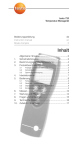
testo 922 Temperatur-Messgerät Bedienungsanleitung Instruction manual Mode d’emploi de en fr Inhalt 1. 2. 3. Allgemeine Hinweise ............................................2 Sicherheitshinweise ..............................................3 Bestimmungsgemäße Verwendung ......................4 Produktbeschreibung ..........................................5 3.1 3.2 3.3 4. 5. Inbetriebnahme ....................................................7 Bedienung............................................................8 5.1 5.2 5.3 5.4 6. 7. 8. 9. 10. Anzeige- und Bedienelemente ........................................5 Schnittstellen ..................................................................6 Spannungsversorgung ....................................................6 Fühler anschließen ..........................................................8 Gerät ein- / ausschalten ..................................................8 Displaybeleuchtung ein- / ausschalten ............................9 Einstellungen vornehmen ................................................9 Messen ..............................................................13 Wartung und Pflege............................................16 Fragen und Antworten........................................17 Technische Daten ..............................................18 Zubehör / Ersatzteile ..........................................19 2 Allgemeine Hinweise Allgemeine Hinweise Dieses Kapitel gibt wichtige Hinweise zur Nutzung der vorliegenden Dokumentation. Diese Dokumentation enthält Informationen, die für einen sicheren und effizienten Einsatz des Produkts beachtet werden müssen. Lesen Sie diese Dokumentation aufmerksam durch und machen Sie sich mit der Bedienung des Produkts vertraut, bevor Sie es einsetzen. Bewahren Sie dieses Dokument griffbereit auf, um bei Bedarf nachschlagen zu können. Kennzeichnungen Darstellung Bedeutung Bemerkungen ±, 1, 2 Hinweis Handlungsziel Voraussetzung i, 1, 2, ... (Handlungs-)Schritt Text - Displaytext Bedientaste Resultat º Querverweis Gibt hilfreiche Tipps und Informationen. Nennt das Ziel, welches durch nachfolgend beschriebene Handlungsschritte erreicht wird. Bei nummerierten Handlungszielen die vorgegebene Reihenfolge beachten! Voraussetzung muss erfüllt sein, damit eine Handlung wie beschrieben ausgeführt werden kann. Handlungsschritte ausführen. Bei nummerierten Handlungsschritten die vorgegebene Reihenfolge beachten! Text erscheint auf dem Gerätedisplay. Taste drücken. Nennt das Ergebnis eines vorangegangenen (Handlungs-)Schritts. Verweis auf weiterführende oder detailliertere Informationen. Taste Personenschäden / Sachschäden vermeiden i Mit dem Messgerät und Fühlern nicht an oder in der en fr Dieses Kapitel nennt allgemeine Regeln, die für einen sicheren Umgang mit dem Produkt unbedingt beachtet werden müssen. es Sicherheitshinweise it 1. de 1. Sicherheitshinweise 3 pt Nähe von spannungsführenden Teilen messen. i Das Messgerät / Fühler nie zusammen mit Lösungs- Daten vorgegebenen Parameter betreiben. i Das Messgerät nur sach- und bestimmungsgemäß verwenden. Keine Gewalt anwenden. i Handgriffe und Zuleitungen nicht Temperaturen über 70°C aussetzen, wenn diese nicht ausdrücklich für höhere Temperaturen zugelassen sind. Temperaturangaben auf Sonden / Fühlern beziehen sich nur auf den Messbereich der Sensorik. i Das Messgerät nur öffnen, wenn dies zu Wartungs- oder Instandhaltungszwecken ausdrücklich in der Dokumentation beschrieben ist. Nur Wartungs- und Instandsetzungsarbeiten durchführen, die in der Dokumentation beschrieben sind. Dabei die vorgegebenen Handlungsschritte einhalten. Aus Sicherheitsgründen nur OriginalErsatzteile von Testo verwenden. Fachgerecht entsorgen i Defekte Akkus / leere Batterien an den dafür vor- gesehenen Sammelstellen abgeben. i Produkt nach Ende der Nutzungszeit an Testo senden. Wir sorgen für eine umweltschonende Entsorgung. nl ?? i Das Messgerät nur innerhalb der in den Technischen ?? Produktsicherheit / Gewährleistungsansprüche wahren sv mitteln lagern, keine Trockenmittel verwenden. 4 2. Bestimmungsgemäße Verwendung 2. Bestimmungsgemäße Verwendung Dieses Kapitel nennt die Anwendungsbereiche, für die das Produkt bestimmt ist. Setzen Sie das Produkt nur für die Bereiche ein, für die es konzipiert wurde. Im Zweifelsfall bitte bei Testo nachfragen. Das testo 922 ist ein kompaktes Messgerät zur Messung von Temperaturen. Das Produkt wurde für folgende Aufgaben / Bereiche konzipiert: · HVAC-Bereich · Messung von Oberflächentemperaturen In folgenden Bereichen darf das Produkt nicht eingesetzt werden: · In explosionsgefährdeten Bereichen · Für diagnostische Messungen im medizinischen Bereich buchse(n) Display Bedientasten Funkmodulfach, Batteriefach, (Rückseite) Tastenfunktionen Taste Funktionen Gerät einschalten; Gerät ausschalten (gedrückt halten) Displaybeleuchtung ein-/ausschalten Messwert halten, Maximal-/Minimalwert anzeigen Konfigurationsmodus öffnen/verlassen (gedrückt halten) Im Konfigurationsmodus: Eingabe bestätigen Im Konfigurationsmodus: Option wählen, Wert erhöhen (für schnellen Durchlauf gedrückt halten) Daten drucken; Zyklisches Drucken (gedrückt halten) Messkanäle wechseln, die im Display angezeigt werden Zwischen der Anzeige von Temperatur und Differenz-Temperatur wechseln Im Konfigurationsmodus: Option wählen, Wert verringern (für schnellen Durchlauf gedrückt halten) en fr nl Infrarot-Schnittstelle, Fühler- ?? Übersicht sv pt 3.1 Anzeige- und Bedienelemente es Dieses Kapitel gibt eine Übersicht über die Komponenten des Produkts und deren Funktionen. it Produktbeschreibung ?? 3. de 3. Produktbeschreibung 5 6 3. Produktbeschreibung Wichtige Displayanzeigen Anzeige 1, 2, Bedeutung Batteriekapazität (links unten im Display): · Im Batteriesymbol leuchten 4 Segmente: Batterie des Geräts ist voll · Im Batteriesymbol leuchten keine Segmente: Batterie des Geräts ist fast leer Druckfunktion: Messwerte werden an den Drucker gesendet Zyklisches Drucken: Messwerte werden im eingestellten Zeitabstand an den Drucker gesendet Messkanal: Kanal 1, Kanal 2, Funkfühler (die Anzahl der angezeigten „Funkwellen“-Segmente zeigt die Signalstärke an) 3.2 Schnittstellen Infrarot-Schnittstelle Über die Infrarot-Schnittstelle an der Kopfseite des Geräts können Messdaten an einen Testo-Protokolldrucker gesendet werden. Fühlerbuchse(n) Über die Fühlerbuchse(n) an der Kopfseite des Geräts können steckbare Messfühler angeschlossen werden. Funkmodul (Zubehör) Funkfühler dürfen nur in Ländern verwendet werden, in denen sie zugelassen wurden (siehe Anwendungshinweise zum Funkfühler). Über das Funkmodul kann ein Funk-Messfühler angeschlossen werden. 3.3 Spannungsversorgung Die Spannungsversorgung erfolgt über eine 9V Blockbatterie (im Lieferumfang) bzw. -akku. Ein Netzbetrieb und das Laden eines Akkus im Gerät sind nicht möglich. 1 Batteriefach auf der Rückseite des Geräts öffnen: Batteriefachdeckel in Pfeilrichtung schieben und abnehmen. 2 Batterie / Akku (9V-Block) einlegen. Polung beachten! 3 Batteriefach schließen: Batteriefachdeckel aufsetzen und gegen die Pfeilrichtung schieben. - Das Gerät schaltet sich ein und der Konfigurationsmodus wird geöffnet. 4 Datum, Uhrzeit und Messeinheit einstellen. º Siehe Kapitel EINSTELLUNGEN VORNEHMEN, Handlungsziele DATUM /UHRZEIT EINSTELLEN und folgende. ² Funkmodul (Zubehör) einlegen: Funkfühler dürfen nur in Ländern verwendet werden, in denen sie zugelassen wurden (siehe Anwendungshinweise zum Funkfühler). Das Gerät ist ausgeschaltet. 1 Funkmodulfach auf der Rückseite des Geräts öffnen: Clip-Verschluss nach unten drücken und Funkmodulfach-Deckel abnehmen. 2 Funkmodul einlegen. 3 Funkmodulfach schließen: Funkmodulfach aufsetzen und schließen. en fr es it ² Batterie / Akku einlegen: pt i Schutzfolie vorsichtig abziehen. sv Schutzfolie entfernen: ² Display-S nl Dieses Kapitel beschreibt die Handlungsschritte, die zur Inbetriebnahme des Produkts erforderlich sind. ?? Inbetriebnahme ?? 4. de 4. Inbetriebnahme 7 8 5. Bedienung 5. Bedienung Dieses Kapitel beschreibt die Handlungsschritte, die beim Einsatz des Produkts häufig ausgeführt werden müssen. 5.1 Fühler anschließen Steckbare Fühler Steckbare Fühler müssen vor dem Einschalten des Messgeräts angeschlossen werden, damit diese vom Messgerät erkannt werden. i Anschlussstecker des Fühlers in die Fühlerbuchse des Messgeräts stecken. Funkfühler Funkfühler dürfen nur in Ländern verwendet werden, in denen sie zugelassen wurden (siehe Anwendungshinweise zum Funkfühler). Zur Verwendung von Funkfühlern ist ein Funkmodul erforderlich (Zubehör). Das Funkmodul muss vor dem Einschalten des Messgeräts angeschlossen werden, damit dieses vom Messgerät erkannt wird. Jeder Funkfühler besitzt eine Fühler-ID (Identifikationsnummer), diese muss im Konfigurationsmodus eingestellt werden. º Siehe Kapitel EINSTELLUNGEN VORNEHMEN. 5.2 Gerät ein-/ausschalten ² Gerät einschalten: i drücken. - Die Messansicht wird geöffnet: Der aktuelle Messwert wird angezeigt bzw. ---- leuchtet, wenn kein Messwert verfügbar ist. ² Displaybeleuchtung ein- / ausschalten: Das Gerät ist eingeschaltet. en drücken. Das Gerät ist eingeschaltet und befindet sich in der Messansicht. Hold, Max oder Min sind nicht aktiviert. i gedrückt halten (ca. 2s) bis die Anzeige im Display wechselt. Mit kann zur nächsten Funktion gewechselt werden. Der Konfigurationsmodus kann jederzeit verlassen werden. Dazu gedrückt halten (ca. 2s) bis das Gerät zur Messansicht gewechselt hat. Bereits durchgeführte Änderungen im Konfigurationsmodus werden dabei gespeichert. 2 Funkfühler anmelden: Funkfühler dürfen nur in Ländern verwendet werden, in denen sie zugelassen wurden (siehe Anwendungshinweise zum Funkfühler). Die Einstellfunktion für Funkfühler ist nur verfügbar, wenn ein Funkmodul (Zubehör) in das Messgerät eingelegt ist. º Siehe Kapitel INBETRIEBNAHME. Ist kein Funkmodul eingelegt: º Weiter mit Handlungsziel AUTO OFF EINSTELLEN. ?? 1 Konfigurationsmodus öffnen: ?? 5.4 Einstellungen vornehmen nl sv i fr 5.3 Displaybeleuchtung ein-/ausschalten es gedrückt halten (ca. 2s) bis die Display-Anzeige erlischt. it i pt ² Gerät ausschalten: de 5. Bedienung 9 10 5. Bedienung Jeder Funkfühler besitzt eine Fühler-ID (RF ID). Diese besteht aus den letzten 3 Ziffern der Serien-Nr. und der Position des Schiebeschalters im Funkfühler (H oder L). Der Konfigurationsmodus ist geöffnet und RF ID und Auto leuchten. Der Funkfühler ist eingeschaltet. 1 Mit die gewünschte Option wählen und mit bestätigen: · YES: Automatische Fühlererkennung einschalten (empfohlen). · no: Automatische Fühlererkennung ausschalten. no wurde gewählt: 2 Mit mit / die Fühler-ID manuell einstellen und bestätigen. YES wurde gewählt: - Die automatische Fühlererkennung wird gestartet. Auto blinkt, während das Gerät nach einem eingeschaltetem Funkfühler sucht. - Wenn ein Funkfühler gefunden wird, wird die Fühler-ID angezeigt. Wird kein Fühler gefunden, leuchtet NONE. Mögliche Ursachen für nicht gefundene Fühler: · Der Funkfühler ist nicht eingeschaltet oder die Batterie des Funkfühlers ist leer. · Der Funkfühler befindet sich außerhalb der Reichweite des Messgeräts. · Störquellen beeinflussen die Funkübertragung (z. B. Stahlbeton, Metallgegenstände, Wände oder andere Barrieren zwischen Empfänger und Sender, andere Sender gleicher Frequenz, starke elektromagnetische Felder). i Falls erforderlich: Mögliche Ursachen für die Störung der Funkübertragung beseitigen und automatische Fühlererkennung mit erneut starten. leuchtet. die gewünschte Option wählen und mit bestätigen: · On: Das Messgerät schaltet sich nach 10min ohne Tastenbetätigung automatisch aus. Ausnahme: Im Display wird ein festgehaltener Messwert angezeigt (Hold leuchtet) oder es werden gerade Messwerte zyklisch gedruckt ( leuchtet). · OFF: Das Messgerät schaltet nicht selbständig aus. i Mit 4 Max.- / Min.- Druckfunktion einstellen: Der Konfigurationsmodus ist geöffnet, MaxMin und leuchten. i Mit die gewünschte Option wählen und mit bestätigen. · On: Maximal- und Minimalwerte werden beim Drucken von aktuellen oder festgehaltenen Messwerten mit ausgedruckt. · OFF: Maximal- und Minimalwerte werden beim Drucken von aktuellen oder festgehaltenen Messwerten nicht mit ausgedruckt. 5 Zyklisches Drucken einstellen: Der Konfigurationsmodus ist geöffnet, Time und leuchten. i Mit / den Zeitabstand in Minuten einstellen, in dem Messwerte an den Drucker gesendet werden sollen und mit bestätigen. en fr es it pt Der Konfigurationsmodus ist geöffnet, Auto Off sv 3 Auto Off einstellen: nl oder aus dem Empfangsbereich entfernen und automatische Fühlererkennung mit erneut starten. 2 Mit zur nächsten Funktion wechseln. ?? i Falls erforderlich: Weitere Funkfühler ausschalten ?? - Befinden sich weitere Funkfühler im Empfangsbereich, wird eventuell die Fühler-ID eines anderen Funkfühlers angezeigt. de 5. Bedienung 11 12 5. Bedienung 6 Datum / Uhrzeit einstellen: Der Konfigurationsmodus ist geöffnet, Year leuchtet. 1 Mit / das aktuelle Jahr einstellen und mit bestätigen. 2 Mit / die weiteren Werte für Monat (Month), Tag (Day) und die Uhrzeit (Time) einstellen und jeweils mit bestätigen. 7 Einheit einstellen: Der Konfigurationsmodus ist geöffnet, °C oder °F blinkt. i Mit die gewünschte Einheit einstellen und mit bestätigen. 8 Reset durchführen: Der Konfigurationsmodus ist geöffnet, RESET leuchtet. i Mit die gewünschte Option wählen und mit bestätigen: · no: Keinen Reset durchführen. · Yes: Einen Reset durchgeführt. Dabei wird das Gerät auf die Werkseinstellungen zurückgesetzt. Ausgenommen vom Reset ist die Einstellung der Fühler-ID für den Funkfühler. - Das Gerät wechselt zurück zur Messansicht. 6. Messen 13 Das Gerät ist eingeschaltet und befindet sich in der fr Dieses Kapitel beschreibt die Handlungsschritte, die zur Durchführung von Messungen mit dem Produkt erforderlich sind. en de Messen es 6. Anzeige wechseln: ² Messkanal-A Abhängig von den aktiven Messkanälen, kann zwischen verschiedenen Anzeigekombinationen gewählt werden. ² Differenztemperatur anzeigen: Die Differenztemperatur zwischen 2 Messkanälen kann angezeigt werden. Die Messkanal-Anzeige wurde so eingestellt, dass die Messkanäle angezeigt werden, aus denen die Differenztemperatur errechnet werden soll. º siehe Handlungsziel MESSKANAL-ANZEIGE WECHSELN. 1 Differenztemperatur anzeigen: gedrückt halten, bis die Anzeige wechselt. 2 drücken um zurück zur Messansicht zu wechseln. ?? drücken. ?? i Anzeige wechseln: sv i Fühler positionieren und Messwerte ablesen. nl ² Messung durchführen: pt it Messansicht. 14 6. Messen ² Messwert halten, Maximal- / Minimalwert anzeigen: Der aktuelle Messwert kann festgehalten werden. Die Maximal- und Minimalwerte (seit dem letzten Einschalten des Geräts) können angezeigt werden. i mehrmals drücken, bis der gewünschte Wert angezeigt wird. - Es wird rollierend angezeigt: · Hold: festgehaltener Messwert · Max: Maximalwert · Min: Minimalwert · Aktueller Messwert ² Maximal- / Minimalwerte zurücksetzen: Die Maximal- / Minimalwerte aller Kanäle können auf den aktuellen Messwert zurückgesetzt werden. mehrmals drücken, bis Max oder Min leuchtet. 2 gedrückt halten. - Der angezeigte Wert blinkt 2mal. Alle Maximal- und Minimalwerte werden auf den aktuellen Messwert zurückgesetzt. 1 ² Messwerte drucken: Die im Display angezeigten Messwerte (aktueller Messwert, festgehaltener Messwert oder Max.- / Min.Wert) können ausgedruckt werden. Ein Testo-Protokolldrucker ist erforderlich (Zubehör). Bei eingeschalteter Max.- / Min.- Druckfunktion werden neben dem aktuellen Messwert bzw. dem festgehaltenen Messwert auch die Minimal- und Maximalwerte ausgedruckt. º Siehe Kapitel EINSTELLUNGEN VORNEHMEN. 1 Gerät so einstellen, dass der zu druckende Wert im Display angezeigt wird. 2 drücken. en fr es it pt Drucken wurde eingestellt. º Siehe Kapitel EINSTELLUNGEN VORNEHMEN. i gedrückt halten, bis leuchtet. i Zum Beenden des Zyklischen Druckens: drücken. sv Der gewünschte Zeitabstand für das Zyklische nl Ein Testo-Protokolldrucker ist erforderlich (Zubehör). ?? Die aktuellen Messwerte der im Display angezeigten Messkanäle können in einem festen Zeitabstand automatisch gedruckt werden. ?? ² Messwerte zyklisch drucken: de 6. Messen 15 16 7. Wartung und Pflege 7. Wartung und Pflege Dieses Kapitel beschreibt die Handlungsschritte, die zur Erhaltung der Funktionsfähigkeit und zur Verlängerung der Lebensdauer des Produkts beitragen. ± Gehäuse reinigen: i Das Gehäuse bei Verschmutzung mit einem feuchten Tuch (Seifenlauge) reinigen. Keine scharfen Reinigungs- oder Lösungsmittel verwenden! ± Batterie / Akku wechseln: Das Gerät ist ausgeschaltet. 1 Batteriefach auf der Rückseite des Gerätes öffnen: Batteriefachdeckel in Pfeilrichtung schieben und abnehmen. 2 Verbrauchte Batterie / leeren Akku herausnehmen und neue Batterie / neuen Akku (9V-Block) einlegen. Polung beachten! 3 Batteriefach schließen: Batteriefachdeckel aufsetzen und gegen die Pfeilrichtung schieben. War die Spannungsversorgung für längere Zeit unterbrochen, müssen Datum / Uhrzeit und Messeinheit neu eingestellt werden: - Das Gerät schaltet sich ein und der Konfigurationsmodus wird geöffnet. i Datum / Uhrzeit und Messeinheit einstellen. º Siehe Kapitel EINSTELLUNGEN VORNEHMEN, Handlungsziele DATUM /UHRZEIT EINSTELLEN und folgende. Anzeige: ----- · Fühlerbruch. Anzeige: uuuu Anzeige: oooo Anzeige: no Signal · Zulässiger Messbereich wurde unterschritten. · Zulässiger Messbereich wurde überschritten. · Angemeldeter Fühler wurde nicht gefunden. · Batterie wechseln · Gerät ausschalten, Fühler stecken und Gerät wieder einschalten. · Bitte kontaktieren Sie Ihren Händler oder den Testo-Kundendienst. · Zulässigen Messbereich einhalten. · Zulässigen Messbereich einhalten. · Fühler einschalten · Fühler in den Empfangsbereich bringen. · Funkfühler neu anmelden, siehe Kapitel Einstellungen vornehmen, Handlungsziel Funkfühler anmelden. Datum/Uhrzeit sind nicht mehr korrekt · Stromversorgung war für · Datum und Uhrzeit neu längere Zeit unterbrochen. einstellen. Falls wir Ihre Frage nicht beantworten konnten: Wenden Sie sich bitte an Ihren Händler oder den Testo-Kundendienst. Kontaktdaten finden Sie im Garantieheft oder im Internet unter www.testo.com. en fr es · Batterie des Geräts wechseln. · Batterie des Funkfühlers wechseln. · Funktion ausschalten it Mögliche Lösung · Batterie des Geräts ist fast leer. · Batterie des Funkfühlers ist fast leer. · Funktion Auto Off ist eingeschaltet. · Restkapazität der Batterie ist zu gering. · Fühler ist nicht gesteckt. pt Mögliche Ursachen leuchtet (links unten im Display). leuchtet (oberhalb des Symbols ). Gerät schaltet sich selbständig aus. sv Frage nl Dieses Kapitel gibt Antworten auf häufig gestellte Fragen. ?? Fragen und Antworten ?? 8. de 8. Fragen und Antworten 17 18 9. Technische Daten 9. Technische Daten Eigenschaft Werte Messgrößen Messbereich Auflösung Temperatur (°C/°F) -50.0...+1000°C / -58.0...+1832.0°F 0.1°C / 0.1°F (-50.0...+199.9°C / - 58.0...+391.8°F) 1°C / 1°F (restl. Bereich) (±0.5°C+0.3% v. Mw.) / (±0.9°F+0.3% v. Mw.) (-40.0...+900°C / -40.0...+1652°F) (±0.7°C+0.5% v. Mw.) / (±1.3°F+0.5% v. Mw.) (restl. Bereich) 2x Omega TE-Buchse für Temperaturfühler Typ K (NiCr-Ni), Funkmodul (Zubehör) 2/s -20 ... +50°C / -4 ... +122°F -40 ... +70°C / -40 ... +158°F 1x 9V Blockbatterie/-akku mit gestecktem Fühler: ca. 200h/ca. 68h, mit Funkfühler: ca. 45h/33h mit TopSafe (Zubehör) und gestecktem Fühler: IP65 89/336/EWG 2 Jahre Genauigkeit (±1 Digit) Fühleranschlüsse Messrate Betriebstemperatur Lagertemperatur Stromversorgung Standzeit (Displaybeleuchtung aus/an) Schutzart EG-Richtlinie Garantie 10. Zubehör / Ersatzteile 19 0554 0188 0554 0190 Funkfühler 1 Funk-Tauch-/Einstechfühler, NTC, Zulassung für z. B. DE, ES, IT, FR, GB Funk-Tauch-/Einstechfühler, NTC, Zulassung für z. B. USA en es Funkmodul 869.85MHz, Zulassung für z. B. DE, ES, IT, FR, GB Funkmodul 915.00MHz, Zulassung für z. B. USA fr Artikel-Nr. Funkmodule 1 0613 1001 0613 1002 it Bezeichnung de 10. Zubehör/Ersatzteile nl 0554 0191 0554 0222 0602 1293 0602 1993 0602 1793 Sonstiges TopSafe testo 922, schützt vor Stoß und Schmutz Testo Protokoll-Drucker mit IRDA- und Infrarot-Schnittstelle, 1 Rolle Thermopapier und 4 Mignonn-Batterien 1 0516 0222 0554 0547 Funkfühler dürfen nur in Ländern verwendet werden, in denen sie zugelassen wurden (siehe Anwendungshinweise zum Funkfühler). Eine vollständige Liste aller Zubehör- und Ersatzteile finden Sie in den Produktkatalogen und -broschüren oder im Internet unter: www.testo.com ?? 0602 0293 TE-Fühler Typ K Wasserdichter Tauch-/Einstechfühler, TE Typ K Wasserdichter Oberflächenfühler mit verbreiteter Messspitze für plane Oberflächen, TE Typ K Robuster Luftfühler, TE Typ K sv 0554 0189 ?? Funkhandgriff für steckbare Fühlerköpfe, inkl. TE-Adapter, Zulassung für z. B. DE, ES, IT, FR, GB Funkhandgriff für steckbare Fühlerköpfe, inkl. TE-Adapter, Zulassung für z. B. USA Adapter zum Anschluss von TE-Fühlern auf den Funkhandgriff TE-Fühlerkopf für Luft-/Tauch-Einstechmessung, steckbar auf den Funkhandgriff pt Universal-Funkhandgriff 20 Notizen testo 922 Temperature measuring instrument Bedienungsanleitung Instruction manual Mode d’emploi de en fr Content 1. 2. 3. General notes ....................................................22 Safety advice......................................................23 Intended purpose ..............................................24 Product description ............................................25 3.1 3.2 3.3 4. 5. Commissioning ..................................................27 Operation ..........................................................28 5.1 5.2 5.3 5.4 6. 7. 8. 9. 10. Display and control elements ........................................25 Interfaces ......................................................................26 Voltage supply ..............................................................26 Connect the probe ........................................................28 Switching the instrument on / off ..................................28 Switching the display light on / off ................................29 Performing settings ......................................................29 Measuring ..........................................................33 Care and maintenance ......................................36 Questions and answers ......................................37 Technical data ....................................................38 Accessories / Spare parts ..................................39 22 General notes General notes This chapter provides important advice on using this documentation. The documentation contains information that must be applied if the product is to be used safely and efficiently. Please read this documentation through carefully and familiarise yourself with the operation of the product before putting it to use. Keep this document to hand so that you can refer to it when necessary. Identification Representation Meaning ±, 1, 2 Note Objective Condition i, 1, 2, ... Step Text Display text Control button Result Cross-reference Button - º Comments Offers helpful tips and information. Denotes the objective that is to be achieved via the steps described. Where steps are numbered, you must always follow the order given! A condition that must be met if an action is to be carried out as described. Carry out steps. Where steps are numbered, you must always follow the order given! Text appears on the instrument display. Press the button. Denotes the result of a previous step. Refers to more extensive or detailed information. Avoid personal injury/damage to equipment i Do not use the instrument and probes to measure on or en fr This chapter gives the general rules which must be followed and observed if the product is to be handled safely. es Safety advice it 1. de 1. Safety advice 23 pt near live parts. i Never store the instrument/probes together with specified in the Technical data. i Always use the instrument properly and for its intended purpose. Do not use force. i Do not expose handles and feed lines to temperatures in excess of 70 °C unless they are expressly permitted for higher temperatures. Temperatures given on probes/sensors relate only to the measuring range of the sensors. i Open the instrument only when this is expressly described in the documentation for maintenance and repair purposes. Carry out only the maintenance and repair work that is described in the documentation. Follow the prescribed steps when doing so. For safety reasons, use only original spare parts from Testo. Ensure correct disposal i Take faulty rechargeable batteries/spent batteries to the collection points provided for them. i Send the product back to Testo at the end of its useful life. We will ensure that it is disposed of in an environmentally friendly manner. nl ?? i Operate the instrument only within the parameters ?? Product safety/preserving warranty claims sv solvents and do not use any dessicants. 24 1. Safety advice Instruments with radio module 915.00 MHz FSK Warning: Changes or modifications not expressly approved by the party responsible for compliance could void the user's authority to operate the equipment. This equipment has been tested and found to comply with the limits for a Class B digital device, pursuant to Part 15 of the FCC Rules. These limits are designed to provide reasonable protection against harmful interference in a residential installation. This equipment generates, uses and can radiate radio frequency energy and, if not installed and used in accordance with the instructions, may cause harmful interference to radio communications. However, there is no guarantee that interference will not occur in a particular installation. If this equipment does cause harmful interference to radio or television reception, which can be determined by turning the equipment off and on, the user is encouraged to try to correct the interference by one or more of the following measures: · Reorient or relocate the receiving antenna. · Increase the separation between the equipment and receiver. · Connect the equipment into an outlet on a circuit different from that to which the receiver is needed. · Consult the dealer or an experienced radio/TV technician for help. Operation is subject to the following two conditions: · this device may not cause harmful interference, and · this device must accept any interference received, including interference that may cause undesired operation. 2. Intended purpose This chapter gives the areas of application for which the product is intended. Use the product only for those applications for which it was designed. Ask Testo if you are in any doubt. testo 922 is a compact measuring instrument for measuring temperatures. The product was designed for the following tasks/applications: · HVAC applications · Measuring surface temperatures The product should not be used in the following areas: · Areas at risk of explosion · Diagnostic measurements for medical purposes compartment (rear) Key functions Key Functions Switch instrument on; switch instrument off (press and hold) Switch display light on / off Keep reading, display maximum/minimum value Open/leave configuration mode (press and hold) In configuration mode: Confirm input In configuration mode: Select option, increase value (press and hold to increase values rapidly) Print data; cyclical printing (press and hold) Change measurement channels that are shown on the display Change between displaying temperature and differential temperature In configuration mode: Select option, decrease value (press and hold to decrease values rapidly) en fr nl Infrared interface, probe socket(s) Display Control buttons Radio module compartment, battery ?? Overview sv pt 3.1 Display and control elements es This chapter provides an overview of the components of the product and their functions. it Product description ?? 3. de 3. Product description 25 26 3. Product description Important displays Display 1, 2, Meaning Battery capacity (bottom left in display): 4 segments in the battery symbol are lit: Instrument battery is fully charged · No segments in the battery symbol are lit: Battery is almost spent Print function: Readings are sent to the printer Cyclical printing: Readings are sent to the printer at set intervals of time Measurement channel: Channel 1, channel 2, radio probe (the number of “radio wave” segments shown indicates the strength of the signal) 3.2 Interfaces Infrared interface Measurement data can be sent to a Testo printer via the infrared interface on the head of the instrument. Sensor socket(s) Plug-in measuring probes can be connected via the probe socket(s) on the head of the instrument. Radio module (accessory part) Radio probes may only be used in countries in which they have been Type Approved (see application information of the radio probe). A radio measuring probe can be connected via the radio module. 3.3 Voltage supply Voltage is supplied by means of a 9 V monobloc battery (included in delivery) or rechargeable battery. It is not possible to run the instrument from the mains supply or charge a rechargeable battery in the instrument. 1 To open the battery compartment on the rear of the instrument, push the lid of the battery compartment in the direction of the arrow and remove. 2 Insert a battery/rechargeable battery (9 V monobloc). Observe the polarity! 3 To close the battery compartment, replace the lid of the battery compartment and push it against the direction of the arrow. - The instrument switches itself on and configuration mode is opened. 4 Set the date, time and unit of measurement. º See the chapter PERFORMING SETTINGS, objectives SETTING THE DATE/TIME and following. ² Inserting a radio module (accessory part): Radio probes may only be used in countries in which they have been Type Approved (see application information of the radio probe). The instrument is switched off. 1 To open the radio module compartment on the rear of the instrument, push the clip lock downwards and remove the lid of the radio module compartment. 2 Insert the radio module. 3 To close the radio module compartment, replace the radio module compartment and close it. en fr es it ² Inserting a battery/rechargeable battery: pt i Pull the protective film off carefully. sv ² Removing the protective film on the display: nl This chapter describes the steps required to commission the product. ?? Commissioning ?? 4. de 4. Commissioning 27 28 5. Operation 5. Operation This chapter describes the steps that have to be executed frequently when using the product. 5.1 Connect the probe Plug-in probes Plug-in probes must be connected before the measuring instrument is switched on so that they are recognised by the instrument. i Insert the connector of the probe into the probe socket. Radio probes Radio probes may only be used in countries in which they have been Type Approved (see application information of the radio probe). A radio module (accessory part) is required for the use of radio probes. The radio module must be connected before the measuring instrument is switched on so that it is recognised by the instrument. Each radio probe has a probe ID (identification number). This must be set in configuration mode. º See the chapter PERFORMING SETTINGS. 5.2 Switching the instrument on / off ² Switching the instrument on: i Press . - Measurement view is opened: The current reading is displayed, or ---- lights up if no reading is available. ² Switching the instrument off: i Press and hold (for approx. 2s) until the display The instrument is switched on. es . The instrument is switched on and is in measurement view. Hold, Max or Min are not activated. i Press and hold (for approx. 2s) until the display changes. You can change to the next function with . You can leave configuration mode at any time. To do so, press and hold (for approx. 2s) until the instrument has changed to measurement view. Any changes that have already been made in configuration mode will be saved. 2 To register the radio probe: Radio probes may only be used in countries in which they have been Type Approved (see application information of the radio probe). The setting function for radio probes is only available if a radio module (accessory part) is inserted into the measuring instrument. º See the chapter COMMISSIONING. If no radio module is inserted: º Continue with objective TO SET AUTO OFF. ?? 1 To open configuration mode: ?? 5.4 Performing settings nl sv i Press it ² Switching the display light on / off: pt 5.3 Switching the display light on / off fr en goes out de 5. Operation 29 30 5. Operation Each radio probe has a probe ID (RF ID). This consists of the last 3 digits of the serial no. and the position of the slide switch in the radio probe (H or L). Configuration mode is opened and RF ID and Auto are lit. The radio probe is switched on. 1 Select the desired option with and confirm with : · YES: Switches automatic probe detection on (recommended). · no: Switches automatic probe detection off. no was selected: 2 Use / confirm with to set the probe ID manually and . YES was selected: - Automatic probe detection is started. Auto flashes while the instrument looks for a radio probe that is switched on. - Once a radio probe is found, the probe ID is displayed. If no probe is found, NONE lights up. Possible reasons why probes are not found: · The radio probe is not switched on or the battery of the radio probe is spent. · The radio probe is outside the range of the measuring instrument. · Sources of interference are influencing the radio transmission (e.g. reinforced concrete, metal objects, walls or other barriers between transmitter and receiver, other transmitters of the same frequency, strong electromagnetic fields). i If necessary, rectify the possible causes for the disruption to the radio transmission and start automatic probe detection again with . remove from the reception range, and start automatic probe detection again with . 2 Press to change to the next function. en it 3 To set Auto Off: fr i If necessary: switch off other wireless probes or es If further wireless probes are within reception range, the probe ID of a different wireless probe may be displayed. de 5. Operation 31 4 To set the max./min.print function: Configuration mode is opened, MaxMin and i Select the desired option with are lit. and confirm with . · On: Maximum and minimum values are printed out as well when current or recorded readings are printed. · OFF: Maximum and minimum values are not printed out as well when current or recorded readings are printed. 5 To set cyclical printing: Configuration mode is opened, Time and are lit. i Use / to set the time interval (in minutes) at which the readings are to be sent to the printer and confirm with . sv nl ?? and confirm with : · On: The measuring instrument switches off automatically if no button is pressed for 10 min. Exception: A recorded reading is shown on the display (Hold is lit) or readings are being printed cyclically ( lit). · OFF: The measuring instrument does not switch itself off automatically. ?? i Select the desired option with pt Configuration mode is opened, Auto Off is lit. 32 5. Operation 6 To set the date/time: Configuration mode is opened, Year is lit. 1 Use / to set the current year and confirm with . 2 Use / to set the other values for the month (Month), day (Day) and time (Time) and confirm each one with . 7 To set the unit of measurement: Configuration mode is opened, °C or °F flashes. i Select the desired unit of measurement with confirm with and . 8 To reset: Configuration mode is opened, RESET is lit. i Select the desired option with and confirm with : · no: Instrument is not reset. · Yes: Instrument is reset. The instrument is reset to the factory settings. The setting of the probe ID for the radio probe is not reset. - The instrument returns to measurement view. 6. Measuring 33 The instrument is switched on and is in measurement view. it ² Taking a measurement: fr This chapter describes the steps that are required to perform measurements with the product. en de Measuring es 6. ² Displaying the differential temperature: The differential temperature between 2 measurement channels can be displayed. The measurement channel display was configured so that the measurement channels from which the differential temperature is to be calculated are displayed. º see objective CHANGING THE MEASUREMENT CHANNEL DISPLAY. 1 To display the differential temperature: press and hold until the display changes. 2 Press to change back to measurement view. ?? . ?? i To change the display: Press sv You can choose between a variety of display combinations, depending on which measurement channels are active. nl ² Changing the measurement channel display: pt i Put the probe in position and read off the readings. 34 6. Measuring ² Holding the reading, displaying the maximum/minimum value: The current reading can be recorded. The maximum and minimum values (since the instrument was last switched on) can be displayed. i Press several times until the desired value is displayed. - The following are displayed in turn: · Hold: the recorded reading · Max: Maximum value · Min: Minimum value · The current reading ² Resetting the maximum/minimum values: The maximum/minimum values of all channels can be reset to the current reading. This function is not available if the Auto Hold function is switched on. 1 Press several times until Max or Min lights up. . - The displayed value flashes twice. All maximum and minimum values are reset to the current reading 2 Press and hold ² Printing readings: The readings shown on the display (current reading, recorded reading or max./min. reading) can be printed out. A Testo printer is required (accessory part). With the Max./Min. print function switched on, the maximum and minimum values are printed out as well as the current reading or recorded reading. º See the chapter PERFORMING SETTINGS. 1 Configure the instrument so that the value to be printed is shown on the display. 2 Press . en fr es it pt been set. º See the chapter PERFORMING SETTINGS. i Press and hold until lights up. i To end cyclical printing: Press . sv The desired interval of time for cyclical printing has nl A Testo printer is required (accessory part). ?? The current readings of the measurement channels shown on the display can be printed out automatically at a fixed interval of time. ?? ² Printing readings cyclically: de 6. Measuring 35 36 7. Care and maintenance 7. Care and maintenance This chapter describes the steps that help to maintain the functionality of the product and extend its service life. ± Cleaning the housing: i Clean the housing with a moist cloth (soap suds) if it is dirty. Do not use aggressive cleaning agents or solvents! ± Changing the battery/rechargeable battery: The instrument is switched off. 1 To open the battery compartment on the rear of the instrument, push the lid of the compartment in the direction of the arrow and remove it. 2 Remove the spent battery/rechargeable battery and insert a new battery/rechargeable battery (9 V monobloc). Observe the polarity! 3 To close the battery compartment, replace the lid of the compartment in position and push it against the direction of the arrow. If the voltage supply had been interrupted for a long period, the date/time and unit of measurement will have to be reset: - The instrument switches itself on and configuration mode is opened. i Set the date/time and unit of measurement. º See the chapter PERFORMING SETTINGS, objectives SETTING THE DATE/TIME and following. en Questions and answers fr 8. de 8. Questions and answers 37 Display: ----- Display: uuuu Display: oooo· Display: no Signal Date/time are no longer correct · Replace battery · Switch instrument off, connect probe and switch instrument back on again. · Sensor break. · Please contact your dealer or Testo Customer Service. · Permitted measuring range · Keep to permitted was undershot. measuring range. Permitted measuring range · Keep to permitted was exceeded. measuring range. · Registered probe · Switch on probe. was not found. · Bring probe into reception range. · Register radio probe again, see chapter PERFORMING SETTINGS, objective TO REGISTER THE RADIO PROBE. · Voltage supply was · Reset date and time. interrupted for a longer time If we are unable to answer your question, please contact your dealer or Testo Customer Service. Contact details can be found on the guarantee card or on the Internet under www.testo.com. it pt sv · Replace instrument battery. · Replace radio probe battery. Switch function off. nl Possible solution · Instrument battery is almost spent. · Radio probe battery is almost spent. · Auto Off function is switched on. · Residual capacity of battery is too low. · Sensor is not plugged in. ?? Possible causes is lit (bottom left in display). is lit (above symbol). Instrument switches itself off. ?? Question es This chapter gives answers to frequently asked questions. 38 9. Technical data 9. Characteristic Parameters Meas. range Resolution Technical data Value Temperature (°C/°F) -50.0...+1000°C / -58.0...+1832.0°F 0.1°C / 0.1°F (-50.0...+199.9°C / - 58.0...+391.8°F) 1°C / 1°F (rest of range) Accuracy (±0.5°C+0.3% of reading) / (±0.9°F+0.3% of reading) (±1 Digit) (-40.0...+900°C / -40.0...+1652°F) (±0.7°C+0.5% of reading) / (±1.3°F+0.5% of reading) (rest of range) Sensor connections 2x Omega TC socket for temperature probe type K (NiCr-Ni), radio module (accessory part) Measuring rate 2/s Operating temperature range -20 ... +50°C / -4 ... +122°F Storage temperature -40 ... +70°C / -40 ... +158°F Voltage supply 1x 9 V monobloc battery/rech. battery Running time (display with probe connected: approx. 200h / approx. 68h, lighting off / on) with radio probe: approx. 45h / 33h Protection class with TopSafe (accessory part) and probe connected: IP65 EC Directive 89/336/EEC Warranty 2 years 10. Accessories / Spare parts 39 fr en de 10. Accessories / Spare parts Part no. Radio modules 1 Radio probes 1 0613 1001 0613 1002 0554 0189 0554 0191 0554 0222 0602 0293 TC probes, type K Water-proof immersion/penetration probe, TC type K Water-proof surface probe with widened measurement tip for smooth surfaces, TC type K Robust air probe, TC type K 0602 1293 0602 1993 0602 1793 Miscellaneous TopSafe testo 922, protects from impact and dirt particles Testo printer with IRDA and infrared interface, 1 roll thermal paper and 4 round cell batteries 1 0516 0222 0554 0547 Radio probes may only be used in countries in which they have been Type Approved (see application information of the radio probe). For a complete list of all accessories and spare parts, please refer to the product catalogues and brochures or look up the www.testo.com Internet site. nl Radio handle for plug-in probeheads incl. TC adapter, authorisation for e. g. DE, ES, IT, FR, GB Radio handle for plug-in probeheads incl. TC adapter, authorisation for e. g. USA Adapter for connection to TC probes on radio handle TC -probehead for air/immersion tip, attachable to radio handle sv Universal radio handles ?? Radio immersion/penetration probe, NTC, authorisation for e. g. DE, ES, IT, FR, GB Radio immersion/penetration probe, NTC, authorisation for e. g. USA pt it 0554 0188 0554 0190 ?? Radio module 869.85MHz, authorisation for e. g. DE, ES, IT, FR, GB Radio module 915.00MHz, authorisation for e. g. USA es Name 40 Notes testo 922 Appareil de mesure de température Bedienungsanleitung Instruction manual Mode d’emploi de en fr Sommaire 1. 2. 3. Recommandations générales ............................42 Consignes de sécurité........................................43 Utilisation conforme à l’application......................44 Description du produit ........................................45 3.1 3.2 3.3 4. 5. Mise en service ..................................................47 Utilisation ..........................................................48 5.1 5.2 5.3 5.4 6. 7. 8. 9. 10. Eléments d'affichage et de commande ........................45 Interfaces ......................................................................46 Alimentation ..................................................................46 Raccorder la sonde ......................................................48 Allumer/éteindre l'appareil ............................................48 Allumer/éteindre l'éclairage de l'écran ..........................49 Paramétrage ................................................................49 Mesures ............................................................53 Maintenance et entretien ....................................55 Questions et réponses ......................................56 Caractéristiques techniques ..............................57 Accessoires........................................................58 42 Recommandations générales Recommandations générales Ce chapitre donne des recommandations générales pour l'utilisation de ce document. Ce document comporte des informations devant être prises en compte pour une utilisation efficace du produit en toute sécurité. Veuillez, attentivement, prendre connaissance de ce document et familiarisez-vous avec le maniement du produit avant de l'utiliser. Conservez-le à portée de main afin de pouvoir y recourir en cas de besoin. Caractéristiques Symboles Signification Indication ±, 1, 2 i, 1, 2, ... Texte Taste - º Observations Fournit des astuces et une aide efficace Objectif de la Indique l'objectif devant être atteint par les manipulations décrites par la suite. En cas de numérotation des manipulations, respectez l'ordre indiqué ! Condition La condition doit être remplie afin que la manipulation décrite puisse être réalisée. Etape (de la manipulation) Réalisez les étapes de la manipulation. En cas d'étapes numérotées, respectez l'ordre indiqué ! Texte affiché Le texte apparaît sur l'affichage de l'appareil. Touche de fonction Appuyez sur la touche Résultat Désigne le résultat d'une étape (précédente) d'une manipulation. Observation Observation relative à une information détaillée ou supplémentaire. ou avec les capteurs sur ou à proximité d'éléments conducteurs. i Ne stockez jamais l'appareil/les cellules de mesure conjointement avec des solvants, n'utilisez pas de dessicateur. Assurer la sécurité du produit/Conserver le droit à la garantie en fr es i Ne réalisez pas de mesures avec l'appareil de mesure it Eviter les dommages matériels/corporels pt Ce chapitre fournit des règles générales devant absolument être respectées pour manier l'appareil en toute sécurité. sv Consignes de sécurité nl 1. de 1. Consignes de sécurité 43 Elimination selon les règles de l'art i Déposez les accus défectueux/les piles vides aux endroits prévus à cet effet. (Collecteur de piles) i Renvoyez le produit chez Testo au terme de sa durée d'utilisation. Nous assurons une élimination respectueuse de l'environnement. ?? la limite des paramètres décrits dans les caractéristiques techniques. i Utilisez l'appareil de mesure en fonction de sa vocation. Ne faites pas usage de la force. i Ne soumettez pas les poignées ni les éléments de raccordements à des températures supérieures à 70° C, si ceux-ci ne sont pas expressément prévus pour des températures supérieures. Les indications de température des capteurs/sondes ne sont basées que sur l'étendue de mesure de capteurs, pas des composants de la poignée. i Ouvrez l'appareil de mesure que si ceci est expressément décrit dans la notice d’utilisation, dans le but de réaliser de l'entretien ou de la maintenance. Respectez les étapes indiquées. Pour des raisons de sécurité, n'utilisez que des pièces de rechange originales testo. ?? i Faites fonctionner l'appareil de mesure uniquement dans 44 1. Consignes de sécurité Appareils avec module radio, sondes radio 915.00 MHz FSK Attention: Tout changement ou modification non expressément approuvé par les autorités responsables de la conformité peut annuler le droit de l'utilisateur à l'emploi de l'équipement en question. Remarque-1: Cet équipement a été testé et trouvé conforme aux limites des dispositifs numériques de classe B définies par l’alinéa 15 du règlement de la FCC. Ces limites sont conçues pour fournir une protection raisonnable contre les interférences nocives quand l’équipement est utilisé dans un environnement résidentiel. Cet équipement crée, utilise et peut émettre de l’énergie de fréquence radio et peut, s’il n’est pas installé et utilisé suivant les instructions du manuel du fabricant, être la cause d’interférences avec la réception radio et de télévision. Il n’y a cependant aucune garantie que l’interférence ne va pas se reproduire dans une installation particulière. Si l’équipement crée des interférences nocives pour la réception radio et de télévision, ce qui peut être déterminé en l’allumant et l’éteignant, vous êtes encouragé à essayer de corriger les interférences en prenant une ou plusieurs des mesures suivantes: · Changez l’orientation de l’antenne de réception ou déplacez-la. · Augmentez la distance entre le récepteur et l’équipement. · Branchez l’équipement et le récepteur dans des prises de circuits différents. · Consultez votre fournisseur ou un technicien expérimenté en radio/télévision pour de l’aide supplémentaire. Remarque-2: Utilisation est soumise aux deux conditions suivantes: · Cet appareil ne doit pas créer d'interférences nocives · Cet appareil doit accepter toutes les interférences qu'il reçoit, y compris celles qui peuvent gêner son fonctionnement. 2. Utilisation conforme à l’application Ce chapitre comporte les domaines d'utilisation pour lesquels le produit est destiné. Utilisez le produit que dans les domaines pour lesquels il est conçu. En cas de doute, vérifiez auprès de Testo. Le testo 926 est un appareil de mesure compact pour la mesure de température. Le produit a été conçu pour les tâches/domaines suivants : · Domaine alimentaire · Domaine laboratoires, pharma., chimie, cosmétique Le produit ne doit pas être utilisé dans les domaines suivants: · dans les milieux explosifs · pour les mesures de diagnostics dans le domaine médical compartiment pile, (verso) Fonctions des touches Touche Fonctions Allumer l'appareil; Eteindre l'appareil (maintenir appuyé) Allumer/éteindre l'éclairage de l'affichage (impulsion brève) Conserver une donnée de mesure, afficher valeurs max/min Ouvrir/quitter mode de configuration (Maintenir appuyé) En mode configuration : Confirmer la saisie En mode configuration : Sélectionner l'option, changer la valeur (Maintenir appuyé pour un déroulement rapide) Imprimer les données ; impression cyclique (maintenir appuyé) Passer de l'affichage du capteur raccordé au capteur radio ( liaison allumée) Passer de l'affichage de la température à la température différentielle En mode configuration : Sélectionner l'option, changer la valeur (pour un déroulement rapide maintenir appuyé) en fr nl Interface série, douille pour capteur(s) Affichage Touche de fonction Compartiment module radio, ?? Aperçu sv pt 3.1 Eléments d'affichage et de commande es Ce chapitre fournit un aperçu des composants du produit et de ses fonctions. it Description du produit ?? 3. de 3. Description du produit 45 46 3. Description du produit Eléments importants de l’affichage Affichage 1, 2, Significations Capacité de batterie (partie inférieure gauche de l'affichage): · 4 segments sont affichés dans le symbole de la pile : la pile est en pleine charge · Aucun segment n'apparaît dans le symbole de la pile : la pile de l'appareil est quasiment vide Fonction Imprimer : les données de mesure sont envoyées à l'imprimante. Impression cyclique : les données de mesure sont envoyées dans un intervalle de temps paramétrable vers l'imprimante Capteur radio : canal 1, canal 2, capteur de télémesure (le nombre des segments d'émission affichés indique la force du signal) 3.2 Interfaces Interface infrarouge L'interface infrarouge, dans la partie supérieure de l'appareil, permet d'envoyer les données de mesure vers l'imprimante testo. Connecteurs Les connecteurs sur la partie supérieure de l'appareil permettent de raccorder des sondes de mesure. Module radio (accessoires) Les sondes radio ne doivent être utilisées que dans les pays pour lesquelles leurs fréquences sont homologuées (voir complément d'information pour sonde telémesure). Le module radio permet de raccorder un capteur radio. 3.3 Alimentation L'alimentation électrique est réalisée par un pile de 9V, (compris dans la livraison) voire d'un accu. Il n'est pas possible de raccorder l'appareil sur secteur, ni de charger l'accu dans l'appareil. ² Enlevez le film de protection sur l'afficheur : i Retirez soigneusement le film de protection de l’afficheur. en fr Ce chapitre décrit les étapes nécessaires à la mise en service du produit. es Mise en service it 4. de 4. Mise en service 47 pt Faites glisser le couvercle du compartiment pile dans le sens de la flèche puis retirez-le. 2 Insérez la pile/l'accu (9V). Respectez la polarité ! 3 Fermez le compartiment pile : Repositionnez le couvercle du compartiment pile et faites glisser dans le sens opposé de la flèche. - L'appareil démarre et le mode configuration s'ouvre. 4 Paramétrez la date, l'heure et l'unité de mesure. º Cf. chapitre REALISER LE PARAMETRAGE, les étapes PARAMETRAGE DE LA DATE/DE L’HEURE et suivants. ² Insérer module radio (accessoires): Les sondes radio ne doivent être utilisées que dans les pays pour lesquelles leurs fréquences sont homologuées (voir complément d'information pour sonde radio). L’appareil est éteint. 1 Ouvrez le compartiment module radio au dos de l'appareil : Poussez le clip de fermeture vers le bas et retirez le couvercle du module radio. 2 Insérez le module radio 3 Fermez le module radio: Positionnez le module radio et fermez. ?? nl sv 1 Ouvrez le compartiment pile au dos de l'appareil : ?? ² Insérez la pile/l'accu: 48 5. Utilisation 5. Utilisation Ce chapitre décrit les manipulations devant souvent être effectuées lors de l'utilisation du produit. 5.1 Raccorder la sonde Sondes avec connecteur Les sondes avec connecteurs doivent être raccordées avant d'allumer l'appareil afin qu'elles puissent être reconnues par l'appareil de mesure. i Raccordez la fiche de la sonde sur l'appareil de mesure. Sonde radio Les sondes Telémesure ne doivent être utilisées que dans les pays pour lesquelles leurs fréquences sont homologuées (voir complément d'information pour sonde radio). Un module radio est nécessaire pour utiliser des sondes radio (accessoires). Le module radio doit être raccordé avant d'allumer l'appareil, afin qu'il puisse être reconnu par l'appareil de mesure. Chaque sonde radio dispose d'un ID-sonde (N° d'identification), celui-ci doit être paramétré dans le mode configuration. º Cf. chapitre PARAMETRAGE. 5.2 Allumer/éteindre l'appareil ² Allumer l'appareil: i Appuyez sur - L'aperçu s'ouvre : La valeur de mesure actuelle est affichée ou ---- apparaît, si aucune valeur de mesure n'est disponible. ² Allumer/éteindre l'éclairage de l'écran: L'appareil est allumé. . 1 Ouvrir le mode configuration: en fr ?? 5.4 Paramétrage nl sv i Appuyez sur es 5.3 Allumer/éteindre l'éclairage de l'écran it l'affichage s'éteigne. pt ² Eteindre l'appareil: i Maintenez appuyé (env. 2 s) jusqu'à ce que de 5. Utilisation 49 mesure. Hold, Max ou Min ne sont pas activés. appuyé (env. 2 s) jusqu'à ce que l'affichage change. i Maintenez Il est possible de passer à la fonction suivante avec la touche . Il est possible de quitter le mode configuration à tout instant. Pour ce faire, maintenez la touche appuyée (env. 2 s) jusqu'à ce que l'appareil passe en mode aperçu. Les modifications déjà entreprises dans le mode configuration sont alors sauvegardées. 2 Enregistrer la sonde radio: Les sondes Telémesure ne doivent être utilisées que dans les pays pour lesquelles leurs fréquences sont homologuées (voir complément d'information pour sonde radio). La fonction paramétrage de la sonde radio n'est disponible que lorsqu'un module radio (accessoires) est inséré dans l'appareil de mesure. º cf. Chapitre MISE EN SERVICE. Si aucun module radio n'est inséré: º Etape suivante avec PARAMETRER AUTO OFF. ?? L'appareil est allumé et il est en mode aperçu de 50 5. Utilisation Chaque sonde radio dispose d'un ID-sonde (RF ID). Celui-ci est composé des 3 derniers chiffres de la référence de l'article et de la position du commutateur de la sonde radio (H ou L). Le mode configuration est ouvert et RF ID ou Auto s'affiche. La sonde radio s'allume. 1 Sélectionnez l'option souhaitée avec et validez avec : · YES: Allumez la détection automatique (recommandé). · NO: Eteignez la détection automatique. NO a été sélectionné: 2 Paramétrez manuellement l'ID-sonde avec / et validez avec . YES a été sélectionné: - La reconnaissance automatique de la sonde démarre. Auto clignote, pendant que l'appareil recherche une sonde radio allumée. - Lorsqu'une sonde radio est trouvée, l'ID de la sonde est affiché. Si aucune sonde n'est trouvée NONE s'allume. Possibles origines de sondes non trouvées : · La sonde radio n'est pas allumée ou la pile de la sonde radio est vide. · La sonde radio se trouve hors de la portée de l'appareil de mesure. · Des sources parasites gênent la transmission (par ex. Béton armé, éléments métalliques, murs ou d'autres barrières entre récepteur et émetteur, d'autres émetteurs de même fréquence, de forts champs électromagnétiques). i Si nécessaire : éliminez les causes possibles gênant la transmission et redémarrez la reconnaissance automatique de sonde avec . 2 Passez à la fonction suivante avec . Le mode configuration s'ouvre, Max/Min et apparaissent. i Sélectionnez l'option souhaitée avec et validez avec . · On: Les valeurs maximales et minimales sont imprimées lors de l'impression de valeurs de mesure actuelles ou conservées. · OFF: Les valeurs maximales et minimales ne sont pas imprimées lors de l'impression de valeurs de mesure actuelles ou conservées. 5 Paramétrer l'impression cyclique: Le mode configuration s'ouvre, Time et apparaissent. i Paramétrez l'intervalle en minutes avec / intervalle auquel les valeurs mesurées sont envoyées vers l'imprimante et validez avec . 6 Paramétrer la date/l'heure: Le mode configuration s'ouvre, Year apparaît. 1 Paramétrez l'année en cours avec / et validez avec . 2 Avec / , paramétrez les données suivantes concernant le mois (Month), le jour (Day) et l'heure (Time) et validez respectivement avec . en fr es it pt sv 4 Paramétrer Fonction impression Max/Min: nl avec : · On: L'appareil de mesure s'éteint automatiquement après 10 mn de non activation de touche. Exception : une valeur de mesure maintenue affichée (Hold apparaît) ou des données de mesures sont juste en train d'être imprimées de manière cyclique. ( apparaît). · OFF: L'appareil de mesure ne se coupe pas automatiquement. ?? Le mode configuration est ouvert, Auto Off est allumé. i Sélectionnez l'option souhaitée avec et validez ?? 3 Paramétrer Auto Off: de 5. Utilisation 51 52 6. Mesures 7 Paramétrer l'unité: Le mode configuration s'ouvre, °C ou °F clignotent. i Paramétrez l'unité souhaitée avec et validez avec . 8 Réaliser un Reset: Le mode configuration s'ouvre. RESET apparaît. i Sélectionnez l'option choisie avec et validez avec : · no: Ne pas réaliser de Reset. · Yes: Réaliser un Reset. L'appareil repasse alors en paramétrage d'usine. Le Reset ne comprend pas le paramétrage de l'ID-sonde pour la sonde radio. - L'appareil repasse en aperçu. 6. Mesures 53 i Positionnez la sonde et lisez les valeurs mesurées. ² Changer d'affichage de canal de mesure: En fonction des canaux de mesure actifs, il est possible de choisir entre différentes combinaisons d'affichage. i Changer d'affichage: Appuyez sur fr es it ² Réaliser des mesures: pt L'appareil est allumé et se trouve en mode aperçu. sv Ce chapitre décrit les étapes nécessaires à réaliser des mesures avec ce produit. en de Mesures . Les appareils sont capables de mesurer le Delta T entre deux canaux. ?? La température différentielle a été paramétrée de telle ?? ² Afficher la température différentielle : nl 6. façon à afficher les canaux de mesure à partir desquels il est possible de la calculer. º cf. Etape CHANGER D’AFFICHAGE CANAL DE MESURE. 1 Afficher la température différentielle : Maintenez appuyé jusqu'à ce que l'affichage bascule. 2 Appuyez sur pour rebasculer en aperçu de mesure. ² Conserver les valeurs mesurées, afficher les valeurs Max/Min: La valeur mesurée actuelle peut être conservée. Les valeurs maximales et minimales (depuis la dernière mise en route de l'appareil) peuvent être affichées. i Appuyez plusieurs fois sur , jusqu'à ce que la valeur souhaitée soit affichée. - L'affichage alternatif se fait de la façon suivante: · Hold: Valeur figée · Max: Valeur maximale · Min: Valeur minimale · Valeur actuelle 54 6. Mesures ² Recalage des valeurs minimales et maximales: Les valeurs maximales et minimales de tous les canaux peuvent être recalées par rapport à une valeur mesurée actuelle. 1 Appuyez plusieurs fois sur jusqu'à ce que Max ou Min apparaissent. 2 Maintenez appuyé. - La valeur affichée clignote 2 fois. Toutes les valeurs maximales/minimales sont recalées à la valeur actuelle. ² Imprimer les valeurs mesurées: Les valeurs mesurées affichées (valeur de mesure actuelle, valeur de mesure figée ou valeur Max/Min) peuvent être imprimées. Une imprimante testo est nécessaire à cela (accessoires). Lorsque Impression Max/Min est en fonction, les valeurs minimales/maximales sont imprimées en plus de la valeur mesurée actuelle ou de la valeur figée. º Cf. Chapitre PARAMETRAGE. 1 Paramétrez l'appareil de sorte que la valeur à 2 imprimer soit affichée. Imprimez. ² Impression cyclique des valeurs mesurées: Les valeurs mesurées actuelles des canaux de mesure affichés peuvent être imprimées automatiquement dans un intervalle de temps fixe. Une imprimante testo est nécessaire (accessoires). L'intervalle de temps souhaité pour l'impression cyclique a été paramétré. º cf. Chapitre PARAMETRAGES. i Maintenez appuyé, jusqu'à ce que apparaisse. i Pour terminer le cycle d'impression : Appuyez sur . ± Nettoyage du boîtier: i En cas de salissure, nettoyez le boîtier avec un linge humide (eau savonneuse). N'utilisez pas de solvants ni de produits de nettoyage forts ! en fr es Ce chapitre décrit les étapes contribuant au maintien des fonctionnalités et à la prolongation de la durée de vie du produit. it Maintenance et entretien pt 7. de 7. Maintenance et entretien 55 Si l'alimentation a été coupée pendant une durée prolongée, la date/l'heure et l'unité de mesure doivent être reparamétrées. - L'appareil se met en route et entre en menu configuration. i Paramétrage de la date/de l'heure et de l'unité de mesure. º cf. Chapitre PARAMETRAGE, étapes PARAMETRAGE DE LA DATE/DE L’HEURE et suivants. nl Faites glisser le couvercle du compartiment pile dans le sens de la flèche puis retirez-le. 2 Sortez la pile usagée/l'accu vide et insérez une nouvelle pile/un nouvel accu (9V). Respectez la polarité ! 3 Fermez le compartiment pile : Repositionnez le couvercle du compartiment pile et faites glisser dans le sens opposé de la flèche. ?? 1 Ouvrez le compartiment pile au dos de l'appareil : ?? L'appareil doit être éteint. sv ± Remplacement des piles/accus: 56 8. Questions / Réponses 8. Questions et réponses Ce chapitre donne des réponses à des questions fréquemment posées. Question Causes possibles Solutions possibles Apparaît (dans la partie inf. gauche de l'affichage). Apparaît au-dessus du symbole ). L'appareil s'éteint automatiquement. · La pile de l'appareil est presque vide. · Remplacez la pile de l'appareil. · La pile de la sonde radio est presque vide. · La fonction Auto Off est activée. · La capacité résiduelle de la pile est trop faible · Sonde non raccordée. · Remplacez la pile de la sonde radio. · Désactivez la fonction. Affichage: ----- · Affichage: uuuu · Affichage: oooo · Affichage: no Signal · · Remplacez la pile. · Eteignez l'appareil, raccordez la sonde puis rallumez l'appareil. Casse de sonde. Veuillez contacter votre revendeur ou votre SAV Testo. Passage sous l'étendue · Respectez l'étendue de mesure admissible. de mesure admissible. Dépassement de l'étendue ·Respectez l'étendue de mesure admissible. de mesure admissible. La sonde enregistrée · Redéclarez la sonde n'a pas été trouvée. radio, cf. Chapitre PARAMÉTRAGES, étape ENREGISTRER LES SONDES Date/Heure ne sont plus correctes RADIO. · L'alimentation électrique · Reparamétrez la date a été interrompue et l'heure. pendant une période prolongée. Au cas où nous n'aurions pu répondre à votre question : Veuillez vous adresser à votre revendeur ou au Service Après-vente Testo. Vos contacts figurent dans le carnet de garantie ou sur internet www.testo.fr. Raccord sonde Fréquence de mesure Température d'utilisation Température de stockage Alimentation électrique Durée de vie (Eclairage de l'affichage allumé/éteint) Type de protection Directives CE Garantie en fr es it Précision (±1 digit) pt Température (°C /°F) -50.0...+1000 °C / -58.0...+1832.0°F 0.1°C / 0.1 °F (-50.0...+199.9°C / - 58.0...+391.8°F) 1°C / 1 °F (étendue restante) (±0.5°C+0.3% v. m.) / (±0.9°F+0.3% v. m.) (-40.0...+900°C / -40.0...+1652°F) (±0.7°C+0.5% v. m.) / (±1.3 °F+0.5% v. m.) (étendue restante) 2x TC pour la sonde de température de type K (NiCr-Ni), module radio (Accessoires) 2/s -20 ... +50 °C / -4 ... +122 °F -40 ... +70 °C / -40 ... +158 °F 1x9v pile/accu Avec sonde raccordée : env. 200h /ca. 68h, Avec sonde radio : env. 45h/ 33h Avec TopSafe (Accessoires) et sonde raccordée : IP65 89/336/CEE 2 ans sv Valeurs Grandeurs Etendue de mesure Résolution nl Caractéristiques ?? Caractéristiques techniques ?? 9. de 9. Caractéristiques techniques 57 58 10. Accessoires / Pièces de rechange 10. Accessoires Désignation Références Modules radio 1 Module telémesure 869.85MHz, agrément pour DE, ES, IT, FR, GB Module telémesure 915.00MHz, agrément pour USA 0554 0188 0554 0190 Sondes radio 1 Sonde d'immersion/pénétration radio, CTN, agrément pour DE, ES, IT, FR, GB Sonde d'immersion/pénétration telémesure, CTN, agrément pour USA 0613 1001 0613 1002 Poignées radio universelle Poignée radio universelle pour sonde enfichable, avec adaptateur TC, agrément pour DE, ES, IT, FR, GB Poignée radio universelle pour sonde enfichable, avec adaptateur TC, agrément pour USA Adaptateur TC pour poignée radio universelle Tête de mesure TC pour Air/Gaz/Liquide et pénétration adaptable sur la poignée 0554 0189 0554 0191 0554 0222 0602 0293 Sondes TC TypeT Sonde d'immersion/pénétration étanche, TC Type K Sonde robuste, étanche, avec extrémité élargie pour surfaces planes, TC Type K Sonde d’ambiance robuste, TC Type K 0602 1293 0602 1993 0602 1793 Divers TopSafe testo 922, protection contre la poussière et antichoc Imprimante testo IRDA et interface infrarouge, avec 1x papier thermique et 4 piles LR6 1 0516 0222 0554 0547 Les sondes radio ne doivent être utilisées que dans les pays pour lesquelles leurs fréquences sont homologuées (voir complément d'information pour sonde telémesure). Vous trouverez une liste complète de tous les accessoires et toutes les pièces détachées dans nos catalogues produits et nos brochures, ou sur Internet sous www.testo.fr. ?? ?? nl sv pt it es fr en de 59 Postfach 11 40, 79849 Lenzkirch Testo-Straße 1, 79853 Lenzkirch Telefon: (0 76 53) 6 81 - 0 Fax: (0 76 53) 6 81 - 1 00 E-Mail: [email protected] Internet: http://www.testo.com IM testo 922 [1/2] www.testo.com testo AG 0977.9220/03/T/dr/01.06.2006