1
MADE
IN
GERMANY
by Thermotec AG
Bedienungsanleitung AeroFlow Heizung S. 1-4
User manual AeroFlow Heater S. 5-8
Manuel AeroFlow chauffage S. 9-12
WÄRME,
WENN´S DRAUF ANKOMMT.
1. Sicherheitshinweise
Bitte lesen Sie alle in dieser Anweisung aufgeführten Informationen aufmerksam durch.
Bewahren Sie diese Anweisung sorgfältig auf und geben Sie diese gegebenenfalls an
Nachbesitzer weiter. Das Gerät ist nur zur Raumerwärmung innerhalb geschlossener Räume
geeignet.
Schadhafte Geräte (z.B. beschädigte Anschlussleitung) dürfen nicht betrieben werden.
Im Fehlerfall das Gerät vom Netz trennen (Sicherung ausschalten bzw. Herausdrehen).
Heizgerät nicht abdecken, Brandgefahr!
Vorsicht! Außenflächen werden bei Betrieb heiß.- Heizgerät nicht ohne Aufsicht betreiben,
wenn Kleinkinder in der Nähe sind.
Das Gerät ist so zu installieren, dass Temperaturregler, Schalter und Leitungen nicht von
einer sich in der Badewanne oder unter der Dusche befindlichen Person berührt werden
können. Die aktuellen Vorschriften nach VDE 0100 Teil 701 sind zwingend einzuhalten.
Unsere Flächenspeicherheizung ist bei sachgerechter Montage nach der Schutzart IPX3
(geschützt gegen Sprühwasser) geprüft, davon ausgenommen sind Geräte mit internem
Regler (ITR) sowie Funkregler.
In der festverlegten elektrischen Installation ist eine Trennvorrichtung vorzusehen mit
mindestens 3 mm Kontaktöffnung an jedem Pol (z.B. Sicherungsautomat, FehlerstromSchutzschalter).
Stoffe, die zur Entzündung oder thermischen Zersetzung neigen (z.B. Kleber von
Bodenbelägen), dürfen nur verwendet werden, wenn sichergestellt ist, dass die Heizgeräte
auf Raumtemperatur abgekühlt sind.
Das Heizgerät darf nicht unmittelbar unterhalb einer Wandsteckdose aufgestellt werden
Dieses Gerät ist nicht dafür bestimmt durch Personen (einschließlich Kinder), mit
eingeschränkten physischen, sensorischen oder geistigen Fähigkeiten oder mangels
Erfahrung und/oder mangels Wissen benutzt zu werden. Es sei denn sie werden durch eine
für Ihre Sicherheit zuständige Person beaufsichtigt oder erhielten von ihr Anweisungen wie
das Gerät zu benutzen ist.
Kinder sollen beaufsichtigt werden, um sicherzustellen, dass sie nicht mit dem Gerät spielen.
2.Montage, Mindestabstände
Unsere Geräte werden horizontal an der Wand montiert. Deckenmontage ist nicht
zulässig!
Sie sind so anzubringen, dass brennbare Gegenstände nicht entzündet werden können.
Zulässig ist eine Montage der Geräte an Holzwänden.
Die Mindestabstände, insbesondere zu leicht brennbaren Gegenständen wie Vorhängen,
Polstermöbeln usw., dürfen nicht unterschritten werden. Bitte achten Sie darauf, dass
unser Gerät frei in den Raum strahlen kann.
Wandsteckdose immer unterhalb oder seitlich (mit entsprechendem Sicherheitsabstand)
zur Flächenspeicherheizung anbringen um ein Überhitzen der Wandsteckdose und der
Zuleitung zu vermeiden.
Je nach Wandmaterial sind geeignete Schrauben und Dübel zu verwenden. Zur
Positionierung der Bohrlöcher für die Wandhalter siehe Skizze “Montagehilfe”. Es dürfen
nur die werkseitig mitgelieferten Wandhalter verwendet werden.
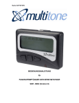
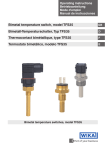
3. Elektrischer Anschluss
Das Heizgerät ist für den Festanschluss an eine Wandanschlussdose vorgesehen, und
muss vom Fachmann installiert werden.
Die Regelung muss zwingend über einen geeigneten Raumthermostaten erfolgen. Siehe
Schaltbild unten
Wenn die Netzanschlussleitung dieses Gerätes beschädigt wird, muss diese durch den
Hersteller Thermotec, deren Kundendienst oder eine ähnlich qualifizierte Person ersetzt
werden, um Gefährdungen zu vermeiden.
Heizung darf nur mit
Thermostat betrieben
werden !
9. Garantie
Für dieses Produkt übernehmen wir 30 Jahre Funktionsgarantie auf das Grundgerät und 2
Jahre Garantie auf die Regelungstechnik, gemäß unseren Garantiebedingungen.
Wir haften nur, wenn die Funktion des Gerätes beeinträchtigt ist und der Defekt nicht
durch unsachgemäße Behandlung, Gewaltanwendung, normalen Verschleiß,
Reparaturversuche von durch uns nicht autorisierte Stellen, den Transport, Fehlgebrauch,
Nichtbeachtung der Bedienungs- oder Montagehinweise, chemisch und oder
elektrochemische Einwirkungen oder sachfremde Betriebsbedienung verursacht wurde.
10. Entsorgungshinweise
Thermotec Geräte sind recyclebar. Bitte führen Sie Ihr Gerät am Ende der
Nutzungsdauer einer sachgerechten Entsorgung zu (örtliche
Sammelstelle).
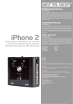
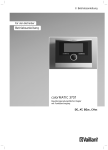
11. Montage
Alle Geräte besitzen vier temperaturbeständige Kunststoffhalter, diese dienen zur besser
Fixierung der Abdeckung auf den Geräten.
Die Thermotec-Heizung sollte unter dem Fenster oder an einer Außenwand des Raumes
montiert werden ( nicht zwingend notwendig). Dabei ist zu beachten, das ein
Mindestabstand von 8 cm zu Boden,10 cm zur seitlichen Wand und 10 cm zum Sims
eingehalten wird. Außerdem darf das Gerät nicht unmittelbar unter einer Wandsteckdose
montiert werden. siehe Abb. 1
1. U-Schienen nach unten stehender Zeichnung montieren Abb. 2
weitere Montage siehe Abb. 3
2. Untere Aufhängungshaken mit Markierung 2 in U-Schienen einhängen
(bitte die Teile mit Markierung 2 für unten benutzen!)
3. Heizung einhängen und schräg nach vorne klappen
4. Obere Aufhängungshaken mit Markierung1 einsetzen und hochziehen
5. Heizung senkrecht stellen
6. Obere Haken nach unten drücken
10cm
Lamelle
Lamelle
X
Einhängeteil
Einhängeteil
8cm
Abb. 2
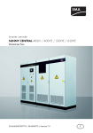
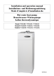
Maß X
90mm
Maß Y
Anbaumaße
190mm
Typ
Maß Y
MINI 650 (TFLH-1)
232 mm
405 mm
COMPACT 1000 / 1300
TFLH 2-3
466 mm
405 mm
MIDI 1500 / 1950
TFLH 4-5
766 mm
405 mm
MAXI 2000 / 2450
TFLH 6-7
1066 mm
405 mm
SLIM 1200
TFLH 12
766 mm
120 mm
SLIM 2000
TFLH 14
1366 mm
120 mm
6. Störungen
Wenn das Heizgerät keine Wärme abgibt, prüfen Sie bitte, ob das Stellrad des
Thermostaten auf die gewünschte Temperatur eingestellt ist; anschließend, ob der
Automat in der Stromverteilung eingeschaltet bzw. die Sicherung in Ordnung ist. Bei
Störungen wenden Sie sich bitte an Ihre Elektrofachwerkstatt oder an die nächstgelegene
Kundendienststelle für Thermotec-Geräte. Für die Auftragsbearbeitung wird die
Seriennummer des Gerätes benötigt. Diese Angabe finden Sie auf dem Typenschild.
SLIM 1600 Tall
TFLH-10
232mm
232mm
Abb. 3
2
1
1
7. Kundendienst
Im Kundendienstfall ist nur die Firma Thermotec oder deren Vertragspartner berechtigt, die
Geräte zu öffnen.
1
1
2
2
2
2
1
1
2
2
2
1040mm
5.Überhitzungsschutz
Zu Ihrer Sicherheit ist das Heizgerät mit einem in der Heizung integrierten
Temperaturschalter ausgerüstet. Bei unzulässiger Erwärmung der Heizung (z.B. durch
Verhängen oder Zustellen des Heizgerätes), schaltet das Gerät automatisch ab. Wie in
Punkt 1 Sicherheitshinweise beschrieben ist das Verhängen z.B. durch Handtücher im
laufenden Betrieb nicht zulässig. Eventuelle Defekte an den Temperaturschaltern und die
daraus resultierenden Kosten für die Reparatur trägt der Verursacher.
Maß X
90mm
935mm
4.Heizbetrieb
Das Heizgerät wird über den extern oder intern angebrachten Raumthermostaten geregelt.
Eine höhere Einstellung am Stellrad bedeutet eine längere Einschaltdauer am Heizgerät.
Bitte beachten Sie hierzu die Bedienungsanleitung der Raumthermostate.
Es ist möglich, das bei Erstinbetriebnahme eine leichte Geruchsentwicklung entstehen
kann, da einige Werkstoffe noch ausgeheizt werden müssen. Dies stellt keine Gefährdung
dar und verschwindet nach einiger Zeit restlos. Bitte lüften Sie die Räume gegebenenfalls
gut durch. In seltenen Fällen kann es zur Geräuschbildung in Form von knacken kommen,
dies wird durch wärme bedingte Materialbewegungen verursacht.
1
UNTEN
Abb. 1
L1
PE
N
8. Reinigen der Geräte
Das Gerät muss vor dem Reinigen ausgeschaltet und abgekühlt sein. Dazu Schalter am
Thermostaten auf Position „Aus" oder Stellrad auf minimale Temperatur stellen. Der
erwärmte Heizkörper darf keinesfalls mit kaltem Wasser „abgeschreckt" werden.
Die Außenseite kann durch Abwischen mit einem weichen, feuchten Lappen gereinigt und
dann getrocknet werden. Zur Reinigung ist Wasser völlig ausreichend. Keine
Scheuerpulver oder sonstige chemische Mittel verwenden, da diese die Oberfläche
beschädigen können.
1
2
Raumthermostat
Wandanschlussdose/
Schukosteckdose
OBEN
Weitere Bilder finden Sie auf Seite 13!
105mm
Bedienungsanleitung
AeroFlow Heizung
Anleitung Displayregler (ITRD)
Grundeinstellung
Konfiguration
19,0
In der Betriebsart AUS öffnen Sie das
erste Konfigurationsmenü, indem Sie
den Ein-Ausschalter 10 Sekunden
lang drücken.
c
Wochentag
Minuten
Uhrzeit einstellen
Wenn sich das Gerät in der Betriebsart
AUS befindet ist folgendes Symbole
im Display
sichtbar.
>10sec.
00:00
Die Tagesanzeige blinkt.
Wählen Sie den gewünschten Tag mit der Taste +
oder – aus. Mit OK bestätigen, dann die Stunde und
danach die Minuten einstellen. Zum Verlassen des
Einstellmodus die Taste Ein-Aus drücken.
Taste
Ein-Aus
F
OK
Nr. des Menüs
Menü 1: Einstellwert Nachtabsenkung regeln.
Standardwert Nachtab. = Wert Komfort minus 3,5°C.
Diese Absenkung lässt sich in Stufen
von 0,5°C von 0 bis 10°C ändern.
3,5
1
2
3
4
5
6
7
Programmieren
----
19,0
Zum Ändern der Programmierung drücken Sie in
Betriebsart AUS oder AUTO
die Taste PROG. Das 1. Zeitfenster blinkt.
1
2
3
4
5
6
7
F
Menü 2: Korrektur der gemessenen Temperatur.
Einstelldisplay
PROG
zwei Striche
“Komfort”
0,0
1
2
3
4
5
6
7
c
ein Strich
“Nachtabsenkung”
00:00
0h
2
4
6
8
10 12 14
1
2
3
4
5
6
7
Ändern mit der Taste + oder –. Danach mit der Taste OK
bestätigen und zur nächsten Einstellung weitergehen.
90
1
2
3
4
5
6
7
0 = Ständige Anzeige der Raumtemperatur.
1 = Ständige Anzeige der eingestellten
Temperatur.
0
1
2
3
4
5
6
7
1 Std. “Frostschutz”
Bedienung
Die verschiedenen Betriebsarten werden mit der
Taste “Betriebsart“ ausgewählt.
Nacht,
Ein-Aus
Betriebsart
Frostschutz, AUTO mit Programmierung.
Die Taste “Betriebsart” wird erst aktiv, wenn das Gerät über die Taste “Ein-Aus”
eingeschaltet wurde. siehe Abb.1
Entsprechend Ihrer Eingabe im Konfigurationsmenü 4 können Sie durch Drücken der
Taste i die Raumtemperatur oder die eingestellte Temperatur anzeigen. Das Symbol
ON in der Anzeige weist darauf hin, dass Heizbedarf besteht.
Komfort Dauerbetrieb
Die Temperatur lässt sich an der Taste + oder
– in Stufen von 0,5°C (von +5 bis +30°C) einstellen.
Abb.1
19,0
c
i
OK
Ändern mit der Taste + oder –. Danach mit der Taste OK
bestätigen und zur nächsten Einstellung weitergehen.
Nachtabsenkung Dauerbetrieb
Der Nachtabsenkung Einstellwert hängt vom Komfort
Einstellwert ab. Die gewünschte Absenkung lässt sich im
Konfigurationsmenü 1 regeln.
Menü 5: Produktnummer.
Mit diesem Menü lässt sich die Produktnummer anzeigen.
Zum Verlassen des Konfigurationsmodus drücken Sie die
OK-Taste.
Bestätigung und
weiter zum nächsten
Tag
1 Std. “Komfort”
Komfort,
OK
Menü 4: Wahl der Temperaturanzeige in der Betriebsart
AUTO.
kein Strich “Frostschutz”
16 18 20 22 24
1 Std. “Nachtabsenkung”
Die Beleuchtungsdauer kann in Stufen von 15 Sekunden
zwischen 0 und 225 Sekunden eingestellt werden.
(Der Standardwert ist 90 Sekunden)
Taste
Tag
OK
OK
Menü 3: Dauer der Hintergrundbeleuchtung.
c
Ein-Aus
F
Ändern mit der Taste + oder –. Danach
mit der Taste OK bestätigen
und zur nächsten Einstellung weitergehen.
Taste
PROG
OK
Wenn die festgestellte Temperatur (Thermometer) von der
vom Gerät gemessenen und angezeigten Temperatur abweicht,
lässt sich im Menü 2 für den Messfühler ein
Kompensationswert zum Ausgleich der Differenz eingeben
(in Stufen von 0,1°C von -5°C bis +5°C).
F
Betriebsart AUS
Bei erster Inbetriebnahme wird für jeden
Tag das Programm "Komfort von 08.00 - 22.00 Uhr"
verwendet.
OK
Ändern mit der Taste + oder –. Danach
mit der Taste OK bestätigen
und zur nächsten Einstellung weitergehen.
Um die Änderung des Einstellwerts
durch den Benutzer zu autorisieren,
drücken Sie die Taste + solange, bis
in der Anzeige "----" erscheint.
Ein-Aus
c
1
2
3
4
5
6
7
Stunde
In Betriebsart AUS
Taste
drücken
PROG
42
1
2
3
4
5
6
7
15,5
c
i
Einstellwert Nachtabsenkung ändern
Der Einstellwert kann nach Autorisierung im
Konfigurationsmenü 1 ("----") geändert werden.
OK
Die Temperatur lässt sich an der Taste + oder
– in Stufen von 0,5°C (von +5 bis +30°C)
einstellen.
15,5
c
i
2
Anleitung Displayregler (ITRD)
Abwesenheitsfunktion
Frostschutz permanent
7,0
Die Temperatur lässt sich an der Taste + oder – in
Stufen von 0,5°C (von +5 bis +15°C) einstellen.
Durch Drücken der Taste
können Sie Ihr Gerät für
die Dauer von 1 bis 365 Tage auf Frostschutz einstellen.
c
PROG
i
F
i
3
OK
Ein-Aus
Betriebsart
Automatikbetrieb
AUTO
In dieser Betriebsart ist das Gerät
programmgesteuert. Zum Änderung der
Programmierung drücken Sie die Taste PROG.
19,0
0h
2
4
6
8
10 12 14
c
i
F
PROG
F
i
F
i
F
Die Tastatur lässt sich sperren, indem die zwei Tasten
mittig 5 Sekunden lang gleichzeitig gedrückt werden. In der
Anzeige erscheint kurz ein "Schlüssel".
Zum Entriegeln drücken Sie erneut gleichzeitig die Tasten
+ und –.
01:30
OK
Stellen Sie die gewünschte Temperatur (+5°C bis +30°C) an der Taste + oder – ein.
Danach mit OK bestätigen und die Zeitdauer einstellen.
Stellen Sie die gewünschte Zeitdauer (von 30 Minuten bis 72 Stunden) an der Taste
+ oder – ein (z.B. 1h30) und bestätigen Sie mit OK. Zum Löschen der befristeten
Temperatureinstellung drücken Sie die Taste OK erneut.
3
Kindersicherung
0---
--
Betriebsart
Zeitbefristete Temperatureinstellung
Durch Drücken der Taste kann ein Temperaturwert
für eine bestimmte Zeitdauer eingestellt werden.
Zum Löschen des Abwesenheitsbetriebs drücken Sie die Taste OK erneut.
PROG
16 18 20 22 24
PROG
Ein-Aus
1
2
3
4
5
6
7
Die Anzahl der Tage Ihrer Abwesenheit stellen
Sie an der Taste + oder – ein und bestätigen mit OK.
Anleitung Drehregler (ITRP)
15°C
20°C
10°C
5°C
25°C
30°C
AUS / OFF
Betriebsanzeigen Beispiele
Gerät ist “AUS”
Gerät ist “AN”
Raumtemperatur
über 5°C
kein Heizbetrieb
Gerät ist “AN”
Raumtemperatur
unter 22°C
Heizbetrieb SSS
Anleitung Funkempfänger
Einlernen des Empfängers
Einlernen eines Raumthermostaten Drücken Sie am Empfänger länger als 3 Sekunden die Taste bis die
Kontrollleuchte zu blinken beginnt. Anschliessend bringen Sie den Sender in Konfigurationsmodus (siehe
Bedienungsanleitung Sender). Wenn die Kontrollleuchte am Empfänger nicht mehr blinkt, sind die beiden Produkte
zugeordnet.
Antenne
Kontrollleuchte
Einlernen eines Domotiksender
Drücken Sie am Empfänger länger als 3 Sekunden die Taste bis die Kontrollleuchte zu blinken beginnt 2 Betriebsarten
sind möglich; Langsames Blinken: Ein/Aus Schalter - Schnelles Blinken: Impulsgeber.
Zum Umschalten der Modi, Taste kurz drücken. Bringen Sie den Sender in den Konfigurationsmodus (Siehe
Bedienungsanleitung Sender). Überprüfen Sie, dass die Kontrollleuchte am Empfänger nicht mehr blinkt.
Taste
Anwendungsbeispiel:
Bei Verwendung eines Raumthermostaten und eines Öffnungsmelders wird durch den Öffnungsmelder der Thermostat
auf Frostschutz geschaltet solange das Fenster geöffnet ist. Die Funktionsweise des Relais kann umgeschaltet werden
(Öffner/Schliesser). Drücken Sie hierzu die Taste des Empfängers ca. 10 s bis das Relais schaltet und die
Kontrollleuchte nicht mehr blinkt.
Zuordnungen Löschen
Zum Löschen aller zugeordneten Produkte Drücken Sie die Taste des Empfängers ca. 30 sek. bis die Kontrollleuchte
kurz aufblinkt. Alle Sender sind nun gelöscht.
Genaue Informationen für den Funksender, entnehmen Sie bitte der beiliegenden Beschreibung im Sender
selbst.
Abdeckung entfernbar
4
Installation & Instructions for use
AeroFlow Heater
1.General
Keep these documents in a safe place. Should the property be sold please pass them on
to the next owner. The appliance is only suitable for heating the room for which it was
specified.
Changing the mains wire or altering the appliances in any way invalidates the guarantee.
A damaged appliance (for example broken mains wire) should not be used until a safety
check has been conducted by a competent electrician.
In case of defect, or suspected defect, the appliance should be isolated from the mains
electricity supply and be inspected by a competent electrician.
Do not cover the heater, so doing could become a Fire risk.
Caution! Outer Panel becomes hot when in use, do not place any articles against the
panels.
Do not use the appliance without consideration of nearby children. (Use guards where
appropriate) Children should be monitored, to ensure that they do not play or tamper with
the appliance.
The appliance needs to be installed so that the temperature controller, switch and wires
cannot be reached from a shower or bath. The latest regulations VDE 0100 part 701 must
be used
the heater is, when mounted correctly, IPX3 proofed (excluding models with integrated
thermostat)
Materials which are flammable such as glue or floor covering should only be used in the
vicinity of the heater after the heater cools down to room temperature.
The heater should not be installed directly under a wall socket.
This appliance should not be operated by persons, (including children) with limited
physical, sensory, limited mental abilities or insufficient experience and/or insufficient
knowledge, unless they are supervised or instructed by a person that is responsible for
their safety.
2. Installation, Minimum distances
The heaters must be installed horizontally on the wall. Fitting in any other way or position
will invalidate the guarantee.
The appliances should be installed so that flammable items cannot catch fire. Caution
must be exercised when installing onto a wooden wall or wood clad surface, particularly
where damp is present. The heat from the appliance may cause wood to warp.
The minimum distances from particularly highly flammable items such as curtains,
upholstered furniture polished tables etc. must be strictly adhered to.
Please make sure that the appliance can radiate heat into the room. (Not be obstructed by
furniture, drawn curtains etc.
Always install wall sockets below or to the side (with safety clearance) of the heater to
prevent the socket and cables overheating.
You must use suitable screws and plugs for the wall type. (The enclosed fixings are for
fixing to solid masonry walls, seek advise for other wall types.)
For positioning of the drill holes for the wall brackets, see installation drawing.
Only the enclosed wall brackets should be used.
3. Electrical Connection
The heater is supplied for use with a 13 amp socket. Where the installation includes fitting
to a fused spur, this work must be carried out by a suitably qualified electrician.
To regulate the room temperature the heater is fitted with either an integral thermostat or
radio frequency controls. Heaters supplied without these controls must be connected to a
suitable room thermostat as shown in the sketch below. Do not site thermostats where
another source of heat can influence the performance. i.e. in direct sunlight, near other
heating appliances, near the rear of a television set etc.
Damage to the main heater cable must be changed by the manufacturer, his service
agent or other qualified persons to avoid danger.
There is a 30 year manufacturers function and parts guarantee for the basic unit, and 2
year for the thermostat.
for 2 years in accordance with warranty details. We are not responsible under guarantee
when the function of the appliance is affected due to any damage as a result of
inappropriate handling, use of force, normal abrasion, repair attempts by unauthorized
persons, transport, misuse, disregard of usage and installation instructions, chemical
and/or electrochemical influence or improper operation.
10. Disposal instructions
Thermotec products are recyclable. Please list your product at the end of
useful life to disposal (local sites).
The heater should be installed under a window or on an outer wall (not mandatory).
Attention should be paid to the minimum distance of 8cm to the floor or floor-covering
surface, 10cm from walls to the side of the heater and 10cm from a window-board or
shelf. DO NOT install the heater directly under a wall socket.
The heater should have clear and open access to the room, not positioned behind
furniture or where it will be covered by full length curtains.
1. Fix the support posts to the wall, using the fixings provided. The open part of the
wall brackets facing the wall.
2. Hook the larger of the two flat metal support hooks into the slots at the bottom of the
wall brackets with the square section facing upwards.
3. Lift the heater onto the bottom brackets with the brackets between the heater ribs,
equal distance from either end of the heater and hold the heater leaning slightly
away from the wall.
4. Hook the other metal support hooks into the wall brackets into the slot at the top of
the wall bracket with the square section pointing downwards.
5. Lean the heater towards the wall
6. Clip the two top brackets onto the top of the heater between the ribs of the heater.
Replace the heater cover
More pics on page 13!
Upwards
Flute
Flute
1
2
Hook
Hook
Abb.1
10cm
Abb. 2
Dimensions
X
90mm
Y
Roomthermostat
Socket
L1
PE
N
190mm
8cm
Typ
6. Failure
Should the heater fail to heat up, please check that the switch of the thermostat is
adjusted to the required temperature. (NOT in the off position)
Check that the heater is connected to the electricity supply.
Check that the socket is working and switched on.
Check that there is a fuse in the plug and that the fuse is working.
If, after these checks the heater fails to heat up, please report to your technical workshop
or to the nearest Service station for Electrorad appliances.
To handle your request we will need the serial number of the heater, which you will find on
the type plate.
Maß X
Maß Y
MINI 650 (TFLH-1)
232 mm
405 mm
COMPACT 1000 / 1300
TFLH 2-3
466 mm
405 mm
MIDI 1500 / 1950
TFLH 4-5
766 mm
405 mm
MAXI 2000 / 2450
TFLH 6-7
1066 mm
405 mm
SLIM 1200
TFLH 12
766 mm
120 mm
SLIM 2000
TFLH 14
1366 mm
120 mm
SLIM 1600 Tall
TFLH-10
232mm
232mm
Abb. 3
2
1
1
7. Service
In case of service, only Electrorad or their contractual partners are permitted to open the
heater.
1
1
2
2
2
2
1
1
2
2
2
1040mm
5. Overheat protection
For your safety the heater is supplied with integrated overheat protection.
In the case of incorrect use of the heater (for example due to covering or fluid spillage) the
appliance will turn off automatically. As described in point 1.
The heater should not be covered for any reason. It should never be used for drying
towels or clothing. The user is responsible for all damage caused to the thermal switches
and the cost of replacement.
8. Cleaning of the heater
The heater must be turned off and completely cooled down. Turn the switch on the
thermostat to the "OFF"-position or the wheel to the minimum temperature. The hot
surface must not be cooled down with water.
The outside can be cleaned and dried by a smooth, damp cloth. Do not use any abrasive
powder or other chemicals, these could damage the surface.
90mm
935mm
4. Using the heater
The heater must be controlled by a room thermostat, either supplied with the heater or one
fitted by a qualified electrician.
The higher the setting of the thermostat will result in longer heating times, higher room
temperature and higher running costs. Please take notice of the instructions of the
thermostat.
During the initial operation of the heater it is possible that the final drying of the internal
clay slabs may cause a smell for a little while. This is normal. Please ensure that the room
is ventilated during this time.
5
Down
X
105mm
Use heater only
with thermostat !
9. Warranty
Instruction digital thermostat (ITRD)
Digital control display
QUICK ACCESS see page 7!
19,0
Configuration
When in Off mode, press and hold down the On/Off
button for 10 seconds to access the first configuration
menu.
c
In Off mode, press the
PROG
If the Heater is in mode „Off”, the display shows
>10sec.
Button
On-Off
1
2
3
4
5
6
7
Hours
button.
00:00
The days flash.
F
Day
Minutes
Time Setting
Press the
button once to access the
programming, and press the On/Off button
once to exit the setting mode.
OK
Menu 1:ECO set-point adjustment
Menu number
By default, Economy setting = Comfort setting - 3.5°C. This
reduction can be set between 0 to -10°C, in steps of 0.5°C.
To adjust the reduction, press on the + or - buttons then press
OK to confirm and go to the next setting.
3,5
1
2
3
4
5
6
7
On-Off
c
Programming
To allow the user to modify the set-point, press on the + button
in Economy mode until “----” is displayed on the screen.
----
19,0
To change the programming, press the PROG button in
Off or AUTO mode. The 1st time slot flashes on and off.
1
2
3
4
5
6
7
F
Control display
Menu 2: Correction of the measured temperature
1
2
3
4
5
6
7
c
PROG
PROG
two strokes
“Comfort”
00:00
one stroke
“Economy”
0h
To modify, press on the + or - buttons then press
OK to confirm and go to the next setting.
OK
To modify, press on the + or - buttons then
press OK to confirm and go to the next setting.
4
6
8
10 12 14
90
1
2
3
4
5
6
7
1
2
3
4
5
6
7
no stroke “Frost protection”
16 18 20 22 24
OK
Comfort
mode for 1 hour
Day
Confirm and go to
the next day
Frost protection
mode for 1 hour
Quick programming:
To apply the same program to the following day, press and hold the OK button for
approximately 3 seconds until the program of the following day is displayed. To exit
the programming mode, press on the On/Off button.
Use
OK
On-Off
Mode button
F
The time out can be adjusted between 0 and 225 seconds,
in steps of 15 seconds (set on 90 seconds by default).
2
Economy mode for 1 hour
Menu 3: Backlight time out setting
Button
On-Off
F
0,0
c
PROG
OK
If there is a difference between the temperature noted
(thermometer) and the temperature measured
and displayed by the unit, menu 2 acts on the measurement
of the probe so as to compensate for this
difference (from -5°C to +5°C in steps of 0.1°C).
Button
Symbol off
When starting up, the “Comfort mode from 8am to
10pm” program is applied to all the days of the week.
OK
F
The “Mode button” allows you to select the different operating modes:
Comfort, Economy,
Frost protection, programming AUTO mode.
Menu 4: AUTO mode temperature display option
0 = Continuous display of room temperature.
1 = Continuous display of set-point
temperature.
0
To modify, press on the + or - buttons then
press OK to confirm and go to the next setting.
1
2
3
4
5
6
7
Pressing the i button gives you the temperature of the room or the set-point
temperature, according to your configuration settings in menu 5.
If the ON icon is displayed, this means that the device is in heating demand mode.
Continuous Comfort
OK
Pressing and holding the + or - buttons lets you change the
current set-point (+5 to +30°C) in steps of 0.5°C.
19,0
c
i
Menu 5: Product number
This menu allows you to view the product number.
To exit the configuration mode, press OK.
42
1
2
3
4
5
6
7
Continuous Economy mode
The Economy set-point is indexed according to the Comfort
set-point. The reduction can be modified in the configuration
settings for menu 1.
15,5
c
i
OK
Modifying the Economy set-point
The set-point can be modified if it was authorized in the
configuration settings in menu 1 (“----”).
Pressing and holding the + or - buttons lets you change the
current set-point (+5 to +30°C) in steps of 0.5°C.
15,5
c
i
6
Instruction digital thermostat (ITRD)
Absence mode
Continuous Frost Protection
Pressing and holding the + or - buttons
lets you change the current set-point
(+5 to +15°C) in steps of 0.5°C.
7,0
You can set your device to Frost protection
mode for a period between 1 and 365 days,
by pressing on the
button.
PROG
Mode button
i
F
i
On-Off
3
c
OK
To set the number of days of absence, press on the + or – buttons, then confirm by
pressing OK.
To cancel this mode, press on the OK button again.
AUTOMATIC mode
AUTO
In this mode the device follows the programming
set. To modify the programming, press the
PROG button once.
19,0
0h
2
4
6
8
10 12 14
c
Locking the keypad
PROG
16 18 20 22 24
PROG
F
i
F
Mode button
i
F
0---
If you press and hold the central buttons simultaneously
during 5 seconds, it enables you to lock the keypad. A key
symbol appears briefly on the display. To unlock the
keypad, press simultaneously on the central buttons.
--
On-Off
1
2
3
4
5
6
7
Timer mode
To set a set-point temperature for a certain
period of time, press on the
button once.
PROG
F
i
Once the keypad is locked, the key symbol appears briefly
if you press on a button.
01:30
OK
To set the temperature you want (+5°C to +30°C), use the + and - buttons, then press OK
to confirm and go on to set the duration.
To set the duration you want (30 min to 72 hours, in steps of 30 min), use the + and –
buttons (e.g. 1 hr 30 min), then press OK. To cancel the timer mode, press on the OK
button.
ADDITIONAL PROGRAMMING INSTRUCTIONS
FOR USE WITH:
The first page of the instructions packed with the radiator show factory pre-set positions, which for general use can be ignored at this stage.
QUICK ACCESS
Time setting.
In OFF mode (PRESS button (5) ON/OFF button to set OFF mode)
PRESS button (6) The days of the week 1-7 will flash at the right hand side of the screen.
00:00 will show on the screen. This represents the 24 hour clock.
Select current day of the week by pressing + or - button, (button (2) = Minus Button (3) = plus) 1-Monday, 2 -Tuesday, 3 -Wednesday etc.
(a small arrow will point to each day of the week.) When CURRENT day of the week is selected PRESS OK button (4).
Time 00:00 will flash. PRESS + or – button to change hour to correct time, when hour is set PRESS OK (4) Minutes will flash. PRESS + or – button to change minutes to
correct time. When time is set PRESS OK (4) PRESS ON/OFF Button (5)
Programme setting.
Press the Program button.(2) The 24 hour clock will show 00:00.
EACH press of button (3) will give 1 hour of FROST PROTECTION.
The 24 hour clock display will move forward 1 hour for each press of the button.
The display at the bottom of the screen will show a line with no blocks displayed.
i.e. 6 presses of the button will give a frost protection from 12 midnight until 6 a.m.
The clock will show 06:00
There is no OFF position for the radiator. For normal use there is no need to turn the radiator OFF.
The FROST PROTECTION setting on the programming is in effect the OFF position.
The clock is now showing 06:00 (6 hours of frost protection)
With the FROST PROTECTION setting the radiator will only switch on if the temperature drops below 7 degrees ‘C’.
19,0
c
PROG
1
2
5
7
3
4
6
Instruction knob thermostat (ITRP)
15°C
20°C
10°C
5°C
25°C
30°C
OFF
Operational use display examples:
Equipment is “off”
Equipment is “on”, Room
temperature higher than 5 ° C,
no heating
Equipment is “on”, Room
temperature under 22 ° C,
heating on SSS
Instruction wireless receiver
Associating the receiver
With a transmitter thermostat Press the receiver button until the LED flashes (~3 seconds). Put the transmitter into
association mode (see transmitter guide). Check that the receiver LED is no longer flashing. The receiver is associated
with the transmitter.
With a control system transmitter
Press the receiver button until the LED flashes (~3 seconds). 2 possible choices. Slow flashing: simple lighting mode
Rapid flashing: pulse mode. Press the receiver button briefly to pass from One rate of flashing to the other.
On the transmitter, send the association radio information (see transmitter guide). Check that the receiver’s LED is no
longer
Flashing.
Antenna
LED
Button
Application example:
with a door/window magnetic contact. When associated with the receiver,
the magnetic contact can: - in control system mode, report the magnetic contact's status (open/closed), - in heating
mode, for instance when there is
an open window, switch the heating to frost protection.
Removing all the receiver associations
Press and hold the button. The LED flashes after 3 seconds.
Hold down the button. The relay reverses after 10 seconds and the LED no longer flashes (reverse current relay mode
active). Hold down the button.
The LED flashes after 30 seconds; all the associations are removed. Release the button.
Removable cover
8
INSTALLATION ET MODE D'EMPLOI
AeroFlow chauffage
1. Sécurité
Veuillez'il vous plaît lire attentivement toutes les informations énumérées dans la présente
notice. Conservez ces instructions avec soin et transmettez-les si besoin aux futurs
propriétaires. Un équipement défectueux (par exemple câbles endommagés) ne doit pas être
exploité.
Si une erreur se produit, débrancher l'appareil du secteur (ou couper le fusible).
Ne pas couvrir le radiateur, attention au feu!
Attention! Les surfaces extérieures sont chaudes pendant le fonctionnement. Ne laissez pas
fonctionner le radiateur sans surveillance lorsque des enfants en bas âge sont à proximité.
L'appareil doit être installé de façon à ce qu'aucune des sondes de température, des
commutateurs et des câbles ne puissent être en contact direct avec une arrivée d'eau telle
que douche ou baignoire. Nos pierres réfractaires ont été testées IPX3 (protection contre les
projections d'eau).
Nos radiateurs ne peuvent être utilisés près matériaux qui sont sujets à l'inflammation ou la
décomposition thermique (plancher de gluten par exemple), sauf s'il est garanti que les
radiateurs ont refroidi et sont à température ambiante.
Le chauffage ne doit pas être placé directement sous une prise murale.
Ce dispositif n'est pas destiné à être utilisé par des personnes (y compris les enfants)
présentant une réduction des capacités physiques, sensorielles ou mentales ou des
personnes présentant un manque d'expérience et / ou des connaissances de l'appareil. Sauf
si elles sont surveillées par une personne responsable de leur sécurité ou ont reçu des
instructions sur la façon d'utiliser l'appareil.
Les enfants doivent être surveillés pour s'assurer qu'ils ne jouent pas avec le radiateur.
2.Installation et distances de sécurité
Nos appareils doivent être montés horizontalement sur le mur. Le montage vertical n'est
pas autorisé et entraînerait l'annulation de la garantie.
Ils doivent être disposés de manière à ce qu'aucun objet inflammable ne puisse entrer en
contact avec ces derniers.
9. Garantie
Ce produit est garanti pour une durée de 30 ans sur l'unité de base (Thermostats deux
années), conformément à nos conditions de garantie. La garantie ne sera valable que si le
fonctionnement initial de l'appareil est altéré. Les pannes dûes à une mauvaise
manipulation, un abus, une usure normale, des tentatives de réparation non autorisées
par Thermotec, le transport, une utilisation abusive, le non-respect des instructions de
fonctionnement ou d'installation, ne seront pas couvertes par la garantie.
10. Destruction
Les produits Thermotec sont recyclables. Si votre radiateur est en fin de
vie, merci de le déposer dans un centre de recyclage.
11. Montage/Assemblage
Tous les radiateurs sont équipés de quatre supports en plastique, hautement résistant à la
chaleur, ils servent à fixer solidement le couvercle à l'appareil.
12. Le radiateur Thermotec doit être installé de préférence sous une fenêtre ou sur un mur
extérieur. Notez qu'une distance minimale de sécurité de 8 cm au sol, et de 10 cm à partir
des côtés et du haut de l'appareil est à respecter. En outre, le dispositif ne doit pas être
monté directement sous une prise murale. Voir Figure 1
12-1. Fixer les rails au mur, la partie ouverte de ces derniers faisant face au mur. (Voir
schéma 2 pour les distances d'écartement entre chaque rail)
Schéma 3
12-2. Insérer les crochets du bas dans les rails de fixation.
12-3. Poser le radiateur sur les crochets du bas en le gardant légèrement incliné vers
l'avant.
12-4. Insérer les crochets du haut dans les rainures tout en les maintenant vers le haut
12-5. Redresser le radiateur
12-6. Pousser les crochets vers le bas ce qui fixera solidement votre radiateur.
Plus de photos sur la page 13!
surtout lorsque les appareils sont fixés près d'une surface en bois ou sur des murs en
placoplâtre.
crochet du haut
Une distance minimale de sécurité, en particulier avec les articles inflammables tels que
rideaux, tissus d'ameublement, etc, doit être respectée. Toujours passer le câble ou la
prise par le dessous ou les côtés du radiateur pour éviter toute surchauffe. Selon la
composition du mur, toujours utiliser des vis et chevilles adaptées. Pour positionner
correctement les trous des fixations murales voir schéma "Aide à l'installation". Seuls les
supports muraux fournis par l'usine sont adaptés.
3. Raccordement électrique
Le radiateur est conçu pour une connexion permanente au secteur ou à une prise murale,
et doit être installé par un professionnel.
Nos radiateurs doivent être pilotés par des thermostats d'ambiance appropriés. Voir le
schéma ci-dessous
Si le cordon d'alimentation est endommagé, il doit être remplacé par le fabricant
Thermotec, veuillez contacter votre revendeur ou une personne qualifiée afin d'éviter tout
danger.
1
X
crochet du bas
2
Figure 1
10cm
Schéma 2
Dimensions
X
Thermostat
90mm
L1
PE
N
4. Utilisation du Chauffage
Ce dispositif de chauffage est prévu pour être commandé par un thermostat intégré ou un
thermostat déporté à ondes radio. Plus la température choisie est élevée, plus la
consommation énergétique sera importante. Reportez vous à la notice du thermostat.
Y
190mm
90mm
8cm
Typ
A la première utilisation, il est possible qu'il se dégage du radiateur une légère odeur de
brûlé (comme tous matériel électrique neuf). Cette odeur est normale et ne présente
aucun danger. Elle disparaîtra très rapidement.
Il se peut également que vous entendiez quelques bruits de craquements à la première
utilisation, ceci est normal et correspond à la dilatation du matériel.
MINI 650 (TFLH-1)
232 mm
405 mm
COMPACT 1000 / 1300
TFLH 2-3
466 mm
405 mm
MIDI 1500 / 1950
TFLH 4-5
766 mm
405 mm
MAXI 2000 / 2450
TFLH 6-7
1066 mm
405 mm
SLIM 1200
TFLH 12
766 mm
120 mm
SLIM 2000
TFLH 14
1366 mm
120 mm
SLIM 1600 Tall
TFLH-10
232mm
232mm
6. Dysfonctionnements
Si le chauffage ne se met pas en route, vérifiez que la température souhaitée soit bien
sélectionnée sur le thermostat. Si l'appareil ne fonctionne toujours pas, vérifiez l'arrivée de
courant et le fusible. En cas de dysfonctionnement, veuillez s'il vous plaît contacter votre
revendeur Thermotec. Pour le traitement du service après vente, le numéro de série est
nécessaire, vous le trouverez sur la plaque signalétique de chaque appareil.
Schéma 3
2
7. Service après vente
En cas de panne, seule la société Thermotec est habilitée à ouvrir l'appareil.
1
1
8. Nettoyage des appareils
L'appareil doit être éteint et refroidi avant de procéder à son nettoyage. Pour ce faire
basculer sur le thermostat sur la position "off" ou tournez la molette sur la position "0". Un
radiateur encore chaud ne doit pas être nettoyé avec de l'eau froide.
L'extérieur peut être simplement nettoyé à l'aide d'un chiffon doux et humide, puis séché.
Pour nettoyer vos appareils l'eau est suffisante. Ne pas utiliser de poudre à récurer ou
d'autres agents chimiques, ils pourraient endommager la surface du radiateur.
1
1
2
2
2
2
1
1
2
9
2
2
1040mm
Maß Y
935mm
5. protection contre la surchauffe
Pour votre sécurité, le chauffage est équipé d'un système de sécurité destiné à éviter toute
surchauffe. Si le radiateur est recouvert ou que les aérations sont bloquées ou
recouvertes, l'appareil s'éteint automatiquement. Il est bien entendu interdit de recouvrir le
radiateur en y posant par exemple une serviette ou tout autre objet.
Maß X
105mm
Ce chauffage ne peut
être utilisé qu'avec un
thermostat!
Lamelle
Lamelle
Instructions thermostat (ITRD)
Digital control display
Configuration
A partir du mode Arrêt,
appuyez pendant 10 secondes sur la
toucheMarche/Arrêt pour entrer dans le premier menu
de configuration.
19,0
c
If the Heater is in mode „Off”, the display shows
>10sec.
F
Houres
A partir du mode Arrêt, appuyez sur
la touche
Les jours clignotent.
PROG
Button
On-Off
Jour
Minutes
Mise à l’heure
00:00
Appuyez sur + ou - pour choisir le jour, puis appuyez
sur OK pour valider et passer au réglage de l’heure
puis des minutes. Un appui sur la touche Marche /
Arrêt permet de sortir du mode de réglage.
1
2
3
4
5
6
7
OK
N° de menu
Menu 1 : Réglage de la consigne ECO.
Par défaut, consigne Economie = consigne Confort - 3,5°C.
Cet abaissement est modifiable de 0 à -10°C, par pas de
0,5°C. Pour modifier, appuyez sur les touches + ou -, puis
appuyez sur la touche OK pour valider et passer au réglage
suivant.
Pour autoriser la modification par l’utilisateur de la consigne,
lors du mode Economie permanent, appuyez sur la touche +
jusqu’à l’affichage “----”.
3,5
1
2
3
4
5
6
7
On-Off
c
----
A la mise en service, le programme “Confort de 8h à
22h” est appliqué à tous les jours de la semaine.
Pour modifier la programmation, à partir du mode Arrêt
ou AUTO, appuyez sur la touche PROG. Le 1er
créneau horaire clignote.
1
2
3
4
5
6
7
19,0
F
0,0
c
1 lignes
“Economie”
00:00
0h
2
4
6
8
10 12 14
1
2
3
4
5
6
7
Jour
pas de lignes
“Hors-gel”
16 18 20 22 24
OK
Validation et
passage au jour suivant
1h de confort
1h d'hors-gelr
1h d'économie
90
1
2
3
4
5
6
7
Programmation rapide :
Pour appliquer le même programme au jour suivant, maintenez appuyée la touche
OK environ 3 secondes jusqu’à afficher le programme du jour suivant. Pour sortir du
mode programmation, appuyez sur la touche Marche/Arrêt
Utilisation
OK
On-Off
Mode button
F
Pour modifier, appuyez sur les touches + ou - puis appuyez
sur la touche OK pour valider et passer au réglage suivant.
PROG
PROG
2 lignes
“Confort”
OK
Menu 3 : Temporisation du rétro-éclairage.
Temporisation réglable de 0 à 225 secondes par pas de 15
secondes, (90 secondes par défaut).
Control display
1
2
3
4
5
6
7
Pour modifier, appuyez sur les touches + ou puis appuyez sur la touche OK pour valider et
Passer au réglage suivant.
Button
On-Off
F
S’il existe un écart entre la température constatée
(thermomètre) et la température mesurée et affichée par
l’appareil, le menu 2 permet d’agir sur la mesure de la
sonde de façon à compenser cet écart (-5°C à +5°C, par
pas de 0,1°C).
c
PROG
OK
Menu 2 : Correction de la température mesurée.
Button
icône en congé
Programmation
OK
F
La touche Mode permet de sélectionner les différents mode de
fonctionnement :
Confort, Economie, Hors-gel, AUTO avec programmation.
Menu 4 : Choix de l’affichage de la température en
mode AUTO.
0 = Affichage permanent de la température Ambiante.
1 = Affichage permanent de la température de consigne.
0
Pour modifier, appuyez sur les touches + ou - puis appuyez
sur la touche OK pour valider et passer au réglage suivant.
1
2
3
4
5
6
7
Un appui sur la touche i permet de connaître la température ambiante ou la
température de consigne, selon votre choix lors de la configuration du menu 4.
L’affichage du picto ON indique que l’appareil est en demande de chauffe.
Confort permanent
OK
Un appui sur les touches + ou - permet de modifier la
consigne (de +5 à +30°C) en cours par pas de 0,5°C.
19,0
c
i
Menu 5 : Numéro du produit.
Ce menu vous permet de consultez le numéro du produit.
Appuyez sur la touche OK pour sortir du mode
configuration.
42
1
2
3
4
5
6
7
Economie permanent
La consigne Economie est indexée par rapport à la
consigne Confort. L’abaissement est modifiable lors de la
configuration du menu 1.
15,5
c
i
OK
Modification de la consigne Economie
La modification de la consigne est possible, si elle a été
autorisée lors de la configuration du menu 1 (“----”).
Un appui sur les touches + ou - permet de modifier la
consigne (de +5 à +30°C) en cours par pas de 0,5°C.
15,5
c
i
10
Instructions thermostat (ITRD)
Mode Absence
Utilisation
Hors gel permanent Un appui sur les touches + ou permet de modifier la consigne (de +5 à +15°C) en
cours par pas de 0,5°C.
7,0
Un appui sur la touche
permet de mettre
votre appareil en Hors-gel pour une
durée de 1 à 365 jours.
c
PROG
On-Off
Mode button
i
F
i
3
OK
Appuyez sur + ou - pour régler le nombre de jours d’absence, puis appuyez sur OK
pour valider.
Pour annuler ce mode absence appuyez de nouveau sur la touche OK.
Mode AUTOMATIQUE
AUTO
Dans ce mode l’appareil suit la programmation. Un
appui sur la touche PROG permet de modifier la
programmation.
19,0
0h
2
4
6
8
10 12 14
c
i
F
i
F
Un appui simultané sur les touches + et - pendant 5
secondes, permet de verrouiller le clavier. La clé s’affiche
brièvement.
Pour déverrouiller, appuyez de nouveau simultanément
sur les touches + et -.
Un appui sur la touche permet de régler
une température de consigne pour une durée
donnée.
PROG
i
01:30
OK
Appuyez sur + ou - pour régler la température souhaitée (+5°C à +30°C) puis appuyez
sur OK pour valider et passer au réglage de la durée. Appuyez sur + ou - pour régler la
durée souhaitée (de 30 min à 72 h) par pas de 30 minutes (ex : 1h30), validez sur OK.
Pour annuler ce mode sablier appuyez de nouveau sur la touche OK.
11
F
0---
--
Mode button
Mode Sablier
F
Vérrouillage du clavier
PROG
16 18 20 22 24
PROG
On-Off
1
2
3
4
5
6
7
Instructions thermostat (ITRP)
15°C
20°C
10°C
5°C
25°C
30°C
OFF
Operational use display examples:
Equipment is “off”
Equipment is “on”, Room
temperature higher than 5 ° C,
no heating
Equipment is “on”, Room
temperature under 22 ° C,
heating on SSS
Instructions récepteur radio
Avec un thermostat émetteur
Sur le récepteur, appuyez sur la touche jusqu’à ce que le voyant clignote (~3 secondes).
Mettez l’émetteur en mode association (voir sa notice). vérifiez que la voyant du récepteur ne
clignote plus. Le récepteur est associé à l’émetteur. Avec un émetteur d’automatisme
Avec un émetteur d’automatisme
Sur le récepteur, appuyez sur la touche jusqu’à ce que le voyant clignote (~3 secondes).
2 choix sont possibles. Clignotement lent : mode simple allumage. Clignotement rapide :
mode impulsionnel. Pour passer d’un clignotement à l’autre, appuyez brièvement sur la
touche du récepteur.
Antenne
Voyant
Touche
Sur l’émetteur, envoyez l’information radio d'association (voir sa notice). Vérifiez que le
voyant du récepteur ne clignote plus.
Exemple d’application : avec un détecteur d’ouverture. Associé au récepteur, le détecteur
permet : - en automatisme, de reporter l’état du détecteur (ouvert/fermé), - en chauffage, par
exemple en cas d’ouverture d’une fenêtre, de passer le chauffage en hors-gel.
Effacer toutes les associations au récepteur
Maintenez appuyée la touche. Après 3 secondes, le voyant clignote. Maintenez l’appui. Après
10 secondes, le relais s’inverse et le voyant ne clignote plus (mode relais inverseur actif).
Maintenez l’appui. Après 30 secondes, le voyant clignote (flash), toutes les associations sont
effacées. Relâchez la touche.
Capot amovible
12
13
14
MADE IN GERMANY
warranty certificate
Hersteller
Thermotec AG
Arnsdorf 26
02894 Vierkirchen
THERMOTEC AG
WARRANTY ZERTIFIKAT
Garantie Zertifikat
MADE IN GERMANY