1
D
Montage- und
Bedienungsanleitung
Funk-Wandthermostat
HM-CC-TC
Seite 4 - 30
Installation and
Operating Manual
GB
Radio-controlled
room thermostat
HM-CC-TC
Page 32 - 58
1. Ausgabe Deutsch 10/2008
Dokumentation © 2007 eQ-3 Ltd., Hong Kong
Alle Rechte vorbehalten. Ohne schriftliche Zustimmung des
Herausgebers darf dieses Handbuch auch nicht auszugsweise
in irgendeiner Form reproduziert werden oder unter Verwendung
elektronischer, mechanischer oder chemischer Verfahren vervielfältigt oder verarbeitet werden.
Es ist möglich, dass das vorliegende Handbuch noch drucktechnische Mängel oder Druckfehler aufweist. Die Angaben in diesem
Handbuch werden jedoch regelmäßig überprüft und Korrekturen
in der nächsten Ausgabe vorgenommen. Für Fehler technischer
oder drucktechnischer Art und ihre Folgen übernehmen wir keine
Haftung.
Alle Warenzeichen und Schutzrechte werden anerkannt.
Printed in Hong Kong
Änderungen im Sinne des technischen Fortschritts können ohne
Vorankündigung vorgenommen werden.
76190 / V 1.02
2
1. English edition 10/2008
Documentation © 2007 eQ-3 Ltd., Hong Kong
All rights reserved. No parts of this manual may be reproduced or
processed in any form using electronic, mechanical or chemical
processes in part or in full without the prior explicit written permission of the publisher.
It is quite possible that this manual has printing errors or defects.
The details provided in this manual are checked regularly and
corrections are done in the next edition. We do not assume any
liability for technical or printing errors.
All registered trade marks and copyrights are acknowledged.
Printed in Hong Kong
We reserve the right to make changes due to technical advancements without prior notice.
76190 / V 1.02
3
Inhaltsverzeichnis
1
Hinweise zu dieser Anleitung . . . . . . . . . . . . . . . . . . . . . . . .6
2
Gefahrenhinweise . . . . . . . . . . . . . . . . . . . . . . . . . . . . . . . . .6
3
Funktion. . . . . . . . . . . . . . . . . . . . . . . . . . . . . . . . . . . . . . . . .6
4
Allgemeine Systeminformation zu HomeMatic . . . . . . . . . .8
5
Allgemeine Hinweise zum Funkbetrieb . . . . . . . . . . . . . . . .8
6
Inbetriebnahme . . . . . . . . . . . . . . . . . . . . . . . . . . . . . . . . . . .9
6.1
Batterien einlegen und wechseln . . . . . . . . . . . . . . . . . . . . .9
6.1.1 Batterien einlegen . . . . . . . . . . . . . . . . . . . . . . . . . . . . . . . . .9
6.1.2 Verhalten nach Einlegen der Batterie . . . . . . . . . . . . . . . . .10
6.1.3 Batterien wechseln . . . . . . . . . . . . . . . . . . . . . . . . . . . . . . .11
6.2
Montage. . . . . . . . . . . . . . . . . . . . . . . . . . . . . . . . . . . . . . . .12
6.2.1 Lieferumfang . . . . . . . . . . . . . . . . . . . . . . . . . . . . . . . . . . . .12
6.2.2 Montage des Wandhalters . . . . . . . . . . . . . . . . . . . . . . . . .12
7
Bedienung . . . . . . . . . . . . . . . . . . . . . . . . . . . . . . . . . . . . . .13
7.1
Übersicht . . . . . . . . . . . . . . . . . . . . . . . . . . . . . . . . . . . . . . .13
7.2
Betriebsarten. . . . . . . . . . . . . . . . . . . . . . . . . . . . . . . . . . . .14
7.2.1 Automatik-Betrieb . . . . . . . . . . . . . . . . . . . . . . . . . . . . . . . .14
7.2.2 Handbetrieb. . . . . . . . . . . . . . . . . . . . . . . . . . . . . . . . . . . . .14
7.2.3 Urlaubs-/Partyfunktion . . . . . . . . . . . . . . . . . . . . . . . . . . . .14
7.2.4 Zentralengeführter Betrieb . . . . . . . . . . . . . . . . . . . . . . . . .15
7.3
Einstellungen im Auslieferungszustand . . . . . . . . . . . . . . .16
7.4
Einstellen von Komfort- und Absenktemperatur . . . . . . . .16
7.5
Heizpause . . . . . . . . . . . . . . . . . . . . . . . . . . . . . . . . . . . . . .17
7.6
Frostschutzbetrieb . . . . . . . . . . . . . . . . . . . . . . . . . . . . . . .18
4
7.7
Tastensperre . . . . . . . . . . . . . . . . . . . . . . . . . . . . . . . . . . . .18
7.8
Absenkbetrieb bei geöffneten Fenstern. . . . . . . . . . . . . . .18
8
Konfiguration und Sonderfunktionen . . . . . . . . . . . . . . . . .20
8.1
Einstellungen für den Automatikbetrieb „PRG“. . . . . . . . .21
8.2
Einstellen von Datum und Uhrzeit „DAT“ . . . . . . . . . . . . . .23
8.3
Statusabfrage Stellantrieb „VST“ . . . . . . . . . . . . . . . . . . . .23
8.4
Statusabfrage Tür-/Fenstersensoren „WST“ . . . . . . . . . . .23
8.5
Anlernen und Ablernen von Geräten „KON“ . . . . . . . . . . .24
8.6
Einstellungen zur automatischen Entkalkungsfahrt „DEC“ 25
8.7
Einstellen der verwendeten Temperatureinheit „C/F“ . . . .25
8.8
Einstellung der Anzeige Soll-/Istwert „A/S“ . . . . . . . . . . . .26
8.9
Einstellung der Anzeige von Temperatur/Luftfeuchte „T/H“26
8.10 Einstellung der Displayhinterleuchtung „ LIG“ . . . . . . . . .26
8.11 Einstellung der Offsetwerte für die einzelnen Stellantriebe
„OFF“ . . . . . . . . . . . . . . . . . . . . . . . . . . . . . . . . . . . . . . . . . .27
8.12 Einstellen der Solltemperatur beim Lüften
(Fenster-Auf-Temperatur) „WOT“ . . . . . . . . . . . . . . . . . . . .27
8.13 Einstellen der Position bei Störungen am Stellantrieb
„EPO“. . . . . . . . . . . . . . . . . . . . . . . . . . . . . . . . . . . . . . . . . .28
8.14 Zurücksetzen in den Auslieferungszustand „RES“ . . . . . .28
9
Fehlermeldungen . . . . . . . . . . . . . . . . . . . . . . . . . . . . . . . .29
10
Wartung und Reinigung . . . . . . . . . . . . . . . . . . . . . . . . . . .29
11
Technische Daten . . . . . . . . . . . . . . . . . . . . . . . . . . . . . . . .30
5
1
Hinweise zu dieser Anleitung
Lesen Sie diese Anleitung sorgfältig, bevor Sie ihre HomeMatic
Komponenten in Betrieb nehmen.
Bewahren Sie die Anleitung zum späteren Nachschlagen auf!
Wenn Sie das Gerät anderen Personen zur Nutzung überlassen,
übergeben Sie auch diese Bedienungsanleitung.
Benutzte Symbole:
Achtung! Hier wird auf eine Gefahr hingewiesen.
Hinweis. Dieser Abschnitt enthält zusätzliche wichtige
Informationen!
2
Gefahrenhinweise
Betreiben Sie das Gerät nur in Innenräumen und vermeiden Sie
den Einfluss von Feuchtigkeit, Staub sowie Sonnen- oder andere
Wärmebestrahlung.
Öffnen Sie das Gerät nicht, es enthält keine durch den Anwender
zu wartenden Teile.
3
Funktion
Der Funk-Wandthermostat (HM-CC-TC) ist ein Einzelraumregler.
Er misst die Raumtemperatur und vergleicht die gemessene
Temperatur mit der durch das Zeitprogramm bzw. der von Hand
vorgegebenen Soll-Temperatur. Aus der Differenz errechnet der
Regelalgorithmus, wie der oder die Funk-Stellantriebe (HM-CC-VD)
das Ventil fahren müssen, um die gewünschte Temperatur zu
erreichen.
6
In einem zyklischen Zeitraster, mit einer Zykluszeit zwischen 120
und 184 Sekunden, überträgt der Wandthermostat Befehle zu
dem am Heizkörper montierten Stellantrieb. Der Stellantrieb bestätigt den übertragenen Funk Befehl und steuert die zugeführte
Wärmeträgermenge entsprechend.
Über die HomeMatic Zentrale ist es möglich Veränderungen der
Temperaturvoreinstellung oder des Zeitprogramms im Wandthermostaten bequem über eine grafische Oberfläche vorzunehmen.
Die Regelung wird weiterhin im entsprechenden Raum autark
vom Wandthermostat durchgeführt.
Durch Anlernen eines oder mehrerer Tür-Fensterkontakte bzw.
Fenster-Drehgriffkontakte am Wandthermostat, kann die Fensterstellung (offen/geschlossen) ausgewertet werden und in den
Regelalgorithmus einfließen.
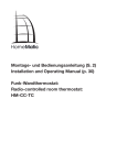
(A)
(B)
(C)
(D)
(E)
(F)
(G)
Stellrad (zur Dateneingabe)
Geräte-LED
Display
Bedientasten (Menu, OK, Tag-/Nachtumschaltung)
Aufnahme Wandhalter
Batteriefach
Wandhalter
7
4
Allgemeine Systeminformation zu
HomeMatic
Dieses Gerät ist Teil des HomeMatic Haussteuersystems und
arbeitet mit dem bidirektionalen BidCoS® Funkprotokoll.
Alle Geräte werden mit einer Standardkonfiguration ausgeliefert.
Darüber hinaus ist die Funktion des Gerätes über ein Programmiergerät und Software konfigurierbar. Welcher weitergehende
Funktionsumfang sich damit ergibt, und welche Zusatzfunktionen sich im HomeMatic System im Zusammenspiel mit weiteren
Komponenten ergeben, entnehmen Sie bitte der gesonderten
Konfigurationsanleitung oder dem HomeMatic Systemhandbuch.
Alle technischen Dokumente und Updates finden Sie stets aktuell
unter www.HomeMatic.com.
5
Allgemeine Hinweise zum Funkbetrieb
Die Funk-Übertragung wird auf einem nicht exklusiven Übertragungsweg realisiert weshalb Störungen nicht ausgeschlossen
werden können.
Weitere Störeinflüsse können hervorgerufen werden durch
Schaltvorgänge, Elektromotoren oder defekte Elektrogeräte.
Die Reichweite in Gebäuden kann stark von der im
Freifeld abweichen. Außer der Sendeleistung und den
Empfangseigenschaften der Empfänger spielen Umwelteinflüsse wie Luftfeuchtigkeit neben baulichen Gegebenheiten
vor Ort eine wichtige Rolle.
Hiermit erklärt die eQ-3 Entwicklung GmbH, dass sich dieses
Gerät in Übereinstimmung mit den grundlegenden Anforderungen und den anderen relevanten Vorschriften der Richtlinie
1999/5/EG befindet.
Die vollständige Konformitätserklärung finden Sie unter:
www.HomeMatic.com.
8
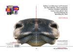
Zur Wandmontage des Wandthermostaten zeichnen Sie die
Bohrlöcher anhand des Wandhalters an. Dabei muss der Wandhalter mit der halbkreisförmigen Seite nach oben und mit der
Seite mit der kleinen halbkugelförmigen Vertiefung im oberen Teil
nach vorne orientiert sein. Zum Anzeichnen markieren Sie eine
Position in der Mitte der Langlöcher für die Schrauben.
Bohren Sie mit einem 6 mm Bohrer Befestigungslöcher, und
benutzen Sie die mitgelieferten Dübel und Schrauben zur Befestigung. Bevor Sie die Schrauben des Wandhalters endgültig
festdrehen, können Sie den Halter mit Hilfe einer Wasserwaage
endgültig ausrichten und dann die Schrauben fest ziehen.
6
Inbetriebnahme
6.1
Batterien einlegen und wechseln
6.1.1 Batterien einlegen
Zum Einlegen oder Wechseln der Batterie legen Sie den Wandthermostat mit dem Display nach unten auf eine weiche Unterlage (damit die Blende und die Displayabdeckung nicht verkratzen). Schieben Sie den Batteriefachdeckel in Pfeilrichtung und
nehmen ihn ab. Legen Sie zwei Mignon Batterien polungsrichtig
ins Batteriefach (siehe Zeichnung).
9
6.1.2 Verhalten nach Einlegen der Batterie
Nach dem Einlegen der Batterien erfolgt ein kurzer Test der
LC-Anzeige mit anschließender Anzeige der Versionsnummer.
Sie müssen nun nacheinander Datum und Uhrzeit eingeben.
Dazu verwenden Sie das Stellrad. Bestätigen Sie danach ihre
Eingabe mit der „OK“-Taste und Sie gelangen zum nächsten
Eingabeschritt. Während der Datums- und Zeiteingabe können
Sie mit der „Menu“-Taste jederzeit wieder zum vorhergehenden
Schritt wechseln.
s¬ +ALENDERJAHR
s¬ +ALENDERMONAT
s¬ 7OCHENTAG
10
s¬ :EITEINSTELLUNG¬ ¬3TUNDEN
s¬ :EITEINSTELLUNG¬ ¬-INUTEN
Damit sind Datum und Uhrzeit im Heizungsregler eingestellt und
es wird zur Standardanzeige gewechselt.
Wird der Heizungsregler an eine Zentrale angelernt, wird der
Regler beim nächsten Batteriewechsel Datum und Uhrzeit von
der Zentrale anfordern, gelingt dies, wird sofort zu Standardanzeige gewechselt.
6.1.3
Batterien wechseln
Vorsicht! Explosionsgefahr bei unsachgemäßem Austausch der
Batterie.
Verbrauchte Batterien gehören nicht in den
Hausmüll! Entsorgen Sie diese in Ihrer örtlichen
Batteriesammelstelle!
Werden fast leere Batterien für den Wandthermostaten gemeldet
(siehe Abschnitt 9 Fehlermeldungen) müssen Sie die alten Batterien
durch zwei neue des Typs LR6 (Mignon) ersetzen. Öffnen Sie wie
oben beschrieben das Batteriefach, entnehmen Sie die alten Batterien und legen Sie neue ein. Achten Sie dabei auf die richtige Polung.
11
6.2
Montage
6.2.1
Lieferumfang
s¬ 7ANDTHERMOSTAT
s¬ 7ANDHALTER
s¬ ¬3TàCK¬(OLZSCHRAUBEN¬ ¬X¬
s¬ ¬3TàCK¬$àBEL¬¬MM
s¬ ¬3TàCK¬"ATTERIEN¬,2¬-IGNON
6.2.2
Montage des Wandhalters
Zur Wandmontage des Wandthermostaten zeichnen Sie die
Bohrlöcher anhand des Wandhalters an. Dabei muss der Wandhalter mit der halbkreisförmigen Seite nach oben und mit der
Seite mit der kleinen halbkugelförmigen Vertiefung im oberen Teil
nach vorne orientiert sein. Zum Anzeichnen markieren Sie eine
Position in der Mitte der Langlöcher für die Schrauben.
Bohren Sie mit einem 6 mm Bohrer Befestigungslöcher, und
benutzen Sie die mitgelieferten Dübel und Schrauben zur Befestigung. Bevor Sie die Schrauben des Wandhalters endgültig
festdrehen, können Sie den Halter mit Hilfe einer Wasserwaage
endgültig ausrichten und dann die Schrauben fest ziehen.
12
7
Bedienung
7.1
Übersicht
Der Heizungsregler besitzt im Stand-Alone-Betrieb (Betrieb ohne
HomeMatic Zentrale) drei Betriebsarten, den Automatikbetrieb,
den manuellen Betrieb und den Urlaub/Party-Betrieb. Ist der
Heizungsregler mit einer HomeMatic Zentrale verknüpft kommt
zusätzlich der Zentralen-Betrieb dazu.
Mit der Menütaste können Sie zwischen den einzelnen Betriebsarten wechseln.
Durch wiederholtes Drücken sind dabei die verschiedenen Modi
nacheinander abrufbar.
Die Displayhintergrundbeleuchtung (falls aktiviert) schaltete
immer dann ein, wenn ein Taster oder das Stellrad betätigt wird,
die Zeit für das Nachleuchten können Sie einstellen.
Standardmäßig wird im Display die aktuelle Uhrzeit, das Datum
und die Ist-Temperatur im Wechsel mit der Luftfeuchte angezeigt. Sie können aber auch einen Anzeigemodus wählen
bei dem die Soll-Temperatur und die Luftfeuchte im Wechsel
angezeigt werden. Mit der OK-Taste können Sie die jeweils
ausgeblendete Temperatur kurz anzeigen (Soll-Temperatur bzw.
Ist-Temperatur).
Sobald eine HomeMatic-Komponente angelernt ist, erscheint
das Antennensymbol für bestehenden Funkempfang.
Am Display des Wandthermostaten werden sämtliche Warnungen
„LowBat“ (fast leere Batterie) der angelernten Komponenten und
des Thermostaten selbst angezeigt. Symbolisiert wird eine solche
Meldung durch das Batteriesymbol ergänzt um ein
s¬ 3¬FàR¬EINEN¬3ENSOR¬4àR &ENSTERKONTAKT ¬&ENSTER $REHGRIFFKONTAKT
s¬ 6¬FàR¬EINEN¬3TELLANTRIEB
13
Über das Menü „Sonderfunktionen“ „VST“ bzw. „WST“ kann
dann das betroffene Gerät leicht gefunden werden.
Erscheint nur das Batteriesymbol gilt die Meldung für den Wandthermostaten selbst.
7.2
Betriebsarten
7.2.1 Automatik-Betrieb
Im Automatikbetrieb (Anzeige „Auto“) folgt die Raumtemperatur
dem eingestellten Wochentagsprogramm. Der Temperaturverlauf
für den aktuellen Wochentag ist auf der Balkenskala am unteren
Displayrand dargestellt. Dabei wird der Balken immer dann dargestellt, wenn die Temperatur größer oder gleich der Komforttemperatur ist.
Soll die Temperatur vorübergehend verändert werden, so kann
dies einfach über das Stellrad erfolgen. Beim nächsten regulären Temperaturwechsel im Zeitprogramm kehrt der Thermostat
selbsttätig zum zeitgesteuerten Programm zurück
7.2.2 Handbetrieb
Die Funktion des Reglers im Handbetrieb (Anzeige „Manu“) entspricht der eines konventionellen Thermostaten.
Im Handbetrieb bleibt der Regler dauerhaft auf der eingestellten
Temperatur. Ein automatischer zeitgesteuerter Wechsel erfolgt
nicht. Ebenso wenig wird auf Sensoren die ein offenes Fenster
anzeigen reagiert.
7.2.3 Urlaubs-/Partyfunktion
In dieser Betriebsart (Koffer-Symbol im Display) bleibt die Temperatur für einen definierten Zeitraum (z. B. für die Dauer einer
Party oder eines Urlaubs) auf einem festen Temperaturwert.
Danach wechselt der Regler selbsttätig in den Automatikbetrieb
bzw. in den Zentralen-Betrieb. Zum Zentralen-Betrieb wird immer
dann gewechselt, wenn der Regler vor dem Urlaub/Party-Betrieb
im Zentralen-Betrieb war und der Urlaub/Party-Betrieb von der
Zentrale aktiviert wurde.
14
Ist ein Tür-Fenster-Kontakt oder ein Fenster-Drehgriffkontakt im
System integriert, wird auch während des Urlaub/Party-Betriebs
die Tür- bzw. Fensterposition berücksichtigt, d.h. im Fall einer offenen überwachten Tür bzw. eines offenen überwachten Fensters
wird für die Regelung die Fenster-Auf-Temperatur gewählt.
Einstellung des Urlaub/Party-Betriebs:
Wechseln Sie mit der „Menu“-Taste in den Urlaub/Party-Betrieb.
Stellen Sie anschließend den Zeitraum ein, für den diese Funktion ausgeführt werden soll. Für die folgenden 24 Stunden ist
eine Abstufung im ½-Stunden-Raster möglich. Darüber hinaus
erfolgt die Abstufung im Tages-Raster. Der ausgewählte Tag gibt
den Zeitpunkt wieder, an dem der Regler zum Tagesbeginn um
0:00 Uhr in den Automatikbetrieb zurück wechselt.
Nach Einstellung des gewünschten Zeitraumes, bestätigen Sie
Ihre Eingabe mit der „OK“-Taste.
Abschließend stellen Sie die gewünschte Temperatur für die Zeitdauer des Urlaub/Party-Betriebs mit dem Stellrad ein, alternativ
können Sie mit der „Tag/Nacht“-Taste die Komfort- oder Absenktemperatur als Temperatur für den Urlaubs/Party-Betrieb wählen.
Sie können den Urlaubs/Party-Betrieb jederzeit mit der „Menu“Taste verlassen.
7.2.4 Zentralengeführter Betrieb
In dieser Betriebsart (Anzeige „Cent“) wird der Temperatur-Sollwert von der Zentrale vorgegeben und das Verhalten ist mit dem
im Handbetrieb identisch.
Über die Zentrale können Sie jegliche Bedienung am Heizungsregler selber unterbinden.
15
7.3
Einstellungen im Auslieferungszustand
Im Auslieferungszustand sind bereits alle erforderlichen Einstellungen des Systems mit Standardwerten vorbelegt:
s¬ +OMFORTTEMPERATUR¬¬ª#
s¬ !BSENKTEMPERATUR¬¬ª#
s¬ 4EMPERATURPHASE¬¬¬ª#¬VON¬¬5HR¬BIS¬¬5HR
s¬ 4EMPERATURPHASE¬¬¬ª#¬VON¬¬5HR¬BIS¬¬5HR
s¬ 4EMPERATURPHASE¬¬¬ª#¬VON¬¬5HR¬BIS¬¬5HR
s¬ 4EMPERATURPHASE¬¬¬ª#¬VON¬¬5HR¬BIS¬¬5HR¬
s¬ &ENSTER !UF 4EMPERATUR¬¬ª#¬FàR¬ALLE¬ANGELERNTEN¬3ENSOREN
s¬ %NTKALKUNGSFAHRT¬3AMSTAG ¬¬5HR
s¬ !NZEIGE¬DER¬4EMPERATUR¬UND¬DER¬,UFTFEUCHTE¬IM¬7ECHSEL
s¬ $ISPLAYHINTERGRUNDBELEUCHTUNG¬AUS
Alle genannten Einstellungen können Sie verändern und so an
Ihre individuellen Bedürfnisse anpassen. Ein Rücksetzen auf
die Werkseinstellung ist jederzeit über das Menü „Sonderfunktionen“: „RES“ möglich.
7.4
Einstellen von Komfort- und Absenktemperatur
Mit der Taste „Tag/Nacht“ (Sonne- oder Mondsymbol im Display)
können Sie schnell zwischen Komfort- und Absenkbetrieb umschalten. Dies ist insbesondere dann Hilfreich, wenn die Nutzung
eines Raumes vom eingestellten Zeitprogramm abweicht.
Um die Komfort- und Absenktemperatur einzustellen drücken
Sie die „Tag/Nacht“-Taste für länger als 3 Sekunden. Daraufhin
erscheint in der Anzeige:
16
Wählen Sie mit dem Stellrad die gewünschte Komforttemperatur
und bestätigen Sie Ihre Eingabe mit der „OK“-Taste.
Die Anzeige wechselt nun zur Eingabe der Absenktemperatur.
Wählen Sie mit dem Stellrad die gewünschte Absenktemperatur
und bestätigen Sie Ihre Eingabe mit der „OK“-Taste.
Nach Einstellung der Komfort- und Absenktemperatur wechselt
die Anzeige zurück zur Standardanzeige.
7.5
Heizpause
Ist die Heizung im Sommer abgeschaltet, können die Batterien
des Stellantriebes geschont werden:
s¬ $AS¬6ENTIL¬WIRD¬GEÚFFNET¬UND¬VERBLEIBT¬IN¬DIESER¬3TELLUNG
s¬ $ER¬WÚCHENTLICHE¬6ERKALKUNGSSCHUTZ¬WIRD¬WEITERHIN¬DURCHGEführt
Um die Heizpause zu aktiviere, wechseln Sie in den Handbetrieb
und drehen das Stellrad solange rechtsrum, bis „ON“ in der
Anzeige erscheint.
Zum Beenden der Heizpause verlassen Sie den Handbetrieb mit der „Menu“-Taste oder drehen Sie das Stellrad
linksrum.
17
7.6
Frostschutzbetrieb
Wählen Sie diese Betriebsart, wenn der Raum gar nicht geheizt
werden soll.
s¬ $AS¬6ENTIL¬WIRD¬GESCHLOSSEN¬UND¬VERBLEIBT¬IN¬DIESER¬3TELLUNG
s¬ .UR¬BEI¬&ROSTGEFAHR¬4EMPERATUR¬UNTER¬¬ª# ¬WIRD¬DAS¬6ENTIL¬
geöffnet.
s¬ $ER¬WÚCHENTLICHE¬6ERKALKUNGSSCHUTZ¬WIRD¬WEITERHIN¬DURCHGEführt.
Um das Ventil zu schließen, wechseln Sie mit der „Menu“-Taste
in den manuellen Betrieb („Manu“)und drehen das Stellrad solange nach links, bis „OFF“ in der Anzeige erscheint.
7.7
Tastensperre
Um das Gerät vor einem unbeabsichtigten Verstellen zu schützen, ist eine Sperrfunktion für die Tasten und das Stellrad
integriert.
Sie können die Sperre aktivieren, indem Sie die Tasten „Menu“
und „OK“ gleichzeitig betätigen. In der Anzeige erscheint „LOC“,
alle Bedienfunktionen sind nun gesperrt.
Um die Sperrfunktion aufzuheben, drücken Sie die Tasten
„Menu“ und „OK“ solange gleichzeitig bis „LOC“ aus der Anzeige
verschwindet.
7.8
Absenkbetrieb bei geöffneten Fenstern
Sind Tür-Fenster-Kontakte bzw. Fenster-Drehgriffkontakte installiert, melden diese den Tür- bzw. Fensterstatus. Wird der Status
„Tür offen“ bzw. „Fenster offen“ an den Heizungsregler gemeldet,
so wird als Soll-Temperatur die für jeden Sensor individuell einstellbare Fenster-Auf-Temperatur angefahren. Dabei ist immer die
Fenster-Auf-Temperatur des zuletzt ausgelösten Sensors gültig!
18
Beispiel:
Sensor
Fenster-Auf-Temperatur
HM-Sec-SC (1)
Fenster 1
ª#
HM-Sec-SC (2)
Fenster 2
ª#
HM-Sec-RHS
Fenster 3
ª#
Wird zunächst das Fenster 1 geöffnet regelt der Wanthermostat
AUF¬ª#¬7IRD¬&ENSTER¬¬GEÚFFNET¬WIRD¬AUF¬ª#¬GEREGELT¬.ACH¬
¾FFNEN¬VON¬&ENSTER¬¬IST¬ª#¬DIE¬:IELTEMPERATUR¬3CHLIET¬MAN¬
NUN¬&ENSTER¬¬ODER¬¬WIRD¬WEITERHIN¬AUF¬ª#¬GEREGELT¬3CHLIET¬
MAN¬HINGEGEN¬&ENSTER¬¬¬UND¬¬BLEIBEN¬OFFEN ¬WIRD¬ª#¬ANGEFAHREN¬ª#¬WIRD¬ERST¬DANN¬WIEDER¬ANGEFAHREN ¬WENN¬&ENSTER¬¬
und 3 geschlossen sind.
Sind alle Fenster wieder als geschlossen gemeldet fährt
der Raumregler wieder die ursprünglichen Temperatur an.
Auch bei geöffnetem Fenster kann die Temperatur jederzeit von Hand auf einen anderen Wert verändert werden.
Sobald ein Tür-Fenster-Kontakt bzw. ein Fenster-Drehgriffkontakt an den Wandthermostat angelernt wurde, aktiviert dieser seinen WAKE-ON-RADIO-MODE, damit die
Ereignismitteilungen die vom Tür-Fenster-Kontakt bzw. Tür-Fenster-Drehgriff gesendet werden, empfangen werden können. Dies
hat zu Folge dass der Stromverbrauchs des Gerätes ansteigt und
dadurch die Batterielebensdauer gesenkt wird.
19
8
Konfiguration und Sonderfunktionen
Im Menü „Sonderfunktion“ können Sie individuelle Einstellungen
vornehmen. Um in das Menü der „Sonderfunktionen“ zu gelangen, drücken Sie die Taste „Menu“ für 3 Sekunden.
Einzelne Menüpunkte wählen Sie mit Hilfe des Stellrads aus. Mit
der „OK“-Taste wechseln Sie in das gewünschte Untermenü. Ist
ein Menüpunkt vollständig durchlaufen, werden die Änderungen
gespeichert. Im Display erscheint ein „OK“ im Display signalisiert.
Mit dem Taster „Menu“ können Sie von jedem Untermenü zurück
zum jeweiligen höhern Menüpunkt wechseln. Auch ein Abbrechen der Eingabe und das Verlassen der „Sonderfunktionen“ ist
so möglich.
Das Menü „Sonderfunktionen“ wird automatisch beendet wenn
90 Sekunden keine Einstellung bzw. kein Tastendruck erfolgt.
Sonderfunktionen sind:
PRG
DAT
VST
WST
KON
DEC
C/F
A/S
T/H
LIG
OFF
EPO
WOT
RES
20
Temperaturgestaltung für den Automatikbetrieb
Einstellung von Datum und Uhrzeit
Anzeige von Ventilposition, Batteriestatus und Empfangsstatus
Anzeige von Fensterposition, Batteriestatus und Empfangsstatus
HomeMatic-Gerätekonfiguration
Festlegung des Zeitpunktes der Entkalkungsfahrt
Festlegung der Einheit der Temperatur (Celsius oder
Fahrenheit)
Festlegung ob Ist- oder die Sollwert angezeigt werden
soll
Anzeige der Temperatur und der Luftfeuchte im Wechsel
Dauer der Displayhintergrundbeleuchtung
Ventil Offseteinstellung
Position die der Ventilantrieb automatisch bei einem
Fehler anfährt
Fenster-Auf-Temperatur
Rücksetzen auf Werkseinstellung
8.1
Einstellungen für den Automatikbetrieb „PRG“
Die Zeitpunkte für den automatischen Wechsel zwischen den
verschiedenen Temperaturphasen können für jeden Wochentag
getrennt verändert werden und damit den persönlichen Lebensgewohnheiten angepasst werden.
Bei der Einstellung der einzelnen Phasen ist am linken Rand in
der oberen Zeile immer der Startzeitpunkt für die jeweilige Temperaturphase abgebildet, dieser ergibt sich automatisch durch
den Endzeitpunkt der vorhergehenden Temperaturphase.
Für jeden Tag können Sie bis zu 24 Zeitphasen definieren.
Rufen Sie die Sonderfunktion „PRG“ auf.
Drücken Sie die „OK“-Taste um die Einstellungen am Zeitprogramm vorzunehmen.
Art des Zeitprogramms:
Wählen Sie mit dem Stellrad den Tag bzw. die Tage, für den
das Zeitprogramm verändert werden soll. Folgende Auswahl ist
möglich:
s¬ EINZELNE¬4AGE¬-O 3O
s¬ ALLE¬7ERKTAGE¬-O &R
s¬ 7OCHENENDE¬3A 3O
Bestätigen Sie Ihre Eingabe mit OK.
Zeitphase
Es erscheint die Anzeige für die erste Temperaturphasen-Zeit.
In der oberen Zeile steht dabei der nicht veränderbare Startzeitpunkt in der unteren Zeile der variable Endzeitpunkt für das Ende
der ersten Temperaturphase:
21
Stellen Sie mit dem Stellrad den Endzeitpunkt für die erste Temperaturphase ein und bestätigen Sie mit der „OK“-Taste.
Es erscheint in der Anzeige die Soll-Temperatur für den ausgewählten Zeitbereich.
Stellen Sie mit dem Stellrad die gewünschte Temperatur ein.
Alternativ können Sie mit der „Mond/Sonne“-Taste die Komforttemperatur oder die Absenktemperatur als Temperatur auswählen. Ihre Einstellung bestätigen Sie mit der „OK“-Taste.
Es erscheint die Anzeige für die nächste Temperaturphasen-Zeit.
In der oberen Zeile steht dabei wieder der nicht veränderbare
Startzeitpunkt in der unteren Zeile der variable Endzeitpunkt für
das Ende dieser Temperaturphase. Weitere Temperaturphasen
können Sie nun wie bisher beschrieben eingeben.
Die Skala am unteren Displayrand folgt den aktuellen Änderungen, so dass die Auswirkungen auf das Tagesprofil direkt zu
erkennen sind (die Skala ist immer dann vorhanden, wenn der
Temperaturwert größer oder gleich der Komforttemperatur ist).
22
Schließen Sie ein Zeitprogramm ab indem Sie als Endzeit 0:00
Uhr einzustellen. 0:00 Uhr als Endzeit wird automatisch eingestellt, wenn 24 Temperaturphasen erstellt wurden.
Der Programmabschluss wird durch ein „OK“ in der Anzeige
signalisiert.
8.2
Einstellen von Datum und Uhrzeit „DAT“
Rufen Sie die Sonderfunktion „DAT“ auf. Drücken Sie die „OK“Taste um die Uhrzeit und Datum einzustellen. Gehen Sie dabei
vor wie im Abschnitt „Inbetriebnahme“ beschrieben.
8.3
Statusabfrage Stellantriebe „VST“
Unter diesem Menüpunkt können Sie sich den Öffnungszustand
der Stellantriebe, deren Batteriestatus und den Status der Funkverbindung anzeigen lassen.
Rufen Sie die Sonderfunktion „VST“ auf.
Drücken Sie die „OK“-Taste um die Informationen zu den Stellantrieben abzufragen.
In der Anzeige wird die Ventilöffnung in Prozent angegeben. Sind
die Batterie nahezu entladen wird zusätzlich das Batteriesymbol
eingeblendet. Ist die Funkverbindung zwischen Ventilantrieb und
Regler gestört, blinkt außerdem das Antennensymbole. Mit dem
Stellrad kann zwischen den angelernten Stellantrieben gewechselt werden.
8.4
Statusabfrage Tür-/Fenstersensoren „WST“
Unter diesem Menüpunkt können Sie im Display den aktuelle
Status der Tür-Fenster-Kontakte bzw. Tür-Fenster-Drehgriffe
abfragen.
23
Rufen Sie die Sonderfunktion „WST“ auf.
Drücken Sie die „OK“-Taste um die Informationen zu den Sensoren zu erhalten.
In der Anzeige wird das Fenstersymbol dargestellt und die Fensterposition („OPE“ oder „CLO“) angegeben. Sind die Batterie
nahezu entladen wird zusätzlich das Batteriesymbol eingeblendet. Ist die Funkverbindung zwischen Sensor und Regler gestört,
blinkt außerdem das Antennensymbole. Mit dem Stellrad kann
zwischen den angelernten Sensoren gewechselt werden.
8.5
Anlernen und Ablernen von Geräten „KON“
Nach Auswahl dieses Menüpunktes können Sie neue Geräte an
den Heizungsregler anlernen werden oder bereits angelernte
Geräte ablernen.
Rufen Sie die Sonderfunktion „KON“ auf.
Drücken Sie die „OK“-Taste. Wählen Sie nun mit dem Stellrad
aus, ob Sie an- oder ablernen möchten:
Anlernen („ADD“)
Das Gerät befindet sich nun für ca. 20 Sekunden im Anlernmodus. Wird währende dieser Zeit eine Komponente erfolgreich
angelernt erscheint „OK“ im Display.
Ablernen („DEL“)
Ablernen ist nur möglich, wenn der Wandthermostat nicht
an eine Zentrale angelernt ist.
Wählen Sie mit dem Stellrad die Komponente, die abgelernt
werden soll aus. Ventilantriebe werden im Display lediglich durch
ihre Gerätenummer dargestellt, Tür-Fenster-Kontakt bzw. TürFenster-Drehgriffe sind zusätzlich zu ihrer Gerätenummer durch
das Fenstersymbol im Display gekennzeichnet. Bestätigen Sie
das Ablernen mit der „OK“-Taste. Nach erfolgreichen Ablernen
erscheint im Display erscheint für ca. 3 Sekunden „OK“.
24
Sie können den Anlernmodus alternativ auch durch
langen Tastendruck ( > 5 Sekunden) der „OK“-Taste
aktivieren.
8.6
Einstellungen zur automatischen Entkalkungsfahrt „DEC“
Um zu verhindern, dass sich das Heizungsventil durch Ablagerungen festsetzt wird es einmal wöchentlich vollständig geöffnet und geschlossen. Sie können den Zeitpunkt, an dem diese
Entkalkung durchgeführt wird, durch die Sonderfunktion „DEC“
verändern.
Rufen Sie dazu die Sonderfunktion „DEC“ auf und bestätigen mit
der „OK“-Taste.
Wählen Sie zunächst den Wochentag für die Entkalkungsfahrt
auf und bestätigen Sie mit der „OK“-Taste. Wählen Sie dann mit
dem Stellrad die Uhrzeit für die Entkalkungsfahrt. Bestätigen Sie
Ihre Eingabe mit der „OK“-Taste.
8.7
Einstellen der verwendeten Temperatureinheit
„C/F“
In diesem Menüpunkt können Sie zwischen einer Temperaturanzeige in Grad Celsius oder Grad Fahrenheit umschalten.
Wählen Sie die Sonderfunktion „C/F“ und bestätigen Sie mit der
„OK“-Taste. Wählen Sie die gewünschte Temperatureinheit mit
dem Handrad aus.
25
8.8
Einstellung der Anzeige Soll-/Istwert „A/S“
Unter diesem Menüpunkt können Sie einstellen, ob im Display
die Ist- oder die Soll-Temperatur angezeigt werden soll.
Wählen Sie dazu die Sonderfunktion „A/S“ und bestätigen Sie
mit der „OK“-Taste. Nun können Sie mit dem Stellrad zwischen
„Actual“ (Isttemperatur) und „Set“ (Solltemperatur) auswählen.
8.9
Einstellung der Anzeige von
Temperatur/Luftfeuchte „T/H“
Wählen Sie mit diesem Menüpunkt aus, ob im Display die Temperatur und die Luftfeuchtigkeit im Wechsel oder dauerhaft die
Temperatur angezeigt wird.
Dazu wählen Sie die Sonderfunktion „T/H“ aus und bestätigen
mit der „OK“-Taste.
Wählen Sie mit dem Stellrad „ON“ für Temperatur/Feuchte im
Wechsel und „OFF“ zur dauerhaften Anzeige der Temperatur.
8.10
Einstellung der Displayhinterleuchtung „ LIG“
Stellen Sie unter diesem Menüpunkt die Leuchtdauer der Hintergrundbeleuchtung nach Tastenbetätigung ein.
Wählen Sie dazu die Sonderfunktion „LIG“ und bestätigen Sie
mit der „OK“-Taste.
Wählen Sie mit dem Stellrad die Zeit für die Dauer der Displayhintergrundbeleuchtung nach tastendruck aus (OFF, 5s, 10s, 15s,
20s, 25s).
Schließen Sie Ihre Eingabe mit der „OK“-Taste ab.
Bei niedrigem Batteriestand wird die Displayhinterleuchtung nicht mehr aktiviert!
26
8.11
Einstellung der Offsetwerte für die einzelnen
Stellantriebe „OFF“
Werden mehrere Stellantrieb an unterschiedlichen Heizkörpern
von einem Regler gesteuert, ist es möglich, dass die einzelnen
Heizkörper ungleichmäßig stark heizen. Das kann an einem stark
voneinander abweichenden Durchflussverhalten der Ventile und/
oder schlecht dimensionierten Heizkörpern liegen. Der Effekt
lässt sich evtl. beheben, indem einzelne Heizkörper mehr (positiver Offset) bzw. weniger (negativer Offset) heizen.
Wählen Sie zur Einstellung die Sonderfunktion „OFF“ und bestätigen Sie mit der „OK“-Taste.
Wählen Sie mit dem Stellrad den gewünschten Stellantrieb aus
und bestätigen Sie mit der „OK“-Taste. Mit dem Stellrad können
Sie nun für den ausgewählten Stellantrieb einen Offsetwert von
0-25% einstellen. Bestätigen Sie Ihre Eingabe mit der „OK“-Taste.
8.12
Einstellen der Solltemperatur beim Lüften
(Fenster-Auf-Temperatur) „WOT“
Unter diesem Menüpunkt können Sie die Temperatur, die bei
Detektion eines geöffneten Fensters angefahren werden soll für
die einzelnen Sensoren individuell einstellen.
Wählen Sie die Sonderfunktion „WOT“ aus und bestätigen Sie
mit der „OK“-Taste.
Im Display erscheint die Nummer des Sensors für den die Fenster-Auf-Temperatur verändert werden soll, das Symbol für ein
geöffnetes Fenster und die eingestellte Fenster-Auf-Temperatur.
Wählen Sie zunächst mit dem Stellrad den gewünschten Sensor.
Bestätigen Sie mit der „OK“-Taste und stellen Sie nun die Fenster-Auf-Temperatur für den gewählten Sensor ein.
27
8.13
Einstellen der Position bei Störungen am
Stellantrieb „EPO“
Sind die Batterien des Ventilantriebs nahezu Entladen oder fällt
aufgrund einer Funkstörung die Kommunikation zum Heizungsregler aus, fährt der Ventilantrieb die eingestellte Störungsposition an und bleibt in dieser Stellung, bis die Störung behoben
wurde.
Mit der Sonderfunktion „EPO“ können Sie diese Position für
jeden Ventilantrieb individuell einstellen.
Wählen Sie die Sonderfunktion „EPO“ und bestätigen Sie mit der
„OK“-Taste.
Wählen Sie mit dem Stellrad den gewünschten Ventilantrieb aus
und bestätigen Sie mit der „OK“-Taste. Mit dem Stellrad wählen
Sie die gewünschte Position die im Fehlerfall angefahren werden
soll (0-99%). Bestätigen Sie Ihre Eingabe mit der „OK“-Taste.
8.14
Zurücksetzen in den Auslieferungszustand „RES“
Mit dieser Sonderfunktion können Sie den Heizungsregler in den
Auslieferungszustand zurücksetzten. Wählen Sie dazu die Sonderfunktion „RES“ und bestätigen Sie mit der „OK“-Taste.
Das Gerät wird auf seine Werkseinstellung zurückgesetzt. Anschließend erfolgt die Inbetriebnahme wie im Kapitel „Inbetriebnahme“ beschrieben.
28
9
Fehlermeldungen
Ist die Funkkommunikation zwischen einem Ventilantrieb oder
einem angelernten Sensor gestört, blinkt in der Displayanzeige
das Antennensymbol. Zusätzlich wird mittels der Buchstaben „S“
und „V“ die Information über den Gerätetypen mitgeliefert. Sie
können das betroffene Gerät über die Sonderfunktion „VST“ oder
„WST“ genauer bestimmen.
Beim Auftreten eines „LowBat“ oder einem „Funkkommunikationsproblem“ wird zusätzlich zur Symbole-Anzeige im Display
stündliche in der Zeit von 8:00 Uhr bis 20:00 Uhr ein akustisches
Signal ausgegeben. Die Art des akustischen Signal lässt auf das
Gerät mit niedrigem Batteriestand schließen:
Signal
Sendendes Gerät
1 Signalton, kurze Pause,
1 Signalton
Stellantrieb 1 oder
T-/F-Kontakt 1
2 Signaltöne, kurze Pause,
2 Signaltöne
Stellantrieb 2 oder
T-/F-Kontakt 2
3 Signaltöne, kurze Pause,
3 Signaltöne
Stellantrieb 3 oder
T-/F-Kontakt 3
4 Signaltöne, kurze Pause,
4 Signaltöne
Stellantrieb 4 oder
T-/F-Kontakt 4
10
Wartung und Reinigung
Das Produkt ist für Sie bis auf einen eventuell erforderlichen
Batteriewechsel wartungsfrei. Überlassen Sie eine Wartung oder
Reparatur einer Fachkraft. Reinigen Sie das Produkt mit einem
weichen, sauberen, trockenen und fusselfreien Tuch.
Für die Entfernung von stärkeren Verschmutzungen kann das
Tuch leicht mit lauwarmem Wasser angefeuchtet werden.
29
Verwenden Sie keine lösemittelhaltigen Reinigungsmittel, das
Kunststoffgehäuse und die Beschriftung kann dadurch angegriffen werden.
11
Technische Daten
Funkfrequenz:
Typ. Freifeldreichweite:
Stromversorgung:
Schutzart:
Gehäuse:
Gehäusefarbe:
Display:
Abmessungen:
Gewicht:
Batterielebensdauer:
868,3 MHz
100 m
2 x LR6 (Mignon)
IP20
ABS
Reinweiss, Blende Silber
LCD 44 x 15 mm (hinterleuchtet)
76 x 110 x 25 mm (B x H x T)
100 g (ohne Batterien)
bis zu 2 Jahren
Entsorgungshinweis:
Gerät nicht im Hausmüll entsorgen!
Elektronische Geräte sind entsprechend der Richtlinie
über Elektro- und Elektronik-Altgeräte über die örtlichen
Sammelstellen für Elektronik-Altgeräte zu entsorgen.
Das CE-Zeichen ist ein Freiverkehrszeichen, das sich
ausschließlich an die Behörden wendet und keine Zusicherung von Eigenschaften beinhaltet.
30
31
Table of Contents
1
Information concerning these instructions . . . . . . . . . . . .34
2
Hazard information . . . . . . . . . . . . . . . . . . . . . . . . . . . . . . .34
3
Function. . . . . . . . . . . . . . . . . . . . . . . . . . . . . . . . . . . . . . . .34
4
General system information on HomeMatic . . . . . . . . . . .36
5
General information on radio operation . . . . . . . . . . . . . . .36
6
Start up . . . . . . . . . . . . . . . . . . . . . . . . . . . . . . . . . . . . . . . .37
6.1
Installing and changing batteries . . . . . . . . . . . . . . . . . . . .37
6.1.1 Installing batteries. . . . . . . . . . . . . . . . . . . . . . . . . . . . . . . .37
6.1.2 Behavior after inserting the battery . . . . . . . . . . . . . . . . . .38
6.1.3 Changing batteries . . . . . . . . . . . . . . . . . . . . . . . . . . . . . . .39
6.2
Installation . . . . . . . . . . . . . . . . . . . . . . . . . . . . . . . . . . . . . .40
6.2.1 Scope of delivery . . . . . . . . . . . . . . . . . . . . . . . . . . . . . . . .40
6.2.2 Mounting the wall holder . . . . . . . . . . . . . . . . . . . . . . . . . .40
7
Operation. . . . . . . . . . . . . . . . . . . . . . . . . . . . . . . . . . . . . . .41
7.1
Overview . . . . . . . . . . . . . . . . . . . . . . . . . . . . . . . . . . . . . . .41
7.2
Operating modes. . . . . . . . . . . . . . . . . . . . . . . . . . . . . . . . .42
7.2.1 Automatic mode . . . . . . . . . . . . . . . . . . . . . . . . . . . . . . . . .42
7.2.2 Manual mode. . . . . . . . . . . . . . . . . . . . . . . . . . . . . . . . . . . .42
7.2.3 Vacation-/Party function . . . . . . . . . . . . . . . . . . . . . . . . . . .42
7.2.4 Center-controlled operation . . . . . . . . . . . . . . . . . . . . . . . .43
7.3
Factory settings. . . . . . . . . . . . . . . . . . . . . . . . . . . . . . . . . .44
7.4
Setting the comfort and lowered temperatures. . . . . . . . .44
7.5
Heating pause . . . . . . . . . . . . . . . . . . . . . . . . . . . . . . . . . . .45
7.6
Freeze protection mode . . . . . . . . . . . . . . . . . . . . . . . . . . .46
32
7.7
Button lock . . . . . . . . . . . . . . . . . . . . . . . . . . . . . . . . . . . . .46
7.8
Lowered mode with open windows . . . . . . . . . . . . . . . . . .46
8
Configuration and special functions . . . . . . . . . . . . . . . . .48
8.1
Settings for automatic mode "PRG" . . . . . . . . . . . . . . . . .49
8.2
Setting the date and time "DAT" . . . . . . . . . . . . . . . . . . . .51
8.3
Actuator status query "VST". . . . . . . . . . . . . . . . . . . . . . . .51
8.4
Shutter contact status queries "WST" . . . . . . . . . . . . . . . .51
8.5
Teaching and unteaching of devices "KON" . . . . . . . . . . .52
8.6
Automatic decalcification procedure settings "DEC" . . . . .53
8.7
Configuring the used temperature unit "C/F" . . . . . . . . . .53
8.8
Configuring the display of set-/actual values "A/S" . . . . .54
8.9
Setting the temperature/relative humidity display "T/H" . . 54
8.10 Display background lighting setting "LIG". . . . . . . . . . . . .54
8.11 Setting the offset values for the individual actuator "OFF" 55
8.12 Setting the set ventilation temperature
(Window open temperature) "WOT". . . . . . . . . . . . . . . . . .55
8.13 Setting the position for errors on the actuator "EPO". . . .56
8.14 Resetting to factory status"RES" . . . . . . . . . . . . . . . . . . . .56
9
Error messages . . . . . . . . . . . . . . . . . . . . . . . . . . . . . . . . . .57
10
Maintenance and cleaning . . . . . . . . . . . . . . . . . . . . . . . . .57
11
Technical specifications . . . . . . . . . . . . . . . . . . . . . . . . . . .58
33
1
Information concerning these instructions
Read these instructions carefully before beginning operation with
your HomeMatic components.
Keep the instructions handy for later consultation! Please handover the operating manual as well when you hand-over the
device to other persons for use.
Symbols used:
Attention! This indicates a hazard.
Note. This section contains additional important information!
2
Hazard information
This device is to be operated indoors only and keep away from
the influences of humidity, dust and sunshine or other radiating
heat sources.
Do not open the device. It does not contain any parts to be maintained by the user.
3
Function
The radio-controlled room thermostat (HM-CC-TC) is a single
room controller. It measures the room temperature and compares
the measured temperature with the set temperature defined by
the time program or manually. The control algorithm uses the difference to calculate how the radio actuator(s) (HM-CC-VD) must
move the valve to achieve the desired temperature.
34
The room thermostat transfers commands to the actuator
mounted on the heater in a cyclic time pattern with a cycle
time between 120 and 184 seconds. The actuator confirms the
transferred radio command and controls the heat transfer feed
accordingly.
Defining a preset temperature or managing the time program
in the room thermostats can also be done comfortably with
a graphic interface for making temperature changes with the
HomeMatic center. Controlling continues to be performed selfsufficiently by the room thermostat in the respective room.
Teaching one or more shutter contacts or window rotary handle
sensors to the room thermostat, the window position (open/
closed) can be evaluated and integrated into the control algorithm.
(A)
(B)
(C)
(D)
(E)
(F)
(G)
Setting dial (for data entry)
Device LED
Display
Control buttons (Menu, OK, Day-/Night switch)
Wall holder mount
Battery compartment
Wall holder
35
4
General system information on HomeMatic
This device is a part of the HomeMatic home control system and
works with the bidirectional BidCoS® wireless protocol.
All devices are delivered in a standard configuration. The functionality of the device can also be configured with a programming device and software. Further resulting functionality and
the additional functions provided in the HomeMatic system
combined with other components are described in the separate
Configuration Instructions and in the HomeMatic System Manual.
All current technical documents and updates are provided under
www.HomeMatic.com.
5
General information on radio operation
The radio transmission is on a non-exclusive transmission path
which means that there is a possibility of interference occurring.
Other interfering sources can be caused by switching operations,
electrical motors or defective electrical devices.
The range of transmission within buildings can greatly
deviate from open air distances. Besides the transmitting
power and the reception characteristics of the receiver, environmental influences such as humidity in the vicinity and local
structures also play an important role.
Hereby eQ-3 Entwicklung GmbH, declares that this device conforms with the essential requirements and other relevant regulations of Directive 1999/5/EC.
The full declaration of conformity is provided under:
www.HomeMatic.com.
36
Mark the bore holes using the wall holder for mounting the room
thermostats on the wall. Position the wall holder with the semicircle formed side to the top and the side with the small hemispherical formed indentation in the top part to the front. Mark a
position in the middle of the elongated holes for the screws.
Use a 6 mm drill bit to drill the fastening holes and use the
provided wall-anchors and screws for fastening. Before you
fully tighten the screws for the wall holder, you can use a level
to make the final alignment adjustments and then tighten the
screws snuggly.
6
Start up
6.1
Installing and changing batteries
6.1.1 Installing batteries
Inserting or changing the battery is done by laying the room
thermostat with the display facing downward on a soft surface
(so that the face and display cover are not scratched). Push the
battery compartment cover in the direction of the arrow and
remove it. Insert two Mignon batteries into the battery compartment making sure that polarity is correct (see figure).
37
6.1.2 Behavior after inserting the battery
A short test of the LC display is performed after inserting the battery and then the version number is displayed.
Now enter the date and the time. This is done using the setting
dial. Confirm your entry with the "OK" button, which moves you
on to the next entry. During the date and time entry, you can use
the "Menu" button to switch back to the previous step at any
time.
s¬ #ALENDAR¬YEAR
s¬ #ALENDAR¬MONTH
s¬ 7EEKDAY
38
s¬ 4IME¬SETTING¬ ¬(OURS
s¬ 4IME¬SETTING¬ ¬-INUTES
The date and time are now set in the heating controller and the
standard display appears again. If the heating controller is taught
on a center, the controller will request the date and time from the
center when the battery is changed next and if this is successful,
the standard display appears again immediately.
6.1.3
Changing batteries
Caution! Danger of explosion if battery is replaced improperly.
Used batteries are not to be disposed of with the
house-hold waste! Please dispose them at your
local battery collection point!
If the room thermostats indicate low batteries (see section 9 Error
messages), you must replace the old batteries with two new battery
of type LR6 (Mignon). Open the battery compartment as described
above, remove the old batteries and insert the new ones. Ensure
proper polarity.
39
6.2
Installation
6.2.1
Scope of delivery
s¬ 2OOM¬THERMOSTAT
s¬ 7ALL¬HOLDER
s¬ ¬WOOD SCREWS¬¬X¬
s¬ ¬WALL ANCHORS¬¬MM
s¬ ¬BATTERIES¬,2¬-IGNON
6.2.2
Mounting the wall holder
Mark the bore holes using the wall holder for mounting the room
thermostats on the wall. Position the wall holder with the semicircle formed side to the top and the side with the small hemispherical formed indentation in the top part to the front. Mark a
position in the middle of the elongated holes for the screws.
Use a 6 mm drill bit to drill the fastening holes and use the
provided wall-anchors and screws for fastening. Before you
fully tighten the screws for the wall holder, you can use a level
to make the final alignment adjustments and then tighten the
screws snuggly.
40
7
Operation
7.1
Overview
The heating controller has three modes in stand-alone operation (operation without a HomeMatic center), automatic mode,
manual mode and vacation/party mode. If the heating controller
is linked to a HomeMatic center, central operation is also possible.
You can switch between the individual modes of operation with
the menu button.
The various modes can be called up by repeatedly pressing the
button.The display background lighting (if activated) is always
switched on if a button or the setting dial is actuated, the time for
illumination can be adjusted.
The current time, date and the actual temperature alternating
with the relative humidity are shown on the display as default.
You can also select a display mode whereas the set temperature
and the relative humidity will alternate on the display however.
Use the OK button to show the hidden temperature (set temperature or actual temperature).
As soon as a HomeMatic component is taught, the antenna symbol indicating existing radio reception appears.
The display of the room thermostats show all warnings "LowBat" (low battery) of the taught components and the thermostats
themselves. These messages are indicated with the battery
symbol and
s¬ 3¬FOR¬A¬SENSOR¬SHUTTER¬CONTACT ¬WINDOW¬ROTARY¬HANDLE¬SENSOR
s¬ 6¬FOR¬AN¬ACTUATOR
41
The respective device can be found easily through the "Special
functions" menu "VST" or "WST".
If only the battery symbol appears, the messages applies only to
the room thermostats.
7.2
Operating modes
7.2.1 Automatic mode
The room temperature follows the defined weekday program in
automatic mode (display "Auto"). The temperature changes for
the current weekday are shown on the bar-scale in the lower
display margin. The bar is always shown if the temperature is
greater or equal to the comfort temperature.
If the temperature should be changed temporarily, the setting
dial can be used. The thermostat will automatically return to the
time-controlled program again at the next regular temperature
change in the time program.
7.2.2 Manual mode
The functionality of the controller in manual mode (display
"Manu") corresponds with that of a conventional thermostat.
The controller remains at the set temperature at all times in
manual mode. Automatic time-controlled changes do not occur. There are also no reactions to sensors indicating an open
window.
7.2.3 Vacation-/Party function
The temperature remains at a fixed temperature value for a
defined time-period (e.g. for the duration of a party or a vacation)
in this operating mode (suitcase symbol on display). The controller then automatically changes to automatic mode or to center
station operation. Changing to the center station operation is always done if the controller was in center station operation before
vacation/party mode and vacation/party mode was activated
from the center.
42
If a door-window contact or a window rotary handle sensor is
integrated into the system, the door- or window-position is taken
into account during Vacation/Party mode as well, i.e. if a monitored door or window is open, the window-open temperature is
selected for the control.
Defining Vacation/Party mode:
Use the "Menu" button to switch to Vacation/Party mode. Now
set the time-period for which the function should be executed.
The following 24 hours can be broken down into ½-hour segments. This breakdown into segments continues on a daily basis.
The selected day shows the time that the controller will switch
back to automatic mode at the beginning of the day at 00:00 hrs..
After defining the desired time-period, confirm your entry with
the "OK" button. Now set the desired temperature for the timeperiod of your Vacation/Party mode using the setting dial or
alternatively, select the comfort- or lowered-temperature as the
temperature for your Vacation/Party mode using the "Day/Night"
button.
You can exit Vacation/Party mode at any time using the "Menu"
button.
7.2.4 Center-controlled operation
In this operating mode (display "Cent"), the temperature set
value is defined on the center station and the behavior is identical to manual mode.
You can stop any operations on the heating controller via the
center station.
43
7.3
Factory settings
When delivered, all of the required systems settings are defined
with default values:
s¬ #OMFORT¬TEMPERATURE¬¬ª#
s¬ ,OWERED¬TEMPERATURE¬¬ª#
s¬ 4EMPERATURE¬PHASE¬¬¬ª#¬FROM¬¬HRS¬TO¬¬HRS
s¬ 4EMPERATURE¬PHASE¬¬¬ª#¬FROM¬¬HRS¬TO¬¬HRS
s¬ 4EMPERATURE¬PHASE¬¬¬ª#¬FROM¬¬HRS¬TO¬¬HRS
s¬ 4EMPERATURE¬PHASE¬¬¬ª#¬FROM¬¬HRS¬TO¬¬HRS¬
s¬ 7INDOW OPEN¬TEMPERATURE¬¬ª#¬FOR¬ALL¬SENSORS¬THAT¬ARE¬
taught)
s¬ $ECALCIlCATION¬RUN¬3ATURDAY ¬¬HRS
s¬ !LTERNATING¬INDICATION¬OF¬TEMPERATURE¬AND¬HUMIDITY
s¬ $ISPLAY¬BACKLIGHT¬OFF
You can change all of the settings indicated and adapt them to
your individual requirements. Resetting to the factory settings
can be done at any time via Menu "Special functions": "RES".
7.4
Setting the comfort and lowered temperatures
Use the "Day/Night" button (sun and moon symbol on the
display) to switch quickly between comfort and lowered modes.
This is especially useful when using the room for purposes that
do not suit the defined time program.
In order to define the comfort and lowered temperatures, press
the "Day/Night" button for longer than 3 seconds. This calls up
the display:
44
Use the setting dial to select the desired comfort temperature
and confirm your entry with the "OK" button.
The display will now change for entering the lowered temperature.
Use the setting dial to select the desired lowered temperature
and confirm your entry with the "OK" button.
After setting the comfort and the lowered temperatures, the
default display appears again.
7.5
Heating pause
If the heating is switched off in summer, you can save actuator
battery power:
s¬ 4HE¬VALVE¬IS¬OPENED¬AND¬REMAINS¬IN¬THIS¬POSITION
s¬ 4HE¬WEEKLY¬CALCIlCATION¬PROTECTION¬IS¬CONTINUED
To activate the heating pause, switch to manual mode and turn
the setting dial to the right until "ON" appears in the display.
To end the heating pause, exit manual mode with the
"Menu" button or turn the setting dial to the left.
45
7.6
Freeze protection mode
Select this operating mode if the room is not to be heated at all.
s¬ 4HE¬VALVE¬IS¬CLOSED¬AND¬REMAINS¬IN¬THIS¬POSITION
s¬ 4HE¬VALVE¬IS¬ONLY¬OPENED¬WHEN¬THERE¬IS¬A¬DANGER¬OF¬FREEZING¬
TEMPERATURES¬UNDER¬¬ª# s¬ 4HE¬WEEKLY¬CALCIlCATION¬PROTECTION¬IS¬CONTINUED
To close the valve, switch manual mode ("Manu") with the
"Menu" button and turn the setting dial to the left until "OFF"
appears on the display.
7.7
Button lock
In order to protect the device from accidental, incorrect adjustments, a lock function has been integrated for the buttons and
the setting dial.
You can activate the lock by pressing buttons "Menu" and "OK"
simultaneously. The display shows "LOC" and all operational
functions are locked.
In order to deactivate the lock function, press the buttons
"Menu" and "OK" simultaneously and hold them down until
"LOC" disappears from the display.
7.8
Lowered mode with open windows
If shutter contacts or window rotary handle sensors are installed,
they indicate the door or window status. If status "Door open" or
"Window open" is reported to the heating controller, the windowopen temperature that can be adjusted for each individual sensor
is used as the set temperature. In this case, the window-open
temperature for the sensor that was triggered last applies!
46
Example:
HM-Sec-SC (1)
Window 1
Window-open
temperature
ª#
HM-Sec-SC (2)
Window 2
ª#
HM-Sec-RHS
Window 3
ª#
Sensor
)F¬WINDOW¬¬IS¬OPEN¬NOW ¬THE¬ROOM¬THERMOSTAT¬SWITCHES¬TO¬ª#¬
)F¬WINDOW¬¬IS¬OPENED ¬IT¬SWITCHES¬TO¬ª#¬!FTER¬OPENING¬WINDOW¬
¬ª#¬IS¬THE¬TARGET¬TEMPERATURE¬
)F¬YOU¬NOW¬CLOSE¬WINDOW¬¬OR¬ ¬THE¬CONTROL¬STAYS¬AT¬ª#¬
If window 3 is closed however (1 and 2 remain open), it switches
TO¬ª#¬ª#¬ONLY¬BECOMES¬THE¬SET¬TEMPERATURE¬IF¬WINDOWS¬¬
and 3 are closed.
If all windows are indicated as closed, the room controller is set back to the original temperature.
The temperature can be changed at any time, even with the
window open.
As soon as a shutter contact or a window rotary handle
sensor is taught on the room thermostat, it activates the
WAKE-ON-RADIO-MODE so that the even indication that is sent
from the shutter contact or the door window rotary handle sensor
can be received. This results in increased power consumption of
the device and a decrease in the life-span of the battery.
47
8
Configuration and special functions
You can make individual settings in the "Special functions"
menu. Open the "Special functions" menu by pressing the
"Menu" button for 3 seconds.
Individual menu points can be selected by means of the setting
dial. Use the "OK" button to switch to the desired sub-menu. If
a menu point runs completely through, the changes have been
saved. An "OK" appears on the display to indicate confirmation.
You can switch back to the superordinate menu point from every
sub-menu with the "Menu" button. This can also be done to leave the "Special functions" menu and abort the definition.
The "Special functions" menu is ended automatically if no button
has been pressed or no setting has been made for 90 seconds.
Special functions are:
PRG
DAT
VST
WST
KON
DEC
C/F
A/S
T/H
LIG
OFF
EPO
WOT
RES
48
Temperature arrangement for automatic mode
Date and time settings
Valve position, battery status and reception station displays
Window position, battery status and reception station
displays
HomeMatic device configuration
Decalcification procedure time definition
Temperature unit definition (Celsius or Fahrenheit)
Definition of whether actual or set value should be displayed
Alternating display of temperature and relative humidity
Display background lighting duration
Valve offset setting
Position that the valve moves to automatically when an
error occurs
Window-open temperature
Reset to factory settings
8.1
Settings for automatic mode "PRG"
The time for automatically switching between the various temperature phases can be changed separately for each weekday,
which enables the adapation to personal lifestyles.
When setting the individual phases, the starting time for the
respective temperature phase is always shown in the top line
of the left-hand margin and indicates the previous temperature
phase automatically with the end time.
You can define up to 24 time phases per day.
Call up special function "PRG".
Press the "OK" button to make the time program settings.
Type of time program:
Use the setting dial to select the day or the days for which the
time program should be changed. The following options are possible:
s¬ INDIVIDUAL¬DAY¬-O 3U
s¬ ALL¬WORK DAYS¬-O &R
s¬ WEEKENDS¬3A 3U
Confirm your entry with OK.
Time phase
The display for the first temperature phase time appears. The
starting time, which cannot be changed, is shown in the top line
and the variable end time for ending the first temperature phase
is shown in the bottom line:
49
Use the setting dial to define the end time for the first temperature phase and confirm the entry with the "OK" button.
The set temperature for the selected time range appears on the
display.
Use the setting dial to set the desired temperature. As an alternative, you can select the comfort temperature or the lowered temperature as temperature with the "Moon/Sun" button. Confirm
your setting with the "OK" button.
The display for the next temperature phase time appears. The
starting time, which cannot be changed, is shown in the top
line again and the variable end time for ending this temperature
phase is shown in the bottom line. Other temperature phases can
now be entered as described above.
The scale in the lower display margin follows the current
changes so that the effects on the daily profile can be recognized
immediately (the scale is always shown if the temperature value
is greater or equal to the comfort temperature).
50
Shut down the time program by setting 00:00 hrs. as the end
time. 00:00 is automatically set as the end time, if 24 temperature
phases have been created.Program completion is indicated on
the display with "OK".
8.2
Setting the date and time "DAT"
Call up special function "DAT". Press the "OK" button to set the
time and date. Proceed as described previously in section "Start
up".
8.3
Actuator status query "VST"
You can show the opening status of the actuator, the battery status and the status of the radio connection under this menu point.
Call up special function "VST".
Press the "OK" button to call up the information on the actuators.
The valve opening is indicated as a percentage on the display. If
the battery is low, the battery symbol will also be shown. If the
radio connection between the valve drive and the controller is
interrupted, the antenna symbols will also flash. Use the setting
dial to switch between the taught actuators.
8.4
Shutter contact status queries "WST"
You can query the current status of the shutter contacts or the
door window rotary handle sensors under this menu point.
Call up special function "WST".
51
Press the "OK" button to call up the information on the sensors.
The window symbol and the window position ("OPE" or "CLO")
are shown on the display. If the battery is low, the battery symbol
will also be shown. If the radio connection between the sensor
and the controller is interrupted, the antenna symbols will also
flash. Use the setting dial to switch between the taught sensors.
8.5
Teaching and unteaching of devices "KON"
After selecting this menu point, the new device can be taught to
the heating controller or devices that have already been taught
can be untaught.
Call up special function "KON".
Press the "OK" button.
Now, choose whether you want to teach or unteach with the
setting dial:
Teach ("ADD")
The device is now in teach mode for approx. 20 seconds. If a
component has been taught successfully during this time, "OK"
appears on the display.
Unteaching ("DEL")
Unteaching is only possible if the room thermostat has not be
taught on a center station.
Use the setting dial to select the components that should be
untaught. Valve drives are only shown by their device number on
the display, shutter contacts or door window rotary handle sen-
52
sors are indicated by the window symbol in addition to
their device number on the display. Confirm the unteaching with the "OK" button. After successfully unteaching,
"OK" appears on the display for approx. 3 seconds.
You can also activate teaching mode by pressing the "OK" button with an extended button press (> 5 seconds).
8.6
Automatic decalcification procedure settings
"DEC"
To prevent the heating valve from blocking because of sedimentation, it is opened and closed completely once per week. Use
special function "DEC" to change the time that the decalcification procedure should be performed.
Call up special function "DEC" and confirm with the "OK" button.
Now choose the weekday for the decalcification procedure and
confirm your entry with the "OK" button. Use the setting dial to
choose the time for the decalcification procedure. Confirm the
entry with the "OK" button.
8.7
Configuring the used temperature unit "C/F"
You can switch between the temperature display in degrees
Celsius or degrees Fahrenheit with this menu point.
Call up special function "C/F" and confirm with the "OK" button.
Use the dial to choose the desired temperature unit.
53
8.8
Configuring the display set/actual values "A/S"
You can display whether the actual or set temperature should be
displayed under this menu point.
Call up special function "A/S" and confirm with the "OK" button.
Now, you can use the setting dial to choose between "Actual"
(actual temperature) and "Set" (set temperature).
8.9
Setting the temperature/relative humidity display
"T/H"
This menu point can be used for choosing whether the temperature should be permanently displayed or if the temperature and
humidity should alternate on the display.
Call up special function "T/H" and confirm with the "OK" button.
Use the setting dial to select "ON" for alternating between temperature and humidity and "OFF" for showing the temperature
continuously.
8.10
Display background lighting setting "LIG"
Set the lighting duration for the background lighting after actuating the button under this menu point.
Call up special function "LIG" and confirm with the "OK" button.
Use the setting dial to set the time for the duration of the display
background lighting after pressing the button (OFF, 5s, 10s, 15s,
20s, 25s). Finalize the entry with the "OK" button.
If the battery is low, the background lighting will not be
activated!
54
8.11
Setting the offset values for the individual
actuator "OFF"
If multiple actuators on various heaters are controlled by the
same controller, the heating of the individual heaters may be
uneven. This may be because of a severe non-uniform valve
flow between the valves and/or poorly dimensioned heaters. The
effect may possibly be able to be rectified with more (positive
offset) or less (negative offset) heating on individual heaters.
Call up special function "OFF" to make the setting and confirm
with the "OK" button.
Use the setting dial to select the desired actuator and confirm
with the "OK" button. Use the setting dial to set an offset value of
0-25% for the selected actuator. Confirm the entry with the "OK"
button.
8.12
Setting the set ventilation temperature
(Window open temperature) "WOT"
You can set the temperature for the individual sensors, which
should be attained when an open window is detected.
Call up special function "WOT" and confirm with the "OK" button.
The number of the sensor for which the window open temperature should be changed, the symbol for an open window and the
defined window open temperature are shown on the display.
Now choose the desired sensor using the setting dial. Confirm
with the "OK" button and set the window open temperature for
the selected sensor.
55
8.13
Setting the position for errors on the actuator
"EPO"
If the batteries of the valve drive are low or if the communication
to the heating controller is erroneous, the valve drive moves to
the defined error position and remains in this position until the
error is rectified.
This position can be set for each valve drive individually with
special function "EPO".
Call up special function "EPO" and confirm with the "OK" button.
Use the setting dial to select the desired valve drive and confirm
with the "OK" button. Use the setting dial to choose the desired
position that should be attained in case of an error (0-99%).
Confirm the entry with the "OK" button.
8.14
Resetting to factory status"RES"
This special function can be used to reset the heating controller
to factory status. Call up special function "RES" and confirm with
the "OK" button.
The device is reset to its factory setting. The start up is then
performed as described in chapter "Start up".
56
9
Error messages
If the radio communication with a valve drive or a learned sensor
is disrupted, the antenna symbol flashes on the display. The
information on the device types is also provided by means of
letters "S" and "V". You can determine the affected device with
more precision with special function "VST" or "WST".
If a "LowBat" or a "Radio communication problem" occurs, an
acoustic signal is also output every hour from 08:00 hrs. until
20:00 hrs. in addition to the symbol display. The type of acoustic
signal depends on the device with the low battery status:
Signal
Sending device
1 signal tone, short pause,
1 signal tone
Actuator 1 or
Shutter contact 1
2 signal tones, short pause,
2 signal tones
Actuator 2 or
Shutter contact 2
3 signal tones, short pause,
3 signal tones
Actuator 3 or
Shutter contact 3
4 signal tones, short pause,
4 signal tones
Actuator 4 or
Shutter contact 4
10
Maintenance and cleaning
The product is maintenance-free besides possibly requiring a
battery change. Maintenance or repairs are only to be done by
trained professionals. Clean the product using a soft, clean, dry
and lint-free cloth.
To remote heavier contamination, make the cloth damp with
lukewarm water. Cleaning agents that contain solvents are not to
be used because it can harm the plastic housing and the labels.
57
11
Technical specifications
Radio frequency:
Typ. outdoor range:
Power supply:
Protection type:
Housing:
Housing color:
Display:
Dimensions:
Weight:
Battery lifespan:
868.3 MHz
100 m
2 x LR6 (Mignon)
IP20
ABS
Pure white, silver faceplate
LCD 44 x 15 mm (backlit)
76 x 110 x 25 mm (W x H x D)
100 g (without batteries)
up to 2 years
Instructions for disposal:
Do not dispose off the device as part of household
garbage! Electronic devices are to be disposed of in accordance with the guidelines concerning electrical and
electronic devices via the local collecting point for old
electronic devices.
The CE symbol is an unofficial marketing symbol that is
used exclusively by the authorities and indicates no assurance of any properties.
58
59
eQ-3 AG
Maiburger Straße 29
D-26789 Leer
www.eQ-3.com