1
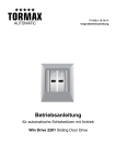
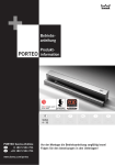
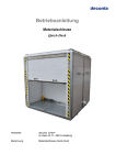
WN 058022 45532
01 11/11
DORMA
Montageanleitung
ES 410 / 420
Mounting instruction
ES 410 / 420
Montage- und
Bedienungsanleitung
Mounting instruction
Operation manual
WN 058022 45532
02 11/11
DORMA
2
Montageanleitung
ES 410 / 420
Mounting instruction
Inhaltsverzeichnis
11.2011 Contents
11/2011
Seite
Inhaltsverzeichnis - - - - - - - - - - - - - - - - - - - - - - - - - - - - 2
Contents
Sicherheitshinweise (D-GB) - - - - - - - - - - - - - - - - - - - - 3 - 6
For your safety (D-GB) - - - - - - - - - - - - - - - - - - - - - - - 3 - 6
EG Konformitätserklärung - - - - - - - - - - - - - - - - - - - - - - - 7
EC declaration of conformity - - - - - - - - - - - - - - - - - - - - - 7
EG Einbauerklärung - - - - - - - - - - - - - - - - - - - - - - - - - - - 8
EC declaration of incorporation - - - - - - - - - - - - - - - - - - - - 8
Technische Daten (D-GB) - - - - - - - - - - - - - - - - - - - - - - - 9
Technical data (D-GB) - - - - - - - - - - - - - - - - - - - - - - - - - 9
Erläuterungen der Pictogramme - - - - - - - - - - - - - - - - - - 10
Wichtige Hinweise vor der Montage - - - - - - - - - - - - - - - - 10
Explanation of symbols - - - - - - - - - - - - - - - - - - - - - - - - 10
Before starting with the installation - - - - - - - - - - - - - - - - 10
Montagevorbereitung:
Wichtige Einbaumaße - - - - - - - - - - - - Wandmontage linksöffnend (1-flügelig) - Wandmontage rechtsöffnend (1-flügelig) Wandmontage zweiflügelig - - - - - - - - - -
Preparation befor mounting:
Main dimensions - - - - - - - - - - - - - - - - - Wall mounting, right-handed single-leaf door
Wall mounting, left-handed single-leaf door Wall mounting double-leaf door - - - - - - - - -
-
-
-
-
-
-
-
11
12
12
12
Montage
Einbau des Antriebs - - - - - - - - - - - - - - - - - - - Einbau der Türflügel - - - - - - - - - - - - - - - - - - - Einstellung der Endanschläge - - - - - - - - - - - - - Einbau der bauseitige Verkleidung (LH bis 2,5 m) -
-
13
14
14
15
page
---------------------------------2
-
-
-
11
12
12
12
Prüfen der Türflügelbewegungen - - - - - - - - - - - - - 16
Elektrischer Anschluß - - - - - - - - - - - - - - - - - - - - 17
Installation instructions
Installing of operator - - - - - - - - - - - - - - - - - - - 13
Installing of sliding leaves - - - - - - - - - - - - - - - 14
Adjusting of the end stop - - - - - - - - - - - - - - - - 14
Mounting the cover (by others) - for clear passage
heights of up to 2.5 m) - - - - - - - - - - - - - - - - - 15
Controling of the Sliding leaves movements - - - - 16
Connection of main power - - - - - - - - - - - - - - - 17
Klemmendefinition- - - - - - - - - - - - - - - - - - - - - - - - - - - 18
Terminal definition- - - - - - - - - - - - - - - - - - - - - - - - - - - 18
Übersicht Peripheriegeräte - - - - - - - - - - - - - - - - - - - - - - 19
Overview peripheral options - - - - - - - - - - - - - - - - - - - - - 19
Anschlusspläne
Schleusenaufbau - - - - - - - - - - - - - - Anschlussplan Schleusensteuerung - - Anschlussplan Melder Allgemein - - - - Anschlussplan Treibriegelschaltkontakt -
Wiring diagram
Connection diagram for peripheral devices Airlock system and its wiring diagram - - - Wiring diagram for radar motion detector- Wiring diagram for latch bolt limit switch -
-
-
-
-
-
-
-
-
20
20
21
22
-
-
-
-
20
20
21
22
Inbetriebnahme - - - - - - - - - - - - - - - - - - - - - - - - - - - - - 23
Commissioning - - - - - - - - - - - - - - - - - - - - - - - - - - - - - 23
Bedienungsanleitung - - - - - - - - - - - - - - - - - - - - - - - - - 24
Operating instruction - - - - - - - - - - - - - - - - - - - - - - - - - 24
Wartung und Pflege - - - - - - - - - - - - - - - - - - - - - - - - - - 25
Care and maintenance - - - - - - - - - - - - - - - - - - - - - - - - 25
Einweisung - - - - - - - - - - - - - - - - - - - - - - - - - - - - - - - - 25
Briefing
Originalbetriebsanleitung
Translatioin of the original documentation
Dargestellt ist die Montage eine rechtsöffnende Tür.
Für eine linksöffnende Tür bitte spiegelbildlich arbeiten.
The mounting instruction is shown a left hand door.
Mirrored arragements apply for a right hand door.
- - - - - - - - - - - - - - - - - - - - - - - - - - - - - - - - 25
Montageanleitung
ES 410 / 420
Mounting instruction
WN 058022 45532
03 11/11
DORMA
1. Zu Ihrer Sicherheit
Diese Dokumentation enthält wichtige Anweisungen für den
sicheren Betrieb und die Montage. Lesen Sie diese
Anweisungen, bevor Sie den ES 410 / 420 verwenden.
Für Ihre Sicherheit ist es wichtig, allen beiliegenden
Anweisungen Folge zu leisten.
Eine falsche Montage kann zu schwerwiegenden
Verletzungen führen.
Die Verwendung von Steuerelementen, Einstellungen oder
Verfahren, die in dieser Dokumentation nicht beschrieben
sind, können elektrische Schläge, Gefahren durch
elektrische Spannungen/Ströme und/oder Gefahren durch
mechanische Vorgänge verursachen.
Die Unterlagen sind aufzubewahren und bei einer
eventuellen Weitergabe der Anlage mit zu übergeben.
In dieser Anleitung benutzte Symbole
ANMERKUNG Eine Anmerkung macht auf wichtige
Informationen aufmerksam, die Ihnen
die Arbeit erleichtern.
HINWEIS
Ein Hinweis warnt vor möglichen
Beschädigungen des Gerätes und
erläutert, wie diese verhindert werden
können.
ACHTUNG
Weist auf Gefahren hin, die zu
Sachschäden, Personenschäden oder
zum Tod führen können.
Bestimmungsgemäßer Gebrauch
Der ES 410 / 420 dient ausschließlich zum Öffnen und
Schließen von Schiebetüren mit einem zulässigen
Türflügelgewicht für ES 410 von maximal 200 kg,
für ES 420 von maximal 2 x 125 kg. Der
ES 410 / 420 ist nicht zur Verwendung an Flucht und
Rettungswegtüren einsetzbar.
Der ES 410 / 420 ist nicht zur Verwendung im
Außenbereich geeignet.
Die maximale Kabellänge externer Komponenten darf 30 m
nicht übersteigen.
Die Anbindung an den Türflügel erfolgt über Laufwagen
Haftungsbeschränkung
Der ES 410 / 420 darf nur gemäß seiner
bestimmungsgemäßen Verwendung eingesetzt werden.
Eigenmächtige Änderungen am ES 410 / 420 schließen
jede Haftung durch die DORMA GmbH + Co. KG für daraus
resultierende Schäden aus. Für die Verwendung von
Zubehör, das von DORMA nicht freigegeben ist wird keine
Haftung übernommen.
Sicherheitshinweise
Arbeiten an Elektroanlagen dürfen nur von geschulten
Fachkräften (Elektriker) ausgeführt werden.
· Kinder nicht mit dem ES 410 / 420 oder fest montierten
Regel- und Steuereinrichtungen spielen lassen.
Fernsteuerungen außerhalb der Reichweite von Kindern
halten.
· Führen Sie niemals Metallgegenstände in die Öffnungen
des ES 410 / 420 ein. Andernfalls besteht die Gefahr
eines elektrischen Schlages.
· Für Glastürflügel muss Sicherheitsglas verwendet
werden.
Wichtige technische Daten
· Spannungsversorgung
· Bauseitige Absicherung
· Betriebsgeräusch
· Temperaturbereich
· Nur für trockene Räume
relative Luftfeuchtigkeit
nicht kondensierend
Normen, Gesetze, Richtlinien und Vorschriften Allgemeines
· Der neueste Stand der allgemein gültigen und länderspezifischen Normen, Gesetze, Richtlinien und
Vorschriften ist einzuhalten.
DIN 18650
Der Hersteller (die Person, die den Einbau vornimmt) und
der Auftraggeber/Betreiber müssen bei der Planung der
Anlage gemeinsam eine individuelle Risikobeurteilung
durchführen.
Wir verweisen hierzu auf das zur Unterstützung der
Durchführung zur Verfügung stehende Formular
"Risikobewertung", Sie erhalten es unter dem Register
PRODUKTE auf unserer Internetseite www.dorma.de.
Gefahrenstellen an Schließkanten
An automatischen Türen können an den verschiedenen
Schließkanten Quetsch-, Scher-, Stoß- und
Einzugsgefahren bestehen.
Nebenschließkante
Hauptschließkante
Je nach baulicher Gegebenheit, Türvariante und
Absicherungsmöglichkeit können Restgefahren (z. B.
Quetschen, kraftbegrenztes Anstossen) nicht
ausgeschlossen werden.
Besonderes Absicherungserfordernis hinsichtlich
schutzbedürftiger Personen
Soweit die Risikobewertung die Gefahr eines im Hinblick
auf ein Gesundheits- oder Verletzungsrisiko inakzeptablen
Anstoßes eines Türnutzers ergibt, muss eine Absicherung
durch eine Schutzeinrichtung (Anschluss einer Sensorleiste)
ergänzend erfolgen. Dies ist insbesondere dann zu
berücksichtigen, wenn im Türbereich mit besonders
schutzbedürftigen Personen (Kinder, ältere Personen oder
Behinderte) gerechnet werden muss.
Recycling und Entsorgung
Sowohl der ES 410 / 420 als auch die
Verpackung bestehen zum überwiegenden Teil
aus recyclefähigen Rohstoffen.
Der ES 410 / 420 wie auch das Zubehör
gehören nicht in den Hausmüll.
Sorgen Sie dafür, dass das Altgerät und ggf.
vorhandenes Zubehör einer ordnungsgemäßen
Entsorgung zugeführt werden.
Beachten Sie dabei die geltenden nationalen gesetzlichen
Vorschriften.
230 V AC
16 A
< 70 dB(A)
0° bis 40°
max. 93%
3
WN 058022 45532
04 11/11
DORMA
Montageanleitung
ES 410 / 420
Mounting instruction
Sicherheit bei der Montage
· Der Arbeitsplatz ist gegen unbefugtes Betreten zu
sichern. Herunterfallende Teile oder Werkzeuge können
zu Verletzungen führen.
· Der ES 410 / 420 muss vor Wasser und anderen
Flüssigkeiten geschützt werden.
· Befestigungsart und Befestigungsmittel, wie z.B.
Schrauben und Dübel, müssen auf jeden Fall den
baulichen Gegebenheiten angepasst werden
(Stahlkonstruktion, Holz, Beton usw.).
· Die hier beschriebene Montage des ES 410 / 420 ist ein
Beispiel. Bauliche oder örtliche Gegebenheiten,
vorhandene Hilfsmittel oder andere Umstände können
eine andere Vorgehensweise sinnvoll machen.
· Im Anschluss an die Montage sind die Einstellungen und
die Funktionsweise des ES 410 / 420 und der
Schutzeinrichtungen auf einwandfreien mechanischen
Zustand zu überprüfen.
· Nur qualifizierte Fachleute dürfen das
Netzanschlussgehäuse öffnen.
· Vor Abnahme der Schutzhaube den ES 410 / 420
spannungsfrei schalten. Netzstecker ziehen oder bei
Festanschluss, Sicherung ausschalten.
· Fassen Sie das Netzkabel nur am Stecker und niemals am
Kabel an, um es aus der Steckdose zu ziehen.
Sicherheit bei der Inbetriebnahme
· Der Schutzleiter muss angeschlossen sein.
· Die Sicherheitssensorik soll angeschlossen sein
(siehe Inbetriebnahmeanleitung).
· Antriebseinheit und Fahrflügel sind korrekt miteinander
verbunden
· Die Endanschläge sind so eingestellt, dass die Fahrflügel
bei max. Öffnungsweite die Endanschläge berühren. Die
Fahrflügel und die Standflügel bei geschlossener Tür
nicht mit den Dichtungsprofilen zusammenstoßen.
· Fahrflügel müssen leichtgängig sein.
· Die separat gelieferten Teile wie Programmschalter, NOTAUS Schalter und Impulsgeber (Radarmelder,
NACHT/BANK-Schlüsseltaster) müssen montiert und
angeschlossen sein.
· Akkueinheit ist eingebaut (optional)
Überprüfung und Abnahme
Der ES 410 / 420 ist vor der ersten Inbetriebnahme und
nach Bedarf, jedoch mindestens einmal jährlich, von einem
Sachkundigen zu prüfen und ggf. zu warten.
Die Überprüfung und Abnahme müssen anhand des
Prüfbuchs von einer durch DORMA ausgebildete Person
durchgeführt werden.
Die Ergebnisse sind gemäß DIN 18650-2 zu dokumentieren
und für mindestens 1 Jahr durch den Betreiber
aufzubewahren.
Es empfiehlt sich mit DORMA einen Wartungsvertrag
abzuschließen.
4
Einweisung
Nach erfolgreicher Einstellung, Inbetriebnahme und
Funktionsprüfung der Türanlage, ist die Bedienungsanleitung dem Betreiber auszuhändigen und eine
Einweisung durchzuführen.
Türverhalten bei unterschiedlichen Witterungsverhältnissen
Die Sicherheitssensoren der Türanlage (InfrarotLichtvorhänge) dienen der Absicherung des
Durchgangsbereichs. Höchste Priorität hat bei der
Einstellung der Empfindlichkeit der Sensoren der
Personenschutz. Insbesondere bei wechselnden
Witterungseinflüssen (Regen- oder Schneeschauern), bei
umherfliegendem Laub oder auch direkter
Sonneneinstrahlung auf reflektierenden Bodenbelägen, kann
es sporadisch zu Fehldetektionen der Sensoren kommen.
Diese haben unter Umständen eine Öffnung der Tür von bis
zu einer Minute zur Folge. Dieser Offenstand der Türanlage
ist durch eine Normvorgabe festgelegt und völlig normal. Er
dient ausschließlich der Sicherheit der Türnutzer.
Wartung
Wartungsarbeiten dürfen nur im spannungsfreien Zustand
durchgeführt werden. Netzstecker ziehen oder bei
Festanschluss Sicherung ausschalten.
Pflege
Während der Reinigung den Programmschalter in Stellung
AUS bzw. DAUERAUF schalten, um ungewollte
Fahrbewegungen zu vermeiden.
Die gesamte Schiebetüranlage (Aluminium, Glas,
Verkleidung) kann mit einem feuchten Tuch und
handelsüblichen Reiniger gesäubert werden.
Verwenden Sie ein trockenes Tuch zur Reinigung der
Lichtschranken. Bodenführungen reinigen.
Lassen Sie kein Wasser oder andere Flüssigkeiten auf oder
in den ES 410 / 420 gelangen.
Führen Sie niemals Metallgegenstände in die Öffnungen am
ES 410 / 420 ein. Andernfalls besteht die Gefahr eines
elektrischen Schlages.
Verschleißteile
Folgende Teile sind Verschleißteile und müssen in
regelmäßigen Abständen geprüft und ggf. ausgetauscht
werden:
· Die Antriebseinheit
· Die Laufrollen der Laufwagenköpfe
· Die Endanschläge
· Der Potentialausgleich
· Die Umlenkrolle
· Der Zahnriemen
Es dürfen nur Originalersatzteile eingesetzt werden.
Montageanleitung
ES 410 / 420
Mounting instruction
WN 058022 45532
05 11/11
DORMA
1. For your safety
This documentation contains important information
regarding the mounting and the safe operation of the door
system.
Please read these instructions carefully before using the
ES 410 / 420.
It is important for your personal safety to abide by all
enclosed instructions.
An incorrectly performed installation might cause serious
injuries.
Using control elements, making adjustments or performing
procedures that are not described in this documentation
might cause electric shocks, danger caused by electric
voltage/current and/or danger due to mechanical incidents.
Please keep these documents for further reference and hand
them over to the person in charge in case the system is
transferred to another party.
Explanation of symbols
NOTE
This symbol underlines important
information that may facilitate your
work.
REMARK
This symbol warns you of possible
system damage and explains how to
avoid this damage.
WARNING
This symbol indicates dangers that
might cause personal or material
damage or even kill people.
Intended application
The ES 410 is only designed to open and close interior
sliding doors with an admissible door panel up to 200 kg,
the ES 420 is only designed to open and close interior
sliding doors with an admissible door panels up to 125 kg.
The ES 410 / 420 is not suitable for application in
emergency exits and escape routes
The ES 410 / 420 is not suitable for application at exterior
doors.
The maximum cable length for external components must
not exceed 30 m.
The system is connected to the door leaf via carriages.
Limitation of liability
The ES 410 / 420 may only be used according to its
specified intended application.
The DORMA GmnH + Co. KG will not accept any liability for
damage resulting from unauthorised modifications of the
ES 410 / 420. Furthermore components/accessories that
have not been approved by DORMA are exempted from
liability.
Safety instructions
Work on electrical equipment may only be performed
by properly qualified staff (electricians).
· Do not allow children to play with the
ES 410 / 420 or its adjustment and control devices.
· Keep remote controls out of reach of children.
· Never stick metal objects into the openings of the
ES 410 / 420; otherwise you might sustain an electric
shock.
· If the ES 410 / 420 is mounted onto a metal door leaf,
you have to earth (ground) the door leaf properly.
· Glass door leaves have to be made of safety glass.
Important technical data
· Power supply
· Fuse (by others)
· Operating noise
· Temperatur range
· Only suitable for dry environments
relative humidity
non-condensing
Standards, laws, codes and regulations
· The latest versions of the common and country-specific
standards, laws, codes and regulations have to be
observed.
DIN 18650 (German Industrial Standard)
During the planning of the door system, the manufacturer
(the person installing the system) and the
commissioner/facility operator have to perform an individual
risk assessment (together).
Please refer to our homepage www.dorma.com and consider
the provided “risk assessment form” under PRODUCT for
further assistance when performing your individual risk
assessment.
Danger spots at closing edges
Automatic doors might cause hazards by crushing,
shearing, hitting and drawing-in at the different
closing edges.
Secondary
closing edge
Main
closing edge
Residual risk
Depending on the structural conditions, the prevailing door
version and the available safety equipment, residual risks
such as crushing and hitting (with a limited force) cannot be
excluded.
Special requirements regarding the protection of people in
need of protection
In case the risk assessment reveals that there is a health
risk or risk of injury caused by the door hitting a person
using the door with an unacceptable force, an additional
protection with the aid of appropriate safety equipment
(connection of a safety sensor) is required.
This is especially necessary when people in need of
protection (children, elderly people or disabled people) use
the door
Recycling and disposal
Both the ES 410 / 420 and its packing mainly
consist of recyclable raw material.
The ES 410 / 420 and the respective
accessories must not be disposed of as domestic
waste.
Please ensure that the old appliance and the
respective accessories (if available) are properly
disposed of.
Please abide by the prevailing national statutory provisions.
230 V
16 A
< 70 dB(A)
0° - 40°
max. 93%
5
WN 058022 45532
06 11/11
DORMA
Montageanleitung
ES 410 / 420
Mounting instruction
Safety during mounting
·The working area has to be secured against unauthorised
access from other people. Falling items or tools might
cause injuries.
· The ES 410 / 420 has to be secured against water and
other liquids.
· In any case, the way of mounting and the mounting
equipment, like for example screws and wall plugs,
have to be adequate with regard to the structural
conditions (steel structure, wood, concrete etc.).
· The mounting of the ES 410 / 420 described herein is
only an example. Structural or local conditions,
available tools or other conditions might suggest a
different approach.
· Following the successful installation of the system, the
settings and the proper function of the
ES 410 / 420 and the safety equipment have to be
checked.
· Only specially qualified staff may open the power
supply housing.
· Disconnect the ES 410 / 420 from power supply (deenergise the system) before removing the cover of the
power supply housing. Remove mains plug or switch off
fuse (with permanent power supply).
· Always pull at the plug and never at the cable when
unplugging the power supply.
Safety during commissioning
· The protective earth conductor has to be connected.
· The safety sensors are to be connected (see
commissioning instructions).
· The operator and the active panels are properly linked.
· The end stops are adjusted so that the sliding panels
meet the end stops when the system is adjusted to its
maximum opening width
· Furthermore the sealing profiles of the active panels
and the passive panels must not collide while the door
is closed
· Separately supplied components such as the program
switch, the EMERGENCY OFF pushbutton and
activators (radar motion detectors, NIGHT-/BANK key
switches) have to be mounted and connected.
· Ensure that the door leaves run smoothly
· The rechargeable battery pack has been installed
(optional).
Inspection and system approval
Before the first commissioning and depending on
requirements, however, at least once a year,
the ES 410 / 420 has to be inspected by a properly
qualified technician and serviced if required.
A person trained by DORMA has to perform the inspection
and approve the system with the aid of the inspection
book.
The respective results have to be documented in
accordance with DIN 18650-2 and the facility operator
has to keep these documents for at least one year.
We would recommend taking out a maintenance
agreement with DORMA.
6
Briefing
Following the adjustment, commissioning and functional
testing of the door system, the operating instructions have
to be handed over to the facility operator and a briefing
has to be made.
Behaviour of door system during varying weather
conditions
The safety sensors (infrared light curtains) are designed to
safeguard the passage area. When it comes to adjusting
the sensitivity of the sensors, the protection of people
always has top priority. From time to time, changing
climatic conditions (such as rain or snow), flying leaves or
direct sunlight (reflected by certain floor finishes) may
accidentally trigger the sensors. As soon as the light
curtains have been triggered, the door may remain open
for up to one minute – as required by a certain standard.
This is only a standard procedure with the only purpose to
protect the users of the door system.
Maintenance
The system has to be de-energised (disconnected from
power supply) before performing any kind of maintenance
work.
Remove the power plug or switch off the fuse (with
permanent power supply).
Care
Set program switch to OFF or PERMANENT OPEN mode
in order to avoid an undesired movement of the door while
cleaning the system.
You may clean the complete door system (aluminium,
glass, cover) with a damp cloth and a standard
commercial cleaning agent
You should not use scouring agents for cleaning purposes
as they might damage the surface finish.
Use a dry cloth to clean the light barriers. Clean the floor
guides
Ensure that no water or other liquids drop on or into the
ES 410 / 420.
Never stick metal objects into the openings of the
ES 410 / 420 otherwise you might sustain an electric
shock.
Wear parts
The following wear parts have to be inspected at regular
intervals during the maintenance of the door system and
must be replaced as required in order to ensure the proper
functioning of the door system:
• The operator
• The pulleys of the carrier heads
• The end stops
• The equipotential bondings
• The pulley
• The toothed belt
Only use original spare parts.
Montageanleitung
ES 410 / 420
Mounting instruction
WN 058022 45532
07 11/11
DORMA
7
WN 058022 45532
08 11/11
DORMA
8
Montageanleitung
ES 410 / 420
Mounting instruction
D
TÜV Zertifikat
CE-Kennzeichnung
Sonderfunktionen
Ohne Netzspannung:
manuell zu Öffnen und Schließen
Push & GO Funktion
(wird die Tür manuell geöffnet, wird ein
automatischer Öffnungsimpuls ausgelöst)
Schleusensteuerung für bis zu 3 Türanlagen
Separater Meldeeingang zur Ansteuerung
durch Brandmeldeanlagen (BMA)
Einstellungen
Öffnungsgeschwindigkeit
Schließgeschwindigkeit
Offenhaltezeit:
Teiloffen
Bettenöffnung
Daten und Merkmale
Öffnungsweite, in mm, 1-flügelig
Öffnungsweite, in mm, 2-flügelig
Türgewicht, in kg max., 1-flügelig
Türgewicht, in kg max., 2-flügelig
ES 410
1 x 200
700 - 3000
0s
·
·
·
·
·
·
-
60 s
min. - max.
10 cm/s - 50 cm/s
10 cm/s - 50 cm/s
250 VA
IP20
·
·
0° - 40°
2 x 125
800 - 3000
ES 420
TÜV Certificate
CE-approval
Features and benefits
Without power supply:
manual opening and closing
Push & Go function (an automatic opening
pulse is triggered when the door is manually
opened)
Airlock control for up to 3 door systems
Separate input for control via fire detection
system
Settings
Opening speed
Closing speed
Hold-open time:
Partial Open
Bed Function of Nurse-Bed Function
Door parameters
Clear passage width, in mm, single-leaf door
Clear passage width, in mm, double-leaf door
Max. weight in kg, single-leaf door
Max. weight in kg, double-leaf door
Supply voltage
Fuse
Power supply for external accessories
Power consumption
max.
Class of protection
Compliant with the Low Voltage Directive
Manufactured to ISO 9001:2000
Temperatur range
Anschlußspannung
Absicherung
Spannungsversorgung für externe Geräte
Leistungsaufnahme
max.
Schutzart
Geprüft nach Niederspannungsrichtlinien
Fertigung nach ISO 9001:2000
Temperaturbereich
230 V +/- 10% / 50/60 Hz
16 A
24 V DC / max. 300 mA
180 W
Technical data
Technische Daten
GB
WN 058022 45532
09 11/11
DORMA
Montageanleitung
ES 410 / 420
Mounting instruction
9
Montageanleitung
ES 410 / 420
Mounting instruction
WN 058022 45532
10 11/11
DORMA
10
Erläuterung der Pictogramme
Explanation of symbols
Montageanleitung
Installation instruction
Klemmendefinition
Connection diagram
Anschlusspläne
Wiring diagrams
Informationen
Information
Wichtige Hinweise vor der Montage
Before starting with the installation
Bilder die sich speziell auf linksöffnende Türen beziehen sind
mit Anhang “A” numeriert wie z.B.: 1A 2A 3A
Pictures that are especially for left-opening doors are marked
with an "A” at the end like for example: 1A 2A 3A
Bilder die sich speziell auf rechtsöffnende Türen beziehen sind
mit Anhang “B” numeriert wie z.B.: 1B 2B 3B
Pictures that are especially for right-opening doors are marked
with a "B” at the end like for example: 1B 2B 3B
Bilder die sich speziell auf doppelflügelige Türen beziehen
sind mit Anhang “C” numeriert wie z.B.: 1C 2C 3C
Pictures that are especially for double-leaf doors are marked
with a "C” at the end like for example: 1C 2C 3C
Arbeiten an Elektroanlagen dürfen nur von geschulten
Fachkräften ausgeführt werden.
Work on electrical equipment may only be performed by
properly qualified electricians.
Für die Stromversorgung muss ein bauseitiger Anschluss mit
Standardabsicherung vorhanden sein.
Power supply (by others) with a standard fuse protection is
required.
Das Anschlußkabel muß doppelt isoliert sein:
z.B.: NYM. Es darf keine Stegleitung verwendet werden
The connection cable must be double insulated, for example:
NYM. Do not use flat webbed house wires
Die maximale Kabellänge externer Komponenten darf 30 m
nicht überschreiten.
The maximum cable length for external accessories must not
exceed 30 m.
Die Anlage muss mit einer bauseitigen Verkleidung versehen
werden.
Nur wenn diese in eine Bauhöhe von mindestens 2,5 m
eingesetzt wird, kann man auf diese Verkleidung verzichten.
The system must be equipped with a cover that has to be
provided by others.
The cover is required unless the system is installed in an
installation height of at least 2.5 m.
Montageanleitung
ES 410 / 420
Mounting instruction
WN 058022 45532
11 11/11
DORMA
min. 60
270
65
max. 6000
300
33
200
Flügelweg
Driving path
132
100
Türflügel
Door panel
65
min. 50
Befestigungsplatte
Mounting plate 15 bis/up to30
10
1A
32,5
10 10
min. 60
270
max. 6000
300
Türflügel
Door panel
100
200
Flügelweg
Driving path
Türflügel
Door panel
0
6 bis/up to 8
1B
400
200
Flügelweg
Driving path
min. 60
270
max. 6000
100 100
Türflügel
Door panel
200
Türflügel
Door panel
Flügelweg
Driving path
1C
11
Montageanleitung
ES 410 / 420
Mounting instruction
WN 058022 45532
12 11/11
DORMA
n x 400 (m < 100 kg) Ø8
n x 200 (m > 100 kg) Ø8
400 (200)
ES 410
2A
min. 55
max. 70
Ø8
Lichte Weite
Clear opening width
Türflügel / Door panel
ES 410
n x 400 (m < 100 kg) Ø8
n x 200 (m > 100 kg) Ø8
50
400 (200)
min 65
33
min. 55
max. 70
ES 410
Ø8
Lichte Weite + min. 250
Clear opening width + min. 250
Lichte Weite
Clear opening width
Türflügel / Door panel
2B
ES 410
n x 400 (m < 100 kg) Ø8
n x 200 (m > 100 kg) Ø8
50
400 (200)
33
Ø8
Lichte Weite
2
Opening width
2
2C
min 65
33
Lichte Weite + min. 250
Clear opening width + min. 250
12
50
min 65
min. 55
max. 70
Lichte Weite
Opening width
Türflügel / Door panel
Türflügel / Door panel
ES 420
Lichte Weite + min. 250
2
Clear opening width + min. 250
2
ES 420
Montageanleitung
ES 410 / 420
Mounting instruction
WN 058022 45532
13 11/11
DORMA
min. 15
50
33
Ø8
3
4A
4B
4C
13
Montageanleitung
ES 410 / 420
Mounting instruction
WN 058022 45532
14 11/11
DORMA
5A
Türflügel
Door panel
6 bis/to 8
5A/B/C
5B
5C
1.
1.
2.
2.
3.
3.
6
0
0
7
2.
8
14
1.
2.
1.
Montageanleitung
ES 410 / 420
Mounting instruction
WN 058022 45532
15 11/11
DORMA
max. 0,5
9
Bauseits / By others
min. 250
LH = max. 2500
10A
Bauseits / By others
min. 250
LH = max. 2500
10B
Bauseits / By others
min. 250
LH = max. 2500
10C
15
Montageanleitung
ES 410 / 420
Mounting instruction
WN 058022 45532
16 11/11
DORMA
min. 250
11A
min. 250
11B
min. 250
11C
16
min. 250
Montageanleitung
ES 410 / 420
Mounting instruction
WN 058022 45532
17 11/11
DORMA
2.
1.
Bauseitige Erdung
PE connection supplied by others
12
RESET 2.
1.
3.
Anschlussplatine
Connection board
13
17
Montageanleitung
Klemmendefinition
ES 410 / 420
Mounting
instruction
terminal connections
WN 058022 45532
18 11/11
DORMA
230 VAC
1
6
1
X1
X2
13
7
2
28 VAC
3
5
4
Beschreibung und
Klemmendefinition
Description and
Connection diagram
24
GB
1
LED Spannungsanzeige
LED voltage display
2
Resettaster
Reset pushbutton
3
Busstecker
Bus connector
4
Programmierschnittstelle
Program interface
5
Anschlußstecker für externe
Anschlußklemmen X1 und X2
Connector for external terminal strip X1 and X2
GND
DAUERAUF (Schliessimpuls)
PERMANENT OPEN (closing pulse)
GND
TEIL-AUF (Schliessimpuls)
PARTIAL OPEN (closing pulse)
GND
VOLL-AUF (Schliessimpuls)
COMPLETELY OPEN (closing pulse)
GND
SPERRUNG (der Steuerung bei
Schleusenbetrieb
TREIBRIEGELKONTAKT (Öffnerkontakt)
LOCKING DEVICE(blocking of the controller
when airlockfunktion)
LATCH BOLT CONTACT (normally closed contact)
SONDEREINGANG (Schliesskontakt)
SPECIAL INPUT (normally open contact)
TÜR ZU (Wechsler) Schleuse
DOOR CLOSED (changeover contact) Airlock
TÜR ZU (Wechsler) Schleuse
DOOR CLOSED (changeover contact) Airlock
Lichtschranke (Öffnerkontakt)
Light barrier (normally closed contact)
6
7
18
D
12
X1
1
2
3
4
5
6
7
8
9
10
11
12
X2
13
14
15
16
17
18
19
20
21
22
23
24
GND
GND
GND
+ 24 V DC
GND
+ 24 V DC
C
NC
NO
C
NC
NO
GND
Peripheriegeräte
Montageanleitung
ES 410 / 420
Peripheral instruction
devices
Mounting
WN 058022 45532
19 11/11
DORMA
6
7
8
5
4
3
2
1
1
Systemkomponente
System component
Systemkabel
System cable
1
Lichtschranke / Sicherheitssensor
Light barrier / safety sensor
4 x 0,5
2
Impulsgeber “Auffahren”
Activator "open door”
2 x 0,5
3
Impulsgeber “TEILAUF”
Activator "PARTIAL OPEN”
2 x 0,5
4
Impulsgeber “DAUERAUF”
Activator "PERMANENT OPEN”
2 x 0,5
5
Treibriegelkontakt
Contact for limit switch
2 x 0,5
6
Bewegungsmelder Aussen
External motion detector
4 x 0,5
7
Bewegungsmelder Innen
Internal motion detector
4 x 0,5
8
Steuerung
ES 410 / ES 420
Control unit
Blockiert Anschlüsse 1 bis 6
Blocks connection 1 to 6
19
Montageanleitung
Schleusensteuerung
ES 410 / 420
Airlock control
Mounting
instruction
WN 058022 45532
20 11/11
DORMA
1.
Schleusensteuerung
Airlock control
Steuerung:
Control unit:
X1
1
2
3
4
5
6
1.
7
8
9
10
11
12
Anschlussplatine
Connection board
X2
13
14
15
16
17
18
19
20
21
22
23
24
2.
2.
Steuerung:
Control unit:
X1
1
2
3
4
5
6
3.
7
8
9
10
11
12
3.
Steuerung:
Control unit:
X1
1
2
3
4
5
6
7
8
9
10
11
12
20
Anschlussplatine
Connection board
X2
13
14
15
16
17
18
19
20
21
22
23
24
Anschlussplatine
Connection board
X2
13
14
15
16
17
18
19
20
21
22
23
24
Montageanleitung
Anschlußplan
ES 410 / 420
Mounting
instruction
Wiring diagram
WN 058022 45532
21 11/11
DORMA
Anschlußplan Melder
Wiring diagram for radar motion detector
Plan de raccord pour le radar
Steuerung:
Control unit:
Anschlussplatine
Connection board
X1
1
2
3
4
5
6
7
8
9
10
11
12
Außenmelder
radar motion detector outside
X2
24 V DC
13
14
15
16
17
18
19
20
21
22
23
24
Innenmelder
radar motion detector inside
24 V DC
Beschreibung und
Klemmendefinition
D
GB
Description and
connection diagram
Steuerung
Control unit
Melder innen und aussen
Melder innen und aussen
Radar inside and outside
Radar inside and outside
Melder innen und aussen
Melder innen und aussen
Radar inside and outside
Radar inside and outside
Melder
Radar
Steuerung
Steuerung
Control unit
Control unit
X1
1
2
3
4
5
6
7
8
9
10
11
12
GND
X2
13
14
15
16
17
18
19
20
21
22
23
24
GND
+ 24 V DC
GND
+ 24 V DC
21
Montageanleitung
Anschlußplan
ES 410 / 420
Mounting
instruction
Wiring diagram
WN 058022 45532
22 11/11
DORMA
Anschlußplan Treibriegelkontakt
Wiring diagram of contact for limit switch
Steuerung:
Control unit:
Anschlussplatine
Connection board
X1
1
2
3
4
5
6
7
8
9
10
11
12
Treibriegelkontakt
Contact for limit switch
X2
13
14
15
16
17
18
19
20
21
22
23
24
Beschreibung und
Klemmendefinition
D
GB
Description and
connections diagram
Steuerung
Control unit
Treibriegelkontakt
Treibriegelkontakt
Contact for limit switch
Contact for limit switch
Treibriegelkontakt
Contact for limit switch
X1
1
2
3
4
5
6
7
8
9
10
11
12
22
GND
Montageanleitung
ES 410 / ES 420
Mounting instruction
WN 058022 45532
23 11/11
DORMA
Inbetriebnahme
(Softwareversion V6.70)
Work on electrical equipment may only be
performed by properly qualified staff.
Please wire and check all electrical connections
before installing the system on site.
Die Anlagen ES 410 und ES 420 dürfen nur im
Innenbereich eingesetzt werden.
ES 410 and ES 420 are only suitable for
application on interior doors
Die Inbetriebnahme per Autoparametrierung
muss nach erfolgter Montage oder wenn eine
Änderung der Öffnungsweite erfolgt ist, ausgeführt werden. Unter Umständen hilft eine
Autoparametrierung auch bei unerklärlichem
Verhalten der Anlage.
Ein PC mit Bediensoftware kann hilfreich sein,
um sich den Status anzeigen zu lassen, Parameter einzustellen und die Autoparametrierung zu
starten.
The system has to be commissioned via the
automatic parameterisation after it has been
installed and whenever the setting of the opening
width has been changed. The automatic
parameterisation may also be useful whenever the
system behaves strangely.
With a PC and the respective user software, you
may have the system status indicated, adjust
parameters or start the automatic
parameterisation.
Anlage auf Sauberkeit überprüfen.
Schließbereich der Tür freihalten.
Kontrollieren ob nötige Brücken eingesetzt sind,
z.B. Riegelkontakt und Lichtschranke.
Die restlichen Eingänge sollen nicht aktiv sein.
Tür in Offenposition schieben.
2.
Versorgungsspannung anschließen.
3.
Reset-Knopf für gut 10 Sekunden drücken bis
Relais klickt (Bild 13) oder am PC
„Autoparametrierung“ auswählen.
5.
(Softwareversion V6.70)
Arbeiten an Elektroanlagen dürfen nur von
geschulten Fachkräften ausgeführt werden.
Vor dem Einbau vor Ort bitte elektrische
Anschlüsse verdrahten und prüfen.
1.
4.
Commissioning
Die Tür führt nun die nötigen Bewegungen in der
folgenden Sequenz durch:
Tür fährt ca. 15 cm in Schliessrichtung und hält
an.
Tür öffnet in Schnellfahrt und fährt hart auf den
Stopper auf, danach wird die Strecke in
Zu-Richtung langsam abgefahren.
Nach kurzer Pause wird eine Öffnung mit starkem
Abbremsen (zur Gewichtsbestimmung) ausgelöst,
dann fährt die Tür langsam bis zum Anschlag
weiter.
Nach kurzer Pause wird eine Schließung mit
starkem Abbremsen (ebenfalls zur Gewichtsbestimmung) ausgeführt, dann öffnet die Tür
langsam bis zum Anschlag.
Hier endet die Autoparametrierung und die
Referenzfahrten werden gestartet.
Es folgen zwei Bewegungen in Langsamfahrt als
Referenzfahrt. Nach erfolgreicher Referenzfahrt
schließt der Flügel und die Anlage ist bereit.
Die Offenhaltezeit der Türanlage kann problemlos
manuell eingestellt werden.
“Voll-Auf“-Taster drücken und gedrückt halten.
Während die Tür sich öffnet auch den Taster
„Teil-Auf“ drücken und beide gedrückt halten.
Nachdem die Tür ganz offen ist, müssen beide
Impulsgeber weiter solange aktiv gehalten
werden, wie die Tür offen bleiben soll.
Diese "Offenhaltezeit" ist ab jetzt eingestellt und
aktiv sobald die Tür ganz geöffnet wird.
1.
Check if the system is clean.
Make sure that there are no obstructions within
the door’s closing range.
Check if all required jumpers are properly
positioned (such as bolt contact and light
barrier).
The remaining inputs should not be activated.
Move the door to “open” position.
2.
Connect the power supply.
3.
Press and hold the reset key for at least 10
seconds until you hear the relay click (Picture 13)
or select the “Automatic parameterisation” via
the PC.
4.
The door now performs the required movements
in the following order:
First the door closes by approx. 15 cm before it
stops.
Then it opens at high speed and crashes into the
stopper. After that the door slowly travels in
closing direction until it has reached its “closed”
position.
Following a short rest period, the door opens,
stops rapidly (in order to determine the door
weight) and then slowly moves on until it has
reached its full opening width.
After another short break, the door closes, stops
rapidly (in order to determine the door weight)
and then slowly opens to its full opening width.
Now the automatic parameterisation is completed
and the door performs two reference cycles at low
speed. After the reference cycles have been
performed, the door closes and the system is
ready for operation.
5.
The hold-open time may easily be adjusted by
hand. Press the activators to open the door and
to adjust the PARTIAL OPEN function
simultaneously while the door performs an
opening cycle. As soon as the door has reached
its full opening width, press and hold both
activators for as long as you want the door to
remain open (hold-open time).
60
23
WN 058022 45532
24 11/11
DORMA
6.
Montageanleitung
ES 410 / ES 420
Mounting instruction
Die einstellbaren Parameter können jetzt
individuell per Software (PDA oder Laptop)
eingestellt werden. Kontaktieren Sie Ihren
Verkaufsberater um diese zu bekommen.
The new hold-open time has now been adjusted
and is applicable whenever the door is opened to
its full opening width.
6.
All adjustable parameters are now individually
adjustable with the aid of the software (PDA or
laptop). Please contact you sales representative in
order to get the software.
Bedienungsanleitung
Instruction manual
Die Steuerungen der ES 410 und ES 420 werden bei
der Fertigung im Werk geprüft und mit Prüfnummern
versehen.
Jede Prüfung wird protokolliert.
Dann wird je eine Steuerung in eine Anlage verbaut
und der Zusammenbau auf Funktionsfähigkeit
überprüft.
Erst dann dürfen die fertige Anlagen das Werk zum
Kunden verlassen.
The ES 410 and ES 420 control units are thoroughly
tested during production and respective test numbers
are allocated.
Furthermore, there is a protocol for every test.
Then the respective control unit is installed before the
complete system is tested for proper functioning.
Only systems that have passed this procedure will
leave our premises.
1. In der Nähe der Tür befinden sich drei Taster zum
öffnen der Tür.
- Dauer-Auf
- Teil-Auf (Schwesternschaltung)
- Voll-Auf (Bettenschaltung)
Bei Dauerauf wird die Tür per Taster geöffnet und
bleibt solange auf bis der Taster wieder betätigt wird.
Bei Teiloffen geht die Tür (bei Tasterbetätigung) nur
soweit auf, dass eine Person durchschreiten kann und
schließt nach der eingestellten Offenhaltezeit.
Bei der vollen Öffnung öffnet sich die Tür ganz (bei
Tasterbetätigung) und schließt nach der eingestellten
Offenhaltezeit.
2. Bei Schleusenbetrieb sind die Antriebe so verkabelt, dass die Öffnung einer Tür die Sperrung der
andere Tür zur Folge hat. Diese lässt sich erst wieder
öffnen, wenn die zuerst betätigte Tür wieder geschlossen ist.
Es können bis zu drei Türen in Schleusenschaltung
miteinander verbunden sein.
3. Die Offenhaltezeit der Türanlage kann
problemlos manuell eingestellt werden.
“Voll-Auf“-Taster drücken und gedrückt halten.
Während die Tür sich öffnet auch den Taster „TeilAuf“ drücken und beide gedrückt halten.
Nachdem die Tür ganz offen ist, müssen beide
Impulsgeber weiter solange aktiv gehalten werden, wie
die Tür offen bleiben soll.
Diese Offenhaltezeit ist ab jetzt eingestellt und aktiv
sobald die Tür ganz geöffnet wird.
4. Wie weit sich die Tür bei “Teilauf” öffnet, wird per
PDA eingestellt.
5. Die Offenhaltezeit der Tür bei “Teil-Auf” und bei
“Voll-Auf” werden unabhängig voneinander per PDA
eingestellt.
1. In the close range of the door system, there are
three pushbuttons to open the door:
- one to adjust the PERMANENT OPEN function
- one for the PARTIAL OPEN function (nurse opening
of Nurse-Bed-Function)
- and one to adjust the full opening width (bed
opening of Nurse-Bed-Function).
The PERMANENT OPEN mode is activated via
pushbutton and the door will remain open until the
respective pushbutton is activated a second time.
In PARTIAL OPEN mode (also activated via
pushbutton), the door opens and creates a passage
width that is sufficiently big for one person and closes
on expiry of the adjusted hold-open time.
When the bed opening of the Nurse-Bed-Function is
activated (via pushbutton), the door opens to its full
opening width and closes on expiry of the adjusted
hold-open time.
2. In airlock mode, the operators are wired so that as
soon as one door is opened, the other door is disabled
and cannot be opened until the first door has reached
“closed” position.
An airlock system may consist of up to three doors.
3. The hold-open time may easily be adjusted by
hand. Press the activators to open the door and to
adjust the PARTIAL OPEN function simultaneously
while the door performs an opening cycle. As soon as
the door has reached its full opening width, press and
hold both activators for as long as you want the door
to remain open (hold-open time).
The new hold-open time has now been adjusted and
is applicable whenever the door is opened to its full
opening width.
4. The opening width for the PARTIAL OPEN function
is adjusted via the PDA.
5. The hold-open time for the PARTIAL OPEN mode
and for the bed opening of the Nurse-Bed-Function
(full opening width) are also individually adjustable via
the PDA.
61
24
Montageanleitung
ES 410 / ES 420
Mounting instruction
WN 058022 45532
25 11/11
DORMA
Following a power failure
Nach einen Netzausfall
• Die Eingangstaster (Dauer-Auf, Teil-Auf bzw. VollAuf) der Tür sind inaktiv.
• Tür in Offenposition schieben.
• Netzspannung anlegen.
• Einen der Eingangstaster kurz aktivieren.
• Die Tür schließt langsam.
• Die Tür öffnet langsam.
• Danach !schließt die Anlage und ist betriebsbereit.
Wartung und Pflege
Die Anlage ist vor der ersten Inbetriebnahme und je
nach Bedarf, jedoch mindestens einmal jährlich, von
einem Sachkundigen oder von autorisiertem Fachpersonal zu prüfen und ggf. zu warten.
Die Richtlinien für kraftbetätigte Türen, Fenster und
Tore, BGR 232 müssen eingehalten werden.
• The pushbuttons (PERMANENT OPEN, PARTIAL
OPEN FULL OPEN) to open the door are not
activated.
• Open the door.
• Connect the power supply unless not already
connected.
• Activate one of the pushbuttons.
• The door closes slowly.
• The door opens slowly.
• Then the door closes and the system is ready for
operation.
Care and maintenance
Before the first commissioning and depending on
requirements, however, at least once a year, the door
system has to be inspected by a properly qualified
technician and serviced if required.
The German guidelines for power-operated windows,
doors and gates as well as BGR 232 (German
Employer’s Liability Insurance Association Rule) must
be observed.
Verschleißteile
Wear parts
Folgende Verschleißteile müssen bei jeder
regelmäßigen Wartung auf ihren Zustand überprüft
und gegebenenfalls ausgetauscht werden, um ein
einwandfreies Funktionieren der Anlage zu gewährleisten:
The following wear parts have to be inspected at
regular intervals during the maintenance of the door
system and must be replaced as required in order to
ensure the proper functioning of the door system:
•
•
•
•
•
•
•
•
•
•
•
•
Die Antriebseinheit
Die Laufrollen der Laufwagenköpfe
Die Endanschläge
Der Potentialausgleich
Die Umlenkrolle
Der Zahnriemen
The
The
The
The
The
The
operator
pulleys of the carrier heads
end stops
equipotential bonding
pulley
toothed belt
Pflege
Care
Während der Reinigung den Programmschalter in
Stellung AUS bzw. DAUERAUF schalten, um ungewollte Fahrbewegungen zu vermeiden.
Set program switch to OFF or PERMANENT OPEN
mode in order to avoid an undesired movement of the
door while cleaning the system.
Die gesamte Schiebetüranlage (Aluminium, Glas,
Verkleidung) kann mit einem feuchten Tuch und
handelsüblichen Reiniger gesäubert werden.
Verwenden Sie ein trockenes Tuch zur Reinigung der
Lichtschranken. Bodenführungen reinigen.
You may clean the complete door system (aluminium,
glass, cover) with a damp cloth and a standard
commercial cleaning agent.
Use a dry cloth to clean the light barriers. Clean the
floor guides.
Einweisung
Briefing
Nach der Inbetriebnahme und Funktionsprüfung der
Türanlage sind die Dokumentationsunterlagen dem
Betreiber auszuhändigen und es ist eine Einweisung
durchzuführen.
Following successful commissioning and functional
testing of the door system, the operating instructions
are to be handed over to the facility operator/customer
and a briefing has to be made.
62
25
Subject to change without notice
058 022 45532 11/11, Änderungen vorbehalten
www.dorma.com
DORMA GmbH + Co. KG
DORMA Platz 1
D-58256 Ennepetal
Tel. +49 2333/793-0
Fax +49 2333/793-4950