1
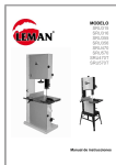
DE
Bedienungsanleitung
Tischkreissäge
EN
Instruction Manual
Table saw
ES
Manual de instrucciones
Sierra de mesa
FR
Mode d´emploi
Scie circulaire à table
PL
Instrukcja obsługi
Tarczowa piła stołowa
CZ
NÁVOD K POUŽITÍ
STOLNÍ PILA
ZI-TKS315
EAN : 912003923836 4
DE
ES
PL
Bedienungsanleitung und Sicherheitshinweise vor Erstinbetriebnahme lesen und
beachten
¡Lea este manual atentamente antes de
usar la máquina!
Przed uruchomieniem maszyny należy
przeczytać instrukcje obsługi oraz zasady
bezpieczeństwa a następnie ich
przestrzegać!
EN
Read the operation manual carefully before
first use.
FR
Lisez attentivement ce manuel avant d'utiliser
la machine!
CZ
Přečtěte si a dodržujte návod k použití a
bezpečnostní pokyny! Technické změny jakož
i chyby tisku a sazby vyhrazeny!
24/10/2012 – Revision 02 - DE/EN/ES/FR/PL/CZ
DE SICHERHEITSZEICHEN
EN
BEDEUTUNG DER SYMBOLE
ES
PL
SEÑALES DE SEGURIDAD
DEFINICIÓN DE SÍMBOLOS
ZNAKI BEZPIECZEŃSTWA
ZNACZENIE SYMBOLI
SAFETY SIGNS
DEFINITION OF SYMBOLS
FR
SIGNALISATION DE SÉCURITÉ
DÉFINITION DES SYMBOLES
CZ
VÝZNAM BEZPEČNOSTNÍCH
SYMBOLŮ
DE
WARNUNG! Beachten Sie die Sicherheitssymbole! Die Nicht-
EN
ATTENTION! Ignoring the safety signs and warnings applied
ES
ATENCIÓN! Ignorar las señales de seguridad y advertencias
FR
ATTENTION! L'ignorance de la signalisation de sécurité et les
PL
UWAGA! Proszę przestrzegać symboli bezpieczeństwa!
CZ
POZOR! Dbejte na bezpečnostní symboly! Nedodržením
DE
ANLEITUNG LESEN! Lesen Sie die Betriebs- und Wartungs-
EN
READ THE MANUAL! Read the user and maintenance manu-
ES
LEA EL MANUAL! Lea el manual de uso y mantenimiento
beachtung der Vorschriften und Hinweise zum Einsatz der Tischkreissäge kann zu schweren Personenschäden und tödliche Gefahren mit sich bringen.
on the table saw as well as ignoring the security and operating
instructions can cause serious injuries and even lead to death.
aplicadas en la máquina, así como ignorar las instrucciones de
seguridad y el manual de instrucciones, pueden causar lesiones
graves e incluso conducir a la muerte.
avertissements sur la machine et les consignes de sécurité et
ignorer les instructions, peut causer des blessures graves et
même entraîner la mort.
Nieprzestrzeganie przepisów i wskazówek odnośnie użytkowania
maszyny może prowadzić do poważnych obrażeń ciała i zagrożeń
życia
bezpečnostních předpisů a pokynů k použití pily může vést k
těžkým zraněním a skončit až smrtí!
anleitung Ihrer Maschine aufmerksam durch und machen Sie sich
mit den Bedienelementen der Maschine gut vertraut um die Maschine ordnungsgemäß zu bedienen und so Schäden an Mensch
und Maschine vorzubeugen.
al carefully and get familiar with the controls n order to use the
machine correctly and to avoid injuries and machine defects,
cuidadosamente y familiarícese con los controles con el fin de
utilizar la máquina correctamente, para evitar lesiones y defectos
de la máquina
2
FR
LIRE LE MANUEL! Lire le manuel d´utilisateur et de mainte-
PL
PRZECZYTAĆ INSTRUKCJĘ! Należy uważnie przeczytać
CZ
PŘEČTĚTE SI NÁVOD! Pozorně si přečtěte návod k použití a
DE
SCHUTZAUSRÜSTUNG! Das Tragen von Gehörschutz,
EN
PROTECTIVE CLOTHING! The operator is obligated to
ES
ROPA DE PROTECCIÓN! El operador está obligado a llevar
FR
VÊTEMENTS DE PROTECTION! L'opérateur est obligé de
PL
WYPOSAŻENIE OCHRONNE! Obowiązkowe jest
CZ
OCHRANNÉ PROSTŘEDKY! Při práci se strojem noste
DE
Dieses Produkt ist CE konform.
EN
This product complies with EC-directives
ES
Este producto cumple con las Directivas CE.
FR
Ce produit est conforme aux Directives CE.
PL
Ten produkt odpowiada wytycznym WE.
CZ
Tento výrobek odpovídá směrnicím EU
nance avec soin et vous familiariser avec les contrôles en vue
d'utiliser la machine correctement et pour éviter les blessures et
les défauts de l'appareil.
instrukcję eksploatacyjną i konserwacyjną Państwa maszyny i
dobrze zapoznać się z elementami obsługi maszyny, ażeby
prawidłowo obsługiwać maszynę i w ten sposób zapobiegać
obrażeniom ciała i uszkodzeniom maszyny.
důkladně se seznamte s ovládáním stroje, abyste předešli škodám
na majetku a možným zraněním
Schutzbrille sowie Sicherheitsschuhen ist Pflicht.
wear proper ear protection, safety goggles and safety shoes.
una protección auditiva adecuada, gafas de seguridad y zapatos
de seguridad.
porter des protecteurs d'oreille, lunettes de sécurité et des chaussures de sécurité.
stosowanie ochrony słuchu, okularów ochronnych, jak również
obuwia roboczego.
vhodné ochranné vybavení (ochrannou obuv, brýle, chrániče
sluchu, …)!
3
Fig. A
Fig. B
2
1
1
6
1
Fig. C
Fig. D
2
10
9
9
5
1
10
4
3
7
8
5
4
Fig. E
Fig. F
9
11
11
8
15
Fig. G
1
Fig. H
15
14
1
13
Fig. I
Fig. J
16
4
5
A
B
5
Fig. K
Fig. L
H
I
G
F
16
17
C
D
E
Fig. M
Fig. N
A
18
19
Fig. O
Fig. P
20
18
20
21
14
6
Fig. Q
Fig. R
23
24
Fig. S
Fig. T
26
24
Spanner
3
Fig. U
wW
28
27
25
Fig. V
X
7
Fig. W
Fig. X
X
X
X
19
X
20
Fig. Y
Fig. Z
X
X
30
Fig. 1
X
33
34
31
Fig. 2
D
32
36
X
35
8
Fig. 3
Fig. 4
37
X
X
38
39
Fig. 5
X
41
42 43
44
40
9
BEDIENUNGSANLEITUNG
DE
Sehr geehrter Kunde!
Wir gratulieren Ihnen zum Erwerb der ZIPPER Tischkreissäge ZI-TKS315. Diese Bedienungsanleitung enthält Informationen und wichtige Hinweise zur Inbetriebnahme und Handhabung des
ZIPPER Tischkreissäge ZI-TKS315. Die Bedienungsanleitung ist Bestandteil der Maschine und darf
nicht entfernt werden. Bewahren Sie sie für spätere Zwecke auf und legen Sie diese Anleitung der
Maschine bei, wenn sie an Dritte weitergegeben wird!
Bitte beachten Sie die Sicherheitshinweise!
Durch die ständige Weiterentwicklung unserer Produkte können Abbildungen und Inhalte geringfügig abweichen. Sollten Sie jedoch Fehler feststellen, informieren Sie uns bitte.
Achtung!
Technische Änderungen vorbehalten!
Urheberrecht
© 2012
Diese Dokumentation ist urheberrechtlich geschützt. Die dadurch verfassungsmäßigen Rechte
bleiben vorbehalten! Insbesondere der Nachdruck, die Übersetzung und die Entnahme von Fotos
und Abbildungen werden gerichtlich verfolgt – Gerichtsstand ist Wels.
Kundendienstadressen
Z.I.P.P.E.R MASCHINEN GmbH
A-4707 Schlüsslberg, Gewerbepark Schlüsslberg 8
Tel 0043 (0) 7248 61116 - 700
Fax 0043 (0) 7248 61116 – 720
[email protected]
10
1
Technische Daten
Motor-Typ
Elektromotor
Betriebsspannung
230 V/50 Hz
Motorleistung
2 kW
Leerlaufdrehzahl
2800 U/Min
Tischgröße
800x550 mm
Tischhöhe
850 mm
Tischverlängerung
800x400 mm
Sägeblatt
Ø315xØ30x3x2 mm
Absaugungsanschluss
Ø100 mm
Max. Schnitthöhe (90°)
83 mm
Max. Schnitthöhe (45°)
60 mm
Schutzklasse
I
Schalldruckpegel
96,2 dB(A)
Schallleistungspegel
103 dB(A)
Abmessungen
900x550x800 mm
Verpackungsmaße
835x600x435 mm
Gewicht (netto/brutto)
49/54 kg
Technische Änderungen vorbehalten.
2
Lieferumfang
1
Stabiler Sägetisch mit Sägeaggregat
2
Untergestell mit Fahrwerk
3
Tischverlängerung
4
Längs- und Gehrungsanschlag
5
Sägeblatt Ø315 mm
6
Bedienungsanleitung
Packen sie die ZIPPER Tischkreissäge ZI-TKS315 aus und überprüfen Sie die Maschine auf einwandfreien Zustand und Vollständigkeit der Lieferung.
11
3
SICHERHEITSHINWEISE
Die ZIPPER Tischkreissäge ZI-TKS315 darf ausschließlich zum Schneiden von Holzwerkstoffen
betrieben werden. Eigenmächtige Veränderungen und Manipulationen an der Maschine führen
zum sofortigen Erlöschen sämtlicher Gewährleistungs- und Schadenersatzansprüche.
Betrieb der Maschine nur bei ausreichenden Lichtverhältnissen, nach Einbruch der Dämmerung sollten Sie nicht mehr arbeiten.
Bei Müdigkeit, Unkonzentriertheit bzw. unter Einfluss von Medikamenten,
Alkohol oder Drogen ist das Arbeiten mit der Maschine verboten!
Arbeiten Sie konzentriert, sicherheitsbewusst und achten Sie stets auf einen
sicheren STAND beim Arbeiten!
Arbeiten Sie stets mit der Hilfe des Anschlages und des Schiebestockes!
Die Maschine ist nicht für das Arbeiten im Freien bzw. in einer feuchten Umgebung bestimmt!
Rutschen/ Stolpern/Fallen ist eine Hauptursache für schwere oder tödliche
Verletzungen. Passen Sie auf unebene oder rutschige Arbeitsflächen auf.
Die Maschine darf nur vom eingeschulten Fachpersonal bedient werden.
Unbefugte, insbesondere Kinder, und nicht eingeschulte Personen sind von
der Arbeitsumgebung fern zu halten!
Wenn Sie mit der Maschine arbeiten, tragen Sie keinen lockeren
Schmuck, weite oder vom Körper abstehende Kleidung, Krawatten,
langes, offenes Haar, etc …
Lose Objekte können sich in rotierenden Teilen der Maschine verfangen und zu Verletzungen führen!
Geeignete Schutzausrüstung (SICHERHEITSSCHUHE MIT STAHLKAPPEN,
Schutzbrille, Gehörschutz, …) tragen!
Führen Sie sämtliche Wartungs- und Umrüstarbeiten nur nach vorheriger
Trennung vom elektrischen Netz durch!
i. Restrisiken
Auch bei Einhaltung aller Sicherheitsbestimmungen und bei bestimmungsgemäßer Verwendung sind folgende Restrisiken zu beachten:
Verletzungsgefahr für die Hände/Finger durch das rotierende Kreissägeblatt während dem
Betrieb.
Verletzungsgefahr durch Kontakt mit spannungsführenden Bauteilen.
Verletzungsgefahr durch Bruch bzw. Herausschleudern des Kreissägeblattes bzw. Kreissägeblattteile, vor allem bei Überlastung.
12
Gehörschäden, sofern keine Vorkehrungen seitens des Benutzers für Gehörschutz getroffen wurden.
Verletzungsgefahr durch Rückschlag des Schnittgutes, Herausschleudern des Schnittgutes
bzw. Teile davon.
Verletzungsgefahr für das Auge durch herumfliegende Teile, auch mit Schutzbrille.
Gefahr durch Einatmen von giftigem Holzstaub bei behandelten Werkstücken.
Diese Risiken können minimiert werden, wenn alle Sicherheitsbestimmungen angewendet
werden, die Maschine ordentlich gewartet und gepflegt wird und die Maschine bestimmungsgemäß und von entsprechend geschultem Fachpersonal bedient wird.
4
Montage
Fig. A
o Platzieren Sie die Füße 2, wie in der Skizze gezeigt, auf dem Maschinenhauptkörper 1. Benützen Sie dazu pro Fuß 2 Sechskantschrauben M6x16, 2 Beilagscheiben 6 und 2 Muttern
M6. Ziehen Sie die Schrauben aber nicht zu fest an, damit diese nicht ausreißen können!
Fig. B
o Montieren Sie anschließend die Schalter 6 auf dem Maschinengestell 1 mithilfe von 2 Muttern M4 und den dazugehörigen Beilagscheiben.
Fig. C
o Befestigen Sie den letzten Fuß 5, den Verlängerungstisch 8 und die Schlauchklemme 7 mit
4 Muttern M6 und 4 Beilagscheiben 6 auf dem Maschinenkörper 1. Diese Position ist über
den Verlängerungstisch in Fig. U ersichtlich.
Fig. D
o Benützen Sie 12 Sechskantschrauben M6x16 und die dazugehörigen Muttern und
Beilagscheiben um die Füße 2, 3, 4, 5 laut Skizze mit den Querleisten 9,10 zu verbinden.
Achten Sie wieder darauf, dass Sie die Schrauben nicht zu fest anziehen.
Fig. E
o Montieren Sie die Stütze für den Verlängerungstisch 11 mit 4 Sechskantschrauben M6x16
und den dazugehörigen Beilagscheiben und Muttern auf dem Verlängerungstisch und der
Querleiste 9.
Fig. F
o Montieren Sie die Führung für den Anschlag 15 an der Vorderseite der Maschine 1. Verwenden Sie dazu 2 Schrauben M6x30.
Fig. G
o Die zweite Führung ist an der linken Seite der Maschine anzubringen.
Der Anschlag kann so später zwischen diesen Führungen gewechselt werden (Längs- bzw.
Queranschlag)
Fig. H
o Befestigen Sie den Absaugungsanschluss 14 mithilfe von 4 Sechskantschrauben M4x10 an
der dafür vorgesehenen Halterung 13.
Fig. I
o Durch 4 Sechskantschrauben M6x16 werden anschließend die Räder an den beiden Füßen
4, 5 befestigt.
Fig. J
o Ziehen Sie die Schrauben an den Positionen A und B nach.
Fig. K
o Ziehen Sie die Schrauben an den Stellen A bis G nach. Lassen Sie Position H noch locker.
13
Fig. L
o Drehen Sie nun die Maschine um, sodass Sie auf den Füßen steht. Stellen Sie nun den Teil
17 auf dem Teil 16 so ein, dass die Rolle den Boden berührt. Ziehen Sie nun auch die
Schraube an dieser Position nach.
Fig. M
o Lösen Sie die Schraube A und montieren Sie den Spaltkeil 18. Stellen Sie diesen so ein,
dass der erforderliche Abstand laut Skizze erreicht wird. Ziehen Sie anschließend die
Schraube wieder an.
Fig. N
o Bewegen Sie das Sägeblatt an die unterste Position und fügen Sie den Teil 19 ein. Befestigen Sie diesen mit 4 Kreuzsenkschrauben M6x16.
Fig. O
o Benützen Sie eine Rundkopfschraube M6x25 und die zugehörige Mutter um die Schutzhaube auf dem Spaltkeil zu montieren.
Fig. P
o Verbinden Sie den Absaugungsanschluss der Schutzhaube 20 und den Absaugungsanschluss 14 mit dem Verbindungsschlauch 21. Stecken Sie den Schlauch anschließend in
die Schlauchklemme 7.
Fig. Q
o Benützen Sie nun 2 Schrauben M6x20 um den Anschlag 23 mit dem Teil 24 zu verbinden.
Fig. R
o Drücken Sie den Montageteil in die Kante der Führung.
Fig. S
o Verwenden Sie 2 M6 Schrauben um den Teil 25 auf dem Fuß 3 zu fixieren.
Fig. T
o Montieren Sie nun mit 4 Sechskantschrauben M6x16 und den zugehörigen Muttern und
Beilagscheiben die einzelnen Teile des Griffes 26, 27, 28 auf die Füße 2 und 3.
Fig. U
o Kontrollieren Sie, ob die Maschine nun so aussieht, wie auf der Skizze.
5
Betriebshinweise
i. Platzieren der Maschine (Fig. V)
Verwenden Sie zum Wechseln des Standortes die Transporträder. Durch die Griffe ist die Maschine so relativ einfach zu transportieren. Achten Sie bei der Wahl des Arbeitsplatzes darauf,
dass der Boden eben ist.
ii. Starten/Stoppen (Fig. 1)
Durch Drücken des Schalters 34 wird die Maschine eingeschaltet. Ausgeschaltet wird sie durch
den Schalter 33.
iii. Einstellen der Schnitttiefe (Fig. 2)
Stellen Sie die Schnitttiefe immer so ein, dass das Sägeblatt etwa 2-3 Zentimeter über das
Werkstück ragt. Einstellen lässt sie sich durch das Handrad 35. Die Höhe des Blattes lässt sich
auf der Skala 36 ablesen.
14
iv. Einstellen der Sägeblattneigung (Fig. 3 und 4)
Für schräge Schnitte muss zuerst die Klemmschraube 39 geöffnet werden. Danach wird die
zweite Klemmschraube 38 gelöst. Danach lässt sich die Blattneigung, die auf der Skala 37 abzulesen ist, einstellen. Dann müssen die beiden Klemmschrauben wieder geschlossen werden.
v. Einstellen des Gehrungsanschlags (Fig. 5)
Schrägeneinstellung: Öffnen Sie zuerst die Klemmschraube 40. Die Schräge lässt sich auf der
Skala 41 ablesen. Für die wichtigsten Schrägen sind Kerben 42 vorgesehen. Durch die Raste
43 lassen sich diese Schrägen einfach einstellen. Nach der Einstellung muss die Klemmschraube wieder festgezogen werden.
Einstellung des Abstandes zum Sägeblatt: Bewegen Sie den Anschlag auf das gewünschte Maß,
das auf der Skala 44 abzulesen ist.
6
Wartung und Pflege
ACHTUNG
Keine Reinigung, Instandhaltung, Prüfung bei eingeschalteter Maschine!
Daher gilt: Vor Wartungsarbeiten Maschine ausschalten, und von der Netzspannung trennen!
Die Maschine ist wartungsarm und enthält nur wenig Teile, die der Bediener einer Instandhaltung
unterziehen muss. Störungen oder Defekte, die die Sicherheit der Maschine beeinträchtigen können, umgehend beseitigen lassen. Reparaturtätigkeiten dürfen nur von Fachpersonal durchgeführt
werden!
i. Wechseln des Sägeblattes (Fig. W, X, Y, Z)
Lösen Sie die Schraube und demontieren Sie die Schutzhaube 20.
Nehmen Sie anschließend den Teil 19 von der Maschine.
Benützen Sie das spezielle Werkzeug, das mit der Maschine geliefert wurde, um die Mutter
31 zu lösen, die das Sägeblatt 32 fixiert.
Nehmen Sie nun das Sägeblatt heraus und fügen Sie das neue ein.
Gehen Sie für den Einbau sinngemäß in der umgekehrten Reihenfolge vor.
ii. Instandhaltung- und Wartungsplan
Kontrollen zur Instandhaltung der Maschine
Lockere oder verlorene Schrauben
Täglich vor Inbetriebnahme
Beschädigung irgendwelchen Teiles
Täglich vor Inbetriebnahme
Maschine säubern
Täglich nach Inbetriebnahme
iii. Reinigung
Gesamte Maschine von Spänen, Staub und anderen Verschmutzungen befreien. Maschinengehäuse mit einem feuchten Tuch und gegebenenfalls etwas handelsüblichem Spülmittel säubern.
15
HINWEIS
Der Einsatz von Lösungsmitteln, aggressiven Chemikalien oder Scheuermitteln führt zu Sachschäden an der Maschine!
Daher gilt: Bei der Reinigung nur Wasser und ggf. milde Reinigungsmittel
verwenden!
6.1
Entsorgung
Entsorgen Sie Ihre ZI-TKS315 nicht im Restmüll. Kontaktieren Sie Ihre lokalen Behörden für Informationen bzgl. der verfügbaren Entsorgungsmöglichkeiten. Wenn Sie bei Ihrem Fachhändler eine neue Tischkreissäge oder ein
gleichwertiges Gerät kaufen, ist dieser verpflichtet, Ihren alten fachgerecht
zu entsorgen.
6.2
Lagerung
Die Tischkreissäge gut bedecken und an einem trockenen und sauberen Ort lagern.
7
Ersatzteilbestellung
Mit Originalteilen von Zipper verwenden Sie Ersatzteile, die ideal aufeinander abgestimmt sind.
Die optimale Passgenauigkeit der Teile verkürzen die Einbauzeiten und erhalten die Lebensdauer.
HINWEIS
Der Einbau von anderen als Originalersatzteilen führt zum Verlust der Garantie!
Daher gilt: Beim Tausch von Komponenten/Teilen nur Originalersatzteile verwenden
Fordern Sie bei Bedarf die Ersatzteilliste und –zeichnung vom ZIPPER Kundendienst an.
Bestelladresse sehen Sie unter Kundendienstadressen im Vorwort dieser Dokumentation.
16
USER MANUAL
EN
Dear Customer!
This manual contains important information and advice for the correct and safe use and maintenance of the ZIPPER Table saw ZI-TKS315. The manual is part of the machine and may not be
stored separately. Read it profoundly before first use of the machine and keep it for later reference. When the machine is handed to other persons always put the manual to the machine.
Please follow the security instructions!
Due to continuous development of our products illustrations, pictures might differ slightly.
Attention!
Technical changes reserved!
Copyright
© 2012
This manual is protected by copyright law – all rights reserved. Especially the reprinting as well as
the translation and depiction of pictures will be prosecuted by law. Court of jurisdiction is WELS,
Austria.
Customer Support
Z.I.P.P.E.R MASCHINEN GmbH
A-4707 Schlüsslberg, Gewerbepark Schlüsslberg 8
Tel 0043 (0) 7248 61116 - 700
Fax 0043 (0) 7248 61116 – 720
[email protected]
17
1
Technical details
Type of the engine
Electrical engine
Voltage
230 V/50 Hz
Engine power
2 kW
Engine speed
2800 U/Min
Table size
800x550 mm
Table height
850 mm
Table extension
800x400 mm
Saw blade
Ø315xØ30x3x2 mm
Dust collector plug
Ø100 mm
Max. cutting height (90°)
83 mm
Max. cutting height (45°)
60 mm
Protection class
I
Sound pressure level
96,2 dB(A)
Sound power level
103 dB(A)
Dimensions
900x550x800 mm
Packing size
835x600x435 mm
Weight (net/gross)
49/54 kg
Technical changes reserved.
2
Included in Delivery
1
Stable saw table with engine
2
Stand and chassis
3
Table extension
4
Longitudinal and mitre fence
5
Saw blade Ø315 mm
6
User manual
Unpack the ZIPPER table saw ZI-TKS315 and check the machine for any transport damage and
for completeness of delivery.
18
3
SAFETY INSTRUCTIONS
The ZIPPER table saw ZI-TKS315 shall be used only for cutting of wood.
ZIPPER MASCHINEN cannot be held responsible for any injuries or damages if there was performed manipulation or adjustments to the machine.
Do not operate the machine at insufficient lighting conditions.
Do not operate the machine indoors.
Do not operate the machine when you are tired, when your concentration is
impaired, and/ or under the influence of drugs, medication or alcohol.
Always be focused when working, take care to maintain a safe posture at
every time.
Always use the fence and the sliding stick!
Don’t use the machine outdoors or in a wet area!
Slipping/ stumbling/ falling down are a frequent cause of severe injuries.
The machine shall be used only by trained persons.
Non authorized persons, especially children, shall be kept away from the
working area.
Do not wear loose clothing, long hair openly or loose jeweler like
necklaces etc. when operating the machine
They might be catched by rotating parts and cause serious injuries.
Use proper safety clothing and devices when operating the machine (safety
gloves, safety goggles, ear protectors, safety shoes …)!
Before doing some works of maintenance, you have to disconnect the machine from the electrical net!
3.1
Remaining risks
Even if you abide by all the safety regulations you’ll have to attend following remaining risks:
Danger of injury for the hands/fingers from the rotating saw blade during the operation.
Danger of injury at contact with voltage-carrying parts.
Danger of injury through break or spinning out of the saw blade or parts of it.
Hearing damage, when the operator didn’t protect his ears.
Danger of injury through setback or spinning out of the work piece or parts of it.
19
Danger of injury for the eyes through flying parts, even with protecting glasses.
Danger through breathing of poisonous dust (treated wood)
These risks can be minimized, if all the safety regulations are applied, the machine is maintained regularly and the machine is operated from trained expert staff.
4
Assembly
Fig. A
o Put the feet 2 as shown in the picture on the main part 1. For this you have to use for
every foot 2 six-head screws M6x16, nuts and flat washers. Don’t tighten the screws too
firmly!
Fig. B
o Then mount the switch 6 on the main part 1 with 2 nuts M4 and flat washers.
Fig. C
o Fix the last foot 5, the extension table 8 and the hose clip 7 with 4 nuts M6 and 4 flat
washers on the main part 1. You can see this position in Fig. U.
Fig. D
o Use 12 six-head screws M6x16 and the related nuts and flat washers to connect the feet
2, 3, 4, 5 with the transverse strip 9, 10.
Fig. E
o Mount the column fort he extension table 11 on the extension table and the transverse
strip 9 by using 4 six-head screws M6x16 and the related nuts and flash washers.
Fig. F
o Assemble the guideline for the fence 15 on the front side of the machine 1. Use 2 screws
M6x30.
Fig. G
o The second guideline has to be mounted on the left side of the machine.
So the fence can be changed between these two guidelines later.
Fig. H
o Fix the dust collector plug 14 with 4 six-head screws M4x10 on the holder 13.
Fig. I
o Using 4 six-head screws M6x16, you have to fix the two wheels on the feet 4, 5.
Fig. J
o Drag the screws at the positions A and B behind.
Fig. K
o Drag the screws at the places A to G behind. Let the screws at position H loose.
Fig. L
o Now turn the table round, so that it stands on its feet. Then adjust part 17 on part 16 so
that the wheel touches the floor. Now drag the screws at this place behind.
Fig. M
o Loose the screw A and mount the riving knife 18. You have to adjust it so that the distance, shown in the picture, is reached. Now fasten the screw again.
Fig. N
o Move the saw blade to the lowest position. Insert part 19 and fix it with 4 cross countersunk screws M6x16.
Fig. O
o Use a screw M6x25 and the related nut to mount the protective cap on the riving knife.
20
Fig. P
o Connect the dust collector plug of the protective cap 20 and the dust collector plug 14
with the hose 21. Then stick the hose into the hose clip.
Fig. Q
o Now use 2 screws M6x20 to connect the fence 23 with the part 24.
Fig. R
o Push the assemble part into the chamfer of the guide.
Fig. S
o Using 2 screws M6, fix the part 25 on the foot 3.
Fig. T
o Now mount the parts of the handle 26, 27, 28 on the feet 2 and 3 by using 4 six-head
screws M6x16 and the related nuts and flat washers.
Fig. U
o Now control whether the machine looks like the machine on the picture.
5
Operation instructions
Placement of the machine (Fig. V)
For changing the place you have to use the wheels. By lifting the machine at the handles, the
machine is very easy moved. Regard that the floor is planar.
Starting/Stopping (Fig. 1)
Pushing the switch 34, the machine is turned on. It gets turned off by using switch 33.
Adjustment of the blade depth (Fig. 2)
Always adjust the blade depth so, that the top of the saw blade is about 2-3 cm over the work
piece. It is adjusted by the hand wheel 35. You can read the height of the saw blade on the
scale 36.
Adjustment of the blade tilt (Fig. 3 und 4)
For tilted cuts you have to open the lock screw 39. Then you have to open the second lock
screw 38. The tilt can now be adjusted and read on the scale 37. Then the two lock screws
have to be fixed again.
Adjustment of the fence (Fig. 5)
Angular adjustment: At first you have to open the lock screw 40. The angle can be read on the
scale 41. For the most important angles there are grooves. Using the detent 43 these angles
can be adjusted easily. After the adjusting the lock screw must be fixed again.
Adjustment of the distance to the saw blade: Move the fence to the wished measure which can
be read on the scale 44.
21
6
Maintenance
ATTENTION – DANGER!
No cleaning, upkeep, checks or maintenance when machine is running
Be safe: Shut off the machine, let it cool down, disconnect the machine from the power
supply.
The machine does not require intense maintenance. However, to ensure a long lifespan, we
strongly recommend following the upkeep and maintenance plan.
Repairs must be carried out by specialists! Use original ZIPPER parts only!
Changing of the saw blade (Fig. W, X, Y, Z)
Loose the screw and dismount the part 20.
Then take part 19 off the machine.
Now loose the nut 31, fixing the saw blade 32, with the special tool delivered with the
machine.
Change the saw blades.
For the Assembly you have to do these steps backwards.
Upkeep and maintenance plan
Loose or lost screws, nuts, bolts
Regularly prior to each operation
Damage of any part of the machine
Regularly prior to each operation
Machine cleaning
Regularly after operation
Cleaning
Clean the machine from dirt, chippings, etc … Clean the machine housing with a wet cloth and
a mild cleaning solution.
IMPORTANT
The usage of solvents, aggressive chemicals or scouring agents damages
the machine housing.
Disposal
DO NOT dispose your ZI-TKS315 in the residual waste! Contact your local authorities for information about best available disposal possibilities in your area.
Drain fuel from the fuel tank completely before disposing the earth auger. Disaggregate the auger into its components before disposing its compo.
Storage
Cover the machine with a cloth sheet and store it at a dry place.
22
7
Spare part order
With original ZIPPER spare parts you use parts that are attuned to each other and shorten the
installation time and elongate your machines lifespan.
HINWEIS
The installation of non-original parts renders warranty null and void.
Exempted is the replacement of the spark plug if carried out by a specialist.
Send your spare part list inquiry to the reseller you acquired the machine from or to the
ZIPPER Customer Service.
You find the order address in the preface of this operation manual.
23
MANUAL DE INSTRUCCIONES
ES
¡Estimado Cliente!
Este manual contiene información y consejos para el uso correcto y seguro y el mantenimiento de
la sierra de mesa ZI-TKS315 de ZIPPER. El manual forma parte de la máquina y no podrá ser
guardado por separado. Lea con cuidado antes del primer uso de la máquina y guárdelo para
futuras consultas. Cuando la máquina se entrega a otras personas, adjunte siempre el manual a
la máquina.
¡Por favor, siga las instrucciones de seguridad!
Debido al desarrollo continuo de nuestros productos, las ilustraciones, las imágenes pueden variar
ligeramente.
¡Atención!
Se admiten cambios técnicos.
Copyright
© 2012
Este documento está protegido por la ley internacional de derechos de autor. Todos los derechos
reservados. Especialmente la reimpresión, así como la traducción y la representación de
imágenes será perseguida por la ley. Competencia del Tribunal de Wels, Austria.
Atención al Cliente
Z.I.P.P.E.R MASCHINEN GmbH
Gewerbepark 8
A-4707 Schlüßlberg
Tel 0043 (0) 7248 61116 - 700
Fax 0043 (0) 7248 61116 – 720
[email protected]
24
1
Datos técnicos
Tipo de motor
Motor eléctrico
Voltaje
230 V/50 Hz
Potencia del motor
2 kW
Velocidad del motor
2800 U/Min
Medidas de la mesa
800x550 mm
Altura de la mesa
850 mm
Extensión de la mesa
800x400 mm
Disco de sierra
Ø315xØ30x3x2 mm
Boca de aspiración
Ø100 mm
Altura máxima de corte (90°)
83 mm
Altura máxima de corte(45°)
60 mm
Clase de protección
I
Nivel de presión sonora
96,2 dB(A)
Nivel de potencia acústica
103 dB(A)
Dimensiones
900x550x800 mm
Medidas de embalaje
835x600x435 mm
Peso (neto/bruto)
49/54 kg
Se admiten cambios técnicos.
2
Entrega de la mercancía
1
Mesa de sierra estable con motor
2
Estand y chasis
3
Mesa de extensión
4
Palograma y guía transversal
5
Disco de sierra Ø315 mm
6
Manual de isntrucciones
Desembale la sierra de mesa ZIPPER ZI-TKS315 y compruebe que la máquina no tiene daños de
transporte y que la totalidad de la máquina se le ha entregado.
25
3
INSTRUCCIONES DE SEGURIDAD
La sierra de mesa ZI-TKS315 sólo se debe utilizar para el corte de madera.
ZIPPER MASCHINEN no se hace responsable de los daños y perjuicios, si la máquina ha sido
manipulada o se han hecho ajustes a la máquina.
No trabaje con la máquina en condiciones de iluminación insuficiente.
No use la máquina en interiores.
No trabaje con la máquina cuando esté cansado, desconcentrado y/o bajo la
influencia de drogas, medicamentos o alcohol.
Siempre esté centrado cuando trabaje, tenga cuidado de mantener una
postura segura en cada momento.
¡Use siempre la guía y el empujador!
No trabaje con la máquina en lugares húmedos.
Resbalarse/tropezarse/caerse son una causa frecuente de lesiones graves..
La máquina debe ser utilizada tan sólo por personas capacitadas.
Las personas no autorizadas, especialmente los niños, deberán estar
alejadas de la zona de trabajo.
Cuando trabaje con la máquina no lleve ropa suelta, el pelo largo
suelto o joyas, tales como collares etc.
Los objetos sueltos pueden engancharse a las partes móviles de la
máquina y causar serios daños.
Use ropa y equipos de seguridad apropiadas cuando trabaje con la máquina
(gafas de seguridad, zapatos de seguridad…).
¡Antes de cualquier operación de mantenimiento desconecte la máquina de
la fuente de energía!
26
3.1
Riesgos residuales
Incluso si usted atiende a todas las instrucciones de seguridad, aún existen algunos riesgos
residuales:
Riesgo de lesiones en las manos/dedos por el disco durante la operación de rotación.
Peligro de lesiones por el contacto con los elementos portadores de tensión.
Riesgo de lesión por la rotura y giro fuera de la sierra de partes de la pieza, sobre todo en
caso de sobrecarga.
Daños auditivos, cuando el usuario no utiliza ningún tipo de protección.
¡Peligro de lesiones por contragolpe de la pieza, girando fuera de la pieza de trabajo o
partes de la misma.
Riesgo de lesión en el ojo por partes de la pieza que salen disparadas, incluso con gafas
de seguridad.
Peligro por la inhalación de polvo tóxico de los materiales tratados.
Estos riesgos pueden ser minimizados cuando todas las instrucciones de seguridad se aplican,
y el mantenimiento de la máquina se realiza cuidadosamente y la máquina es operada por el
personal capacitado.
4
Montaje
Fig. A
o Ponga las 2 patas como se muestra en la imagen de la parte principal 1. Para ello, tiene
que utilizar en cada pata 2 tornillos de cabeza hexagonal M6x16, tuercas y arandelas planas. No apriete los tornillos demasiado!
Fig. B
o A continuación, monte el interruptor 6 en la parte principal 1 con 2 tuercas M4 y arandelas
planas.
Fig. C
o Fijar el último pie 5, la mesa de extensión 8 y la abrazadera de la manguera 7 con 4 tuercas M6 y 4 arandelas planas en la parte principal 1. Puede ver esta posición en la figura.
U.
Fig. D
o Utilice 12 tornillos hexagonales M6x16 y las tuercas y arandelas planas relacionadas para
conectar las patas 2, 3, 4, 5 con la franja transversal 9, 10.
Fig. E
o Monte la columna de la mesa de extensión 11 en la mesa de extensión y la franja transversal 9 con 4 tornillos hexagonales M6x16 y las tuercas y arandelas planas relacionadas.
Fig. F
o Monte la guía para el palograma 15 en la parte frontal de la máquina 1. Utilice 2 tornillos
M6x30.
Fig. G
o La segunda guía tiene que ser montada en el lado izquierdo de la máquina.
Así el palograma se puede cambiar entre estas dos guías más tarde.
Fig. H
o Fije la toma del aspirador 14 con 4 tornillos hexagonales M4x10 en el soporte 13.
Fig. I
o Mediante 4 tornillos hexagonales M6x16, fije las dos ruedas en las patas 4, 5.
Fig. J
o Meta los tornillos en las posiciones A y B detrás.
Fig. K
27
o Ponga los tornillos en los puntos, de A a G detrás. Deje los tornillos en la posición H sueltos.
Fig. L
o Gire la mesa, de modo que quede en pie. A continuación, ajuste la parte 17 en la parte 16
para que la rueda toque el suelo. Ahora ponga los tornillos de detrás.
Fig. M
o Afloje el tornillo A y monte la cuña separadora 18. Ajústela de forma que la distancia sea
la que se muestra en la imagen. Ahora apriete el tornillo de nuevo.
Fig. N
o Mueva el disco de sierra a la posición más baja. Introduzca la pieza 19 y fíjela con 4 tornillos avellanados M6x16.
Fig. O
o Use un tornillo M6x25 y la tuerca de montaje relacionada para montar la tapa protectora
en la cuña separadora.
Fig. P
o Conecte la toma de aspiración de la tapa de protección 20 y el enchufe del aspirador 14
con la manguera 21. A continuación, introduzca la manguera en la abrazadera de la manguera.
Fig. Q
o Ahora use dos tornillos M6x20 para conectar el palograma 23 con la parte 24.
Fig. R
o Empuje la parte montada en el borde de la guía.
Fig. S
o Use 2 tornillos M6 para fijar la parte 25 en la pata 3.
Fig. T
o Monte las piezas de la manija 26, 27, 28 en las patas 2 y 3 por medio de 4 tornillos hexagonales M6x16 y las tuercas y arandelas planas relacionadas.
Fig. U
o Ahora mire si la máquina se parece a la máquina en la imagen.
5
Instrucciones de uso
Colocación de la máquina (Fig. V)
Para mover la máquina de un lugar a otro, utilice las ruedas. Al levantar la máquina con las
manijas, la máquina se mueve fácilmente. Tenga cuidado que el suelo esté plano.
Encendido/Apagado (Fig. 1)
Al pulsar el interruptor 34, la máquina se enciende. Se apaga pulsando el interruptor 33.
Ajuste de la profundidad del disco (Fig. 2)
Ajuste siempre la profundidad del disco de manera que la parte superior del disco de sierra
esté aproximadamente 2-3 cm por encima de la pieza de trabajo. Se ajusta con el volante 35.
Puede leer la altura del disco de sierra en la escala de 36.
Ajuste de la inclinación del disco (Fig. 3 y 4)
Para cortes inclinados tiene que abrir el tornillo de bloqueo 39. Después tiene que abrir el segundo tornillo de bloqueo 38. La inclinación se puede ajustar y leer en la escala 37. Los dos
tornillos de seguridad deben ser fijados de nuevo.
28
Ajuste del palograma (Fig. 5)
Ajuste del ángulo: Primero tiene que abrir el tornillo de bloqueo 40. El ángulo se puede leer en
la escala 41. Para los ángulos más frecuentes hay ranuras. Usando el retén 43 estos ángulos
se pueden ajustar fácilmente. Después del ajuste, el tornillo de bloqueo debe fijarse de nuevo.
Ajuste de la distancia al disco de sierra: Mueva el palograma a la medida deseada que se puede leer en la escala 44.
6
Mantenimiento
¡ATENCIÓN! - PELIGRO
No haga la limpieza, control, ajustes o mantenimiento cuando la máquina
esté funcionando.
Asegúrese: Apague la máquina, deje que se enfríe y desconéctela
completamente.
La máquina no requiere mantenimiento intenso. Sin embargo, para garantizar una larga vida útil,
le recomendamos seguir el plan de mantenimiento.
Las reparaciones deben ser llevadas a cabo por los especialistas. Utilice repuestos originales de
ZIPPER!
Cambio del disco de sierra (Fig. W, X, Y, Z)
Afloje el tornillo y desmonte la parte 20.
Retire la parte 19 de la máquina.
Ahora suelte la tuerca 31 que fija el disco de sierra 32, con la herramienta especial suministrada con la máquina
Cambie el disco de sierra.
Para el montaje tiene que hacer estos pasos al revés.
Plan de mantenimiento
Tornillos sueltos, perdidos, tuercas,
pernos
Antes de cada uso
Daños en la máquina
Antes de cada uso
Limpieza de la máquina
Después de cada uso
Limpieza
Limpie la máquina de las astillas, del polvo, etc. Limpie la carcasa de la máquina con un paño
húmedo y una solución limpiadora suave.
29
IMPORTANTE
El uso de disolventes, productos químicos agresivos o productos
de limpieza abrasivos pueden dañar la carcasa de la máquina.
6.1
Eliminación de desechos
¡NO se deshaga de su ZI-TKS315 en los residuos no reciclables! Póngase en
contacto con las autoridades locales para obtener información sobre las
mejores posibilidades de reciclado en su área. Desmonte la máquina en sus
componentes antes de reciclar sus componentes.
6.2
Almacenamiento
Guarde siempre la máquina en un lugar limpio, seco y cúbrala con una
tela.
7
Pedido de recambios
Con las piezas de recambio originales de ZIPPER utilizará piezas que están en sintonía con las
demás piezas, acortando el tiempo de instalación y alargando la vida útil de la máquina.
IMPORTANTE
La instalación de piezas no originales, hace nula la garantía. ¡Use sólo
repuestos originales!
Envíe su pregunta sobre las piezas que necesite al revendedor donde
compró la máquina o al Atención al Cliente de ZIPPER.
Puede encontrar la dirección de pedidos en el prefacio de este manual de instrucciones.
30
MODE D´EMPLOI
FR
Cher Client!
Ce manuel contient des informations et des conseils pour une utilisation correcte et sûre et l'entretien du scie circualire á table ZIPPER ZI-TKS315. Le manuel fait partie de la machine et ne
peuvent pas être stockés séparément. Lire attentivement avant la première utilisation de la machine et le conserver pour référence future. Lorsque la machine est à d'autres personnes, toujours mettre le manuel à la machine.
S'il vous plaît suivez les consignes de sécurité!
Le développement continu de nos produits, les illustrations, les images peuvent varier légèrement.
Attention!
Sous réserve de modifications techniques.
Droit d'auteur
© 2012
Ce document est protégé par le droit international des droits d'auteur. Tous droits réservés. Surtout la réimpression et la traduction et la représentation des images seront poursuivies par la loi.
Compétence de la Cour de Wels, en Autriche.
Contact service après vente
Z.I.P.P.E.R MASCHINEN GmbH
Gewerbepark 8
A-4707 Schlüßlberg
Tel 0043 (0) 7248 61116 - 700
Fax 0043 (0) 7248 61116 – 720
[email protected]
31
1 Détails techniques
Type de moteur
Moteur électrique
Tension
230 V/50 Hz
Puissance du moteur
2 kW
Vitesse du moteur
2800 tr/Min
Mesures de la table
800x550 mm
Hauteur de la table
850 mm
Rallonge de table
800x400 mm
Lame de scie
Ø315xØ30x3x2 mm
Bouche de aspiration
Ø100 mm
Hauteur maximale de coupe
(90°)
Hauteur maximale de coupe
(45°)
83 mm
60 mm
Classe de protection
I
SPL
96,2 dB(A)
Niveau de puissance acoustique
103 dB(A)
Dimensions
900x550x800 mm
Mesures d'emballage
835x600x435 mm
Poids (net/brut)
49/54 kg
Sous réserve de modifications techniques.
2 Livraison de la machine
Décompressez le ZIPPER ZI-TKS315 et vérifier que la machine n'a pas de dommages dus au
transport et que toute la machine a été livrée.
1
Table de scie stable avec motor
2
Stand et châssis
3
Table d´extension
4
Guide paralléle et transversal
5
Lame de scie Ø315 mm
6
Mode d´emploi
32
3
CONSIGNES DE SÉCURITÉ
La scie circulaire à table ZI-TKS315 doit être utilisé uniquement pour couper le bois.
ZIPPER MASCHINEN n´est pas responsable des dommages si la machine a été altéré ou ont procédé à des ajustements à la machine.
Ne pas faire fonctionner la machine en conditions de faible luminosité.
Ne pas utiliser la machine à l'intérieur.
Ne pas faire fonctionner la machine lorsque vous êtes fatigué, quand vous
êtes décentralisée et / ou sous l'influence de drogues ou d'alcool.
Toujours rester concentré au travail, veiller à maintenir une position sûre en
tout temps.
Ne travaillez pas sur un terrain glissant.
Le fonctionnement de la machine sur de la glace ou le sol couvert de neige
est interdite!
Glissant / déclenchement / à la baisse est une cause fréquente de blessures
graves.
La machine devrait être utilisée que par des personnes formées.
Les personnes non autorisées, en particulier les enfants, devraient être retirés de la zone de travail.
Lorsque vous travaillez avec la machine ne porte pas de vêtements
amples, cheveux longs ou des bijoux tels que colliers, etc.
Les éléments individuels peuvent être couplés à des pièces mobiles
de la machine et provoquer de graves dommages.
Porter un équipement de sécurité approprié lorsque vous travaillez avec des
machines (des lunettes de sécurité, chaussures de sécurité ...).
Avant tout entretien débrancher la machine de la source d'alimentation!
33
3.1
Risques résiduels
Même si vous répondez à toutes les normes de sécurité doivent être conscients des risques résiduels:
Risque de blessures aux mains / doigts dans la lame de scie au cours de l'opération de rotation.
Risque de blessures par contact avec des pièces sous tension.
Risque de blessure par essaimage de la rupture et a vu les parties de la pièce, en particulier
en cas de surcharge
Les dommages auditifs lorsque l'utilisateur n'utilise pas de protection.
Risque de blessure en cas de rebond de la pièce en fermant la pièce ou de parties de celuici.
Risque de blessures à l'œil dans certaines parties de la pièce à tourner, même avec des lunettes de sécurité.
Risque d'inhalation de poussières toxiques des matériaux traités.
Ces risques peuvent être minimisés si les consignes de sécurité applicables, et l'entretien de la
machine est fait avec soin.
4 Assemblage
Fig. A
o Mettez les deux pieds comme indiqué dans l'image de la partie principale 1. Pour ce faire,
vous devez utiliser sur chaque pied de deux vis à tête hexagonale M6x16, écrous et rondelles. Ne pas serrer les vis!
Fig. B
o Puis montez l'interrupteur 6 dans la partie principale 1 avec deux écrous et rondelles M4.
Fig. C
o Fixer le dernière pied 5, le rallonge de table 8 et le collier de serrage 7 avec quatre vis M6
et 4 écrous rondelles sur le principal. Vous pouvez voir cette position de la figure U.
Fig. D
o Utilisez 12 boulons M6x16 et des écrous et des rondelles pour connecter les pieds 2, 3, 4,
5 avec la bande transversale 9, 10.
Fig. E
o Monter la colonne de la table extension 11 dans le tableau d´extension et la bande transversale 9 avec 4 boulons M6x16 et écrous et rondelles connexes.
Fig. F
o Montez le guide pour le guide parallèle 15 à l'avant de la machine 1. Utiliser 2 vis M6x30.
Fig. G
o Le deuxième tour doit être monté sur le côté gauche de la machine.
Ainsi le guide paralèlle pouvez basculer entre ces deux guides tard.
Fig. H
o Fixer la prise d'aspiration 14 avec quatre boulons M4x10 sur le support 13.
Fig. I
o En utilisant quatre boulons M6x16, joindre les deux roues sur les pieds 4, 5.
Fig. J
o Insérer les vis dans les positions A et B derrière.
Fig. K
o Mettez les vis dans les points de A à G en arrière. Laissez les vis desserrées dans la position H.
34
Fig. L
o Tournez la table, est laissée debout. Ensuite, réglez le 17 dans la partie 16 de sorte que la
roue touche le sol. Maintenant, mettez les vis arrière.
Fig. M
o Desserrer la vis A et monter le coin 18 fractionnement. Régler de manière que la distance
est celui qui apparaît dans l'image. Maintenant, serrer la vis à nouveau.
Fig. N
o Déplacer la lame de scie à la position la plus basse. Inscrivez la partie 19 et fixer avec les
quatre vis à tête fraisée M6x16.
Fig. O
o Utiliser une vis M6x25 et écrou pour le montage sur le capot de protection sur le coin de
fendage.
Fig. P
o Connectez l'entrée de la cache de protection 20 et brancher le boyau à vide 14 à 21. Insérez ensuite le tuyau dans le collier de serrage.
Fig. Q
o Maintenant, utilisez deux vis M6x20 pour connecter le palograma 23 avec la partie 24.
Fig. R
o Poussez la assemblés au bord du guide.
Fig. S
o Utilisez deux vis M6 pour fixer le 25 sur pied 3.
Fig. T
o Monter la poignée de pièces 26, 27, 28 à 2 et 3 pieds par 4 vis M6x16 écrous hexagonaux
et les rondelles et plat connexes.
Fig. U
o Maintenant, vérifiez si la machine est semblable à l'image de la machine.
5 Opération
Placement de la machine (Fig. V)
Pour déplacer la machine d'un endroit à l'autre, et doit utiliser les roues. Lorsque vous soulevez la machine avec les poignées, la machine se déplace facilement. Veillez à ce que le plancher est plat.
Allumer/Éteindre (Fig. 1)
En appuyant sur le commutateur 34, la machine est allumée. La machine s'arrête en appuyant
sur le commutateur 33.
Réglage de la profondeur de coupe (Fig. 2)
Toujours régler la profondeur du disque vers le haut de la lame de scie est d'environ 2-3 cm
au-dessus de la pièce. Est ajustée avec la roue 35. Vous pouvez lire la hauteur de la lame sur
l'échelle de 36.
Réglage de l'angle de la lame (Fig. 3 et 4)
Pour les coupes en biseau d'ouvrir la vis de serrage 39. Ensuite, vous devez ouvrir la vis de
blocage secondes 38. L'inclinaison peut être réglée et lire sur l'échelle des 37. Les deux vis de
sécurité doit être fixé à nouveau.
35
Réglage de la guide paralélle (Fig. 5)
Réglage de l'angle: d'abord, vous devez ouvrir la vis de serrage 40. L'angle peut être lu sur
l'échelle des 41. Pour les angles les plus courants sont les fentes. Utilisation de la capture 43
Ces angles peuvent être redressés facilement. Après le réglage, la vis de blocage doit être fixé
à
nouveau.
Réglage de la distance de la lame de scie: Déplacement à la palograma désiré qui peut être lu
sur l'échelle des 44.
6 Entretien
ATTENTION - DANGER
Ne pas faire de travaux de nettoyage ou d'entretien ou de contrôle lorsque la machine est en marche.
Veiller à: éteindre la machine, laisser refroidir et débranchez-le.
La machine ne nécessite pas d'entretien intensif. Toutefois, pour assurer une longue vie, nous
vous recommandons de suivre le plan de maintenance.
Les réparations doivent être effectuées par des spécialistes! Utilisez des pièces de rechange d'origine ZIPPER!
Changer la lame (Fig. W, X, Y, Z)
Dévisser et enlever le partie 20.
Retirez le partie 19 de la machine.
Relâchez maintenant l'écrou de fixation 31 de la lame 32 a vu, avec l'outil spécial fourni
avec la machine.
Remplacer la lame de scie.
Pour l'installation vous avez besoin de ces pas en arrière.
Plan de maintenance
Contrôles à l'entretien de la machine
Les vis desserrées ou manquantes,
écrous, boulons
Régulièrement avant chaque opération
Les défauts de machine
Régulièrement avant chaque opération
Nettoyage de la machine
Après chaque utilisation
36
Nettoyage
Nettoyer la machine d’écharde, la poussière, etc. Nettoyez le boîtier de la machine avec un
chiffon humide et un détergent doux.
IMPORTANT
L'utilisation de solvants, de produits chimiques ou abrasifs peuvent endommager le boîtier de la machine.
6.1
Disposition
NE PAS jeter de ZI-TKS315 de déchets non recyclables! Contacter les autorités
locales pour obtenir des renseignements sur les meilleures possibilités de recyclage dans votre région. Diviser la machine dans ses composantes avant le recyclage de leurs composants.
6.2
Stockage
Toujours garder la machine dans un endroit propre, sec et couvrir avec un chiffon.
7
Commande de pièces détachées
Dans les pièces de rechange originales ZIPPER, vous pourrez utiliser des éléments qui sont en
harmonie avec les autres pièces, le raccourcissement du temps d'installation et d'étendre la durée
de vie de la machine.
IMPORTANT
L´installation des pièces non originales annule la garantie. Utilisez uniquement des pièces originales !
Envoyez vos questions sur les pièces dont vous avez besoin le revendeur
auprès duquel vous avez acheté la machine ou Service Après Vente de
ZIPPER.
Vous pouvez trouver l'adresse demandée dans la préface de ce manuel.
37
INSTRUKCJA OBSŁUGI
PL
Szanowni klienci!
Gratulujemy nabycia tarczowej piły stołowej ZIPPER ZI-FKS315. Niniejsza instrukcja obsługi
zawiera informacje i ważne zalecenia dotyczące uruchomienia i obsługi piły tarczowej stołowej
ZIPPER ZI-FKS315. Instrukcja obsługi stanowi część integralną maszyny i nie może być usunięta.
Należy ją zachować do późniejszych zastosowań i zawsze załączać do maszyny w przypadku
udostępniania jej osobom trzecim.
Prosimy o przestrzeganie wskazówek dotyczących bezpieczeństwa.
Proszę przed uruchomieniem urządzenia dokładnie przeczytać niniejszą instrukcję
obsługi, co ułatwi właściwe korzystanie z urządzenia. Zapobiegniecie też Państwo
nieporozumieniom i powstaniu ewentualnych uszkodzeń.
Proszę stosować się do ostrzeżeń i wskazówek dotyczących bezpieczeństwa. Ich
nieprzestrzeganie może spowodować poważne uszkodzenia ciała.
W związku ze stałym rozwojem naszych produktów możliwa jest niewielka rozbieżność
pomiędzy zdjęciami, rysunkami, a treścią. Jeśli zauważycie Państwo jakieś błędy, proszę
nas o tym poinformować.
Zastrzegamy sobie zmiany techniczne.
Prawo autorskie
© 2012
Dokumentacja ta jest chroniona prawem autorskim. Wszelkie prawa zastrzeżone! W
szczególności powielanie, tłumaczenie oraz wykorzystywanie zdjęć będzie ścigane
sądownie - sądem właściwym jest sąd w Wels.
Adresy serwisów
Z.I.P.P.E.R MASCHINEN GmbH
A-4707 Schlüsslberg, Gewerbepark Schlüsslberg 8
Tel 0043 (0) 7248 61116 - 700
Fax 0043 (0) 7248 61116 – 720
[email protected]
38
1 Parametry techniczne
Typ silnika
Silnik elektryczny
Napięcie robocze
230 V/50 Hz
Moc silnika
2 kW
Prędkość obrotowa biegu jałowego
2800 obr./min
Wymiary stołu
800x550 mm
Wysokość stołu
850 mm
Przedłużenie stołu
800x400 mm
Tarcza tnąca
Ø315xØ30x3x2 mm
Podłączenie odciągu
Ø100 mm
Maksymalna wysokosć cięcia
(90°)
83 mm
Maksymalna wysokość cięcia
(45°)
60 mm
Klasa ochrony
I
Poziom ciśnienia akustycznego
96,2 dB(A)
Poziom mocy akustycznej
103 dB(A)
wymiary
900x550x800 mm
Wymiary opakowania
835x600x435 mm
waga (netto/brutto)
49/54 kg
Zastrzegamy sobie możliwość zmian technicznych
2
Zakres dostawy
1
Stabilny stół pilarski z agregatem tnącym
2
podstawa z kołami
3
Przedłużenie stołu
4
Ogranicznik wzdłużny i ogranicznik poprzeczny
5
Tarcza tnąca Ø315 mm
6
Instrukcja obsługi
Wypakować piłę tarczową stołową ZIPPER ZI-FKS315 i sprawdzić stan maszyny oraz
kompletność dostawy.
39
3
WSKAZÓWKI BEZPIECZEŃSTWA
Tarczowa piła stołowa ZIPPER ZI-FKS315 może być wyłącznie stosowana do przecinania
tworzyw drewnianych. Zmiany w urządzeniu dokonywane na własną rękę również skutkują
natychmiastową utratą gwarancji oraz wszelkich praw do roszczeń odszkodowawczych.
Zatroszczyć się o wystarczające oświetlenie obszaru roboczego maszyny. Po
zapadnięciu zmroku maszyna nie powinna pracować.
W razie zmęczenia, braku należytej koncentracji względnie pod wpływem
leków, alkoholu lub narkotyków występuje bezwzględny zakaz pracy przy
maszynie!
Pracować z zachowaniem należytej koncentracji, przestrzegając przepisów
bezpieczeństwa i pamiętać o stabilnej pewnej pozycji w trakcie obsługi
maszyny!
Pracować zawsze stosując ogranicznik i popychacz!
Maszyna nie jest przeznaczona do pracy w warunkach zewnętrznych lub przy
dużej wilgotności powietrza.
Poślizgniecie się/ potkniecie się/ upadek są głównymi przyczynami ciężkich
lub śmiertelnych obrażeń. Należy uważać na nierówne lub śliskie
powierzchnie pracy.
Maszyna
może
być
obsługiwana
wykwalifikowany personel.
wyłącznie
przez
przeszkolony
Osoby nieupoważnione, zwłaszcza dzieci, oraz osoby nie przeszkolone
powinny znajdować się z dala od pracującej maszyny!
W trakcie pracy przy maszynie nie nosić luźnej biżuterii, szerokich
ubrań, krawatów lub długich nie zakrytych włosów, itp.
Luźne obiekty mogą dostać się do obracających się części maszyny
i prowadzić do ciężkich obrażeń!
Podczas pracy przy maszynie należy nosić środki ochrony osobistej
(wzmocnione stalowymi blachami buty, okulary ochronne, ochronę słuchu,
itp.)!
Prace konserwacyjne i przezbrojeniowe
odłączeniu maszyny od sieci elektrycznej.
3.1
wykonywać
po
uprzednim
Inne zagrożenia
Nawet przestrzegając zasady bezpieczeństwa i stosując urządzenie
przeznaczeniem należy wziąć pod uwagę następujące zagrożenia:
zgodnie
z
jego
40
Zagrożenie obrażeniem rąk / palców przez obracającą się tarczę piły tarczowej w czasie
eksploatacji.
Zagrożenie obrażeniami w wyniku zetknięcia się z podzespołami pod napięciem.
Zagrożenie obrażeniami w wyniku złamania względnie wyrzucenia tarczy piły tarczowej
względnie podzespołów tarczy piły tarczowej, przede wszystkim przy przeciążeniu.
Uszkodzenia słuchu, jeżeli nie zostaną zastosowane środki ochrony słuchu przez
użytkownika.
Zagrożenie obrażeniami w wyniku uderzenia przecinanym przedmiotem, wyrzuceniem
ciętego przedmiotu względnie jego części.
Zagrożenie obrażeniami dla oczu w wyniku fruwających części, również przy okularach
ochronnych.
Zagrożenie w wyniku wdychania trującego pyłu drzewnego przy obrabianych
przedmiotach.
To ryzyko można zminimalizować, jeżeli będą stosowane wszelkie zasady bezpieczeństwa
pracy, maszyna będzie prawidłowo dozorowana i konserwowana oraz obsługiwana zgodnie z
przeznaczeniem przez odpowiednio przeszkolony wykwalifikowany personel.
4
Montaż
Fig. A
Umieścić nogi 2, tak jak pokazano na rysunku, na głównym korpusie maszyny 1. W tym
celu należy użyć do każdej nogi po dwie śruby M6x16 sześciokątne, 2 podkładki 6 i 2
nakrętki M6. Nie dociągać zbyt mocno śrub aby nie popękały.
Fig. B
o Następnie zamontować przełączniki 6 do podstawy urządzenia 1 za pomocą 2 nakrętek M4
i należących do nich podkładek.
Fig. C
o Przymocować ostatnią nogę 5, przedłużenie stołu 8 i zaciskacz do węża 7 za pomocą 4
nakrętek M6 i 4 podkładek M6 do korpusu maszyny 1. Ta pozycja jest widoczna na
rysunku oznaczonym jako Fig. U
Fig. D
o Przy użyciu 12 śrub sześciokątnych M6x16 oraz nakrętek i podkładek połączyć nogi 2, 3,
4, 5 z listwami poprzecznymi 9,10 tak jak na rysunku. Nie dokręcać zbyt mocno śrub.
Fig. E
o Podpórkę przedłużenia stołu 11 przykręcić 4 śrubami sześciokątnymi M6x16 z podkładkami
i nakrętkami do przedłużenia stołu i do listwy poprzecznej 9.
Fig. F
o Zamontować prowadnicę ogranicznika 15 do przedniej części maszyny 1. W tym celu
trzeba użyć 2 śrub M6x30.
Fig. G
o Drugą prowadnice trzeba przymocować do lewej strony maszyny.
o Ogranicznik może być później wymieniany między tymi prowadnicami (ogranicznik
wzdłużny lub poprzeczny).
Fig. H
o Przymocować podłączenie odciągu 14 za pomocą 4 śrub sześciokątnych M4x10 do
przeznaczonego do tego uchwytu 13.
Fig. I
o 4 śrubami sześciokątnymi M6x16 przymocować kółka do dwóch nóg 4, 5
Fig. J
41
o Dokręcić śruby w pozycjach A i B.
Fig. K
o Dokręcić śruby w pozycjach A do G . Pozycję H pozostawić jeszcze luźną.
Fig. L
Przewrócić maszynę i postawić na nogach. Ustawić część 17 na części 16 tak aby rolka
dotykała podłogi. Dokręcić śruby.
Fig. M
Poluzować śrubę A i zamontować klin rozszczepiający 18. Należy ustawić go tak, aby
powstał odstęp tak jak przedstawiono to na rysunku. Dokręcić śrubę.
Fig. N
o Przesuń tarczę piły do najniższej pozycji. Włóż część 19 i umocuj ją 4 śrubami
krzyżakowymi M6x16.
Fig. O
o Użyj śruby M6x25 i odpowiedniej nakrętki do zamontowania pokrywy ochronnej nad
nożem tnącym.
Fig. P
o Połącz wężem odciągu14 osłonę odciągu 20 z podłączeniem odciągu 7.
Fig. Q
o Następnie użyj 2 śrub M6x20 do połączenia ogranicznika 23 z częścią 24.
Fig. R
o Wciśnij montowaną część w krawędź prowadnicy.
Fig. S
o Zamontuj część 25 na nodze 3 używając 2 śrub M6.
Fig. T
o Zamontuj teraz części uchwytu 26, 27, 28 na nogach 2 i 3 przy użyciu 4 sześciokątnych
śrub M6x16 i odpowiednich nakrętek, oraz płaskich podkładek.
Fig. U
o Skontroluj teraz, czy maszyna wygląda tak jak na rysunku.
5
Wskazówki dotyczące eksploatacji
Ustawienie maszyny (Fig. V)
Do przemieszczania maszyny proszę używać kółek transportowych. Dzięki uchwytom maszyne
można względnie łatwo przetransportować. Przy wyborze miejsca pracy, należy zwrócić uwagę
na to, aby podłoże było równe.
Włączanie/Wyłączanie (Fig. 1)
Maszyna jest włączana przez przyciśniecie przełącznika 34. Wyłącza się ją przełącznikiem 35.
Ustawianie głębokości cięcia (Fig. 2)
Głębokość cięcia należy ustawić zawsze tak, żeby tarcza tnąca zawsze wystawała 2 – 3 cm
ponad obrabiany element. Głębokość cięcia ustawiamy za pomocą koła ręcznego 35. Wysokość
tarczy można odczytać na skali 36.
42
Ustawianie nachylenia tarczy tnącej (Fig. 3 i 4)
Aby móc wykonywać cięcia ukośne trzeba najpierw odkręcić śrubę blokującą 39, a następnie
śrubę blokującą 38. Wtedy da się ustawić nachylenie tarczy, które można odczytać na skali
37. Śruby blokujące należy ponownie dokręcić.
Ustawianie ogranicznika poprzecznego (Fig. 5)
Ustawienie ukośne: poluzować śrubę blokującą 40. Skos można odczytać na skali 41.
Najważniejsze ukosy są oznaczone nacięciami 42. Dzięki zapadce 43 można te ukosy łatwo i
szybko ustawić. Po ustawieniu ukosu należy dokręcić śrubę blokującą.
Ustawianie odstępu do tarczy tnącej: Przesunąć ogranicznik do wybranego wymiaru, który
można odczytać na skali 44.
6 Konserwacja i pielęgnacja
UWAGA
ZAKAZ czyszczenia, napraw i konserwacji przy włączonej maszynie!
Dlatego obowiązuje: Przed robotami konserwacyjnymi wyłączyć maszynę i odłączyć od
sieci!
Maszyna nie wymaga częstej konserwacji i zawiera bardzo mało części, które muszą być
konserwowane przez operatora. Zakłócenia i uszkodzenia, które mogą mieć wpływ na
bezpieczeństwo pracy maszyny, należy niezwłocznie usuwać.
Wymiana tarczy tnącej (Fig. W, X, Y, Z)
Poluzować śrubę i zdjąć osłonę 20.
Następnie zdjąć z maszyny część 19.
Do poluzowania nakrętki 31, która przytrzymuje tarczę tnącą 32 proszę użyć specjalnych
narzędzi dostarczonych wraz z maszyną.
Wyjąć tarczę i włożyć nową.
Zamontować ją wykonując powyższe czynności w odwrotnej kolejności.
Plan czynności konserwacyjnych
Kontrola celem konserwacji maszyny
Luźne lub zgubione śruby
regularnie przed każdym użyciem
Uszkodzenie jakichś części
regularnie przed każdym użyciem
Czyszczenie maszyny
Codziennie po użyciu
43
Czyszczenie
Wyczyścić całą maszynę z wiórów, pyłu i innych zanieczyszczeń. Obudowę maszyny wyczyścić
wilgotną szmatką i w razie czego typowym w handlu środkiem myjącym.
Wskazówka
Stosowanie rozpuszczalników, żrących chemikaliów lub środków
szorujących prowadzi do uszkodzeń maszyny!
Dlatego też obowiązuje: Przy czyszczeniu stosować tylko wodę i w razie czego
łagodne środku czyszczące!
6.1
Utylizacja
Nie należy wyrzucać ZI-TKS315 do kontenera przeznaczonego na
odpady nie nadające się do powtórnego przetworzenia.
Należy się skontaktować z lokalną instytucją, która może udzielić
informacji dotyczących możliwości usunięcia tego typu odpadów.
Jeśli wymienia się stare urządzenie na nowe u swojego sprzedawcy
ma on obowiązek przyjąć je od Państwa nieodpłatnie w celu jego
odpowiedniej utylizacji.
6.2
Przechowywanie
Maszynę zawsze przechowywać w suchych, czystych pomieszczeniach i pod przykryciem.
7
Zamawianie części zamiennych
Proszę używać z oryginalnymi częściami firmy ZIPPER części zamiennych, które są
idealnie do nich dopasowane.
Optymalne dopasowanie części skraca czas ich montażu i pozwala zachować dłuższą
żywotność urządzenia.
UWAGA!
Montaż innych niż oryginalne części zamiennych
skutkuje utratą gwarancji!
Dlatego:
Przy wymianie części należy
używać tylko oryginalnych
części zamiennych
Adres pod który można kierować zamówienia zamieszczono we
wprowadzeniu do tej dokumentacji.
44
NÁVOD K POUŽITÍ
CZ
Vážený zákazníku!
Tento návod k použití obsahuje důležité pokyny a informace k:
Uvedení do provozu
Bezpečné práci a provozu
Správnému použití
stolní pily ZIPPER ZI-TKS315.
Návod k použití je součástí stroje a nesmí být od stroje odstraněn. Uschovejte návod pro případ
pozdějšího použití a pokud stroj předáváte někomu třetímu návod přiložte!
Dodržujte prosím bezpečnostní pokyny!
Dodržujte varování a bezpečnostní pokyny! Nedodržování bezpečnostních pokynů může vést k
vážným zraněním.
Před uvedením stroje do provozu si pozorně přečtěte tento návod.
Usnadníte si tím řádné používání stroje a předejdete škodám a nedorozuměním.
Kvůli stálému technickému vývoji našich výrobků může mít vyobrazení a obsah tohoto návodu
malé odchylky. Pokud byste zjistili jakoukoliv chybu, informujte nás, prosím.
Technické změny vyhrazeny!
Autorské právo
© 2012
Tato dokumentace je chráněna autorským právem.
Všechna práva vyhrazena! Zvláště nedovolený tisk, překlady, použití fotografií a vyobrazení
budou trestně stíhány – soudním místem je Wels!
Adresa služby zákazníkům
Z.I.P.P.E.R MASCHINEN GmbH
A-4707 Schlüsslberg, Gewerbepark 8
Tel 0043 (0) 7248 61116 - 700
Fax 0043 (0) 7248 61116 – 720
[email protected]
45
1.1
Technická data
Typ motoru
Elektromotor
Provozní napětí
230 V/50 Hz
Výkon motoru
2 kW
Otáčky motoru
2800 ot/min
Rozměr stolu
800x550 mm
Výška stolu
850 mm
Prodloužení stolu
800x400 mm
Pilový kotouč
Ø315xØ30x3x2 mm
Odsávací hrdlo
Ø100 mm
Max. výška řezu (90°)
83 mm
Max. výška řezu (45°)
60 mm
Ochranná třída
I
Akustický tlak
96,2 dB(A)
Akustický výkon
103 dB(A)
Rozměry
900x550x800 mm
Rozměry balení
835x600x435 mm
Hmotnost (neto/bruto)
49/54 kg
Technické změny vyhrazeny.
1.2
Obsah dodávky
1
Stabilní stůl pily s pilovým agregátem
2
Stojan s podvozkem
3
Prodloužení stolu
4
Podélné a úhlové pravítko
5
Pilový kotouč Ø315 mm
6
Návod k použití
Vybalte stolní pilu ZIPPER ZI-TKS315 a zkontrolujte úplnnost a bezvadnost dodávky.
46
1.3
BEZPEČNOSTNÍ POKYNY
Stolní pila ZIPPER ZI-TKS315 smí být použita výhradně k řezání dřeva a dřevěných materiálů.
Svévolné změny a manipulace se strojem vedou k okamžité ztrátě záruky a práva na náhradu
škody.
Dostatečné osvětlení pracovního místa je nezbytné!
Při únavě, špatné koncentraci, popř. pod vlivem léků alkoholu nebo drog je
práce se strojem zakázaná!
Ujistěte se, že stroj má pro práci stabilní pozici! Zvláště pozorní buďte na
vlhkých a nerovných pracovních plochách! Zajistěte si pořádek na pracovišti,
aby nedošlo o zakopnutí.
Uklouznutí/zakopnutí/pád jsou hlavními příčinami úrazů a smrtelných
zranění. Dávejte pozor na kluzkých nebo nerovných pracovištích.
Nikdy nestoupejte na stroj, zvláště pak ne když je v provozu.
Těžká zranění mohou být způsobena převrácením stroje!
Stroj může být obsluhován pouze odborně vyškolenou obsluhou.
Nepovolané osoby a zvláště pak děti, jakož i nevyškolené osoby se musí
zdržovat mimo dosah stroje!
Pokud pracujete se strojem, nenoste volné šperky a ozdoby, široké
a volné šaty, kravatu, dlouhé rozpuštěné vlasy atd.
Volně ležící předměty se mohou dostat do pohyblivých částí stroje
a způsobit zranění!
Při práci se strojem noste vhodné ochranné vybavení (ochrannou obuv, brýle,
chrániče sluchu, …)!
Před provozem odstraňte ze stroje všechny nástroje a ostatní předměty.
Zajistěte pilový kotouč a pravítka.
Malé obrobky posouvejte pouze podavačem!
Provoz pouze s namontovaným krytem kotouče.
Údržbu provádějte pouze při odpojeném napájení!
1.3.1
Ostatní nebezpečí
I při dodržení všech bezpečnostních pokynů a správném použití je nutné dbát na ostatní
rizika.
Poranění rukou nebo prstů pilovým kotoučem při provozu.
Zranění elektrickým proudem při dotyku částí stroje pod napětím.
Zranění způsobená prasklým pilovým kotoučem při jeho přetížení nebo nesprávném
namontování.
Poškození sluchu, pokud obsluha nepoužívá vhodnou ochranu sluchu.
Zranění, způsobená zpětným vrhem obrobku nebo jeho částí.
Zranění oka odletujícími částmi, a to i při nošení brýlí.
47
Nebezpečí nadýchání se jedovatého prachu při řezání chemicky ošetřeného dřeva.
Tato rizika mohou být minimalizována, pokud jsou dodržovány všechny bezpečnostní pokyny,
stroj je řádně udržován a obsluhován odborně vyškolenou obsluhou.
1.4
Montáž
Obr. A
Položte nožičky 2 na agregát pily 1 jako je ukázáno na obrázku. K upevnění každé nožičky
použijte 2 šestihranné šrouby M6x16, matky a podložky. Šrouby neutahujte příliš pevně!
Obr. B
Namontujte vypínač 6 na agregát 1 se 2 matkami M4 a podložkami.
Obr. C
Namontujte poslední nožičku 5, prodloužení stolu 8 a držák hadice 7 se 4 matkami M6 a 4
podložkami na agregát 1. Viz umístění na obr. U.
Obr. D
Použijte 12 šroubů M6x16 s matkami a podložkami pro spojení nožiček 2, 3, 4, 5 s příčnou
vzpěrou 9, 10.
Obr. E
Namontujte podpěru rozšiřovacího stolu 11 na stůl a příčnou vzpěru 9 s použitím 4 šroubů
M6x16 s matkami a podložkami.
Obr. F
Namontujte vodítko pravítka 15 na přední stranu stroje 1. Použijte 2 šrouby M6x30.
Obr. G
Druhé vodítko namontujte na levou stranu stroje. Pravítko můžete namontovat na jedno nebo
druhé vedení.
Obr. H
Namontujte odsávací hrdlo 14 se 4 šrouby M4x10 na držák 13.
Obr. I
S použitím 4 šroubů M6x16, upevněte kolečka na nožičky 4, 5.
Obr. J
Dotáhněte šrouby na pozicích A a B vzadu.
Obr. K
Dotáhněte šrouby na pozicích A a G vzadu. Šroub na pozici H nechte volný.
Obr. L
Nyní stůl otočte tak, aby pila stála na nožičkách. Nyní nastavte díl 17 na díl 16 tak, že se kolečka
dotýkají podlahy. Nyní dotáhněte zadní šrouby.
Obr. M
Uvolněte šroub A a namontujte rozvírací klín 18. Nastavte ho do vzdálenosti, ukázané na
obrázku. Nyní šroub opět dotáhněte.
Obr. N
Nastavte pilový kotouč do spodní polohy. Nasaďte vložku stolu 19 a upevněte ji 4 křížovými
šrouby se zapuštěnou hlavou M6x16.
Obr. O
S použitím šroubu M6x25 a matky namontujte kryt kotouče na rozvírací klín.
Obr. P
48
Spojte odsávací hrdla krytu kotouče 20 a spodního odsávání 14 hadicí 21. Hadici zasuňte do
držáku.
Obr. Q
Nyní použijte 2 šrouby M6x20 pro upevnění pravítka 23 s vodícím dílem 24.
Obr. R
Sestavené pravítko nasuňte do vodítka.
Obr. S
S použitím 2 šroubů M6, upevněte díl 25 na nožičku 3.
Obr. T
Nyní namontujte díly držáku 26, 27, 28 na nožičky 2 a 3 s použitím 4 šroubů M6x16 s matkami
a podložkami.
Obr. U
Nyní zkontrolujte, zda stroj odpovídá stroji na obrázku.
1.5
1.1.1
Provoz
Umístění stroje (Obr. V)
Pro přemístění stroje na pracovišti použijte kolečka. Zvednutím stroje za rukojeti můžete stroj
lehce přemístit. Pojíždění pouze po rovné a pevné podlaze.
1.1.2
Start/Zastavení (Obr. 1)
Stlačte tlačítko 34, stroj nastartuje. Stlačením tlačítka 33 stroj vypnete.
1.1.3
Nastavení výšky kotouče (Obr. 2)
Výšku kotouče nastavte vždy tak, že jeho vrchní hrana je 2-3 cm nad obrobkem. Výšku
nastavte ručním kolem 35. Výšku kotouče odečtete na stupnici 36.
1.1.4
Nastavení náklonu kotouče (Obr. 3 a 4)
Před nastavením náklonu uvolněte plastovou růžici 39. Potom uvolněte plastovou růžici 38.
Nastavte a odečítejte náklon kotouče na stupnici 37. Poté obě plastové růžice dotáhněte.
1.1.5
Nastavení pravítka (Obr. 5)
Nastavení úhlu: uvolněte zajišťovací růžici 40. Úhel odečtěte na stupnici 41. Pro nejvíce
používané úhly jsou na stupnici vruby. S použitím západky 43 snadno nastavíte tyto úhly. Po
nastavení požadovaného úhlu opět dotáhněte zajišťovací šroub.
Nastavení vzdálenosti od kotouče: posuňte pravítko do požadované vzdálenosti. Přesný rozměr
odečtěte na stupnici 44.
49
1.6
Údržba
POZOR
ZAKÁZÁNO: čištění a údržba při zapnutém stroji a připojeném napájení!
Může dojít ke škodám na zařízení a zraněním nenadálým zapnutím stroje!
Proto platí: Před nastavováním stroje vytáhněte stroj ze zásuvky!
Po nastavení zkontrolujte, že všechny nástroje a nářadí jsou
odstraněny a že všechny šrouby a páky jsou pevně dotaženy!
Stroj má malé nároky na údržbu a jen málo dílů, na kterých uživatel musí údržbu provádět.
Závady, které mohou ovlivnit bezpečnost stroje musí být ihned odstraněny. Opravy smí být
prováděny pouze vyškoleným personálem.
1.6.1
Výměna pilového kotouče (Fig. W, X, Y, Z)
Uvolněte šroub a sejměte kryt kotouče 20.
Vyjměte vložku stolu 19 ze stroje.
Nyní uvolněte matku 31, při zafixovaném kotouči s pomocí nástroje 32, dodávaným se
strojem.
Vyměňte kotouč.
Při namontování postupujte obráceně
Dbejte na následující parametry a správný směr otáčení kotouče:
Max. průměr 315mm
Upínací průměr 30mm
Tloušťka max. 3mm
Max. otáčky kotouče nejméně 4 800 ot/min nebo vyšší
1.6.2
Plán údržby a ošetřování
Kontrola a údržba
Uvolněné nebo ztracené šrouby
Denně před provozem
Poškození jakýchkoliv dílů
Denně před provozem
Čištění stroje
Denně před provozem
1.6.3
Čištění
Stroj pravidelně čistěte od prachu, pilun a jiného znečištění. Stojan a rám pily čistěte vlhkým
hadrem a jemným čistícím prostředkem.
50
POKYN
Použití ředidel, agresivních chemikálií nebo abraziv může vést k
poškození stroje!
K tomu platí: pro čištění používejte pouze vodu a jemné čistící prostředky!
1.6.4
Likvidace
Nelikvidujte pilu ZI-TKS315 do komunálního odpadu. Kontaktujte místní
orgány pro získání informací o správné likvidaci a dostupných možnostech
likvidace odpadu.
Nesprávná likvidace může vést ke znečištění půdy a spodních vod
škodlivými látkami, jenž může poškodit vaše zásobování vodou a ohrozit
vaše zdraví.
Pokud si u vašeho obchodníka zakoupíte nový stroj, je tento povinen starý
stroj od vás bezplatně převzít k odborné likvidaci.
1.6.5
Skladování
Stroj neskladujte venku!
Skladujte při teplotách +5° až +40° Celsia, přičemž při +40° Celsia vlhkost vzduchu nesmí
přesáhnout 60%. Skladujte na suchém a čistém místě.
1.7
Objednávka náhradních dílů
S originálními díly od firmy Z.I.P.P.E.R získáte náhradní díly, jež jsou pro stroj ideální.
Optimální přesnost dílů zkracuje čas potřebný k namontování a zachovávají životnost stroje.
POKYN
Používání jiných než originálních náhradních dílů vede ke ztrátě záruky!
Výjimku tvoří normované spotřební díly.
K tomu platí: při výměně dílů/komponentů používejte výhradně originální náhradní díly.
Adresu pro objednání náhradních dílů najdete v předmluvě této dokumentace.
51
2 DEKLARACJA ZGODNOŚCI / DECLARATION OF CONFORMITY
KONFORMITÄTSERKLÄRUNG
DECLARATION OF CONFORMITY
CERTIFICADO DE CONFORMIDA
CERTIFICATE DE CONFORMITÉ
DEKLARACJA ZGODNOŚCI WE
Z.I.P.P.E.R® AUSTRIA GmbH
AT-4710 Grieskirchen, Gewerbepark Schlüsslberg 8
Tel.: +43/72480/61116-700; Fax.: +43/7248/61116-720
www.zipper-maschinen.at
[email protected]
Bezeichnung/name/nombre/nom/nazwa
Z.I.P.P.E.R tarczowa piła taśmowa / Z.I.P.P.E.R Table saw
Type /type /modelo/modéle/model
ZI-TKS315S (RTS315H)
Richtlinie(n)/directive(s)/directivas/directives/ wytyczne
2006/42/EC
2006/95/EC
2004/108/EC
Registrierungsnummer(n)/registration number(s)/Nºregistracione/Nºde la registracion/numery rejestrowy (n)
BM 50163884 0001
AN 50163885 0001
AE 50172611 0001
Prüfberichtsnummer(n)/test report number/nº de test/nº de rapport d'essai/Numery sprawozdań
17703036 001
17703036 001
17703206 001
Ausstellungsbehörde/issuing authoritiy /Autoridad expedidora/Autorité émettrice /Urząd upoważniony do wystawienia
dokumentu
TÜV Rheinland Product Safety GmbH – Am Grauen Stein – D-51105 Köln
Ausstellungsdatum/issuing date/fecha(s) de emisión/date d'émission/data wystawienia
11.11.2009
11.11.2009
05.02.2010
Hiermit erklären wir, dass die oben genannte Maschine aufgrund ihrer Bauart und in der von uns in Verkehr gebrachten Version den grundlegenden Sicherheits-, Gesundheits- und Geräuschemissionsanforderungen der angeführten EG-Richtlinien entspricht. Diese Erklärung
verliert ihre Gültigkeit, wenn Veränderungen an der Maschine vorgenommen werden, die nicht mit uns abgestimmt wurden.
The above mentioned machine complies with all relevant requirements of the above stated directives. Any manipulation of the machine not
explicitly approved by us renders this document null and void.
Por la presente declaramos que la máquina mencionada cumple todos los requisitos de las Directivas de las leyes alemanas arriba
mencionadas. Cualquier cambio realizado en la máquina sin nuestra permisión resultará en la rescisión de este documento.
Nous déclarons que la machine mentionnée sur ce document est conforme à toutes les exigences pertinentes de la loi allemande pour la
sécurité des produits. La modification des paramètres de la machine sans notre autorisation aura comme résultat la résiliation de ce contrat.
Niniejszym potwierdzamy, że wyżej wymienione urządzenie spełnia normy Wspólnoty Europejskiej w zakresie bezpieczeństwa, szkodliwośc i
dla zdrowia oraz poziomu emisji hałasu. Deklaracja ta traci swoją ważność, jeśli w urządzeniu dokonuje się zmian bez uprzedniego
uzgodnienia ich z nami.
Schlüßlberg, 24.10.2012
Erich Humer, CEO
52
53