1
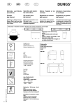
Betriebsanleitung / Instruction manual
EINBAUHINWEISE
INSTALLATION INSTRUCTIONS
Betriebsanleitung / Instruction manual
1. Allgemeine Informationen / General information
1.1 Vorabinformation / Preliminary Information:
Vor der Montage ist folgendes in jedem Fall zu überprüfen.
Before assembly please review the following steps carefully
• Das mitgelieferte Gutachten muss mit den technischen Daten des Fahrzeugs übereinstimmen (VA- und
HA-Last, Fahrzeug Typ Nr. und ABE EG Nr.).
The provided certificate has to match the technical data of the vehicle (max. perm. front– and rear-axle
load, vehicle identification number (VIN)) etc....).
• Die Fahrwerkskomponenten müssen mit dem Gutachten übereinstimmen (Feder - und Federbeinkennzeichnung, Kennzeichnung Hydraulik-Lift-System).
The coilover kit components have to coincide with the certificate (spring– and struts, manufacture markings, of the Hydraulic-Lift-System).
1.2 Inhalt dieser Betriebsanleitung / Contents of this instruction manual
Diese Betriebsanleitung beinhaltet die Montage, Inbetriebnahme und Wartung des KW Hydraulik Lift
Systems als Komplettsatz inklusive eines KW Gewindefahrwerks oder als Nachrüstsatz für ein bereits
vorhandenes KW Gewindefahrwerk. Sofern die Handhabung der Fahrwerkselemente nicht nachfolgend
beschrieben ist, werden alle Fahrwerkselemente gemäß den Richtlinien der Fahrzeughersteller aus- und
eingebaut.
This includes the installation, set up and maintenance of the KW hydraulic lift System, including a KW
coilover kit or as a retrofit kit for an existing KW coilover kit. Unless the handling of the suspension elements are not described in this manual, all chassis components installed in accordance with the guidelines of the vehicle manufacturers
1.3 Verwendung der Betriebsanleitung / Using the instruction manual
Diese Betriebsanleitung bezieht sich nur auf das in den nächsten Seiten genannte Fahrzeug. Eine Montage in ein anderes Fahrzeug ist nicht zulässig. Die Betriebsanleitung sollte stehts griffbereit im Fahrzeug
aufbewahrt werden. Der Inhalt der Betriebsanleitung muss vor jeder Montage, Demontage und Wartung
gelesen, verstanden und in allen Punkten befolgt werden.
The instructions of this manual refer only to the vehicle mentioned on the next pages. Installation on a
different vehicle is not permitted. The instruction manual should always be stored and available in the vehicle. Before any assembly, disassembly and maintenance, the contents of this instruction manual should
be read, understood and complied in all respects.
1.4 Teilegutachten / Part certificate
Die Hinweise im mitgelieferten Teilegutachten sind in jedem Fall folge zu Leisten. Die im Teilegutachten
beschriebenen Einstellwerte und Hinweise sind in jedem Fall zu befolgen. Diese Einstellwerte dürfen
weder unter- noch überschritten werden. Sollten die Einstellwerte aus dem Gutachten und der Betriebsanleitung nicht übereinstimmen, so sind immer die Werte im Gutachten maßgeblich.
The details in the provided parts certificate have to be adhered to in full. The settings and advice described in this part certificate have to be adhered to in full. The settings are not allowed to Neither undernor are exceeded. If the settings in the certificate don't match the ones in the instruction manual, the settings in the certificate should always prevail.
1.5 Qualifikation des Anwenders / Qualification of the user
Arbeiten an Fahrwerkskomponenten und hydraulischen Geräten dürfen nur von ausgebildetem Fachpersonal mit geeignetem Werkzeug ausgeführt werden!
Only qualified professionals with proper tools. are permitted to work on the coilover kit components and
on the hydraulic equipment
Betriebsanleitung / Instruction manual
1.6 Sicherheitshinweise / Safety Precautions MUST READ
In jedem Fall sind die aktuell geltenden Unfallverhütungsvorschriften für die jeweiligen Tätigkeiten
einzuhalten. Bei Nichteinhaltung dieser Vorschriften besteht Gefahr für Gesundheit und Leben!
Always follow the latest accident prevention regulations (not applicable for North America) for each
step to prevent any serious bodily harm or injury.
•
•
Bei Montagearbeiten am Fahrwerk, bei denen das Fahrzeug mittels Wagenheber angehoben wird,
ist das Fahrzeug mit handelsüblichen Unterlegkeilen gegen Wegrollen zu sichern! Zusätzlich ist
das angehobene Fahrzeug mittels Unterstellböcken gegen unbeabsichtigtes Herabsenken zu sichern!
We recommend the use of a vehicle hoist or lift when installing the suspension. If a lift is not available and jacking equipment is used, make sure that the vehicle is secured with commercial wheel
blocks and jack stands to ensure safety.
•
Die nachfolgend aufgeführten Montagehinweise sind unbedingt zu beachten!
The General Installation instructions, as well as the Technical inspection (German TÜV) documents
must be read BEFORE attempting installation.
•
Die Kolbenstangenbefestigungsmuttern dürfen niemals durch einen Schlagschrauber bewegt werden!
Never use impact wrenches or air guns to install or remove shock absorber piston hardware.
•
Explosionsgefahr!!! Stoßdämpfer und Stoßdämpfereinsätze dürfen auf keinen Fall zerlegt werden. Dämpfer steht unter Druck.
Danger Warning of Explosion!!! Never disassemble or cut open shock absorbers and/or shock
absorber inserts. Because they contain oil under high pressure.
•
Die Fahrwerk-Dämpfungsregelung (sofern vorhanden) muss durch eine Fachwerkstatt deaktiviert
werden!
The suspension regulation system (if any) needs to be disabled by an authorized dealer.
•
Grundsätzlich ist darauf zu achten, dass Passungen und Verschraubungen (z.B.: Befestigung des
Stoßdämpfergehäuses oder des unteren Traggelenkes im Radlagergehäuse) staub- und fettfrei
sind! (siehe Hersteller-Richtlinien).
Please take extra precautions that fittings (for example fittings of shock absorber housings or fittings of the lower control arms in the housing of the wheel bearing) are free of dust and oil. (see
manufacturers guideline)
Betriebsanleitung / Instruction manual
1.7 Symbole / Symbols
Die unten aufgeführten Sicherheitssymbole markieren in dieser Betriebsanleitung Tätigkeiten, bei denen
erhöhte Vorsicht geboten ist. Die vorgeschlagenen Sicherheitsvorkehrungen sollten in jedem Fall ein
gehalten werden.
The safety symbols below mark the actions in this manual where you have to pay special attention to.
The suggested safety precaution should be followed to in any case.
Sicherheitshinweise werden in dieser Anleitung mit diesem Symbol gekennzeichnet.
This Symbol Indicates safety precautions
Bei Textpassagen mit diesem Symbol besteht Quetschgefahr.
There is danger of injuring yourself in text areas marked with this symbol .
Augenschutz benutzen.
This symbol indicates. Use of eye protection.
i
Bei Textpassagen mit diesem Symbol geben wir Ihnen wichtige Informationen und Tipps.
Text areas marked with this symbol will give you important information and
tips.
Bei Textpassagen mit diesem Symbol sind allgemeine Montagehinweise.
Text areas marked with this symbol are general installation advice.
1.8 Haftungsausschluss / Disclaimer
Die Einhaltung dieser Betriebsanleitung und der Bedienung und Methoden der Installation, dem Betrieb
und der Wartung des KW Gewindefahrwerks mit dem Hydraulik-Lift-Systems können von der Firma KW
automotive GmbH nicht kontrolliert und überwacht werden. Daher übernehmen wir keinerlei Haftung und
Verantwortung für Schäden, die aus dem Betrieb oder falscher Handhabung und Wartung entstehen oder
in irgendeiner Art und Weise damit zusammenhängen. Die Firma KW automotive GmbH behält sich das
Recht vor, Änderungen der Betriebanleitung ohne vorherige Ankündigung oder Mitteilung vorzunehmen.
Compliance with these instructions and the handling methods of the installation, operation and maintenance. The usage and service of the KW coilover kits with the hydraulic-Lift-System can not be controlled
by KW automotive GmbH. Therefore, we assume no liability or responsibility for any damages resulting
from the operation or mishandling or lack of maintenance.. KW Automotive reserves the right, to change
this manual and/or update the product without any notice.
Urheberrecht / Copyright
Ohne ausdrückliche Genehmigung der Firma KW Automotive GmbH ist es nicht gestattet, die
Betriebsanleitung oder Teile daraus zu vervielfältigen oder in Zeitungen und Zeitschriften oder
anderen Medien zu verbreiten. Eine Überlassung an Dritte ist nur mit schriftlicher Genehmigung der
KW Automotive GmbH erlaubt.
It is not permitted to copy any part of this manual without the permission from KW Automotive GmbH .
Betriebsanleitung / Instruction manual
2. Montage KW Gewindefahrwerk / Installation of KW Coilover kit
2.1 Fahrzeugdaten / Vehicle data
Diese Betriebsanleitung ist nur für das in der Tabelle aufgeführtes Gewindefahrwerk und Fahrzeug gültig.
This manual is only valid for the coilover kit and the vehicle mentioned in the table below.
Gewindefahrwerk Artikel Nr.
Coilover kit part no.
Fahrzeugtyp / Vehicle Model
192 80 493
Seat Altea, Toledo (5P), Seat Leon (1P), VW Golf V, Golf VI (1K),
VW Golf V Plus, Cross Golf (1KP), VW Golf V Variant, Jetta (1KM),
VW Toran (1T)
2.2 Einstellwerte Gewindefahrwerk / Adjustment of the coilover kit
Fahrzeugtyp / Vehicle Model
Seat Altea, Toledo
Vorderachse /
Front axle
Hinterachse /
Rear axle
8022
1020
HLS Kennzeichnung / HLS Labeling
192 00 000
-
Federbein- (Dämpferkennzeichnung) /
Coilover strut (Shock absorber signature)
100 1007 /
100 1009
100 1107
Federkennzeichnung /
Spring Labeling
Zulässiges Abstandsmaß A /
Approximate Measurement distance A
min:
max:
min:
max:
250 mm
280 mm
17 mm
32 mm
Zulässiges Radmitte - Kotflügelunterkante Abstandsmaß B in mm /
Approximate measurement B in mm /
min:
min:
330 mm
335 mm
Fahrzeugtyp / Vehicle Model
Seat Leon
Vorderachse /
Front axle
Hinterachse /
Rear axle
8022
8101
HLS Kennzeichnung / HLS Labeling
192 00 000
-
Federbein- (Dämpferkennzeichnung) /
Coilover strut (Shock absorber signature)
100 1007 /
100 1009
100 1107
Federkennzeichnung /
Spring Labeling
Zulässiges Abstandsmaß A /
Approximate Measurement distance A
Zulässiges Radmitte - Kotflügelunterkante Abstandsmaß B in mm /
Approximate measurement B in mm /
min:
max:
min:
max:
250 mm
280 mm
12 mm
32 mm
min:
min:
Betriebsanleitung / Instruction manual
Fahrzeugtyp / Vehicle Model
VW Golf V
Vorderachse /
Front axle
Hinterachse /
Rear axle
8022
1020
HLS Kennzeichnung / HLS Labeling
192 00 000
-
Federbein- (Dämpferkennzeichnung) /
Coilover strut (Shock absorber signature)
100 1007 /
100 1009
100 1107
Federkennzeichnung /
Spring Labeling
Zulässiges Abstandsmaß A /
Approximate Measurement distance A
min:
max:
min:
max:
255 mm
285 mm
12 mm
32 mm
Zulässiges Radmitte - Kotflügelunterkante Abstandsmaß B in mm /
Approximate measurement B in mm /
min:
min:
330 mm
330 mm
Fahrzeugtyp / Vehicle Model
VW Golf V Variant
Vorderachse /
Front axle
Hinterachse /
Rear axle
8022
1020
HLS Kennzeichnung / HLS Labeling
192 00 000
-
Federbein- (Dämpferkennzeichnung) /
Coilover strut (Shock absorber signature)
100 1007 /
100 1009
100 1107
Federkennzeichnung /
Spring Labeling
Zulässiges Abstandsmaß A /
Approximate Measurement distance A
min:
max:
min:
max:
255 mm
285 mm
12 mm
32 mm
Zulässiges Radmitte - Kotflügelunterkante Abstandsmaß B in mm /
Approximate measurement B in mm /
min:
min:
330 mm
330 mm
Fahrzeugtyp / Vehicle Model
VW Golf V Plus
Vorderachse /
Front axle
Hinterachse /
Rear axle
8022
1020
HLS Kennzeichnung / HLS Labeling
192 00 000
-
Federbein- (Dämpferkennzeichnung) /
Coilover strut (Shock absorber signature)
100 1007 /
100 1009
100 1107
Federkennzeichnung /
Spring Labeling
Zulässiges Abstandsmaß A /
Approximate Measurement distance A
Zulässiges Radmitte - Kotflügelunterkante Abstandsmaß B in mm /
Approximate measurement B in mm /
min:
max:
min:
max:
255 mm
285 mm
12 mm
32 mm
min:
min:
320 mm
325 mm
Betriebsanleitung / Instruction manual
Fahrzeugtyp / Vehicle Model
VW Cross Golf
Vorderachse /
Front axle
Hinterachse /
Rear axle
8022
1020
HLS Kennzeichnung / HLS Labeling
192 00 000
-
Federbein- (Dämpferkennzeichnung) /
Coilover strut (Shock absorber signature)
100 1007 /
100 1009
100 1107
Federkennzeichnung /
Spring Labeling
Zulässiges Abstandsmaß A /
Approximate Measurement distance A
min:
max:
min:
max:
255 mm
285 mm
12 mm
32 mm
Zulässiges Radmitte - Kotflügelunterkante Abstandsmaß B in mm /
Approximate measurement B in mm /
min:
min:
330 mm
330 mm
Fahrzeugtyp / Vehicle Model
VW Golf V GTI
Vorderachse /
Front axle
Hinterachse /
Rear axle
8022
1020
HLS Kennzeichnung / HLS Labeling
192 00 000
-
Federbein- (Dämpferkennzeichnung) /
Coilover strut (Shock absorber signature)
100 1007 /
100 1009
100 1107
Federkennzeichnung /
Spring Labeling
Zulässiges Abstandsmaß A /
Approximate Measurement distance A
min:
max:
min:
max:
260 mm
290 mm
12 mm
32 mm
Zulässiges Radmitte - Kotflügelunterkante Abstandsmaß B in mm /
Approximate measurement B in mm /
min:
min:
320 mm
325 mm
Fahrzeugtyp / Vehicle Model
VW Golf 4motion
Vorderachse /
Front axle
Hinterachse /
Rear axle
8022
1020
HLS Kennzeichnung / HLS Labeling
192 00 000
-
Federbein- (Dämpferkennzeichnung) /
Coilover strut (Shock absorber signature)
100 1007 /
100 1009
100 1107
Federkennzeichnung /
Spring Labeling
Zulässiges Abstandsmaß A /
Approximate Measurement distance A
Zulässiges Radmitte - Kotflügelunterkante Abstandsmaß B in mm /
Approximate measurement B in mm /
min:
max:
min:
max:
250 mm
280 mm
17 mm
37 mm
min:
min:
320 mm
325 mm
Betriebsanleitung / Instruction manual
Fahrzeugtyp / Vehicle Model
VW Golf VI
Vorderachse /
Front axle
Hinterachse /
Rear axle
8022
8101
HLS Kennzeichnung / HLS Labeling
192 00 000
-
Federbein- (Dämpferkennzeichnung) /
Coilover strut (Shock absorber signature)
100 1007 /
100 1009
100 1107
Federkennzeichnung /
Spring Labeling
Zulässiges Abstandsmaß A /
Approximate Measurement distance A
min:
max:
min:
max:
255 mm
285 mm
20 mm
45 mm
Zulässiges Radmitte - Kotflügelunterkante Abstandsmaß B in mm /
Approximate measurement B in mm /
min:
min:
320 mm
320 mm
Fahrzeugtyp / Vehicle Model
VW Golf VI R
Vorderachse /
Front axle
Hinterachse /
Rear axle
8022
1020
HLS Kennzeichnung / HLS Labeling
192 00 000
-
Federbein- (Dämpferkennzeichnung) /
Coilover strut (Shock absorber signature)
100 1007 /
100 1009
100 1107
Federkennzeichnung /
Spring Labeling
Zulässiges Abstandsmaß A /
Approximate Measurement distance A
min:
max:
min:
max:
250 mm
280 mm
17 mm
37 mm
Zulässiges Radmitte - Kotflügelunterkante Abstandsmaß B in mm /
Approximate measurement B in mm /
min:
min:
320 mm
320 mm
Fahrzeugtyp / Vehicle Model
VW Jetta
Vorderachse /
Front axle
Hinterachse /
Rear axle
8022
1020
HLS Kennzeichnung / HLS Labeling
192 00 000
-
Federbein- (Dämpferkennzeichnung) /
Coilover strut (Shock absorber signature)
100 1007 /
100 1009
100 1107
Federkennzeichnung /
Spring Labeling
Zulässiges Abstandsmaß A /
Approximate Measurement distance A
Zulässiges Radmitte - Kotflügelunterkante Abstandsmaß B in mm /
Approximate measurement B in mm /
min:
max:
min:
max:
255 mm
285 mm
17 mm
37 mm
min:
min:
330 mm
330 mm
Betriebsanleitung / Instruction manual
Fahrzeugtyp / Vehicle Model
VW Touran
Vorderachse /
Front axle
Hinterachse /
Rear axle
8022
8007
HLS Kennzeichnung / HLS Labeling
192 00 000
-
Federbein- (Dämpferkennzeichnung) /
Coilover strut (Shock absorber signature)
100 1007 /
100 1009
100 1107
Federkennzeichnung /
Spring Labeling
Zulässiges Abstandsmaß A /
Approximate Measurement distance A
min:
max:
min:
max:
255 mm
285 mm
12 mm
37 mm
Zulässiges Radmitte - Kotflügelunterkante Abstandsmaß B in mm /
Approximate measurement B in mm /
min:
min:
340 mm
345 mm
Fahrzeugtyp / Vehicle Model
VW Golf V R32
Vorderachse /
Front axle
Hinterachse /
Rear axle
8022
1020
HLS Kennzeichnung / HLS Labeling
192 00 000
-
Federbein- (Dämpferkennzeichnung) /
Coilover strut (Shock absorber signature)
100 1007 /
100 1009
100 1107
Federkennzeichnung /
Spring Labeling
Zulässiges Abstandsmaß A /
Approximate Measurement distance A
min:
max:
min:
max:
255 mm
285 mm
17 mm
37 mm
min:
min:
320 mm
320 mm
A
A
A
A
B
Zulässiges Radmitte - Kotflügelunterkante Abstandsmaß B in mm /
Approximate measurement B in mm /
Abstandsmaß B - Radmitte Kotflügelunterkante
A
A
Distance dimension B - center of
wheel - lower edge of the fender
Abstandsmaß A aus Tabelle von 2.2 (Abbildungen nur symbolisch) /
Distance dimension A from table from 2.2 (for illustration purposes only)
Betriebsanleitung / Instruction manual
2.4 Mindestabstände zur Fahrbahnoberfläche / Minimum Ground clearance
Mindestabstände zur Fahrbahnoberfläche (Lichttechnische Einrichtungen gemäß ECE 48)
Minimum distance to ground surface (Installed lights accordingly ECE 48)
Scheinwerferaustrittskante / Head light outlet edge
500 mm
Blinker seitlich / Side indicator
350 mm
Nebelscheinwerfer / Fog lights
250 mm
Bremsleuchte / Brake light
350 mm
Kennzeichen vorne / Licence plate front
200 mm
Schlussleuchte / Tail lamp
350 mm
Kennzeichen hinten / Licence plate rear
300 mm
Nebelschlussleuchte / Fog tail lamp
250 mm
Blinker vorne / Indicator front
350 mm
Rückfahrscheinwerfer / reverse light
250 mm
Blinker hinten / Indicator rear
350 mm
Anhängerkupplung Kugelmitte /
Trailer hitch center of the ball
350 mm
2.5 Anzugsdrehmomente Kolbenstangenverschraubung /
Tightening torque of the piston rod fitting
Sofern nicht in der Betriebsanleitung beschrieben, müssen folgende Anzugsdrehmomente eingehalten werden:
If not described differently in the manual, you need to hold on to the following tightening torques:
Anzugsdrehmoment für Kolbenstangenverschraubung / Tightening torque for piston rod screwing:
M8 = 25 Nm, M10x1 = 20 Nm, M10x1,25 = 20 Nm, M12x1,25 = 35 Nm, M12x1,5 = 40 Nm, M14x1,5 = 50 Nm,
M16x1,5 = 50 Nm
2.6 Allgemeine Montagehinweise / General installation advice
•
Wir empfehlen dringend, die Fahrwerksmontage nur auf geeigneten und geprüften Hebebühnen durchzuführen.
We strongly recommend the use of a vehicle hoist or lift when installing the suspension.
•
Achtung! Falls das Fahrzeug mit Höhensensoren ausgestattet ist (Niveauregulierung,
Scheinwerferhöhenverstellung) sollten die Sensoren vor dem Ausbau der Federbeine bzw.
Stoßdämpfer demontiert werden, da diese sonst beschädigt werden können.
Caution: If the vehicle is equipped with ride height sensors, they should be removed before
removal of struts or dampers, otherwise damage may occur.
•
Die Federbeine sind anhand der Fahrzeughersteller-Richtlinien zu demontieren.
The struts should be removed as specified by manufacturer’s instructions.
•
Zum Zerlegen der Original-Federbeine sind die vom Fahrzeughersteller vorgeschriebenen
Montagewerkzeuge bzw. geeignete Federspanner zu verwenden.
Manufacturer recommended tools for removal of the original struts, or a suitable spring compressor, must be used in order to remove most factory mounted suspension systems.
•
Die angelieferten Federbeine bzw. die Tieferlegungskomponenten sind wie auf den nachfolgenden Seiten beschrieben zu montieren.
Mount the complete suspension system as described on the following pages.
•
Die Befestigungsmuttern der Kolbenstangen dürfen nur mit geeignetem Spezialwerkzeug
angezogen werden. Es darf keinesfalls ein Schlagschrauber verwendet werden. Die Kolbenstange darf niemals mit einer Zange oder ähnlichem festgehalten werden. Eine Beschädigung der Kolbenstange ist auf jeden Fall zu vermeiden, denn schon die kleinste Oberflächenverletzung führt zum Defekt und Gewährleistungsausschluss.
Never use impact drivers to install nuts on the piston rods as permanent damage may occur.
It is imperative that you do not damage the piston rod surface, through use of pliers etc, as
the smallest damage will result in seal damage, and will not be covered under warranty.
Betriebsanleitung / Instruction manual
•
Bei der Montage des Federbeins sollte das Abstandsmaß an jedem Federbein so eingestellt
werden, dass es einem Mittelmaß der Werte der in Punkt 2.2 aufgeführten Tabelle entspricht. Erst nach dem Ausrollen des Fahrzeugs und der erfolgreicher Überprüfung auf die
zulässigen Abstände zur Fahrbahnoberfläche (Punkt 2.4) sollte das Fahrzeug auf die gewünschte Höhe eingestellt werden. Beispiel: Bei einem angegebenem Abstandsmaß von 20
- 60 mm sollten 40 mm eingestellt werden.
By mounting the strut, the distance dimension at each strut should be adjusted, according to
the information mentioned in table at Point 2.2.
After freewheeling of the vehicle and the successful checking of the permissible distances to
the road surface (Point 2.4) the vehicle should be set up to the desired height.
Example: With a specified range of 20 - 60 mm (0.8 - 2.3 Inches), 40 mm (1.5 Inches) is
your height adjustment range.
•
Die Fahrwerkskomponenten sind anhand der Fahrzeughersteller-Richtlinien zu montieren.
Install the suspension components in the vehicle as specified by the vehicle manufacturers
guidelines.
•
Alle nicht in dieser Anleitung vorgegebenen Anzugsdrehmomente sind aus den Unterlagen
des Fahrzeugherstellers zu entnehmen und einzuhalten.
Except as noted, all torque values must comply with manufacturer recommended specifications.
•
Nach kompletter Montage des Fahrwerks ist das Fahrzeug im Werkstattbereich auszurollen.
Danach ist die Fahrzeughöhe zu prüfen und eine Korrektur gemäß Kundenwunsch durchzuführen. Achtung! Das Maß Radmitte - Kotflügelunterkante in der vorbenannten Tabelle ist in
jedem Fall einzuhalten. Weiterhin sind auch die Mindestabstände zur Fahrbahnoberfläche
einzuhalten, die in der auf Seite 4 aufgeführten Tabelle beschrieben sind.
Achtung! Beim Einstellen ist zu berücksichtigen, dass sich das Fahrzeug im Fahrbetrieb um
weitere 5 - 10 mm absenken kann.
After assembly and installation is completed, the vehicle should be rolled onto level
ground. Once on level ground, measure the vehicle height and adjust to the customer’s requirements, within the prescribed lowering range.
Caution: Wheel hub center—wheel arch maximum measurement in the table of page
3 must not be exceeded, also take into account minimum road clearances specified in
the table on page 7 (only valid for Germany!).
Caution: It is common for the vehicle suspensions to settle by an additional 5 - 10 mm (0.2 0.4 Inches)
Die Fahrwerksgeometrie ist gemäß Vorgaben des Fahrzeugherstellers neu einzustellen.
Sollten die Werte aufgrund einer erheblichen Höhenabweichung nicht einstellbar sein, so ist
ein optimaler Wert in der Nähe des Toleranzbereiches des Fahrzeugherstellers einzustellen.
The geometry of the suspension needs to be adjusted according to the regulations of the
vehicle manufacturer. If a value cannot be reached due to the difference in the height, a optimal value next to the tolerance range of the vehicle manufacturer needs to be adjusted.
i
•
Betriebsanleitung / Instruction manual
•
Überprüfung der Freigängigkeit von Rädern und Bereifung zu den Federbeinen
(Gewinderingen) sowie anderen Fahrwerks– und Karosserieteilen. Das Mindestabstandsmaß darf 5 mm nicht unterschreiten. Es ist gegebenenfalls mittels handelsüblicher (für das
Fahrzeug zugelassene) Distanzscheiben mit eigenem Gutachten oder fachgerechter Bearbeitung der Radläufe wieder herzustellen. Bei Federbeinkonstruktionen, bei denen sich Federbeine direkt neben dem Rad befinden, die aber keine Rad führende Eigenschaft haben,
ist das Fahrzeug mittels 100 mm hohen Unterlegkeilen über die Diagonale (z.B. vorne rechts
und hinten links) einzufedern. In dieser Position muss nun das vorgegebene Mindestabstandsmaß auch eingehalten werden. Durch diese Maßnahme kann auch die Freigängigkeit
der Bereifung zur Karosserie überprüft werden.
Achtung: Bei Verbundlenkerachsen ist diese Methode zur Beurteilung der Radfreigängigkeit
zur Karosserie nicht ausreichend. Hier muss das Fahrzeug bis zur maximalen Achslast beladen werden und im Fahrversuch die Radfreigängigkeit überprüft werden.
Examine the clearance between the tires and the suspension over the full range of motion of
the wheel. The minimum clearance between the suspension and the tire is 5 mm (0.20 Inches). If this clearance is less than 5 mm (0.2 Inches), wheel spacers may be necessary. With
strut designs that are located close to the wheel, but that have no steering functions, use 100
mm (3.9 Inches) spacers on diagonally opposed wheel (e.g. front right, rear left). In this position, you must be able to achieve the minimum clearance required. You can also check the
clearance between tire and body.
Caution: With torsion beam trailing arm axles, this method is not sufficient. The wheel must
be under full load as well as test driven to properly calculate the clearances of 5 mm (0.2
Inches) from any other components.
•
Abschließend müssen noch alle mit der Fahrzeughöhe in Verbindung stehenden Komponenten (z.B. Scheinwerfer, Bremskraftregler usw.) gemäß Vorgaben des Fahrzeugherstellers
eingestellt werden.
All components that are controlled by vehicle ride height (e.g. headlights, brake bias regulator etc.) must be adjusted as specified by the vehicle manufacturer instructions and procedures.
•
Der Verstellfederteller ist durch Anziehen der vormontierten Innensechskantschraube zu sichern. Bei Federn mit separaten Höhenverstellungen (keine Federbeine) ist ein Sichern des
Gewinderings gegen verdrehen nicht notwendig.
Achtung! Das Anzugsdrehmoment (Innensechskantschraube) von max. 1 - 2 Nm muss eingehalten werden.
Ensure that the set screw on each spring collar is tightened to prevent movement of
the spring perch. On vehicles with separate shock/spring combinations, no set screw
is necessary. Caution: Do not over tighten the set screw. Maximum torque is 1 - 2
Nm (0.74-1.47 ft-lb).
Betriebsanleitung / Instruction manual
2.7 Montage Vorderachse / Front axle Installation
Alle Teile von dem bereits verbauten Federbein demontieren. Anschließend sollte das Federbein gründlich gereinigt
werden.
Remove all part of the installed coilover strut. After the
disassembly clean all part of the coilover strut.
Mitgelieferten HLS Ringzylinder, Feder und Anschlagelement mit Staubschutz auf das Federbein aufstecken. Zusätzlich auch das KW Zusatzanschlagelement wieder montieren (wenn vorhanden).
Insert the supplied HLS ring zylinder, spring and
bumpstopp with dust cover on the coilover strut. Addition
install the small bumpstopp (if available).
HLS Ringzylinder so positionieren, dass dieser mit der
Hydraulikverschraubung zur Fahrzeugheckseite innen
zeigt.
Mount the HLS cylinder line connection inside the rear of
the vehicle. Position the cylinder inward facing the middle
of the car
Das Original Domlager aufsetzen und mit der Original Mutter verschrauben. Das Anzugsdrehmoment der Kolbenstangenbefestigung beträgt 50 Nm. Die Montagehinweise zum Einbau des Federbein in das Fahrzeug, sowie die Anzugsdrehmomente der
Federbeinbefestigung, entnehmen Sie bitte den Unterlagen des Fahrzeugherstellers.
Attach the original top mount and fix it with the standard nut. Tightening torque for the
piston rod is 50 Nm (37 ft-lb). Please install the strut unit to manufacturers recommended settings regarding tightening torque and fixing specifications.
Nach erfolgtem Einbau des Fahrwerkes ist die Freigängigkeit der Bereifung zum VA-Federbein zu überprüfen.
Das Mindestabstandsmaß darf an der engsten Stelle 5 mm nicht unterschreiten und ist gegebenenfalls mittels handelsüblicher, TÜV geprüfter Distanzscheiben wieder herzustellen.
After you have completed installation of the suspension, check the clearance of the tyres to the front suspension strut. The minimum clearance at the narrowest point is 5 mm and must, where necessary, be provided
using commercially available, Technical Inspectorate (German TUEV) approved spacers.
Betriebsanleitung / Instruction manual
2.8 Montage Hinterachse / Rear axle Installation
Mitgelieferte Hydraulik Höhenverstellung wird ohne Gummiunterlage zwischen
Karosserie und Feder oben montiert. Hydraulik Höhenverstellung so positionieren, dass diese mit der Hydraulikverschraubung zur Fahrzeugheckseite außen
zeigt.
Mount the supplied hydraulic height adjuster without rubber support between the
body and the upper end of the spring. Mount the hydraulic height adjuster line
connection outside the rear of the vehicle.
Am unteren Ende der Feder wird
die originale Federunterlage weiterverwendet.
Use the original spring support at
the bottom end of the spring.
Betriebsanleitung / Instruction manual
3. Montage Hydraulik-Lift-System / Hydraulic-Lift-System installation
3.1 Sicherheitshinweise / Safety advice
•
Die Inbetriebnahme, Einsatz und die Verwendung des Hydraulik-Lift-Systems darf nur in Verbindung mit dem mitgelieferten Fahrwerk erfolgen.
The installing and using of the Hydraulic-Lift-System may only be done with the supplied coilover
kit.
•
Ohne angeschlossene Hydraulikleitungen darf das System nicht an die Stromversorgung angeschlossen werden.
The System may not be connected on the electric power supply without first connecting the hydraulic lines.
•
Arbeiten an Hydraulischen Anlagen (HLS) dürfen nur von hierfür geschultem und unterwiesenem
Personal mit den hierfür erforderlichen Kenntnissen durchgeführt werden.
Only qualified personnel with the essential knowledge may work on the hydraulic equipment (HLS).
•
Arbeiten an der Hydraulikeinheit und am Federbein darf nur im spannungslosen und drucklosen
Zustand und bei ausgeschalteter Hydraulikeinheit erfolgen. Die Hydraulikeinheit muss hierbei gegen Einschalten gesichert werden. Hierzu ist die Komplette Hydraulikeinheit inklusive der Steuerung von der Batterie abzuklemmen und die Anschlussleitung gegen Kontakt mit der Batterie zu
isolieren.
You may only work on the hydraulic units and on the strut in dead-voltage and depressurized while
the hydraulic unit is turned off. Make sure the hydraulic unit doesn't turn on.
•
Achtung Quetschgefahr !!! Ist das Fahrzeug mittels des Hydraulik-Lift-Systems angehoben, dürfen keine Montagearbeiten am Fahrzeug durchgeführt werden.
Attention: Danger of Injury. When the vehicle is lifted with the Hydraulic-Lift-System, you may not
do any other work on the car.
•
Vor Arbeiten am HLS System sind alle Druckleitungen und Ringzylinder drucklos zu machen.
Before demounting make sure all pressure lines and ring cylinders are without pressure.
•
Die Hydraulikeinheit und Ringzylinder können bei mehrmaligem auf - und absenken heiß werden.
The Hydraulic unit and the ring cylinder may get very! hot if you lift and lower the car several times
in a row.
•
Beim Umgang mit Hydrauliköl sind die für hierfür aktuell geltenden Sicherheitsbestimmungen zu
beachten und einzuhalten.
When using the Hydraulic oil, pay attention to the handling and safety regulation Please make sure
of this!
•
Unter Druck herausspritzendes Hydrauliköl kann zu schweren Verletzungen führen. Bei der Überprüfung auf Dichtheit muss eine entsprechende Schutzausrüstung (Schutzbrille usw.) getragen
werden.
If the oil spills out under pressure, it may cause heavy injury. You need to wear special safety goggles when you check the tightness.
•
Bei einem Ausfall der Spannungsversorgung senkt sich das Fahrzeug auf Normalzustand ab.
A failure of the power supply lowers the vehicle to the normal height.
•
Achtung! Bitte beachten Sie vor dem abklemmen der Stromversorgung (Batterie) die vom Fahrzeughersteller hierfür geltenden Hinweise.
Attention! Please note the vehicle manufacturers references before disconnecting the power supply
(battery).
Betriebsanleitung / Instruction manual
3.2 Montage / Installation
Montageposition /
Assembly
position
Erläuterung / Explanation
1
HLS Ringzylinder rechts
HLS Ring cylinder right
2
HLS Ringzylinder links
HLS Ring cylinder left
3
Hydraulikaggregat
Hydraulic aggregate
4
Verteiler
T-splitter
5
Hydraulikleitung 1900 mm
Verbindung Ringzylinder - Verteiler
Hydraulic line 1900 mm between the
ring cylinder and the t-splitter
6
Hydraulikleitung 1100 mm
Verbindung Hydraulikaggregat - Verteiler
Hydraulic line 1100 mm between
hydraulic aggregate and t-splitter
7
CAN Kommunikation Verbindung
Fahrzeug - Hydraulikaggregat
CAN Database between the vehicle
to the hydraulic aggregate
8
Innenraumtaster
Inside cabin button
9
HLS Ringzylinder rechts
HLS Ring cylinder right
10
HLS Ringzylinder links
HLS Ring cylinder left
11
Hydraulikleitung 2900 mm
Verbindung Ringzylinder - Verteiler
Hydraulic line 2900 mm between ring
cylinder and t-splitter
12
Hydraulikleitung 1100 mm
Verbindung Ringzylinder - Hydraulikaggregat
Hydraulic line 1100 mm between ring
cylinder and hydraulic aggregate
13
Hydraulikleitung 1250 mm Verbindung Verteiler - Hydraulikaggregat
Hydraulic line 1250 mm between
hydraulic aggregate and hydraulic
aggregate
14
Batterie
Battery
14
2
1
6
5
7
8
4
11
12
9
10
13
3
Montagposition
Assembly position
Betriebsanleitung / Instruction manual
Montage Hydraulikaggregat / Assembly of the hydraulic aggregate
Montageposition 3 / Assembly position 3
Styroporwanne demontieren.
ACHTUNG: Evtl. kann das Hydraulikaggregat an einer anderen
Position montiert werden.
Hydraulikleitungen werden in
einer Überlänge ausgeliefert.
Diese müssen wie in Anlage 1
beschrieben gekürzt und montiert werden.
Disassemble the styrofoam
tank.
Attension: It ist possible to
mount the hydraulic aggregate
elsewhere. The hydraulic lines
are delivered in an extra-long.
These must be reduced and
mounted as described in attachment 1.
Montageposition 3 / Assembly position 3
Styroporwanne wenden und umrisse des Hydraulikaggregates an der
Wanne markieren.
Anschließend die Markierung
passgenau ausschneiden.
Turn the styrofoam tank and mark
the outlines of the hydraulic aggregate on the styrofoam tank.
Cut out the styrofoam tank accurately.
Betriebsanleitung / Instruction manual
Montageposition 3 / Assembly position 3
Styroporwanne wieder montieren.
Reassemble the styrofoam
tank.
Mitgeliefertes Hydraulikaggregat in
den ausschnitt der Styroporwanne
eindrücken und mit Klettband befestigen.
Insert the hydraulic aggregate into
the styrofoam tank and fix in on the
bottom side with a velcro strip
Betriebsanleitung / Instruction manual
Verlegung der Hydraulikleitung Vorderachse rechte Fahrzeugseite /
Connecting the hydraulic pipe front right side of the vehicle
Sollte es vorkommen, dass die Hydraulikleitung über einer scharfen Kante
verläuft ist die Hydraulikleitung mit einem Spiralband zu schützen.
On sharp edges or scour marks please wrap the hydraulic line with a spiral
tube.
ACHTUNG: Räder geradeaus einschlagen.
Attention: place the wheels straight ahead.
Montageposition 1 / Assembly position 1
Hydraulikleitung (1100 mm) am
HLS Ringzylinder mit der mitgelieferten Hohlschraube und 2 Dichtscheiben montieren.
HLS Ringzylinder so positionieren,
dass dieser mit der Hydraulikverschraubung zur Fahrzeugheckseite innen zeigt.
Mount the hydraulic line (1100
mm) on the HLS Ring cylinder with
the supplied hollow bolt and 2 gaskets.
Mount the HLS cylinder line connection inside the front of the vehicle. Position the cylinder inward
facing the middle of the car.
Betriebsanleitung / Instruction manual
Vor endgültiger Befestigung der Hydraulikleitung, muss auf eine ausreichende Schleifengröße geachtet werden. Die Schleifengröße muss so gewählt
werden, dass diese über den kompletten Arbeitsbereich des Federbeines
nicht gespannt oder abgeknickt werden kann.
Before final fixing of the hydraulic line, make sure a sufficient loop size has
to been achieved. By choosing the size of the loop you need to make sure
that the complete work area of the strut won't be kinked or bent.
Montageposition 1 / Assembly position 1
Hydraulikleitung mit Klebesockel und
Kabelbinder verlegen. Kabelbinder
erst nach vollständiger Leitungsverlegung festziehen
Run the hydraulic line with the supplied adhesive mount and cable ties
on the chassis.
Tighten the cable ties after fully laying the cable.
Schleife /
Loop
Betriebsanleitung / Instruction manual
Hydraulikleitung (1100 mm) mit dem Verteiler verbinden. Anschließend Hydraulikleitung mit den mitgelieferten Klebesockel am Fahrzeug befestigen.
Montageposition 1 / Assembly position 1
Verteiler erst anklebe und verschrauben wenn die Leitungen angezogen
sind. WICHTIG: Oberfläche muss
Staub– und Fettfrei sein.
Connect the hydraulic line (1100 mm) on
the T-splitter. Fix the adhesive mount
after completion of the full cable mounting.
After tighten the hydraulic line fix the
T-Splitter on the vehicle. IMPORTANT:
Surface must be cleaned and degreased.
Montageposition 4 / Assembly position 4
Verteiler / T-splitter
Betriebsanleitung / Instruction manual
Verlegung der Hydraulikleitung Vorderachse linke Fahrzeugseite /
Connecting the hydraulic pipe on the front left side of the vehicle
Sollte es vorkommen, dass die Hydraulikleitung über einer scharfen Kante
verläuft oder an der Karoserie scheuert, ist die Hydraulikleitung mit einem
Spiralband zu schützen.
Please wrap sharp edges or scour marks on the hydraulic line with a spiral
tube.
ACHTUNG: Räder geradeaus einschlagen.
Attention: place the wheels straight ahead.
Montageposition 2 / Assembly position 2
Hydraulikleitung (1900 mm) am HLS
Ringzylinder mit der mitgelieferten Hohlschraube und 2 Dichtscheiben montieren.
HLS Ringzylinder so positionieren, dass
dieser mit der Hydraulikverschraubung
zur Fahrzeugheckseite innen zeigt.
Mount the hydraulic line (1900 mm) on
the HLS Ring cylinder with the supplied
hollow bolt and 2 gaskets.
Mount the HLS cylinder line connection
inside the front of the vehicle. Position
the cylinder inward facing the middle of
the car.
Betriebsanleitung / Instruction manual
Vor endgültiger Befestigung der Hydraulikleitung, muss auf eine ausreichende Schleifengröße geachtet werden. Die Schleifengröße muss so gewählt
werden, dass diese über den kompletten Arbeitsbereich des Federbeines
nicht gespannt oder abgeknickt werden kann.
Before final fixing of the hydraulic line, make sure a sufficient loop size has
to been achieved. By choosing the size of the loop you need to make sure
that the complete work area of the strut won't be kinked or bent.
Montageposition 2 / Assembly position 2
Hydraulikleitung mit Klebesockel und
Kabelbinder verlegen. Kabelbinder
erst nach vollständiger Leitungsverlegung festziehen
Run the hydraulic line with the supplied adhesive mount and cable ties
on the chassis.
Tighten the cable ties after fully laying the cable.
Schleife /
Loop
Betriebsanleitung / Instruction manual
Montageposition 2 / Assembly position 2
Hydraulikleitung (1900 mm) unter dem
Hitzeblech verlegen und mit dem Verteiler verbinden. Anschließend Hydraulikleitung mit den mitgelieferten Klebesockel
am Fahrzeug befestigen.
Verteiler erst anklebe und verschrauben wenn die Leitungen angezogen
sind. WICHTIG: Oberfläche muss
Staub– und Fettfrei sein.
Run the hydraulic line (1900 mm) behind
the heat absorber sheet and connect the
hydraulic line on the T-splitter. Fix the
adhesive mount after completion of the
full cable mounting.
After tighten the hydraulic line fix the
T-Splitter on the vehicle. IMPORTANT:
Surface must be cleaned and degreased.
Montageposition 4 / Assembly position 4
Verteiler /
T-splitter
Betriebsanleitung / Instruction manual
Verlegung der Hydraulikleitung Verteiler zum Hydraulikaggregat /
Connecting the hydraulic pipe from the t-splitter to the hydraulic aggregate
Sollte es vorkommen, dass die Hydraulikleitung über einer scharfen Kante
verläuft oder an der Karoserie scheuert, ist die Hydraulikleitung mit einem
Spiralband zu schützen.
On sharp edges or scour marks please wrap the hydraulic line with a spiral
tube
Montageposition 4 / Assembly position 4
Verteiler /
T-splitter
Hydraulikleitung (2900 mm) mit dem
Verteiler verbinden.
Anschließend Hydraulikleitung mit
Klebesockel und Kabelbinder am
Fahrzeug befestigen und in den Kofferraum verlegen.
Verteiler erst nach Fertigstellung
ankleben. WICHTIG: Oberfläche
muss Staub– und Fettfrei sein.
Connect the hydraulic line (2900 mm)
on the T-splitter. Run the hydraulic
line into the trunk and fix it on the vehicle with the adhesive mount and
cable ties.
Montageposition 11 / Assembly position 11
After completion fix the T-splitter
on the vehicle. IMPORTANT: Surface must be cleaned and degreased.
Betriebsanleitung / Instruction manual
Montageposition 11 / Assembly position 11
Hydraulikleitung durch den serienmäßigen Stopfen verlegen und mit Kabelbinder befestigen. Hierzu muss die Öffnung
eingeschnitten werden
Run the Hydraulic along the standard
plug and secure it with cable ties. For this
cut a small hole into the plug.
Montageposition 3 / Assembly position 3
Absperrstopfen herausdrehen.
Remove the plug.
Betriebsanleitung / Instruction manual
Montageposition 3 / Assembly position 3
Mitgelieferten Anschlussadapter mit einer
Dichtscheibe montieren.
Mount the supplied connection adapter
with 1 gasket.
Dichtscheibe /
Gasket
Montageposition 3 / Assembly position 3
Hydraulikleitungen werden in einer
Überlänge ausgeliefert. Diese müssen
wie in Anlage 1 beschrieben gekürzt
und montiert werden.
Anschließend Hydraulikleitung an dem
zuvor montierten Adapter aufdrehen.
The hydraulic lines are delivered in an
extra-long. These must be reduced
and mounted as described in attachment 1.
Mount the hydraulic line on the hydraulic
adapter.
Betriebsanleitung / Instruction manual
Verlegung der Hydraulikleitung Hinterachse rechte Fahrzeugseite /
Connecting the hydraulic pipe on the rear right side of the vehicle
Sollte es vorkommen, dass die Hydraulikleitung über einer scharfen Kante
verläuft, ist die Hydraulikleitung mit einem Spiralband zu schützen.
On sharp edges or scour marks please wrap the hydraulic line with a spiral
tube.
Montageposition 9 / Assembly position 9
Hydraulikleitung (1250 mm) am HLS
Ringzylinder mit der mitgelieferten Hohlschraube und 2 Dichtscheiben montieren.
HLS Ringzylinder so positionieren, dass
dieser mit der Hydraulikverschraubung
schräg zur Fahrzeugheckseite außen
zeigt.
Mount the hydraulic line (1250 mm) on
the HLS Ring cylinder with the supplied
hollow bolt and 2 gaskets.
Mount the HLS cylinder line connection
inside the back of the vehicle. Position the
cylinder facing the outside back of the car.
Betriebsanleitung / Instruction manual
Hydraulikleitung in den Kofferraum verlegen und mit den mitgelieferten Kabelbinder befestigen. Kabelbinder erst
nach vollständiger Leitungsverlegung festziehen.
Run the hydraulic line through the hole into the trunk and fix the hydraulic line on the strut with the supplied cable ties. Tighten the cable ties after completion of the full cable laying.
Montageposition 12 / Assembly position 12
Betriebsanleitung / Instruction manual
Verlegung der Hydraulikleitung Hinterachse links Fahrzeugseite /
Connecting the hydraulic pipe on the rear left side of the vehicle
Sollte es vorkommen, dass die Hydraulikleitung über einer scharfen Kante
verläuft, ist die Hydraulikleitung mit einem Spiralband zu schützen.
On sharp edges or scour marks please wrap the hydraulic line with a spiral
tube.
Hydraulikleitung (1250 mm) am HLS
Ringzylinder mit der mitgelieferten Hohlschraube und 2 Dichtscheiben montieren.
HLS Ringzylinder so positionieren, dass
dieser mit der Hydraulikverschraubung
schräg zur Fahrzeugheckseite außen
zeigt.
Montageposition 10 / Assembly position 10
Mount the hydraulic line (1250 mm) on
the HLS Ring cylinder with the supplied
hollow bolt and 2 gaskets.
Mount the HLS cylinder line connection
inside the back of the vehicle. Position the
cylinder facing the outside back of the car.
KW automotive GmbH • Aspachweg 14
D-74427 Fichtenberg
Tel: +49 (0) 7971/9630-0
Fax: +49 (0) 7971/9630-191
www.kwautomotive.de
[email protected]
Nr. / No. 192 80 491
Stand / Version 21.02.2013
Seite / Page 31
© KWautomotive GmbH
Betriebsanleitung / Instruction manual
Hydraulikleitung in den Kofferraum verlegen und mit den mitgelieferten Kabelbinder befestigen. Kabelbinder erst
nach vollständiger Leitungsverlegung festziehen.
Run the hydraulic line through the hole into the trunk and fix the hydraulic line on the strut with the supplied cable ties. Tighten the cable ties after completion of the full cable laying.
Montageposition 11 / Assembly position 11
Betriebsanleitung / Instruction manual
Anschluss Hydraulikleitung der HA Ringzylinder /
Connecting the hydraulic line from the rear axle hydraulic zylinder
Montageposition 3 / Assembly position 3
Absperrstopfen herausdrehen.
Remove this plug.
Montageposition 3 / Assembly position 3
Hydraulikleitungen werden in einer
Überlänge ausgeliefert. Diese müssen wie in Anlage 1 beschrieben
gekürzt und montiert werden.
Beide Hydraulikleitungen (1100 mm
und 1250 mm) mit 3 Dichtscheiben
montieren.
The hydraulic lines are delivered in
an extra-long. These must be reduced and mounted as described
in attachment 1.Mount the supplied
hydraulic lines (1100 mm and 1250
mm) with 3 gaskets.
Betriebsanleitung / Instruction manual
Hydraulikleitungen entlang der VA Hydraulikleitung verlegen und mit Kabelbinder befestigen.
Run the hydraulic lines along the front axle hydraulic line and fix it with cable ties.
Montageposition 3 / Assembly position 3
Betriebsanleitung / Instruction manual
3.3 Verdrahtung / Wiring
Beachten Sie folgende Hinweise:
Nicht fachgerechte Kabelverlegungen und Kabelverbindungen können zu Fehlfunktionen oder Beschädigungen von Bauteilen führen. Eine korrekte Kabelverlegung bzw. Kabelverbindung ist die Grundvoraussetzung für eine dauerhafte und fehlerfreie Funktion.
Rote Klemme 30
Die Leitung muss mit einer Sicherung direkt an der Batterie angeschlossen werden.
Blaue Klemme 31
Die Leitung muss an Masse angeschlossen sein.
Vorzugsweise ist das Kabel direkt an der Batterie oder an einen dafür vorgesehenen Massepunk an der Karosserie anzuschließen.
Please pay attention to the following advice:
Failures or damages of unit may occur due to unprofessional cable laying and cable connections. By correct cable laying and cable connecting is the basic requirement for long and accurate functionality.
Red clamp 30
The wire has to be connected with a fuse directly on the battery.
Blue clamp 31
The wire has to be connected to the mass.
In best case connect the cable directly on the battery or on the mass point of the vehicle
body.
Betriebsanleitung / Instruction manual
CAN Anbindung / CAN connection
Mitgelieferte CAN Leitung inkl. Tasterleitung in das HLS Steuergerät einstecken und Stecker verriegeln.
Beide Leitungen mit den mitgelieferten Klebesockel am Kofferraumboden befestigen.
Put the supplied CAN wire with the inside cabin buttiom wire into the HLS control unit and lock the connector.
Fix the CAN wire with the supplied adhesive mount on the bottom sheet of the trunk.
Montageposition 3 / Assembly position 3
Betriebsanleitung / Instruction manual
CAN Leitung und Tasterleitung auf der linken Fahrzeugseite zur Fahrzeugvorderseite verlegen. Kabel mit den
mitgelieferten Edge Clips am Radhaus befestigen.
Run the CAN wire with the inside cabin buttiom wire on the left vehicle side to the front of the car. Fix the cables
wit the supplied edge clips on the wheelhouse.
Montageposition 3 / Assembly position 3
Betriebsanleitung / Instruction manual
Montageposition 7 / Assembly position 7
Türkabelbaum trennen und Buchse aus der
A-Säule herausziehen.
Disconnect the door wire harness and remove the female connector out of the APillar.
Betriebsanleitung / Instruction manual
Auf die richtige Verdrahtung achten!!!
Pay attention to the correct connection!!!
Stecker entriegeln.
1: Lasche nach unten drücken.
2: Riegel eine raste nach außen ziehen.
ACHTUNG: Nach dem Entriegeln können alle Pins aus dem Stecker herausfallen.
Montageposition 7 / Assembly position 7
Unlock the connector.
1: Press the latch downwards.
2: Pull the latch one notch to the outside.
Attention: After the unlocking the pins
might fall out of the connector.
2
1
Betriebsanleitung / Instruction manual
Montageposition 7 / Assembly position 7
ACHTUNG: Kabelfarbe und zugehörige
Pinnummer bitte vor dem herausziehen
der Pins notieren.
Pin 4 (orange/grün) und Pin 5 (orange/
braun) aus dem Stecker auspinnen.
Attention: Before removal of the pins
make a note about the cable pin and the
cable color.
Remove Pin 4 (orange/green) and Pin 5
(orange/brown) out of the connector.
Herausgepinnte Kabel in den mitgelieferten
Stecker einstecken
Ausgepinntes Kabel aus Pin 4 in den mitgelieferten Stecker Pin 1 einstecken.
Ausgepinntes Kabel aus Pin 5 in den mitgelieferten Stecker Pin 2 einstecken
Insert the removed pins into the
Connector.
Connect the removed Pin 4 into the
connector Pin 1.
Connect the removed Pin 5 into the
connector Pin 2 (white wire)..
Betriebsanleitung / Instruction manual
Montageposition 7 / Assembly position 7
Anschließend die vom mitgelieferten CAN
Kabel abgehenden Kabel braun und weiß
in den Originalstecker einstecken.
Kabelfarbe weiß in Pin 4 Original Stecker
einstecken.
Kabelfarbe braun in Pin 5 Original Stecker
einstecken.
Connect the pins out of the supplied CAN
wire white and brown into the standard
connector.
Cable color white into Pin 4 standard
connector.
Cable color brown into Pin 5 standard
connector.
Stecker wieder einstecken und
CAN Kabel mit Kabelbinder befestigen.
Connect the connector and fix the
CAN wire with cable ties.
Betriebsanleitung / Instruction manual
Anschluss Innenraumtaster / Connection the Interior room button
Tasterkabel hinter das Armaturenbrett verlegen.
Run the inside cabin buttom wire behind the
dashboard.
Montageposition 8 / Assembly position 8
Möglicher Montageort.
Assembly position.
Betriebsanleitung / Instruction manual
4-Adrige Leitung auf passende Länge kürzen, abisolieren und Aderendhülsen anbringen
Cut the 4 wire cable to the correct length and remove the insulation.
Mount the supplied core cable ends on the cable
with the correct tool.
40 mm
Für die Montage des Tasters muss ein Loch in das
Armaturenbrett gebohrt werden.
Montageposition 8 / Assembly position 8
Achtung: Es können Leitungen unter dem Armaturenbrett vorhanden sein.
Drill a hole into the dashboard for mounting the button.
IMPORTANT: Please make sure to detach the
electrical wires below the dashboard.
Leitungen an den Verschraubungen montieren.
LED +5V
Kabelfarbe
Tasteranschluss
Orange
LED +5V Einprägung (+)
Schwarz
LED - Einprägung (-)
Braun / rot
Taster
Connect the cables on the screw connections.
LED Cable colour
Button connection
Orange
LED +5V label (+)
Black
LED - label (-)
Brown / red
Button
Betriebsanleitung / Instruction manual
Anschluss Spannungsversorgungsleitung / Connecting the power supply
Montageposition 3 / Assembly position 3
Spannungsversorgungsleitung mit dem Hydraulikaggregat aus dem Fahrzeug führen und
durch die linke Öffnung nach unten herauslegen.
Connect the power supply cable on the hydraulic aggregate and run the cable out of the rear
trunk.
Spannungsversorgungsleitung an der Achse
befestigen und an der Bremsleitung zur Fahrzeugvorderseite verlegen.
Fix the power supply cable on the brake line
and run the cable to the front of the vehicle.
Betriebsanleitung / Instruction manual
Montageposition 3 / Assembly position 3
Spannungsversorgungsleitung bis zur Batterie verlegen und auf entsprechende länge kürzen.
Run the power supply cable to the battery
and cut the cable to the correct length.
Masseleitung (blau) 8 mm abisolieren und
mitgelieferten Kabelschuh mit geeignetem
Werkzeug an der Masseleitung (blau) montieren.
4- 6mm²
Remove 8 mm of the insulation from the 4
wire cable and mount the supplied cable
connector with a correct tool.
Plusleitung (rot) bei Bedarf kürzen.
If necessary cut the red wire to the correct
length.
Aderabdichtung auf die Plusleitung aufstecken, Leitung 6 mm abisolieren und Kontakt mit einem geeignetem Werkzeug montieren.
4- 6mm²
Install the cable seal on the plus cable and
remove 6 mm / 0,24“ of the red (plus) cable
insulation. Install the supplied pin contact
with a correct tool.
Betriebsanleitung / Instruction manual
Plusleitung (rot) 8 mm abisolieren und
mitgelieferten Kabelschuh mit geeignetem Werkzeug montieren.
Remove 8 mm / 0,31“ of the insulation
from the positive wire and mount the supplied cable connector with a correct tool.
4- 6mm²
Sicherungshalter /
Fuse holder
Fertig montierte Plusleitung in den Sicherungshalter einrasten.
Install the positive wire into the fuse holder. Press the cable into the hole.
Klick / Click
Sicherungshalter verriegeln.
Hierzu muss die gelbe Sicherung nach
unten gedrückt werden.
Lock the fuse holder.
Press the yellow locking device into the
fuse holder.
Montageposition 3 / Assembly position 3
Montageposition 3 / Assembly position 3
Plusleitung am Plusverteiler und die
Masseleitung am Zentralen Massepunkt
anschließen.
Connect the mass and the plus wire.
Betriebsanleitung / Instruction manual
3.4 Fernbedienung / Remote Control
Kontroll-LED: Diese LED signalisiert das Senden an das Hydraulik-Lift-System
Taster: Dieser Taster dient dazu das Fahrzeug anzuheben oder abzusenken.
Lässt die Reichweite des Handsenders merklich nach oder flackert die Kontroll-LED beim Senden, so
muss die Batterie ausgetauscht werden. Drücken Sie mit einem flachen Gegenstand an der Einkerbung
den Handsender vorsichtig auseinander und öffnen Sie den Sender. Tauschen Sie die Batterie. Achten
Sie beim Einlegen der Batterie auf die richtige Polung (Batterietyp CR 2032 3 Volt). Der Plus-Pol ist oben.
Erhältlich ist die Batterie z. B. in Fotoläden, Uhrengeschäften, usw. Setzen Sie den Deckel des
Handsenders wieder auf und drücken ihn mit einem hörbaren Klick wieder zusammen. Verwenden Sie
nur auslaufsichere und für elektronische Geräte geeignete Batterien. Halten Sie die Batterien außer
Reichweite von Kindern. Versuchen Sie nie Batterien wieder aufzuladen, zu öffnen oder ins Feuer zu
werfen.
Control-LED: This LED signalizes the sending to the Hydraulic-Lift-System
Button: This button will allow the car lift and lower
If the coverage of the remote control looses or if the control-LED jitters while sending, the battery has to
be changed.
Use a flat item to press the notch of the remote control carefully apart and open the sender. Change the
batteries. Make sure while changing them you will connect the right terminals way. (Battery type CR 2032
3 Volt).
The positive polarity is on the top. You can get the battery from any local KW dealer. Put the lid back on
the remote control and press it together. You will hear a click. Only use leak proofed batteries which are
suitable for electronic equipments. Take the batteries out of the reach of children. Never try to reload batteries, open, or throw them into a fire.
.
Kontroll-LED
Control-LED
Taster
Button
Lasche
Plate
Einkerbung
Notch
Betriebsanleitung / Instruction manual
3.5 Inbetriebnahme und Bedienung des Hydraulik-Lift-System /
Startup and operartion of the Hydraulic-Lift-System
Vor der Inbetriebnahme ist eine Optische Sichtprüfung aller Hydraulikleitungen und der
Spannungsversorgungsleitungen zu empfehlen.
Nach abgeschlossener Sichtprüfung sind folgende Schritte einzuhalten.
1. Fahrzeug auf die Räder stellen.
2. Radfreigängigkeit überprüfen. Nach erfolgtem Einbau des Fahrwerkes ist die Freigängigkeit
der Bereifung zum VA- und HA-Federbein zu überprüfen. Das Mindestabstandsmaß darf an
der engsten Stelle 5 mm nicht unterschreiten und ist gegebenenfalls mittels handelsüblicher,
TÜV geprüfter Distanzscheiben wieder herzustellen.
3. Abdichtstopfen aus dem HLS Hydraulikölbehälter gegen den mitgelieferten Ölmessstab tauschen.
4. Ölstand mittels Ölmessstab überprüfen. Der Wert darf geringfügig über dem Wert „MAX“ liegen.
5. Mitgelieferte 40A Sicherung einsetzen.
6. Taster der Fernbedienung oder den Innenraumtaster betätigen
(Hörbares Geräusch der Hydraulikpumpe) => Fahrzeug erhebt sich
7. Fahrzeug durch erneutes betätigen des Taster der Fernbedienung absenken .
8. Fahrzeug mindestens 10x anheben und absenken. Durch diesen Vorgang entlüftet sich das Hydrauliksystem automatisch. Anschließend ist der Ölstand zu überprüfen und ggf. bis zur oberen Markierung des Ölmessstabs aufzufüllen. Es ist darauf zu achten, dass keine Fremdteile wie Späne oder
sonstige Verschmutzungen in den Ölbehälter gelangen.
9. Fahrzeug auf einer geeigneten Hebebühne anheben (Position des HLS ist nicht relevant).
WICHTIG: Das Hydraulik-Lift-System darf nur betätigt werden, wenn sich das Fahrzeug auf
den Rädern befindet. Ein betätigen des Systems z.B. auf einer Hebebühne (ausgefederter Zustand) kann zu einem defekt der Ringzylinder führen.
10. Erneute Sichtprüfung aller Verschraubungen auf Dichtheit. Auf keinen Fall darf das HydraulikLift-System betätigt werden.
11. Nach erfolgreicher Überprüfung Fahrzeug auf die Räder stellen.
We recommend a optical inspection of all hydraulic lines and the power supply system lines before
installing. After a complete optical inspection make sure you hold on to the following steps:
1. Position the vehicle on the wheels.
2. Check the clearance. After you have completed installation of the suspension, check the
clearance of the tyres to the front suspension strut. The minimum clearance at the narrowest
point is 5 mm and must, where necessary, be provided using commercially available, Technical Inspectorate (German TUEV) approved spacers.
3. Change the sealing plug out of the HLS hydraulic oil container against the supplied oil dip stick.
4. Check the oil level with the supplied dip stick. An exiguous oil level over the “MAX” mark is correct.
5. Insert the supplied 40A fuse.
6. Use button on remote control or on the interior room button. (you can hear a noise from the hydraulic pump) => vehicle lifts.
7. Lower the vehicle with pressing the button on the remote control again.
8. Lift and lower the car at least 10 times. With this process the air will be displaced out of the hydraulic circulation. Check the oil level and fill up the oil to the upper marking of the oil dip stick. Make
sure, no foreign particles such as shavings or any kind of other dirt gets into the oil container.
9. Lift the vehicle on a suitable hoisting platform (Position of the HLS is not relevant).
IMPORTANT ADVICE:
The Hydraulic-Lift-System may only be used, when the vehicle is standing on all wheels. If
you use the system for example on a hoisting platform (extended condition) may cause a defect of the ring cylinder.
10. Another visual inspection of all compression couplings and tightness. The Hydraulic-Lift-System
may not be used in this condition!
11. Lower the hoist and remove the vehicle
Betriebsanleitung / Instruction manual
4. Wartung / Maintenance
Das Hydraulik-Lift-System ist überwiegend Wartungsfrei. Jedoch sind folgende Arbeiten regelmäßig
durch zuführen:
•
Hydraulikölstand 2x Jährlich kontrollieren. Dabei sollte sich der Ölstand zwischen der unteren und
der oberen Markierung befinden.
•
Hydraulikleitungen und Verbindungen 1x Jährlich auf Scheuerungen überprüfen.
Ein Ölwechsel des Hydraulik-Lift-Systems ist nicht notwendig.
•
The Hydraulic-Lift-System is mostly free of maintenance. But you need to perform the following steps regularly:
Check the Hydraulic oil level at least 2 times a year. The oil level has to be between the upper and
•
the lower markings.
•
Check the hydraulic lines and connections at least 1 time a year for damage and leaks.
•
A Oil change of the Hydraulic-Lift-Systems it not necessary.
5. Hinweise zum Hydrauliköl / Hydraulic oil advice
Das Hydraulik-Lift-System wird mit Hydrauliköl (separat) ausgeliefert. Nach der Montage der RingZylinder und der Hydraulikleitungen muss das Hydraulik-Lift-System das Fahrzeug mindestens 10x anheben und absenken. Bei diesem Vorgang wird die Luft aus dem Hydraulikkreislauf verdrängt. Anschließend ist der Ölstand zu überprüfen und ggf. bis zur oberen Markierung aufzufüllen. Es ist darauf zu achten, dass keine Fremdteile wie Späne oder sonstige Verschmutzungen in den Ölbehälter gelangen.
Sollte das System ausgebaut werden müssen Sie die Hydraulikleitung am Ringzylinder abklemmen. Dabei tritt nur eine kleine Menge Hydrauliköl aus der Leitung aus. Fangen Sie das Öl in einem geeignetem
sauberen Behälter auf. Achten Sie darauf das der Behälter ölbeständig ist. Sollte das Hydrauliköl wiederverwendet werden, muss es beim Einfüllen in den Ölbehälter mit einem für Hydrauliköl geeignetem Filter
gefiltert werden.
Sollte neues Öl verwendet werden, muss das Umweltschädliche Altöl fachgerecht entsorgt werden.
The hydraulic lift system will be delivered with hydraulic oil (separate). After installing the ring cylinder and
the hydraulic lines, the hydraulic lift system has to lift and lower the vehicle at least 10 times. With this
process, the air will be displaced out of the hydraulic circular flow. After that you have to check the oil level and if necessary, fill up the oil to the upper marking. Make sure that no foreign particles such as shavings or any other kind of dirt comes into the oil case.
If the system has to be reinstalled, you need to disconnect the hydraulic line at the ring cylinder. There
will be a little amount of the hydraulic oil flowing out of the line. Absorb the oil in a clean bin. Make sure
the bin is oil-resistant. If you want to use the hydraulic oil again, the oil has to be filtered with a proper filter for hydraulic oil.
If you want to use new oil, you need to dispose of the harmful old oil professionally
Betriebsanleitung / Instruction manual
6. Technische Daten / Technical data
Hydraulik-Lift-System
Betriebsspannung 11,5 - 15 Volt DC
Stromaufnahme max. 40A (aktiviert), < 20 mA (nicht aktiviert)
Betriebstemperatur -20° C bis +75°C
Betriebsdruck 90 - 120 bar (Fahrzeugabhängig)
Abmessungen (L/B/H) 430 mm / 185 mm / 230 mm
Handsender
Sendefrequenz 433,92 MHz
Kodierung Wechselcode-System
Betriebsspannung 3 Volt
Reichweite bis 20m
Batterietyp CR2032
Betriebstemperatur -20° C bis +75°C
Hydraulic-Lift-System unit
Supply voltage 11,5 - 15 Volt DC
Power input max. 40A (activated), < 20 mA (not activated)
Operating temperature -20° C to +75°C
Operating pressure 90 - 120 bar (depends on the vehicle)
Dimension (L/B/H) 430 mm / 185 mm / 230 mm
Hand-held transmitter
Transceiver frequency 433,92 MHz
Voltage rating: 3 Volt
Operating distance up to 20m
Type of battery CR2032
Working temperature -20° C bis +75°C
7. Entsorgungshinweis / Disposal advice
Elektronische Bauteile sowie Hydraulische Bauteile enthalten umweltschädliche aber auch
recycelbare Komponenten. Tragen Sie zum Umweltschutz bei und entsorgen Sie die Komponenten umweltgerecht und fachgerecht bei Ihrem zuständigem Recyclinghof.
Electrical units and hydraulic units contain polluting as well as recyclable components. Contribute to the environment protection and dispose of those components environmental friendly and
professional.
Betriebsanleitung / Instruction manual
Anlage 1 / Attachment 1 Bearbeitung Hydraulikleitung / Modification of the hydraulic line
Die Länge der Hydraulikleitung muss bei jedem Fahrzeug individuell bestimmt werden.
Vor dem Ablängen der Hydraulikleitung sollte die Leitungslänge genau gemessen werden. Die Leitung
darf weder zu kurz noch zu lang sein.
Die Hydraulikleitung kann mit einem Winkelschleifer oder einer Bowdenzugzange auf die passende Länge gekürzt werden. Niemals sollte ein Seitenschneider verwendet werden.
The length of the hydraulic line on every vehicle must be determined individually.
Before cutting the hydraulic line, the length of line must be accurately measured. The line should not be
too short nor too long.
Use a angle grinder or a bowden cable pliers for cutting the hydraulic line to the correct length. Never use
a standard side cutter.
Vorgehensweise Winkelschleifer mit einer 1 mm Trennscheibe
Approach with a angle grinder and a 1 mm cutting-off wheel
Augenschutz benutzen.
This symbol indicates use of eye protection
Hydraulikleitung an der Schnittkante mit Klebeband fest umwickeln.
On the cutting edge wrap the hydraulic line with tape.
Hydraulikleitung mit einem Winkelschleifer und einer 1mm Trennscheibe in der Mitte des Klebebands durchtrennen.
Cutting the hydraulic line with a
angle grinder and a 1 mm cuttingoff wheel in the middle of the tape.
Klebeband entfernen und Schnittkante überprüfen.
Remove the tape and check the
cutting edge.
Betriebsanleitung / Instruction manual
Vorgehensweise Bowdenzugzangen.
Approach with a Bowden cable pliers.
Schnittkante markieren.
Mark the cutting edge
Hydraulikleitung nach dem Schneiden in eine runde Form drücken.
Press the hydraulik line in a circular
form.
Betriebsanleitung / Instruction manual
Montage der Hydraulikleitung / Assembly the hydraulic line
Für die Montage der Hydraulikleitung am Ringzylinder und am Hydraulikaggregat muss der mitgelieferte
Anschluss an die Hydraulikleitung montiert werden.
For the installation of the hydraulic line on the HLS ring cylinder, you must mount the hydraulic line before
installing the HLS ring cylinder
Folgende Leitungen müssen gefertigt werden / The following hydraulic line must be assembled
Montage Ringanschluss / Assembly ring connection
25 mm Ummantelung von der Hydraulikleitung entfernen.
Remove 25 mm of the sheeting of the hydraulic line.
Schnittkante der Hydraulikleitung überprüfen und evtl.
mit einer Spezialzange für Hydraulikleitungen nachschneiden.
Check the trimmed edge and when it’s necessary cut
it again with a special hydraulic line pliers.
Überwurfmutter auf die Hydraulikleitung aufstecken.
Screw the nut back on to the hydraulic line
Stahlgeflecht nach außen drücken.
Open and widen the steel flex hose of the hydraulic
line.
Messingbuchse in die Hydraulikleitung bis zum Anschlag eindrücken.
Press the spacer into the complete steel flex hose of
the Hydraulic line.
Ringverschraubung in den Schlauch eindrücken.
Press the ring head connector into the spacer
Überwurfmutter nach vorne schieben und auf die
Ringverschraubung aufdrehen.
Place the nut to the ring head connector and tighten
it.
25 mm
Betriebsanleitung / Instruction manual
Montage gerader Anschluss / Assembly straight connector
25 mm Ummantelung von der Hydraulikleitung entfernen.
25 mm
Remove 25 mm of the sheeting of the hydraulic line.
Schnittkante der Hydraulikleitung überprüfen und evtl.
mit einer Spezialzange für Hydraulikleitungen nachschneiden.
Check the trimmed edge and when it’s necessary cut
it again with a special hydraulic line pliers.
Überwurfmutter auf die Hydraulikleitung aufstecken.
Screw the nut back on to the hydraulic line
Stahlgeflecht nach außen drücken.
Open and widen the steel flex hose of the hydraulic
line.
Messingbuchse in die Hydraulikleitung bis zum Anschlag eindrücken.
Press the spacer into the complete steel flex hose of
the Hydraulic line.
Ringverschraubung in den Schlauch eindrücken.
Press the head connector into the spacer
Überwurfmutter nach vorne schieben und auf die
Ringverschraubung aufdrehen.
Place the nut to the head connector and tighten it.
KW SUSPENSION SYSTEMS
SUSPENSION SYSTEMS