1
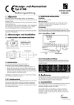
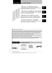
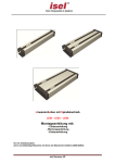
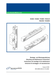
Lineareinheit GSF 8 40 R10 Anwendungs- und Montagehinweise Inhalt Symbole, Sicherheit 2 Allgemeiner Gefahrenhinweis 2 Bestimmungsgemäße Verwendung 3 Nicht bestimmungsgemäße Verwendung 3 Betriebsparameter4 Montage5 Anschluss des Antriebssatzes GSF 8 40 R10 8 Wartung9 Symbole, Sicherheit Bedeutung: Achtung, Sicherheitshinweis, Empfehlung Wartung Allgemeiner Gefahrenhinweis Die Daten und Angaben der Montageanleitung dienen allein der Produktbeschreibung und dem Zusammenbau. Die Angaben entbinden den Anwender nicht von eigenen Beurteilungen und Prüfungen. Es ist zu beachten, dass unsere Produkte einem natürlichen Verschleiß- und Alterungsprozess unterliegen. Diese Anleitung enthält wichtige Informationen, um das Produkt sicher und sachgerecht zu verwenden. Bei Verkauf, Verleih oder sonstiger Weitergabe des Produkts muss die Montageanleitung mitgegeben werden. Bei der Montage, Bedienung und Wartung der Lineareinheit GSF 8 40 R10 ist sicherzustellen, dass alle beweglichen Elemente gegen versehentliches Einschalten und Bewegen gesichert sind. Durch rotierende und bewegliche Teile können Sie sich schwer verletzen! Lesen und befolgen Sie daher unbedingt nachstehende Sicherheitshinweise. ▪Alle ▪ Arbeiten mit und an der Lineareinheit GSF 8 40 R10 sind unter dem Aspekt „Sicherheit zuerst“ durchzuführen. ▪Schalten ▪ Sie das Antriebsaggregat ab, bevor Sie Arbeiten an der Lineareinheit GSF 8 40 R10 durchführen. ▪Sichern ▪ Sie das Antriebsaggregat gegen unbeabsichtigtes Einschalten, z. B. durch das Anbringen von Hinweisschildern an der Einschaltstelle, oder entfernen Sie die Sicherung der Stromversorgung. 2 Sie nicht in den Arbeitsbereich der bewegten Bauteile der Linearein▪Greifen ▪ heit GSF 8 40 R10, wenn diese noch in Betrieb ist. ▪Sichern ▪ Sie die bewegten Bauteile der Lineareinheit GSF 8 40 R10 vor versehentlichem Berühren durch Anbringen von Schutzvorrichtungen und Abdeckungen. ▪Beachten ▪ Sie die gültigen Vorschriften zur Unfallverhütung und zum Umweltschutz im Verwenderland und am Arbeitsplatz. ▪Verwenden ▪ Sie item-Produkte nur in technisch einwandfreiem Zustand. ▪Bei ▪ Nichtverwendung von Originalersatzteilen erlischt der Gewährleistungsanspruch! ▪Prüfen ▪ Sie das Produkt auf offensichtliche Mängel. ▪Verwenden ▪ Sie das Produkt ausschließlich im Leistungsbereich, der in den technischen Daten beschrieben ist. ▪Stellen ▪ Sie sicher, dass alle zum Produkt gehörenden Sicherheitseinrichtungen vorhanden, ordnungsgemäß installiert und voll funktionsfähig sind. ▪Sie ▪ dürfen Sicherheitseinrichtungen nicht in ihrer Position verändern, umgehen oder unwirksam machen. Die hier dokumentierte Lineareinheit GSF 8 40 R10 entspricht dem Stand der Technik und berücksichtigt die allgemeinen Grundsätze der Sicherheit zum Zeitpunkt der Drucklegung dieser Montageanleitung. Trotzdem besteht die Gefahr von Personen- und Sachschäden, wenn Sie die grundsätzlichen Sicherheitshinweise und Warnhinweise in dieser Montageanleitung nicht beachten. Für daraus entstehende Schäden übernehmen wir keine Haftung. Im Interesse der Weiterentwicklung behalten wir uns das Recht auf technische Änderung vor. Bewahren Sie die Anleitung so auf, dass sie jederzeit für alle Benutzer zugänglich ist. Beachten Sie die übergeordnete Betriebsanleitung der vollständigen Maschine oder Anlage. Die allgemeinen Gefahrenhinweise beziehen sich auf den gesamten Lebenszyklus der unvollständigen Maschine. 1. Beim Transport Beachten Sie die Transporthinweise auf der Verpackung. Lagern Sie das Produkt bis zur Montage in der Originalverpackung und schützen Sie es vor Feuchtigkeit und Beschädigungen. Beachten Sie, dass bewegliche Teile beim Transport festgesetzt sind und keine Schäden verursachen können. 2. Bei der Montage Schalten Sie immer den relevanten Anlagenteil antriebslos und spannungsfrei, bevor Sie das Produkt montieren bzw. den Stecker anschließen oder ziehen. Sichern Sie die Anlage gegen Wiedereinschalten. Verlegen Sie die Kabel und Leitungen so, dass diese nicht beschädigt werden und niemand darüber stolpern kann. Vermeiden Sie Ausrutsch-, Stolper- und Sturzstellen. 4. Während des Betriebs Erlauben Sie den Zutritt zum unmittelbaren Betriebsbereich der Anlage nur Personen, die vom Betreiber autorisiert sind. Dies gilt auch während des Stillstands der Anlage. Bewegliche Teile dürfen nicht unbeabsichtigt in Gang gesetzt werden. Schalten Sie im Notfall, Fehlerfall oder bei sonstigen Unregelmäßigkeiten die Anlage ab und sichern Sie sie gegen Wiedereinschalten. Verhindern Sie die Möglichkeit des Einschließens von Personen im Gefahrenbereich der Anlage. 5. Bei der Reinigung Verschließen Sie alle Öffnungen mit geeigneten Schutzeinrichtungen, damit kein Reinigungsmittel ins System eindringen kann. Verwenden Sie keine aggressive Reinigungssubstanzen. Verwenden Sie zur Reinigung keine Hochdruckreiniger. 6. Bei der Instandhaltung und Instandsetzung Führen Sie die vorgeschriebenen Wartungsarbeiten in den zeitlichen Intervallen durch, die in der Bedienungsanleitung beschrieben sind. Stellen Sie sicher, dass keine Leitungsverbindungen, Anschlüsse und Bauteile gelöst werden, solange die Anlage unter Druck und Spannung steht. Sichern Sie die Anlage gegen Wiedereinschalten. 7. Bei der Entsorgung Entsorgen Sie das Produkt nach den nationalen und internationalen Bestimmungen Ihres Landes. 3. Bei der Inbetriebnahme Lassen Sie das Produkt vor der Inbetriebnahme einige Stunden akklimatisieren. Stellen Sie sicher, dass die unvollständige Maschine fest und sicher in die vollständige Maschine eingebunden ist. Nehmen Sie nur ein vollständig installiertes Produkt in Betrieb. Bestimmungsgemäße Verwendung Die Lineareinheit GSF 8 40 R10 ist im Sinne der Maschinenrichtlinie 2006/42/ EG eine unvollständige Maschine. Die Lineareinheit GSF 8 40 R10 darf nur den technischen Daten und den Sicherheitsvorgaben dieser Dokumentation entsprechend eingesetzt werden. Die innerbetrieblichen Vorschriften und die Richtlinien des Anwenderlandes müssen eingehalten werden. Eigenmächtige bauliche Veränderungen an der Lineareinheit GSF 8 40 R10 sind nicht zulässig. Für daraus entstehende Schäden übernehmen wir keine Haftung. Sie dürfen die Lineareinheit GSF 8 40 R10 nur dann montieren, bedienen und warten, wenn: ▪Sie ▪ fachlich ausgebildet sind, ▪Sie ▪ von Ihrem Unternehmen hierzu autorisiert sind, ▪Sie ▪ ausschließlich das Original-Zubehör des Herstellers verwenden. Bei nicht sicherem und unsachgemäßen Betrieb der Lineareinheit GSF 8 40 R10 besteht die Gefahr von erheblichen Verletzungen durch Quetsch- und Scherstellen. ▪Die ▪ Lineareinheit GSF 8 40 R10 verwendungsgerecht und sicherheitsgerecht in die vollständige Maschine integriert wurde, ▪Sie ▪ die Montageanleitung sorgfältig gelesen und verstanden haben, Nicht bestimmungsgemäße Verwendung Als nicht bestimmungsgemäße Verwendung gilt, wenn Sie das Produkt anders verwenden als es in der Montageanleitung und der bestimmungsgemäßen Verwendung autorisiert ist. Für daraus entstehende Schäden übernehmen wir keine Haftung. 3 Betriebsparameter Die Lineareinheit GSF 8 40 R10 wird generell aus Baugruppen und auf Maß zugesägten Profilen der Baureihe 8 gefertigt und ist vor der eigentlichen Montage auf Vollständigkeit zu überprüfen. Zubehör: 0.0.654.21 0.0.654.22 0.0.654.23 0.0.654.24 Zahnriemenantrieb GSF 8 40 R10 Zahnriemenumlenkung GSF 8 40 R10 Antriebssatz GSF 8 40 Schlittensatz GSF 8 80x40 Der Sicherheitsweg S ist ein Wegausgleich für Toleranzen und das Überschwingen des Schlittens bei hohen Belastungen und Beschleunigungen im Umkehrpunkt. In Abhängigkeit von den Möglichkeiten des Antriebs und der Steuerung ist der Sicherheitsweg zu berücksichtigen, er sollte jedoch in keinem Fall kleiner als 27,5 mm sein! Lineareinheit GSF 8 40 R10 S 5 H +24 +H 2xS L= 85 80 52 S Lmin = 300 mm smin = 27,5 mm Hmax = 3860 mm m1 = 1,3 kg m2 = 1,85 g/mm Wiederholgenauigkeit = ±0,5 mm Montageanleitung 1 Satz 40 0.0.655.98 80 Parameter, Geometrie 1 2 3 4 5 6 7 1 Zahnriemenantrieb GSF 8 40 R10 2 Profil X 8 40x40 1N 3 Zahnriemen R10 T5 4 Schlittenplatte* 5 Gleitschuh* 6 Gleitschlitten* 7 Zahnriemenumlenkung GSF 8 40 R10 l *(4, 5, 6 = Schlittensatz GSF 8 80x40) Riemenlänge L= 2 x l + 210 mm 5 T5,DIN7721 4 Zahnriemen R10 T5 10 mit integrierten Stahllitzen zul. Belastung 300 N K = 75 N m = 23 g/m schwarz, Zuschnitt max. 50 m 0.0.400.04 schwarz, 1 Rolle à 50 m 0.0.400.11 Auslegung Vereinfachtes Verfahren zur Bestimmung der maximal zulässigen Belastung der Gleitschlittenführung GSF: x GSF y z Mz Fx Mx Mx max [Nm] My max [Nm] Mz max [Nm] Fy max [N] Fz max [N] 0,4 2 1,25 25 50 Für kombinierte Lasten gilt: |My| |Mz| |Fy| |Fz| |Mx| ____ ____ ___ ___ ____ + Mx max My max + Mz max + Fy max + Fz max ≤ 1 Fz My Fy Laufstrecke bei max. Belastung: 1000 km Max. Geschwindigkeit: 1 m/s Beschreibung Zahnriementrieb: Aufstellung und Betrieb nicht in der Nähe von Sand- oder Staubquellen. Wälzgelagerte Zahnriemenscheibe r = 18,3 mm Wirkradius: p = 5 mm Zahnteilung: z = 23 Zähnezahl: MA = 3 Nm Max. Antriebsleistung Reibmoment bei Leerfahrt: MR = 0,1 Nm Aufstellung und Betrieb nicht in Bereichen, in denen regelmäßig Stöße mit hohem Energieinhalt auftreten, hervorgerufen z. B. von Pressen oder Schwermaschinen. Umgebungsbedingungen: Lagertemperatur Relative Luftfeuchtigkeit –20 °C bis +70 °C 5 % bis 85 % Lineareinheit GSF 8 40 R10 ist vorgesehen für den ortsfesten Einsatz in wettergeschützten Bereichen. Kein Auftreten von Schimmelwachstum und Schwamm sowie keine Nagetiere oder andere tierische Schädlinge. Aufstellung und Betrieb nicht in unmittelbarer Nachbarschaft von industriellen Anlagen mit chemischen Emissionen. Bei Zweifel an der Beständigkeit gegen bestimmte Chemikalien, z.B. bei Prüföl, legierten Ölen, aggressiven Waschsubstanzen, Lösungsmitteln oder bei Bremsflüssigkeit empfehlen wir die Rücksprache mit Ihrer Fachvertretung. Bei Betrieb in stark salzhaltiger Luft, Rücksprache mit dem Hersteller halten. Die Durchbiegung der Linearachse GSF 8 40 R sollte unter 1 mm auf 1000 mm Achse liegen. Bei hohen Anforderungen an die Systemdynamik sollte alle 300 mm bis 600 mm unterstützt werden. Die Unterstützung darf nicht auf die Umlenkungen wirken. Bei nachträglichem Anbau an einen bestehenden Rahmen muss unter Umständen eine Freimachung für den Riemen eingebracht werden (Beispiel Schiebetür) Montage 1. Profilbearbeitungen: Ablängen des Profils der Baureihe 8. Profillänge:LProfil = 2xS+H+85 mm S = Sicherheitszone = 27,5 mm H = Hub An beiden Enden des Profils der Baureihe 8 wird in die Kernbohrung ein Gewinde geschnitten: M8x25 5 2. Vorbereitung Schlittensatz GSF 8 80x40: 85 8 6 Einlegen und eindrücken der 3 Sechskantmuttern ISO 4035-M6 in den Werkzeugschlitten. 24 M5 Um die notwendige Klemmwirkung des Zahnriemens zwischen Schlitten12 platte und dem Gleitkörper zu erzeugen genügen die äußeren Schrauben. Die Sechskantmuttern ISO 4035-M6 dienen der Befestigung der Schlittenplatte. Wird eine der Verschraubungen nicht genutzt, darf die entsprechend Sechskantmutter nicht eingelegt werden, da sie während des Betriebes in die Laufbahn des Schlittens fallen kann und zu Beschädigungen führt. 8 Anschließend wird der Schlittensatz GSF 8 80x40 in die offene Nut des Profils der Baureihe 8 eingeschoben. Sie Schlittenplatte ist noch nicht montiert. 3. Befestigung der Haltelasche: Die Haltelasche der Zahnriemenumlenkung GSF 8 40 R10 und die Haltelasche des Zahnriemenantriebs GSF 8 40 R10 wird jeweils mit einer Halbrundschraube ISO 7380-M8x18 befestigt. Anzugsmoment M8x25: 25 Nm. 4. Einschub des Zahnriemens: 38 35.6 0.7 12 Der Zahnriemen wird nun auf die berechnete Länge zugeschnitten und anschließend in die Nut oder den Hohlraum des Profils der Baureihe 8 eingeschoben. Wir empfehlen den Zahnriemen immer etwas länger zu lassen als berechnet um Korrekturen vornehmen zu können. Zahnriemenlänge: LR = 2xLProfil+210 mm □40 Beispiel, Profil X 8 40x40 5. Befestigung der Zahnriemenumlenkung und des Zahnriemenantriebs: Ist der Zahnriemen durch die untere Nut des Profils geführt wird er in den Zahnriemenantrieb und die Zahnriemenumlenkung eingefädelt. Das Umlenkungsgehäuse oder das Antriebgehäuse werden anschließend mit jeweils 2 Zylinderschrauben DIN 6912-M4x6 an der Haltelasche befestigt. Anzugsmoment: M = 3 Nm 6 38 6. Befestigung der Zahnriemens am Schlittensatz GSF 8 80x40: Der Zahnriemen wird in die Zahnprofilierung des Schlittensatz GSF 8 80x40 eingelegt. Dabei sollen alle Zähne im Eingriff sein. Anschließend wird mit Hilfe der Deckplatte, der zuvor eingelegten Muttern M6 und der Zylinderkopfschrauben DIN 6912-M6x20 der Zahnriemen geklemmt. Dazu ist die Verwendung der beiden äußeren Schrauben Minimalvoraussetzung. Wird eine der Verschraubungen nicht genutzt, darf die entsprechend Sechskantmutter nicht eingelegt werden, da sie während des Betriebes in die Laufbahn des Schlittens fallen kann und zu Beschädigungen führt. 10 17 53 13 17 7. Berechnen und Einstellen der Zahnriemenspannung: Falls die GSF 8 80x40 komplett vormontiert geliefert wird, muss die Vorspannung eingestellt werden oder entsprechend den Bestellvorgaben geprüft werden. Beim Spannen wird zunächst der Nullpunkt gesucht, an dem der ungespannte Zahnriemen vollständig ohne Durchhang anliegt und die Vorspannung beginnt. Dazu wird die bewegliche Spannachse in der Zahnriemenumlenkung mit der Hilfe der Rückseitigen Spannschraube zurückgezogen. Der erforderliche Spannweg an der Umlenkung wird in Abhängigkeit von der Betriebslast der GSF ermittelt. Herkömmliche Berechnung: Es gilt: FRV + Fx < FRzul L . F V ΔL = ______ und:FRV > Fx 1000 . K mit:Fx = m x a+ m x g +FR ∆L = 2 x Spannweg [mm] mit: LR = gesamte Zahnriemenlänge [mm] FRV = Vorspannkraft Zahnriemen [N] FRzul =zulässige Zahnriemenkraft [N] Fx = Betriebslast [N] FR = Reibkraft, Reibverlust bei Leerfahrt [N] = 5,5 N K = Dehnungskonstante [N] Die bewegliche Spannachse in der Zahnriemenumlenkung wird mit Hilfe der Spannschraube bewegt. Dadurch wird der Zahnriemen gespannt oder entspannt, 1mm Weg der Spannachse entspricht 2mm Spannen des Zahnriemens. Der ermittelte Spannweg kann mit Hilfe unterschiedlicher Hilfsmittel kontrolliert werden. Typische Kontrollinstrumente sind Frequenzanalysegeräte, Dehnungsmessstreifen und andere Längenmessgeräte. Tipp: Mit Hilfe von Markierungen und einem Stahllineal kann die Einstellung der Vorspannung kontrolliert werden. 7 Anschluss des Antriebssatzes GSF 8 40 R10 Nach Vorgaben des verwendeten Motors oder eines Getriebes wird das Antriebsgehäuse oder die Adapterplatte bearbeitet und mit dem Motor bzw. Getriebe verschraubt. Die mit der Antriebswelle zu verbindende Kupplungshälfte wird auf das Maß der Antriebswelle aufgebohrt und mit der Welle verbunden. Die übertragenen Drehmomente der Spannverbindung berücksichtigen das maximale Passungsspiel bei Wellenpassungen: Welle k6 / Bohrung H7 Die Kraftübertragung der Kupplung zur Antriebswelle erfolgt reibschlüssig. Zur reibschlüssigen Verbindung der Antriebswelle muss die Bohrung der Kupplungsnabe und die Welle entfettet und gereinigt werden. Erfordert die Antriebswelle eine formschlüssige Verbindung zur Kupplungshälfte, so muss diese nach Herstellerangaben des Motors oder des Getriebe bearbeitet werden. Verwendete Zylinderschrauben sind gegen Selbstlockern zu sichern. 52 ⌀34 10 2 □66 ⌀20 ⌀3 5 66 55 □6 6 34 10 22 26.5 Anschlussgeometrie: Klemmverbindung der Motorwelle zur Kupplung: Minimale Einstecktiefe der Antriebswelle: 22 mm Maximale Einstecktiefe der Antriebswelle: 26,5 mm Klemmschraube:M3 1,5 Nm Anzugsmoment: Bohrungsdurchmesser D[mm] der Motorwelle:D6-D16 3 Nm Übertragbares Antriebsmoment MA: Kupplungshälfte zum Anschluss an die Antriebsumlenkung 52 ⌀34 2 Zu bearbeitende Kupplungshälfte zum Anschluss einer Antriebswelle ⌀20 ⌀3 55 □6 6 5 66 34 10 Die weitere Montagereihenfolge ist von den Gegebenheiten abhängig. Wir empfehlen die gesamte Kupplung auf die Antriebswelle zu stecken, den Motor auf die bearbeitete Flanschplatte oder dem bearbeiteten Kupplungsgehäuse zu befestigen und anschließend auf die Welle der Antriebsumlenkung der GSF 8 40 R10 zu schieben. Durch die Bohrungen im Kupplungsgehäuse des 8 ⌀20 ⌀34 Der Antriebssatz GSF 8 40 dient zum Anschluss beliebiger Antriebe an die Lineareinheit GSF 8. Die flexible Kupplung kann auf viele Antriebswellen angepasst werden und überträgt das Antriebsmoment spielfrei. Dazu werden die Zylinderschrauben DIN7984 M4x45, liegen dem Antriebssatz bei, durch das Gehäuse des Zahnriemenantriebs in das Kupplungsgehäuse des Antriebssatzes geschraubt. Anzugsmoment: M = 3 Nm Zu bearbeitendes Antriebsgehäuse zum Anschluss eines Getriebes, Motors Zu bearbeitende Anschlussplatte zum Anschluss eines Getriebes, Motors Antriebsatzes GSF 8 40 wird, mit Hilfe eines Innensechskantschlüssels SW2,5, die notwendige Klemmkraft zwischen Kupplung und Antriebswellen erzeugt. Anschließend den Zugriff auf die rotierende Kupplung mit Hilfe der Abdeckkappen verschließen. Wartung Die Lineareinheit GSF 8 40 R10 ist wartungsfrei. Der Kunststoff im Schlitten ist für das Gleiten optimiert. Unter Beachtung der vorgegebenen Belastungen bleibt der Schlitten unterhalb der tolerierten Verschleißgrenze, bei einer Laufstrecke von 1000 km, danach muß der Schlitten ersetzt werden. Der Verschleiß im Betrieb hängt maßgeblich von den Einsatzbedingungen ab und sollte ständig kontrolliert werden. Ideale Betriebsbedingungen: Der Zahnriemen sollte alle 250 km inspiziert werden und bei sichtbaren Beschädigungen, Abrieb oder außergewöhnlichen Laufgeräuschen ausgetauscht werden. Umgebungstemperatur: 10°C ... 40°C Belastung: < 5% Verfahrgeschwindigkeit: < 1 m/s 9 0.4.122.1704/2014 Telefon +49 212 6580 0 Telefax +49 212 6580 310 [email protected] www.item24.com Den Anwendungs- und Montagehinweis finden Sie im Internet im Downloadbereich des Produktes. © item Industrietechnik GmbH Made in Germany item Industrietechnik GmbH Friedenstraße 107-109 42699 Solingen Deutschland Linear Unit GSF 8 40 R10 Notes on Use and Installation Contents Symbols, safety 2 General safety information 2 Correct use 3 Improper use 3 Operating parameters 4 Assembly5 Connecting the Drive Set GSF 8 40 R10 8 Maintenance9 Symbols, safety Important, safety information, recommendation Maintenance General safety information The details and information in the installation guide are provided for the purposes of describing the product and its assembly only. The information does not discharge the user from the obligation to carry out his own assessments and checks. It is important to bear in mind that our products are subject to a natural process of wear and ageing. These notes contain important information that will enable you to use the product safely and appropriately. When sold, rented out or otherwise passed on to another party, this product must be handed over with the installation guide. ▪Do ▪ not place your hand within the operating range of moving parts in Linear Unit GSF 8 40 R10 when the unit is still switched on. When installing, operating and maintaining Linear Unit GSF 8 40 R10, it is important to ensure that all moving elements are secured so that they cannot be switched on and moved unintentionally. Rotating and moving parts can cause serious injury! You must therefore read and follow the safety instructions set out below. ▪Use ▪ only item products that are in perfect working order. ▪All ▪ work on and with Linear Unit GSF 8 40 R10 must be performed with “safety first” in mind. switch off the drive assembly before you start working on Linear Unit ▪Always ▪ GSF 8 40 R10 the drive unit cannot be switched on unintentionally, e.g. by affixing ▪Ensure ▪ warning notices at the activation point or by removing the fuse from the power supply. 2 ▪Fit ▪ guards and covers so that the moving parts of Linear Unit GSF 8 40 R10 cannot be touched unintentionally. ▪Observe ▪ the regulations pertaining to accident prevention and environmental protection that apply in the country and place of work where the product is being used. ▪Failure ▪ to use original spare parts will invalidate the product warranty! ▪Check ▪ the product for obvious defects. ▪Use ▪ the product only within the performance range described in the technical data. ▪Ensure ▪ that all the safety equipment associated with the product is present, properly installed and in full working order. ▪Do ▪ not alter the position of safety equipment, circumvent it or render it ineffective. Linear Unit GSF 8 40 R10, as described here, corresponds to the state of the art and takes into account the general principles of safety applicable at the time this installation guide was published. Nevertheless, failure to observe the safety instructions and warning notices in this installation guide may result in personal injury and damage to property. We will assume no liability for any resulting damage or injury. We reserve the right to make technical changes that represent technical advances. Keep these installation notes in a place where they can be easily accessed by all users. Observe the directions contained in the main user guide for the completed machine. The general safety information applies to the entire lifecycle of the partly completed machine. 1. During transportation Observe the handling instructions on the packaging. Until it is installed, the product must be stored in its original packaging, protected from moisture and damage. Ensure that moving parts are secured when in transit and cannot cause any damage. 2. During installation Always deactivate the power to the relevant system part and ensure it is not live before installing the product and/or plugging it in or unplugging it. Ensure the system cannot be switched back on. Lay cables and lines in such a way that they cannot be damaged and do not represent a trip hazard. Avoid areas that pose slip, trip and fall hazards. 4. During operation Ensure that only persons who have been authorised by the operator have access to the immediate operating environment of the system. This also applies when the system is not in operation. It must not be possible to actuate moving parts unintentionally. During emergencies, malfunctions or other irregularities, deactivate the system and ensure that it cannot be switched back on. Prevent the possibility of persons becoming trapped in the system’s hazard zone. 5. During cleaning Close all openings with suitable protective equipment to ensure that cleaning agents cannot penetrate the system. Do not use aggressive cleaning substances. Do not use a high-pressure cleaner when cleaning the system. 6. During maintenance and servicing work Carry out the prescribed maintenance work at the intervals stipulated in the user guide. Ensure that no line links, connections or components are removed while the system is live and under pressure. Ensure the system cannot be switched back on. 7. During disposal Dispose of the product in accordance with the national and international regulations that apply in your country. 3. During start-up Allow the product to acclimatise for a few hours before starting it up. Ensure that the partly completed machine is securely and safely integrated into the completed machine. Only start up a product that has been installed in full. Correct use Linear Unit GSF 8 40 R10 is a partly completed machine as defined in the Machinery Directive (2006/42/EC). Linear Unit GSF 8 40 R10 must only be used in accordance with the technical data and safety requirements set out in this document. Internal company requirements and the regulations that apply in the country where the product is being used must be observed. You must not make any design modifications to Linear Unit KRF GSF 8 40 R10 yourself. We will assume no liability for any resulting damage or injury. You may only install, operate and maintain Linear Unit GSF 8 40 R10 if: ▪You ▪ are authorised to do so by your company, ▪You ▪ are using only original equipment from the manufacturer. Unsafe or inappropriate use of Linear Unit GSF 8 40 R10 runs a risk of serious injury through crushing and cuts. ▪Linear ▪ Unit GSF 8 40 R10 has been integrated properly and safely into the completed machine, ▪You ▪ have carefully read and understood the installation guide, ▪You ▪ are appropriately qualified, Improper use Improper use is defined as any use of the product for purposes other than those authorised in the installation guide and under the definition of correct use. We will assume no liability for any resulting damage or injury. 3 Operating parameters Linear Unit GSF 8 40 R10 is constructed from Line 8 profiles that have been cut to size and various assemblies. Before starting assembly work, it is important to check that all parts are present. The safety distance S is a reserve distance to accommodate tolerances and slide overtravel under high loads and accelerations at the reversal point. It must be factored into the equation depending on the capabilities of the drive and control system, but in any event should not be smaller than 27.5 mm! Accessories: 0.0.654.21 0.0.654.22 0.0.654.23 0.0.654.24 Timing-Belt Reverse Unit GSF 8 40 R10 Timing-Belt Reverse Unit GSF 8 40 R10 Drive Set GSF 8 40 Slide Set GSF 8 80x40 Linear Unit GSF 8 40 R10 S 5 H +24 +H 2xS L= 85 80 52 S Lmin = 300 mm smin = 27.5 mm Hmax = 3860 mm m1 = 1.3 kg m2 = 1.85 g/mm Repeat accuracy = ±0.5 mm Installation guide 1 set 40 0.0.655.98 80 Parameters, geometry 1 2 3 4 5 6 7 1 Drive Unit GSF 8 40 R10 2 Profile X 8 40x40 1N 3 Timing Belt R10 T5 4 Slide plate* 5 Sliding shoe* 6 Slide* 7 Timing-Belt Reverse Unit GSF 8 40 R10 l *(4, 5, 6 = Slide Set GSF 8 80x40) Belt length L= 2 x l + 210 mm 5 T5,DIN7721 4 Timing Belt R10 T5 10 With integrated steel wires Perm. load 300 N K = 75 N m = 23 g/m black, cut-off max. 50 m 0.0.400.04 black, 1 roll length 50 m 0.0.400.11 Design Simplified method for determining the maximum permissible load for the T-Slot Slider of a GSF: x GSF y z Mz Fx Mx Mx max [Nm] My max [Nm] Mz max [Nm] Fy max [N] Fz max [N] 0.4 2 1.25 25 50 The following applies forcombined loads: |My| |Mz| |Fy| |Fz| |Mx| ____ ____ ___ ___ ____ + Mx max My max + Mz max + Fy max + Fz max ≤ 1 Fz My Fy Run length under max. load: 1000 km Max. Speed: 1 m/s Description of timing-belt drive: Do not install or use near sources of sand or dust. Ball-bearing mounted timing pulley r = 18.3 mm Effective radius: p = 5 mm Pitch: z = 23 Number of teeth: MA = 3 Nm Max. drive power Do not install or use in an area that is regularly exposed to high-energy surges such as those caused by presses or heavy machinery, for example. Frictional moment when running light: MR = 0.1 NmAmbient conditions: –20 °C to +70 °C Storage temperature 5 % to 85 % Relative humidity Consult the manufacturer if using in very salty air. Linear Unit GSF 8 40 R10 is intended as a permanent fixture to be used in an area that is protected from the weather. The area should be free from mould and fungus and show no traces of rodents or other pests. In case of doubt regarding resistance to certain chemicals such as test oil, alloyed oils, aggressive cleaning substances, solvents or brake fluid, we advise that you consult your specialist representative. Deflection in the linear axis of the GSF 8 40 R should not exceed 1 mm over an axis of 1000 mm. In scenarios where high demands are placed on the system dynamics, supports should be added every 300 mm to 600 mm. These supports must not affect the Reverse Units. When retrofitting to an existing frame, it may be necessary to machine an opening for the belt under certain circumstances (e.g. sliding door) Do not install or use in close proximity to industrial plants that produce chemical emissions. Assembly 1. Profile machining: Cut the Line 8 profile to size. Profile length: Lprofile = 2xS+H+245 mm S = safety zone = 27.5 mm H = stroke Tap a thread into the core bore at both ends of the Line 8 profile: M8x25 5 2. Preparing Slide Set GSF 8 80x40: 85 8 6 Press the 3 hexagon nuts ISO 4035-M6 into the slide. The outer screws are sufficient to ensure the Timing Belt is clamped in place between the carriage plate and the slide. The hexagon nuts ISO 4035M6 are used to fasten the carriage plate. 12 8 Next, slot Slide Set GSF 8 80x40 into the open groove of the Line 8 profile. The carriage plate has not been fitted at this point. 3. Fitting the retaining bracket: Use one Button-Head Screw ISO 7380-M8x18 each to install the retaining bracket for Timing-Belt Reverse Unit GSF 8 40 R10 and Drive Unit GSF 8 40 R10. Tightening torque M8x25: 25 Nm. 4. Inserting the Timing Belt: 38 35.6 0.7 12 First cut the Timing Belt to the calculated length then insert it into the Timing Belt length: LB = 2xLProfile+210 mm □40 Example: Profile X 8 40x40 5. Fastening the Timing-Belt Reverse Unit and the Drive Unit: After pushing the Timing Belt through the lower groove of the profile, feed it into the Drive Unit and the Timing-Belt Reverse Unit. Next, use 2 Hexagon Socket Head Cap Screws DIN 6912-M4x6 each to fasten the Reverse Unit and Drive Unit housings to the retaining bracket. Tightening torque: M = 3 Nm 6 38 M5 If one of the screw connections is not to be used, you must leave out the corresponding hexagon nut, as it could otherwise fall into the slide track during operation and cause damage. groove or cavity of the Line 8 profile. We recommend leaving the Timing Belt a little longer than the calculated length to allow for corrections. 24 6. Fastening the Timing Belt to Slide Set GSF 8 80x40: Fit the Timing Belt onto the teeth on Slide Set GSF 8 80x40. Make sure you mesh all the teeth. Next, use the cover plate, the M6 nuts that were inserted previously and the Hexagon Socket Head Cap Screws DIN 6912-M6x20 to clamp the Timing Belt in place. To do this, you must use at least the two outer screws. If one of the screw connections is not to be used, you must leave out the corresponding hexagon nut, as it could otherwise fall into the slide track during operation and cause damage. 53 10 17 13 17 7. Calculating and setting the Timing-Belt tension: If the GSF 8 80x40 has been supplied fully preassembled, you will need to adjust the pre-tensioning or check it against the order specifications. The first step when tightening the Timing Belt is to find the zero point at which the untightened belt has no sag at all and pre-tensioning begins. To do this, use the tensioning screw at the rear of the Timing-Belt Reverse Unit to pull back the movable tensioning axle. The tensioning axle setting required on the Reverse Unit varies according to the operating load of the GSF. Conventional calculation: The following applies: FBP + Fx < FBperm and:FBP > Fx where:Fx = m x a+ m x g +FF L . FV ΔL = ______ where: ∆L = 2 x tensioning axle setting [mm] 1000 . K LB = total length of Timing Belt [mm] FBP = pretensioning on Timing Belt [N] FBperm = permissible force for Timing Belt [N] Fx = operating load [N] FF = frictional force, loss of friction when running light [N] = 5.5 N K = constant of expansion [N] Use the tensioning screw to adjust the movable tensioning axle in the TimingBelt Reverse Unit. Moving the axle makes the Timing Belt tighter or slacker, adjusting the tensioning axle setting by 1 mm adjusts the Timing Belt by 2 mm. The calculated tensioning axle setting can be checked by various means. Typical tools include frequency analysis tools, strain gauges and other length measuring devices. Tip: You can use markings and a steel ruler to check pre-tensioning. 7 Connecting the Drive Set GSF 8 40 R10 Machine the drive casing or Adapter Plate according to the requirements of the motor or gearbox you are using and then screw it to the motor or gearbox. Take the Coupling Half that is to be connected to the drive shaft and drill a hole in it to match the drive shaft then connect the Coupling Half and the shaft. The torques transferred by the clamp connection factor in the maximum mating play for shaft fits: Shaft k6 / hole H7 Force is transferred from the coupling to the drive shaft by means of frictional resistance. The Shaft and the hole in the coupling hub must be degreased and cleaned to ensure the frictional resistance is effective. If the drive shaft requires a rigid connection to the Coupling Half, this must be machined in accordance with specifications of the motor or gearbox manufacturer. Hexagon Socket Head Cap Screws must be secured against working loose. 52 ⌀34 10 2 □66 ⌀20 ⌀3 5 66 55 □6 6 34 10 22 26.5 Connection geometry: Clamping connection between motor shaft and coupling: Minimum insertion depth for the drive shaft: 22 mm Maximum insertion depth for the drive shaft: 26,5 mm Clamping screw: M3 Tightening torque: 1.5 Nm Bore diameter D[mm] of the motor shaft:D6-D16 3 Nm Transferable torque MA: Coupling Half to be connected to the drive Reverse Unit 52 ⌀34 2 Coupling Half to be machined, for connecting a drive shaft ⌀20 ⌀3 55 □6 6 5 66 34 10 The subsequent installation sequence varies according to the circumstances. We advise first slotting the entire coupling onto the drive shaft and fastening the motor to the prepared flange plate or Coupling Housing. Once this has been done, slot the coupling onto the shaft of the GSF 8 40 R10 Reverse Unit. Use a 2.5 A/F Allan key inserted through the holes in the Coupling Housing of the 8 ⌀20 ⌀34 Drive Set GSF 8 40 can be used to connect any drives to Linear Unit GSF 8. The versatile coupling can be adapted for several different drive shafts and transfers drive torque without play. Hexagon Socket Head Cap Screws DIN 7984 M4x45 are supplied with the Drive Set for this purpose and are screwed through the housing of the Drive Unit and into the Coupling Housing of the Drive Set. Tightening torque: M = 3 Nm Drive casing to be machined, for connecting a gearbox or motor Connecting Plate to be machined, for connecting a gearbox or motor Drive Set GSF 8 40 to set the necessary clamping force between the coupling and drive shafts. Next, use the caps to cover over the access points to the rotating coupling. Maintenance Linear Unit GSF 8 40 R10 requires no maintenance. The plastic in the slide has been optimised for gliding. If the load specifications are observed, the slide will stay within tolerable wear limits for a service life of 1000 km, after which point it will need to be replaced. The degree of wear that occurs during operation depends largely on the conditions of use and should be checked at regular intervals. Ideal operating conditions: The Timing Belt should be inspected every 250 km and replaced if any visible damage, wear or unusual travel noises are observed. Ambient temperature: 10°C ... 40°C Load: < 5% Stroke velocity: < 1 m/s 9 0.4.122.1704/2014 Phone +49 212 6580 0 Fax +49 212 6580 310 [email protected] www.item24.com You find the Notes on Use and Installation online, in the download section for this product. © item Industrietechnik GmbH Made in Germany item Industrietechnik GmbH Friedenstrasse 107-109 42699 Solingen Germany