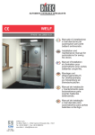
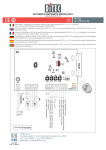
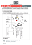
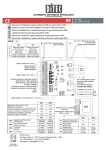
Download WELF

Transcript
WELF
IP1819 - rev. 2008-03-13
I
GB
DITEC S.p.A.
Via Mons. Banfi, 3 - 21042 Caronno Pertusella (VA) - ITALY
Tel. +39 02 963911 - Fax +39 02 9650314
www.ditec.it - [email protected]
Manuale di installazione
e manutenzione per
automazioni per porte
battenti antincendio.
Installation and
maintenance manual for
automations for swing
fire doors.
F
Manuel d'installation
et d'entretien pour
automatisme pour portes
battantes coupe-feu.
D
Montage und
Wartungshandbuch
für Drehtürantriebe
zur Anwendung an
Brandschutztüren.
4
3x
1.5
mm
2
4x
²
0.5
1
mm
²
3
Fig. 1
13
13
7
14
5
11
12
8
9
15
6
9
10
WELF - IP1819
2
Fig. 2
FA (1-S2) = Endschalter öffnen
Open limit switch
FA (1-S1) = Ausschalten Sicherheitsvorrichtung (1-6)
Safety stop (1-6) disabled
Schließgeschwindigkeit
Closing speed
Bremsgeschwindigkeit
Proximity speed
FC ~20°
BRAKE
PROXIMITY SPEED CLOSING SPEED
RELEASE
0-1 INPUT
NO C NC -MOT+ -MOT+
RELEASE
LO HI
LO ME HI HI-ADJ
FC = Vorendschalter Schließen
Close proximity switch
RESET
NC
NO
Motor
24 V=
J2
-MOT+
J1
POWER
ALARM
ENC
OPEN
SA
DIR
VC
1 S1 S2
IN
J3
VA
RF
COM
TC
C
-LK+
99
NICHT VERWENDEN
DO NOT USE
POWER
Ausgang Elektroschloss Lock output +
24 V= / max 1,2 A
NO
FA = Endschalter öffnen, oder
Ausschalten der
Sicherheitsvorrichtung (1-6)
FA = Open limit switch, or
safety stop (1-6) disabled
BAT
0 1 21 22
Automatisches Schließen / Automatic closure
Öffnung Seite A / Side A opening
Öffnung Seite B / Side B opening
Schließen / Closing
Anhaltesicherheit / Safety stop
Umkehrsicherheit / Safety reversal
Stop
Reset
ON
0 1 1 2 3A 3B 4 6 8 19 G1
29G2H
Ausgang / Output 24 V= / 0,5 A +
1 2 3 4 5 6
NICHT VERWENDEN
DO NOT USE
(falls vorhanden)
0 1 G1 G2 G3 41
Ausgang General Purpose
Output 24 V= / 0,1 A
C
POWER
RESET
F1
Netzsicherung / Line fuse
F1=F1,6A
AL2
L N
Reset / Manual reset
L N
L N
F2
FIRE
L N
Eingang Alarm / Alarm input
RELEASE AL-IN RESET
Manueller Schließvorgang
Closing manual release
Stromversorgung WELF 2. Flügel
Power supply WELF second wing
0 1F
Brandschutzmelder / Fire/smoke sensor
200 mA
24 V=
+
EXT LED
LED Alarm/OK
NC C NO
Ausgang Alarmkontakt (10 A - 250 V~)
Alarm output contact (10 A - 250 V~)
Sicherung/ Fuse
F2=T63mA
Stromversorgung / Power supply
230 V~ / 50-60 Hz
Erdung / Ground
Fig. 3
3
WELF - IP1819
B
A
C
90
°
MOUNTING DIMENSIONS OPERATOR WELF - SIZE EN5 AND SIZE EN6 (NMWEL04)
MONTAGEMAßE WELF ANTRIEB - TÜRGRÖßE EN5 UND TÜRGRÖßE EN6 (NMWEL04)
EN5
EN6
A (mm)
405
405
B (mm)
310
340
C (mm)
95
65
WELF - IP1819
Distance between main operator shaft and wing axis.
Abstand zwischen Hauptantriebswelle und Flügelachse.
Distance between joint arm shaft and wing axis.
Abstand zwischen Gelenkarmwelle und Flügelachse.
Distance between joint arm shaft and main operator shaft.
Abstand zwischen Gelenkarmwelle und Hauptantriebswelle.
4
FIXING POINTS WELF OPERATOR (NMWEL05)
BEFESTIGUNGSPUNKTE WELF ANTRIEB (NMWEL05)
Band
40
Antriebswelle
120
60
160
60
A
405
Bohrung Ø 6.5
M6 Schraube
340 für Grösse 6
310 für Grösse 5
80
B
120
B
40
23
170
62
Türoberkante
22
Ø 6,5
35
Bohrung Ø 7
M6 Schraube
Ø
40
23
33
63
B-B
106
15
30.5
7
30
A (1 : 5)
C
~ 400
Max 250
Minimum 5mm
Maximum 15mm
C (1 : 5)
15
5
WELF - IP1819
I
AVVERTENZE GENERALI PER LA SICUREZZA
DIRETTIVA MACCHINE
Il presente manuale di installazione è rivolto esclusivamente a personale professionalmente competente.
L’installazione, i collegamenti elettrici e le regolazioni devono
essere effettuati nell’osservanza della Buona Tecnica e in ottemperanza alle norme vigenti.
Leggere attentamente le istruzioni prima di iniziare l’installazione
del prodotto.
Una errata installazione può essere fonte di pericolo. I materiali
dell’imballaggio (plastica, polistirolo, ecc.) non vanno dispersi
nell’ambiente e non devono essere lasciati alla portata dei bambini in quanto potenziali fonti di pericolo.
Prima di iniziare l’installazione verificare l’integrità del prodotto.
Non installare il prodotto in ambiente e atmosfera esplosivi:
presenza di gas o fumi infiammabili costituiscono un grave
pericolo per la sicurezza.
Prima di installare la motorizzazione, apportare tutte le modifiche
strutturali relative alla realizzazione dei franchi di sicurezza ed
alla protezione o segregazione di tutte le zone di schiacciamento, cesoiamento, convogliamento e di pericolo in genere.
Verificare che la struttura esistente abbia i necessari requisiti di
robustezza e stabilità. Il costruttore della motorizzazione non è
responsabile dell’inosservanza della Buona Tecnica nella costruzione degli infissi da motorizzare, nonché delle deformazioni
che dovessero intervenire nell’utilizzo. I dispositivi di sicurezza
(fotocellule, coste sensibili, stop di emergenza, ecc.) devono
essere installati tenendo in considerazione: le normative e le
direttive in vigore, i criteri della Buona Tecnica, l’ambiente di
installazione, la logica di funzionamento del sistema e le forze
sviluppate dalla porta o cancello motorizzati.
I dispositivi di sicurezza devono proteggere eventuali zone di
schiacciamento, cesoiamento, convogliamento e di pericolo in
genere, della porta o cancello motorizzati.
Applicare le segnalazioni previste dalle norme vigenti per individuare le zone pericolose.
Ogni installazione deve avere visibile l’indicazione dei dati identificativi della porta o cancello motorizzati.
Prima di collegare l’alimentazione elettrica accertarsi
che i dati di targa siano rispondenti a quelli della rete di
distribuzione elettrica. Prevedere sulla rete di alimentazione un
interruttore/sezionatore onnipolare con distanza d’apertura dei
contatti uguale o superiore a 3 mm.
Verificare che a monte dell’impianto elettrico vi sia un interruttore
differenziale e una protezione di sovracorrente adeguati.
Quando richiesto, collegare la porta o cancello motorizzati ad
un efficace impianto di messa a terra eseguito come indicato
dalle vigenti norme di sicurezza.
Durante gli interventi di installazione, manutenzione e riparazione, togliere l’alimentazione prima di aprire il coperchio per
accedere alle parti elettriche.
La manipolazione delle parti elettroniche deve essere effettuata munendosi di bracciali conduttivi antistatici collegati
a terra. Il costruttore della motorizzazione declina ogni responsabilità qualora vengano installati componenti incompatibili ai
fini della sicurezza e del buon funzionamento.
Per l’eventuale riparazione o sostituzione dei prodotti dovranno
essere utilizzati esclusivamente ricambi originali.
L’installatore deve fornire tutte le informazioni relative al funzionamento automatico, manuale e di emergenza della porta o
cancello motorizzati, e consegnare all’utilizzatore dell’impianto
le istruzioni d’uso.
Ai sensi della Direttiva Macchine (98/37/CE) l’installatore che
motorizza una porta o un cancello ha gli stessi obblighi del
costruttore di una macchina e come tale deve:
- predisporre il fascicolo tecnico che dovrà contenere i documenti indicati nell’Allegato V della Direttiva Macchine;
(Il fascicolo tecnico deve essere conservato e tenuto a
disposizione delle autorità nazionali competenti per almeno
dieci anni a decorrere dalla data di costruzione della porta
motorizzata);
- redigere la dichiarazione CE di conformità secondo l’Allegato
II-A della Direttiva Macchine e consegnarla al cliente;
- apporre la marcatura CE sulla porta motorizzata ai sensi del
punto 1.7.3 dell’Allegato I della Direttiva Macchine.
Per maggiori informazioni consultare le “Linee guida per la
realizzazione del fascicolo tecnico” disponibile su internet al
seguente indirizzo: www.ditec.it
WELF - IP1819
INDICAZIONI DI UTILIZZO Classe di servizio: 4 (circa 10 anni con 100 cicli/giorno, oppure
5 anni con 200 cicli/giorno)
Utilizzo: INTENSO (per ingressi condominiali, industriali, commerciali, parcheggi con uso carraio o pedonale intenso)
- Le prestazioni di utilizzo si riferiscono al peso raccomandato
(circa 2/3 del peso massimo consentito). L’utilizzo con il peso
massimo consentito potrebbe ridurre le prestazioni sopra
indicate.
- La classe di servizio, i tempi di utilizzo e il numero di cicli
consecutivi hanno valore indicativo. Sono rilevati statisticamente in condizioni medie di utilizzo e non possono essere
certi per ogni singolo caso. Si riferiscono al periodo nel
quale il prodotto funziona senza necessità di manutenzione
straordinaria.
- Ogni ingresso automatico presenta elementi variabili quali:
attriti, bilanciature e condizioni ambientali che possono modificare in maniera sostanziale sia la durata che la qualità di
funzionamento dell’ingresso automatico o di parte dei suoi
componenti (fra i quali gli automatismi). E’ compito dell’installatore adottare coefficienti di sicurezza adeguati ad ogni
particolare installazione.
DICHIARAZIONE DEL FABBRICANTE
(Direttiva 98/37/CE, Allegato II, parte B)
Fabbricante:
DITEC S.p.A.
Indirizzo: via Mons. Banfi, 3
21042 Caronno P.lla (VA) - ITALY
Dichiara che l’automazione per porte battenti serie WELF
- è costruito per essere incorporato in una macchina o per
essere assemblato con altri macchinari per costituire una
macchina considerata dalla Direttiva 98/37/CE;
- è conforme alle condizioni delle seguenti altre direttive CE:
Direttiva compatibilità elettromagnetica 89/336/CEE;
Direttiva bassa tensione 73/23/CEE;
e inoltre dichiara che non è consentito mettere in servizio il
macchinario fino a che la macchina in cui sarà incorporata o
di cui diverrà componente sia stata identificata e ne sia stata
dichiarata la conformità alle condizioni della Direttiva 98/37/CE
e alla legislazione nazionale che la traspone.
Caronno Pertusella,
15-02-2005
6
Fermo Bressanini
(Presidente)
1. DATI TECNICI
Alimentazione
Assorbimento
Coppia
Intermittenza
Tempo di apertura
Tempo di chiusura
(alimentazione presente)
Tipo di funzionamento
Collegamento accessori e G1
(esclusi elettroserratura e
allarme antincendio)
Collegamento elettroserratura
Collegamento allarme antincendio
(Scheda FIRE)
Temperatura
Grado di protezione
Dimensioni prodotto
Quadro elettronico
Dimensioni SIZE 5
norma EN1154
Dimensioni SIZE 6
norma EN1154
3. INSTALLAZIONE
Tutte le misure riportate sono espresse in millimetri (mm), salvo
diversa indicazione.
WELF
230 V~ / 50-60 Hz
1A
30 Nm (apertura)
20 Nm (chiusura)
S2 = 30 min, S3 = 80 %
1,5÷5 s / 90°
1,5÷5 s / 90° (DIP6=OFF)
1,5÷20 s / 90° (DIP6=ON)
Apertura a motore
Chiusura a molla
24 V= / 0,5 A
3.1 Controlli preliminari
Controllare la stabilità, il peso dell’anta e che il movimento sia regolare e senza attriti (se necessario rinforzare il telaio). Eventuali
chiudi porta devono essere tolti o completamente annullati.
3.2 Smontaggio automazione (fig. 2)
Aprire il carter [13] agendo con un cacciavite sull’apposita feritoia
presente sulle testate.
Togliere le testate [5] e [6], staccare i connettori dei collegamenti
elettrici, le viti di bloccaggio e sfilare il quadro elettronico [7],
il motoriduttore [8], la scheda BRAKE [10] e la scheda FIRE
[14].
Attenzione: non togliere ne spostare le staffe inserite nelle
guide della piastra di base.
Attenzione: maneggiare con cura il quadro elettronico, come
indicato in figura.
24 V= / 1,2 A
24 V= / 200 mA
-20°C / +55°C
IP31
105 x 128 x 832
99 + BRAKE + FIRE
100 kg - 1250 mm
NO
120 kg - 1400 mm
2. RIFERIMENTI ILLUSTRAZIONI
La garanzia di funzionamento e le prestazioni dichiarate si ottengono solo con accessori e dispositivi di sicurezza DITEC.
2.1 Riferimenti installazione tipo (fig. 1)
[1]
[2]
[3]
[4]
Automazione WEL
Radar
Braccio articolato
Collegare l’alimentazione ad un interruttore onnipolare con
distanza di apertura dei contatti di almeno 3 mm (non di
nostra fornitura) protetto contro l’attivazione involontaria
o non autorizzata.
Il collegamento alla rete deve avvenire su canala indipendente e separata dai collegamenti ai dispositivi di comando
e sicurezza.
SI
2.2 Riferimenti automazione (fig. 2)
[5]
[6]
[7]
[8]
[9]
[10]
[11]
[12]
[13]
[14]
[15]
Testata con pulsanti
Testata
Quadro elettronico
Motoriduttore
Piastra di base
Scheda BRAKE
Molla
Finecorsa
Carter
Scheda FIRE
Testata intermedia
7
WELF - IP1819
I
4.
INSTALLAZIONE DEL BRACCIO ARTICOLATO
N.B.: per distanze tra l’automazione e l’anta inferiori a 115 mm,
è necessario accorciare il lato non forato del braccio [Y].
Attenzione: il fissaggio del braccio all’anta, risulta difficoltoso a
causa della spinta della molla.
Muovere manualmente la porta e verificare la corretta apertura
e chiusura senza attriti. Installare il fermo di porta aperta.
N.B.: i fermi porta a pavimento devono essere fissati in posizione
visibile e non devono costituire pericolo di inciampo.
Il braccio articolato WELBA si usa per porte che aprono all’esterno vista lato motoriduttore.
Fissare in modo stabile e in bolla la piastra di base [9] alla parete,
rispettando le misure indicate in figura.
Forare inoltre l’anta, in corrispondenza del fissaggio del braccio
articolato.
590
80
120
60
230
160
60
120
MOTOR
62
4.1 Preparazione del braccio articolato
170
FIRE
Ø20
Ø7
Se necessario, in riferimento al senso di apertura della porta,
invertire l’assemblaggio del braccio articolato come indicato in
figura.
32,5
40
32,5
30 (*70)
Ø6,5
340 for SIZE 6
310 for SIZE 5
388
35
4
(*) Se necessario, usare la prolunga WELD40 per allungare la
misura tra l’automazione e il braccio a 70 mm.
Riposizionare i componenti sulla piastra di base.
N.B.: il motore va posizionato sempre dal lato cerniere.
Verificare che il braccio articolato sia correttamente assemblato
(vedere preparazione al capitolo 4.1).
Fissare il braccio all’automazione nel punto [X]. Fissare inoltre,
l’altra estremità del braccio all’anta, in modo da formare un
angolo di 90° come indicato in figura.
Y
4
4
700 min
405
SIZE 6 = 340
SIZE 5 = 310
68,5 250 max
I
4
90°
65
95
5. REGOLAZIONI AUTOMAZIONE
Le regolazioni dell’automazione vanno eseguite in assenza di
alimentazione.
FIRE
5.1 Regolazione del finecorsa apre
X
Y
6
D
CL
OS
~400
105
30 (*70)
RELEASE
NO
RESET
Regolare l’angolo di apertura dell’anta, spostando la posizione
del pattino [D] in modo da attivare il finecorsa apre FA, prima
della battuta di apertura.
250 max
OPENING
WELF - IP1819
ING
FA C
FA = Endschalter öffnen /
Opening limit switch
8
N.B.: se i finecorsa sono dislocati nella parte superiore del motoriduttore, verificare che rimanga una distanza sufficiente per
consentirne la regolazione.
I
Closing speed
5.2 Regolazione del finecorsa di prossimitá chiude
Effettuare i collegamenti del motore e del finecorsa di prossimità
chiude con la scheda BRAKE, come indicato nel capitolo 6.7.
Proximity speed
FC 10°-20°
D
FC
5.3 Regolazione della velocitá di chiusura
C
NO
NC
CL
OS
Regolare la velocità di chiusura a molla (closing speed) e di
accostamento (proximity speed), mediante i ponticelli presenti
nella scheda BRAKE, come indicato nel capitolo 6.7, in modo
da ottenere la corretta chiusura della porta.
Quando l’alimentazione è presente, è possibile regolare la
velocità di chiusura del motore mediante il trimmer VC, come
indicato nel capitolo 6.4.
ING
Spostare la posizione del pattino [D] in modo da attivare il finecorsa di prossimità chiude FC, circa 20° prima della battuta
di chiusura.
N.B.: se i finecorsa sono dislocati nella parte superiore del motoriduttore, verificare che rimanga una distanza di almeno 20
cm dal soffitto, per consentirne la regolazione.
6. COLLEGAMENTI ELETTRICI
Attenzione: ponticellare tutti i contatti N.C. se non utilizzati. I morsetti con numero uguale sono equivalenti.
6.1 Comandi
1
1
1
1
41
Comando
2 N.O.
3A
3B
4
6
N.O.
N.O.
N.O.
N.C.
Se non è presente il
morsetto 41, utilizzare
il morsetto 1
41
8
N.C.
Se non è presente il
morsetto 41, utilizzare
il morsetto 1
1
9
N.C.
1
H
29
3A
N.O.
N.O.
H
3B
N.O.
OPEN
Funzione
CHIUSURA AUTOMATICA
Descrizione
Un contatto permanente abilita la chiusura automatica, oppure la chiusura automatica può essere gestita mediante i selettori di funzione
COMH-K e COME.
APERTURA LATO A
La chiusura del contatto attiva la manovra di apertura.
APERTURA LATO B
La chiusura del contatto attiva la manovra di apertura.
CHIUDE
La chiusura del contatto attiva la manovra di chiusura.
SICUREZZA IN APERTURA
L’apertura del contatto provoca l’arresto del movimento durante la fase
di apertura. Alla richiusura del contatto 41-6, l’automazione riprende la
manovra di apertura interrotta. Se l’automazione è chiusa, l’apertura
del contatto 41-6 impedisce la manovra di apertura.
SICUREZZA DI INVERSIONE L’apertura del contatto provoca l’inversione del movimento (riapertura)
durante la fase di chiusura.
STOP
L’apertura del contatto provoca l’arresto di qualsiasi movimento e
l’esclusione di ogni funzione normale o di emergenza.
Attenzione: alla richiusura del contatto la porta riprende la manovra
interrotta.
RESET
Dopo 3 s l’automazione può procedere ad una nuova acquisizione.
APERTURA DISABILI LATO A La chiusura del contatto attiva la manovra di apertura. Il tempo di sosta
della porta aperta è prolungato di 30 s rispetto a TC.
APERTURA DISABILI LATO B La chiusura del contatto attiva la manovra di apertura. Il tempo di sosta
della porta aperta è prolungato di 30 s rispetto a TC.
APERTURA
Una breve pressione attiva la manovra di apertura.
RESET IMPOSTAZIONI
Tenere premuto il pulsante OPEN (per 4 s), fino a quando il led IN
REMOTE E COME
comincia a lampeggiare. Per confermare l’operazione premere nuovamente entro 4 s il pulsante OPEN per la durata di 2 s.
Dopo tale operazione, le impostazioni dei trimmer e dei dip switch prevalgono sulle eventuali impostazioni software del DMCS oppure remote mediante TEL2. Inoltre vengono eliminate le eventuali impostazioni
effettuate mediante il selettore di funzioni COME.
9
WELF - IP1819
I
6.2 Dispositivi di sicurezza autocontrollati
Comando
6 N.C.
1
1
8
41
(se presente)
N.C.
Funzione
SICUREZZA IN APERTURA
Descrizione
L’apertura del contatto provoca l’arresto del movimento durante la fase
di apertura. Alla richiusura del contatto 1-6, l’automazione riprende la
manovra di apertura interrotta. Se l’automazione è chiusa, l’apertura
del contatto 1-6 impedisce la manovra di apertura.
SICUREZZA DI INVERSIONE L’apertura del contatto provoca l’inversione del movimento (riapertura) durante la fase di chiusura.
SAFETY TEST
Collegare il morsetto 41 del quadro elettronico 99 al corrispondente morsetto di test presente sul dispositivo di sicurezza. Mediante il morsetto 41
viene attivato un test del dispositivo di sicurezza prima di ogni manovra.
Se il test fallisce il led SA lampeggia e il test viene ripetuto.
6.3 Uscite e accessori
Uscita
1
0
+
-
0
1
G1
+
Valore
24 V= / 0.5 A (max)
24 V= / 0,1 A
G2
G3
41
Descrizione
Alimentazione accessori. Uscita per alimentazione accessori esterni.
N.B.: l’assorbimento massimo di 0,5 A corrisponde alla somma di tutti i morsetti 1.
General Purpose. Vedere istruzioni chiavi hardware.
NON USARE
Safety test.
(se presente)
- LK +
0
1
21
22
24 V= / 1,2 A (max)
-
+
COM
Elettroserratura. Uscita per alimentazione elettroserratura o elettroblocco.
Attenzione: utilizzare esclusivamente elettroserrature omologate per l’utilizzo
su porte antincendio.
Consente il collegamento di 1 o 2 selettori COME,
oppure il collegamento del software DMCS,
oppure il collegamento in rete di massimo 4 automazioni WELF.
N.B.: usare cavo schermato tipo trasmissione dati.
Consente il collegamento di dispositivi predisposti (ad esempio un selettore
COME).
Se si collegano in rete più di 2 automazioni WELF, seguire le istruzioni indicate
nel manuale del software DMCS e dove previsto, tagliare la resistenza dei
quadri elettronici.
DIR
- MOT +
ENCODER
POWER
1
S1
1
S2
BAT
WELF - IP1819
Connettore ad innesto per chiave hardware.
N.B.: è possibile il collegamento alla scheda diramazione comandi DIR, usata
solo come base porta schede.
Collegamento motore-encoder. Collegare il motore e l’encoder al quadro
elettronico mediante i cavi in dotazione (come indicato in fig. 3).
Collegamento alimentatore AL2.
Esclusione della sicurezza in apertura. La chiusura del contatto esclude in
fase di apertura della porta il funzionamento del dispositivo di sicurezza installato sull’anta, in modo che non venga rilevata la parete.
Finecorsa apre. La chiusura del contatto, provoca l’arresto del movimento
durante la fase di apertura prima della battuta meccanica di arresto (evitando
il contatto tra l’anta e l’arresto meccanico). N.B.: dopo la regolazione del finecorsa resettare l’automazione (1-29 oppure POWER OFF).
NON USARE
10
6.4 Trimmer
VA
VC
TC
RF
Descrizione
Velocità apre. Regola la velocità in apertura.
MIN.
MAX.
20 °/s
60 °/s
4,5 s/90° 1,5 s/90°
Velocità chiude. Regola la velocità in chiusura solo in presenza del collegamento 0-1 alla scheda 20 °/s
60 °/s
BRAKE e DIP5=ON.
4,5 s/90° 1,5 s/90°
Regolazioni per il rispetto delle forze operative. Senza il collegamento 0-1 alla scheda BRAKE
e DIP5=OFF. Eseguire le seguenti operazioni:
- Impostare il trimmer VC=MAX. Regolare la corretta velocità di chiusura come indicato nel capitolo 6.7 e verificare che la forza di manovra e la forza d’urto tra l’anta e l’ostacolo, sia inferiore
ai valori indicati dalla norma DIN 18650-1.
- Ridurre la regolazione del trimmer VC ed eseguire delle manovre di apertura e chiusura. Ripetere tale operazione fino a trovare la posizione del trimmer VC che provoca il lampeggio del led
POWER ALARM.
- Aumentare di circa il 20% la regolazione del trimmer VC.
Tempo chiusura automatica. Regola il tempo che intercorre tra la fine della manovra di apertura
e l’inizio della chiusura automatica. Il tempo viene rinnovato dai comandi 1-3A, 1-3B, H-3A, H-3B
e 41-8.
Forza motore. Regola la forza motore.
Il trimmer RF regola inoltre la spinta sugli ostacoli.
In presenza di un ostacolo durante la manovra di apertura arresta il movimento, mentre durante
la manovra di chiusura inverte il movimento.
Dopo aver rimosso l’ostacolo, la porta ricerca la battuta automaticamente proseguendo la sua
corsa alla velocità di acquisizione. Se viene dato un comando apre e la porta è chiusa a chiave,
la successiva manovra di apertura viene disabilitata per 30 s.
0s
30 s
60 %
0%
100 %
100 %
6.5 Dip-Switch
Descrizione
Porte con elettroserratura. Quando la porta è chiusa viene mantenuta una spinta in chiusura dal motore o dalla molla. L’elettroserratura o elettroblocco collegato ai morsetti LK, viene
alimentato con un anticipo di 0,1 s rispetto all’apertura della porta.
Porte senza elettroserratura e soggette alla spinta del vento. Per evitare che la forza del
vento riesca ad aprire la porta, viene mantenuta una spinta in chiusura dal motore o dalla
molla.
Descrizione
DIP3 Aggancio elettroserratura.
DIP4 Tipo elettroserratura.
DIP5 Chiusura a molla.
DIP6 Low energy.
Disabilitato.
OFF
DIP1
OFF
DIP2
ON
OFF
OFF
ON
Abilitato.
A circa 20° dalla battuta di chiusura la
porta aumenta la forza/velocità per garantire una corretta chiusura in presenza di elettroserratura o elettroblocco.
NON USARE
Normale.
L’elettroserratura o elettroblocco è normalmente disalimentato. Quando alimentato consente l’apertura della porta.
Chiusura a molla.
Chiusura a motore.
Senza il collegamento 0-1 alla scheda Con il collegamento 0-1 alla scheda
BRAKE.
BRAKE. La porta chiude a motore in
presenza di alimentazione, e a molla in
assenza di alimentazione.
Disabilitato.
NON USARE
6.6 Jumper
J1
J2
J3
Descrizione
Tipo di braccio
Molla di chiusura
USO FUTURO
OFF
WELBA articolato
WELF
/
11
NON USARE
NON USARE
ON
/
WELF - IP1819
I
I
6.7 Comandi e uscite scheda BRAKE
NC
C NO
- MOT +
0-1 INPUT
Descrizione
Finecorsa di prossimità chiude. Effettua il cambio di velocità della porta durante il movimento di chiusura.
Collegamento motore. Effettuare il collegamento motore, scheda BRAKE e quadro elettronico 99 come
indicato in figura 3.
Alimentazione scheda BRAKE. Collegando i morsetti 0-1 del quadro elettronico 99 ai rispettivi morsetti
della scheda BRAKE (come indicato nel tratteggio di figura 3) e impostando DIP5=ON, è possibile ottenere
un funzionamente diversificato dell’automazione WELF:
- in presenza di alimentazione, la chiusura è a motore e viene regolata dal trimmer VC del quadro elettronico 99;
- in mancanza di alimentazione, la chiusura è a molla e viene regolata dai contatti e dal trimmer di chiusura
della scheda BRAKE, come indicato di seguito.
Contatto di selezione della velocità di accostamento in chiusura bassa;
oppure
contatto di selezione della velocità di accostamento in chiusura alta.
Contatto di selezione della velocità di chiusura bassa;
oppure
contatto di selezione della velocità di chiusura media;
oppure
contatto di selezione della velocità di chiusura alta.
Regola la velocità di chiusura solo quando è selezionata la velocità di chiusura alta.
WELF - IP1819
12
6.8 Comandi e uscite scheda FIRE
La scheda FIRE è un componente dell’automazione WELF. In caso di allarme fuoco/fumo o in assenza di alimentazione, la porta
tagliafuoco deve chiudersi completamente e rimanere chiusa fino al ripristino manuale volontario (RESET).
La forza di chiusura viene garantita dalla molla dell’automazione WELF e la velocità di chiusura viene regolata mediante la scheda
BRAKE.
Descrizione
L
N
Alimentazione di rete scheda FIRE.
L
N
Uscita per alimentazione di una o due automazioni WELF. In caso di rilevamento fuoco/fumo la scheda
FIRE toglie l’alimentazione all’automazione WELF, provocando la chiusura a molla della porta.
POWER MAINS IN
POWER MAINS OUT
L
N
C
ALARM
NC
NO
0
1F
Uscita contatto allarme. In caso di rilevamento fuoco/fumo l’uscita contatto allarme (10 A - 250 V~ max)
può essere usata per attivare delle segnalazioni luminose e/o sonore.
Rilevatore fuoco/fumo. Collegare uno o più dispositivi di rilevamento fuoco/fumo con alimentazione 24
V= ( 200 mA max).
Attenzione: effettuare i collegamenti elettrici indicati nelle istruzioni allegate al rilevatore di fuoco/fumo.
SENSOR
Rilascio manuale di chiusura. Provoca sempre la chiusura della porta. Deve essere predisposto un
pulsante accessibile e chiaramente identificato in prossimità della porta.
RELEASE
RELEASE
AL-IN
Ingresso allarme. Se collegato ad un impianto antincendio, viene attivato in caso di rilevamento fuoco/fumo
per provocare la chiusura della porta.
Ripristino manuale. Agire sul contatto di ripristino manuale per ripristinare il normale funzionamento
dell’automazione WELF, dopo una mancanza di alimentazione oppure dopo l’attivazione dell’allarme incendio
effettuata mediante: il rilevatore fuoco/fumo, il rilascio manuale di chiusura, l’ingresso allarme.
RESET
RESET
99
6.9 Segnalazioni luminose
LED
POWER ALARM
SA
IN
FIRE
LED
OK/ALARM
Acceso
Presenza alimentazione 24 V=.
Indica l’apertura di almeno uno dei contatti 41-6 e
41-8.
Acceso durante i comandi: 1-3A, 1-3B, H-3A, H-3B
e 1-4.
Lampeggiante
Anomalia automazione o anomalia encoder.
Fallimento test sicurezza.
Effettua un solo lampeggio ad ogni cambio di stato
dei dip switch, dei jumper e del comando 1-2.
Verde
Rosso
Spento
Indica la presenza di alimenta- Indica la presenza di alimentazio- Indica l’assenza di alimentazione
zione e l’assenza di situazione di ne con rilevamento fuoco/fumo di rete.
allarme.
(situazione di allarme o ripristino
dell’alimentazione dopo uno spegnimento).
13
WELF - IP1819
I
7. AVVIAMENTO
ATTENZIONE: Prima di effettuare qualsiasi operazione assicurarsi che l’automazione non sia alimentata.
Le manovre relative al punto 7.5 avvengono senza sicurezze. E’ possibile regolare i trimmer solo a porta ferma.
7.1 Impostare J1=OFF e J2=OFF.
7.2 Impostare i trimmer VA, VC, TC al minimo e il trimmer RF a metà.
7.3 Ponticellare le sicurezze (41-6, 41-8) e lo stop (1-9).
7.4 Regolare la velocità di chiusura a molla desiderata mediante il ponticello CLOSING SPEED LO-ME-HI e il trimmer HI-ADJ.
Regolare inoltre la velocità di accostamento mediante il ponticello PROXIMITY LO-HI.
7.5 Dare alimentazione e premere il pulsante RESET sulla testata dell’automazione
Con successivi comandi 1-3 e 1-4 verificare il corretto funzionamento dell’automazione.
Regolare con i trimmer VA e VC la velocità della porta.
Attenzione: ad ogni accensione il quadro elettronico esegue un RESET automatico e il primo movimento di apertura o
chiusura viene eseguito a bassa velocità e permette l’apprendimento automatico delle posizioni di apertura e chiusura (acquisizione).
7.6 Regolare la spinta sugli ostacoli e la forza motore mediante il trimmer RF, in modo da ottenere il buon funzionamento della
porta e la sicurezza dell’utente.
7.7 In base alla valutazione dei rischi presenti, installare e collegare al quadro elettronico tutti i dispositivi di sicurezza necessari
e verificarne il funzionamento.
7.8 Verificare il corretto funzionamento dei sensori di fuoco e fumo.
7.9 Regolare con TC la chiusura automatica (abilitata dal comando 1-2 oppure mediante il selettore di funzione COME-H-K).
7.10 Collegare gli eventuali dispositivi di comando e selettori di funzione e verificarne il funzionamento.
7.11 Se l’automazione incontra un ostacolo durante la corsa di chiusura, lo rileva e riapre.
Se l’ostacolo viene rilevato per due volte consecutive, viene considerato come nuova battuta di arresto fino a quando non
viene rimosso.
Attenzione: verificare che la forza di manovra e la forza d’urto tra l’anta e l’ostacolo, sia inferiore ai valori indicati dalla norma
DIN 18650-1.
8. ESEMPIO DI APPLICAZIONE
Esempio di porta taglia-fuoco WELF con elettroserratura, con sensore di rilevamento fuoco/fumo e rilascio manuale di chiusura.
La porta apre con i comandi radar PAS (1-3A e 1-3B).
L’automazione è collegata ad un sensore che rileva la presenza di fuoco/fumo e a un pulsante manuale di chiusura da attivare in
caso di emergenza incendio.
In mancanza di tensione o in presenza di emergenza incendio la porta viene chiusa dalla molla dell’automazione WELF.
N.B.: impostare i dip switch e i jumper come indicato in figura.
WELF
WELBA
PAS
24 V
+ -
J2
J3
COM
L N
-LK+
14
DIR
RESET
99
0 1 21 22
LO ME HI HI-ADJ
RELEASE AL-IN RESET
HI
NO
IN
VC TC RF
L N
0 1F
SENSOR
PROXIMITY SPEED CLOSING SPEED
LO
WELF - IP1819
VA
EXT LED
LED Alarm/OK
BRAKE
0-1 INPUT
NO C NC -MOT+ -MOT+
LOCK
NC C NO
Manueller
Schließvorgang
ON
0 1 1 2 3A3B 4 6 8 9 29 H
Elektroschloss
C
J1
24 V
+ -
FA = Open limit switch
1 2 3 4 5 6
24 V
+ -
INSIDE
PAS
0 1 G1 G2 G3 41
PAS
OUTSIDE
POWER SA
OPEN ALARM
MANUELLER
SCHLIEß- BRANDSCHUTZMELDER
VORGANG
FIRE
L N
Brandschutzmelder
1 S1 S2
I
9. ESEMPIO DI APPLICAZIONE PER IMPIANTO A 2 ANTE
I
9.1 Collegamento in parallelo di due dispositivi di controllo
OUTSIDE
PAS
REM
24 V
+ -
PAS
24 V
+ -
WEL2
41
24 V
+ -
INSIDE
WEL1
COMH
COMK
COM
STOP
WEL1
COM
+ 24 V
REM
FC WEL2
OUTSIDE
REM
PAS
24 V
+ -
24 V
+ -
INSIDE
PAS
24 V
+ -
WEL2
COM
WEL1
41
COMED
ON
VC TC RF
1 2 3 4 5 6
VA
DIP1 = OFF
DIP2 = ON
STOP
ON
VC TC RF
1 2 3 4 5 6
VA
DIP1 = OFF
DIP2 = OFF
TC = MIN
COM
+ 24 V
REM
ON
VC TC RF
1 2 3 4 5 6
VA
DIP1 = OFF
DIP2 = OFF
TC = MIN
41
[*] Negli impianti di porte a 2 ante è necessario utilizzare coordinatori di chiusura conformi a EN1158
DIP1 = OFF
DIP2 = ON
41
In una porta a due ante con anta sovrapposta è
possibile far funzionare due automazioni [WEL1] e
[WEL2] parallelamente, eseguendo i collegamenti
illustrati nelle figure.
In questo caso, un’unica scheda supplementare
FIRE controlla la tensione di alimentazione (230V~)
per entrambe le automazioni WELF. Inoltre a questa
scheda supplementare sono collegati tutti i rilevatori
di fuoco o di fumo (fino al numero massimo previsto),
il contatto opzionale di una centrale di segnalazione
di fumo e d’incendio, il tasto per la chiusura manuale
della porta e il tasto per il ripristino manuale dell’automazione (Reset).
Se i rivelatori di fumo o d’incendio o la centrale di
segnalazione emettono un allarme o nel caso in cui
venga premuto il tasto di chiusura manuale, la scheda supplementare FIRE blocca immediatamente
la tensione di alimentazione alle due automazioni
WELF.
Le automazioni chiudono poi il battente della porta
tramite gli accumulatori (molle) integrati nell’automazione.
Attraverso il coordinatore meccanico di chiusura [*]
installato viene garantita la corretta chiusura (sovrapposizione) delle ante. Dopo un allarme, oppure
dopo aver fatto scattare l’impianto di tenuta, la rimessa in funzione può essere effettuata esclusivamente
tramite l’apposito ripristino manuale. I collegamenti
della scheda supplementare FIRE sono riportati nel
disegno a pag. 3.
Il movimento delle due ante è sincronizzato nel
seguente modo: l’anta attiva [WEL1] si chiude solo
quando l’anta non attiva [WEL2] è interamente chiusa. Il trimmer della velocità VA viene impostato allo
stesso modo nel caso di entrambe le automazioni.
Il trimmer TC dell’anta attiva [WEL1] viene regolato
al valore minimo. Per consentire la chiusura ritardata
dell’anta attiva [WEL1], è necessario installare un
finecorsa che abiliti il movimento di chiusura ad anta
non attiva [WEL2] chiusa. Il finecorsa deve essere
collegato come mostrato.
N.B.: il finecorsa di chiusura [FC WEL2] per l’automazione WELF non è in dotazione.
ON
VC TC RF
WEL2
1 2 3 4 5 6
VA
FC WEL2
FC WEL2
15
WELF - IP1819
I
10. PIANO DI MANUTENZIONE (ogni 6 mesi)
Togliere alimentazione 230 V~:
- Pulire e lubrificare le parti in movimento.
- Controllare la tenuta delle viti di fissaggio.
- Verificare tutti i collegamenti elettrici.
Dare alimentazione 230 V~:
- Controllare la stabilità della porta e che il movimento sia regolare e senza attriti.
- Controllare lo stato dei cardini o cerniere.
- Controllare il corretto funzionamento di tutti i dispositivi di comando e sicurezza.
- Verificare il corretto funzionamento dei rilevatori d’incendio secondo le indicazioni del produttore.
Attenzione: per le parti di ricambio fare riferimento al listino ricambi.
Tutti i diritti sono riservati
I dati riportati sono stati redatti e controllati con la massima cura. Tuttavia non possiamo assumerci alcuna responsabilità per
eventuali errori, omissioni o approssimazioni dovute ad esigenze tecniche o grafiche.
WELF - IP1819
16
ISTRUZIONI D’USO AUTOMAZIONE PER PORTE BATTENTI WELF
OPERAZIONE DI SBLOCCO
In caso di malfunzionamento dell’automazione o dei dispositivi
di apertura o sicurezza, scollegare l’alimentazione di rete e
contattare solo personale professionalmente competente.
La porta può essere movimentata manualmente e, se provvista
di elettroserratura, utilizzare l’apposita chiave per sbloccarla.
VERIFICA DELLA CHIUSURA ANTINCENDIO
Questa verifica deve essere eseguita come prescritto ad intervalli regolari.
Premere il pulsante RELEASE e verificare la corretta chiusura
della porta.
Verificare inoltre il corretto funzionamento dei rilevatori d’incendio
secondo le indicazioni del produttore.
Per ripristinare il funzionamento automatico premere il pulsante
RESET.
RELEASE
RELEASE
Le presenti avvertenze sono parte integrante ed essenziale
del prodotto e devono essere consegnate all’utilizzatore.
Leggerle attentamente in quanto forniscono importanti indicazioni riguardanti la sicurezza di installazione, uso e manutenzione.
È necessario conservare queste istruzioni e trasmetterle ad
eventuali subentranti nell’uso dell’impianto.
Questo prodotto dovrà essere destinato solo all’uso per il quale
è stato espressamente concepito. Ogni altro uso è da considerarsi improprio e quindi pericoloso. Il costruttore non può
essere considerato responsabile per eventuali danni causati
da usi impropri, erronei ed irragionevoli. Evitare di operare in
prossimità delle cerniere o organi meccanici in movimento. Non
entrare nel raggio di azione della porta o cancello motorizzati
mentre è in movimento.
Non opporsi al moto della porta o cancello motorizzati poiché
può causare situazioni di pericolo. Non permettere ai bambini di
giocare o sostare nel raggio di azione della porta o cancello motorizzati. Tenere fuori dalla portata dei bambini i radiocomandi e/o
qualsiasi altro dispositivo di comando, per evitare che la porta o
cancello motorizzati possa essere azionata involontariamente.
In caso di guasto o di cattivo funzionamento del prodotto, disinserire l’interruttore di alimentazione, astenendosi da qualsiasi
tentativo di riparazione o di intervento diretto e rivolgersi solo a
personale professionalmente competente.
Il mancato rispetto di quanto sopra può creare situazioni di
pericolo.
Qualsiasi intervento di pulizia, manutenzione o riparazione,
deve essere effettuato da personale professionalmente competente.
Per garantire l’efficienza dell’impianto ed il suo corretto funzionamento è indispensabile attenersi alle indicazioni del costruttore
facendo effettuare da personale professionalmente competente
la manutenzione periodica della porta o cancello motorizzati.
In particolare si raccomanda la verifica periodica del corretto
funzionamento di tutti i dispositivi di sicurezza. Gli interventi
di installazione, manutenzione e riparazione devono essere
documentati e tenuti a disposizione dell’utilizzatore.
RESET
DA STACCARE E CONSEGNARE ALL’UTILIZZATORE
AVVERTENZE GENERALI PER LA SICUREZZA
RESET
ON
OFF
Installatore:
DITEC S.p.A.
Via Mons. Banfi, 3
21042 Caronno Pertusella (VA) - ITALY
Tel. +39 02 963911 - Fax +39 02 9650314
www.ditec.it - [email protected]
GB
GENERAL SAFETY PRECAUTIONS
- draft the EC declaration of conformity in accordance with
Annex II-A of the Machinery Directive and deliver it to the
customer;
- affix the CE marking on the power operated door in accordance with point 1.7.3 of Annex I of the Machinery Directive.
For more information consult the “Technical Manual Guidelines”
available on Internet at the following address: www.ditec.it
This installation manual is intended for professionally
competent personnel only.
Installation, electrical connections and adjustments must be
performed in accordance with Good Working Methods and in
compliance with applicable regulations.
Before installing the product, carefully read the instructions.
Bad installation could be hazardous. The packaging materials
(plastic, polystyrene, etc.) should not be discarded in the environment or left within reach of children, as these are a potential
source of hazard.
Before installing the product, make sure it is in perfect condition.
Do not install the product in an explosive environment and atmosphere: gas or inflammable fumes are a serious hazard risk.
Before installing the motors, make all structural changes relating
to safety clearances and protection or segregation of all areas
where there is risk of being crushed, cut, convoyed, and danger
areas in general.
Make sure the existing structure is up to standard in terms of
strength and stability. The motor manufacturer is not responsible
for failure to use Good Working Methods in building the frames
to be motorised or for any deformation occurring during use.
The safety devices (photocells, safety edges, emergency stops,
etc.) must be installed taking into account: applicable laws and
directives, Good Working Methods, installation premises, system operating logic and the forces developed by the motorised
door or gate.
The safety devices must protect any areas where the risk exists
of being crushed, cut, convoyed, or where there are any other
risks generated by the motorised door or gate.
Apply hazard area notices required by applicable regulations.
Each installation must clearly show the identification details of
the motorised door or gate.
Before making power connections, make sure the plate
details correspond to those of the power mains. Fit on
the electrical system an omnipolar disconnection switch with a
contact opening gap of at least 3 mm.
Check there is a differential switch and adequate overcurrent
protection upline from the electrical system.
When necessary, connect the motorised door or gate to a reliable earth system made in accordance with applicable safety
regulations.
During installation, maintenance and repair, interrupt the power
supply before opening the lid to access the electrical parts.
To handle electronic parts, wear earthed antistatic conductive bracelets. The motor manufacturer declines all
responsibility in the event of component parts being fitted that
are not compatible with the safe a correct operation.
For repairs or replacements of products only original spare parts
must be used.
The installer shall provide all information relating to automatic,
manual and emergency operation of the motorised door or gate,
and provide the user with operating instructions.
APPLICATIONS Service class: 4 (approximately 10 years with 100 cycles/day,
or 5 years with 200 cycles/day)
Applications: INTENSE (for entrances to apartment blocks,
industrial and commercial buildings and car parks with vehicle
or heavy pedestrian traffic)
- Performance characteristics are to be understood as referring to the recommended weight (approx. 2/3 of maximum
permissible weight). A reduction in performance is to be expected when the access is made to operate at the maximum
permissible weight.
- Service class, running times, and the number of consecutive cycles are to be taken as merely indicative having been
statistically determined under average operating conditions,
and are therefore not necessarily applicable to specific conditions of use. During given time spans product performance
characteristics will be such as not to require any special
maintenance.
- The actual performance characteristics of each automatic
access may be affected by independent variables such as
friction, balancing and environmental factors, all of which
may substantially alter the performance characteristics of the
automatic access or curtail its working life or parts thereof
(including the automatic devices themselves). When setting
up, specific local conditions must be duly borne in mind and
the installation adapted accordingly for ensuring maximum
durability and trouble-free operation
DECLARATION BY THE MANUFACTURER
(Directive 98/37/EC, Annex II, sub B)
Manufacturer:
DITEC S.p.A.
Address: via Mons. Banfi, 3
21042 Caronno P.lla (VA) - ITALY
Declares that the automation for WELF series swing doors
- is intended to be incorporated into machinery or to be assembled with other machinery to constitute machinery covered
by Directive 98/37/EC;
- is in conformity with the provisions of the following other EEC
directives:
Electromagnetic Compatibility Directive 89/336/EEC;
Low Voltage Directive 73/23/EEC;
and furthermore declares that it is not allowed to put the machinery into service until the machinery into which it is to be
incorporated or of which it is to be a component has been found
and declared to be in conformity with the provisions of Directive
98/37/EC and with national implementing legislation.
MACHINERY DIRECTIVE
Caronno Pertusella,
15-02-2005
Pursuant to Machinery Directive (98/37/EC) the installer who
motorises a door or gate has the same obligations as the manufacturer of machinery and as such must:
- prepare the technical file which must contain the documents
indicated in Annex V of the Machinery Directive;
(The technical file must be kept and placed at the disposal
of competent national authorities for at least ten years from
the date of manufacture of the motorised door);
WELF - IP1819
18
Fermo Bressanini
(President)
1. TECHNICAL DETAILS
Power supply
Absorption
Torque
Intermittence
Opening time
Closing time
(with power supply on)
Operation type
Connection accessories and G1
(except electric lock and fire
alarm)
Connection of electric lock
Connection of fire alarm
(FIRE card)
Temperature
Degree of protection
Product dimensions
Control panel
SIZE 5 dimensions
EN1154 standard
SIZE 6 dimensions
EN1154 standard
3. INSTALLATION
Unless otherwise specified, all measurements are expressed
in millimetres (mm).
WELF
230 V~ / 50-60 Hz
1A
30 Nm (opening)
20 Nm (closing)
S2 = 30 min, S3 = 80 %
1,5÷5 s / 90°
1,5÷5 s / 90° (DIP6=OFF)
1,5÷20 s / 90° (DIP6=ON)
Motor opening
Spring closing
24 V= / 0,5 A
3.1 Preliminary checks
Check stability, the weight of the door and that movement is
smooth and free of friction (if necessary strengthen the frame).
Any door closers must be removed or completely cancelled.
3.2 Automation dismantling (fig. 2)
Open the casing [13] by placing a screwdriver in the appropriate
slot on the heads.
Remove heads [5] and [6], detach the electrical connection connectors, the locking screws and remove the control panel [7], the
gearmotor [8], the BRAKE card [10] and the FIRE card [14].
Attention: do not remove or move the brackets in the base
plate guides.
Attention: carefully handle the control panel, as indicated
in figure.
24 V= / 1,2 A
24 V= / 200 mA
-20°C / +55°C
IP31
105 x 128 x 832
99 + BRAKE + FIRE
100 kg - 1250 mm
NO
120 kg - 1400 mm
2. REFERENCE TO ILLUSTRATIONS
The given operating and performance features can only be
guaranteed with the use of DITEC accessories and safety
devices.
2.1 Standard installation references (fig. 1)
[1]
[2]
[3]
[4]
YES
Automation WEL
Radar
Jointed arm
Connect the power supply to an omnipolar switch with a
contact opening distance of at least 3 mm (not supplied
by us) protected against inadvertent or non-authorised
activation.
Connection to supply mains must be carried out in an
independent raceway separate from control connections
and safety device connections.
2.2 Automation references (fig. 2)
[5]
[6]
[7]
[8]
[9]
[10]
[11]
[12]
[13]
[14]
[15]
Head with buttons
Head
Control panel
Gearmotor
Base plate
BRAKE card
Spring
Limit switch
Casing
FIRE card
Intermediate head
19
WELF - IP1819
GB
4.
INSTALLATION OF THE JOINTED ARM
Note: for distances between the automation and the door wing
lower than 115 mm it is necessary to shorten the non-drilled
side of the arm [Y].
Attention: the fixing of the arm to the door is difficult because of
the thrust of the spring.
Move the door manually and check that it opens and closes
properly without friction. Install the open door stop.
Note: the floor stops must be fastened in a visible position so
there is no risk of people tripping over them
The WELBA jointed arm is used for doors that open outwards
viewed from the gearmotor side.
Fasten the base plate [9] to the wall so it is stable and level using
the measurements indicated in the figure.
Also drill a hole in the door wing where the jointed arm is to
fixed.
590
80
120
60
230
160
60
120
MOTOR
62
170
FIRE
Ø20
Ø7
4.1 Preparation of the jointed arm
32,5
40
32,5
If necessary reverse the jointed arm assembly as indicated in
the figure if the direction the door opens in requires it.
30 (*70)
Ø6,5
340 for SIZE 6
310 for SIZE 5
388
35
4
(*) If necessary use the WELD40 extension to lengthen the
measurement between the automation and the arm to 70 mm.
Reposition the components on the base plate.
Note: the motor must always be positioned on the hinge side.
Check that the jointed arm is properly assembled (see preparation in Chapter 4.1).
Fix the arm to the automation at point [X]. Also fix the top end
of the arm to the door wing, in such a way as to create an angle
of 90° as shown in the figure.
Y
4
4
700 min
405
SIZE 6 = 340
SIZE 5 = 310
68,5 250 max
GB
4
90°
65
95
5. AUTOMATION ADJUSTMENT
The automation adjusting must be carried out with the power
supply off.
FIRE
5.1 Adjustment of the open limit switch
X
Y
6
D
CL
OS
~400
105
30 (*70)
RELEASE
NO
RESET
Adjust the door opening angle by moving the position of slider
[D] in such a way as to activate the open limit switch, before
the opening stop.
250 max
OPENING
WELF - IP1819
ING
FA C
FA = Endschalter öffnen /
Opening limit switch
20
Note: if the limit switches are distributed at the top of the gearmotor check, that there is still enough distance to allow it to be
regulated.
GB
Closing speed
5.2 Adjustment of the proximity limit switch close
Proximity speed
When the motor and the proximity limit switch are connected it
closes with the BRAKE card as indicated in paragraph 6.7.
FC 10°-20°
D
FC
5.3 Closing speed adjustment
C
NO
NC
CL
OS
Adjust the spring closing speed and the proximity speed, using
the jumpers on the BRAKE card as shown in paragraph 6.7, in
order to get the right door closing.
When the power supply is present, it is possible to regulate
the motor closing speed using the trimmer VC, as indicated in
paragraph 6.4.
ING
When the position of the sliding block [D] is moved in such way
as to activate the proximity limit switch it closes FC, around 20°
before the closure stop.
Note: if the limit switches are distributed at the top of the gearmotor check, that there is still a distance of at least 20 cm from
the ceiling, to allow it to be regulated.
6. ELECTRICAL CONNECTIONS
Attention: link up all N.C. contacts (if not used) by means of jumpers. The terminal bearing the same number are equivalent.
6.1 Controls
Function
AUTOMATIC CLOSING
Description
Automatic closing can be enabled by a permanent contact or it can be
managed by means of COMH-K and COME function selectors.
N.O.
N.O.
N.O.
N.C.
OPENING SIDE A
OPENING SIDE B
CLOSING
OPENING SAFETY
It starts the opening operation.
It starts the closing operation.
It stops movement during opening. With contact 41-6 closed, the interrupted opening operation is restored. If the automation is closed,
contact 41-6 opened prevents opening operation.
N.C.
REVERSAL SAFETY CONTACT Reverses movement (re-opens) during closing.
9
N.C.
STOP
1
H
29
3A
N.O.
N.O.
H
3B
N.O.
RESET
OPENING SIDE A FOR
HANDICAPPED PEOPLE
OPENING SIDE B FOR
HANDICAPPED PEOPLE
OPENING
COME AND REMOTE
SETTING RESET
1
1
1
1
41
Control
2 N.O.
3A
3B
4
6
If terminal 41 is not
present, use terminal 1
41
8
If terminal 41 is not
present, use terminal 1
1
OPEN
It stops any movement. When the contact is open, every normal and
emergency function is excluded.
Attention: when the contact is closed again, the door will resume the
interrupted manoeuvre.
After 3 s the automation can proceed with a new acquisition.
It triggers opening operation. The time the door remains open is 30 s
longer than TC.
It triggers opening operation. The time the door remains open is 30 s
longer than TC.
Press shortly to activate opening operation.
Keep OPEN button pressed for 4 s, until IN led starts flashing.
Press again (within 4 s) the OPEN push-button for 2 s to confirm operation. This operation allows trimmer and dip-switch settings to prevail
over any DMCS software setting or remote setting by TEL2. Any setting by means of COME function selector will be eliminated as well.
21
WELF - IP1819
GB
6.2 Autocontrolled safety devices
Control
6 N.C.
1
1
8
41
N.C.
Function
OPENING SAFETY STOP
REVERSAL SAFETY
SAFETY TEST
(if installed)
Description
It stops movement during opening. With contact 1-6 closed, the interrupted opening operation is restored. If the automation is closed, contact 1-6 opened prevents opening operation.
Reverses movement (re-opens) during closing.
Connect terminal 41 of control panel 99 to the related test terminal on
the safety device. The safety device is tested by means of terminal 41
before each operation. If the test fails, the SA LED flashes and the test
is repeated.
6.3 Output and accessories
Output
1
0
+
-
0
1
G1
+
Value
24 V= / 0.5 A (max)
24 V= / 0,1 A
G2
G3
41
Description
Accessories power supply. Output for powering of external accessories.
Note: 0.5 A max current absorption corresponds to the sum of all terminals 1.
General Purpose. See electronic hardware keys instructions.
DO NOT USE
Safety test.
(if installed)
- LK +
0
1
21
22
24 V= / 1,2 A (max)
-
+
COM
Electric lock. Output for electric lock or electric block supply.
Attention: use type-approved electric locks only on fire-doors.
It allows 1 or 2 COME selectors connection,
or DMCS software connection,
or network connection of a maximum of 4 WELF automations.
Note: use data-transfer-type shielded cable.
This allows the connecting of any rearranged control devices (COME).
If more than 2 WELF automations are networked, follow the instructions in
the DMCS software manual and, where necessary, cut the resistance of the
electronic panels.
DIR
- MOT +
ENCODER
POWER
1
S1
1
S2
BAT
WELF - IP1819
Hardware key coupling connector.
Note: it can be connected to DIR control branching card, which is used as card
holder only.
Motor-encoder connection. Connect motor and encoder to electronic panel
by means of supplied cables (as shown in fig. 3).
AL2 power supply device connection.
Opening stop safety excluded. Contact closing causes the safety device
mounted on the wing to be excluded during opening stage, so that the wall is
not detected.
Limit switch open. Contact closing causes the movement to stop during opening stage before the wing reaches the mechanical stop (thus avoiding contact between the wing and the mechanical stop). Note: after adjusting the limit
switch, reset the automation (1-29 or POWER OFF).
DO NOT USE
22
6.4 Trimmer
VA
VC
TC
RF
Description
Opening speed. Adjust the opening speed.
MIN.
MAX.
20 °/s
60 °/s
4,5 s/90° 1,5 s/90°
Closing speed. Adjust the closing speed only when contact 0-1 is connected to the BRAKE card 20 °/s
60 °/s
and DIP5=ON.
4,5 s/90° 1,5 s/90°
Adjustments according to the operating forces. Without 0-1 connection to the BRAKE card and
DIP5=OFF. Perform the following steps:
- Set the trimmer VC=MAX. Adjust the correct closing speed as indicated in paragraph 6.7 and
ensure that the manoeuvering force and the thrust between the door and the obstacle is lower
than the values set out by regulation DIN 18650-1.
- Reduce the trimmer VC adjustment and perform the opening and closing manoeuvers. Repeat
this step until you find the VC trimmer position that causes the POWER ALARM LED to light
up.
- Increase by approx. 20% the VC trimmer adjustment.
Automatic closure time. It adjusts the time that elapses between the ending of opening control
and the beginning of the automatic closing. Time is renewed by controls 1-3A, 1-3B, H-3A, H-3B
and 41-8.
Motor torque. It adjusts motor torque.
RF trimmer also adjusts thrust on obstacles.
If an obstacle is present, during opening operation it stops movement, whereas during closing
operation it reverts movement.
After the obstacle has been removed, the door automatically searches for its stop and continues its
stroke at learning speed. If an opening control is given with the door locked, the following opening
operation will be disabled for 30 s.
0s
30 s
60 %
0%
100 %
100 %
6.5 Dip-Switches
Description
Doors with electric lock. When the door is closed a closing force is maintained by the motor
or the spring. The electric lock connected to the LK terminals is powered with a 0.1 advance
before door opening.
Doors with no electric lock and subject to strong winds. If the wind blows the door open,
a closing thrust is triggered by the motor or by the spring.
Description
DIP3 Electric lock fastening.
DIP4 Electric lock type.
DIP5 Spring closing.
DIP6 Low energy.
Disabled.
OFF
DIP1
OFF
DIP2
ON
OFF
OFF
ON
Enabled.
At approx. 20° from the closing stop,
the door thrust/speed increases to
allow proper fastening when electric
locks or electric blocks are present.
DO NOT USE
Standard.
The electric lock or electric block is generally powered off. When powered it
allows door opening.
Spring closing
Motor closing
With 0-1 not connected to BRAKE card. With 0-1 connected to BRAKE card.
With power supply present the door is
closed by motor whereas with power
supply off by spring.
Disabled.
DO NOT USE
6.6 Jumper
J1
J2
J3
Description
Arm type
Closing spring
FUTURE USE
OFF
WELBA articulated arm
WELF
/
23
DO NOT USE
DO NOT USE
ON
/
WELF - IP1819
GB
GB
6.7 BRAKE card controls and output
NC
C NO
- MOT +
0-1 INPUT
Description
Closing proximity limit-switch. It causes door speed to change during closing operation.
Motor connection. Connect motor, BRAKE card and 99 electronic control panel as shown in fig. 3.
BRAKE card power supply. By connecting the 99 electronic control panel 0-1 terminals to their respective
BRAKE card terminals (as shown in fig. 3) and by setting DIP5=ON, WELF automations can have function
diversification:
- with power supply present, closing is by motor and it is regulated by 99 electronic control panel VC trimmer;
- with power supply off, closing is by spring and it is regulated by BRAKE card closing trimmer and contacts, as indicated below.
Low closing approaching speed selection contact;
or
high closing approaching speed selection contact.
Low closing speed selection contact;
or
medium closing speed selection contact;
or
high closing speed selection contact.
It adjusts closing speed only when high closing speed is selected.
WELF - IP1819
24
6.8 FIRE card controls and output
The FIRE card is a component of the WELF automation. If the fire/smoke alarm is activated or if the power supply is off, the fire
door must close completely and remain closed until the intended manual RESET.
The closing force is provided by the WELF automation spring and the speed of the closure is regulated by means of the BRAKE
card.
Description
L
N
Powering of the FIRE card network.
L
N
Output for the powering of one or two WELF automation. If smoke/fire is detected the FIRE card cuts
of the power to the WELF automation, causing the spring closing of the door.
POWER MAINS IN
POWER MAINS OUT
L
N
C
ALARM
NC
NO
0
1F
Alarm contact output. If smoke/fire is detected, the alarm contact output (10 A - 250 V~ max) must be used
to activate the light/or and sound signals.
Fire/smoke detector. Connect one or more fire/smoke detectors with 24 V= (200 mA max) power supply.
Attention: make the electrical connections as indicated in the instructions enclosed with the fire/smoke
detector.
SENSOR
Manual closure release. Always causes the door to close. A button that can be accessed and that is clearly
identified must be installed near the door
RELEASE
RELEASE
AL-IN
Alarm input. If connected to a fire prevention system, it is activated in the case of fire/smoke detection to
cause the door to close.
Manual reset. Press the manual reset contact to restore the normal WELF automation functioning, after
a power outage or after the activation of the fire alarm by means of: the fire/smoke detector, the manual
closure release, the alarm input.
RESET
RESET
FIRE
99
6.9 Signals
LED
POWER ALARM
SA
ON
Power supply on 24 V=.
Safety 41-6 or 41-8 is open.
Flashing
Automation or encoder fault.
Safety test failure.
IN
It is light during controls: 1-3A, 1-3B, H-3A, H-3B It flashes once every time dip-switches, jumpers
e 1-4.
and control 1-2 change of state.
LED
OK/ALARM
Green
Red
OFF
Indicates the presence of power It shows the presence of power Indicates absence of mains
and the absence of an alarm with detection of smoke/fire (alarm power.
situation.
situation or resetting of power it
turned off).
25
WELF - IP1819
GB
7. START UP
ATTENTION: Before performing any procedure, make sure that the device is not powered.
The operations regarding point 7.5 are without safety devices. The trimmer can only be adjusted with door not moving.
7.1 Set the arm type with J1.
7.2 Set TC, VA, VC trimmers at minimum and RF at mid position.
7.3 Short circuit the safety devices (41-6, 41-8) and the stop (1-9).
7.4 Adjust desired spring closing speed by means of CLOSING SPEED LO-ME-HI jumper and HI-ADJ trimmer.
Adjust approaching speed by means of PROXIMITY LO-HI jumper.
7.5 Switch on and press the RESET button on the head of the automation.
By means of controls 1-3 and 1-4 check that the automation is working properly.
Set the automation’s speed by means of the VA and VC trimmer.
Attention: upon each turning on the control panel automatically RESETs so as to permit the first opening and closing to be
made at low speed in order to learn the end-of-travel positions (acquisition phase).
7.6 Adjust thrust on obstacles and motor torque by means of RF trimmer, in order to guarantee proper and safe operation.
7.7 Make an estimate of the present risks and install and connect all the necessary safety devices to the electronic control panel.
Check for their efficiency.
7.8 Check that the fire and smoke sensors are working correctly.
7.9 Adjust automatic closing (enabled by 1-2 control or by COME-H-K function selector) by means of TC.
7.10 Connect any control devices and function selectors. Check for their efficiency.
7.11 If the automation meets an obstacle during closing stroke, it detects it and opens again.
If the obstacle is detected twice, this is considered to be the new stop position until it is removed.
Attention: ensure that the manoeuvering force and the thrust between the door and the obstacle is lower than the values set
out by regulation DIN 18650-1.
8. EXAMPLE OF APPLICATION
Example of the WELF fire door with electric lock, smoke/fire detector and manual release for closure.
The door opens with the PAS radar command (1-3A e 1-3B).
The automatic mechanism is connected to a sensor that detects the presence of smoke/fire and a manual button for closure to
activate in the case of a fire emergency.
When there is no power or when there is a fire emergency the door is closed by the spring of the WELF automation.
Note: set the dip switches and jumpers as shown in the figure.
WELF
WELBA
PAS
24 V
+ -
J2
J3
COM
L N
-LK+
26
DIR
RESET
99
0 1 21 22
LO ME HI HI-ADJ
RELEASE AL-IN RESET
HI
NO
IN
VC TC RF
L N
0 1F
SENSOR
PROXIMITY SPEED CLOSING SPEED
LO
WELF - IP1819
VA
EXT LED
LED Alarm/OK
BRAKE
0-1 INPUT
NO C NC -MOT+ -MOT+
LOCK
NC C NO
Manueller
Schließvorgang
ON
0 1 1 2 3A3B 4 6 8 9 29 H
Elektroschloss
C
J1
24 V
+ -
FA = Open limit switch
1 2 3 4 5 6
24 V
+ -
INSIDE
PAS
0 1 G1 G2 G3 41
PAS
OUTSIDE
POWER SA
OPEN ALARM
MANUELLER
SCHLIEß- BRANDSCHUTZMELDER
VORGANG
FIRE
L N
Brandschutzmelder
1 S1 S2
GB
9. EXAMPLE OF USE FOR A 2-WING DOOR SYSTEM
GB
9.1 Parallel connection of two control systems
OUTSIDE
REM
PAS
24 V
+ -
PAS
24 V
+ -
WEL2
41
24 V
+ -
INSIDE
WEL1
COMH
COMK
COM
STOP
WEL1
COM
+ 24 V
REM
FC WEL2
OUTSIDE
REM
PAS
24 V
+ -
24 V
+ -
INSIDE
PAS
24 V
+ -
WEL2
COM
WEL1
41
COMED
ON
VC TC RF
1 2 3 4 5 6
VA
DIP1 = OFF
DIP2 = ON
STOP
ON
VC TC RF
1 2 3 4 5 6
VA
DIP1 = OFF
DIP2 = OFF
TC = MIN
COM
+ 24 V
REM
ON
VC TC RF
1 2 3 4 5 6
VA
DIP1 = OFF
DIP2 = OFF
TC = MIN
41
[*] In the case of 2-wings door systems a mechanical
closure coordinator must be used in accordance
with EN1158.
DIP1 = OFF
DIP2 = ON
41
With a 2-wing swing door with overlapping wings, it is
possible to drive two operators [WEL1] and [WEL2]
simultaneously, by making the connections shown
in the diagrams.
In this case, the supply voltage (230V~) is controlled for both WELF-operators by a single additional
FIRE board.
All fire and smoke sensors (up to the max. number
allowed), the optional contact of a central fire/smoke
alarm system, the release push-button for manual
door closure and the push-button for the manual
resetting of the operator are also connected to this
additional board.
If the smoke or fire sensor or the central alarm system triggers off an alarm or if the manual closure
push-button is activated, the additional FIRE board
will immediately cut off the voltage supply to both
the WELF operators. The operators will then close
the door wings by means of the spring type power
accumulator integrated in the operator itself.
The correct closure (overlapping) of the door wings
is achieved by means of the mechanical closure
coordinator [*].
Following an alarm, i.e. after the sensor has detected an alarm, the system must be reconnected
exclusively using the manual reset function provided.
The connections to the additional FIRE board are
illustrated in the drawing on page 3.
The movement of the two doors is synchronised
as follows: the door wing [WEL1] only closes when
the door wings [WEL2] is completely closed. The
speed trimmer (VA) is given the same setting in
both motors.
The trimmer TC of the door wing [WEL1] must be set
to the minimal value. In order to enable the deterred
opening of the door wing [WEL1], an end switch
must be installed in order to release the closing
movement when the door wing [WEL2] are closed.
The end switch must be connected as shown in the
diagram.
Note: the closing limit switch [FC WEL2] for the drive
WELF is not included in the delivery.
ON
VC TC RF
WEL2
1 2 3 4 5 6
VA
FC WEL2
FC WEL2
27
WELF - IP1819
GB
10. MAINTENANCE SCHEDULE (every 6 months)
Turn off the power 230 V~:
- Clean and lubricate the moving components.
- Check that all securing screws are well tightened.
- Check all wiring.
Turn on the power 230 V~:
- Check for the stability of the door and that the movement is steady, without friction.
- Check the condition of the pintles or hinges.
- Check that all control and safety devices are properly functioning.
- Check that the fire detector is working correctly as indicated by the manufacturer.
Attention: for spare parts, see the spare price list.
All right reserved
All data and specifications have been drawn up and checked with the greatest care. The manufacturer cannot however take any
responsibility for eventual errors, ommisions or incomplete data due to technical or illustrative purposes.
WELF - IP1819
28
OPERATING INSTRUCTIONS FOR SWING DOORS AUTOMATION WELF
RELEASE OPERATION
In the case of a malfunction in the automation or in the opening
or safety devices, disconnect the mains power supply and only
call in professionally competent personnel.
The door can be moved manually and, if it has an electric lock,
use the correct key to unlock it.
CHECK OF THE FIRE DOOR CLOSURE
This check must be performed as prescribed at regular intervals.
Push the RELEASE button and check the correct door closing.
Also check that the fire detector is working correctly as indicated
by the manufacturer.
To reset the automatic function press the RESET button.
RELEASE
RELEASE
The following precautions are an integral and essential
part of the product and must be supplied to the user. Read
them carefully as they contain important indications for the safe
installation, use and maintenance. These instruction must be
kept and forwarded to all possible future user of the system.
This product must be used only for that which it has been expressly designed. Any other use is to be considered improper
and therefore dangerous. The manufacturer cannot be held responsible for possible damage caused by improper, erroneous or
unreasonable use. Avoid operating in the proximity of the hinges
or moving mechanical parts. Do not enter the field of action of
the motorised door or gate while in motion.
Do not obstruct the motion of the motorised door or gate as this
may cause a situation of danger. Do not allow children to play or
stay within the field of action of the motorised door or gate. Keep
remote control or any other control devices out of the reach of
children, in order to avoid possible involuntary activation of the
motorised door or gate.
In case of break down or malfunctioning of the product, disconnect from mains, do not attempt to repair or intervene directly
and contact only qualified personnel.
Failure to comply with the above may create a situation of
danger.
All cleaning, maintenance or repair work must be carried out by
qualified personnel.
In order to guarantee that the system works efficiently and
correctly it is indispensable to comply with the manufacturer’s
indications thus having the periodic maintenance of the motorised door or gate carried out by qualified personnel.
In particular regular checks are recommended in order to verify
that the safety devices are operating correctly. All installation,
maintenance and repair work must be documented and made
available to the user.
RESET
TEAR OFF AND DELIVER TO USER
GENERAL SAFETY PRECAUTIONS
RESET
ON
OFF
Installer:
DITEC S.p.A.
Via Mons. Banfi, 3
21042 Caronno Pertusella (VA) - ITALY
Tel. +39 02 963911 - Fax +39 02 9650314
www.ditec.it - [email protected]
F
CONSIGNES GENERALES DE SECURITE
DIRECTIVE MACHINES
Le présent manuel d'installation s'adresse uniquement au
personnel compétent du point de vue professionnel.
L’installation, les raccordements électriques et les réglages
doivent être effectués selon les règles de la bonne technique
et conformément aux normes en vigueur.
Lire les instructions avec beaucoup d'attention avant d'installer
le produit.
Une mauvaise installation peut être source de danger. Les
matériaux qui composent l'emballage (plastique, polystyrène,
etc.) ne doivent pas être abandonnés dans la nature ni laissés à
la portée des enfants car ils représentent des risques de danger.
Avant de commencer l'installation contrôler l'intégrité du produit.
Ne jamais installer le produit dans un milieu de travail ou une
atmosphère explosive : la présence de gaz ou de fumées inflammables représente un grave danger pour la sécurité.
Avant d'installer la motorisation, effectuer toutes les modifications
structurelles nécessaires à l'installation des dispositifs de sécurité,
à la protection et à la séparation de toutes les zones avec risque
d'écrasement, cisaillement entraînement et danger en général.
Contrôler si la structure existante est suffisamment solide et
stable. Le fabricant de la motorisation n'est pas responsable de
la non-observation des règles de la bonne technique en ce qui
concerne la construction des portes et des portails à motoriser,
ainsi que des déformations qui pourraient se produire lors de
l'utilisation. Les dispositifs de sécurité (cellules photoélectriques,
bourrelets sensibles, arrêts d'urgence, etc.) doivent être installés en tenant en considération : les normes et les directives en
vigueur, les critères de la bonne technique, le milieu où a lieu
l'installation, la logique de fonctionnement du système et les
forces développées par la porte ou le portail motorisé.
Les dispositifs de sécurité doivent protéger toutes les zones
éventuelles des risques d'écrasement, cisaillement, entraînement et danger en général de la porte ou du portail motorisé.
Appliquer les signalisations prévues par les normes en vigueur
pour indiquer les zones dangereuses.
Chaque installation doit indiquer de manière visible les données
d'identification de la porte ou du portail motorisé.
Avant de brancher l'alimentation électrique contrôler si les
données de la plaque correspondent à celles du réseau
de distribution électrique. Prévoir sur le réseau d'alimentation
un dispositif de coupure omnipolaire avec distance d'ouverture
des contacts égale ou supérieure à 3 mm.
Vérifier qu'en amont de l'installation électrique il y ait un disjoncteur différentiel et une protection contre la surintensité
adéquats.
Si nécessaire, relier la porte ou le portail motorisé à une installation de mise à terre efficace effectuée comme indiqué par les
normes de sécurité en vigueur.
Durant les interventions d'installation, entretien et réparation,
couper l’alimentation avant d'ouvrir le couvercle pour accéder
aux pièces électriques.
Pour la manipulation des pièces électriques porter des
bracelets conducteurs antistatiques reliés à terre. Le fabricant de la motorisation décline toute responsabilité pour toute
installation de composants incompatibles du point de vue de la
sécurité et du bon fonctionnement.
Pour l’éventuelle réparation ou remplacement des produits seules
des pièces de rechange originales devront être utilisées.
L’installateur doit fournir à l'utilisateur toutes les informations
relatives au fonctionnement automatique, manuel et d'urgence
de la porte ou du portail motorisés, de même que le mode
d'emploi de l'installation.
Conformément à la Directive Machines (98/37/CE) l’installateur
qui motorise une porte ou un portail a les mêmes obligations
que le fabricant d'une machine et doit de ce fait:
- Rédiger le dossier technique qui devra contenir les documents
indiqués dans l'Annexe V de la Directive Machines;
(Le dossier technique doit être conservé et à disposition des
autorités nationales compétentes pendant au moins dix ans
à compter de la construction de la porte motorisée);
- rédiger la déclaration CE de conformité selon l’Annexe II-A de
la Directive Machines et la remettre au client;
- mettre le marquage CE sur la porte motorisée conformément
au point 1.7.3 de l’Annexe I de la Directive Machines.
Pour plus d'informations consulter les “Le guide pour la réalisation du fascicule technique” disponible sur Internet à l'adresse:
www.ditec.it
WELF - IP1819
MODE D'EMPLOI Classe de service: 4 (environ 10 ans avec 100 cycles/jour, ou
5 ans avec 200 cycles/jour)
Utilisation: INTENSIVE (pour entrées d'immeubles, industries,
commerces, parkings avec passage voitures ou piétons intensif)
- Les prestations se rapportent au poids conseillé (environ 2/3
du poids maximum permis). L’utilisation avec le poids maximum permis pourrait réduire les prestations précitées.
- La classe de service, les temps d'utilisation et le nombre de
cycles consécutifs ont une valeur indicative. Ils sont relevés de
manière statistique dans des conditions moyennes d'utilisation
et ne peuvent être adaptés exactement à chaque cas. Ces
valeurs se réfèrent à la période pendant laquelle le produit
fonctionne sans besoin d’entretien exceptionnel.
- Chaque entrée automatique présente des éléments variables
comme : frottements, compensations et conditions environnementales pouvant modifier fondamentalement aussi bien la
durée que la qualité de fonctionnement de l’accès automatique
ou d’une partie de ses éléments (entre autres, les automatismes). L’installateur est tenu d’adopter des coefficients de
sécurité adaptés à chaque installation spécifique.
DECLARATION DU FABRICANT
(Directive 98/37/CE, Pièce jointe II, partie B)
Fabricant:
DITEC S.p.A.
Adresse: Via Mons. Banfi, 3
21042 Caronno P.lla (VA) - ITALY
Certifie que l'automatisme pour portes battantes série WELF
- est construit pour être incorporé dans une Machine ou pour
être assemblé avec d'autres appareillages de manière à constituer une Machine considérée par la Directive 98/37/CE;
- est conforme aux conditions des autres directives CE suivantes :
Directive compatibilité électromagnétique 89/336/CEE;
Directive basse tension 73/23/CEE;
et déclare en outre qu'il est interdit de mettre l'appareillage en
fonction avant que la Machine dans laquelle il sera incorporé ou
dont il deviendra un composant n'ait été identifiée et déclarée
conforme aux conditions de la Directive 98/37/CE et à la législation nationale correspondante.
Caronno Pertusella,
15-02-2005
30
Fermo Bressanini
(Président)
1. DONNEES TECHNIQUES
Alimentation
Absorption
Couple
Intermittence
Temps d'ouverture
Temps de fermeture
(alimentation présente)
Type de fonctionnement
Raccordement accessoires G1
(sauf électroserrure et alarme
incendie)
Raccordement électroserrure
Raccordement alarme incendie
(Fiche FIRE)
Température
Degré de protection
Dimensions produit
Tableau électronique
Dimensions SIZE 5
norme EN1154
Dimensions SIZE 6
norme EN1154
3. INSTALLATION
Toutes les mesures sont indiquées en millimètre (mm), sauf
indication contraire.
WELF
230 V~ / 50 -60 Hz
1A
30 Nm (ouverture)
20 Nm (fermeture)
S2 = 30 min, S3 = 80 %
1,5÷5 s / 90°
1,5÷5 s / 90° (DIP6=OFF)
1,5÷20 s / 90° (DIP6=ON)
Ouverture motorisée
Fermeture à ressort
24 V= / 0,5 A
3.1 Contrôles préliminaires
Contrôler la stabilité le poids du vantail et la régularité du mouvement qui doit se faire sans frottements (au besoin renforcé
le châssis). D'éventuelles fermetures de portes doivent être
enlevées ou complètement annulées.
3.2 Démontage automatisme (fig. 2)
Ouvrir le carter [13] avec un tournevis introduit dans la fente
sur la tête.
Enlever les têtes [5] et [6], débrancher les connecteurs des
branchements électriques, les vis de blocage et sortir le tableau
électronique [7], le motoréducteur [8], la carte BRAKE [10] et
la carte FIRE [14].
Attention: ne pas enlever ou déplacer les étriers introduits
dans les rails de la plaque de base.
Attention: manipuler avec soin le tableau électronique,
comme indiqué la figure.
24 V= / 1,2 A
24 V= / 200 mA
-20°C / +55°C
IP31
105 x 128 x 832
99 + BRAKE + FIRE
100 kg - 1250 mm
NON
120 kg - 1400 mm
2. ELEMENTS
La garantie de fonctionnement et les prestations déclarées
s'obtiennent seulement avec des accessoires et dispositifs de
sécurité DITEC.
2.1 Elements de l’installation type (fig. 1)
[1]
[2]
[3]
[4]
Automatisme WEL
Radar
Bras articulé
Brancher l’alimentation à un interrupteur omnipolaire avec
distance d'ouverture des contacts d'au moins 3 mm (non
fourni) protégé contre l’activation involontaire ou non autorisée.
Le branchement au réseau doit se faire sur le canal indépendant et séparé des branchements aux dispositifs de
commande et de sécurité.
OUI
2.2 Elements de l’automatisation (fig. 2)
[5]
[6]
[7]
[8]
[9]
[10]
[11]
[12]
[13]
[14]
[15]
Tête avec boutons
Tête
Tableau électronique
Motoréducteur
Plaque de base
Carte BRAKE
Ressort
Fin de course
Carter
Carte FIRE
Tête intermédiaire
31
WELF - IP1819
F
4.
INSTALLATION DU BRAS ARTICULE
Remarque: pour des distances entre l’automatisme et le vantail
inférieures à 115 mm, il faut raccourcie le côté n on perforé du
bras [Y].
Attention: le fixage du bras au vantail, est difficile à cause de la
poussée du ressort.
Actionner manuellement la porte et vérifier l'ouverture correcte et
fermeture sans frottements. Installer l'arrêt de porte ouverte.
Remarque: les arrêts de porte au sol doivent être fixés en position
visible et ne doivent constituer aucun danger de chute.
Le bras articulé WELBA s'utilise pour des portes qui s'ouvrent
à l'extérieur vue côté motoréducteur.
Fixer de manière stable et de niveau la plaque de base [9] à la
paroi, en respectant les mesures indiquées.
Percer le vantail à la hauteur de la fixation du bras articulé.
590
80
120
60
230
160
60
120
MOTOR
62
170
FIRE
Ø20
Ø7
4.1 Préparation du bras articulé
32,5
40
32,5
Suivant le sens d'ouverture de la porte, invertir si nécessaire
l’assemblage du bras articulé comme indiqué dans la figure.
30 (*70)
Ø6,5
340 for SIZE 6
310 for SIZE 5
388
35
4
(*) Au besoin, utiliser la rallonge WELD40 pour allonger la mesure entre l’automatisme et le bras à 70 mm.
Replacer les composants sur la plaque de base.
Remarque: le moteur doit être placé côté charnières toujours.
Vérifier que le bras articulé soit correctement assemblé (voir
préparation chapitre 4.1).
Fixer le bras à l’automatisme au point [X]. Fixer en outre, l'autre
extrémité du bras au vantail, de manière à former un angle de
90° comme indiqué dans la figure.
Y
4
4
700 min
405
SIZE 6 = 340
SIZE 5 = 310
68,5 250 max
F
90°
65
95
4
5. REGLAGES AUTOMATISME
Les réglages de l’automatisme se font sans tension.
FIRE
5.1 Réglage fin de course ouvert
X
Y
6
D
CL
OS
~400
105
30 (*70)
RELEASE
NO
RESET
Régler l’angle d'ouverture du vantail, en déplaçant la position du
patin [D] de manière à activer la fin de course ouvert FA, avant
la butée d'ouverture.
250 max
OPENING
WELF - IP1819
ING
FA C
FA = Endschalter öffnen /
Opening limit switch
32
Remarque: si les fins de course sont placées dans la partie
supérieure du motoréducteur, vérifier que la distance de réglage
soit suffisante.
F
Closing speed
5.2 Réglage de la fin de course de proximité fermé
Effectuer les branchements du moteur et de la fin de course de
proximité avec la carte BRAKE, comme indiqué chapitre 6.7.
D
Proximity speed
FC 10°-20°
FC
C
NO
NC
CL
OS
5.3 Réglage de la vitesse de fermeture
Régler la vitesse de fermeture à ressort (closing speed) et de
proximité (proximity speed), avec les pontets présents dans
la carte BRAKE, comme indiqué chapitre 6.7, pour obtenir la
fermeture correcte de la porte.
Quand l’alimentation est présente, il est possible de régler la
vitesse de fermeture du moteur avec le trimmer VC, comme
indiqué dans le chapitre 6.4.
ING
Déplacer le patin [D] de manière à activer la fin de course de
proximité fermé FC, environ 20° avant la buté de fermeture.
Remarque: si les fins de course sont placées dans la partie
supérieure du motoréducteur, vérifier qu'il reste au moins une
distance de 20 cm du plafond, pour permettre le réglage.
6. BRANCHEMENTS ELECTRIQUES
Attention: shunter tous les contacts N.C. non utilisés. Les borniers qui ont le même nombre sont équivalents.
6.1 Commandes
1
Commande
2 N.O.
1
1
1
41
3A
3B
4
6
N.O.
N.O.
N.O.
N.C.
S'il n'y a pas de bornier 41, utilise le bornier 1
41
8
N.C.
S'il n'y a pas de bornier 41, utilise le bornier 1
1
Fonction
Description
FERMETURE AUTOMATIQUE Un contact permanent autorise la fermeture automatique, ou la fermeture automatique peut être gérée par les sélecteurs de fonction COMHK et COME.
OUVERTURE COTE A
La fermeture du contact active la manoeuvre d'ouverture.
OUVERTURE COTE B
La fermeture du contact active la manoeuvre d'ouverture.
FERME
La fermeture du contact active la manoeuvre de fermeture.
SECURITE EN OUVERTURE L'ouverture du contact provoque l’arrêt du mouvement pendant les
phases d'ouverture. A la fermeture du contact 41-6, l’automatisme reprend la manoeuvre d'ouverture interrompue. Si l’automatisme est fermé, l'ouverture du contact 41-6 empêche la manoeuvre d'ouverture.
SECURITE D'INVERSION
L’ouverture du contact provoque l'inversion du mouvement (réouverture) pendant la phase de fermeture.
9
N.C.
STOP
1
H
29
3A
N.O.
N.O.
H
3B
N.O.
RESET
OUVERTURE PERSONNES
HANDICAPEES COTE A
OUVERTURE PERSONNES
HANDICAPEES COTE B
OUVERTURE
RETABLISSEMENT
REGLAGES REMOTE ET
COME
OPEN
L’ouverture du contact provoque l'arrêt de tout mouvement et l'exclusion de toute fonction normale ou d'émergence.
Attention: lorsque le contact se referme la porte recommence la manoeuvre interrompue.
Après 3 s l’automatisme peut effectuer une nouvelle acquisition.
La fermeture du contact active la manoeuvre d'ouverture. Le temps de
pause de la porte ouverte est prolongé de 30 s par rapport au TC.
La fermeture du contact active la manoeuvre d'ouverture. Le temps de
pause de la porte ouverte est prolongé de 30 s par rapport au TC.
La manoeuvre d'ouverture s'active grâce à une courte pression.
Continuer à appuyer sur le bouton OPEN (pendant 4 s), jusqu'à ce que
le voyant IN commence à clignoter. Pour confirmer l'opération appuyer
à nouveau avant 4 s sur le bouton OPEN pendant 2 s.
Après cette opération, les réglages des trimmer et des commutateurs
prévalent sur les réglages éventuels des logiciels du DMCS ou à distance par TEL2. En outre, les éventuels réglages effectués avec le
sélecteur de fonctions COME sont éliminés.
33
WELF - IP1819
F
6.2 Dispositifs de sécurité autocontrôlés
Commande
1
6 N.C.
1
8
41
(si présente)
N.C.
Fonction
Description
SECURITE EN OUVERTURE L'ouverture du contact provoque l’arrêt du mouvement pendant les phases d'ouverture. A la fermeture du contact 1-6, l’automatisme reprend la
manoeuvre d'ouverture interrompue. Si l’automatisme est fermé, l'ouverture du contact 1-6 empêche la manoeuvre d'ouverture.
SECURITE D'INVERSION
L’ouverture du contact provoque l'inversion du mouvement (réouverture) pendant la phase de fermeture.
TEST DE SECURITE
Brancher le bornier 41 du tableau électronique 99 au bornier correspondant de test présent sur le dispositif de sécurité. Avec le bornier 41 est
actionné un test du dispositif de sécurité avant toute manoeuvre. Si le
test échoue le voyant SA clignotera et le test sera répété.
6.3 Sorties et accessoires
Sortie
1
0
+
-
0
1
G1
+
Valeur
24 V= / 0.5 A (max)
24 V= / 0,1 A
G2
G3
41
Description
Alimentation accessoires. Sortie pour alimentation accessoires externes.
Remarque: l'absorption maximale de 0,5 A correspond à la somme de tous les
borniers 1.
General Purpose. Voir instructions clefs matériel.
NE PAS UTILISER
Test de Sécurité.
(si présente)
- LK +
0
1
21
22
24 V= / 1,2 A (max)
-
+
COM
DIR
- MOT +
ENCODER
POWER
1
S1
1
S2
BAT
WELF - IP1819
Electroserrure. Sortie pour alimentation électroserrure ou électrobloc.
Attention: utiliser exclusivement des électroserrures homologuées pour l'utilisation sur portes coupe-feu.
Permet le raccordement de 1 ou 2 sélecteurs COME,
ou le raccordement du logiciel DMCS,
ou le raccordement en réseau de 4 automatismes WELF au maximum.
Remarque: employer un câble blindé du type à transmission de données.
Permet le raccordement de dispositifs prédisposés (par exemple un sélecteur
COME).
Si l'on branche sur le réseau plus de 2 automatismes WELF, suivre les instructions indiquées dans le manuel du logiciel DMCS et si cela est prévu, couper
la résistance des tableaux électroniques.
Connecteur à déclenchement par clef matériel.
Remarque: il est possible de raccorder la fiche de diffusion commandes DIR,
utilisée seulement comme base porte-fiches.
Raccordement moteur-encodeur. Brancher le moteur et l'encodeur au tableau électronique avec les câbles fournis (comme indiqué dnas la fig. 3).
Raccordement de l'alimentateur AL2.
Exclusion de la sécurité en ouverture. La fermeture du contact exclut en
phase d'ouverture de la porte le fonctionnement du dispositif de sécurité installé sur le vantail, de manière à ce que la paroi ne soit pas relevé.
Fin de course ouvre. La fermeture du contact provoque l’arrêt du mouvement
durant la phase d'ouverture avant la butée mécanique d'arrêt (en évitant ainsi
le contact entre le vantail et l’arrêt mécanique). Remarque: après le réglage de
fin de course rétablir l'automatisme(1-29 ou POWER OFF).
NE PAS UTILISER
34
6.4 Trimmer
VA
VC
TC
RF
Description
Vitesse ouvre. Règle la vitesse en ouverture.
MIN.
MAX.
20 °/s
60 °/s
4,5 s/90° 1,5 s/90°
Vitesse ferme. Règle la vitesse en fermeture seulement en présence du branchement 0-1 à la 20 °/s
60 °/s
carte BRAKE et DIP5=ON.
4,5 s/90° 1,5 s/90°
Réglages pour le respect des forces opérationnelles. Sans le branchement 0-1 à la carte
BRAKE et DIP5=OFF. Effecteur les opérations suivantes :
- Régler le trimmer VC=MAX. Régler la vitesse de fermeture correcte comme indiqué chapitre
6.7 et vérifier que la force de manoeuvre et la force de choc entre le vantail et l’obstacle, soit
inférieure aux valeurs indiquées par la norme DIN 18650-1.
- Réduire le réglage du trimmer VC et effectuer des manoeuvres d'ouverture et de fermeture.
Répéter cette opération jusqu'à trouver la position du trimmer VC qui provoque le clignotement
du voyant POWER ALARM.
- Augmenter d'environ 20% le réglage du trimmer VC.
Temps de fermeture automatique. Règle le temps qui passe entre la fin de la manoeuvre d'ouverture et le début de la fermeture automatique. Le temps est renouvelé par les commandes 1-3A,
1-3B, H-3A, H-3B et 41-8.
Force moteur. Règle la force moteur.
Le trimmer RF règle en outre la poussée sur les obstacles.
En présence d'un obstacle durant la manoeuvre d'ouverture, il arrête le mouvement et pendant la
manoeuvre de fermeture, il invertit le mouvement.
Après avoir enlevé l'obstacle, la porte cherche la butée automatiquement en continuant sa course
à la vitesse d'acquisition. Si une commande Ouvre est donnée et la porte est fermée à clef, la
manoeuvre suivante d'ouverture est désactivée pendant 30 s.
0s
30 s
60%
0%
100%
100%
6.5 Dip-Switch
Description
Portes avec électroserrure. Quand la porte est fermée une poussée de fermeture est maintenue par le moteur ou par le ressort. L’électroserrure ou électrobloc branché aux borniers LK,
est alimenté avec une avance de 0,1 s par rapport à l'ouverture de la porte.
Portes sans électroserrure et soumise à la poussée du vent. Pour éviter que la force
du vent n'ouvre la porte, une poussée de fermeture est maintenue par le moteur ou par le
ressort.
Description
DIP3 Accrochage électroserrure.
DIP4 Type électroserrure.
DIP5 Fermeture à ressort.
DIP6 Low energy.
Désactivé.
OFF
DIP1
OFF
DIP2
ON
OFF
OFF
ON
Habilité.
A environ 20° de la butée de fermeture
la porte augmente la force/vitesse pour
garantir une fermeture correcte en présence d'électroserrure ou électrobloc.
NE PAS UTILISER
Normal.
L’électroserrure ou électrobloc est normalement débranchée. Quand elle est
alimentée elle permet l’ouverture de la
porte.
Fermeture à ressort.
Fermeture motorisée.
Sans le raccordement 0-1 à la carte Avec le raccordement 0-1 à la carte
BRAKE.
BRAKE. La porte ferme avec le moteur
en présence d'alimentation, et à ressort
en absence d'alimentation.
Désactivé.
NE PAS UTILISER
6.6 Jumper
J1
J2
J3
Description
Type de bras
Ressort de fermeture
UTILISATION FUTURE
WELBA articulé
WELF
OFF
/
35
ON
NE PAS UTILISER
NE PAS UTILISER
/
WELF - IP1819
F
F
6.7 Commandes et sorties carte BRAKE
NC
C NO
- MOT +
0-1 INPUT
Description
Fin de course de proximité ferme. Effectue le changement de vitesse de la porte durant le mouvement de
fermeture.
Branchement moteur. Effectuer le branchement moteur, carte BRAKE et tableau électronique 99 comme
indiqué dans la figure 3.
Alimentation carte BRAKE. En branchant les borniers 0-1 du tableau électronique 99 aux borniers respectifs de la carte BRAKE (comme indiqué dans le tracé en pointillé figure 3) et en réglant DIP5=ON, il est
possible d'obtenir un fonctionnement diversifié de l’automatisme WELF:
- en présence d'alimentation, la fermeture est motorisée et réglée par le trimmer VC du tableau électronique 99;
- en absence d'alimentation, la fermeture est à ressort et est réglée par les contacts et le trimmer de fermeture de la carte BRAKE, comme indiqué ci-dessous.
Contact de sélection de la vitesse d'approche en fermeture basse ;
ou
contact de sélection de la vitesse d'approche en fermeture haute ;
contact de sélection de la vitesse de fermeture basse ;
ou
contact de sélection de la vitesse de fermeture moyenne ;
ou
contact de sélection de la vitesse de fermeture haute ;
Règle la vitesse de fermeture seulement quand est sélectionnée la vitesse de fermeture haute.
WELF - IP1819
36
6.8 Commandes et sorties carte FIRE
La carte FIRE est un composant de l’automatisme WELF. En cas d'alarme feu/fumée ou en absence d'alimentation, la porte coupefeu doit se fermér complètement et rester fermée jusqu'au réarmement manuel volontaire (RESET).
La force de fermeture est garantie par le ressort de l’automatisme WELF et la vitesse de fermeture est réglée par la carte
BRAKE.
Description
L
N
Alimentation de réseau carte FIRE.
L
N
Sortie pour alimentation d'un ou de deux automatismes WELF. En cas de détection feu/fumée la carte
FEU coupe l’alimentation à l’automatisme WELF, et entraîne la fermeture à ressort de la porte.
POWER MAINS IN
POWER MAINS OUT
L
N
C
ALARM
NC
NO
0
1F
SENSOR
Sortie contact alarme. En cas de détection feu/fumée la sortie contact alarme (10 A - 250 V~ max) peut être
utilisée pour actionner les signaux lumineux et/ou sonores.
Détecteur feu/fumée. Brancher un ou plusieurs dispositifs de détection feu/fumée avec alimentation 24 V=
(200 mA max).
Attention: effectuer les branchements électriques indiqués dans le mode d'emploi joint au détecteur de feu/
fumée.
Relâchement manuel de fermeture. Provoque toujours la fermeture de la porte. Un bouton accessible doit
être prédisposé et clairement identifié à proximité de la porte.
RELEASE
RELEASE
AL-IN
Entrée alarme. Si elle est branchée à une installation contre le feu, elle est activée en cas de détection
feu/fumée pour provoquer la fermeture de la porte.
Réarmement manuel. Agir sur le contact de réarmement manuel pour rétablir le fonctionnement normal de
l’automatisme WELF, après une absence d'alimentation ou après l'activation de l’alarme incendie effectuée
par: le détecteur feu/fumée, le relâchement manuel de fermeture, l’entrée alarme.
RESET
RESET
6.9 Signalisation
99
LED
POWER ALARM
SA
IN
FIRE
LED
OK/ALARM
Allume
Présence alimentation 24 V=.
Indique l’ouverture d'au moins un des contacts 41-6
et 41-8.
Accès durant les commandes: 1-3A, 1-3B, H-3A, H3B et 1-4.
Clignotant
Anomalie automatisme ou anomalie encodeur.
Echec test sécurité.
Effectue un seul clignotement à tous les changements d'état des commutateurs, des jumpers et de
la commande 1-2.
Vert
Rouge
Eteint
Indique la présence d'alimentation Indique la présence d'alimentation Indique l’absence d'alimentation
et l'absence de situation d'alarme. avec détection de feu/fumée (situa- de réseau.
tion d'alarme ou rétablissement de
l’alimentation après une coupure
de courant).
37
WELF - IP1819
F
7. DEMARRAGE
Attention: avant d'effectuer toute opération s'assurer que l’automatisme ne soit pas alimenté.
Les manoeuvres relatives au point 7.5 sont faites sans sécurité. Il est possible de régler les trimmer seulement porte immobile.
7.1 Régler J1=OFF et J2=OFF.
7.2 Régler les trimmer VA, VC, TC au minimum et le trimmer RF à moitié.
7.3 Shunter les sécurités (41-6, 41-8) et le stop (1-9).
7.4 Régler la vitesse de fermeture à ressort désirée avec le pontet CLOSING SPEED LO-ME-HI et le trimmer HI-ADJ. Régler
en outre la vitesse d'approche avec le pontet PROXIMITY LO-HI.
7.5 Brancher et appuyer sur le bouton RESET sur la tête de l’automatisme
Avec les commandes 1-3 et 1-4 vérifier le bon fonctionnement de l’automatisme.
Régler avec les trimmer VA et VC la vitesse de la porte.
Attention: à chaque allumage le tableau électronique effectue un RESET automatique et le premier mouvement d'ouverture
ou de fermeture est effectué à basse vitesse et permet l’apprentissage automatique des positions d'ouverture et de fermeture (acquisition).
7.6 Régler la poussée sur les obstacles et la force moteur avec le trimmer RF, pour que la porte fonctionne correctement et
l'usage soit en sécurité.
7.7 Selon l'évaluation des risques présents, installer et brancher au tableau électronique tous les dispositifs de sécurité nécessaires et en vérifier le fonctionnement.
7.8 Vérifier le bon fonctionnement des capteurs de feu et de fumée.
7.9 Régler avec TC la fermeture automatique (autorisée par la commande 1-2 ou par le sélecteur de fonction COME-H-K).
7.10 Brancher les éventuels dispositifs de commande et les sélecteurs de fonction et en vérifier le bon fonctionnement.
7.11 Si l’automatisme rencontre un obstacle durant la course de fermeture, il le relève et rouvre.
Si l’obstacle est relevé deux fois de suite, il est considéré comme une nouvelle butée d'arrêt tant qu'il est éliminé.
Attention: vérifier que la force de manoeuvre et la force de choc entre le vantail et l'obstacle soit inférieure aux valeurs indiquées par la norme DIN 18650-1.
8. EXEMPLE D'APPLICATION
Exemple de porte coupe-feu WELF avec électroserrure, capteur de feu/fumée et relâchement manuel de fermeture.
La porte s'ouvre avec les commandes radar PAS (1-3A et 1-3B).
L’automatisme est relié à un capteur qui détecte la présence de feu/fumée et à un bouton manuel de fermeture à actionner en
cas d'urgence incendie.
En absence de tension ou en présence d'urgence incendie la porte est fermée par le ressort de l’automatisme WELF.
Remarque: régler les commutateurs et les jumper comme indiqué dans la figure.
WELF
WELBA
PAS
24 V
+ -
J2
J3
COM
L N
-LK+
38
DIR
RESET
99
0 1 21 22
LO ME HI HI-ADJ
RELEASE AL-IN RESET
HI
NO
IN
VC TC RF
L N
0 1F
SENSOR
PROXIMITY SPEED CLOSING SPEED
LO
WELF - IP1819
VA
EXT LED
LED Alarm/OK
BRAKE
0-1 INPUT
NO C NC -MOT+ -MOT+
LOCK
NC C NO
Manueller
Schließvorgang
ON
0 1 1 2 3A3B 4 6 8 9 29 H
Elektroschloss
C
J1
24 V
+ -
FA = Open limit switch
1 2 3 4 5 6
24 V
+ -
INSIDE
PAS
0 1 G1 G2 G3 41
PAS
OUTSIDE
POWER SA
OPEN ALARM
MANUELLER
SCHLIEß- BRANDSCHUTZMELDER
VORGANG
FIRE
L N
Brandschutzmelder
1 S1 S2
F
9. EXEMPLE D'APPLICATION POUR INSTALLATION A 2 VANTAUX
F
9.1 Raccordement en parallèle des deux dispositifs de contrôle
OUTSIDE
REM
PAS
24 V
+ -
PAS
24 V
+ -
WEL2
41
24 V
+ -
INSIDE
COMH
COMK
COM
STOP
WEL1
COM
+ 24 V
REM
FC WEL2
OUTSIDE
REM
PAS
24 V
+ -
24 V
+ -
INSIDE
PAS
24 V
+ -
WEL2
COM
WEL1
41
COMED
ON
VC TC RF
1 2 3 4 5 6
VA
DIP1 = OFF
DIP2 = ON
STOP
ON
VC TC RF
1 2 3 4 5 6
VA
DIP1 = OFF
DIP2 = OFF
TC = MIN
COM
+ 24 V
REM
ON
VC TC RF
1 2 3 4 5 6
VA
DIP1 = OFF
DIP2 = OFF
TC = MIN
41
[*] Dans les installations de portes à 2 vantaux il faut
utiliser des coordinateurs de fermeture conformes
à EN1158
DIP1 = OFF
DIP2 = ON
41
Dans une porte à deux vantaux avec vantail superposé, il est possible de faire fonctionner deux
automatismes [WEL1] et [WEL2] parallèlement,
en effectuant les raccordements illustrés sur les
figures.
Dans ce cas, une seule carte supplémentaire FIRE
contrôle la tension d'alimentation (230V~) pour les
deux automatismes WELF. En outre, à cette carte
supplémentaire sont reliés tous les détecteurs de
feu ou de fumée (jusqu'au nombre maximum prévu),
le contact optionnel d'une centrale de signalisation
de fumée et d’incendie, la touche pour la fermeture
manuelle de la porte et la touche pour le réarmement
manuel de l’automatisme (Reset).
Si les détecteurs de fumée ou d’incendie ou la centrale de signalisation émettent une alarme ou au cas
où la touche de fermeture manuelle est appuyée, la
carte supplémentaire FIRE bloque immédiatement
la tension d'alimentation aux deux automatismes
WELF.
Les automatismes ferment ensuite le battant de la
porte avec les accumulateurs (ressorts) intégrés
dans l’automatisme.
Avec le coordinateur mécanique de fermeture [*]
installé la fermeture correcte est garantie (superposition) des vantaux. Après une alarme, ou après
avoir déclencher l'installation de tenue, la remise
en marche peut être effectuée exclusivement avec
le réarmement spécial manuel. Les raccordements
de la carte supplémentaire FIRE sont reportés dans
le dessin à page 3.
Le mouvement des deux vantaux est synchronisé
comme suit: le vantail actif [WEL1] se ferme seulement quand le vantail non actif [WEL2] est entièrement fermé. Le trimmer de la vitesse VA est réglé de
la même manière dans les deux automatismes.
Le trimmer TC du vantail actif [WEL1] est réglé à la
valeur minimale. Pour permettre la fermeture retardée du vantail actif [WEL1], il faut installer une fin
de course autorisant le mouvement de fermeture à
vantail non actif [WEL2] fermé. La fin de course doit
être reliée comme indiqué.
Remarque: la fin de course de fermeture [FC WEL2]
pour l’automatisme WELF n'est pas fournie.
ON
VC TC RF
WEL1
1 2 3 4 5 6
VA
FC WEL2
WEL2
FC WEL2
39
WELF - IP1819
F
10. PLAN D'ENTRETIEN (tous les 6 mois)
Couper la tension 230 V~:
- Nettoyer et lubrifier les parties en mouvement.
- Contrôler la tenue des vis de fixage.
- Vérifier tous les raccordements électriques.
Brancher 230 V~:
- Contrôler la stabilité de la porte et que le mouvement soit réglé et sans frottements.
- Contrôler l'état des gonds ou des charnières.
- Contrôler le bon fonctionnement de tous les dispositifs de commande et de sécurité.
- Vérifier le bon fonctionnement des détecteurs de fumée et feu selon les indications du fabricant.
Attention : pour les pièces de rechange, se reporter au catalogue spécifique.
Tous droits réservés
Les informations mentionnées dans ce catalogue ont été contrôlées avec la plus grande attention. Toutefois, nous déclinons toute
responsabilité en cas d’erreurs, omissions ou approximations dépendant d’exigences techniques ou graphiques.
WELF - IP1819
40
MODE D'EMPLOI AUTOMATISME POUR PORTES A BATTANTS WELF
OPERATION DE DEVERROUILLAGE
En cas de mauvais fonctionnement de l’automatisme ou des
dispositifs d'ouverture ou de sécurité, débrancher l’alimentation
de réseau et contacter seulement du personnel professionnellement qualifié.
La porte peut être bougée manuellement et, si elle a une électroserrure, utiliser la clef spéciale pour la débloquer.
VERIFICATION DE LA FERMETURE COUPE FEU
Cette vérification doit être effectuée comme indiqué à intervalles
réguliers.
Appuyer sur le bouton RELEASE et vérifier la fermeture correcte
de la porte.
Vérifier en outre le bon fonctionnement des détecteurs de fumée
et feu selon les indications du fabricant.
Pour rétablir le fonctionnement automatique appuyer sur le
bouton RESET.
RELEASE
RELEASE
Les présentes consignes sont partie intégrante et essentielle du produit et doivent être remises à l'utilisateur. Il est
indispensable de les lire avec beaucoup d'attention car elles
donnent des indications importantes sur la sécurité, l'utilisation
et l'entretien de l'installation. Il est nécessaire de conserver ces
instructions et de les transmettre à tout nouveau propriétaire
de l'installation.
Ce produit n'est destiné qu'à l'utilisation pour laquelle il a été
conçu. Toute autre utilisation doit être considérée comme
impropre et donc dangereuse. Le fabricant ne peut pas être
considéré responsable d'éventuels dommages causés par un
usage impropre, irrationnel ou erroné. Eviter d'opérer près des
charnières ou des organes mécaniques en mouvement. Ne
jamais se mettre dans le rayon d'action de la porte ou du portail
motorisé pendant qu'il est en mouvement.
Ne jamais s'opposer au mouvement de la porte ou du portail
motorisé car cette manoeuvre est très dangereuse. Ne jamais
permettre aux enfants de jouer ou de rester dans le rayon d'action de la porte ou du portail motorisé. Tenir hors de la portée
des enfants les radiocommandes et/ou tout autre dispositif de
commande pour éviter que la porte ou le portail motorisé puissent
être actionnés involontairement.
En cas de panne ou de mauvais fonctionnement du produit,
désactiver l'interrupteur d'alimentation et ne jamais essayer
de le réparer ou d'intervenir directement mais s'adresser à du
personnel spécialisé.
Le non respect des indications ci-dessus peut créer des situations de danger.
Toute intervention de nettoyage, entretien ou réparation doit être
effectuée par du personnel compétent.
Pour garantir l'efficacité et le bon fonctionnement de l'installation
il est nécessaire de suivre les indications du fabricant en faisant
effectuer périodiquement par du personnel compétent l'entretien
périodique de la porte ou du portail motorisé.
En particulier il est conseillé de faire vérifier périodiquement
le bon fonctionnement de tous les dispositifs de sécurité. Les
interventions d'installation, entretien et réparation doivent être
documentées et gardées à disposition de l'utilisateur.
DITEC S.p.A.
Via Mons. Banfi, 3
21042 Caronno Pertusella (VA) - ITALY
Tel. +39 02 963911 - Fax +39 02 9650314
www.ditec.it - [email protected]
RESET
A DETACHER ET REMETTRE A L’UTILISATEUR
CONSIGNES GENERALES DE SECURITE
RESET
ON
OFF
Installateur :
D
ALLGEMEINE SICHERHEITSHINWEISE
MASCHINENRICHTLINIE
Diese Montageanleitungen sind ausschließlich dem
Fachpersonal vorbehalten. Die Montage, elektrischen
Anschlüsse und Einstellungen sind unter Beachtung der anerkannten Regel der Technik und Einhaltung der geltenden Normen auszuführen.
Lesen Sie die Anleitungen vor der Montage des Produkts
aufmerksam durch. Eine fehlerhafte Montage kann zu ernsthaften Verletzungen und Sachschäden führen. Die Verpackungsmaterialien (Kunststoff, Styropor etc.) müssen sachgemäß entsorgt
werden und dürfen nicht in Kinderhände gelangen, da sie eine
Gefahrenquelle darstellen können.
Überprüfen Sie das Produkt vor der Montage auf Transportschäden. Montieren Sie das Produkt nicht in explosionsfähiger
Atmosphäre oder Umgebung: Das Vorhandensein von entzündlichen Gasen oder Dämpfen bedeutet eine große Gefahr. Nehmen
Sie vor der Montage des Antriebs alle Veränderungen an
der Struktur für die lichten Sicherheitsabstände und die Absicherung bzw. die Abtrennung aller Quetsch-, Scher-, Einziehund allgemeiner Gefahrenstellen.
Stellen Sie sicher, dass die vorhandene Struktur den nötigen Anforderungen im Hinblick auf Robustheit und Stabilität
entspricht.
Der Hersteller des Antriebs schließt eine Haftungsübernahme
im Falle der Nichtbeachtung der anerkannten Regel der Technik
bei der Fertigung der zu automatisierenden Anlage sowie von
während des Gebrauchs auftretenden Verformungen aus.
Beachten Sie bei der Montage der Sicherheitseinrichtungen
Lichtschranken, Kontaktleisten, Not-Stopps etc.) unbedingt die
geltenden Normen und Richtlinien, die Kriterien der anerkannten
Regel der Technik, die Montageumgebung, die Betriebslogik
des Systems und die von der automatisiertenTür entwickelten
Kräfte.
Die Schutzeinrichtungen müssen mögliche Quetsch-, Scher-,
Einzieh- und allgemeine Gefahrenstellen der automatisierten
Tür sichern.
Bringen Sie die von den geltenden Vorschriften vorgesehenen
Warn- und Hinweiszeichen zur Kennzeichnung von Gefahrenstellen an. Bei jeder Installation müssen die Identifikationsdaten der
automatisiertenTür an sichtbarer Stelle angebracht werden.
Stellen Sie vor dem elektrischen Anschluss sicher, dass
die Angaben auf dem Datenschild mit den Werten des
Stromnetzes übereinstimmen. Statten Sie das Versorgungsnetz
mit einem allpoligen Trennschalter mit Kontaktöffnungsabstand
von mindestens 3 mm aus.
Stellen Sie sicher, dass der elektrischen Anlage ein geeigneter
Fehlerstrom-Schutzschalter und ein Überstromschutz vorgeschaltet sind. Schließen Sie die automatisierte Tür soweit
erforderlich an eine normgerechte Erdungsanlage an. Unterbrechen Sie während der Montage-, Wartungs- oder Reparaturarbeiten die Stromzufuhr, bevor Sie den Deckel für den Zugang
zu den elektrischen Teilen öffnen.
Eingriffe an elektronischen Geräten dürfen nur mit antistatischem geerdeten Armschutz vorgenommen werden. Der
Hersteller des Antriebs lehnt jede Haftung für die Installation
und Verwendung von sicherheits- und betriebstechnisch ungeeigneten Bauteilen ab. Bei Reparaturen oder Austausch der
Produkte dürfen ausschließlich Original-Ersatzteile verwendet
werden. Der Installateur ist verpflichtet, dem Betreiber der Anlage
alle erforderlichen Informationen zum automatischen, manuellen und Notbetrieb der automatisierten Tür zu liefern und die
Betriebsanleitung auszuhändigen.
Gemäß Maschinenrichtlinie (98/37/EG) ist der Installateur, der eine
Tür oder ein Tor motorisiert, den gleichen Verpflichtungen unterlegen wie ein Maschinenhersteller und hat somit folgendes zu tun:
- Erstellung der technischen Unterlagen, welche die in Anlage V
der MR genannten Dokumente enthalten müssen;
(Die technischen Unterlagen sind aufzubewahren und den nationalen Behörden mindenstens zehn Jahre lang zur Verfügung
zu stellen. Diese Frist beginnt mit dem Herstellungsdatum der
automatisierten Tür);
- Aufsetzen der CE-Übereinstimmungserklärung gemäß Anlage
II-A der MR und Sie dem Kunden liefern;
- Anbringung der CE-Kennzeichnung an der automatisierten Tür
laut Punkt 1.7.3. der Anlage I der MR.
Für detailliertere Informationen siehe den „Leitfaden für die Realisierung der technischen Broschüre“, erhältlich im Internet unter
der folgenden Adresse: www.ditec.it
WELF - IP1819
HINWEISE ZUM GEBRAUCH
Betriebsklasse: 4 (Minimum 10÷5 Betriebsjahre bei 100÷200
Zyklen pro Tag).
Verwendung: INTENSIV (Für Zugänge zu Mehrfamilienhäuser,
Industrie- und Einkaufszentren, Parkplätze mit intensiv genutzten
Einfahrten oder Eingängen).
- Die effektiven Betriebsleistungen beziehen sich auf das
empfohlene Gewicht (2/3 des zulässigen Höchstgewichtes).
Die Verwendung mit dem zulässigen Höchstgewicht kann die
oben angegebenen Betriebsleistungen mindern.
- Die Betriebsklasse, die Betriebszeiten und die Anzahl aufeinanderfolgender Zyklen sind Richtwerte. Sie wurden mit Hilfe
statistischer Verfahren unter normalen Betriebsbedingungen
ermittelt und können im Einzelfall abweichen. Die Werte beziehen
sich auf den Zeitraum, in dem das Produkt funktionsfähig ist,
ohne daß außerordentliche Wartungsarbeiten erforderlich sind.
- Jede Automatikanlage weist veränderliche Faktoren auf: Reibung,
Ausgleichvorgänge sowie Umweltbedingungen können sowohl
die Lebensdauer als auch die Qualität der Funktionweise der
Automatikanlage oder einer ihrer Komponenten grundlegend
ändern. Es ist Aufgabe des Installationstechnikers, für die einzelne
Situation entsprechende Sicherheitskoeffizienten vorzusehen.
HERSTELLERERKLÄRUNG
(gemäß EG-Richtlinie 98/37/EWG, Anhang II, sub B)
Hersteller:
DITEC S.p.A.
Adresse: via Mons. Banfi, 3
21042 Caronno P.lla (VA) - ITALY
Erklärt hiermit, daß die Drehtürantriebe Serie WELF
- vorgesehen sind zum Einbau in eine Maschine oder mit anderen Maschinen zu einer Maschine im Sinne der Richtlinie
98/37/EWG, inklusive deren Änderungen, zusammengefügt
zu werden;
- konform sind mit den einschlägigen Bestimmungen folgender
weiterer EG-Richtlinien: Elektromagnetische Verträglichkeit
Richtlinie 89/336/EWG; Niederspannungs-Richtlinie 73/23/EWG;
und erklärt des weiteren, daß die Inbetriebnahme solange untersagt ist, bis die Maschine oder Anlage, in welche diese Maschine
eingebaut wird oder von welcher sie eine Komponente darsteilt,
als Ganzes (d.h. inklusive der Maschine, für welche diese
Erklärung ausgesteilt wurde) den Bestimmungen der Richtlinie
98/37/EWG sowie dem entsprechenden nationalen Reschtserlass zur Umsetzung der Richtlinie in nationales Recht entspricht.
Caronno Pertusella,
Fermo Bressanini
15-02-2005
(Vorsitzende)
42
1. TECHNISCHE DATEN
Versorgungsspannung
Stromaufnahme
Max. Drehmoment
Einschaltdauer
Öffnungszeit
Schließzeit
(mit Versorgungsspannung)
Betriebsart
Anschluß Zubehör und G1
(außer Elektroschloß und
Brandschutzmelder)
Anschluß Elektroschloß
Anschluß Brandschutzmelder
(Fire Platine)
Betriebstemperatur
Schutzart
Abmessungen
Elektronische Steuerung
Türgröße SIZE 5
Norm EN1154
Türgröße SIZE 6
Norm EN1154
3. MONTAGE
Sofern nichts anderes angegeben wird, gelten alle Maße in
Millimeter (mm).
WELF
230 V~ / 50-60 Hz
1A
30 Nm (Öffnung)
20 Nm (Schließung)
S2 = 30 min, S3 = 80 %
1,5÷5 s / 90°
1,5÷5 s / 90° (DIP6=OFF)
1,5÷20 s / 90° (DIP6=ON)
Motoröffnung
Federschließung
24 V= / 0,5 A
3.1 Vorbereitende Kontrollen
Prüfen Sie die Stabilität und das Türgewicht. Kontrollieren Sie,
ob die Bewegung gleichmäßig und reibungsfrei erfolgt. Mögliche Türschließer müssen entfernt bzw. vollständig annulliert
werden.
3.2 Öffnen des Antriebs (Abb. 2)
Einen Schraubendreher in den Schlitz an jedem Seitendeckel
stecken und das Gehäuse [13] öffnen. Entfernen Sie die Seitendeckel [6], lösen Sie die Steckverbindungen der elektrischen
Anschlüsse und nehmen Sie die Motorsteuerung [7], den
Getriebemotor [8], die BRAKE Steckplatine [10] und die FIRE
Steckplatine [14] heraus.
Achtung: Die in den Führungen der Grundplatte vorhandenen Bügel nicht demontieren oder verstellen.
Achtung: Die elektronische Steuerung laut Abbildung sorgfältig behandeln.
24 V= / 1,2 A
24 V= / 200 mA
-20°C / +55°C
IP31
105 x 128 x 832
99 + BRAKE + FIRE
100 kg - 1250 mm
120 kg - 1400 mm
NEIN
2. VERWEIS AUF ABBILDUNGEN
Die Funktionsgarantie und die angegebenen Leistungen werden nur mit Zubehör und Sicherheitsvorrichtungen von DITEC
erzielt.
2.1 Verweis auf typische Installation (Abb. 1)
[1]
[2] [3] [4] Antrieb WEL
Radar-Bewegungsmelder
Scherenarm
Schließen Sie die Versorgungsspannung an einen allpoligen zugelassenen Schalter mit einem Öffnungsabstand
der Kontakte von mindestens 3 mm (nicht von uns geliefert)
an, der gegen unbeabsichtigte und unbefugte Aktivierung
geschützt ist. Der Netzanschluss muss getrennt und
unabhängig von weiteren Anschlüssen an die Steuerung
Schutzvorrichtungen erfolgen.
JA
2.2 Beschreibung (Abb. 2)
[5] Seitendeckel mit Schalter
[6] Seitendeckel
[7] Elektronische Steuerung
[8] Getriebemotor
[9] Grundplatte
[10] Steckplatine BRAKE
[11] Feder
[12] Endschalter
[13] Gehäuse
[14] Steckplatine FIRE
[15] Gehäuseverbinder
43
WELF - IP1819
D
4.
INSTALLATION DES SCHERENARMS
Anm.: für Abstände zwischen dem Antrieb und der Tür unter 115 mm
muss das nicht durchbohrte Ende des Arms [Y] gekürzt werden.
Achtung: bei Antrieben mit Schließfeder ist die Befestigung des
Arms an der Tür durch den Druck der Feder schwieriger.
Die Tür manuell bewegen und sicherstellen, dass sie ohne Reibungen
öffnet und schließt. Den Endanschlag für die offene Tür installieren.
Anm.: Die Endanschläge müssen in sichtbarer Position befestigt
werden und dürfen keine Stolpergefahr darstellen.
Verwenden Sie den Scherenarm WELBA für Türen, die von der
Antriebsseite aus gesehen nach außen öffnen.
Der Antrieb [9] stabil und nivelliert an der Wand fixieren und dabei
die in der Abbildung angegebenen Maße einhalten. Außerdem
die Tür übereinstimmend mit der Befestigung des Scherenarms
anbohren.
590
80
120
60
230
160
60
120
MOTOR
62
4.1 Vorbereitung des Scherenarmes
170
FIRE
Ø20
Ø7
Sollte aufgrund der Öffnungsrichtung der Tür die Notwendigkeit
bestehen, den Arm umzudrehen, gehen Sie wie in der Abbildung
gezeigt vor.
32,5
40
32,5
30 (*70)
Ø6,5
340 for SIZE 6
310 for SIZE 5
388
35
4
(*) Wenn nötig, die Verlängerung WELD40 verwenden, um
das Maß zwischen dem Antrieb und dem Arm auf 70 mm zu
verlängern.
Die Antriebskomponenten wieder auf der Grundplatte anordnen.
Anm.: In der Version mit Scherenarm WELBA muss der Motor
immer an der Seite der Türbänder positioniert werden.
Prüfen, ob der Scherenarm korrekt zusammengebaut ist (siehe
Vorbereitung im Kapitel 4.1). Den Arm im Punkt [X] am Antrieb
fixieren. Außerdem das andere Ende des Arms so an der Tür
befestigen, dass ein 90°-Winkel entsteht (siehe Abbildung).
Y
4
405
SIZE 6 = 340
SIZE 5 = 310
90°
65
95
4
4
700 min
68,5 250 max
D
5. EINSTELLUNGEN DES ANTRIEBS
Die Regelungen des Antriebs sind bei unterbrochener Stromversorgung durchzuführen.
5.1 Einstellung des Endschalters Öffnen
FIRE
X
Y
6
D
CL
OS
~400
105
30 (*70)
NO
RELEASE
Den Öffnungswinkel der Tür so einstellen, dass durch Verschieben des Gleiters [D], der Endschalter AUF (FA) vor dem
Öffnungsanschlag aktiviert wird.
RESET
250 max
FA = Endschalter öffnen /
Opening limit switch
OPENING
WELF - IP1819
ING
FA C
44
Anm.: Befinden sich die Endschalter im oberen Teil des Getriebemotors, stellen Sie sicher, dass ein ausreichender Abstand für
die Einstellung bestehen bleibt.
D
Closing speed
5.2 Einstellungen des Vorendschalters Schließen
Die Anschlüsse zwischen dem Motor bzw. dem Vorendschalter
Schließen und der Steckplatine BRAKE durchführen (siehe
Kapitel 6.7).
D
Proximity speed
FC 10°-20°
FC
5.3 Schließgeschwindigkeit
C
NO
NC
CL
OS
Die Schließgeschwindigkeit (closing speed) und die Bremsgeschwindigkeit (proximity speed) über die Verbindungsdrähte der
Steckplatine BRAKE regeln (siehe Kapitel 6.7), um die richtige
Türschließung zu bekommen.
Bei vorhandener Netzspannung ist es möglich die Schließgeschwindigkeit des Motors durch den VC Trimmer einzustellen,
wie im Kapitel 6.4 dargestellt.
ING
Die Position des Gleiters [D] so verstellen, dass der Vorendschalter Schließen FC ca. 20° vor dem Anschlag der geschlossenen
Tür aktiviert wird.
Anm.: Befinden sich die Endschalter im oberen Teil des Antriebes stellen Sie sicher, dass ein ausreichender Abstand für die
Einstellung bestehen bleibt.
6. ELEKTRISCHE ANSCHLÜSSE
Achtung: alle N.C. Kontakte überbrücken, wenn sie nicht gebraucht werden. Die Klemme mit derselben Nummer sind Äquivalent.
6.1 Befehle
1
1
1
1
41
Befehl
2 N.O.
3A
3B
4
6
Funktion
AUTOMATISCHE
SCHLIEßUNG
N.O.
N.O.
N.O.
N.C.
ÖFFNUNG SEITE A
ÖFFNUNG SEITE B
SCHLIEßUNG
ANHALTESICHERHEIT
BEIM ÖFFNEN
N.C.
UMKEHRSICHERHEIT
BEIM SCHLIEßEN
9
N.C.
STOPP
1
H
29
3A
N.O.
N.O.
H
3B
N.O.
Falls Klemme 41 nicht
vorhanden, Klemme 1
verwenden
41
8
Falls Klemme 41 nicht
vorhanden, Klemme 1
verwenden
1
OPEN
Beschreibung
Die automatische Schließung wird durch einen Dauerkontakt aktiviert
oder kann über die Programmschalter COMH-K und COME gesteuert
werden.
Ein Impuls aktiviert die Öffnung.
Ein Impuls aktiviert die Schließung.
Bewirkt die Unterbrechung der Bewegung während des Öffnungsvorgangs. Bei Schließung des Kontakts 41-6 nimmt die Tür die unterbrochene Öffnungsbewegung wieder auf. Ist die Tür geschlossen, verhindert die ein offener Kontakt 41-6 die Öffnungsbewegung.
Kehrt die Schließbewegung um (Wiederöffnung).
Die Öffnung des Kontakts stoppt jegliche Bewegung der Tür. Wenn der
Kontakt geöffnet wird, ist keine weitere Funktion mehr möglich.
Achtung: Beim erneuten Schließen des Kontaktes nimmt die Tür die
unterbrochene Bewegung wieder auf.
RESET
Nach 3 s ist der Antrieb zur erneuten Ausführung bereit.
GEHBEHINDERTENAktiviert die Öffnungsbewegung. Die Offenhaltezeit der offenen Tür ist
ÖFFNUNG SEITE A
gegenüber TC um 30 s länger.
GEHBEHINDERTENAktiviert die Öffnungsbewegung. Die Offenhaltezeit der offenen Tür ist
ÖFFNUNG SEITE B
gegenüber TC um 30 s länger.
ÖFFNUNG
Eine kurze Betätigung aktiviert die Öffnungsbewegung.
RÜCKSTELLUNG REMOTEHalten Sie den OPEN-Taster 4 s gedrückt, bis die LED IN zu blinken
UND COME-EINSTELLUNGEN beginnt. Drücken Sie den Taster OPEN innerhalb von 4 s erneut 2 s
lang, um den Befehl zu bestätigen.
Danach haben die Einstellungen der Trimmer und Dip-Switches Vorrang vor möglichen Software-Einstellungen von DMCS oder RemoteEinstellungen über TEL2. Außerdem werden eventuelle mit Hilfe des
Programmschalters COME getätigten Einstellungen annulliert.
45
WELF - IP1819
D
6.2 Sicherheitsvorrichtungen
Befehl
6 N.C.
1
1
8
41
N.C.
Funktion
ANHALTESICHERHEIT
BEIM ÖFFNEN
UMKEHRSICHERHEIT
BEIM SCHLIEßEN
SICHERHEITSTEST
(falls vorhanden)
Beschreibung
Bewirkt die Unterbrechung der Bewegung während des Öffnungsvorgangs. Bei Schließung des Kontakts 1-6 nimmt die Tür die unterbrochene Öffnungsbewegung wieder auf. Ist die Tür geschlossen, verhindert
die ein offener Kontakt 1-6 die Öffnungsbewegung.
Kehrt die Schließbewegung um (Wiederöffnung).
Die Klemme 41 der Steuerung 99 an die entsprechende Testklemme an
der Sicherheitsvorrichtung anschließen. Durch die Klemme 41 wird ein
Test der Sicherheitsvorrichtung vor jedem Manöver aktiviert. Wenn der
Test fehlschlägt, blinkt die SA-LED.
6.3 Ausgänge und Zubehör
Ausgang
1
0
+
-
0
1
G1
+
Wert
24 V= / 0.5 A (max)
24 V= / 0,1 A
G2
G3
41
Beschreibung
Stromversorgung Zubehör. Ausgang für Stromversorgung des Zubehörs.
Anm.: Die max. Aufnahme von 0,5 A entspricht der Summe aller Klemmen 1.
General Purpose. Siehe Anleitungen Hardware-Schlüssel.
NICHT VERWENDEN
Sicherheitstest.
(falls vorhanden)
- LK +
0
1
21
22
24 V= / 1,2 A (max)
-
+
COM
Erlaubt den Anschluss von 1 oder 2 COME-Programmschalter
oder den Anschluss der Software DMCS,
oder die Vernetzung von maximal 4 WELF-Antrieben.
Anm.: Verwenden Sie unbedingt ein abgeschirmtes Datenkabel.
Ermöglicht den Anschluss von Programmschaltern (COME).
DIR
- MOT +
ENCODER
POWER
1
S1
1
Elektroschloss. Ausgang für Anschluss Elektroschloss.
Achtung: nur stromolos verriegelte, für die Anwendung an Brandschutztüren
zugelassene Elektroschlösser verwenden.
S2
BAT
WELF - IP1819
Werden mehr als 2 WELF-Antriebe vernetzt, befolgen Sie die Anleitungen
im Handbuch der DMCS-Software und trennen Sie den Widerstand auf den
Motorsteuerungen.
Steckverbindung für den Hardware-Schlüssel
Anm.: Es ist möglich eine Zusatzplatine DIR als Stecksockel für weitere Platinen anzuschließen.
Motor- und Encoder-Anschluss. Schließen Sie den Motor und den Encoder
mit Hilfe der mitgelieferten Kabel an die Motorsteuerung an (siehe Abb. 3).
Anschluss Netzgerät AL2.
Ausschluss der Anhaltesicherheit.
Die Anhaltesicherheit wird bei der Öffnungspahase ausgeschaltet bevor die
Wand erfasst wird.
Endschalter Öffnen. Die Betätigung des Endschalters bewirkt das Anhalten
der Bewegung vor dem und unabhängig vom mechanischen Anschlag.
Anm: Nach Einstellung des Endschalters den Antrieb zurücksetzen (1-29 oder
POWER OFF).
NICHT VERWENDEN
46
6.4 Trimmer
VA
VC
Beschreibung
Öffnungsgeschwindigkeit. Einstellung der Öffnungsgeschwindigkeit.
MIN.
MAX.
20 °/s
60 °/s
4,5 s/90° 1,5 s/90°
Schließgeschwindigkeit. Eine Einstellung der Schließgeschwindigkeit erfolgt nur wenn die Funk- 20 °/s
60 °/s
tionen BRAKE und DIP5 auf 0-1 eingestellt sind.
4,5 s/90° 1,5 s/90°
Einstellung während des Betriebs. Die Funktionen BRAKE und DIP5 müssen ausgeschaltet
sein. Folgende Einstellungen sind vorzunehmen:
- Den Trimmer auf die maximale Schließgeschwindigkeit stellen.
- Die Schließgeschwindigkeit progressiv verringern und der Tür mehrere Öffnungs- und Schließimpulse hintereinander geben, bis die Kontrollleuchte POWER-ALARM blinkt.
- Erhöhen Sie die Schließgeschwindigkeit um etwa 20 Prozent.
- Nachdem die Schließgeschwindigkeit eingestellt wurde, überprüfen Sie die wirkenden Kräfte
nach der NORM DIN 18650-1.
TC
Automatische Schließzeit. Regelt die Offenhaltezeit zwischen Öffnungs- und Schließphase. Die
eingesellte Zeit wird durch die Befehle 1-3A, 1-3B, H-3A, H-3B und 1-8 erneuert.
0s
30 s
RF
Motorkraft. Regelt die Motorkraft.
Der Trimmer RF regelt darüber hinaus die Kraft beim Auflaufen auf ein Hindernis.
Trifft die Tür bei der Öffnung auf ein Hindernis, unterbricht sie die Bewegung, trifft sie dagegen
beim Schließen auf ein Hindernis, reversiert sie die Bewegung. Nach Entfernung des Hindernisses
sucht die Tür automatisch den Anschlag und führt ihren Weg in der Einlerngeschwindigkeit fort.
Wird ein Öffnungsbefehl bei verriegelter Tür erteilt, wird die folgende Öffnungsbewegung für 30 s
blockiert.
60 %
0%
100 %
100 %
6.5 Dip-Switch
Beschreibung
Für Türen mit Elektroschloss. Es wird ein kurzer Impuls in Schließ-Richtung bei geschlossener Tür gegeben. Das mit der LK Klemme verbundene Elektroschloss wird 0,1 Sek. vor
Türöffnung mit Strom versorgt.
Für Türen ohne Elektroschloss und mit Windeinwirkung. Wenn es durch starke Windeinwirkung zur Öffnung der Tür kommt, führt der Motor bzw. die Feder einen Schub zur
Schließung aus.
Beschreibung
DIP3 Einrasten Elektroschloss.
DIP4 Elektroschloss-Art.
DIP5 Federschließung.
DIP6 Low energy.
Deaktiviert.
OFF
DIP1
OFF
DIP2
ON
OFF
OFF
ON
Aktiviert.
Etwa 20° vom Schließanschlag entfernt
erhöht die Tür die Kraft/Geschwindigkeit,
um eine korrekte Schließung bei vorhandenem Elektroschloss zu gewährleisten.
NICHT VERWENDEN
Stromlos verriegelt.
Das Elektroschloss ist normalerweise
stromlos verriegelt. Bei Stromversorgung
öffnet das Schloss.
Federschließung.
Motorschließung.
Ohne Anschluss 0-1 an die Karte Mit Anschluss 0-1 an die Karte BRAKE.
BRAKE.
Die Tür schließt bei Anschluss motorisch und ohne Anschluss über die
Feder.
Deaktiviert.
NICHT VERWENDEN
6.6 Jumper
J1
J2
J3
Beschreibung
Arm
Schließfeder
KÜNFTIGE VERWENDUNG
OFF
WELBA Scherenarm
WELF
/
47
ON
NICHT VERWENDEN
NICHT VERWENDEN
/
WELF - IP1819
D
D
6.7 Steuerungen und Ausgänge Karte BRAKE
NC
C NO
- MOT +
0-1 INPUT
Beschreibung
Vorendschalter Schließen. Bestimmt den Punkt des Übergangs zur Bremsgeschwindigkeit beim
Schließen.
Motoranschluss. Schließen Sie den Motor, die Platine BRAKE und die Motorsteuerung 99 wie in Abb. 3
gezeigt an.
Anschluss Platine BRAKE. Durch den Anschluss der Klemmen 0-1 der Motorsteuerung 99 an die entsprechenden Klemmen der Platine BRAKE (siehe gestrichelte Linie in Abb. 3) und die Einstellung 0-1
INPUT DIP5=ON wird folgender Betrieb eingeleitet:
- die Schließung erfolgt motorisch und wird vom Trimmer VC der Steuerung 99 gesteuert;
- wird der Anschluss nicht durchgeführt erfolgt die Schließung über Feder und wird über die Platine BRAKE
wie folgt gesteuert.
Kontakt für die Wahl der niedrigen Bremsgeschwindigkeit beim Schließen;
oder
Kontakt für die Wahl der hohen Bremsgeschwindigkeit beim Schließen.
Kontakt für die Wahl der niedrigen Schließgeschwindigkeit;
oder
Kontakt für die Wahl der mittleren Schließgeschwindigkeit;
oder
Kontakt für die Wahl der hohen Schließgeschwindigkeit.
Regelt die Schließgeschwindigkeit nur, wenn die hohe Schließgeschwindigkeit gewählt wurde.
WELF - IP1819
48
6.8 Steuerungen und Ausgänge Platine FIRE
Die Platine FIRE ist ein Bauteil des Antriebs WELF. Im Falle eines Feuer-/Rauchalarms bzw. bei fehlender Stromversorgung muss
sich die Brandschutztür vollständig schließen und bis zur manuellen Rückstellung geschlossen bleiben (RESET).
Die Schließkraft wird durch die Feder des Antriebs WELF gewährleistet; die Schließgeschwindigkeit wird über die Karte BRAKE
eingestellt.
Beschreibung
L
N
Netzspeisung der Karte FIRE.
L
N
Ausgang für die Versorgung eines oder zweier Antriebe WELF. Bei einer Erfassung von Feuer/Rauch
unterbricht die Karte FIRE die Stromversorgung des Antriebs WELF und bewirkt so die Feder-Schließung
der Tür.
POWER MAINS IN
POWER MAINS OUT
L
N
C
ALARM
NC
NO
0
1F
SENSOR
Ausgang Kontakt Alarm. Im Falle einer Brand-/Raucherfassung kann der Ausgang Kontakt Alarm (10 A
- 250 V~ max) zur Aktivierung der optischen und/oder akustischen Warnsignale verwendet werden.
Brand-/Rauchmelder. Schließen Sie einen oder mehrere Brand-/Rauchmelder mit 24 V= Versorgungsspannung
an (200 mA max).
Achtung: Nehmen Sie die Anschlüsse nach Herstelleranweisung der einzelnen Brandmelder vor, und beachten
Sie die beiliegende Montageanleitung.
Manueller Schließvorgang. Bewirkt immer die Türschließung. Es muss immer ein Taster in gut erreichbarer
und klar gekennzeichneter Position in der Nähe der Tür vorhanden sein.
RELEASE
RELEASE
AL-IN
RESET
RESET
Alarm-Eingang. Bei einem Anschluss an eine Brandschutzanlage kommt es im Falle einer Branderfassung
zur Aktivierung, und bewirkt die Türschließung.
Manuelle Rückstellung. Bedienen Sie sich des Kontakts zur manuellen Rückstellung, um nach einer
Unterbrechung der Stromversorgung oder der Aktivierung eines Brandalarms über den Feuer-/Rauchmelder,
die manuelle Auslösung des Schließvorganges oder den Alarm-Eingang den normalen Betrieb Antriebs
WELF wieder herzustellen.
99
6.9 Signalisierung
LED
POWER ALARM
SA
FIRE
IN
LED
OK/ALARM
An
Steuerpannung vorhanden 24 V=.
Zeigt an, dass mindestens einer der Kontakte 41-6,
41-8 offen ist.
Leuchtet für die Dauer der Befehle: 1-3A, 1-3B, H-3A,
H-3B und 1-4.
Grün
Netzpannung vorhanden - Kein
Alarm.
Blinkt
Fehler im Betrieb/Encoder.
Sicherheit-Test fehlschlägt.
Leuchtet bei jeder Status-Änderung der Dip-Switches,
der Jumper und des Befehls 1-2 delete einmal auf.
Rot
Aus
Zeigt eine Feuer-/Raucherfassung Fehlende Netzspannung.
an (Alarmsituation).
49
WELF - IP1819
D
7. INBETRIEBNAHME
ACHTUNG: Vor der Durchführung irgendeiner Arbeit stellen Sie unbedingt sicher, dass der Antrieb vom Netz getrennt ist.
Die im Punkt 7.5 beschriebenen Bewegungen erfolgen ohne Sicherheiten. Die Trimmer können nur bei stillstehender Anlage
nachgestellt werden
7.1 Mit J1 die Armausführung einstellen.
7.2 Stellen Sie die Trimmer TC, VA, VC auf das Minimum und die Trimmer RF auf die Hälfte ein.
7.3 Die Sicherheits- und (41-6, 41-8) Stopp -Klemmen (1-9) überbrücken.
7.4 Stellen Sie die gewünschte Geschwindigkeit der Federschließung mit Hilfe der Brücke CLOSING SPEED LO-ME-HI und
dem Trimmer HI-ADJ ein.
Stellen Sie darüber hinaus die Endlagengeschwindigkeit mit Hilfe der Brücke PROXIMITY LO-HI.
7.5 Die Stromversorgung einschalten und die Taste RESET am Antriebskopf (Seitendeckel) drücken.
Antrieb einschalten und den korrekten Betrieb des Antriebs mit anschließenden 1-3 und 1-4 kontrollieren.
Mit VA und VC die gewünschte Geschwindigkeit einstellen.
Achtung: Die elektrische Steuerung führt bei jedem Einschalten ein automatisches RESET durch. Die erste Öffnungs- oder
Schließbewegung erfolgt bei niedriger Geschwindigkeit und ermöglicht die Aufnahme der Endanschläge (Erfassung).
7.6 Stellen Sie die Kraft beim Auflaufen auf ein Hindernis und die Motorkraft mit Hilfe des Trimmers RF so ein, dass ein sicherer
Betrieb der Anlage und der Schutz des Nutzers gewährleistet sind.
7.7 Installieren Sie nach der Bewertung der vorhandenen Gefahren alle erforderlichen Sicherheitseinrichtungen. Überprüfen Sie
ihre Funktion.
7.8 Den korrekten Betrieb der Feuer- und Rauchsensoren nach Angaben des Herstellers prüfen.
7.9 Stellen Sie mit TC die Offenhaltezeit vor der automatischen Schließung ein (Aktivierung über Kontakt 1-2 oder den Programmschalter
COME-H-K).
7.10 Schließen Sie die möglichen Befehlsgeber und Programmschalter an und überprüfen Sie ihr Funktion.
7.11 Trifft die Tür während der Schließbewegung auf ein Hindernis, öffnet sie wieder.
Wird das Hindernis zwei mal hintereinander erfasst, kommt es zum Stillstand der Tür. Nach Entfernen des Hindernisses ist
ein weiterer Impuls auszulösen.
Achtung: Überprüfen Sie die Arbeitskräfte nach Norm 18650-1.
8. ANWENDUNGSBEISPIEL
Brandschutztür mit Antrieb WELF mit Elektroschloss, mit Feuer-/Rauchmelder und manueller Schließtaster.
Die Öffnung erfolgt über Bewegungsmelder Typ DITEC PAS (1-3A und 1-3B).
Der Antrieb ist an einer Vorrichtung zur Erfassung von Feuer/Rauch sowie an einem manuellen Schließtaster angeschlossen. Bei fehlender Stromversorgung oder im Brandfall erfolgt eine Schließung mittels Federkraft. Bei Betätigung des manuellen Schließtaster erfolgt
ebenso die Schließung der Tür. Nach erfolgter Schließung ist der Betrieb der Anlage durch den RESET-Taster wieder herzustellen.
Anm.: Stellen Sie die Dip-Switches und Jumper wie in der Abbildung gezeigt ein.
WELF
WELBA
PAS
24 V
+ -
J2
J3
COM
L N
-LK+
50
DIR
RESET
99
0 1 21 22
LO ME HI HI-ADJ
RELEASE AL-IN RESET
HI
NO
IN
VC TC RF
L N
0 1F
SENSOR
PROXIMITY SPEED CLOSING SPEED
LO
WELF - IP1819
VA
EXT LED
LED Alarm/OK
BRAKE
0-1 INPUT
NO C NC -MOT+ -MOT+
LOCK
NC C NO
Manueller
Schließvorgang
ON
0 1 1 2 3A3B 4 6 8 9 29 H
Elektroschloss
C
J1
24 V
+ -
FA = Open limit switch
1 2 3 4 5 6
24 V
+ -
INSIDE
PAS
0 1 G1 G2 G3 41
PAS
OUTSIDE
POWER SA
OPEN ALARM
MANUELLER
SCHLIEß- BRANDSCHUTZMELDER
VORGANG
FIRE
L N
Brandschutzmelder
1 S1 S2
D
9. ANWENDUNGSBEISPIEL FÜR 2-FLÜGELIGE ANLAGE
D
9.1 Parallelschaltung von zwei Steuerungen
OUTSIDE
REM
PAS
24 V
+ -
PAS
24 V
+ -
WEL2
41
24 V
+ -
INSIDE
WEL1
COMH
COMK
COM
STOP
WEL1
COM
+ 24 V
REM
FC WEL2
OUTSIDE
REM
PAS
24 V
+ -
24 V
+ -
INSIDE
PAS
24 V
+ -
WEL2
COM
WEL1
41
COMED
ON
VC TC RF
1 2 3 4 5 6
VA
DIP1 = OFF
DIP2 = ON
STOP
ON
VC TC RF
1 2 3 4 5 6
VA
DIP1 = OFF
DIP2 = OFF
TC = MIN
COM
+ 24 V
REM
ON
VC TC RF
1 2 3 4 5 6
VA
DIP1 = OFF
DIP2 = OFF
TC = MIN
41
[*] Bei 2-flügligen Türanlagen muss ein mechanischer Schließfolgeregler gemäß EN1158 eingesetzt
werden.
DIP1 = OFF
DIP2 = ON
41
Bei einer 2-flügeligen Drehtür mit überlappenden
Flügeln, ist es möglich zwei Antriebe [WEL1] und
[WEL2] parallel zu betreiben, indem die in den Abbildungen dargestellten Verbindungen vorgenommen werden.
In diesem Falle steuert eine einzige Zusatzplatine FIRE die Versorgungsspannung (230V~) für
beide WELF-Antriebe. Außerdem sind an dieser
Zusatzplatine alle Brand- bzw. Rauchmelder (bis
zur maximal vorgesehenen Anzahl), der optionale
Kontakt von einer Brand-Rauchmeldezentrale, der
Taster zur manuellen Schließung der Tür und die
Taste zur manuellen Rücksetzung des Antriebes
(Reset) angeschlossen.
Wenn die Rauch- bzw. Brandmelder oder die Meldezentrale einen Alarm auslösen oder bei einer
Betätigung des manuellen Schließtasters, unterbricht die Zusatzplatine FIRE sofort die Versorgungsspannung zu den beiden WELF-Antrieben.
Die Antriebe schließen dann die Türflügel durch die
im Antrieb integrierten Kraftspeicher (Federn).
Durch den installierten mechanischen Schließfolgeregler [*] wird das richtige Schließen (Überlappung)
der Flügel gewährleistet. Nach einem Alarmfall,
d.h. dem Auslösen der Feststellanlage, muss die
Wiederinbetriebnahme ausschließlich über den
dafür vorgesehenen manuellen Reset erfolgen.
Die Anschlüsse der Zusatzplatine FIRE sind der
Zeichnung auf Seite 3 zu entnehmen.
Die Bewegung der beiden Flügel ist wie folgt synchronisiert: Der Gangflügel [WEL1] schließt nur
wenn der Standflügel [WEL2] vollständig geschlossen ist. Der Geschwindigkeitstrimmer (VA) wird bei
beiden Antrieben gleich eingestellt.
Der Trimmer TC des Gangflügels [WEL1] wird auf
den minimalen Wert eingestellt. Um die zeitverzögerte Schließung des Gangflügels [WEL1] zu
ermöglichen, ist es notwendig einen Endschalter zu
installieren, der die Schließbewegung bei geschlossenem Standflügel [WEL2] frei gibt. Der Endschalter
ist wie abgebildet anzuschließen.
Anm: Der Schließendschalter [ FC WEL2] für den
Antrieb WELF wird nicht mitgeliefert.
ON
VC TC RF
WEL2
1 2 3 4 5 6
VA
FC WEL2
FC WEL2
51
WELF - IP1819
D
10. REGELMÄßIGE WARTUNG (alle 6 Monate)
Vor Beginn der Arbeit Spannung trennen.
- Reinigen und schmieren Sie die Bewegungselemente.
- Kontrollieren Sie alle Schrauben auf festen Sitz.
- Überprüfen Sie alle elektrischen Anschlüsse.
Spannung 230 V~ wieder zuführen:
- Überprüfen Sie die Tür auf Stabilität und regelmäßige reibungsfreie Bewegung.
- Überprüfen Sie den Zustand der Bänder bzw. Scharniere.
- Überprüfen Sie den einwandfreien Betrieb aller Befehls- und Sicherheitseinrichtungen.
- Den korrekten Betrieb der Brandsensoren nach Angaben des Herstellers prüfen.
Achtung: Für die Ersatzteile fragen Sie bitte nach der ensprechenden Ersatzteilliste.
Alle Rechte vorbehalten
Die wiedergegebenen Daten wurden mit höchster Sorgfalt zusammengestellt und überprüft. Für eventuelle Fehler oder
Unvollständigkeit kann jedoch keinerleich Verantwortung übernommen werden.
WELF - IP1819
52
BETRIEBSANLEITUNG AUTOMATIKANTRIEB FÜR DREHTÜREN (BRANDSCHUTZTÜREN) WELF
ENTRIEGELUNG BEI BETRIEBSSTÖRUNG
Bei Betriebsstörungen des Antriebs oder der Öffnungs- bzw.
Sicherheitseinrichtungen die Stromversorgung unterbrechen
und nur qualifiziertes Fachpersonal zu Rate ziehen. Die Tür
kann beim ausgeschalteten Antrieb manuell bewegt werden. Ist
ein Elektroschloss vorhanden, soll dieses mit dem geeigneten
Schlüssel geöffnet werden.
FUNKTIONSPRÜFUNG DES SCHLIEßVORGANGS
FÜR BRANDSCHUTZTÜREN
Diese Funktionsprüfung ist nach den geltenden Vorschriften in
regelmäßigen Abständen durchzuführen.
Die Taste RELEASE drücken und die Schließfunktion der Tür
über Feder überprüfen. Den korrekten Betrieb der Brandsensoren
nach Herstellerangaben überprüfen. Die RESET-Taste drücken,
um den Automatik-Betrieb widerherzustellen.
RELEASE
RELEASE
Diese Hinweise sind ein wichtiger Bestandteil des Produkts
und dem Betreiber auszuhändigen. Lesen Sie sie aufmerksam durch, denn sie liefern wichtige Informationen zur Sicherheit
bei Installation, Gebrauch und Wartung. Bewahren Sie diese
Anleitungen auf und geben Sie an mögliche Mitbenutzer der
Anlage weiter.
Dieses Produkt darf ausschließlich für die bestimmungsgemäße
Verwendung eingesetzt werden. Jeder andere Gebrauch ist als
unsachgemäß und daher gefährlich zu betrachten. Der Hersteller lehnt jede Haftung für Schäden infolge unsachgemäßen,
falschen und unvernünftigen Gebrauchs ab. Vermeiden Sie
Eingriffe nahe der Bänder bzw. mechanischen Bewegungs elemente. Halten Sie sich während der Türbewegung nicht im
Schwenkbereich der Tür auf.
Zur Vermeidung von Gefahrensituationen versuchen Sie nicht die
Tür während der Bewegung festzuhalten. Unterbinden Sie, dass
Kinder im Schwenkbereich der Tür spielen oder verweilen.
Halten Sie Kinder von der Fernbedienung und/oder anderen
Befehlseinrichtungen fern, um eine unbeabsichtigte Aktivierung
der Tür zu vermeiden.
Schalten Sie im Falle einer Betriebsstörung des Produkts den
Hauptschalter aus. Versuchen Sie nicht, die Tür selbst zu
reparieren, sondern wenden Sie sich an qualifiziertes Fachpersonal.
Die Nichtbeachtung der obigen Vorschriften kann zu Gefahrensituationen führen.
Jede Art von Reinigungs-, Wartungs- oder Reparaturarbeiten
dürfen nur von einem Fachmann durchgeführt werden.
Zur Gewährleistung des einwandfreien Anlagebetriebs sind
unbedingt die Angaben des Herstellers zu beachten.
Mit der regelmäßigen Wartung der motorisierten Tür darf nur
qualifiziertes Fachpersonal betraut werden.
Von besonderer Bedeutung ist die regelmäßige Prüfung des
korrekten Betriebs aller Sicherheitseinrichtungen. Die Montage-,
Wartungs- und Reparatureingriffe sind schriftlich zu protokollieren und zur Verfügung des Betreibers zu halten.
RESET
ABTRENNEN UND DEM BENUTZER AUSHÄNDIGEN
ALLGEMEINE SICHERHEITSHINWEISE
RESET
ON
OFF
Ihr Fachhändler:
DITEC S.p.A.
Via Mons. Banfi, 3
21042 Caronno Pertusella (VA) - ITALY
Tel. +39 02 963911 - Fax +39 02 9650314
www.ditec.it - [email protected]
DITEC S.p.A.
Via Mons. Banfi, 3
21042 Caronno P.lla (VA)
ITALY
Tel. +39 02 963911
Fax +39 02 9650314
www.ditec.it
[email protected]
Quarto d’Altino (VE)
Caronno Pertusella (VA)
DITEC BELGIUM
LOKEREN
Tel. +32 9 3560051
Fax +32 9 3560052
www.ditecbelgium.be
DITEC DEUTSCHLAND
OBERURSEL
Tel. +49 6171 914150
Fax +49 6171 9141555
www.ditec-germany.de
Lokeren
Oberursel
DITEC ESPAÑOLA
ARENYS DE MAR
Tel. +34 937958399
Fax +34 937959026
www.ditecespanola.com
DITEC FRANCE
PALAISEAU
Tel. +33 1 64532860
Fax +33 1 64532861
www.ditecfrance.com
Palaiseau
DITEC GOLD PORTA
ERMESINDE
Tel. +22 977 35 20
Fax +22 977 35 28
www.goldporta.com
DITEC SVIZZERA
BALERNA
Tel. +41 91 6463339
Fax +41 91 6466127
www.ditecswiss.ch
DITEC AMERICA
ORLANDO - FLORIDA - U.S.A.
Tel. +1 407 8880699
Fax +1 407 8882237
www.ditecamerica.com
DITEC CHINA
SHANGHAI
Tel. +86 21 62363861
Fax +86 21 62363863
www.ditec.cn
DITEC TURCHIA
ISTANBUL
Tel. +90 21 28757850
Fax +90 21 28757798
Orlando
Balerna