1
s.r.l.
SPACCALEGNA - LOG SPLITTER - HOLZSPALTER
SP 21
MANUALE DI USO E MANUTENZIONE
MANUAL FOR USE AND MAINTENANCE
WARTUNGS-UND BETRIEBSANLEITUNG
© 2010 BELL - D22001620 - v.2 - UPD 010310
1a
1b
3
2
53,5 cm.
10÷30 cm.
4
6
5
RUN CHOKE
B
A
D
C
7
2
D22001620 - v.2 - UPD 010310
8
9
A
B
C
10
11
1
2
3
4
5
6
12
7
8
9
10
13
D22001620 - v.2 - UPD 010310
3
14
A
B
2
1
C
1
2
D
3
4
4
5
D22001620 - v.2 - UPD 010310
INDICE GENERALE
INDEX
INTRODUZIONE ............................................................................... 7
1
2
3
4
5
6
7
DESCRIZIONE DELLA MACCHINA ................................................ 7
1.1 Iconografia ............................................................................. 8
CARATTERISTICHE TECNICHE ..................................................... 8
2.1 Dimensioni del legno da rompere .......................................... 8
2.2 Olii consigliati ......................................................................... 8
SICUREZZA ..................................................................................... 9
3.1 Regole generali di sicurezza ................................................. 9
3.1.A Per macchine con motore elettrico (SP 21 E) ..................... 9
3.1.B Per macchine con motore a scoppio (SP 21 B&S) ........... 10
MESSA IN FUNZIONE .................................................................... 10
4.1 Disimballo e preparazione dello spaccalegna ..................... 10
4.2 Avvertimenti ......................................................................... 10
4.2.A Per macchine con motore elettrico (SP 21 E) ................... 10
4.2.B Per macchine con motore a scoppio (SP 21 B&S) ........... 10
4.3 - Illuminazione ........................................................................... 10
USO ................................................................................................ 11
5.1 Accensione e spegnimento dello spaccalegna .................. 11
5.1.A Per macchine con motore elettrico (SP 21 E) ................... 11
5.1.B Per macchine con motore a scoppio (SP 21 B&S) ........... 11
5.2 Uso dello spaccalegna ........................................................ 11
5.3 Regolazione della corsa della lama ..................................... 12
5.4 Movimentazione dello spaccalegna .................................... 12
5.5 Montaggio e uso della lama a 4 vie (optional) ..................... 12
MANUTENZIONE ORDINARIA ....................................................... 12
6.1 Pulizia del filtro dell'olio ........................................................ 12
6.2 Sostituzione dell'olio idraulico .............................................. 13
6.3 Affilatura della lama ............................................................. 13
INCONVENIENTI E RIMEDI ............................................................ 13
7.1 Disincastro del legno bloccato ............................................ 13
7.2 Ricerca e soluzione dei problemi ........................................ 14
7.3 Riarmo della protezione termica del motore elettrico .......... 14
DEMOLIZIONE E SMALTIMENTO DELLA MACCHINA .............. 14
GARANZIA ..................................................................................... 15
APPENDICE A - SCHEMI ELETTRICI ED OLEODINAMICI .......... 34
APPENDICE B - PARTI DI RICAMBIO .......................................... 35
ATTENZIONE
All'atto della consegna della macchina assicuratevi che non vi siano parti
mancanti o danneggiate durante il trasporto. Eventuali reclami devono
essere notificati immediatamente al trasportatore e al rivenditore. Non
verranno riconosciuti reclami postumi.
D22001620 - v.2 - UPD 010310
INTRODUCTION ............................................................................. 16
1
2
3
4
5
6
7
DESCRIPTION OF THE MACHINE ................................................ 16
1.1 Symbols used ...................................................................... 17
TECHNICAL DATA ........................................................................ 17
2.1 Size of the logs to be split ................................................... 17
2.2 Recommended oils ............................................................... 17
SAFETY .......................................................................................... 18
3.1 General safety regulations .................................................. 18
3.1.A For machines with electric motor (SP 21 E) .................... 18
3.1.B For machines with premium graded fuel engine (SP 21 B&S) 19
OPERATING THE MACHINE .......................................................... 19
4.1 Unpacking and preparing the log splitter ............................. 19
4.2 Warnings .............................................................................. 19
4.2.A For machines with electric motor (SP 21 E) ..................... 19
4.2.B For machines with premium graded fuel engine (SP 21 B&S) 19
4.3 Lighting ................................................................................. 19
USE ................................................................................................. 20
5.1 Switching on/off of the machine ......................................... 20
5.1.A For machines with electric motor (SP 21 E) ..................... 20
5.1.B For machines with premium graded fuel engine (SP 21 B&S) 20
5.2 How to use log splitter ........................................................ 20
5.3 How to adjust blade stroke ................................................. 21
5.4 Moving the log splitter .......................................................... 21
5.5 Assembly and use of the 4-way-wedge (optional) ........... 21
ROUTINE MAINTENANCE ............................................................. 21
6.1 How to clean the oil filter ..................................................... 21
6.2 How to change the hydraulic oil ......................................... 22
6.3 Sharpening the wedge ........................................................ 22
TROUBLESHOOTING .................................................................... 22
7.1 How to free a jammed log ................................................... 22
7.2 Troubleshooting ................................................................... 23
7.3 Resetting of the thermal cut-out of the electric motor ........ 23
SCRAPPING AND DISPOSAL OF THE MACHINE ....................... 23
GUARANTEE .................................................................................. 24
APPENDIX A - WIRING AND HYDRAULIC DIAGRAMS ............... 34
APPENDIX B - SPARE PARTS ....................................................... 35
WARNING
When the machine is delivered, check for any missing parts and for any
damage during transport. Any complaints must be forwarded immediately
to the carrier and to the retailer. Any subsequent complaints will not be
accepted.
5
ALLGEMEINES INHALTSVERZEICHNIS
EINLEITUNG ................................................................................... 25
1
2
3
4
5
6
7
MASCHINENBESCHREIBUNG ....................................................... 25
1.1 Aufschlüsselung der Warnhinweise .................................. 26
TECHNISCHE EIGENSCHAFTEN ................................................... 26
2.1 Maße des Spaltklotzes ........................................................ 26
2.2 Empfohlene Ölsorten ........................................................... 26
SICHERHEIT ................................................................................... 27
3.1 Allgemeine Sicherheitsvorschriften .................................... 27
3.1.A Für Maschinen mit Elektromotor (SP 21 E) ........................ 27
3.1.B Für Maschinen mit Benzinmotor (SP 21 B&S) .................. 28
INBETRIEBSETZUNG ..................................................................... 28
4.1 Auspackung und Vorbereitung des Holzspalters ............... 28
4.2 Warnungen .......................................................................... 28
4.2.A Für Maschinen mit Elektromotor (SP 21 E) ........................ 28
4.2.B Für Maschinen mit Benzinmotor (SP 21 B&S) .................. 28
4.3 Beleuchtung ......................................................................... 28
EINSATZ DES HOLZSPALTERS ................................................... 29
5.1 Zu- und Abschalten der Holzspalter ................................... 29
5.1.A Für Maschinen mit Elektromotor (SP 21 E) ........................ 29
5.1.B Für Maschinen mit Benzinmotor (SP 21 B&S) .................. 29
5.2 Einsatz des Holzspalters ..................................................... 29
5.3 Einstellung des Messerhubes ............................................. 30
5.4 Versetzung des Holzspalters .............................................. 30
5.5 Montage und Verwendung des 4-Wege-Messers (Optional) ....... 30
REGELMÄSSIGE WARTUNG ........................................................ 30
6.1 Reinigung des Ölfilters ........................................................ 30
6.2 Wechsel des Hydrauliköls ................................................... 31
6.3 Schleifen des Messers ....................................................... 31
STÖRUNGEN UND DEREN BEHEBUNG .......................................... 31
7.1 Lösen des blockierten Holzstückes .................................... 31
7.2 Störungssuche und deren Abhilfen .................................... 32
7.3 Rückstellen des Thermoschutzes des E-Motors ................ 32
VERSCHROTTUNG UND ENTSORGUNG DER MASCHINE .......... 32
GARANTIE ..................................................................................... 33
ANHANG A - STROMLAUF- UND HYDRAULIKPLÄNE ............... 34
ANHANG B - ERSATZTEILE .......................................................... 35
ACHTUNG
Die Maschine ist sofort nach der Entgegennahme auf Fehlen von Teilen
oder Transportschäden zu überprüfen. Etwaige Beanstandungen sind
unverzüglich beim Spediteur oder beim Wiederverkäufer vorzubringen.
Nachträgliche Beanstandungen werden nicht in Betracht gezogen.
6
D22001620 - v.2 - UPD 010310
ITALIANO
ISTRUZIONI ORIGINALI
INTRODUZIONE
Le macchine spaccalegna BELL® sono state progettate e costruite conformemente alle più recenti normative europee in fatto di sicurezza con
particolare riferimento alle normative EN 609-1 e CEI EN 60204-1.
I sistemi di comando a due mani, infatti, sono stati studiati al fine di obbligare l’operatore a manovrare l'azionamento della macchina soltanto dalle zone
consentite, impiegando entrambe le mani ed escludendo ogni possibile intromissione degli arti in zone pericolose.
Questa macchina spaccalegna è prodotta conformemente alle prescrizioni contenute nella direttiva RoHS 2002/95/CE
Prima di movimentare, installare e rendere operativa la macchina, leggete attentamente questo manuale poichè vi sono contenute importanti regole per lavorare in sicurezza.
Se l’operatore non fosse in grado di capire una delle lingue del presente libretto, sarà suo compito richiedere la traduzione nella propria lingua al
rivenditore.
L’operatore dovrà altresì addestrare ogni altra persona abilitata all’uso della macchina.
Ogni inosservanza, uso improprio della macchina, manutenzione straordinaria non effettuata da personale specializzato ed
autorizzato, la rimozione di etichette di ogni tipo, la rimozione o la manomissione delle protezioni e delle sicurezze e comunque
ogni altra azione non espressamente autorizzata volta ad inficiare le sicurezze attive e passive della macchina fa decadere ogni
responsabilità del costruttore e può causare gravi danni alle persone e alle cose.
La manomissione della macchina da parte di personale non autorizzato fa decadere automaticamente la garanzia.
Il presente libretto è parte integrante della macchina e dovrà sempre accompagnarla anche in caso di passaggio di proprietà.
ATTENZIONE: Il sistema di alimentazione della vostra macchina, produce un campo elettromagnetico di intensità molto bassa.
Questo campo può interferire con alcuni pacemaker. Per ridurre il rischio di lesioni gravi o mortali, le persone con pacemaker
dovrebbero consultare il proprio medico e il costruttore del pacemaker prima di utilizzare questa macchina.
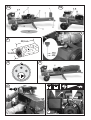
1 - DESCRIZIONE DELLA MACCHINA
SP21 è uno spaccalegna orizzontale trasportabile dotato di motorizzazione elettrica o a scoppio.
In fig.1 a pag.2 sono illustrate le varie parti della macchina.
1-
Lama
2-
Trave scorrevole
3-
Staffe di trattenimento del tronco
4-
Leve del comando ZHB
5-A - Motore a scoppio
5-B - Motore elettrico
6-
Filtro dell'olio idraulico
7-
Ruote per piccoli spostamenti
8-
Maniglia di trasporto
9-
Piede
10 - Serbatoio dell'olio
11 -
ZONA DI LAVORO CONSENTITA E OBBLIGATORIA
D22001620 - v.2 - UPD 010310
7
ITALIANO
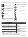
1.1 - Iconografia
Sulla macchina sono riportate segnalazioni grafiche normalizzate al fine di garantire la massima sicurezza relativamente a tutte le parti dello spaccalegna.
Per l’importanza di tali segnalazioni vi preghiamo di leggere attentamente quanto segue.
É vietato scaricare l’olio esausto nell’ambiente.
L’olio deve essere smaltito secondo le leggi in vigore nel
paese in cui viene effettuata tale operazione.
Leggere attentamente l’intero libretto di uso e manutenzione della macchina prima della messa in funzione.
Pericolo di taglio e schiacciamento della mano: non toccare mai le zone a rischio durante il movimento della
lama.
Al fine di evitare schiacciamenti dei piedi durante le normali operazione di carico e scarico dei ceppi di legno, è
obbligatorio indossare adeguate calzature di protezione.
Pericolo: attenzione al movimento dello spingitronco.
Per riparare le mani da schegge di legno o urti contro la
macchina è obbligatorio indossare adeguati guanti a
protezione di entrambe le mani.
Pericolo: non tentare di sbloccare un ceppo incastrato nella
lama usando le mani.
Per riparare gli occhi da schegge che possono prodursi
durante l'operazione di rottura del ceppo, è obbligatorio
indossare adeguati occhiali protettivi.
Pericolo: prima di effettuare qualsiasi intervento di manutenzione descritto nel presente libretto, staccare la spina
della macchina.
Lo spaccalegna deve essere utilizzato da una sola persona
Pericolo: tensione elettrica come indicato da targhetta.
B93250240
É vietato sostare nel raggio di azione della macchina
quando questa è in moto. Nessuna persona o animale
può sostare in un raggio di cinque metri dalla macchina
durante il normale funzionamento della stessa.
Le macchine dotate di apparecchiature elettriche non devono essere smaltite come rifiuti misti, ma attraverso una
raccolta differenziata separata, presso i punti autorizzati.
2 - CARATTERISTICHE TECNICHE
SP 21 E
SP 21 B&S
Lunghezza (mm)
~ 1100
~ 1100
Larghezza (mm)
~ 600
~ 600
Altezza (mm)
~ 510
~ 510
Peso (kg)
~ 59
~ 59
Massima forza di spinta (tons.)
~6
~6
Lunghezza max. di taglio (mm)
~ 535
~ 535
Capacità serbatoio olio (lt.)
~3
~3
Capacità totale olio (lt.)
~4
~4
Alimentazione
230V 50Hz Monofase
Benzina
Assorbimento
~ 11 A
-
2,5 CV - 1,85 kW
4 CV
Potenza
2.1 - Dimensioni del legno da rompere
In figura 2 a pag. 2 sono indicate le misure massime
dei tronchi da rompere.
Il diametro del legno è indicativo: un tronco di piccole
dimensioni può risultare difficoltoso da rompere se contiene nodosità oppure se è formato da fibra particolarmente attorcigliata.
2.2 - Olii consigliati
Vi consigliamo di usare i seguenti tipi di olio per il cilindro idraulico:
SHELL TELLUS T22
ARAL VITAM GF22
BP ENERGOL HCP22
TEXACO RANDO HDZ 22/32
MOBIL DTE11 o equivalenti.
NON USATE OLII CON GRADAZIONI DIFFERENTI.
Rumore ≤ 85 dB (A) misurati all'altezza dell'orecchio dell'operatore in posizione di lavoro,
a macchina operante.
• Sono obbligatorie adeguate protezioni per le orecchie (cuffie antirumore).
8
D22001620 - v.2 - UPD 010310
ITALIANO
3 - SICUREZZA
É estremamente importante leggere quanto riportato in questo capitolo. Esso contiene la descrizione dei possibili rischi generati dall’uso
della macchina e le relative informazioni atte a consentire un uso corretto della stessa ed evitare danni alle persone, agli animali e alle cose.
ATTENZIONE: lo spaccalegna BELL mod. SP21 è stato progettato e costruito al solo scopo di rompere ceppi di legno le cui dimensioni non siano
diverse da quelle raccomandate a pag.2 in fig.2.
Ogni altro uso è da ritenersi improprio ed il costruttore non risponde in alcun modo di eventuali danni a persone, animali od oggetti causati
da un uso erroneo della macchina.
É obbligatorio che l’operatore agisca soltanto dalla posizione consentita (11 in fig.1, pag.2) e che il comando di azionamento della macchina venga
manovrato con entrambe le mani, senza ricorrere ad espedienti diversi e senza manomettere il comando stesso.
In fase di lavoro non è consentita la presenza di persone ed animali ad una distanza inferiore ai 5 metri dalla macchina.
NON TENTARE DI MANOMETTERE LE PROTEZIONI DELLO SPACCALEGNA O DI LAVORARE SENZA DI ESSE.
IL MANCATO RISPETTO DI QUANTO RIPORTATO IN QUESTO CAPITOLO PUÒ CAUSARE GRAVI DANNI ALLE PERSONE E
AGLI OGGETTI NONCHÉ ALLA MACCHINA STESSA.
Non utilizzare lo spaccalegna per spezzare materiali lapidei (sassi, cemento, ecc.) né per schiacciare pezzi o contenitori in metallo.
3.1 - Regole generali di sicurezza
• La macchina deve essere usata da un solo operatore.
• Non usare la macchina all’esterno quando piove o nevica.
• Non si deve permettere l’uso dello spaccalegna a terzi se questi non ha letto il manuale di uso e manutenzione o se non è stato istruito sulle regole
•
•
•
•
•
•
•
•
•
•
•
•
•
•
•
•
•
da seguire per un corretto e sicuro uso.
L'uso della macchina è consentito solamente ai maggiorenni. L'uso dello spaccalegna da parte di apprendisti di età comunque non inferiore a 16
anni deve avvenire sotto la supervisione di un maggiorenne abilitato all'uso.
Non si devono indossare indumenti larghi o sbottonati o comunque che possano rimanere impigliati nelle parti in movimento della macchina.
Non usare le mani per cercare eventuali perdite di olio. Usare sempre un pezzo di carta o di legno.
Getti di olio sotto pressione possono penetrare sotto pelle. In questo caso, farsi subito visitare da un medico.
Non muovere o spostare lo spaccalegna mentre il motore è in movimento
Non si deve operare su un terreno in pendenza, accidentato o sdrucciolevole. Posizionate la macchina su un piano ben livellato e mantenere
l'area di lavoro libera da oggetti che potrebbero impedire la piena libertà d’azione dell’operatore.
Mantenere libero da detriti il piano di appoggio del tronco (2 e 3 in fig.1) e assicurarsi che l'area di lavoro dell'operatore rimanga sgombra da
ostacoli quali: ceppi, trucioli, segatura, ecc.
Controllate che i tronchi da spaccare siano privi di nodosità, chiodi, viti o fili di ferro che possono essere lanciati violentemente verso le persone
durante il taglio. Le estremità dei tronchi devono essere tagliate in squadro. I rami devono essere tranciati a filo del tronco.
Non tentate di tagliare ceppi di dimensioni superiori a quelle indicate in fig.2, pag.2: potrebbe essere pericoloso e si potrebbe danneggiare la macchina.
Posizionate il tronco in modo che venga spaccato nella direzione delle fibre. Diversamente può risultare pericoloso e può compromettere il
funzionamento della macchina.
Non cercate di tagliare due tronchi contemporaneamente: uno potrebbe essere sbalzato via colpendovi.
Se il tronco tende a scivolare via dalla lama, ritrarre la lama e ruotare il tronco di 90°
Non caricate il tronco mentre la macchina è in funzione: potreste impigliarvi e rimanere feriti.
Tenete le dita lontano dalle fenditure e dalle crepe che si formano sul tronco: queste potrebbero chiudersi improvvisamente causando gravi
schiacciature o addirittura amputazioni.
Non lasciate la macchina incustodita. Se dovete abbandonare il luogo di lavoro, togliete la fonte di alimentazione e fate attenzione a qualsiasi
possibile rischio di accensione accidentale.
Non usate mai lo spaccalegna sotto l'influenza di alcoolici, droghe, farmaci o se siete particolarmente stanchi. La lucidità è sostanziale per la
sicurezza ed una distrazione potrebbe causare incidenti anche gravi.
Non fatevi aiutare da terzi per disincastrare un ceppo bloccato.
Non utilizzate alcol, benzina o solventi per pulire la macchina. La leggibilità delle informazioni di sicurezza, applicate alla macchina stessa,
potrebbe essere pregiudicata irrimediabilmente.
3.1.A - Per macchine con motore elettrico (SP 21 E)
• Non usate la macchina in presenza di gas naturale, vapori di benzina o altri vapori infiammabili.
• Verificate che l’impianto elettrico che alimenterà la macchina sia idoneo.
•
Dovranno essere controllate tensione, frequenza di rete e potenza erogata (verificate la targhetta sul motore ed i dati nel presente manuale). La
macchina dovrà essere collegata ad un impianto dotato di salvavita differenziale adatto e in rispetto alle normative (corrente di guasto
nominale di 30 mA) e dovrà essere presente un adeguato impianto di messa a terra.
Usate cavi di sezione pari a 2,5 mm2. Non lavorate con connessioni volanti e non opportunamente isolate. I collegamenti devono essere fatti con
materiale protetto e adatto all'uso per esterno. Non usate prolunghe lunghe oltre 5 metri: cavi eccessivamente lunghi o di sezione
inadeguata possono provocare cadute di tensione che non permettono al motore di sviluppare tutta la sua potenza.
•
•
•
•
Prima dell'utilizzo verificare sempre che la prolunga sia priva di eventuali danni.
Non aprite mai la scatola del pulsante posta sul motore. In caso di necessità consultate il vostro elettricista di fiducia.
Verificate sempre che la macchina e il cavo siano lontani dall’acqua.
Non tirate il cavo di alimentazione per spostare la macchina, non date strattoni al cavo stesso e tenetelo lontano da fonti di eccessivo calore, olii,
solventi e oggetti taglienti.
Non lasciate mai la macchina incustodita se collegata all’impianto elettrico. Dopo l'utilizzo, la macchina deve essere sempre spenta e scollegata
dalla rete di alimentazione. In particolare quando si deve eseguire qualsiasi intervento di manutenzione.
D22001620 - v.2 - UPD 010310
9
ITALIANO
3.1.B - Per macchine con motore a scoppio (SP 21 B&S)
•
•
•
•
Se operate in zone aride prendete adeguate precauzioni al fine di evitare incendi.
Non fumate durante le fasi di lavoro, durante i rifornimenti di carburante o comunque in prossimità della macchina.
Non si deve rifornire lo spaccalegna di carburante mentre è in moto. Spegnete il motore, lasciatelo raffreddare ed eseguite il pieno di carburante
facendo attenzione a non far traboccare la benzina. Asciugatene eventuali fuoriuscite prima di mettere in moto.
Fate attenzione a non toccare il motore e il tubo di scarico poichè diventano caldissimi e possono provocare ustioni.
ATTENZIONE
NON AVVIATE LO SPACCALEGNA IN LOCALI CHIUSI: I GAS DI SCARICO SONO LETALI.
4 - MESSA IN FUNZIONE
Lo spaccalegna, in ottemperanza alla normativa EN 609-1, è azionato da un comando a due mani: la macchina entrerà in funzione solo azionando
entrambe le leve contemporaneamente (fig.6, pag.2).
Non usate mai lo spaccalegna se non è in perfetta efficienza o se necessita di manutenzione. Prima dell'utilizzo verificate che tutti i dispositivi di
sicurezza (comando a due mani e pulsante di spegnimento) funzionino come previsto.
Prima di iniziare a lavorare, verificate l'integrità dei tubi flessibili e l'assenza di perdite nei raccordi, controllate il livello dell’olio idraulico nel serbatoio
e, se necessario, rabboccate usando l’olio indicato a pag. 8.
Il livello dell’olio deve essere compreso fra le due tacche poste sullo stelo del tappo olio (fig.3, pag.2).
Prima di iniziare a lavorare accendete la macchina e lasciate riscaldare l’olio per alcuni minuti.
Dopo 200 ore di uso dalla prima messa in funzione, pulite il filtro dell’olio come indicato a pag.13, par.6.1.
4.1 - Disimballo e preparazione dello spaccalegna
Prima di mettere in funzione lo spaccalegna è necessario:
• Montare la maniglia di trasporto (fig.14A, pag.4)
Montate la maniglia come indicato in fig.14A e fissarla con le apposite viti.
• Sostituire il tappo dell'olio (fig.14B, pag.4):
Togliete il tappo trasparente (1) a chiusura dell'imbocco dell'olio e inserite il tappo con l'asta (2) fornito nel sacchetto allegato allo spaccalegna.
• Montare il piede (fig.14C, pag.4)
Montate il piede come indicato in fig.14C e fissarlo con le apposite viti.
• Montare l'assale ruote e le ruote (fig.14D, pag.4)
Infilate l'asse delle ruote (2) nei fori (1). Montate le ruote (3) sull'asse (2), bloccatele con la rondella elastica in dotazione (4) e chiudete il foro con il tappo
fornito (5).
4.2 - Avvertimenti
4.2.A - Per macchine con motore elettrico (SP 21 E)
Non aprite mai la scatola dell’interruttore posta sul motore o la morsettiera.
In caso di necessità consultate il vostro elettricista di fiducia.
Se saltano i fusibili o le protezioni, significa che si sta sovraccaricando il motore oppure che l’impianto elettrico non è adeguato: consultate il vostro
elettricista di fiducia.
4.2.B - Per macchine con motore a scoppio (SP 21 B&S)
•
•
•
Prima di azionare lo spaccalegna leggete attentamente il libretto di uso e manutenzione fornito dal costruttore del motore ed allegato al motore
stesso. Prendete visione delle norme di manutenzione e garanzia fornite.
Controllate il livello dell’olio nel basamento del motore. Se necessario rabboccate con olio consigliato dal costruttore del motore.
ATTENZIONE: lavorare senza olio può causare danni irreparabili al motore.
All’arrivo della macchina e al primo avviamento è importante lasciar girare a vuoto per almeno 20 minuti il motore. Questo rodaggio assicura un
buon funzionamento di tutto il sistema ed il massimo rendimento.
4.3 - Illuminazione
Tutte le zone della macchina devono essere illuminate in modo da garantire la loro perfetta visibilità durante il lavoro, le operazioni di manutenzione e
le regolazioni. Anche in caso di lavoro in esterni, è indispensabile che vi sia sufficiente luce per poter eseguire il lavoro in sicurezza. È vietato lavorare
durante orari in cui la scarsità di luce può causare una cattiva visibilità della macchina e dei suoi componenti (alba, crepuscolo, notte).
10
D22001620 - v.2 - UPD 010310
ITALIANO
5 - USO
5.1 - Accensione e spegnimento dello spaccalegna
ATTENZIONE
•
•
•
•
Non usare la macchina all’esterno quando piove o nevica.
In caso di non utilizzo, immagazzinare la macchina al riparo dagli agenti atmosferici.
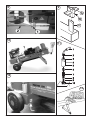
Per brevi spostamenti della macchina (fig.10, pag.3), utilizzare l'apposita maniglia (8 in fig.1, pag.2)
In caso di trasporto (es. carico su autoveicoli), assicurarsi che tutte le parti della macchina siano completamente raffreddate e la macchina sia
posizionata orizzontalmente.
5.1.A - Per macchine con motore elettrico (SP 21 E)
•
•
•
•
Verificate che l'interruttore/salvavita dell'impianto generale e l'interruttore della macchina siano spenti.
Collegate lo spaccalegna elettrico all'impianto di alimentazione inserendo l'apposita presa nella spina del motore elettrico.
Prestate attenzione a non far passare il cavo di alimentazione sopra alla trave telescopica, nelle vicinanze della lama o comunque in un posto in cui
potrebbe subire danni o troncarsi.
Armate l'interruttore generale quindi accendete lo spaccalegna premendo il tasto verde dell'interruttore.
La trave telescopica si porterà automaticamente in posizione di tutto aperto.
• Usate lo spaccalegna come spiegato nel paragrafo 5.2
• Se vi assentate spegnete lo spaccalegna, premendo il tasto rosso dell'interruttore (spento).
• Terminato il lavoro, togliete alimentazione alla macchina mettendo in posizione "0" (spento) l'interruttore/differenziale dell'impianto generale quindi
estraete la spina dalla presa sulla macchina. Nel compiere tale operazione, non tirate mai il cavo ma prendete il corpo della presa e toglietela.
5.1.B - Per macchine con motore a scoppio (SP 21 B&S)
Posizionate l'interruttore (A in fig.7, pag.2) posto sulla parte destra del motore su "ON"/"1".
• Portate la levetta del comando farfalla (B in fig.7) su "CHOKE" se il motore è freddo oppure su "RUN" se il motore è ancora caldo.
•
•
Posizionate il pomello dell'acceleratore (C in fig.7) tutto a destra (tartaruga).
Prendete il pomello di avviamento del motore (D in fig.7) fra le dita e, stringendolo bene, tiratelo con forza, ripetendo l'operazione fino a quando
il motore non si avvia. Fate attenzione durante questa fase, a non cadere e a non procurarvi lesioni o strappi.
Quando il motore si accende, la trave telescopica si porta in posizione di tutto aperto.
Portate lentamente l'acceleratore (C in fig.7) verso sinistra (lepre).
•
• Dopo pochi minuti dall'accensione a freddo spostate la levetta del comando farfalla (B in fig.7) da "CHOKE" a "RUN".
• Usate lo spaccalegna come spiegato nel paragrafo 5.2
• Se vi assentate o se avete finito il lavoro, spegnete lo spaccalegna utilizzando l'interruttore A in fig.7 ("OFF"/"0").
ATTENZIONE
Durante tutte le fasi di lavoro e dopo lo spegnimento, non toccate alcuna parte del motore perchè potreste scottarvi. Dopo lo
spegnimento attendete che il motore si sia raffreddato prima di compiere qualsiasi operazione.
Per ogni altro riferimento sul motore a scoppio BRIGGS & STRATTON consultate il relativo manuale allegato.
5.2 - Uso dello spaccalegna
•
•
•
•
Posizionate il ceppo di legno sulla trave come indicato in fig.5, pag.2. Le guide di appoggio (3 in fig.1,pag.2) aiutano a mantenere il ceppo al centro
della lama. Se il ceppo dovesse risultare instabile, riposizionatelo ruotandolo in modo che rimanga ben fermo sulla trave.
Operando solamente dalla posizione consentita (11 in fig.1, pag.2), tirate le due leve del comando ZHB e mantenetele in questa posizione fino
all'avvenuta rottura del tronco.
Nota: Se lasciate una sola delle due leve la macchina si bloccherà nella posizione in cui si trova.
Se lasciate entrambe le leve lo spingitronco ritornerà nella posizione iniziale, di tutto aperto.
Ripetete l'operazione con i pezzi ottenuti in modo da spaccare il ceppo in più parti.
Non forzate lo spaccalegna per più di alcuni secondi, tenendo il cilindro in pressione provando a rompere legna troppo dura.
Infatti, l’olio sotto pressione si surriscalda e la macchina potrebbe danneggiarsi. È conveniente desistere e provare a
ruotare il tronco di 90° per vedere se in altra posizione si riesce a romperlo. Se comunque non si dovesse riuscire significa
che la durezza del legno supera le capacità della macchina quindi si consiglia di scartarlo per evitare danni allo spaccalegna.
D22001620 - v.2 - UPD 010310
11
ITALIANO
5.3 - Regolazione della corsa della lama
Per risparmiare tempo è stato studiato un sistema che permette la regolazione della corsa della lama così da regolarla su tronchi corti facendole
compiere la corsa strettamente necessaria. Una volta verificata la lunghezza massima dei tronchi da tagliare, procedete alla regolazione come segue:
•
•
•
•
Azionate lo spaccalegna e portate la lama nella posizione desiderata quindi lasciate andare solamente una delle due leve di comando della
macchina in modo che la lama si fermi nella posizione che voi avete scelto.
Con l'altra mano svitate la vite a galletto (1 in fig.8, pag.3).
Tirate l'asta (2 in fig.8) verso l'esterno fino al suo bloccaggio.
Riavvitate la vite a galletto (1) serrando bene.
Ora lo spaccalegna si riposizionerà nel punto da voi regolato.
5.4 - Movimentazione dello spaccalegna
Lo spaccalegna mod.SP21 deve essere movimentato esclusivamente con la trave (2 in fig.1, pag.2) completamente rientrato nel corpo.
Per una movimentazione comoda e sicura (fig.10, pag.3) fate uso dell'apposita maniglia posta sulla trave telescopica (8 in fig.1, pag.2).
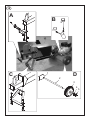
5.5 - Montaggio e uso della lama a 4 vie (optional)
Lo spaccalegna SP21 può montare, a richiesta, una lama a 4 vie per rompere un tronco in 4 ceppi con una sola mandata.
La lama a 4 vie (A in fig.9, pag.3) deve essere montata direttamente su quella a 2 vie (C) di serie.
Posizionate la lama a 4 vie inserendola a fondo e bloccatela stringendo bene la vite a galletto (B).
L'uso di questa lama è identico a quella a 2 vie avendo l'accortezza di non rompere legni molto duri o particolarmente nodosi in quanto, per la presenza
di 2 lame anzichè una, lo sforzo applicato alla lama stessa è maggiore.
ATTENZIONE
Non usate la lama a 4 vie senza averla bloccata con l’apposita vite (B) in dotazione: potrebbe risultare molto pericoloso per
l’operatore e per la macchina
6 - MANUTENZIONE ORDINARIA
In questo capitolo vengono descritte le operazioni di manutenzione ordinaria, pertanto quelle effetuate dall'operatore, sullo spaccalegna SP21 al fine
di mantenerlo sempre in perfetta efficienza e quindi affidabile per un uso continuativo e duraturo.
Ogni operazione di manutenzione ordinaria deve essere compiuta a macchina spenta e, nel caso di spaccalegna ad alimentazione elettrica, con il
cavo di alimentazione disconnesso dalla macchina.
Ogni altra operazione di manutenzione non specificatamente contemplata in questo manuale deve essere effettuata da personale
autorizzato in quanto si possono creare situazioni di pericolo per le quali l'operatore non è preparato.
Ogni operazione di manutenzione straordinaria o sostituzione di parti di ricambio non effettuate da personale specializzato, fanno
immediatamente decadere la garanzia e sollevano il costruttore da qualsiasi responsabilità per danni a persone, animali o cose.
6.1 - Pulizia del filtro dell'olio
Ogni 200 ore di lavoro è necessario pulire accuratamente il filtro dell'olio del sistema idraulico così da mantenerlo sempre in perfetta efficienza.
•
•
•
•
•
•
12
Come mostrato in fig.11, tenendo ferma la riduzione (3) con apposita chiave, svitate il raccordo (2) così da liberare il tubo (1).
Con chiave adeguata, svitate il corpo del filtro (5) facendo presa sulle scanalature laterali (4).
Aperto il filtro noterete al suo interno la molla di fermo (6), il filtro vero e proprio (7), la rondella (8) e l'o-ring di tenuta (9). Estraete le parti 6, 7, 8 e
9 e lavatele accuratamente con benzina fino a quando non risultino perfettamente pulite (in particolare il microfiltro 7).
Una volta pulite tutte le parti, rimettete l'o-ring di tenuta (9) nella relativa sede sul fondello (10), la rondella (8), il filtro (7), facendo attenzione che la
parte più stretta del filtro sia rivolta verso l'alto, ed infilate la molla (6) sul filtro (7).
Avvitate il corpo (5) sulla base (10) esercitando una leggera pressione e, una volta giunti a fine corsa, serrate accuratamente con la chiave.
Riavvitate il raccordo (2) sulla riduzione (3) e serrate con apposita chiave.
D22001620 - v.2 - UPD 010310
ITALIANO
6.2 - Sostituzione dell'olio idraulico
Ogni 600 ore di lavoro è necessario sostituire l'olio esausto con altro olio nuovo del tipo riportato a pag.8.
Per sostituire l'olio procedete come segue.
• Assicuratevi che la trave della macchina sia completamente rientrata (lama chiusa).
•
•
•
Mettete sotto al tappo di scarico olio (fig.12, pag.3) una vaschetta di raccolta che possa contenere circa 4 litri di olio.
Svitate il tappo di scarico con una chiave adeguata e lasciate scendere nella vaschetta tutto l'olio contenuto nel serbatoio.
Quando il serbatoio è completamente svuotato, pulite l'imbocco e il tappo di scarico con benzina, quindi riavvitate il tappo di scarico a fondo dopo
averlo avvolto con alcuni giri di nastro di teflon.
ATTENZIONE:
È estremamente importante avvolgere il grano con il nastro di teflon al fine di evitare trafilamenti di olio dal grano stesso e
successivi danni alla macchina.
•
•
•
•
•
Sfilate il tappo dell'olio (fig.3, pag.2) e riempite il serbatoio con olio adatto (Par. 2.2 - "Olii consigliati", pag.8), versandone circa 2,5 litri
Accendete lo spaccalegna e mettete in funzione la trave telescopica facendogli compiere 1/3 della corsa completa.
Aggiungete l'olio rimanente e fate compiere alla macchina due cicli completi per permettere la fuoriuscita dell'aria dal circuito idraulico.
Verificate con l'astina di livello che vi sia la giusta quantità di olio (fig.3, pag.2).
Pulite l'imbocco del tappo dell'olio e reinserite il tappo.
ATTENZIONE:
NON GETTATE L'OLIO ESAUSTO FRA I RIFIUTI GENERICI! L'OLIO ESAUSTO DEVE ESSERE SMALTITO SECONDO LE PRESCRIZIONI
DI LEGGE IN VIGORE NEL PAESE DI UTILIZZO DELLA MACCHINA.
NOTA: Tutta la manutenzione ordinaria del motore a scoppio (modello SP21-BS) è riportata sul relativo libretto allegato.
6.3 - Affilatura della lama
Dopo numerose ore di lavoro e comunque in caso di bisogno, affilate la lama dello spaccalegna usando una lima a denti fini e facendo attenzione ad
asportare anche eventuali bave o schiacciature del metallo.
7 - INCONVENIENTI E RIMEDI
7.1 - Disincastro del legno bloccato
•
•
•
Lasciate entrambe le leve del comando (4 in fig.1, pag.2): la lama si ritirerà completamente.
Inserite un cuneo di legno sotto al ceppo incastrato ed azionate lo spaccalegna fino a che il cuneo non viene spinto completamente sotto al ceppo
(fig.13, pag.3).
Ripetete l'operazione con cunei più grandi sin quando il ceppo si disincastra completamente.
ATTENZIONE:
• DURANTE LE OPERAZIONI DI DISINCASTRO DEL LEGNO NON FATEVI MAI AIUTARE DA TERZI.
• NON TENTATE DI DISINCASTRARE UN CEPPO COLPENDOLO CON UN ATTREZZO E TENENDO BLOCCATO IL PIEDE IN QUANTO
SI POTREBBE CAUSARE LA ROTTURA DEL PIEDE STESSO.
• PER TUTTE LE OPERAZIONI DESCRITTE IN PRECEDENZA VALGONO TUTTE LE REGOLE DI SICUREZZA DESCRITTE NEL CAP. 3
"SICUREZZA" A PAG. 9.
IL COSTRUTTORE NON RISPONDE IN ALCUN MODO PER DANNI ALLE PERSONE, AGLI ANIMALI E AGLI OGGETTI CAUSATI
DA UN USO IMPROPRIO DELLA MACCHINA O DALL'INOSSERVANZA DELLE NORME DESCRITTE.
D22001620 - v.2 - UPD 010310
13
ITALIANO
7.2 - Ricerca e soluzione dei problemi
La seguente tabella riporta i possibili problemi che possono verificarsi durante l'uso dello spaccalegna ed i relativi rimedi consigliati.
Ogni intervento da parte di personale non specializzato fa decadere immediatamente la garanzia della macchina e solleva il costruttore da qualsiasi
responsabilità per danni causati alle persone, agli animali e alle cose.
Problema
Probabile causa
Rimedio
Il tronco è di dimensioni più grandi di quelle
consentite
Cercare di tagliarne una piccola parte o ridurre con
altri mezzi la dimensione del tronco.
Errato posizionamento del tronco
Sistemare correttamente il tronco
La lama non taglia
Affilare la lama; controllare bave o tacche, limare
se necessario
Perdita di olio
Individuare la perdita usando un pezzo di carta o di
legno. Contattare il rivenditore.
Pressione idraulica troppo bassa
Contattare il rivenditore
Lo stelo avanza a scatti o con forti vibrazioni. Esce olio schiumoso dal tappo di
riempimento.
Presenza di aria nel circuito
Controllare il livello dell'olio e, se necessario, aggiungerne. Controllare che la pompa non aspiri aria.
Verificare che, nel tratto di circuitoche va dal
serbatoio alla pompa, i raccordi non siano lenti o
il tubo danneggiato.
Se il problema persiste contattate il rivenditore.
Perdita di olio dai raccordi, dalla pompa
o dal cilindro
Raccordi lenti
Stringere i raccordi
Guarnizioni usurate
Contattare il rivenditore
Il tronco non si spacca
7.3 - Riarmo della protezione termica del motore elettrico
Durante il lavoro con macchine alimentate elettricamente, nel caso di un sovraccarico, uno sbalzo molto forte di tensione oppure un guasto accidentale
all'impianto elettrico, interverrà un dispositivo di protezione applicato al motore e integrato nell'interruttore generale. in caso di intervento della protezione, prima di chiamare il centro di assistenza autorizzato, attendete alcuni minuti quindi provate a riarmare l'interruttore generale. Se non si ripresenta
il problema, potete usare la macchina tranquillamente. Se invece la protezione dovesse saltare ancora, non insistete nel tentativo di farla rimanere
agganciata e contattate il centro di assistenza tecnica autorizzata.
DEMOLIZIONE E SMALTIMENTO DELLA MACCHINA
La demolizione della macchina deve essere eseguita rispettando tutte le norme di sicurezza atte ad evitare danni alle persone, all'ambiente e agli
animali.
Tutte le parti della macchina devono essere rottamate e smaltite secondo le leggi vigenti nel luogo in cui viene effettuata la demolizione.
Particolare attenzione è da porre nello smaltimento dell'olio idraulico e delle apparecchiature elettriche. Entrambe non devono essere dispersi
nell'ambiente in quanto altamente inquinanti, ma devono essere smaltiti secondo le prescrizioni di legge.
Le macchine dotate di apparecchiature elettriche non devono essere smaltite come rifiuti misti, ma attraverso una raccolta differenziata separata,
presso i punti autorizzati.
Il produttore è impegnato nel riciclaggio dei rifiuti (RAEE) attraverso l'adesione agli appositi consorzi di smaltimento.
Uno smaltimento non conforme alle prescrizioni di cui sopra è sanzionabile a norma di legge.
14
D22001620 - v.2 - UPD 010310
ITALIANO
GARANZIA
La ditta BELL S.r.l., denominata qui di seguito come BELL, garantisce al compratore di ogni nuovo prodotto originale BELL, acquistato da un rivenditore
autorizzato BELL, che tale prodotto è esente da difetti di materiale e manodopera per un periodo di 360 giorni (12 mesi) dalla data dell’acquisto
originale o dalla data del primo noleggio.
Le parti di ricambio installate sul prodotto coperto da questa garanzia, sono garantite per 90 giorni (3 mesi) dalla data di sostituzione o riparazione.
Tali parti devono essere fornite gratuitamente all’utilizzatore dal rivenditore o distributore BELL durante le ore lavorative regolari.
BELL si riserva il diritto di ispezionare ogni prodotto o parte sostituita come difettosa. Le parti sostituite devono quindi essere conservate e tenute a
disposizione per 12 mesi.
È espressamente inteso che la BELL non ha obblighi di fornire manodopera o di accettare spese di trasporto.
BELL non si assumerà alcuna responsabilità per danni, difetti o costi derivanti da riparazioni e/o modifiche di un prodotto BELL, effettuati da qualsiasi
persona che non sia un tecnico autorizzato BELL.
Questa garanzia non sarà applicata ai componenti commerciali coperti da loro propria garanzia, quali motori a scoppio, diesel, ecc...
Non sono coperte da garanzia macchine o loro parti deteriorate da:
1) Uso scorretto o improprio, negligenza, abuso o incidente.
2) Mancanza di ragionevole o necessaria manutenzione come prescritto in questo manuale (Sostituzione di olio idraulico, olio motore, olio per
moltiplicatore consumati o esausti, lama non affilata, ecc...)
3) L’uso di parti o accessori non costruiti, forniti o approvati da BELL.
La BELL non presta ulteriori espresse o sottintese garanzie, eccetto quelle qui contenute.
Ogni prolungamento del periodo di garanzia o estensione della stessa non verranno riconosciuti come validi e quindi applicati dalla BELL.
(Nessun rappresentante o rivenditore è autorizzato ad assumere altre responsabilità riguardo ai prodotti BELL.
La durata delle garanzie implicite riconosciute dalla legge, incluse le garanzie commerciali e convenienze per particolari scopi sono limitate
nella durata alla validità e durata della espressa garanzia qui sotto concesse.)
In nessun caso la BELL riconoscerà perdite di profitto, dirette o indirette, speciali o conseguenti a eventuali danni.
In caso di richiesta di ricambi o interventi di riparazione, sono indispensabili le seguenti informazioni:
MODELLO ........................................................................................................
NUMERO DI SERIE .........................................................................................
DATA DI ACQUISTO ........................................................................................
D22001620 - v.2 - UPD 010310
15
ENGLISH
TRANSLATION OF ORIGINAL INSTRUCTIONS
INTRODUCTION
BELL® log splitters have been designed and manufactured in compliance with the most recent European safety regulations with particular reference
to the EN 609-1 and CEI EN 60204-1 standards.
The two-hands control systems, in fact, have been designed and engineered so that the operator is forced to work in the safety area, employing
both the hands, without any possibility of inserting hands or arms in dangerous areas.
This log splitter machine is produced in conformity with the specifications contained in the RoHs directive 2002/95/CE
Before transporting, installing or operating the machine, read all parts of this manual, paying particular attention to the specific
safety regulations.
Operators who are unable to understand any of the languages in which this manual is written are responsible for asking the retailer to provide a
manual in their own language.
The operator must also train any other person authorised to use the machine.
Failure to comply in any way with these instructions, improper use of the machine, extraordinary maintenance operations not
carried out by skilled, authorised personnel, removal of data plates or markings of any type, removal or tampering with the
guards and safety mechanisms of the machine or any other action not expressly authorised that may impair the active and
passive safety systems of the machine shall relieve the manufacturer of all and any liability and may result in serious injury and
damage.
If the machine is tampered with in any way by unauthorised personnel, the guarantee is automatically null and void. This manual is an integral part
of the machine and must accompany it even in the case of transfer of ownership.
WARNING: The ignition system of your machine produces an electromagnetic field of very low intensity. This field could interfere
with certain pacemakers. To reduce the risk of serious or fatal injury, persons with pacemakers should consult their doctor or the
manufacturer of the pacemaker before using this machine.
1 - DESCRIPTION OF THE MACHINE
SP21 is a portable horizontal log splitter equipped with electric motor or gasoline engine.
The various parts of the machine are shown in fig.1, page 2.
1-
Wedge
2-
Telescopic mast
3-
Log retention brackets
4-
ZHB control levers
5-A - Gasoline engine
5-B - Electric motor
6-
Hydraulic oil filter
7-
Wheels for minor movements
8-
Carrying handle
9-
Foot
10 - Oil tank
11 - Permitted and mandatory work area
16
D22001620 - v.2 - UPD 010310
ENGLISH
1.1 - Symbols used
Standard graphic symbols are used on all machines in order to ensure complete safety of all parts of the log splitter. As these symbols are very
Dumping of used oil in the environment is forbidden. The
oil must be disposed of according to current legislation in
the country where this operation is carried out.
It's necessary to read carefully the entire use and
maintenance manual of the machine, before using it
Danger of cutting or crushing of the hand: never touch
hazardous areas while the wedge is moving.
it is obligatory to wear safety footwear at all times to
provide protection against the risk of logs accidentally
falling on feet.
Warning: always pay attention to the movement of the log
pusher.
it is obligatory at all times to wear gloves which protect
the hands against chips and splinters which may be
produced during work.
Warning: never remove a log trapped in the wedge with
your hands.
it is obligatory at all times to wear goggles which
protects the eyes against chips and splinters which
may be produced during work.
Warning: Before carrying out any maintenance operation
described in this manual, disconnect the plug of the
machine.
The log splitter must be used by one person alone.
Warning: voltage as indicated on the rating plate
B93250240
it is forbidden to stand in the range of action of the
machine. apart from the operator, no other person or
animal may be present within a radius of 5 metres from
the machine.
Machines fitted with electrical parts must not be disposed
of as general waste and must be separated for disposal
as separately collected fractions, deposited at authorised
collection points.
2 - TECHNICAL DATA
SP 21 E
SP 21 B&S
Lenght (mm)
~ 1100
~ 1100
Widht (mm)
~ 600
~ 600
Height (mm)
~ 510
~ 510
Weight (kg)
~ 59
~ 59
Max. force (tons.)
~6
~6
Log capacity (mm)
~ 535
~ 535
Hydraulic oil tank capacity (lt.)
~3
~3
Hydraulic oil total capacity (lt.)
~4
~4
230V 50Hz 1-phase
Premium graded fuel
~ 11 A
-
2,5 CV - 1,85 kW
4 CV
Supply
Absorption
Power
2.1 - Size of the logs to be split
Figure 2 on page 2 shows the maximum log sizes
that can be split.
The diameter of the log is indicative: a small log can
be difficult to split if it has knots or is of a particularly
twisted fibre.
2.2 - Recommended oils
We recommend use of the following oils for the
hydraulic cylinder:
TEXACO RANDO HDZ 22/32
SHELL TELLUS T22
ARAL VITAM GF22
BP ENERGOL HCP22
MOBIL DTE11 or equivalent
DO NOT USE OTHER GRADE OILS.
Noise ≤ 85 dB(A) measured at the height of the operator’s ear in the working position
with the log splitter in operation
• The ears must be suitably protected (ear defenders).
D22001620 - v.2 - UPD 010310
17
ENGLISH
3 - SAFETY
The information given in the chapter is extremely important for safety purposes. It describes possible hazards tied to use of the
machine and instructions for correct use of this to avoid injury or damage.
WARNING: This log splitter has been designed and manufactured to split logs of the sizes recommended in fig.2, page 2 only.
Use of the machine for any other purpose shall be considered improper and the manufacturer shall not be liable for any injuries
or damage to be ascribed to improper use of the machine.
The operator must only work in the position shown in fig.1, pos.11, and only operate the machine drive control (ZHB) with both hands without using
other makeshift systems or tampering with the ZHB control.
When the machine is being used, persons other than the operator and animals must be keep at a distance of at least 5 meters from the machine.
NEVER ATTEMPT TO TAMPER WITH THE PROTECTIONS OF THE LOG SPLITTER OR TO OPERATE THE MACHINE WITHOUT THESE.
FAILURE TO COMPLY WITH THE INSTRUCTIONS GIVEN IN THIS CHAPTER MAY RESULT IN SERIOUS INJURY OR DAMAGE TO
PERSONS, THINGS AND TO THE MACHINE.
Do not use the log splitter to break stone materials (stones, concrete, etc.). Or to crush pieces or metal containers.
3.1 - General safety regulations
• The machine must always be used by one operator only.
• Do not use the machine outdoor when it is raining or snowing.
• Nobody must be allowed to use the log splitter unless they have read the instruction manual and have been instructed in the regulations to follow
•
•
•
•
for correct and safe use.
The machine must be used by adults only. Use of the log splitter by apprentices of not less than 16 years of age must be supervised by an adult
authorised to use the machine.
Never wear loose, unbuttoned clothing which may become trapped in moving parts.
Do not move the log splitter while the motor is running.
Use a piece of cardboard or wood rather than the hands in order to search for eventual oil leakages.
Oil jets under pressure can penetrate under skin. In this case, see a doctor at once.
•
•
•
•
•
•
•
•
•
•
•
•
•
•
Do not work on sloping or slippery ground. position the machine in a flat area free from objects which may impede the freedom of movement of
the operator.
Check that the logs to be split are free from nails or wire, which may fly up or damage the machine. The ends of the logs must be cut square.
Branches must be cut off flush with the trunk.
Never try to split logs larger than those indicated in fig. 2. This could be dangerous and may damage the machine.
Break wood in the direction of the grain. Do not place wood across the log splitter and leave it in that position for splitting; it may be dangerous
and may seriously damage the machine.
Never attempt to cut two logs at once; one may fly up and hit you.
If the log moves away from the blade, retract the ram or the blade and turn the log through 90°.
Do not attempt to load the log in the log splitter while the ram is in motion. you could get trapped and injured.
Keep your hands well away from any splits and cracks which open in the log; these may close suddenly and crush or amputate your fingers.
Do not force the log splitter for more than 30 seconds by keeping the cylinder under pressure at the end of its stroke, or by persisting when a
log does not split or gets stuck on the blade. Oil under pressure overheats very rapidly, damaging the pump.
Never leave the machine unattended while it is running. If you leave the machine, even for a short time, remove the power supply or any possible
cause of accidental start-up.
The log splitter must never be used by an operator who is under the influence of alcohol, drugs, medicines, or who is tired. A clear mind is
essential for safety.
Never try to release a jammed log while the machine is running. The machine must be switched off during this operation.
Never request the assistance of another person to help you remove a jammed log.
Do not use alcohol, petrol, or solvents to clean the machine. This could cause the safety information applied to the machine itself to become illegible.
3.1.A - For machines with electric motor (SP 21 E)
• Do not use machines with electric motor if natural gas, petrol fumes or other inflammable vapours are present.
• Check that the electric circuit to which the machine will be connected is suitable. Power, voltage and frequency of the motor
•
•
•
•
•
18
must be checked (verify the nameplate on the motor and the data in this manual). The machine must be connected to a circuit with a regulation
differential switch upstream and, in compliance with the norms (30 mA rated fault current), with a ground connection.
Use cables with a section of 2.5 mm2. Avoid use of free and inadequately insulated connections. Connections must be made with protected
material suitable for outdoor use. Do not use cable extensions longer than 5 mt.: too long cables or cables with inadequate
section may cause voltage drops and don’t allow the motor to develop all the power. Always check the cable extension for any
damage before using it.
Make sure that the machine and the cable never come in contact with water.
To prevent accidental start-up, ensure that the switch is “off” before plugging in the power cable.
Treat the power cable with care. do not attempt to move the machine by pulling the cable. do not yank the cable to unplug it; keep the cable away
from excessive heat, oil and sharp objects.
Never leave the machine unattended with the power supply “on”. After use, always switch the machine off and disconnect it from the power
supply, especially when any maintenance work is required.
D22001620 - v.2 - UPD 010310
ENGLISH
3.1.B - For machines with premium graded fuel engine (SP 21 B&S)
•
•
•
•
take the necessary precautions against fire when working in dry areas.
do not smoke while working or refuelling.
never refuel the log splitter while it is running. switch the engine off and leave it to cool. fill with fuel taking care that the tank does not overflow.
wipe off any traces of petrol before starting up. Handle fuel with care.
Never touch the engine or the exhaust pipe as they become very hot and may cause burns.
WARNING
DO NOT START THE ENGINE IN AN ENCLOSED SPACE; EXHAUST FUMES ARE LETHAL.
4 - OPERATING THE MACHINE
The log splitter, in compliance with standard EN 609-1, is activated with a two hand control: the machine will function only when both the
levers are activated together (fig.6, page 2).
Never use the log splitter if it is not in perfect order or if it needs servicing. Before starting work, check correct functioning of all the safety devices
(two hands control and switch-off button).
Before starting work, check the integrity of the flexible pipes and the lack of leaks in the connections, check the level of the hydraulic oil in the tank
and top up if necessary with one of the oils indicated on page 20.
The oil level must be between the two notches on the oil dipstick (fig.3, page 2)
Before starting work, switch on the log splitter and let the oil warm up for a few minutes.
After 200 hours of use, clean the oil filter as explained on page 22 paragraph 6.1 before starting the machine.
4.1 - Unpacking and preparing the log splitter
Before operating the machine, it is necessary:
• Assemble the carrying handle (fig.14A, page 4)
Assemble the carrying handle as shown in fig.14A and secure it with the appropriate screws supplied
• Replace the oil cap (fig.14B, page 4)
Remove the transparent oil sump cap (1) and fit the cap with the rod (2) supplied in the bag attached to the log splitter.
• Assemble the foot (fig.14C, page 4)
Assemble the foot as shown in fig.14C and secure it with the appropriate screws supplied
• Assemble the axle and the wheels (fig.14D, page 4)
Insert the axle (2) into the appropriated holes (1) and the wheels (3) on the axle (2). Block the wheels using the elastic washer (4) and cover the hole
on the wheel with the plastic cap (5) supplied.
4.2 - Warnings
4.2.A - For machines with electric motor (SP 21 E)
Never open the box containing the switch, or open the terminal block on the motor. if it is necessary to do
so, have these operations carried out by your electrician.
If the fuses blow or the protection valve trips, this means that you are overloading the motor or the electrical installation is not correctly rated. Consult
your electrician.
4.2.B - For machines with premium graded fuel engine (SP 21 B&S)
•
•
•
Before operating the log splitter, carefully read the user’s manual for the engine fitted. study the maintenance regulations and guarantee supplied.
Check the oil level in the engine block. top up if necessary.
WARNING: working without oil causes irreparable damage.
When the engine is new, it is important, at first start-up, to let it turn over without performing any work for at least twenty minutes. this runningin period ensures maximum performance and smooth operation of the whole system.
4.3 - Lighting
Lighting must be provided in the entire work area of the log splitter to ensure perfect visibility when operating the machine and during maintenance
and adjustments. Even when working outdoors, there must be sufficient light to work safely. Working at times when insufficient light may result in
poor visibility of the machine and its components (dawn, dusk, night) is forbidden.
D22001620 - v.2 - UPD 010310
19
ENGLISH
5 - USE
5.1 - Switching on/off of the machine
WARNING:
•
•
•
•
Do not use the machine outdoor when it is raining or snowing.
When not in use, store the machine where it is protected from atmospheric agents.
To move the machine for short distances (fig.10, page 3) use the appropriate handle (8 in fig.1, page 2).
When transporting (e.g. loaded on motor vehicles), ensure that all parts of the machine have cooled down completely, the bleeder screw is
screwed up, and the machine is positioned horizontally.
5.1.A - For machines with electric motor (SP 21 E)
•
•
•
•
Make sure that the switch/cutout of the general power system and the switch of the machine are OFF.
Connect the electric log splitter to the power system inserting the plug in the socket on the electric motor.
Never pass the power cable over the telescopic mast, close to the wedge or anywhere where it may be damaged or cut.
Set the main on/off switch and then press the switch in the green area to start the log splitter.
The telescopic mast will move automatically to the fully open position.
• Use the log splitter as explained in paragraph 5.2.
• Never leave the log splitter unattended without first of all pressing the switch in the red area (off).
• On completing the work, switch off the log splitter by turning the switch/differential of the general power system to the “0” position (off) and then
remove the plug from the socket on the machine. Never yank the plug using the cable. Grasp the body of the plug and pull it firmly.
5.1.B - For machines with premium graded fuel engine (SP 21 B&S)
Set the switch (A in fig.7, page 2) on the right of the motor to “ON”/“1”.
• Switching on: Turn the throttle control knob (B in fig.7) to “CHOKE” if the engine is cold or to “RUN” if the engine is still warm.
•
•
Move the accelerator knob (C in fig.7) completely to the left (tortoise).
Grasp the engine start-up knob (D in fig.7) and holding it tightly pull it firmly. Repeat this operation until the engine starts. During this phase, be very
careful not to slip or cause injuries or distortions. Once the engine is running, the telescopic mast moves to the fully open position.
Slowly move the accelerator knob (C in fig.7) to the right (hare).
•
• After a few minutes from cold starting, move the throttle control knob (B in fig.7) from “CHOKE” to “RUN”.
• Use the log splitter as explained in par. 5.2.
• If you are leaving the log splitter unattended or if you have finished working, switch off the log splitter using the switch A in fig.7 (“OFF”/“0”)
WARNING
When working and after switching off the log splitter, never touch any part of the engine as this could cause burns. After
switching off the machine, wait until the engine has cooled before performing any operation.
Refer to the attached manual for any other information regarding the BRIGGS & STRATTON engine.
5.2 - How to use log splitter
•
•
•
•
20
Place the log on the work surface as shown in fig.5, page 2. The log retention brackets (3 in fig.1a, page 2) help to keep the log at the centre of
the wedge. If the log tends to wobble, it must be repositioned turning it so that is remains firmly on the beam.
From the permitted position only (11 in fig.1, page 2), activate both the levers of the two hand control. Pull the levers of the two hands control and
hold them in this position until the log is completely split.
Note: If you release one of the two levers only, the machine will stop in its current position.
If you release both the two levers, the log pusher come back to the start position, fully open position.
Repeat the operation with the pieces obtained so as to split the log into several parts.
Never force the log splitter for more than a few seconds keeping the cylinder under pressure in the attempt to split
excessively hard wood. The oil under pressure, in fact, is overheated and the machine could be damaged. It is thus better
to stop and rotate the log by 90° to see whether it can be split in a different position. In any case, if you are not able to split
the log, this means that its hardness exceeds the capacity of the machine and thus that log should be discarded so as not
to damage the log splitter.
D22001620 - v.2 - UPD 010310
ENGLISH
5.3 - How to adjust blade stroke
In order to save time, a system has been designed that makes it possible to adjust wedge travel so that this can be set for short logs. In this way, the
wedge travels for the distance required only. After checking the length of the longest logs to be split, regulate wedge travel as follows:
•
•
•
•
Start the log splitter and bring the wedge to the position required. Release one of machine control levers so that the wedge stops in the selected
position.
With your other hand, loosen the wing nut (1 in fig.8, page 3).
Pull the rod (2 in fig.8) outward until it locks.
Retighten the wing nut (1) thoroughly.
The log splitter will now reposition at the point selected.
5.4- Moving the log splitter
The log splitter SP 21 must be moved only with the mast (2 in fig.1a, page 2) completely closed, as shown in fig.10, page 3.
Use the appropriate carrying handle on telescopic mast (8 in fig.1a, page 2) for safe, trouble-free transport of the log splitter.
5.5 - Assembly and use of the 4-way-wedge (optional)
The log splitter mod.SP 21 can be equipped on request with a 4-way-wedge, in order to split a trunk into four logs with a single stroke.
The 4-way-wedge (A in fig.9, page 3) must be assembled directly on the standard 2-way-wedge (C).
Position the additional wedge by inserting it completely and fasten it in place by tightening the butterfly screw (B).
The 4-way-wedge is used in the same way as the 2-way wedge taking care, however, not to split very hard wood or wood with a large number
of knots as the use of 2 wedges instead of 1 causes greater stress on the wedge.
WARNING
Never use the 4-way-wedge if it has not been secured into position with the butterfly screw (B) supplied, as this could prove
very dangerous for both the operator and the machine.
6 - ROUTINE MAINTENANCE
This chapter describes routine maintenance, i.e. operations carried out by the operator, on the log splitter to keep it in perfect working order and
therefore reliable for continuous, long-term use. All routine maintenance operations must be carried out with the machine off and in the case of log
splitters with electric motor with the power cable disconnected.
Any other maintenance operation not specifically envisaged in this manual must be carried out by authorised personnel only in
that hazardous situations may arise for which the operator is not prepared.
In the case in which extraordinary maintenance or part replacement operations are not carried out by authorised personnel, the
guarantee shall be immediately null and void and the manufacturer shall be relieved of any responsibility for injury to persons or
animals or damage.
6.1 - How to clean the oil filter
To keep the machine in perfect working order, the oil filter of the hydraulic system must be thoroughly cleaned every 200 hours of operation.
•
•
•
•
•
•
As shown in fig.11, block the reducer (3) with a suitable wrench and loosen the fitting (2) so as to free the pipe (1).
With a suitable wrench, unscrew the body of the filter (5) using the side grooves (4).
On opening the filter, you will see the lock spring (6), the actual filter (7), the washer (8) and the seal (9). Extract parts 6, 7, 8 and 9 and wash
thoroughly with petrol until they are perfectly clean (in particular, the microfilter 7).
Once all the parts are clean, replace the seal (9) in its housing in the base (10), , the washer (8), the filter (7), making sure that the narrower part
of the filter is facing upwards, and then insert the spring (6) on the filter (7).
Screw the body (5) to the base (10) with a slight pressure and, when the end of stroke position has been reached, tighten it with the wrench.
Screw the fitting (2) back on the reducer (3) and tighten with a suitable wrench.
D22001620 - v.2 - UPD 010310
21
ENGLISH
6.2 - How to change the hydraulic oil
The spent oil must be replaced with new oil of the type indicated on page 17 every 600 hours of operation.
To change the oil, proceed as follows.
• Make sure that the mast of the machine is fully retracted (wedge closed).
•
•
•
Place a collection tray, able to hold around 4 litres of oil, under the oil drainage dowel (fig.12, page 3).
Unscrew the drainage plug with a suitable wrench and let all the oil in the tank drain into the collection tray.
Once the tank is empty, clean the inlet and the drainage plug with petrol, wind a few turns of Teflon tape around the drainage plug and screw
it back into place
WARNING:
It is extremely important to wind the Teflon tape around the drainage plug to prevent oil leakage from this with consequent
damage of the machine.
•
•
•
•
•
Remove the oil plug (fig.3, page 2) and fill the tank with suitable oil (see page 17 for oils to be used), pouring in around 2,5 litres.
Switch on the log splitter and activate the telescopic mast for 1/3 of its complete travel.
Add the remaining oil and run the machine for two complete cycles to bleed any air from the hydraulic circuit.
Using the oil rod (fig.3 page 2), check the right amount of oil.
Clean the inlet of the oil plug and replace the plug.
WARNING:
NEVER MIX OIL WITH GENERAL WASTE!
USED OIL MUST BE DISPOSED OF ACCORDING TO CURRENT REGULATIONS IN THE COUNTRY WHERE THE MACHINE IS USED.
NOTE: For routine maintenance of the petrol or diesel engine (for model SP21-BS), refer to the related attached booklet.
6.3 - Sharpening the wedge
After long periods of operation and when required, sharpen the wedge of the log splitter using a fine-toothed file and taking care to remove any burrs
or crushed parts of the metal.
7 - TROUBLESHOOTING
7.1 - How to free a jammed log
•
•
•
Release both levers of the control (4 in fig.1, page 2): the wedge will be fully retracted.
Insert a triangular block of wood under the jammed log and activate the log splitter until the wedge is pushed completely under the piece of wood
(fig.13, page 3)).
Repeat the operation with larger pieces of wood until the log is completely free.
WARNING:
•
•
•
NEVERASK FOR THE ASSISTANCE OFANOTHER PERSON WHEN FREEING AJAMMED LOG.
NOT TO TRY TO EXTRACT THE LOG HITING IT WITH A TOOL AND KEEPING THE FOOT BLOCKED, THIS COULD CAUSE THE
BREAKAGE OF THE FOOT.
ALL THE SAFETY RULES DESCRIBED IN CHAPTER 3 “SAFETY” ON PAGE 18 APPLY WHEN CARRYING OUT THE OPERATIONS
DESCRIBED ABOVE.
THE MANUFACTURER SHALL NOT BE HELD RESPONSIBLE IN ANY WAY FOR INJURY TO PERSONS AND ANIMALS OR DAMAGE TO
OBJECTS CAUSED BY IMPROPER USE OF THE MACHINE OR FAILURE TO COMPLY WITH THE REGULATIONS DESCRIBED.
22
D22001620 - v.2 - UPD 010310
ENGLISH
7.2 - Troubleshooting
Problems that may arise when using the log splitter and recommended remedies are given in the table below. In the case of operations carried out
by unauthorised personnel, the guarantee will be immediately null and void and the manufacturer will be relieved of any responsibility for injury to
persons and animals and damage.
Problem
Log fails to split
Probable cause
Corrective action
Log exceeds permitted dimensions
Try to cut a small part or use other means to
reduce the size of the log
Incorrect positioning of the log
Change the position of the log in relation to the
wedge
Wedge do not cut
Sharped the wedge, check for burrs or nicks,
file if necessary
Oil leack
Locate the leack using a piece of card or wood.
Contact your dealer
Hydraulicpressure too low
Contact your dealer
Rod advances jerkily or with strong
vibrations. Foamy oil comes out from the
filler cap.
Air in the circuit
Check oil level. Top up if necessary.
Check that the pump does not suck up any air.
Check that the connections are not restricted or
the pipes damaged in the system from the tank
to the pump.
If problem remain contact your dealer
Oil leak from the unions, pump or cylinder
Unions not properly tight
Tighten unions
Seals worn
Contact your dealer
7.3 - Resetting of the thermal cut-out of the electric motor
In the case of machines with electric motor, a protection device applied to the motor and integrated in the main on/off switch is tripped in the case of
overloads, sudden increases in voltage or accidental faults in the electrical system. In this case, before calling your authorised service centre, wait
a few minutes and then try to reset the main on/off switch. If the problem does not re-occur, the log splitter can be used normally. If the cut-out is
tripped again, do not try to reset it and contact your ahthorised service centre.
SCRAPPING AND DISPOSAL OF THE MACHINE
The log splitter must be scrapped in compliance with all safety regulations for the prevention of personal injury and damage to the environment and
animals.
All parts of the log splitter must be scrapped and disposed of in accordance with applicable legislation in the place of scrapping.
Dispose of hydraulic fluid and electric parts correctly. Do not dispose of these in the environment, as they are hazardous pollutants, and treat them
in accordance with applicable legislation.
Machines fitted with electrical parts must not be disposed of as general waste and must be separated for disposal as separately collected fractions,
deposited at authorised collection points.
The manufacturer is committed to waste recycling (WEEE) and is a member of specialised waste disposal consortiums.
Incorrect waste disposal is punishable by law.
D22001620 - v.2 - UPD 010310
23
ENGLISH
GUARANTEE
The company BELL, referred to hereinafter as BELL, guarantees to the purchaser of every new BELL original product, purchased from a BELL
authorized dealer, that the product shall remain free from any defects in materials or workmanship for a period of 360 days (12 months) from the
original date of purchase or the date of first hire.
Spare parts installed on the product covered by this guarantee are guaranteed for 90 days (3 months) from the date of their repair or renewal.
Such parts must be supplied free of charge to the user by a BELL dealer or distributor during normal working hours.
BELL reserves the right to inspect any product or part which has been substituted as defective. Substituted parts must therefore be kept available
for 12 months.
It is expressly understood that BELL shall be under no obligation to provide labour or accept transport expenses.
BELL shall accept no responsibility for any damage, defect or costs deriving from repairs and/or modifications of a BELL product, effected by any
person other than an authorized BELL representative.
This guarantee does not apply to commercial components covered by their own guarantee, such as internal combustion engines, diesel engines,
etc..
This guarantee covers only defects arising during proper use of the machine. BELL shall accept no responsibility whatsoever if BELL components
break while under guarantee for reasons such as:
1) Misuse, negligence, improper handling, abuse or accident.
2) Failure to carry out reasonable or necessary maintenance as prescribed in this manual (renewal of worn components such as slides, hydraulic
oil, engine oil, gearbox oil; blade not sharpened, etc.)
3) The use of parts or accessories not manufactured, supplied or approved by BELL.
BELL does not provide further explicit or implied guarantees, other than those set forth herein.
(No representative or dealer is authorized to assume other responsibilities with regard to BELL products. The duration of the
implicit guarantees recognized by the law, including the commercial guarantees and conventions for particular purposes are
limited in duration to the validity and duration of the explicit guarantee granted below)
BELL shall upon no account act as guarantor for loss of profit, whether direct or indirect, specific or deriving from any damage.
If you require spare parts or repair work it will be useful the followins informations:
MODEL.............................................................................................................
SERIAL NUMBER ...........................................................................................
DATE OF PURCHASE.....................................................................................
24
D22001620 - v.2 - UPD 010310
DEUTSCH
ÜBERSETZUNG DER ORIGINALANLEITUNGEN
EINLEITUNG
Lesen Sie aufmerksam diese Betriebsanleitung, befolgen Sie die Anweisungen und Sie werden das Beste von Ihrem Holzspalter.
Die Holzspalter BELL sind in Entsprechung den letzten europäischen Sicherheitsnormen, insbesondere EN 609-1 und CEI EN 60204-1, geplant und
gebaut.
Die Zweihand-Steuersysteme wurden entwickelt, um den Bediener zu zwingen, die Bedienung der Maschine nur von den zulässigen Bereichen aus
vorzunehmen, dabei beide Hände einzusetzen und ein jegliches Einführen der Gliedmaßen in Gefahrenbereiche auszuschließen.
Diese Maschine wurde laut der Vorschriften der Richtlinie RoHS 2002/95/CE herstellt
Bitte das Handbuch aufmerksam lesen, eine genaue Kenntnis der darin enthaltenen Sicherheitsvorschriften ist unabdingbar, um
sämtliche Arbeiten für den Transport sowie zur Installation und Inbetriebsetzung der Maschine mit der erforderlichen Sicherheit
auszuführen.
Sollte der Benützer die Sprache des vorliegenden Handbuches nicht kennen, muß er bei seinem Händler die Übersetzung in die gewünschte Sprache
anfordern.
Der Besitzer muß mit dem Maschinenbetrieb beauftragten Arbeitskräfte zweckmäßig einweisen.
Der Hersteller haftet nicht für Folgeschäden an Personen oder Sachen, die durch Mißachtung dieser Anleitung, unsachgemäßen
Gebrauch der Maschine, Entfernung von Fabrik-und Hinweisschilder, Entfernung oder Verstellung von Schutz- und
Sicherheitsvorrichtungen und jedes andere sicherheitswidrige Handeln hervorgerufen wurden.
Änderungen an der Maschine dürfen ausschließlich von hierzu befugtem Personal ausgeführt werden.
Das vorliegende Handbuch ist als integrierender Teil der Maschine zu betrachten, es ist stets griffbereit aufzubewahren.
ACHTUNG: Das Zündsystem Ihres Geräts erzeugt ein elektromagnetisches Feld geringer Stärke. Dieses Feld kann unter Umständen
Herzschrittmacher beeinflussen. Um die Gefahr ernster oder gar tödlicher Unfälle zu reduzieren, sollten Personen mit
Herzschrittmachern vor Benutzung dieser Maschine ihren Arzt und den Hersteller des Herzschrittmachers zu Rate ziehen.
1 - MASCHINENBESCHREIBUNG
SP21 ist ein Horizontalbrennholzspalter, tragbar, mit elektrischem Motor oder Benzinmotor.
Auf Abb.1, Seite 2 sind die verschiedenen Maschinenkomponenten gezeigt.
1-
Messer
2-
Teleskopbalken
3-
Haltführungen des Holzklotzes
4-
ZHB-Bedienhebel
5-A - Benzinmotor
5-B - Elektrischer Motor
6-
Filter des hydraulisches Öl
7-
Räder für kurze Verfahrungsstrecken
8-
Transportgriff
9-
Fuß
10 - Ölbehälter
11 -
VORSCHRIFTLICHER UND VERBINDLICHER ARBEITSBEREICH
D22001620 - v.2 - UPD 010310
25
DEUTSCH
1.1 - Aufschlüsselung der Warnhinweise
Auf der Maschine sind normgerechte Warnzeichen angebracht, damit sämtliche Teile des Holzspalters vorsichtig und in voller Sicherheit bedient
werden. Bitte lesen Sie mit größter Aufmerksamkeit die Auschlüsselung dieser Gefahrenhinweise.
Das Altöl muß nach den örtlich geltenden Gesetzen
entsorgt werden und darf nie in die Umwelt abfließen.
Vor der Inbetriebsetzung der Maschine ist die Betriebsund Wartungsanleitung genau durchzulesen.
Achtung vor Schnittwunden oder Zerquetschungen: die
Hände aus dem Spaltbereich fernhalten.
Die Füße sind vor fallenden Holzklötzen durch feste
Schuhe zu schützen.
Warnung: Vorsicht Quetschgefahr im Spaltbereich
Warnung: einen am Messer verklemmter Holzklotz nie
mit den Händen entfernen. Klemmgefahr durch den
schließenden Holzspalt
Die Hände sind durch geeignete Handschuhe vor
Holzsplittern zu schützen.
Die Augen sind durch geeignete Schutzbrillen vor
Holzsplittern zu schützen.
Warnung: Vor jeder Wartung den Netzstecker ziehen.
Der Holzspalter muss von einer einzigen Person bedient
werden.
Warnung: Elektrische Spannung gemäß Schildangabe
B93250240
Es dürfen sich keine Personen im Arbeitsbereich der
Maschine aufhalten. Umstehende Personen oder Tiere
müssen sich mindestens 5 m entfernt von der Maschine
befinden.
Maschinen, die mit elektrischen Geräten ausgestattet
sind, dürfen nicht als normale Siedlungsabfälle entsorgt
werden, sondern müssen getrennt gesammelt und auf
autorisierten Deponien entsorgt werden
2 - TECHNISCHE EIGENSCHAFTEN
SP 21 E
SP 21 B&S
Länge (mm)
~ 1100
~ 1100
Breite (mm)
~ 600
~ 600
Höhe (mm)
~ 510
~ 510
Gewicht (Kg)
~ 59
~ 59
Max. Schubkraft (tons.)
~6
~6
Max. Schnittlänge (mm)
~ 535
~ 535
Inhalt Ölbehälter (Liter)
~3
~3
Fassungsvermögen Öl insgesamt (lt.)
~4
~4
230V 50Hz Einphasig
Superbenzin
~ 11 A
-
2,5 CV - 1,85 kW
4 CV
Versorgung
Stromaufnahme
Leistung
2.1 - Maße des Spaltklotzes
In Abb. 2 Seite 2 werden die max. Holzklotzmaße
angegeben.
Der Spalklotzdurchmesser ist beispielhaft angegeben.
Ein kleiner Holzklotz kann schwer zu spalten sein, wenn
er stark verastet ist.
2.2 - Empfohlene Ölsorten
Für den Hydrozylinder werden die folgenden Ölsorten
empfohlen:
SHELL TELLUS T22
ARAL VITAM GF22
BP ENERGOL HCP22
TEXACO RANDO HDZ 22/32
MOBIL DTE11 oder gleichwertige
ÖLE MIT ANDEREM VISKOSITÄTSGRAD DÜRFEN
NICHT VERWENDET WERDEN.
Der Bediener ist während des Betriebs unserer Maschine einem Geräuschpegel von 81 dB(A) ausgesetzt. Er
muß daher Gehörschutz tragen.
• Bei Maschinen Direktanschluß Traktor wird das Geräusch belanglos in Bezug auf das Traktorsgeräusch.
26
D22001620 - v.2 - UPD 010310
DEUTSCH
3 - SICHERHEIT
Lesen Sie dieses Kapitel mit der größten Aufmerksamkeit, eine genaue Kenntnis der darin beschriebenen Gefahrsituationen
während des Maschinenbetriebs und der Anweisungen für den ordnungsgemäßen Gebrauch ist unabdingbar zur Vermeidung
von Personen-, Tier- und Sachschäden.
ACHTUNG: Die Holzspalter BELL Mod. SP21 dienen ausschließlich zum Spalten von Holzklötzen, deren Ausmaße den Angaben auf Seite 2, Abb.2
entsprechen müssen.
Jeder andere Einsatz gilt als unsachgemäß und der Hersteller haftet für keinerlei Folgeschäden an Personen, Tieren oder
Gegenständen, die durch den betriebsfremden Einsatz der Maschine bewirkt sind.
Der Anwender muß bei der Maschinenbedienung im vorgeschriebenen Arbeitsbereich (11 in Abb.1) stehen, wobei er zur Betätigung der Steuervorrichtung
beide Hände verwenden muß, er darf keinesfalls zu anderen Systemen greifen und ebenso die Zweihandsteuerung nicht verstellen, bzw. überlisten.
Personen oder Tiere dürfen sich während des Maschinenbetriebs nicht näher als 5 m vom Holzspalter aufhalten.
DER HOLZSPALTER DARF AUSSCHLIESSLICH MIT ORDNUNGSGEMÄSS INSTALLIERTEN SCHUTZVORRICHTUNGEN BETRIEBEN WERDEN. DIE
MISSACHTUNG DER ANWEISUNGEN DIESES KAPITELS KANN SCHWERE FOLGESCHÄDEN AN PERSONEN, GEGENSTÄNDEN ODER AN DER
MASCHINE SELBST MIT SICH BRINGEN.
Verwenden Sie nicht den Holzspalter zu Stein Materialien (Steine, Beton, etc.) oder zerquetscht in Stücke oder Metall-Container
zu brechen.
3.1 - Allgemeine Sicherheitsvorschriften
• Es darf nur eine Person mit der Maschine arbeiten.
• Wenn es regnet oder schneit, verwenden Sie die Maschine nicht im Freien.
• Niemand darf den Holzspalter verwenden, ohne zuvor die Gebrauchsanleitungen gelesen
•
•
•
•
•
•
•
•
•
•
•
•
•
•
•
•
•
•
zu haben oder über die Vorschriften für den
ordnungsgemässen und sicheren Maschinengebrauch belehrt worden zu sein.
Die Bedienungsperson muß mindestens 18 Jahre alt sein. Auszubildende mit einem Mindestalter von 16 Jahren dürfen nur unter Aufsicht an der
Maschine arbeiten.
Nie aufgeknöpfte oder lockere Kleidung tragen, weil sie sich in den Bewegungsteilen verfangen könnte.
Benutzen Sie ein Stück Papier oder Holz, anstatt die Hände, um mögliche Ölverluste zu suchen.
Ölstrahlen unter Druck können unter Haut eindringen. Bei Unfällen dieser Art muß man einen Arzt sofort befragen.
Den Holzspalter bei laufendem Motor nicht bewegen.
Nicht auf abfallendem oder rutschigem Boden arbeiten. Die Maschine ist auf einem ebenen Boden zu positionieren. Der Arbeitsbereich muss von
Gegenständen frei sein, die die vollständige Handlungsfreiheit des Bedieners einschränken könnten.
Die Auflagefläche des Holzstücks (2 und 3 in Abb.1) von Spänen freihalten und sicherstellen, dass der Arbeitsbereich des Bedieners von
Hindernissen frei bleibt, wie z. B.: Holzstücken, Spänen, Sägemehl, usw.
Überprüfen, ob von den zu spaltenden Stämmen alle Eisendrähte entfernt worden sind, welche während des Spaltens wegspringen oder die Maschine
beschädigen könnten. Die äußeren Enden der Stämme müssen winkelig geschnitten werden. Die Äste müssen vollkommen abgeschnitten werden.
Es dürfen nie Holzklötze gespaltet werden, deren Ausmaße über die in Abb.2 Seite 2 abgegrenzten Werte hinausgehen: dies könnte Verletzungen
und Maschinenschäden bewirken.
Das Holz muß der Faser entlang gespalten werden. Den Holzklotz nie quer auf den Holzspalter legen und in dieser Position spalten. Dies könnte
Verletzungen und Maschinenschäden mit sich bringen.
Auf keinen Fall zwei Stämme gleichzeitig schneiden! Einer könnte wegspringen und den Bediener treffen.
Wenn der Holzklotz vom Messer abgleitet, den Klotzvorschieber zurückziehen und den Holzklotz um 90° drehen.
Versuchen Sie nicht, den Holzklotz auf die Machine zu laden, während des Maschinenbetriebs: Sie konnten sich verfangen oder verletzt werden.
Nicht in die sich während des Spaltens auf der Holzrinde bildenden Schlitze und Risse greifen, weil sich diese plötzlich wieder schliessen und
die Finger zerdrücken oder amputieren könnten.
Die laufende bzw. auch nur angeschlossene Maschine nie unbewacht lassen. Bei momentanem Verlassen der Maschine die Stromversorgung
unterbrechen und jede zufällige Startmöglichkeit ausschliessen.
Den Holzspalter keinesfalls unter Einfluß von Alkohol, Rauschgift und Medikamenten oder bei Müdigkeit verwenden. Nur mit klarer Geistesverfassung kann sicher gearbeitet werden.
Eingeklemmtes Holz nicht bei laufendem Motor vom Spaltkeil entfernen. Maschine immer erst ausschalten und dann das eingeklemmte Holzstück entfernen.
Um eingeklemmtes Holz zu entfernen lassen Sie Sich durch dritte Personen nicht helfen.
Benutzen Sie keinen Alkohol, Benzin oder Lösungsmitteln, um die Maschine zu reinigen. Die Sicherheitsinformationen, an der Maschine angeklebt,
könnten gänzlich und ständig unlesbar werden.
3.1.A - Für Maschinen mit Elektromotor (SP 21 E)
• Die Maschine darf nicht im ex-Bereich (natürliches Gas, Benzindämpfe oder andere entflammbare Dämpfe) verwendet werden.
• Überprüfen Sie, ob der elektrische Stromkreis, an den der Maschine angeschlossen wird, verwendbar ist.
•
•
•
•
•
Leistung, Spannung und Frequenz des Motors müssen überprüft werden (vgl. hierzu die Angaben des Maschinenschildes und die Daten in
dieser Anleitung). Die Maschine muß an einen Stromkreis,der den Regelungen entspricht, mit angemessenem Differentialschalter (30 mA
Nennfehlerstrom) angeschlossen werden und muß ebenfalls eine geeignete Erdleitung haben.
Stromkabel mit einem Querschnitt von 2,5 mm2 verwenden. Nie mit mangelhaften Verlänge-rungsleitungen arbeiten. Die Anschlüsse müssen mit
geschütztem materiellem für Verwendung im Freien hergestellt werden. Verwenden Sie keine Verlängerungskabel länger als
5 mt.: zu lange und mit ungeeignetem Querschnitte Kabel einen Spannungsabfall verursachen können und der Motor
könnte seine ganze Leistung nicht entwickeln. Vor dem Gebrauch die Verlängerungsleitung auf Beschädigungen prüfen.
Das Schaltergehäuse am Motor nie öffnen. Im Bedarfsfall den Elektriker befragen.
Die Maschine und das Kabel dürfen nie mit Wasser in Berührung kommen.
Zum Verfahren der Maschine nicht am Kabel ziehen. Kabel nicht aus der Steckdose herausreissen und von Hitzequellen, Öl, Lösungsmittel und
schneidenden Gegenständen fernhalten.
Die eingeschaltete oder in Betrieb stehende Maschine nie unbewacht lassen. Nach dem Gebrauch, muss die Maschine immer ausgeschaltet und
von der Stromversorgungsanlage getrennt werden. Insbesondere wenn Wartung Arbeiten durchgeführt werden
D22001620 - v.2 - UPD 010310
27
DEUTSCH
3.1.B - Für Maschinen mit Benzinmotor (SP 21 B&S)
•
•
•
•
In trockenen Gebieten müssen die nötigen Vorsichtsmassnahmen gegen Brandausbruch getroffen werden.
Während des Betriebes und des Tankens nicht rauchen.
Vor dem Tanken ist der Holzspalter stets abzustellen. Brennstoff mit Vorsicht handhaben, Motor vor dem Tanken abschalten und auskühlen lassen.
Volltanken, aber nicht überlaufen lassen. Eventuelle Benzinspuren vor dem Starten trockenwischeb.
Zur Vermeidung von Brandwunden den Motor und das Auspuffrohr nie angreifen, solange sie heiß sind..
ACHTUNG
MOTOR NICHT IN GESCHLOSSENEM RAUM STARTEN, DIE ABGASE SIND TÖDLICH.
4 - INBETRIEBSETZUNG
Der Holzspalter wird gemäß der Bestimmung EN 609-1 durch eine Zweihand-Steuerung betrieben: die Maschine arbeitet, nur wenn beide Hebel
zusammen betätigt werden (Abb.6, Seite 2).
Die Maschine darf nie verwendet werden, wenn sie sich in betriebswidrigem Zustand befindet oder wartungsbedürftig ist. Machen Sie sich vor dem
Gebrauch der Maschine mit den Bedienungs-und Sichereitselementen des Holzspalters und mit deren Funktionen vertraut.
·Vor Inbetriebnahme, die Intaktheit der Schläuchen, die Dichtigkeit der Anschlüsse und den Hydraulikölstand im Tank überprüfen. Wenn nötig, mit der
auf Seite 30 empfohlenen Ölsorte, nachfüllen. Das Öl muß zwischen die Min. und Max.-Markierung des Ölmeßstabes (A in Abb.4, S.2) reichen.
Vor Arbeitsbeginn die Anlage starten und das Öl einige Minuten lang warmlaufen lassen.
Nach den ersten 200 Betriebsstunden den Ölfilter gemäß den Anleitungen auf Seite 22, Kap. 6.1 reinigen.
4.1- Auspackung und Vorbereitung des Holzspalters
Vor der Inbetriebnahme, ist es notwendig:
• Den Transportgriff montieren (Abb.14A, Seite 4)
Wie in Abb.14A gezeigt, den Transportgriff montieren und mit der beiliegende und dafür vorgesehene Schrauben befestigen
• Der Ölverschluss ersetzen (Abb.14B, Seite 4)
Den Sicherheitsverschluss (1) mit der Ölstandsschraube (2), die sich in der Tüte befindet, ersetzen.
• Den Fuß montieren (Abb.14C, Seite 4)
Wie in Abb.14C gezeigt, den Fuß montieren und mit der beiliegende und dafür vorgesehene Schrauben befestigen
• Die Räderachse und die Räder montieren (Abb.14D, Seite 4)
Die Räderachse (2) in die entsprechenden Löcher (1) hineinstecken. Die Räder (3) auf die Achse (2) stecken, sie mit der beiliegende Federscheibe
(4) blockieren und das Loch mit dem Deckel (5) schliessen.
4.2 - Warnungen
4.2.A - Für Maschinen mit Elektromotor (SP 21 E)
Das Schaltergehäuse und der Klemmenkasten am Motor dürfen nur im Bedarfsfall und nur von einem Elektriker
geöffnet werden.
Überbeanspruchung des Motors oder eine vorschriftswidrig ausgelegte elektriche Ausrüstung bewirken das Durchbrennen der Schmelzsicherungen
oder Ansprechen des Sicherheitsventils: in diesem Fall den Fachelektriker zu Hilfe ziehen.
4.2.B - Für Maschinen mit Benzinmotor (SP 21 B&S)
•
•
•
Der Holzspalter darf erst nach genauem Lesen und Kenntnis der Betriebsanleitungen des eingebauten Benzinmotors in Betrieb gesetzt werden.
Wartungs- und Garantievorschriften lesen.
Ölstand im Motorblock überprüfen und ggf. auffüllen.
ACHTUNG: Betrieb bei Ölmangel bringt schwere Folgeschäden mit sich.
Ein neuer Motor muss beim starten wenigstens 20 Minuten lang leerlaufen. Nach solchem Einfahren hat man maximale Leistung und gutes
Funktionieren des ganzen Systems.
4.3 - Beleuchtung
Sämtliche Maschinenteile müssen während des Betriebs und der Ausführung der Arbeiten zur Wartung und Einstellung arbeitsgerecht beleuchtet
sein. In den Tagesstunden, die keine klare Sicht der Maschine und ihrer Komponenten zulassen (bei Morgen- oder Abenddämmerung und in der
Nacht), ist der Betrieb nicht gestattet.
28
D22001620 - v.2 - UPD 010310
DEUTSCH
5 - EINSATZ DES HOLZSPALTERS
5.1 - Zu- und Abschalten der Holzspalter
ACHTUNG:
•
•
•
•
Wenn es regnet oder schneit, verwenden Sie die Maschine nicht im Freien.
Bei Nichtnutzung die Maschine vor Witterungseinflüssen geschützt einlagern.
Für kurze Umsetzungen der Maschine (Abb.10, S.3) den entsprechenden Griff benutzen (8 in Abb.1, S.2).
Beim Transport (z. B. auf ein Fahrzeug geladen) prüfen, ob alle Teile der Maschine vollständig abgekühlt sind, die Entlüftungsschraube festgezogen
und die Maschine waagerecht positioniert wurde.
5.1.A - Für Maschinen mit Elektromotor (SP 21 E)
•
•
•
Den elektrischen Holzspalter an das Netz anschließen; hierzu den Stecker des elektrischen Motors in die dementsprechende Steckdose einführen.
Bei der Verlegung des Stromversorgungskabels darauf achten, daß es nicht über den Teleskopbalken oder nahe des Spaltkeils geführt wird;
ebenso sind Stellen zu vermeiden, an denen Beschädigungs- oder Durchreißgefahr besteht.
Den Holzspalter durch Betätigen des Schalters im grünen Feld einschalten.
Der Teleskopbalken wird automatisch in die Stellung der vollständigen Öffnung gebracht.
• Den Holzspalter gemäß den Anleitungen des Kapitels 5.2 verwenden.
• Bevor Sie den Holzspalter verlassen, betätigen Sie den Schalter im roten Feld (off).
• Nach Abschluß der Arbeit ist der Holzspalter auszuschalten und der Stecker aus der Steckdose zu ziehen. Hierbei darf nie am Kabel gezogen
werden.
5.1.B - Für Maschinen mit Benzinmotor (SP 21 B&S)
Den rechts am Motor angebrachten Schalter (A in Abb.7, S.2) auf „ON“/"1" stellen.
• Den Drosselsteuerhebel (B in Abb.7) bei kaltem Motor auf „CHOKE“ und bei noch warmem Motor auf „RUN“ stellen.
•
•
Den Beschleunigungsknauf (C in Abb.7) ganz rechts positionieren (Schildkröte).
Den Motoranlassknauf (D in Abb.7) greifen, gut festhalten und dann kräftig so oft ziehen, bis der Motor anspringt. Dabei ist aufzupassen, dass
man nicht stürzt und sich keine Verletzungen oder Muskelzerrungen zuzieht.
Sobald der Motor anläuft verschiebt sich der Teleskopträger in die Position „ganz offen“.
• Den Beschleuniger (C in Abb.7) langsam nach links schieben (Hase).
• Einige Minuten nach dem Kaltstart ist der Drosselsteuerhebel (B in Abb.7) von „CHOKE“ auf „RUN“ zu stellen.
• Den Holzspalter gemäß den Anleitungen des Kapitels 5.2 verwenden.
• Bei Arbeitsende und auch wenn man sich nur kurz entfernt ist, der Holzspalter mittels des Schalters (A in Abb.7) ausschalten (auf „OFF“/"0"
stellen).
ACHTUNG
Bei der Arbeit und nach dem Ausschalten den Motor nicht berühren. Verbrennungsgefahr! Vor jeglichem Eingriff ist nach dem
Ausschalten abzuwarten, bis der Motor abgekühlt ist.
Für weitere Informationen über den Motor BRIGGS & STRATTON ist das beiliegende Handbuch nachzuschlagen.
5.2 - Einsatz des Holzspalters
•
•
Den Holzklotz auf den Balken, wie in Abb.5, Seite 2 gezeigt, setzen. Die Führungen (3 in Abb.1, S.2) helfen den Holzklotz im Zentrum des Messers
zu halten. Wenn den Holzklotz nicht gut liegt, ist er zu drehen.
Beim Bedienen immer nur im Arbeitsbereich (11 in Abb.1, S.2) bleiben. Die beiden Bedienhebel ziehen und sie gezogen halten, bis der Klotz
gespaltet ist.
ANMERKUNG:
Wenn ein einziger ZHB Bedienhebel losgelassen wird, blockiert sich die Maschine in seiner gegenwärtigen Position.
Wenn beide ZHB Bedienhebel losgelassen werden, zieht der Klotzschieber wieder auf die Anfangsposition, „völlig
geöffnete Position“ zurück.
• Wiederholen Sie den Vorgang mit den erhaltenen Stücken, um den Holzklotz in viele Teile aufzuspalten
• Den Holzspalter nicht mehr als wenige Sekunden unter Vollast betreiben, z. Bsp. indem man den Zylinder angedrückt hält
oder wenn man einen harten Holzklotz spalten will. Dies würde eine rasche Überhitzung des unter Druck stehenden Öls mit
Folgeschäden an der Maschine mit sich bringen. Es ist ratsam den Holzklotz um 90° zu drehen und auszuprobieren ihn in
dieser Position zu spalten. Wenn es noch nicht möglich ist, den Klotz zu spalten, den Klotz aussondern um Schäden an der
Maschine zu vermeiden.
D22001620 - v.2 - UPD 010310
29
DEUTSCH
5.3 - Einstellung des Messerhubes
Dank eines besonderen Systems kann zur Zeitersparnis der für kurze Holzklötze benötigte Messerhub eingestellt werden.
Nach Messung der max. Länge der Schnittklötze ist die Einstellung folgendermaßen vorzunehmen:
• Den Holzspalter in Betrieb setzen und das Messer schnittgerecht positionieren; sonach einen der beiden Bedienhebeln der Maschine loslassen, so
daß das Messer in der eingestellten Position anhält.
•
•
•
Mit der anderen Hand die Flügelschraube (1 in Abb.8, S. 3) abdrehen.
Den Stab (2 in Abb.8) bis zu seiner Arretierung ziehen.
Die Flügelschraube (1) wieder andrehen und festspannen.
Der Holzspalter positioniert sich nun in der vorgegebenen Stellung.
5.4 - Versetzung des Holzspalters
Den Holspalter SP21 nur mit dem Balken (2 in Abb.1, S.2) vollständig eingezogen bewegen.
Für ein sicheres und bequemes Transportieren (Abb.10, S.3) den entsprechenden Handgriff (8 in Abb.1, S.2) bedienen.
5.5 - Montage und Verwendung des 4-Wege-Messers (Optional)
Auf den Holzspalter SP21 kann auf Anfrage ein 4-Wege-Messer montiert werden, das einen Holzklotz mit einem Schlag in 4 Teile spaltet.
Das 4-Wege-Messer (A in Abb.9, S.3) muß direkt auf des serienmäßig eingebaute 2-Wege-Messer (C) montiert werden.
Nachdem das 4-Wege-Messer vollständig angesetzt wurde, die Flügelschraube (B) festspannen, um das Messer im Platz zu befestigen.
Dieses Messer wird auf die gleiche Weise wie das 2-Wege-Messer verwendet, wobei jedoch darauf zu achten ist, daß nicht zu harte oder knotige
Holzklötze verwendet werden, da durch die Montage von zwei Messern anstatt von einem Messer beim Spalten eine stärkere Kraft auf das Messer
selbst einwirkt.
ACHTUNG
Niemals das 4-Wege-Messer verwenden, ohne es mit der mitgelieferten Schraube (B) blockiert zu haben, denn andernfalls
könnte es sehr gefährlich für den Bediener und die Maschine sein.
6 - REGELMÄSSIGE WARTUNG
In diesem Kapitel werden sämtliche Arbeiten zur regelmäßigen Wartung des Holzspalter SP21, die vom Bediener auszuführen sind, beschrieben. Wir
empfehlen die skrupelhafte Ausführung dieser Wartungsarbeiten, damit die Maschine die bewährten Eigenschaften an Leistungsfähigkeit,
Zuverlässigkeit und langer Nutzdauer erbringen kann. Vor sämtlichen Arbeiten zur Instandhaltung ist die Maschine abzustellen; im Falle eines
Holzspalters mit elektrischem Antrieb ist das Netzkabel abzuschließen.
Wartungsarbeiten, die in diesem Handbuch nicht ausdrücklich beschrieben sind, müssen von Fachpersonal ausgeführt werden,
da Gefahrensituationen entstehen können, auf die der Bediener nicht vorbereitet ist. Anfallende Wartungsarbeiten oder Austausch
von Ersatzteilen dürfen ausschließlich von Fachpersonal ausgeführt werden. Der Hersteller haftet nicht für Folgeschäden an
Personen, Tieren oder Gegenständen, die durch die Nichtbeachtung dieser Regel bewirkt sind.
6.1 - Reinigung des Ölfilters
Der Ölfilter des Hydrauliksystems ist zur Gewährleistung seiner vollen Wirksamkeit alle 200 Betriebsstunden zu reinigen.
•
•
•
•
Wie in Abb.11 gezeigt, die Reduzierung (3) mit einem passenden Schlüssel blockieren und den Anschlüss (2) lösen, um das Rohr (1) freizugeben.
Mit einem passenden Schlüssel, das Filtergehäuse (5) durch das Benutzung der seitliche Nuten (4) lösen
Mit geöffnetem Filter, Sie können die Verriegelungsfeder (6), den Microfilter (7), die Scheibe (8) und den O-Ring (9) sehen. Die Teile 6, 7, 8 und 9
herausziehen und mit Treibstoff sehr gut waschen, bis sie perfekt sauber sind (insbesondere der Microfilter 7)
Sobald alle Teile sauber sind, den O-Ring (9) in seinem Gehäuse in den Sockel (10), die Scheibe (8), den Microfilter (7) und die Verriegelungsfeder
(6) wieder einsetzen.
ACHTUNG: der schmalere Teil des Filters muß nach oben gelegt werden
•
•
30
Das Filtergehäuse (5) auf den Sockel (10) mit leichtem Druck und bis zum Endanschlag anschrauben, dann mit einem passenden Schlüssel
festspannen.
Den Anschlüss (2) auf die Reduzierung (3) wieder anschrauben und mit einem passenden Schlüssel festspannen.
D22001620 - v.2 - UPD 010310
DEUTSCH
6.2 - Wechsel des Hydrauliköls
Das Altöl ist alle 600 Betriebsstunden durch ein frisches der auf Seite 17 empfohlenen Ölsorte auszutauschen.
Für den Ölwechsel ist folgendermaßen vorzugehen:
• Sich vergewissern, daß der Balken der Maschine vollständig eingezogen ist (Messer geschlossen)
•
•
•
Unter den Ölablaß ( Abb.12, S.3), eine Sammelwanne stellen, die ein Fassungsvermögen von ca. 4 Lt. Öl hat.
Die Ablaßschraube mit einem passenden Schlüssel abdrehen und das gesamte Öl aus dem Behälter ausfließen lassen.
Nach vollständiger Entleerung des Behälters die Öffnung und die Ablaßschraube mit Benzin säubern, die Ablaßschraube mit einige
Umdrehungen des Teflonklebebandes wickeln und dann die Ablaßschraube wieder fest andrehen
ACHTUNG
Es ist sehr wichtig, die Ablaßschraube mit Teflonklebeband zu wickeln, um Ölverlust und Maschinenbeschädigung zu verhindern
•
•
•
•
•
Die Verschlußschraube (Abb.3, S.2) abdrehen und den Behälter mit 4 Lt. der geeigneten Ölsorte (Absch.2.2 - "Empfohlene Ölsorten", S.17) füllen.
Den Holzspalter anschalten und den Teleskopbalken in Betrieb setzen und hierbei 1/3 des vollständigen Hubes ausführen lassen.
Das restliche Öl hinzufügen. Die Maschine Betriebszyklen lang betreiben, um den Hydraulikkreis zu entlüften.
Mithilfe des Ölmeßstabes den vorschriftsmäßsigen Ölstand überprüfen (Abb.3, Seite 2).
Die Öffnung der Verschlußschraube reinigen und hiernach den Verschluß wieder andrehen.
ACHTUNG:
DAS ALTÖL NICHT AN ÖFFENTLICHEN MÜLLSTELLEN WEGWERFEN, SONDERN NACH ÖRTLICH GELTENDER NORM ENTSORGEN!
MERKE: Sämtliche Arbeiten zur regelmäßigen Wartung des Benzinmotors (Modell SP21-BS) sind im diesbezüglichen Büchlein,
das beigepackt ist, beschrieben.
6.3 - Schleifen des Messers
Nach längerem Betrieb oder auf jeden Fall bei Stumpfwerden, ist das Messer des Holzspalters mit einer feinen Feile zu schleifen. Hierbei sind auch
etwaige Grate oder eingedrückte Stellen abzuschleifen.
7 - STÖRUNGEN UND DEREN BEHEBUNG
7.1 - Lösen des blockierten Holzstückes
•
•
•
Die beide Bedienhebel (4 in Abb.1, S.2) loslassen, damit der Balken vollständig zurückfährt.
Einen zuvor gespaltenen Holzkeil nehmen und ihn quer unter dem blockierten Holzklotz legen. Nun den Balken derart bewegen, daß der Holzkeil
vollkommen unter den verklemmten Holzklotz gedrückt wird (Siehe Bild 13, S.3).
Falls der Holzklotz nicht auf diese Weise gelöst werden kann, einen großeren Holzkeil verwenden. Dann den Holzklotzschieber betätigen, bis der
Holzklotz gelöst wird.
ACHTUNG:
• LASSEN SIE SICH BEIM BEFREIEN DES VERKLEMMTEN HOLZSTÜCKES NICHT VON DRITTEN HELFEN.
• ZUM LÖSEN EINES VERKLEMMTEN HOLZSTÜCKES NICHT MIT EINEM WERKZEUG DAGEGEN SCHLAGEN UND
GLEICHZEITIG DEN FUß BLOCKIEREN. DAS KÖNNTE DAS BRECHEN DES FUßES VERURSACHEN.
• FÜR ALLE ZUVOR BESCHRIEBENEN EINGRIFFE GELTEN ALLE SICHERHEITS-VORSCHRIFTEN, DIE IN KAP. 3
“SICHERHEIT” AUF SEITE 18 ENTHALTEN SIND.
DER HERSTELLER HAFTET NICHT FÜR SCHÄDEN AN PERSONEN, TIEREN UND SACHEN, DIE AUF EINEN
UNSACHGEMÄSSEN EINSATZ DER MASCHINE ODER AUF DAS NICHTBEACHTEN DER SICHERHEITSVORSCHRIFTEN
ZURÜCKZUFÜHREN SIND.
D22001620 - v.2 - UPD 010310
31
DEUTSCH
7.2 - Störungssuche und deren Abhilfen
In der nachstehenden Tabelle werden sämtliche Betriebsstörungen, die während der Verwendung des Holzspalters auftreten können, sowie die
Arbeitsgänge zu ihrer Behebung beschrieben.
Der Hersteller haftet nicht für Mängelrügen infolge Personen- oder Sachschäden, die durch Eingriffe von seiten unbefugten Personals bewirkt sind.
Problem
Der Stamm spaltet sich nicht
Anzunehmender Grund
Abhilfe
Die Maße des Holzklotzes liegen nicht in den
zulässigen Grenzen
Zurechtschneiden oder auf andere Weise
reduzieren
Falsche Positionierung des Holzklotzes
Holzklotz und Messer zueinander ausrichten
Messer schleifen, Grat- oder Kerbenbildung
kontrollieren und ggf. abschleifen.
Messer schneidet nicht
Ölleckage
Leckage herausfinden, unter Verwendung eines
Stücks Papier oder Holz
Hydraulischer Druck zu niedrig
Den Wiederverkäufer befragen
Die Kolbenstange läuft ruckartig oder vibriert stark. Aufgeschäumtes Öl aus den
Entlüftungsstutzen herauskommt.
Luft im Kreislauf
Ölstand überprüfen, wenn nötig nachfüllen.
Kontrollieren Sie, dass die Pumpe keine Luft
aufsaugt.
Prüfen Sie, dass im Hydraulikkreislauf zwischen
Tank und Pumpe, die Dichtungen nicht defekt sind
oder das Rohr nicht beschädigt ist.
Wenn notwendig den Wiederverkäufer befragen.
Ölleckagen bei den Anschlusstellen, der
Pumpe oder beim Stammandrücker
Lockere Anschlüsse
Anschlüsse anziehen
abgenützte Dichtungen
Den Wiederverkäufer befragen.
7.3 - Rückstellen des Thermoschutzes des E-Motors
Bei elektrisch betriebenen Maschinen spricht im Falle von Überstrom, starken Spannungsprüngen oder Störung der elektrischen Ausrüstung ein im
Hauptschalter integrierter Motorschutz an. Nach der Auslösung dieses Schutzes einige Minuten warten und sodann den Hauptschalter rückstellen.
Wurde das Problem hierdurch gelöst, kann die Maschine wieder in Betrieb gesetzt werden. Sollte dagegen der Schutz nochmals ansprechen, keine
weiteren Rückstellversuche vornehmen und mit einer technischen Vertrags-Servicestelle Rücksprache nehmen.
VERSCHROTTUNG UND ENTSORGUNG DER MASCHINE
Die Verschrottung der Maschine muss unter Beachtung sämtlicher Sicherheitsvorschriften erfolgen, die geeignet sind Schäden an Personen, an der
Umwelt und an Tieren zu vermeiden.
Sämtliche Maschinenteile müssen verschrottet und gemäß der geltenden Gesetzgebung an dem Ort, an dem die Verschrottung erfolgt, entsorgt
werden.
Besondere Aufmerksamkeit ist bei der Entsorgung des Hydrauliköls und der elektrischen Geräte notwendig. Beide dürfen nicht einfach weggeworfen
werden, da es sich um hochgradig umweltbelastende Stoffe handelt, sondern müssen unter Beachtung der gesetzlichen Vorschriften entsorgt
werden.
Die Maschinen, die mit elektrischen Geräten ausgestattet sind, dürfen nicht als Siedlungsabfälle entsorgt werden, sondern müssen getrennt
gesammelt und auf autorisierten Deponien entsorgt werden.
Der Hersteller ist zum Recycling der Abfälle (WEEE) durch Betritt zu den entsprechenden Entsorgungsverbänden verpflichtet.
Eine Entsorgung, die nicht den oben genannten Vorschriften entspricht, kann strafrechtlich verfolgt werden.
32
D22001620 - v.2 - UPD 010310
DEUTSCH
GARANTIE
Die Firma BELL COMPANY, nachstehend BELL genannt, garantiert dem Erwerber jeder neuen, bei einem von BELL autorisierten Verkäufer, gekauften
BELL-Originalvorrichtung für eine Zeitspanne von 360 Tagen (12 Monaten) ab dem Tag des Erwerbs oder der ersten Vermietung, daß die Maschinen
keine Material- oder Bearbeitungsfehler haben. Für die Ersatzteile, die auf dem durch diese Garantie gedeckten Holzspalter installiert sind, ist die
Garantie auf 90 Tage (drei Monate) ab Ersatz- oder Reparatursdatum dieser Teile beschränkt.
Der Ersatz oder die, in von dieser Garantie gedeckten Vorrichtung eingebauten Ersatzteile werden 90 Tage lang ab Ersatz oder Reparatur garantiert.
Diese Teile müssen dem Endverbraucher sowie dem von BELL autorisierten Verkäufer in den normalen Arbeitsstunden kostenlos geliefert werden.
BELL behält sich das Recht vor, eventuelle, aufgrund von Material- oder Bearbeitungsfehlern reklamierte Vorrichtungen oder Teile zu überprüfen. Die
ausgewechselten Teile sollen zur Verfügung für 12 Monate behalten werden.
Es versteht sich von selbst, daß BELL nicht dazu verpflichtet ist, Arbeitskräfte zu liefern oder für Transportkosten aufzukommen.
BELL haftet nicht für eventuelle Schäden, Fehler oder Kosten infolge von Reparaturen und/oder Änderungen an BELL-Vorrichtungen, die nicht von
einem von Fa. BELL autorisierten Vertreter ausgeführt worden sind z. B. Explosionsmotoren, Dieselmotoren.
Diese Garantie gilt nicht für Verkaufsartikel, die schon eine eigene Garantie haben, wie Motoren, Hydraulikpumpen, Getriebe und Schläuche, ect.
Diese Garantie deckt nur bei normalem Betrieb entstandene Defekte. BELL nimmt keinerlei Verantwortung auf sich, wenn die BELL-Vorichtungen
während der Garantiezeit aufgrund folgender Fehler nicht funktionieren:
1) Falsche Maschinenbedienung, Nachlässigkeit, unsachgemässer Maschinengebrauch, Mißbrauch oder Unfall.
2) Mangel an sinnvoller bzw. erforderlicher Wartung gemäss Gebrauchanweisung (Ersatz von Teilen, wie abgenützte Gleitführungen, stumpfe Schneide,
Hydrauliköl, Motoröl, Öl für Übersetzungsgetriebe)
3) Einsatz von Teilen oder Zubehör, die nicht von der Fa. BELL produziert, geliefert oder zugelassen sind.
Die Fa. BELL gewährt keine anderen als die ausdrücklich in diesem Schreiben enthaltenen Garantien.
Kein Vertreter oder Verkäufer ist dazu autorisiert, andere Garantien für die BELL-Vorrichtungen zu leisten.
Die Dauer der gesetzmässigen Garantie, inbegriffen Garantie für Verkäuflichkeit und Eignung für einen bestimmten Zweck, beschränkt sich
auf die mit diesem Schreiben gewährte Garantiedauer.
BELL haftet auf keinen Fal für direkte oder indirekte, spezielle oder durch eventuelle Schäden verursachte Gewinnverluste.
Bitte tragen Sie folgende Informationen ein, sie werden Ihrem Verkäufer bei der Bestellung von Ersatzteilen oder für den Kundendienst nützlich sein.
MODELL ..........................................................................................................
SERIENNUMMER ............................................................................................
ANKAUFSDATUM ...........................................................................................
D22001620 - v.2 - UPD 010310
33
APPENDICE A - SCHEMI ELETTRICI ED OLEODINAMICI
ANHANG A - STROMLAUF- UND HYDRAULIKPLÄNE
APPENDIX A - WIRING AND HYDRAULIC DIAGRAMS
ATTENZIONE
Quanto segue è riservato esclusivamente al personale autorizzato dal rivenditore.
Il costruttore declina ogni responsabilità per danni di qualsiasi natura causati a persone, animali od oggetti per un uso improprio
o non autorizzato di queste documentazioni.
WARNING
The following is reserved solely for the authorised personnel of the retailer.
The manufacturer declines any responsibility for damage or injury of any kind ensuing to persons, animals or objects due to
improper or unauthorised use of this documentation.
ACHTUNG
Die folgenden Anleitungen sind ausschließlich für das vom Wiederverkäufer befugte Fachpersonal bestimmt.
Der Hersteller haftet nicht für Folgeschäden an Personen, Tieren oder Gegenständen, die durch eine unsachgemäße oder
unbefugte Anwendung dieser Unterlagen bewirkt sind.
SCHEMA OLEODINAMICO
HYDRAULIC DIAGRAM
ÖLDYNAMISCHES SCHEMA
1 Cilindro / Cylinder / Zylinder
2
1
2 Valvola di controllo / Control valve / Kontrolventil
4
3 Valvola di massima pressione / Max. pressure valve / Max. Druckventil
4 Motore / Motor / Motor
5 Pompa (2cm3/giro) / Pump (2cm3/round) / Pumpe (2cm3/Umdrehung)
5
6 Serbatoio / Tank / Tank
3
6
SCHEMA ELETTRICO MONOFASE
SINGLE-PHASE ELECTRIC DIAGRAM
EINPHASIGER SCHALTPLAN
34
D22001620 - v.2 - UPD 010310
APPENDICE B - PARTI DI RICAMBIO
La sostituzione di parti di ricambio quindi la manutenzione straordinaria della macchina è riservata esclusivamente al personale specializzato
autorizzato dal rivenditore. Ogni intervento di manutenzione ordinaria o straordinaria non esplicitamente citato su questo libretto fa decadere
immediatamente la garanzia e solleva il costruttore da ogni responsabilità per incidenti che possono verificarsi a persone, animali od oggetti. Per
ordinare parti di ricambio rivolgetevi esclusivamente al vostro rivenditore di fiducia ricordandovi di citare il modello della macchina, la data di acquisto
ed il numero di matricola.
APPENDIX B - SPARE PARTS
Replacement of spare parts and therefore extraordinary maintenance of the machine must be carried out by the retailer’s specialised and authorised
personnel only. If any maintenance operations other than those expressly indicated in this handbook are carried out, the warranty will be immediately
null and void and manufacturer shall be relieved of all and any responsibility with regard to accidents involving persons, animals or things.
Always order spare parts from your regular retailer remembering to indicate the machine model, the purchase date and the serial number as well
as the code of the parts and the number required.
ANHANG B - ERSATZTEILE
Sämtliche Arbeiten zur Wartung (Ersatz von Maschinenteilen) ist ausschließlich dem vom Wiederverkäufer befugten Fachpersonal vorbehalten.
Eingriffe zur Instandhaltung und Wartung, die im vorliegenden Handbuch nicht ausdrücklich angeführt sind, ziehen den unmittelbaren Verfall der
Garantie hinter sich und entheben den Hersteller von jeder Haftung für Folgeschäden an Personen, Tieren oder Gegenständen. Bestellen Sie die
Ersatzteile ausschließlich bei Ihrem Wiederverkäufer. Hierbei sind das Maschinenmodell, das Ankaufsdatum und die Kennummer.
Key
Code
1
D27050100
2
D30310070
3
B37020005
4
B60300040
5
B84370035
6
E25560325
13
B51450090
14
E27150600
SEAL KIT J00140060
D22001620 - v.2 - UPD 010310
35
36
89
76
4-way wedge
option nr.
K91000000
Slip-on wedge
option nr.
K91004020
77
SP 21 E
D22001620 - v.2 - UPD 010310
Key
Code
Key
Code
Key
Code
1
D05030640
36
E51313134
71
E26760012
2
D05560030
37
E51430048
72
D05111030
3
B50010145
38
E26620248
73
E26075103
4
D80060180
39
E28400015
74
E26760014
5
E26075234
40
E55760250
75
E26840016
6
E26840026
41
E26075110
76
D02201100
7
E26515074
42
E26840016
77
E78000010
8
B77000520
43
D05411440
78
E85510120
9
E26600084
44
E26077129
79
E87200110
10
E26051550
45
E26515040
80
E53010017
11
E28560015
46
E51201136
81
E26075113
12
E26075102
47
E51353134
82
E26840016
13
E26561344
48
E51430048
83
E51201136
14
B50120010
49
B41080275
84
E51141033
15
B50120020
50
E26561344
85
B77120370
16
E26075105
51
E26760014
86
E26035097
17
E26760014
52
D05410290
87
E26760014
18
E26561344
53
E27150090
88
E26561344
19
B82110010
54
D05410300
89
D01100040
20
B82110020
55
E26075102
90
E26050520
21
B02170350
56
E26760014
91
B55630980
22
E27150200
57
E26561344
92
D55080710
23
B02270030
58
E28560020
93
E27700120
24
E31650010
59
B02170710
94
D55060340
25
B71010570
60
E26760015
95
D55060350
26
B66125820
61
E26790030
96
D55060360
27
E26050520
62
D05411060
97
D55060250
28
E26530442
63
D05411070
98
D17120060
29
B41110150
64
B41710060
99
B82110090
30
E26515038
65
B71010500
100
E26790010
31
131010011
66
D05411080
101
E87100150
32
139010012
67
E26760015
102
E87100110
33
425830106
68
E26560515
34
425990010
69
D05111580
35
151050010
70
E26221039
D22001620 - v.2 - UPD 010310
37
4-way wedge
option nr.
K91000000
Slip-on wedge
option nr.
K91004020
SP 21 B&S
38
D22001620 - v.2 - UPD 010310
Key
Code
Key
Code
Key
Code
1
D05030640
41
E26075110
85
E26840013
2
D05560030
42
E26840016
86
E34070050
3
B50010145
43
D05411440
87
E34050180
4
D80060180
44
E26077129
88
E34050190
5
E26075234
45
E26515040
89
E34010130
6
E26840026
46
E51201136
90
E34020130
7
E26515074
47
E51353134
91
E34030100
8
B77000520
48
E51430048
92
B41110090
9
E26600084
49
B41080275
93
E26840016
10
E26051550
50
E26561344
94
E88350060
11
E28560015
51
E26760014
95
E99020020
12
E26075102
52
D05410290
96
E28300055
13
E26561344
53
E27150090
97
E26770160
14
B50120010
54
D05410300
98
E26035098
15
B50120020
55
E26075102
99
E26840016
16
E26075105
56
E26760014
100
E26760014
17
E26760014
57
E26561344
101
E26515038
18
E26561344
58
E28560020
102
B55630980
19
B82110010
59
B02170710
103
D55080710
20
B82110020
60
E26760015
104
E27700120
21
B02170350
61
E26790030
105
D55060340
22
E27150200
62
D05411060
106
D55060350
23
B02270030
63
D05411070
107
D55060360
24
E31650010
64
B41710060
108
D55060250
25
B71010570
65
B71010500
110
E27470158
26
B66125820
66
D05411080
111
B82110090
27
E26050520
67
E26760015
112
E26790010
28
E26530442
68
E26560515
29
B41110150
69
D05111580
30
E26515038
70
E26221039
31
131010011
71
E26760012
32
139010012
72
D05111030
33
425830106
73
E26075103
34
425990010
74
E26760014
35
151050010
75
E26840016
36
E51313134
80
E53010038
37
E51430048
81
E51201136
38
E26620248
82
E51141033
39
E28400015
83
E26075087
40
E55760250
84
E26760013
D22001620 - v.2 - UPD 010310
39
40
D22001620 - v.2 - UPD 010310
D22001620 - v.2 - UPD 010310
41
42
D22001620 - v.2 - UPD 010310
http://www.bell.it
s.r.l.
via De Pisis, 5 - 42124 Reggio Emilia - Italy
Tel.+39 0522 505911 - Fax +39 0522 514204
Email: [email protected]
a Certified Company according to Quality System
Dichiarazione di conformità - Conformity declaration - Konformitätserklärung - Déclaration de conformité
Verklaring van overeenstemming - Försäkran om överenstämmelse - Overensstemmelseserklæring
Erklæring - Vaatimustenmukaisuusilmoitus - Declaración de conformidad - Declaração de conformidade
s.r.l.
via F. de Pisis, 5 - Reggio Emilia - Italy
dichiara che la macchina spaccalegna - declares that the log splitter machine - bestätigt hiermit dass die von Ihr hergestellte Holzspaltermaschine déclare
que la machine à fendre le bois - verklaart dat de kloofmachine - intygar härmed att vedklyven maskin
erklærer herved at vedhogger maskinen - bekræfter denne brændekløver maskine
täten vakuutamme, että halkaisulaite laitemme - declara que la máquina astilladora - declara que a máquina de quebrar madeira
SP 21
Matricola N. - Matriculation Number - Matrikelnummer - Numero Matricule - Serienummer
Matrikelnummer - Serienummer - Serienummer - Luettelonumero - Número de serie - Número de série
è conforme ai Requisiti Essenziali di Sicurezza e di Tutela della Salute secondo la Direttiva 2006/42/CE, alla Direttiva 2006/95/CE relativa alla bassa
tensione, alla Direttiva 2004/108/CE relativa alle prove per misure di compatibilità elettromagnetica e alla Norma Armonizzata EN 609-1 (03/99)
complies with essential Security and Health Protection Requirements according to the 2006/42/EC Directive, the 2006/95/EC Directive relating to the low
tension, the 2004/108/EC Directive relating to the tests for measuring electromagnetic compatibility and the harmonised Regulation EN 609-1 (03/99)
den grundsätzlichen Erfordernissen für Sicherheit und Gesundheitsschutz entspricht, gemäß der Richtlinie 2006/42/EG, der Niederspannungrichtlinie
2006/95/EG, der Richtlinie 2004/108/EG über die Prüfungen der elektromagnetischen Verträglichkeit sowie der harmonisierten Norm EN 609-1 (03/99)
est conforme aux Critères Essentiels sur la Sécurité et sur la Protection de la Santé conformément aux dispositions de la Directive 2006/42/CE, à la
Directive 2006/95/CE se rapportant à la basse tension, à la Directive 2004/108/CE se rapportant aux essais pour mesurer la compatibilité
électromagnétique, ainsi qu’à la Norme Harmonisée EN 609-1 (03/99).
overeenstemt met de fundamentele veiligheids- en gezondheidseisen zoals die zijn vastgelegd in de Richtlijn 2006/42/EG, de Richtlijn 2006/95/EG betreffende
de lage spanning, de Richtlijn 2004/108/EG betreffende de tests voor de EMC-maatregelen en de geharmoniseerde norm EN 609-1 (03/99).
är i överensstämmelse med säkerhets- och hälsokraven enligt EU-direktivet 2006/42/EG, EU-direktivet 2006/95/EG gällande låg spänningen,
EU-direktivet 2004/108/EG gällande test för mätning av elektromagnetisk kompatibilitet och standarden EN 609-1 (03/99).
er i overensstemmelse med sikkerhetskravene og helsevernets forskrifter ifølge direktivet 2006/42/EC, direktivet 2006/95/EC vedrørende lave
spenningen, direktivet 2004/108/EC vedrørende prøvene for måling av elektromagnetisk kompatibilitet og standarden EN 609-1 (03/99).
svarer til de grundlæggende sikkerheds- og sundhedskrav i henhold til EU-direktivet 2006/42/EF, EU-direktivet 2006/95/EF vedrørende simpel spænding,
EU-direktivet 2004/108/EF vedrørende test til måling af elektromagnetisk kompatibilitet og standarden EN 609-1 (03/99).
on direktiivin 2006/42/EY olennaisten turvallisuus- ja terveysmääräysten mukainen, direktiivin 2006/95/EY ammua jännite mukainen, direktiivin
2004/108/EY mukainen sähkömagneettisen yhdenmukaisuuden mittaustestien osalta sekä standardin EN 609-1 (03/99) mukainen.
responde a los Requisitos Esenciales de Seguridad y de Tutela de la Salud en conformidad con la Directiva 2006/42/CE, a la Directiva 2006/95/CE relativa a la
tensión baja, a la Directiva 2004/108/CE relativa a las pruebas para medir la compatibilidad electromagnética y a la Norma Armonizada EN 609-1 (03/99).
é em conformidade com os Requisitos Essenciais de Segurança e de Tutela da Saúde de acordo com a Directriz 2006/42/ CE, com a Directriz 2006/95/CE relativa à baixa
tensão, com a Directriz 2004/108/CE relativa aos ensaios para medidas de compatibilidade electromagnética e com a Norma Harmonizada EN 609-1 (03/99).
Documentazione tecnica depositata presso la sede amministrativa - Technical documentation available by the administrative authorities Am Geschäftssitz hinterlegte technische Dokumentation - Documentation technique déposée auprès du Siège Administratif
De technische gegevens zijn gedeponeerd bij het hoofdkantoor - Teknisk dokumentation i förvar på det administrativa kontoret
Den tekniske dokumentasjonen er registrert på kontoradressen - Teknisk dokumentation forefindes i administrationsafdelingen
Tekniset asiakirjat säilytetään yhtiön johdon toimistossa - Documentación técnica depositada en la sede administrativa
Documentação técnica guardada na sede administrativa.
Reggio Emilia
Il presidente - The president - Der Präsident - Le président - De directeur
Verkställande Direktör - Presidenten - Præsident - Pääjohtaja
El Presidente - O Presidente
01/03/2010
Olmes Ognibene