1
Operating Manual | Betriebshandbuch DCU System for FlexAct® COM 85032-537-81 85032-537-81 Vers. 02|2014 Contents | Inhalt Legal Notices | Impressum . . . . . . . . . . . . . . . . . . . . . . . . . . . . . . . Page 2 English . . . . . . . . . . . . . . . . . . . . . . . . . . . . . . . . . . . . . . . . . . . . . . . Page 3 Deutsch . . . . . . . . . . . . . . . . . . . . . . . . . . . . . . . . . . . . . . . . . . . . . . Seite 63 Fig. on front page: "Main" display of a DCU system for FlexAct® COM Sartorius Stedim Biotech GmbH Technical Documentation | Technische Dokumentation August-Spindler-Strasse 11 D-37079 Goettingen Germany | Deutschland Internet: www.sartorius-stedim.com E-mail: [email protected] Printed in Germany on paper that has been bleached without any use of chlorine. If you require mandatory information regarding specific properties of your FlexAct® COM that goes beyond that which is described here, please contact us. No part of this publication may be reprinted, reproduced or translated in any form or by any means without the prior written permission of Sartorius Stedim Biotech GmbH. FlexAct® is a registered trademark of Sartorius Stedim Biotech GmbH Gedruckt in Deutschland auf chlorfrei gebleichtem Papier. Wenn Sie verbindliche Informationen zu bestimmten Eigenschaften Ihres FlexAct® COM benötigen, welche über die hier beschriebenen hinausgehen, bitten wir um Ihre Anfrage. Nachdruck, Übersetzung und Vervielfältigung in jeglicher Form, auch auszugsweise, bedürfen der schriftlichen Genehmigung der Sartorius Stedim Biotech GmbH. FlexAct® ist eingetragenes Warenzeichen der Sartorius Stedim Biotech GmbH 2 Legal Notices Contents Introduction . . . . . . . . . . . . . . . . . . . . . . . . . . . . . . . . . . . . 5 1. 1.1 1.2 1.3 Start-up of the DCU System . . . . . . . . . . . . . . . . . . . . . . 9 General Notes . . . . . . . . . . . . . . . . . . . . . . . . . . . . . . . . . . . 9 Functional Groups and Submenus . . . . . . . . . . . . . . . . . . 9 System Behaviour at Start-up . . . . . . . . . . . . . . . . . . . . . . 10 2. 2.1 2.2 2.3 2.4 2.5 Basics of Operation . . . . . . . . . . . . . . . . . . . . . . . . . . . . . 11 Touch Display “Main” . . . . . . . . . . . . . . . . . . . . . . . . . . . . . 11 Appearance of Touch Keys . . . . . . . . . . . . . . . . . . . . . . . . . 13 Overview on the Main Function Keys . . . . . . . . . . . . . . . . 14 Direct Function Keys for Access to Submenus . . . . . . . . . 15 Lists and Tables . . . . . . . . . . . . . . . . . . . . . . . . . . . . . . . . . . 16 3. Main Function “Main“ . . . . . . . . . . . . . . . . . . . . . . . . . . . 17 3.1 Features and Functions . . . . . . . . . . . . . . . . . . . . . . . . . . . 17 3.2 Functional Elements of the “Main“ Display . . . . . . . . . . . 18 4. 4.1 4.2 4.3 Main Function “Trend“-Display . . . . . . . . . . . . . . . . . . . 19 Intended Use . . . . . . . . . . . . . . . . . . . . . . . . . . . . . . . . . . . . 19 Menu Overview of the Main Function “Trend“ . . . . . . . . 20 Setting of the “Trend“ Display . . . . . . . . . . . . . . . . . . . . . . 21 5. 5.1 5.2 5.3 Main Function “Calibration“ . . . . . . . . . . . . . . . . . . . . . 23 Main Display “Calibration” . . . . . . . . . . . . . . . . . . . . . . . . . 23 Operation of the Calibration Function in General . . . . . . 24 pH Calibration (Conventional pH sensors) . . . . . . . . . . . . 25 6. 6.1 6.2 6.3 6.4 Main function “Control Loops“ . . . . . . . . . . . . . . . . . . . 29 Overview on Controllers . . . . . . . . . . . . . . . . . . . . . . . . . . 29 Controller Operation in General . . . . . . . . . . . . . . . . . . . . 30 Parameterization of Controllers in General . . . . . . . . . . . 31 Pump Controller . . . . . . . . . . . . . . . . . . . . . . . . . . . . . . . . . 33 7. Phases, Step Controls . . . . . . . . . . . . . . . . . . . . . . . . . . . . 35 7.1 Overview on Phases . . . . . . . . . . . . . . . . . . . . . . . . . . . . . . 35 7.2 Phases of the FlexAct® System . . . . . . . . . . . . . . . . . . . . . 35 8. 8.1 8.2 8.3 8.4 8.5 Main Function “Settings“ . . . . . . . . . . . . . . . . . . . . . . . . 39 Overview . . . . . . . . . . . . . . . . . . . . . . . . . . . . . . . . . . . . . . . 39 Setting of System Parameters . . . . . . . . . . . . . . . . . . . . . . 41 Setting of Process Value Ranges . . . . . . . . . . . . . . . . . . . . 42 Manual Operation . . . . . . . . . . . . . . . . . . . . . . . . . . . . . . . 43 Menu “Service” . . . . . . . . . . . . . . . . . . . . . . . . . . . . . . . . . . 54 9. 9.1 9.2 9.3 9.4 9.5 9.6 Supplement . . . . . . . . . . . . . . . . . . . . . . . . . . . . . . . . . . . . 55 Alarms and Messages . . . . . . . . . . . . . . . . . . . . . . . . . . . . . 55 Trouble Shooting for the DCU system . . . . . . . . . . . . . . . 57 Locking Functions . . . . . . . . . . . . . . . . . . . . . . . . . . . . . . . . 57 Abbreviations . . . . . . . . . . . . . . . . . . . . . . . . . . . . . . . . . . . 58 Arrangement and Assignment Plans . . . . . . . . . . . . . . . . . 59 Password System . . . . . . . . . . . . . . . . . . . . . . . . . . . . . . . . 61 Contents 3 This page intentionally left blank. 4 Introduction Introduction Intended Use, Design and Functions of the Device The DCU system is a digital measuring and control system for controlled devices, like bioreactors, crossflow units and other laboratory equipment, e.g. FlexAct® systems or incubation shakers, of Sartorius Stedim Biotech GmbH. The DCU functions described herein bases upon the DCU4 system for bioreactors and are especially adapted to the FlexAct® systems. The DCU hardware can either be contained in the controlled device or in a standalone table top housing or be designed as a rack version in control cabinets of pilot and production plant bioreactors. The measurement and control functions are implemented in the software. Standard functions include the measuring of parameters important for the intended process, the monitoring of their run, the calibration of sensors and dosing counters and corresponding controls associated with the process parameters. The extent of functions depends on the controlled device and can be adapted to the needs of the customer. DCU systems can be integrated into hierarchical automation systems. A host computer can be connected, which is running the proven MFCS-System, for instance, providing functions like graphical visualization of processes, data acquisition and storage, process protocols, etc.. The digital control system DCU is an example of the product program of Sartorius Stedim Systems GmbH of bioreactors and peripheral equipment. Further information about the product program will be available from your representative of Sartorius Stedim Biotech or directly from: Sartorius Stedim Systems GmbH Robert-Bosch-Straße 5 – 7 D-34302 Guxhagen, Fed. Republic of Germany phone +49.5665.407.0, fax +49.5665.407.2200 e-mail: [email protected] WebSite http://www.sartorius-stedim.com Introduction 5 Documentation Release Notes This is an “original” Operating Manual. It refers to standard functions of the DCU system and their adaptation to the FlexAct® systems, as far as known at the release date. Displays, parameters and settings shown in this Operating Manual are only exemplary. Unless especially indicated they do not refer to and are not intented for the configuration and operation of a DCU system assigned to a specific controlled device. This document, however, can describe functions, which are not included in a configuration delivered, or the functions can be implemented in a different way. Customized modifications can be described in supplemental documentation, which is added to this manual or supplied extra. The controlled devices, their setup, equipment and operation during a process are described in additional documents. Information on the hardware of the DCU system and the specifications of the configuration delivered are included in the “Technical Documentation”. Complementary documents can be part of the “Technical Documentation” folder delivered with the device or be available extra. Legend Information provided herein which is of special importance and | or need be observed and followed with special care, is highlighted by its formatting. In particalur, the highlighting follows these rules: Warning notes indicate hazards, which can result in serious injuries to persons or death, at estimated medium risk. Warning notes bear this symbol and are highlighted as shown here. Caution notes indicate hazards, which can result in possible injuries to persons, at estimated minor risk. Caution notes bear this symbol and are highlighted as shown here. This symbol indicates electrical hazards (by voltage or current). Information on their cause and preventive measures are highlighted as shown here. NOTICE Notices indicate hazards, which will or may lead to damages to equipment, if the safety information is ignored. This symbol indicates important aspects which need be considered, or operations which shall be executed with special care, in order to avoid erroneous handling or malfunctions. 6 Introduction y The “button” indicates other noticeable information. 1., 2., ... Numbered paragraphs show steps of operation in recommended order. t The arrow in brackets refers to information which can be found elsewhere. Safety Information The safety and hazard notes given in this document are meant exclusively for the equipment, as delivered. They will complement other regulations related to the application, which the operators must observe in place. Applications which entail specific hazards can require additional safety equipment or measures for the protection of staff and work environment. This document neither considers such circumstances nor does it deal with specific safety regulations, such as legal or elsewhere compulsory rules. Possible electrical hazards. Electrical shocks are possible at – mains supply of wrong specifications or without proper grounding – splashing of water or medium against energized mains sockets – opening the cabinet while connected to the energized power supply. Check the type label for the correct power supply. Ensure proper grounding of all equipment and splash-proof installation of the mains. Do not use multi-outlet power strips placed on the laboratory table. Keep all units switched-off during connection. Opening of the control cabinet is not required for normal operation; it is restricted to authorized service staff for service works, only. Leakage or damages of bags, tubings and connectors will release the medium, which can be hazardous (e.g. toxic or pathogeneous). Provide a working place of appropriate safety class and equipment. Risk of personal injuries. Depending on the equipment, FlexAct® units can be very heavy. Avoid moving over inclined floor or ramps. Place at even surfaces. Carefully locate the stoppers. Measured values and settings shown herein are default or exemplary. Only if indicated they are necessary or suggested for operation. Admissible settings of the controlled device and, if applied, customized specifications are provided in the configuration documentation. Persons responsible for the application must check if hazards can occur during the process, either at permitted settings or erroneous operation. Users must be instructed carefully. Only system administrators or authorized, well trained and experienced operators are allowed to change the system configuration. Introduction 7 This page intentionally left blank. 8 1. Start-up of the DCU System 1.1 General Notes 1. Start-up of the DCU System After switching-on the control unit the DCU system boots and initializes the control system. This will take about 1–2 minutes. The system is ready for operation when the “Main“ menu appears on the screen. The “Main” menu provides a schematic overview of the controlled device. It is the starting point for operation: Fig. 1-1: “Main“ display of the Control Unit of a FlexAct® COM system 1.2 Functional Groups and Submenus The operating functions of the system are organized as “Main functions”: y “Main”: Schematic overview on the controlled system with display of measured and calculated process values. Touch keys in the tags of the parameters provide access to commonly operated functions. In the case of “Twin” versions the system starts with the overview “All” which contains the most important parameters and related submenues. The displays “Main 1 | Main 2” show their full extent. y “Trend”: Function for visual monitoring of parameters. y “Calibration”: Submenus for operating the calibration routines. y “Settings”: Factory settings, manual setting of measured values and control signals for simulation, reset of the control system, etc. y “Remote”: Enables | disables remote operation. y “Alarms”: Access to overview display of alarm messages. The operating information provided herein refer to standard functions. Details on the specific setup of a controlled device are provided with the configuration documentation or, if applied, the Functional Specification. Prior to attending the DCU system, e.g. for data input, setting of functions, etc. note the information on the system behavior below. Start-up 9 1.3 System Behaviour at Start-up After switching on and program start, as well as at return of the mains after a power failure of the control unit, the measurement and control system starts (restarts) with a defined basic state [→ configuration]: y The configuration will be loaded: – initially and after a reset of the system as preset in the factory – during use with the parameters as stored in the meantime. y Parameters set by the operator are stored in a battery buffered memory, they can be applied for the (next) process again: – Setpoints – Calibration parameters – Phases (if implemented in the configuration). y Controllers are “off“, actuators (pumps, valves) in default position. y Timer sequences (e.g. phase controls) are “off“ (stopped). The start-up behavior of outputs and system functions which directly act on the controlled device (e.g. controllers, timer etc.), depend on the cause and duration of the break. These kinds of interruption are distinguished: 1. Switching “off“ and “on“ via the mains switch of the control unit or controlled device. 2. Shut down due to mains failure of the laboratory mains. The operator can set a maximum power down time (“Failtime”) in the submenu “System Parameters” of the “Settings“ menu: Fig. 1-2: Submenu “System Parameter”, see description in section “Settings” In the case of a power failure which is shorter than “Failtime”, the system continues as follows: y A message “Power Failure“ displays the failure time and duration. y Controllers run on with the setpoint active at the power failure. y Timers and setpoint profiles are continued (if implemented). If a power failure takes longer than “Failtime”, then the control system behaves as if being switched-off, i.e. the system is set to its basic state. After restart the system displays the message “Pwf stop …“ [t “Alarm messages“ in the supplement], with date and time of the power failure. 10 Start-up 2. Basics of Operation 2.1 Touch Display “Main” 2. Basics of Operation The display “Main“ provides a graphical overview on the setup of the controlled device with symbols of equipment included and peripherals connected, such as the FlexAct® module with DCU system, pump, filter modules, LevMixer® Palletank®, receiving bags (Palletanks®) and test points. Headline with display of system state → Working area: y Display of functional elements*): – pH, Temp or Weight: measuring devices, e.g. showing measured values; access to menues for setting the alarm monitoring; – PUMP: direct access to menu for entering the setpoint and operating mode and submenu for setting and parameterization of the control function; – Filtration: access to submenu for running the filtration phase. Bottom section with main function keys → y Access to main displays of main functions Fig. 2-1: “Menu Main“ of DCU for FlexAct® *) Schematic setup, functional elements, TAGs and parameters depend on the configuration. 2.1.1 Headline The headline serves only for display of status information: Fig. 2-2: Display of active main function 2010-01-18 09:24:49 Selected Main function: example “Main” Date in formate [yyyy-mm-dd]; time in formate [hh:mm:ss] Access to submenu for entering the process time (process start reference) – available in selected configurations (e.g. if ordered) Display of alarms: – white bell: no alarm – red bell: alarm occurred, details are provided in the alarm TAG [t list of alarm tags in the supplement] and in the menu “Alarm” – Alarm messages are available in the Main function “Alarm” Basics of Operation 11 2.1.2 Working Area y The “working area” displays the functional elements and submenus of the active main function, e.g. in case of the FlexAct® system: – Function keys with current process or set values – Pumps or scales with measured values – Controls, e.g. for “Pump”, with current set value – Sensors, e.g. for “Temp”, “pH”, with their measured values – Peripheral equipment, e.g. LevMixer® Palletank® and receiving bags (Palletanks®). Fig. 2-3: Example: Working area of “Main” display y In general the DCU system is operated directly at the display. The functional elements in the working area and the “Main Function” keys in the bottom section are designed as “touch keys”. Tapping the touch keys opens related submenus, e.g. as required for input of data or setpoints, or for selection of operation modes. y Displays and available functions, “Tag” names, the parameters and the submenus depend on the controlled device to which the DCU system is assigned to, and on the implemented configuration. 2.1.3 Bottom Line The “bottom line” has “Main function keys” for switching over between the main functions: Fig. 2-4: Selection of the main function “Main” via its main function key Appearance: – Main function selected: button light-grey, sunk-in – Unselected functions: buttons dark grey, elevated 12 Basics of Operation 2.2 Appearance of Touch Keys The appearance of the touch keys, i.e. how the functional elements are displayed, indicates their current state and intended use: Symbol Display Functional element, meaning, use Functional element Field for short name („TAG“) of process value or controlled value, e.g. TEMP, pH, WEIGH, PUMP, Filtration / ← touch key underlined Field for measured or controlled value in its physical unit: with grey frame – submenu or function selectable by tapping the key ← touch key underlined Measuring or output of the functional element is active, the measured value with green frame or control variable is displayed: – frame light-green if controller is in cascade mode. ← touch key underlined Key display if function is switched to “man” mode: with yellow frame – can be either “manual off” or “manual on”); – no automatic control possible no frame below For display only, no submenu assigned (function cannot be selected) Fig. 2-5: Appearance of the Touch keys y For examples on functional elements, their TAGs, measured values, parameters and submenus which can be selected via the “Touch keys“ see the [t section “Main-Displays”]. Basics of Operation 13 2.3 Overview on the Main Function Keys Key, symbol Meaning, use Main function “Main“ Start-up display providing a graphical overview on the controlled device: – display of the components of the current configuration – overview on measured values and process parameters – direct access to submenus most important for operation. Main function “Trend“ Monitoring the course of a selection of 8 parameters from: – process values – setpoints of control loops – outputs of controllers (control loops). Main function “Calibration“ Menus for calibration functions. e.g. of: – Sensors for measuring pH Main function “Controller“ Operation and parameterization menus of controllers: – not available for current configurations DCU system for FlexAct® – pump control submenues accessible from “Main” display. Main function “Phases“ Main function on programmed routines (batches, timer, step controls): – not available for current configurations DCU system for FlexAct® – operation of filtrate phase accessible from “Main” display Main function “Settings“ Basic system settings, such as: – Measuring ranges of process values – Manual operation, e.g. of inputs, outputs, controllers, etc. – Communication with remote units (e.g. printers, host computers) – Configuration management (by authorized service only). “Remote” operation Operation by remote (Host) computer systems: y Tapping the “Touch-key“ just enables the remote control; refer to section “Settings” for the configuration of the communication. “Alarm” display Overview table of alarms which occurred during the process: y At alarms the bell changes its color. y Symbol displayed red : the table has unacknowledged alarms. y Tapping the key opens the alarm table. Fig. 2-6: Overview and appearance of the Main Function keys All main functions can be selected at any time during a running process. The title of a selected main function, which is displayed in the working area also appears in the headline. 14 Basics of Operation 2.4 Direct Function Keys for Access to Submenus y The functional elements displayed in the menu “Main“ can include direct function keys providing direct access to the most important submenus or subfunctions for: – numerical inputs of setpoints, delivery rates, alarm limits, etc.; – selection of operation modes of controllers; – settings of or proceeding through calibration functions. Which submenus or functions can be accessed directly from the main menu depends on the configuration. You can tap on the touch keys at the display to find out about your setup. y The section “Main“-Display below has examples of the submenus (subfunctions) which can be accessed via the direct function keys. More detailed information on the associated functions and possible inputs is provided in the sections “Calibration“ resp. “Controllers“. Example: Input of the setpoint of the transfer pump: 1. Tap the touch button of the “PUMP“ symbol in the working area of the “main“ menu. y A submenu pops up, which has a numerical key pad for data entry on left hand and with buttons for “Mode“ selection on right hand. 2. Enter the new setpoint (observe the permissible range within “min.“ and “max.“). Delete wrong inputs and quit the submenu with the “C” button or reenter the setpoint again. 3. Confirm with [ok]. The submenu is closed. The new setpoint will be applied and displayed. Fig. 2-7: Direct access for inputs and selection of the mode of the “TEMP“ controller. Basics of Operation 15 Example: Input of operation mode for the controller: 1. Tap the touch button of the “PUMP“ symbol in the working area of the “main“ menu. 2. Tap the touch button of the intended controller mode in the pad on right hand. 3. Confirm with [ok]. The submenu is closed. The new mode will be applied and displayed. Additonal Notes y You can move forward via the key controller. 2.5 Lists and Tables to the detailed display of the PUMP If submenus contain lists of functional elements, tags or parameters which cannot be displayed in one window, the window has a slide bar on right hand with a “slider” key. Fig. 2-8: Selection of process values in the main function “Settings” To move through lists or tables which include more entries than a single window can display: 1. Tap the arrow key down () resp. up (). 2. Tap and move the slider (light grey section in the slide bar) itself. 3. Tap the line at the slider bar at the relative position of the list or table, where the TAG of the functional element is arranged. 16 Basics of Operation 3. Main Function “Main“ 3. Main Function “Main“ 3.1 Features and Functions Fig. 3-1: Access to submenus from main menu via direct function keys (elements, tags and parameters depend on the configuration). Main Function “Main“ 17 3.2 Functional Elements of the “Main“ Display Functional element Display Touch-key function Parameter key showing the current mode or state: – grey line: “auto - off” – green line: “auto - on” Access to submenues for – setting the alarm limits of measured PV’s – Temp – pH – Weight – setting of controls, e.g.: – pump setpoint and operating mode – running the pump in reverse mode – running the filtration phase *) Implemented functional elements, TAGs and parameters depend on the configuration delivered. The overview on the previous page provides an example, which submenus are accessible by enabling the functional elements on the display “Main“. 18 Main Function “Main“ 4. Main Function “Trend”-Display 4.1 Intended Use 4. Main Function “Trend”-Display The “Trend” display provides a graphical display of the course of selectable parameters, such as process values, over a certain period of time. The resulting overview allows for a quick evaluation whether the process runs as intended or if, when and how it is affected by particular operator settings of parameters or by control actions or events. The period of time starts at enabling of the DCU system. The “Trend” display covers the run of the selected parameters for the preset protocol time. Trends are not stored. For recording the run of parameters the data must be transmitted to a remote printer or host device (e.g. a SCADA system, such as the MFCS)! y Selectable are parameters from either process values PV, setpoints or controller output signals, as implemented in the configuration: For changing existing settings you can select “Channel # Settings” – “Select Buffered Channels”; with “#” as the no. of the channel [t example on next page for selection of the channels and viewing the parameter table]. y Possible display spans are the full range of each parameter and free selectable increments of the full range in terms of its physical unit [t “Channel # Settings” – “Min/max displayed value”]. y Available protocol times are 1, 12, 24, 36 or 72 h [t submenu “Display Range”]. Fig. 4-1: Trend display for monitoring the course of selected parameters over a given period of time (example without record of data). Main Function “Trend”-Display 19 4.2 Menu Overview of the Main Function “Trend“ Fig. 4-2: Overview on possible settings of the main function “Trend“ y Selectable parameters depend on the configuration. The setting shown for Channel 1 “TEMP” is examplary for all other channels. 20 Main Function “Trend”-Display 4.3 Setting of the “Trend“ Display Selecting parameters for the Trend display: 1. Enable the main function “Trend“. 2. In the headspace tap the channel key “#” whose parameter should be set or changed. The submenu “Channel # Settings” appears. 3. To select another parameter for this channel, tap the touch key “PV“. y The menu “Select Buffered Channel” displays the currently assigned parameters. 4. Tap “Cfg” to display the parameters of the current configuration. 5. If the intended parameter is not visible, you can move through the table with the arrow keys or the slider [y fig. “Overview”, above]. 6. Tap the touch key of the parameter and confirm the selection with [ok]. y To unselect a parameter from the display at all, you can tap the touch key . Changing the display span of a parameter: 1. Select the window “Channel # Settings” and tap the key “Max” or “Min” which should be set. 2. Enter the upper (or lower) display limit within the given span. The full span is shown below the window for data entry. 3. Confirm all settings with [ok]. If the changes should be ignored, quit the window with “C“. 4. Close the window “Channel # Settings” by tapping . Reset of the display range: y The display range of a selected parameter can easily be reset by tapping “Reset Range“ in the window “Channel # Settings”. This resets a modified setting of “Min“ and “Max“ to the default display range of the parameter. Main Function “Trend”-Display 21 Setting the color of a displayed parameter: y The color is selectable from a set (table) of given colors. 1. Select “Channel # Settings” of the parameter which should have different color and tap the touch key with the name of the color. 2. In the table of colors tap the key with the name of the color, which should be applied. The selection will be assigned and enabled immediately. Selecting a new „Display Range“: 1. Tap the touch key “ ” top right. 2. Select the intended “Display Range”. y The time scale at the lower edge of the working area changes to the new range. y The course of all parameters selected will be displayed within the new range. Fig. 4-3a-f: Setting the Trend display 22 Main Function “Trend”-Display 5. Main Function “Calibration” 5.1 Main Display “Calibration” 5. Main Function “Calibration” The main function “Calibration” combines all calibration functions of configuration of a DCU-System, e.g. the calibration of sensors. Tapping the main function key “Calibration” opens a schematic overview of the controlled device, similar to the “Main” display, in this case with all functional elements relevant for calibration. The submenus of the calibration routines can then be accessed simply by tapping the assigned touch key. Which calibration functions are available depends on the configuration. In case of the FlexAct®-system this is, e.g.: y “pH”: calibration of pH-sensor Fig. 5-1: Main menu “Calibration” y At initial start-up of the system, if the function is enabled for the first time, the functional elements can show the state “Off” or “Measure”. After calibration they will be switched over to either “Totalize” or “Measure”. Main Function “Calibration” 23 5.2 Operation of the Calibration Function in General y The main function “Calibration” is enabled with the main function key in the bottom section. The submenus, e.g. for the calibration of sensors or totalizers resp. supplies of media (pumps) are accessible from the main display. You can enable the function and change calibration parameters, such as for the re-calibration of the pH-sensor or changing the totalizer parameters, at any time as required even during a process. y All inputs for a calibration function are done in a logical order of steps via submenus, which are either displayed automatically or need to be enabled via the mode selection key “Mode”. The TAG of the function key “Mode” switches from “meas” to “calib” after starting the first step of the calibration routine and returns to “meas“ after the last step. The color changes from grey (state “off” or “inactive) to red (“Calibrate”) and finally to green (“Measure”): Fig. 5-2: Key display during calibration of sensors y In some calibration menus context based information guides through the routines, telling which inputs and selections are to be made. The system recalculates the calibration-dependent (measured or calculated) process values after completion of the routine, then. y All calibration parameters will be stored permanently. When the control unit or controlled device are switched-off and restarted for continuing a process or for a new process afterwards, the system uses these parameters again for the calculation of process values, until the calibration is done again. 24 Main Function “Calibration” 5.3 pH Calibration (Conventional pH sensors) The conventional pH sensors are calibrated in a 2 point calibration. This determines the sensor parameters “zero deviation” and “slope”. The calibration function implemented in the DCU system for conventional pH sensors allows that you can y enter the zero pH and voltage directly into the system y enter the slope pH and voltage directly into the system y proceed through a complete calibration course y recalibrate the pH-sensor at any time during the process y do either a zero calibration or a slope calibration separately. During pH measurement, the system calculates the pH value according to the [t Nernst equation] from the sensor potential, considering the zero deviation, slope and temperature. During the calibration you can enter the reference temperature manually, during the pH measurement the temperature compensation is carried out automatically, based on the temperature measured in the medium. To re-calibrate the pH sensor, you can measure the pH value in a sample taken from the process and enter the value into the calibration menu. The calibration function compares the pH value measured online with the one determined externally, calculates the resulting zero offset and displays the corrected process value. In addition to the pH value, the sensor’s operator screen also displays the sensor voltage and the sensor parameters “zero offset” and “slope”. This allows you to easily check the integrity of the pH sensor. Main Function “Calibration” 25 5.3.1 Overview on the pH Calibration Function Fig. 5-1: Submenues of the pH calibration function 26 Main Function “Calibration” Tag 5.3.2 Proceeding through a Calibration Entry Function, display, required input Measure Switch to pH measurement after calibration routine is completed Calibrate Starting the calibration routine Re-Calibrate Starting the re-calibration Calibrate Zero Zero point calibration as a single step Calibrate Slope Slope calibration as a single step pH pH pH value and | or entering the pH of the external sample during re-calibration Sensor mV Combination sensor voltage (raw signal) TEMP °C Setting for temperature compensation Zero mV Display the zero offset Slope mV/pH Display the slope Manual Manual mode Auto Auto mode For proceeding through a complete calibration routine including the “zero” and “slope” calibration please note the steps a), b) and c) of fig. “Submenues of the pH calibration function”. y To run the calibration “manual” temperature compensation select “Manual” at step a) and enter the temperature which the system should apply for the calibration routine. With “Auto”matic temperature compensation the system uses the temperature measured at the test point assigned. y If only the sensor’s “Zero” should be calibrated, select “Calibrate Zero” and observe step “b)”. This may be necessary if there is a longer break between “Zero” and “Slope” calibration, while other operations need be performed at the controlled device. y To calibration the “Slope” only, select “Calibrate Slope” and observe step “c)”. Main Function “Calibration” 27 5.3.3 Re-calibration The re-calibration functions allows to adapt the calibration to a changed measuring behavior of the pH sensors effected by impacts of the medium during the process, as needed. 1. Measure the pH value of a sample taken from medium (container). Use a precise and carefully calibrated external measurement device. 2. Tap the sample: and select . Enter the pH measured in y The DCU system calculates the resulting zero offset and displays the corrected pH value. 5.3.4 Special Notes y If possible, use buffer solutions available from the manufacturer of the sensor, as supplied with the pH sensor. y If “zero offset” and “slope” values are known, you can enter them directly into the relevant fields. – 1 28 Main Function “Calibration” The lifetime of the pH sensor depends on the process conditions and is limited. A pH sensor should be serviced and replaced if these values exceed the specified range1: – zero offset beyond the range of –30 ... +30 mV or – slope beyond the range of 56 ... 59 mV/pH. Note the [t manufacturer’s information] for valid limit thresholds. 6. Main function “Control Loops” 6.1 Overview on Controllers 6. Main function “Control Loops” The controllers included in a system depend on the controlled device and the configuration ordered by the customer. A system configuration considers controllers and respective settings suitable for the controlled device [t configuration documentation]. A controller has such control parameters preconfigured which ensure a stable control behavior. If required by the process, single control parameters or the control structure (e.g. PID, if available) can be adapted to the control task. Since the FlexAct® System has only the following control function there is no extra “Main Function” implemented; the control settings can be run from the “Main” screen. 6.1.1 Access to Controller Menus Controller Type of controller, actuator, control function Pump controller Setpoint controller for triggering an external dosing pump The FlexAct® pump control function is accessed directly from the “Main” menu, e.g. for input of setpoints or the selection of the controller modes. 1. After tapping of in the menu “Main” a submenu for input of the setpoint and the selection of the operation mode appears. 2. Tapping of opens the submenu for setting the specific control parameters, such as the alarm monitoring, and the parameterization of the pump controller [t section “Pump controller”]. y Example: Access from „Main“ menu to the pump controller: Fig. 6-1: Pump control menu accessed from main menu Main function “Control Loops” 27 6.2 Controller Operation in General Controller functions which are accessible for routine operation by normal users include the selection of the controller modes as well as the input and change of setpoints and of controller outputs. Inputs of “Setpoints” must be within the limits of the controlled variable. Invalid entries (which exceed the limits) will be ignored. During “Remote” operation the host computer transmits the setpoints and operation modes. Settings not required for routine operation are entered via parameterization functions. If available in the configuration this includes the setting of the controller output limits “Min”/“Max”, or, in case of PID controllers, of a deadband DEADB and of the PID parameters [t section “Controller Parameterization in General”]. The controllers switch over the modes of their controller actuators at bumpless transfer. Tags and entries of the menus (Overview) Not all tags and entries are available for all controllers. Tag Entry Mode Function, display, required input Controller modes off y the controller (and assigned servo controllers) are switched off; the output is in its defined state (stop state of actuator) auto y controller is enabled and triggers the actuators according to the preset setpoint (external setpoint at “Remote” operation) – setpoints are entered via the controller menu entry “Setpoint”; – servo controllers are switched over to “cascade” mode manual y casc y controller is servo controller in control cascade, the master controller delivers the setpoint (signal) – no setpoint can be entered directly for this servo controller – mode “cascade” is not possible for all controllers profile y controller operates a timer profile – mode “profile” is not possible for all controllers Prozess value [PV] Current process value in its assigned unit, e.g. physical unit Setpoint [PV] Setpoint of process value in its assigned unit, e.g. physical unit OUT % Controller output; inputs are only possible in mode “manual” Cascade [controller] Servo controller triggered by the output of the master controller manual access to controller output (manual setting of output) Access to parameterization menu of the controller, usually via the standard password [t supplement]; not visible while entered 30 ALARM Enabling of the alarm display PROFILE Input menu for a setpoint profile (if available in the configuration) Main function “Control Loops” 6.3 Parameterization of Controllers in General NOTICE Unchecked, unauthorized changes of control parameters can cause instabile controls and unexpected erroneous function of actuators. Changing of controller parameters is restricted to authorized persons only. The parameterization displays are accessible only by entering a password. The password must only be forwarded to persons which are aware of the effects of changes of the control parameters. Usually controller parameters are not changed. An exception are parameters effected by the process, such as of pH and pO2-control. In all configurations the controllers are parameterized so that they (under normal conditions) can provide a stable behavior of the controls of the devices they are assigned to. Parameters preset in the factory are shown in the [t configuration documentation] of the delivered device. To adapt a controller to the behavior of its control loop it may be possible to change these characteristic values in the parameterization display: y MIN, MAX Min. and max. controller output limits y DEADB Setting for deadband (only available for PID-controllers) y XP, TI, TD PID parameters (only available for PID-controllers) y Parameterization menus are accessible via the touch-key “ controller menu and input of a password [t Supplement]. 6.3.1 Tags and Entries of Parameterization Displays (Overview) Tag Not all tags and functions are available for all controllers. Entry MIN (Minimum) MAX (Maximum) as “%” DEADB ” in the Function, display, required input Minimum and maximum output limits; in cascade control: min/max of servo controller, switching over condition for previous | next controller. Deadband; the control remains inactive as long as the current process unit “PV” value deviates from the setpoint for less then DEADB. Xp as “%” P-portion (proportional range); the amplification of the output signal is proportional to the input signal (deviation of current value from setpoint). as “%” Integral portion; time aspect of the controller action; the controller action slows down at increasing I-portion (and vice versa). TI TD w.v. Differential portion; “damping” of the control action; the controller action is weakened at increasing D-portion (and vice versa). TD s Rate (delay) time Controller assigned in cascade, order according to priority – [Tag] = short name of the controller or actuator Hyst. time Process Value mm:ss Switching delay time (characteristic value) of the controller Selected process value which should be controlled (if more than one) Main function “Control Loops” 31 6.3.2 Output Limits Safe operation of the controlled device requires that the output of some controllers must be limited [t Configuration documentation]. Limitting the controller outputs avoids unintended actuator changes and, in case of cascade controllers, limits the setpoint for the servo controller. y Limit settings are made in terms of “%” of the max. controller out. y For full controller output range the following limits must be set: – single controller outputs: MIN = 0%, MAX = 100% – splitrange controller outputs: MIN = -100%, MAX = 100% 6.3.3 Deadband For current values which vary stochastically a deadband provides a stable control at minimum corrector actions. In case of splitrange controller outputs this avoids an oscillation of the outputs. As long as the control deviation is within the deadband the controller output remains constant. y The deadband is set in the entry DEADB in the dimensions of the process value or setpoint. It is symmetrical to the adjusted setpoint. – Example for pH controller: adjusted setpoint 6.0 pH, measurement range pH = 4 ... 10 pH; measurement span 6 pH – adjusted deadband 0.3 pH. The pH-control remains inactive within pH 5.7 - 6.3. 6.3.4 Control Structure and Optimization of PID-Controllers The control structure results from setting certain PID-parameters to zero: P controller TI = 0, TD = 0 PI controller TD = 0 PD controller TI = 0 PID controller all PID parameters specified The setting of PID-controllers can be optimized via their PID-parameters [t above table] The optimization requires knowledge in control theory [t technical literature, e.g. rules by Ziegler Nichols]. Guidelines are: y Enable the D section (TD) only at relatively stable current values. If current values vary stochastically TD changes the controller output considerably and fast. This will cause an unstable control behavior. y As a general rule the “TI:TD” ratio should be 4:1. y In the case of a periodic oscillating control loop you can increase both Xp and the ratio “TI:TD”. y If a current value reaches the setpoint too slow after setpoint jumps or if it drifts despite of the control, you can decrease Xp or “TI:TD”. 32 Main function “Control Loops” 6.4 Pump Controller The pump controller can trigger a continuous or discontinuous pump for transfer of the medium of substrate via a corresponding setpoint signal. y At the FlexAct® systems the pump controller triggers an external pump which feeds the medium from the source (e.g. LevMixer® Palletank®) via the filters into the receiving Palletanks® for storage. The volumes to be transferred can be specified via the weight “FLT-WGHT” of the receiving Palletanks®. The amount will be calculated from the weight reduction of the source tank. y The filtrate transfer is provided as phase control. It can be repeated as often as possible, until the source tank has a minimum weight. 6.4.1 Submenues and Operating Displays Fig. 6-2: Overview on the pump control function Main function “Control Loops” 33 6.4.2 Settings for Pump Operation Tag Entry Function, display, required input Operating display Mode Input (selection) of controller mode – controller switched off, pump off – controller switched on, automatic operation towards setpoint – manual access to controller out Pump % Current (signal of) pump delivery, as percentage value of max. delivery Setpoint % Controller setpoint for the pump Out % Current controller out signal as percentage value of max. out Access to parameterization menu via standard password [t supplement] Alarm Pamp Hi Lim Lo Lim Alarm % % state Monitoring of the course of the current values vs. the alarm limits – high limit alarm – low limit alarm – state of alarm monitoring, switching over “disabled” – “enabled” Parameterization Display Lower limit % Lower speed limit, which shall not be reduced any more Upper limit % Upper speed limit, which shall not be exceeded. Notes on pump operation: y The pump can only be switched to and run in manual mode, if no phase [t Filtration] is active. y The pump can be switched to run in reverse direction via the main menu. 6.4.3 Parameterization of the Pump Control key in the The parameterization display can be used to limit the output to a certain minimum or maximum pump speed. y The MIN | MAX-output limits are entered as percentage of the control range of the pump speed. 6.4.4 Special Notes The pump will be stopped by a corresponding interlock function if: y the contents of the source container falls below its preset minimum – the source container is monitored by an external scale which transmits the corresponding weight signal to the DCU-system – the alarm limits are set in the DCU alarm display for the scale. y if the filling volume of the filtrate bag, exceeds the set value – the filling volume is set via the “SET_WGHT” parameter in the [t Parameterization display of the filtrate phase]. 34 Main function “Control Loops” 7. Phases, Step Controls 7. Phases, Step Controls 7.1 Overview on Phases “Phases” provide access to combined functions for device or process controls by predefined sequences of process steps. These sequences can run automatically or be combined with manual operations, which the operator has to perform and confirm at the DCU system. 7.2 Phases of the FlexAct® System In the current configuration of the DCU for FlexAct® systems phases are not implemented as extra “Main function”, they are accessible from the Main menu, instead. The configuration provides a single phase for buffer filtration, consisting of two subphases: y Initial filling of the system [t “Tube filling”] y Filtration of a certain buffer volume [t “buffer filtration”], which can be repeated as often as possible from the LevMixer® Palletank®. Fig. 7-3: Access to submenu “Phase Filtration” from “Main” menu The DCU executes the phase semiautomatically, i.e. the operator will start the phase and then confirm the fulfillment of predefined steps, in order to branch to an alternate subphase or to proceed with the next step. The operator can start and stop a phase at any time. He can run a phase step-by-step. Each step represents a control action which triggers the process equipment assigned, e.g. changing a setpoint of a controller. Phases, Step Controls 35 7.2.1 Overview on the Filtration Phase Fig. 7-4: Displays with steps and transitions for running the phase and parameterization 36 Phases, Step Controls Tags and entries of the menues The displays, tags and entries shown here are only exemplary. For a complete list refer to the [t configuration documentation, section “Sequences”] supplied with the system. Tag Entry Function, display, required input Operation displays (running the phase): State Current mode of the phase: idle – idle: phase inactive running – running: processing the phase (all steps) Runtime actual step condition next step FLT_WHGT hh:mm:ss duration of step after start Explanation of current step; request for confirmation of step, e.g.: – verifying, whether installation is complete and correct; – decision of whether to branch to tube filling or filtration steps; – verifying, whether the setting for filling is correct, starting the step; – system will be filled, stop by the operator after completion; – verifying, whether the setting for filtration is correct; – buffer will be transferred (filtered); – slow down of filtration to allow for stop in order to prevent excess filling of bags, prior to release an overfilling cut-off; Q_repeat – request on running another filtration or ending the phase; S_End filtr – branch to ending or repeating the filtration phase. Q_install Q_first use Q_filling S_filling Q_filtration S_filtration S_slow filtr - Branching to alternate subphases as shown in “Condition” section. kg Current weight of filtrate bag calculated from weight reduction of the source (e.g. LevMixer® Palletank®). Parameterization displays (accessible only by entering the “Standard password” [t Supplement]): Set_WGHT kg Set weight for filtrate bag. SET_Pump % Set value for pump delivery (percentage of delivery range). S_Pump % Set value for pump at the “S-filling” step; provides that the filling can be stopped precisely after filtration of the intended volume; prevents excess filling of the filtrate bags. Phases, Step Controls 37 7.2.2 Operating Information During the filtration phase related “Condition” notes inform about checking the parameters of the pump, the LevMixer® Palletank® and the receiving bags and request a verification whether all equipment is properly connected [t Operating Manual “FlexAct® Central Operating Module COM”]. The preparatory measures are described in details in the [t Process description “Buffer preparation]. In general, however, it is recommended to do all checks in advance of running the phase. Prior to running the filtration phase you should do the following: y Check whether “SET_WGHT” on the “Main” display corresponds with the filling volume intended for the filtrate bags. y If not, enable the parameterization display and set the “Filtration SET_WGHT” as required. y Check in the parameterization display whether Filtration SET_PUMP and Filtration S_PUMP are set as intended or change, as necessary. To prevent from unauthorized changes, the parameterization display is password-protected [t section “Password” in the supplement]. The filtration phase entails steps for preparation of the assembly, which includes the prefilling of the filters, and the steps for the filtration of the buffer from the LevMixer® Palletank® into the receiving bags. During the step “Q_First Use” the operator can branch to the steps for filling the tubes or the steps of buffer filtration. After completion of the filling steps the phase will automatically switch over to the first filtration step and wait for a confirmation to start. The systems allows a precise filling and manual stopping of the transfer, if the intended volume is introduced into, e.g., the receiving bags. This done by reducing the pump speed from the “SET_PUMP” setting to the “S_PUMP” setting automatically when the amount of buffer removed from the LevMixer® Palletank® reaches the setpoint “SET_WGHT”. After running the filtration once, the operator can branch to repeating the filtration with another filtrate bag or to end the filtration at all. The system monitors the filtration against overfilling of the filtrate bags and emptying of the LevMixer® palletangbelow a preset minimum volume. Corresponding interlocks will cut-off the pump if y the weight reduction of the LevMixer® Palletank® exceeds the weight which is set in the parameterization display of the filtration phase as SET_WGHT, or y if the weight of the LevMixer® Palletank® falls below the “WEIGHT Low Lim” alarm limit set in the corresponding “Alarm” display [t Setting and enabling the weight alarm monitoring]. 38 Phases, Step Controls 8. Main Function “Settings” 8. Main Function “Settings” NOTICE This main function permits changes of the system configuration. Changes of settings, which are unsuitable or not permissible for a controlled device, can cause unpredictable malfunctions. Settings which effect the safe operation of the controlled device, are password-protected to prevent unauthorized access. The standard password [t Supplement] must only be passed on to authorized users. The service password [t supplied extra] must only be passed on to service personnel or authorized users. 8.1 Overview The DCU system provides several functions for system maintenance and trouble shooting with the main function “Settings”: y General settings like date, time, the recovery time “Failtime” after errors, enabling of a screen saver or parameterization of the communication with external devices [“Internet Configuration”]. y Setting of process values “PV” and their ranges and limits. y Manual operation of in- and outputs for simulation. y Service functions, such as a system reset or for selection of a different system configuration, as far as multiple configurations are implemented and accessible for use. Fig. 8-1: Main menu “Settings” Tag Entry Displayed value or function, required input Hardware Microbox Hardware of the DCU system, e.g. Microbox PC420 XXYYY Firmware X.YY Firmware version implemented in the system Configuration Version_ Unit_ Config Configuration implemented in the system If you require further information or in case of a claim on malfunctions please refer to the firmware and configuration of your system. Main Function “Settings” 39 8.1.1 Settings Display and Submenus of DCU System for FlexAct® Fig. 8-2: Display and submenus of main function “Settings” 40 Main Function “Settings” y Some settings will be set once at initial start-up or after a system reset; the related submenues will not be accessible lateron. y Some settings (the access to related submenues) are restricted to authorized users only. 8.2 Setting of System Parameters 8.2.1 General System Settings The “Settings” function “System Parameters“ can be used for general settings of the DCU system. 8.2.2 Operating Displays The “Time” and “Date” can only be changed within 5 minutes after start-up of the system. For details see the sequence of displays shown in the fig. “Display and submenus” of the main function “Settings” in section 8.1. Tag Entry Displayed value or function, required input Time hh:mm:ss Display of current time, format is [hours:minutes:seconds] Date dd.mm.yyyy Display of current date, format is [day.month.year] Failtime hh:mm:ss Input of power failure time (Failtime) for the system behavior after a restart. The system will behave as follows: – power failure < Failtime: system continuous with the last settings – power failure > Failtime: systems returns to default settings Screen saver hh:mm:ss Input of activation time of a screen saver. Access to the display will only be possible by entering the standard password. Internet configuration Configuration of the Ethernet interface for host connection by means of the LAN applied in the laboratory, input of IP-Address – 12-digit IP-address, according to the local LAN specifications Gateway – 12-digit Gateway-address, according to the local LAN specifications Netmask – Netmask 12-digit Netmask-address, according to the local LAN specifications Main Function “Settings” 41 8.3 Setting of Process Value Ranges Only authorized personnel shall change the settings in this menu. The settings effect the setpoint limits of the controllers, for instance. Fig. 8-3: Overview on setting of process value ranges (examples for selecting submenues) y The PV ranges configured for the delivery state of the controlled device are specified in the [t “Configuration documentation”]. The “Min” and “Max” settings of all process values, the alarm limits and the alarm monitoring mode can be changed as required within the limits of the configuration. 42 Main Function “Settings” 8.4 Manual Operation For testing and trouble shooting of the DCU system and of the controlled device the analog and digital inputs and outputs, the controllers and digital counters can be switched over to manual operation. This disconnects the DCU functions (e.g the inputs of measured signals, outputs of control signals) from their devices and allows for direct input of parameters and control signals as suitable for simulation of the function. Settings entered in manual mode have top priority, they will override all other settings and functions of inputs and outputs of the DCU system. 8.4.1 Selection of the Operating Displays (Overview) Fig. 8-4: Overview of the displays “Manual Operation” Main Function “Settings” 43 8.4.2 Manual Operation of Digital Inputs For manual operation disconnect the digital input from the external device, such as a limiter. You can simulate the input signal via entering “on” or “off” for the state of the input. Operating Displays Fig. 8-5: Manual operation of digital inputs Switching to manual mode and returning to normal operation (example) 44 Main Function “Settings” Menu Tags and Entries: Tag Entry Function, required input IO | Tag FILL_STOP, 1DInn, etc Display of TAG of digital input from the process – FILL_STOP: Input assigned, e.g. the status signal from a second remote scale, in order to allow for an High Level Alarm. – 1DInn: no input signal assigned to channel no. “nn”. Mode auto manual Current mode of digital input channel: – normal operation, external input is transmitted to DCU – manual operation, digital input is set manually for simulation off on Specified input and state ( green : automatic; yellow : manually operated) – digital input switched off – digital input switched on Value Operating Information 1. If the table has more entries than visible in one display scroll down with the slider to the entry which should be changed. Tap the cell in the column “Value”, to enable the submenu for selection of mode. 2. Tap “Manual” and enable the touch key of the intended mode of the digital input. 3. Confirm with . The entry below “Value” changes correspondingly. The color of the cell changes to yellow to indicate, that the input is operated manually for simulation. TAGs for digital process inputs y A complete list of all TAGs is included in the supplement. Unassigned reserve channels are defined by the generic name of the channel, with the list no. of the channel. Special Notes y For the state of the inputs the following signal levels are applied: – OFF : 0 V – ON : 24 V für process inputs (DIP) After operation in “manual” mode all related digital inputs must be reset to “auto”. Otherwise the normal functions of the DCU system will be restricted. For proceeding see above figure. Main Function “Settings” 45 8.4.3 Manual Operation for Digital Outputs For manual operation you can disconnect a digital output from its internal function and adjust manually. You can switch static outputs, such as the heater controller, “on” and “off” [t fig. below, course on right hand]. For pulse-width modulated outputs you will enter the pulse/pause relation per operation cycle in terms of “%” [t course on left hand]. Operating Displays Fig. 8-6: Manual operation of digital outputs; Switching to manual mode and returning to normal operation (example). 46 Main Function “Settings” Menu Tags and Entries: Tag Entry Meaning PUMP_AUTO, 1DOnn, etc. Display of TAG of digital output to the process – PUMP_AUTO: Output assigned, example: status signal to pump – DOPnn: no output signal assigned to channel no. “nn” auto lock shut manual host opst Current mode of digital output channel: – normal operation, DCU triggers the output – (display only) output is locked, such as due to alarm locking – (display only) output in safe state via shut-down function – manual operation, manual setting of digital output – output triggered by host computer – output in default state [t configuration documentation] off on nn% Specified input and state ( green : automatic; yellow : manually operated) – digital input switched off – digital input switched on – pulse-pause relation for pwm output, in the range of 0 ... 100% I | O Addr. Mode Value Operating Information 1. Scroll down with the slider to the entry which should be changed. Tap the table entry below “Value” to open the submenu. 2. Select the “Manual” mode. For static outputs enable the intended mode. For “pwm outputs” enable the touch key of the process value. The submenu for data input opens. 3. Confirm the selection or input with changes the “Val” entry accordingly. The color of the table cell changes to yellow. Special Notes y Several functions can trigger one digital output. The active function is displayed in the “Mode:...”-section in this order of priority: Highest priority Lowest priority – shut Down – operating state (opst) – manual operation – locking – pump calibration – controller, timers, sensors, scales y The status can have the following signal levels: – off: 0 V – on: 24 V for process outputs (DOP) y For pulse-width modulated (pwm) outputs the pulse control factor is displayed or set. The cycle time is set in the configuration: At a cycle time of 10 sec. and a pwm output of 40%, the output will be “on” for 4 s and “off” for 6 s. After operation in “manual” mode all related digital outputs must be reset to “auto”. Otherwise the normal functions of the DCU system will be restricted. For proceeding see above figure. Main Function “Settings” 47 8.4.4 Manual Operation of Analog Inputs For manual operation disconnect the analog input from the external device, e.g. an amplifier. You can simulate the input via entering a voltage signal of 0 ... 10 V or a current signal of 4 ... 20 mA, corresponding to a relative signal level of 0 ... 100% of the physical range of the input. Operating Display Fig. 8-7: Manual Operation of Analog Inputs Switching to manual mode and returning to normal operation (example). 48 Main Function “Settings” Menu Tags and Entries: Tag Entry Function, required input IO | Tag pH, 1AInn, etc. Display of TAG of analog input from process. Examples are: – pH: input assigned, signal from pH measurement – AInn: no input signal (channel) assigned to analog input “nn” Mode auto manual Value 0 ... 10 V 4 ... 20 mA Current mode of analog input – normal operation, input from device triggers DCU – manual operation, setting of analog input for simulation Specified input and state ( green : automatic; yellow : manually operated) – physical signal representing a relative input level within 0 ... 100% TAGs of Analog Inputs y An overview of tags of assigned inputs is provided in the supplement. Unassigned reserve channels are defined by the generic name of the channel, with the list no. of the channel. Operating Information 1. If the table has more entries than visible in one display scroll down with the slider to the entry which should be changed. 2. Tap the table entry below “Val” to open the submenu for selection of the mode. 3. Select the “Manual” mode. The submenu for data input opens at tapping the parameter key. 4. Enter the value for the analog input and confirm with . The “Val” entry is changed accordingly, the table cell is displayed yellow, indicating that the input is controlled manually. Special Notes y Analog inputs (AIP) can be simulated by voltage or current signals within the following signal levels: – 0 ... 10 V (0 ... 100%) – 0 ... 20 mA (0 ... 100%) – 4 ... 20 mA (0 ... 100%) y To which physical process values this corresponds depends on the range of its measured signal. For simulation of a specific physical input signal of an analog input, the related voltage or current signal level within 0...100% must be evaluated. After operation in the “manual” mode all related analog inputs must be reset to “auto”. Otherwise the functions of the DCU system will be restricted. For proceeding see above figure. Main Function “Settings” 49 8.4.5 Manual Operation for Analog Outputs You can disconnect all analog outputs from the internal DCU functions and adjust the output signal manually within a physical voltage output signal in the range of 0...10 V or a current output in the range of 4...20 mA, which corresponds with a relative signal level of 0 ... 100%. Operating Display Fig. 8-8: Manual Operation of analog outputs Switching to manual mode and returning to normal operation (example). 50 Main Function “Settings” Menu Tags and Entries: Tag Entry Function, required input I | O, Tag PUMP, 1AOnn, etc. Tag of analog output, manual input of mode and output signal – PUMP: output assigned, output signal for extern pump – AOPnn: no output assigned to analog output channel “nn” Mode auto lock (display only) shut (display only) manual Value 0 ... 10 V 4 ... 20 mA Display of current mode – normal operation, DCU triggers analog output (remote unit) – analog output switched to safe state via locking function – analog output switched to safe state via shut down function – manual operation with signal as specified for simulation Specified input and state ( green : automatic; yellow : manually operated) – physical signal representing an output of 0 ... 100% Operating Information 1. If the table has more entries than visible in one display scroll down with the slider to the entry which should be changed. 2. Tap the table entry below “Val” to open the submenu for selection of the mode. 3. Select the “Manual” mode. The submenu for data input opens at tapping the parameter key. 4. Enter the value for the digital output and confirm with [ok]. The “Val” entry is changed accordingly, the table cell is displayed yellow, indicating that the output is controlled manually. Special Notes Outputs have the following order of priority: y Highest priority: – shut down – manual operation – locking y Lowest priority: – controller action (setting), etc. y A list of tags of analog outputs is provided in the supplement. Unassigned reserve channels are defined by the generic name of the channel, with the list no. of the channel. y Physical signal levels of analog outputs can be configured within: – 0 ... 10 V (0 ... 100%) – 4 ... 20 mA (0 ... 100%) y To which physical process values (e.g. stirrer speed) this corresponds depends on the range of its measured signal. For simulation of a specific physical output signal of an analog output, the related voltage or current signal level within 0...100% must be evaluated. After operation in “manual” mode all related digital outputs must be reset to “auto”. Otherwise the functions of the DCU system will be restricted. For proceeding see the above figure. Main Function “Settings” 51 8.4.6 Manual Operation of Controls For simulation the operator can disconnect the controllers from their DCU control functions. He can simulate the controller signal via entering a variable within the “Min” and “Max” limits of the process value, as permitted and provided by the configuration. Operating Displays: Fig. 8-9: Manual operation of controls for simulation 52 Main Function “Settings” Menu Tags and Entries: Tag Entry Function, required input CV PUMP, etc. Display of TAG of control function | controlled variable [off] [auto] [manual] Current mode of the control function – control function disabled – normal operation, DCU triggers control function – manual operation, input of controlled value for simulation [PV] Signal specified for simulation – variable (process value, setpoint or controller output), in its physical dimension Mode Value Operating Information 1. If the table has more entries than visible in one display scroll down with the slider to the entry which should be changed. 2. Tap the table entry below “Val” to open the submenu for entering the PV for simulation. 3. Select the “Manual” mode. The submenu for data input opens at tapping the parameter key. 4. Enter the value for the digital output and confirm with [ok]. The “Val” entry is changed accordingly, the table cell is displayed yellow, indicating that the control has a manual setting for simulation. Special Notes y For controlled variables the signal level can only be configured whithin the range of the “Min” and “Max” limits of the process value, see the displays and the [t configuration documentation]. After operation in the “manual” mode all related analog inputs must be reset o “auto”. Otherwise the normal functions of the DCU system will be restricted. For proceeding see the above figure. Main Function “Settings” 53 8.5 Menu “Service” The service menu is only accessible via a special service password. The password must not be made accessible to unauthorized personnel. Rebuilding of internal modules of the control unit and the update of the configuration for operation beyond the original specifications must only be done by authorized service personnel or in the factory. A “System Reset” and loading of a new configuration deletes all user-modified settings and enables the default delivery state. Therefore you should do a system reset only if absolutely necessary, such as for clearing of malfunctions, which cannot be solved otherwise. After a system reset verify whether the specific settings required for the controlled device, are properly set, such as the output limits of controllers [t “Configuration documentation”]. y The “Service” menu provides access to the configurations delivered with the DCU system and allows for a system reset. y Implemented configurations include parameter sets which ensure the proper operation of the controlled devices the are assigned to [t Configuration Documentation]. For customized units the extent of functions can be specified in the [t Functional Specification]. y A changed or new configuration may be required in these cases: – at operation beyond the original specifications; – at use of the DCU-system with different controlled device(s). System-Reset and Changes of a Configuration 1. Prior to a system reset or loading of another configuration please make a record of the user-defined settings, which may be required for reproducing or re-entering the parameters of your process, e.g.: – measurement ranges, – controller parameters, – process value and digital input alarms, – communication parameters. 2. Enable the touch key “Service” in the “Settings” menu. Enter the service password. The current configuration is displayed. 3. Tap the touch key “Configuration”. A list of all configurations available in the system appears. Select the configuration. 4. If the intended configuration is not displayed in the list, please contact the service representative of Sartorius Stedim Systems GmbH. 5. Confirm the loading of the new configuration with [ok]. – reloading of a current configuration has the same effect as a “System Reset”. It therefore reloades only the default settings. User-defined settings need be reentered from the records. – if no new configuration should be applied, you can quit the menu without changes either via key “C” or the button . 6. Re-enter the user-defined settings of the old configuration, as far as required for the intended process, into the corresponding menus. 54 Main Function “Settings” 9. Supplement 9.1 Alarms and Messages 9. Supplement If an alarm occurs, a corresponding message is displayed on-top of the current display and in the headline. The alarm text in the headline and the alarm symbol in the main function key “Alarm” change their background color to red [ → ]: Fig. 9-1: Alarm message at occurence of an alarm “Factory reset” The main function key “ ” provides access to a table showing all alarms which occurred during the process: Fig. 9-2: List of all alarms which occurred, with a short description Supplement 55 9.1.1 Operating Information The operator can handle alarm messages as follows: 1. Confirmation of the alarm in the pop-up window with “Acknowledge”. The alarm display is closed and the red background of both the alarm text and symbol disappears. The alarm is listed as “ACK” (acknowledged alarm) in the table of alarms. 2. Closing the pop-up window via without acknowledgement. Alarm message and symbol are kept highlighted with the red background. The alarm is listed as “UNACK” in the table of alarms. 3. Opening the alarms table via the main function key “ ”. Unacknowledged alarms can be acknowledged with “ACK”. Tapping “RST” (“Reset”) deletes the message from the list of alarms. y How to handle alarms and other messages depend on their cause and meaning. The tables below give an overview on this. If questions arise on alarms and appropriate remedial measures, please contact your representative of Sartorius Stedim Systems GmbH. 9.1.2 Overview on Process Alarms Available alarms and assigned alarm messages depend on the controlled device and on the specific configuration. For detailed information refer to the [t Configuration documentation] Text of alarm line Meaning Remedial measures “Name State alarm ...” alarm of digital input “name” confirm alarm with “ACK” “Name low alarm ...” the process value “name” is below its lower limit threshold confirm alarm with “ACK” “Name high alarm ...” the process value “name” is below its upper limit threshold confirm alarm with “ACK” “Fuse blown ...” fuse blown or automatic cut-out is enabled replace fuce, switch on automatic cut-out again; if alarm is repeated contact customers service “TEMP Sens. failure ...” Pt-100 or cable is defective check cable |plug connection; if in good order: replace sensor 56 Supplement 9.1.3 Process Messages Available process messages depend on the controlled device and on the specific configuration. For detailed information refer to the [t Configuration documentation] Text Meaning Measures “Shut down ... “name” ...” Emergency cut off – Switch-on again the controlled device key of controlled device enabled “name” via the “shut down” key or the Smains switch “Name <3mA alarm ...” (name: TAG of analog input) The analog input “name” has a broken cable PUMP_FAIL Pump not ready, e.g. pump head Check pump, whether the tubing is lid open, tubing not inserted properlyinserted properly and the pump head lid is closed. 9.2 Trouble Shooting for the DCU system If problems arise with the use of the DCU system (malfunctions, technical problems), Sartorius Stedim Systems GmbH needs a detailed description of the problem. Check cable connection and peripheral unit connected The operator or the customers’ service can use the form “Function bug handling” which is available on request, to describe the problem. This will enable Sartorius Stedim Systems GmbH to reply within the shortest possible time offering a solution for the problem. In case of problems we recommend that the user or his service should contact the responsible local service representative of Sartorius Stedim Systems GmbH. However, if no local service representative is available, he can directly send the completed form to: y Sartorius Stedim Systems GmbH Dept. FA (Product engineering, automation projects) Robert-Bosch-Straße 5 – 7 D-34302 Guxhagen, Fed. Republic of Germany phone +49.5665.407.0, fax +49.5665.407.2200 9.3 Locking Functions yLocking functions cannot be changed by users. For any output which is effected by a locking function the system displays the state “lock” at manual operation. y The extent of locks is specific for the controlled device and defined in the configuration. For details refer to the [t Configuration documentation], which can either be supplied with the control unit, be included in the [t Technical Documentation] or be supplied on request, respectively. Supplement 57 9.4 Abbreviations A DCU system does not necessarily include all TAGs and entries shown here. This depends on the configuration [t Configuration documentation]. 9.4.1 Process Values 9.4.2 Digital Inputs Tag Meaning TEMP pH PRESS COND temperature, signal from temperature sensor, e.g. Pt-100 pH value, signal from pH-electrode pressure, signal from pressure sensor conductivity, signal from conductivity sensor Tag Displayed value or function, required input PUMP_FAIL failure message from pump; requires check of pump and cable filling of filtrate bag stopped by external (scale) signal, e.g. if weight of filtrate bag exceeds the setpoint or if weight of supply container (media source) falls below its “Low alarm” limit. FILL_STOP 9.4.3 Digital Outputs 9.4.4 Analog Outputs 58 Supplement Tag Displayed value or function, required input PUMP signal for external pump, e.g.: – PUMP_AUTO: Pump running as set on the pump – PUMP_STOP: Pump interlock – stop if weight of filtrate bag exceeds the setpoint or the media container is emptied below its minimum weight (min. alarm limit) – PUMP_REVERSE: Pump running in reverse mode Tag Displayed value or function, required input PUMP Controlled output signal for external pump, as percentage of the pump speed range 9.5 Arrangement and y For the arrangement and assignment plans of the control unit please refer to Assignment Plansthe “Technical Documentation DCU system”, which is either part of the documentation folder, included in the delivery of the device or available on request. yIf the interface specifications are missing or do not match with your speicific DCU system, please contact your local representative of Sartorius Stedim Systems GmbH for support or write directly to Sartorius Stedim Systems GmbH Dept. FA (Product engineering, automation projects) Robert-Bosch-Straße 5 – 7 D-34302 Guxhagen, Fed. Republic of Germany phone +49.5665.407.0, fax +49.5665.407.2200 Supplement 59 This page intentionally left blank. 60 9.6 Password System Please provide these information to authorized personnel and the service only. If necessary, remove this page from the documentation and keep it on a safe place. Certain system functions and settings which are limited to be done by qualified and authorized personnel only, are protected be the standard password system. This includes, for instance: y the setting of controller parameters (e.g. PID) in the corresponding parameterization menus, y in the main function “Settings” – the setting of process values “PV” – under “Manual Operation”, e.g. for simulation, the setting of interface parameters of the digital and analog process inputs and outputs or of controllers. In addition the submenu “Service” of the main menu “Settings” can only be accessed by a special service password [t fig. 8-1, -2], which will only be provided to authorized service staff. At selection of a password-protected function or submenu, a corresponding key pad is displayed. The following passwords can be defined: y Standard password, set in the factory: “[ 19 ]”. y Customized standard password, as agreed on delivery: „[ _________________ ]“ *). y Service-Passwort: „[ _________________ ]“ *) *) delivered by extra mail or added to the [t Technical Documentation] Supplement 61 This page intentionally left blank. 62 Inhalt Einleitung . . . . . . . . . . . . . . . . . . . . . . . . . . . . . . . . . . . . . . 64 1. 1.1 1.2 1.3 Inbetriebnahme des DCU Systems . . . . . . . . . . . . . . . . . 67 Allgemeine Hinweise . . . . . . . . . . . . . . . . . . . . . . . . . . . . . 67 Funktionsgruppen und Untermenüs . . . . . . . . . . . . . . . . . 67 Systemverhalten beim Start . . . . . . . . . . . . . . . . . . . . . . . 68 2. 2.1 2.2 2.3 2.4 2.5 Grundlagen der Bedienung . . . . . . . . . . . . . . . . . . . . . . . 69 Hauptbildschirm „Main” . . . . . . . . . . . . . . . . . . . . . . . . . . 69 Darstellung der Funktionselemente . . . . . . . . . . . . . . . . . 71 Übersicht der Haupftfunktionstasten . . . . . . . . . . . . . . . . 72 Direktfunktionstasten für Anwahl von Untermenüs . . . . 73 Auswahllisten und Tabellen . . . . . . . . . . . . . . . . . . . . . . . . 74 3. Hauptfunktion „Main“ . . . . . . . . . . . . . . . . . . . . . . . . . . 75 3.1 Merkmale und Funktionen . . . . . . . . . . . . . . . . . . . . . . . . 75 3.2 Funktionselemente des Hauptmenüs „Main“ . . . . . . . . . . 76 4. 4.1 4.2 4.3 Hauptfunktion „Trend“ . . . . . . . . . . . . . . . . . . . . . . . . . . 77 Verwendung . . . . . . . . . . . . . . . . . . . . . . . . . . . . . . . . . . . . 77 Menüs der Hauptfunktion „Trend“ . . . . . . . . . . . . . . . . . . 78 Einstellung des „Trend“ Display . . . . . . . . . . . . . . . . . . . . . 79 5. 5.1 5.2 5.3 Hauptfunktion „Kalibrierung” („Calibration“) . . . . . . 81 Hauptbildschirm „Calibration“ . . . . . . . . . . . . . . . . . . . . . 81 Bedienung der Kalibrierfunktion allgemein . . . . . . . . . . . 82 pH-Kalibrierung . . . . . . . . . . . . . . . . . . . . . . . . . . . . . . . . . 83 6. 6.1 6.2 6.3 6.4 Hauptfunktion Regelkreise . . . . . . . . . . . . . . . . . . . . . . . 87 Überblick der Regler . . . . . . . . . . . . . . . . . . . . . . . . . . . . . . 87 Reglerbedienung allgemein . . . . . . . . . . . . . . . . . . . . . . . . 88 Reglerparametrierung allgemein . . . . . . . . . . . . . . . . . . . 89 Pumpenregler . . . . . . . . . . . . . . . . . . . . . . . . . . . . . . . . . . . 91 7. Phasen und Schrittsteuerungen . . . . . . . . . . . . . . . . . 93 7.1 Überblick . . . . . . . . . . . . . . . . . . . . . . . . . . . . . . . . . . . . . . 93 7.2 Phasen beim FlexAct® System . . . . . . . . . . . . . . . . . . . . . 93 8. 8.1 8.2 8.3 8.4 8.5 Hauptfunktion „Settings“ . . . . . . . . . . . . . . . . . . . . . . . 97 Allgemeines . . . . . . . . . . . . . . . . . . . . . . . . . . . . . . . . . . . . 97 Einstellung von Systemparametern . . . . . . . . . . . . . . . . 99 Einstellung von Prozesswertebereichen . . . . . . . . . . . . . 100 Handbetrieb . . . . . . . . . . . . . . . . . . . . . . . . . . . . . . . . . . . 101 Menü „Service” . . . . . . . . . . . . . . . . . . . . . . . . . . . . . . . . . 112 9. 9.1 9.2 9.3 9.4 9.5 9.6 Anhang . . . . . . . . . . . . . . . . . . . . . . . . . . . . . . . . . . . . . . . 113 Alarme und Meldungen . . . . . . . . . . . . . . . . . . . . . . . . . . 113 Fehlerbehandlung und -behebung beim DCU-System . 115 Verriegelungsfunktionen . . . . . . . . . . . . . . . . . . . . . . . . . 115 Kurzbezeichnungen . . . . . . . . . . . . . . . . . . . . . . . . . . . . . 116 Aufstellpläne, Schnittstellenbelegungen . . . . . . . . . . . . 117 Passwortsystem . . . . . . . . . . . . . . . . . . . . . . . . . . . . . . . . 119 Inhalt 63 Einleitung Einleitung Verwendungshinweise, Aufbau und Funktionen DCU-Systeme sind digitale Mess- und Regelungssysteme zur Steuerung von Bioreaktoren BIOSTAT®, Crossflow-Anlagen SARTOFLOW® und Laborgeräten, z.B. FlexAct® COM oder Inkubationsschüttlern CERTOMAT® der Sartorius Stedim Systems GmbH bzw. Sartorius Stedim Biotech GmbH. Die beschriebenen DCU4 Funktionen basieren auf der Version zur Steuerung von Bioreaktoren und sind speziell an die FlexAct®-Systeme angepasst. Die DCU Hardware kann in den zugeordneten Endgeräten oder separaten Tisch gehäusen integriert sein bzw. als Rack-Version für Mess- und Regelschränke von Pilot- und Produktionsanlagen konzipiert sein. Mess- und Regelfunktionen sind in der Software ausgeführt. Standardfunktionen umfassen das Messen wichtiger Parameter des vorgesehenen Prozesses, die Darstellung ihres Verlaufs, Kalibrierfunktionen für Sonden und Dosierzähler sowie damit verbundene Regelfunktionen. Der in einem DCU-System enthaltene Funktionsumfang hängt ab vom kontrollierten Endgerät und kann an die Bedürfnisse des Anwenders angepasst werden. DCU Systeme sind in hierarchische Automatisierungssysteme integrierbar. Sie sind an externe (Zentral-)Rechner anschliessbar, z.B. mit dem erprobten MFCS-System, das Funktionen wie Prozess-Visualisierung, Datenaufzeichnung und -speicherung, Protokollierung, etc., zur Verfügung stellt. Das digitale Mess- und Regelsystem DCU ist ein Beispiel aus dem Produktprogramm der Sartorius Stedim Biotech GmbH. Informationen zum Produktprogramm können Sie bei Ihrer Vertretung der Sartorius Stedim Biotech erhalten oder direkt über: Sartorius Stedim Systems GmbH Robert-Bosch-Straße 5 – 7 D-34302 Guxhagen Tel. +49.5665.407.0, Fax +49.5665.407.2200 e-mail: [email protected] WebSite http://www.sartorius-stedim.com 64 Einleitung Status dieser Dokumentation Dies ist eine „Original“-Betriebsanleitung. Sie bezieht sich auf Standardfunktionen des DCU Systems und deren Anpassung an FlexAct®-Systeme, soweit bei der Erstellung bekannt. Abbildungen, Parameter und Einstellungen in dieser Dokumentation dienen nur als Beispiel. Sie zeigen nicht die Konfiguration und den Betrieb eines DCUSystems bezogen auf ein bestimmtes Endgerät, es sei denn, es wird ausdrücklich darauf hingewiesen. Diese Dokumentation kann Funktionen beschreiben, die eine ausgelieferte Konfiguration nicht enthält, oder dort anders spezifiziert sind. Kundenspezifische Anpassungen können in zusätzlichen Unterlagen beschrieben sein, die in diese Dokumentation ergänzt oder separat geliefert werden. Die mit einem DCU-System verbundenen Endgeräte, ihre Einrichtung, Ausrüstung und Bedienung im Prozess sind in zusätzlichen Dokumenten beschrieben. Informationen zur Hardware und Konfiguration des DCU Systems enthält die „Technische Dokumentation“ des Endgerätes. Legende Alle Hinweise von besonderer Bedeutung, die beachtet und eingehalten werden müssen, sind durch ihre Formatierung hervorgehoben: Zeichenerklärung „Warnungen“ kennzeichnen Gefahren, die mit mittlerem Risiko auftreten und – bei Missachtung der Sicherheitshinweise – zu schweren Verletzungen oder Tod führen können. Mit „Vorsicht“ hervorgehobene Hinweise zeigen Gefahren, die mit geringem Risiko auftreten und – bei Missachtung der Hinweise – zu Personenschäden führen können. Dieses Symbol kennzeichnet elektrische Gefahren, z.B. durch Spannung oder Strom. Zugehörige Sicherheitshinweise werden auf diese Weise hervorgehoben. Diese Hinweise kennzeichnen Risiken, die zu Sachschäden an Geräten oder am Arbeitsplatz führen können. Diese Hinweise zeigen Arbeiten, die mit besonderer Sorgfalt ausgeführt werden müssen, oder andere, besonders wichtige Aspekte. y Diese Merkpunkte kennzeichnen sonstige wichtige Hinweise. 1., 2., ... Nummerierte Absätze zeigen eine vorgesehene oder logische Folge von Bedienschritten oder Zusatzinformationen. t Diese Auszeichnung verweist auf Informationen an anderer Stelle. Einleitung 65 Sicherheitshinweise Sicherheitsinformationen Gefahren- und Sicherheitshinweise beziehen sich ausschließlich auf die Geräte und Ausrüstungen. Die Dokumentation geht auf gesetzliche oder in anderer Weise verpflichtende Vorschriften für den Prozess nicht ein. Wenn der Prozess, z.B. bezüglich der biologischen Sicherheit, besondere Anforderungen an den Arbeitsplatz, Geräteausstattungen, die Handhabung von Komponenten oder zum Schutz von Personal und Arbeitsumfeld stellt, muss der Betreiber die erforderlichen Vorkehrungen treffen. Mögliche elektrische Gefahren. Stromschläge sind möglich: - bei Anschluss falscher, nicht geerdeter Netzstromversorgungen - wenn Wasser (Medium) in elektrische Anschlussbuchsen gelangt, - bei Öffnen der Gehäuse und eingeschalteter Stromversorgung. Prüfen Sie, ob Gerätespezifikationen und Spannungsversorgung am Arbeitsplatz übereinstimmen. Lassen Sie die korrekte Erdung prüfen. Verwenden Sie spritzwassergeschützte Elektroanschlüsse, keine Mehrfachsteckdosen. Lassen Sie die Geräte beim Anschluss ausgeschaltet. Die Kontrolleinheit darf zum normalen Betrieb nicht geöffnet werden, nur für Instandhaltung und Service durch dazu autorisiertes Personal. Mögliche Gefahren durch toxische oder infektiöse Medien. Lecks oder Schäden an den Vorrats- und Filtratbehältern (z.B. Bags), Leitungen und Verbindungselementen können Medien freisetzen. Betreiben Sie das Gerät nur an einem geeigneten Arbeitsplatz und mit Sicherheitsausrüstungen, wie für den Prozess vorgeschrieben. Risiko von Personenschäden. Abhängig von ihrer Ausstattung können FlexAct®-Einheiten sehr schwer sein. Vermeiden Sie Bewegungen über schräge Arbeitswege und Rampen. Stellen Sie sie nur auf ebenen Arbeitsflächen auf und arretieren Sie nach dem Aufstellen die Feststellsicherungen. Bei Anschluss und Trennen von Anschlussleitungen bzw. Peripheriegeräten können druckbeaufschlagte Medien unkontrolliert freiwerden. Hier angegebene Betriebsgrössen sind Beispiele. Nur wenn gesondert angegeben, zeigen sie notwendige oder empfohlene Einstellungen. Für den Geräteeinsatz verantwortliche Personen müssen prüfen, ob und welche Risiken bei zulässigen Einstellungen und Fehlbedienungen bestehen können. Benutzer sind sorgfältig einzuweisen. Nur Systemadministratoren oder autorisierte, besonders geschulte und erfahrene Anwender dürfen die Systemkonfiguration ändern. 66 Einleitung 1. Inbetriebnahme des DCU Systems 1.1 Struktur des Systems 1. Inbetriebnahme des DCU Systems Allgemeine Hinweise Nach Einschalten der Kontrolleinheit initialisiert sich das DCU System. Dies dauert etwa 1-2 Minuten. Das System ist betriebsbereit, wenn das Hauptmenü „Main“ auf dem Bildschirm erscheint. Das Hauptmenü „Main“ gibt einen schematischen Überblick des Systems. Es ist der Ausgangspunkt für die Bedienung: Abb. 1-1: Hauptmenüs „Main“ für Kontrolleinheit eines FlexAct®-Systems 1.2 Funktionsgruppen und Untermenüs Die Bedienfunktionen des Systems sind in „Hauptfunktionen“ gegliedert: y „Main“: Schematische Übersicht des kontrollierten Endgerätes mit Anzeigen für Messwerte und berechnete Grössen. Funktionstasten in den Symbolen bieten Zugriff auf zugeordnete Bedienmenüs. y „Trend“: Funktion für Verlaufsanzeigen von Parametern. y „Calibration“: Funktion zum Bedienen von Kalibrierfunktionen. y „Settings”: Systemeinstellungen, manuelle Vorgabe von Mess- und Stellgrössen für Simulation und Test-Betrieb, System-Reset, etc. y „Remote”: Umschalten auf Betrieb durch externen Rechner (Host). y „Alarms”: Anzeige von Alarmen, wenn Alarme aufgetreten sind. y „Shutdown”: Not-Aus-Funktion; schaltet alle Ausgänge in den für sie festgelegten sicheren Status (Konfiguration ab Firmware 6.2). Diese Dokumentation zeigt Standardfunktionen. Spezielle Funktionen für ein bestimmtes Endgerät sind in der Konfigurationsdokumentation und ggf. in der zugehörigen Funktionsspezifikation beschrieben. Vor Dateneingaben und Einstellen von Funktionen, usw., beachten die Hinweise zum Systemverhalten nach Einschalten. Inbetriebnahme 67 1.3 Systemverhalten beim Start Nach Einschalten und Programmstart (bzw. bei Wiederkehr der Spannung nach Stromausfall), hat das DCU4-System in einen definierten Zustand: y Die Systemkonfiguration wird geladen: – zunächst und nach System-Reset wie werkseitig festgelegt – im Einsatz mit den inzwischen gespeicherten Einstellungen. y Benutzerdefinierte Parameter sind in einem batteriegepufferten Speicher gespeichert und für den nächsten Prozess verwendbar: – Sollwerte – Kalibrierparameter – Phasensteuerungen (soweit in der Konfiguration enthalten). y Regler sind abgeschaltet („off“), Ausgänge für Stellglieder (Pumpen, Ventile) sind in Ruhestellung (im definierten „sicheren“ Zustand). y Timer-Sequenzen (z.B. Phasensteuerungen) sind abgeschaltet („off“). Bei Betriebsunterbrechungen hängt das Einschaltverhalten der Ausgänge und Systemfunktionen, die direkt auf das Endgerät wirken (Regler, Timer, etc.) von Art und Dauer der Unterbrechung ab: 1. Aus-/Einschalten am Hauptschalter des DCU4-Systems oder des kontrollierten Endgerätes. 2. „Shutdown“ (Not-Aus) des DCU-Systems; in der hier dargestellten Konfiguration nicht enthalten, verfügbar ab Firmware 6.2. 3. Ausfall der Stromversorgung vom Laboranschluss (Netzausfall). Bediener können für Netzunterbrechungen eine Maximaldauer „Failtime“ im Menü „System Parameters“ der Hauptfunktion „Settings“ einstellen: Abb. 1-2: Untermenü “System Parameters”, t Beschreibung im Abschnitt “Settings” Bei Netzausfall, der kürzer ist als „Failtime“, arbeitet das System so weiter: y Eine Fehlermeldung „Power Failure“ zeigt Ausfallzeit und -dauer. y Regler arbeiten mit dem bei Ausfall eingestellten Sollwert weiter. y Timer und Sollwertprofile werden fortgesetzt (falls enthalten). Dauert der Netzausfall länger als „Failtime“, verhält sich das DCU System, wie nach normalem Ausschalten, d.h. es nimmt den Grundzustand ein. Beim nächsten Einschalten erscheint dann die Meldung „Pwf stop ...“ [t Anhang, Alarmmeldungen], mit Datum und Uhrzeit des Netzausfalls. 68 Inbetriebnahme 2. Grundlagen der Bedienung 2.1 Hauptbildschirm „Main” 2. Grundlagen der Bedienung Die Bildschirm „Main“ bietet eine grafischen Überblick des kontrollierten Endgerätes mit Symbolen für enthaltene Ausrüstungen und angeschlossene Peripherieeinrichtungen, z.B. FlexAct®-Modul mit DCU-System, Pumpe, Filtermodulen, LevMixer® Tank, Vorratsbehälter und Messstellen. Kopfzeile, Anzeige des Systemstatus → Arbeitsbereich: y Anzeige der Funktionselemente*): – pH-/Temp und „Weight“-Messstelle mit Messwerten; Anwahl der Untermenüs für Einstellung der Alarmgrenzen – PUMP: Direktzugriff auf Untermenü zur Sollwertvorgabe und Betriebsartwahl; Zugang auf Untermenü zur Reglereinstellung und –parametrierung – Filtration: Zugang auf Untermenü der Phasensteuerung zur Filtration Fusszeile mit Hauptfunktionstasten y Zugang zu Hauptmenüs der zugehörigen Hauptfunktionen Abb. 2-1: „Main“-Menü DCU-System FlexAct® *) Schematischer Aufbau, Funktionselemente, Tags und Parameter hängen von der Konfiguration ab. 2.1.1 Kopfzeile Die Kopfzeile des Bildschirms zeigt lediglich Statusinformationen an: Abb. 2-2: Anzeige der aktiven Hauptfunktion 2010-01-18 09:24:49 Gewählte Hauptfunktion: Beispiel „Main” Datum im Format [jjjj-mm-tt]; Uhrzeit im Format [hh:mm:ss] Zugang zu Untermenü für Eingabe einer Zeit (Bezugszeit für Prozessstart) – nur in ausgewählten Konfigurationen verfügbar (z.B. falls bestellt) Alarmanzeige: – Glocke weiss: kein Alarm – Glocke rot: Alarm aufgetreten, Information in der Alarmkennung [t Liste der Alarmkennungen im Anhang] und im „Alarm”-Menü – Alarmmeldungen lassen sich in der Hauptfunktion „Alarm“ anzeigen. Grundlagen der Bedienung 69 2.1.2 Arbeitsbereich y Der „Arbeitsbereich“ zeigt die Funktionselemente und Untermenüs der aktiven Hauptfunktion an, beim FlexAct® z.B.: – vorgewählte Prozesswerte mit aktuellem Mess- oder Sollwert – Pumpen, Waagen mit Prozesswerten – Regler, z.B. für Pumpe, mit aktuellen Sollwerten – Sonden, z.B. für Temp, pH, mit ihren Messwerten – Peripheriegeräte, z.B. LevMixer® und Vorratsbehälter Abb. 2-3: Beispiel: Arbeitsbereich des Hauptbildschirms „Main” y Das DCU-System wird direkt am Display durch Anwahl einer Hauptfunktion und der zugehörigen Untermenüs bedient. Die Funktionselemente im Arbeitsbereich und die Hauptfunktionstasten in der Fusszeile enthalten „Touch keys“. Durch deren Antippen aktivieren Sie zugeordnete Untermenüs., z.B. wie für die Eingabe von Daten und Sollwerten oder die Auswahl von Betriebsarten erforderlich. y Anzeigen und verfügbare Funktionen, „Tag“-Namen, Parameter und Untermenüs hängen vom kontrollierten Gerät ab, für das das DCU-System bestimmt ist, und von der enthaltenen Konfiguration. 2.1.3 Fusszeilenbereich Die Fusszeile enthält die „Hauptfunktionstasten“ zum Umschalten zwischen den „Hauptfunktionen“: Abb. 2-4: Anwahl von „Main“ über die Hauptfunktionstaste Darstellungsweise: – gewählte Hauptfunktion: Taste hellgrau, niedergedrückt – nicht gewählte Funktionen: Tasten dunkelgrau, erhaben 70 Grundlagen der Bedienung 2.2 Darstellung der Funktionselemente Symbol Die Darstellung der Funktionselemente im Arbeitsbereich kennzeichnet ihren aktuellen Status und die vorgesehene Verwendung: Anzeige Bedeutung, Verwendung Funktionselement Feld für Kurzbezeichnung („Tag“) des Funktionselements, z.B. TEMP, pH, WEIGH, PUMP, Filtration / ← Taste mit Unterlinie grau Feld für Mess- oder Stellgrösse in seiner physikalischen Einheit: – Untermenü oder Funktion durch Antippen wählbar. ← Taste mit Unterlinie grün Messwerterfassung oder Ausgang des Funktionselements ist aktiv, mit Messwert oder Stellgrösse, wie angezeigt. ← Taste mit Unterlinie gelb Anzeige der Funktion, wenn in Betriebsart „manuell“; („aus-” oder „ein”geschaltet); automatische Kontrolle nicht möglich. keine Unterlinie Nur zur Anzeige, kein Untermenü zugewiesen (Funktion nicht wählbar). Abb. 2-5: Darstellung von Funktionselementen y Beispiele [t Abschnitt „Menüs der Hauptfunktion Main“] für Funktionselemente, Kurzbezeichnungen, Messwerte, Betriebsgrössen und durch Anwahl der „Touch keys“ aufrufbare Untermenüs. Grundlagen der Bedienung 71 2.3 Übersicht der Haupftfunktionstasten Taste, Symbol Bedeutung, Verwendung Hauptfunktion „Main“ Startbildschirm mit graphischer Übersicht des kontrollierten Gerätes: – Anzeige der Komponenten der aktuellen Konfiguration – Übersicht der Messgrössen und Prozessparameter – Direktzugriff auf die wichtigsten Menüs für Bedieneingaben. Hauptfunktion „Trend“ Anzeige von Prozessverläufen, Auswahl von 8 Parametern aus: – Prozesswerten – Sollwerten von Regelkreisen – Ausgängen von Reglern (Regelkreisen). Hauptfunktion „Calibration“ Menüs für Kalibrierfunktionen für beispielsweise: – Messelektroden für pH Hauptfunktion „Controller“ Bedien- und Parametriermenüs für Regler, z.B.: – entfällt für aktuelle Konfigurationen DCU-System für FlexAct® – Bedienung der Pumpenregelung direkt im Hauptbildschirm „Main“ Hauptfunktion „Phases“ Funktion für programmierte Abläufe (Zeit- oder Schrittsteuerungen): – entfällt für aktuelle Konfigurationen DCU-System für FlexAct® – Bedienung der Filtrationsphase direkt im Hauptbildschirm „Main“ Hauptfunktion „Settings“ Grundlegende Systemeinstellungen, beispielsweise – Messbereiche von Prozesswerten – Handbetrieb, z.B. für Ein- und Ausgänge, Regler, etc. – Externe Kommunikation (z.B. mit Druckern, externen Rechnern) – Konfigurationsmanagment (nur durch autorisierten Service) “Remote” operation Betrieb mit externen Rechner-Systemen (Zentralrechner): y Drücken der Hauptfunktiontaste schaltet auf „Remotebetrieb“ um; Hinweise zur Konfiguration [t Abschnitt „Settings“]. “Alarm” display Übersichtstabelle der aufgetretenen Alarme: y Treten Alarme auf, ändert das Symbol seine Farbe. y Anzeige rot : Die Tabelle enthält noch nicht bestätigte Alarme. y Drücken der Taste öffnet ein Übersichtsmenü der Alarmmeldungen. Abb. 2-6: Übersicht und Darstellung der Hauptfunktionstasten Alle Hauptfunktionen können während eines laufenden Prozesses jederzeit gewählt werden. Der Titel der ausgewählten und im Arbeitsbereich dargestellten Hauptfunktion erscheint auch in der Kopfzeile. 72 Grundlagen der Bedienung 2.4 Direktfunktionstasten für Anwahl von Untermenüs y Die Funktionselemente im Arbeitsbereich des Hauptmenü „Main“ können Funktionstasten enthalten, mit denen sich Untermenüs zu den wichtigsten Funktionen direkt aufrufen lassen für: – numerische Eingaben, z.B. Sollwerte, Förderraten, Alarmgrenzen, etc.; – Einstellungen bzw. Durchführung von Kalibrierfunktionen; – Auswahl von Reglerbetriebsarten. Welche Untermenüs und Funktionen vom Hauptmenü erreichbar sind, hängt von der Konfiguration ab. Tippen Sie die Funktionstasten an, um die in der Konfiguration verfügbaren Funktionen zu sehen. y Der Abschnitt „Main-Displays“ zeigt Beispiele der über Direktfunktionstasten erreichbaren Bildschirme und Untermenüs. Ausführliche Hinweise zu den damit verbundenen Funktionen und möglichen Eingaben enthalten die Abschnitte „Calibration“ bzw. „Controller“. Beispiel: Eingabe des Sollwertes der Pumpe: 1. Drücken Sie im Hauptmenü die Funktionstaste bei PUMP y Es erscheint ein Untermenü, mit einer Tastatur für die Dateneingabe und einem Auswahlfeld für mögliche Betriebsarten „Mode”. 2. Geben Sie den neuen Sollwert ein (beachten Sie die zulässigen Werte zwischen „Min“ und „Max“)“. Wollen Sie den neuen Wert nicht übernehmen, verlassen Sie das Untermenü mit „C“. 3. Bestätigen Sie mit [ok]. Das Untermenü schliesst sich. Der Sollwert ist aktiv und wird angezeigt. Abb. 2-7: Sollwerteingabe und Wahl der Reglerbetriebsart „PUMP“ über das Menu „Main“ Grundlagen der Bedienung 73 Beispiel für Wahl der Reglerbetriebsart „Mode“: 1. Drücken Sie im Hauptmenü die Funktionstaste bei TEMP. 2. Tippen Sie die Funktionstaste der gewünschten Betriebsart „Mode“ auf der rechten Seite 3. Bestätigen Sie mit [ok]. Die Funktion (der Regler) wird aktiviert und angezeigt. Hinweis y Sie erreichen das vollständige Bedienbild des Reglers über 2.5 Auswahllisten und Tabellen . Wenn die Untermenüs Listen von Elementen, Kurzbezeichnungen oder Parametern enthalten, die nicht in einem Fenster darstellbar sind, erscheint eine Schiebeleiste mit Positionsmarke. Abb. 2-8: Auswahl von Prozesswerten in der Hauptfunktion „Settings“ Um durch Listen zu blättern, die mehr als die maximal im Fenster darstellbaren Einträge enthalten: 1. Drücken Sie die Pfeiltasten „abwärts” () bzw. „aufwärts (). 2. Tippen Sie die Positionsmarke (hellgraues Feld in der Schiebeleiste) an und verschieben diese. 3. Tippen Sie direkt in der Schiebeleiste auf die relative Höhe, wo sich der Kanal-Tag befinden könnte. 74 Grundlagen der Bedienung 3. Hauptfunktion „Main“ 3. Hauptfunktion „Main“ 3.1 Merkmale und Funktionen Abb. 3-1: Zugriff vom Hauptmenü auf Untermenüs (Funktionselemente, Kurzbezeichnungen und Parameter hängen von der Konfiguration ab). Hauptfunktion „Main“ 75 3.2 Funktionselemente des Hauptmenüs „Main“ Funktionselement* Anzeige Touch-key Funktion Parameter Touch keys; Anzeige des Messwertes, der Betriebsart oder des Status: – grau: „auto - aus” – grün: „auto - ein” Zugang Untermenüs zum – Einstellen der Alarmgrenzen von Messwerten – Temp – pH – Gewicht (Weight) – Einstellen von Reglern – Sollwert und Betriebsart der Pumpe – Umschalten der Pumpe „reverse“ – Durchführen der Filtration (Phase) *) Funktionselemente, Kurzbezeichnungen („TAG´s“) und Parameter hängen von der Konfiguration ab Die vorstehende Übersicht zeigt ein Beispiel für die vom Hauptbildschirm “Main” aus zugänglichen Untermenüs und Einstellmöglichkeiten des Mess- und Regelsystems. 76 Hauptfunktion „Main“ 4. Hauptfunktion „Trend“ 4.1 Verwendung 4. Hauptfunktion „Trend“ Das Trend-Display zeigt Parameter, z.B. Prozesswerte, in ihrem Zeitverlauf graphisch an. Der Überblick erlaubt eine schnelle Abschätzung, ob der Prozess verläuft, wie erwartet, oder ob, wann und wie er durch Benutzereingriffe oder andere Ereignisse beeinflusst wurde, z.B. ob Unregelmässigkeiten oder Störungen zu erkennen sind. Die Aufzeichnung der Daten beginnt mit der Aktivierung der Funktion. Die „Trend“ Anzeige umfasst den Parameterverlauf längstens über die vorher eingestellte Protokollzeit. Trendanzeigen werden nicht gespeichert. Um die Prozesswertverläufe dauerhaft zu dokumentieren müssen Sie die Daten mit einem Host-System (z.B. MFCS) erfassen! y Angezeigt werden können Prozesswerte, Sollwerte und Reglerausgänge; verfügbare Parameter hängen von der Konfiguration ab: Die Parameterauswahl (Änderung voreingestellter Parameter) ist möglich unter „Channel # Settings” – „Select Buffered Channel” [t Beispiel auf der nächsten Seite]. y Mögliche Anzeigebereiche sind der volle Mess- oder Regelbereich der Parameter und Teilansichten, in der physikalischen Einheit [t „Channel# Settings” – „Min./Max. Displayed Value”]. y Mögliche Trendzeiträume sind 1, 12, 24, 36 oder 72 h [Einstellung im t Untermenü „Display Range”]. Abb. 4-1: Trend-Display zur Verlaufsdarstellung von Prozesswerten, Sollwerten und Reglerausgängen (Beispiel ohne Daten für den Verlauf von Prozesswerten). Hauptfunktion „Trend“ 77 4.2 Menüs der Hauptfunktion „Trend“ Abb. 4-2: Übersicht der Einstellmöglichkeiten der Hauptfunktion „Trend“ y Wählbare Prozesswerte „PV“, Reglersollwerte „CL Setp“ und Reglerausgänge „CL Out“ hängen von der Konfiguration ab. Das Beispiel zur Menüanwahl für Channel 1 „TEMP“ gilt entsprechend für alle. 78 Hauptfunktion „Trend“ 4.3 Einstellung des „Trend“ Display Einstellen der Trenddarstellung für Parameter: 1. Wählen Sie die Hauptfunktionstaste „Trend“. 2. In der Kopfzeile drücken Sie die Taste des Kanals „#“, den Sie einstellen wollen: Das Fenster „Channel # Settings“ erscheint. 3. Um für den Kanal einen anderen Parameter zu wählen, drücken Sie auf „PV“. y Das Menü „Select Buffered Channel” zeigt zeigt die derzeit zugewiesenen Werte an. 4. Drücken Sie „Cfg“, um die Parameter der aktuellen Konfiguration anzuzeigen. 5. Ist der gesuchte Parameter nicht sichtbar, können Sie durch die Tabelle blättern [y Abb. „Übersicht“]. 6. Drücken Sie den Touch key des Parameters und bestätigen die Auswahl mit „ok“. y Um einen Parameter abzuwählen, ohne den Kanal neu zuzuweisen, drücken Sie . Einstellen des Anzeigebereiches eines Parameters: 1. Wählen Sie das Fenster „Channel # Settings” und drücken „Min” und/oder „Max“. 2. Geben Sie die obere bzw. untere Grenze ein. Unter dem Datenfenster sehen Sie die Grenzwerte der Anzeige für den Parameter. 3. Bestätigen Sie die Eingabe mit „ok“. Sollen Änderungen ignoriert werden, verlassen Sie das Fenster mit „C“. 4. Das Fenster „Channel # Settings” schliessen Sie durch Drücken von . Zurücksetzen des Anzeigebereiches: y Drücken Sie auf „Reset Range“ im Fenster „Channel # Settings”, um einen veränderten Anzeigebereich auf die werkseitige Einstellung für „Max.“ und „Min.“ zurückzusetzen. Hauptfunktion „Trend“ 79 Einstellen der Farbe der Trendanzeige: y Die Farbe ist für jeden Parameter aus einer vorgebenen Farbtabelle wählbar. 1. Wählen Sie das Fenster „Channel # Settings” und drücken die Taste mit dem Namen der vorgewählten Farbe. 2. Drücken Sie die Taste mit dem Namen der neu zu verwendeten Farbe. Die Auswahl wird sofort zugeordnet und aktiviert. Festlegen eines Zeitbereichs „Display Range“: 1. Drücken Sie die Taste „ ” rechts oben. 2. Wählen Sie den gewünschten Zeitbereich. y Die Zeitskala unten im Arbeitsbereich ändert sich automatisch. y Für alle Parameter wird der Verlauf innerhalb des neuen Zeitbereichs angezeigt. Abb. 4-3a-f: Einstellungen der Trendfunktion 80 Hauptfunktion „Trend“ 5. Hauptfunktion „Kalibrierung” („Calibration“) 5.1 Hauptbildschirm „Calibration“ 5. Hauptfunktion „Kalibrierung” („Calibration“) Die Hauptfunktion „Calibration“ fasst alle Kalibrierfunktionen einer Systemkonfiguration zusammen, z.B. die Kalibrierung von Sonden. Bei Betätigen der Hauptfunktionstaste „Calibration“ erscheint eine schematische Übersicht des kontrollierten Gerätes mit den für die Kalibrierung relevanten Funktionselementen, ähnlich der Darstellung auf dem Hauptbildschirm „Main“. Die Untermenüs einer Kalibrierfunktion erreichen Sie durch Drücken der zugehörigen Funktionstaste. Die verfügbaren Kalibrierfunktionen hängen von der Konfiguration ab. Bei DCU-Systemen für FlexAct® ist dies beispielsweise: y „pH“: Kalibrieren der pH-Elektrode Abb. 5-1: Hauptmenü „Kalibrierung” („Calibration”) y Beim ersten Aufruf der Funktion nach Inbetriebnahme zeigen alle Funktionstasten den Status „Off”. Nach dem ersten Durchlauf der Kalibrierung zeigen sie den Status „Measure“ oder „Totalize“. Hauptfunktion „Kalibrierung” 81 5.2 Bedienung der Kalibrierfunktion allgemein y Das Übersichtsmenü „Calibration“ wird über die Hauptfunktionstaste in der Fusszeile aufgerufen. Im Übersichtsmenü aktivieren Sie die Untermenüs der einzelnen Kalibrierroutinen, z.B. für die Sonden, bzw. Dosierzähler für Gase oder Medienzufuhren (Pumpen). Sie können die Hauptfunktion jederzeit im Prozess anwählen, um Kalibrierdaten zu ändern, z.B. zum Rekalibrieren der pH-Elektrode oder zum Ändern der Kenngrössen von Totalizern. y Alle Eingaben für eine Kalibrierfunktion erfolgen in logischer Abfolge über Untermenüs, die entweder automatisch eingeblendet oder über die Betriebsartwahl „Mode“ aktiviert werden. Die Anzeige der Funktionstaste „Mode“ schaltet nach Aktivieren des 1. Kalibrierschrittes von „meas“ auf „calib“, nach dem letzen Kalibrierschritt wieder zurück auf „meas“. Die Farbe im Funktionselement wechselt gleichzeitig von grau (Status „off” oder „inactive“) nach orange (Status „Calibrate”), zuletzt nach grün (Status „Measure”): Abb. 5-2: Anzeige der Funktionstasten, Kalibrieren von Elektroden y Bei einigen Kalibrierroutinen führen kontextbasierte Hinweise durch die Untermenüs und teilen mit, welche Eingaben und Auswahlen erforderlich sind. Das System berechnet die von der Kalibrierung abhängigen (gemessenen oder berechneten) Prozesswerte erst nach Ende der Kalibrierroutine neu. y Alle Kalibrierparameter werden dauerhaft gespeichert. Beim Ausschalten der Kontrolleinheit bzw. des Endgerätes und Neustart zum Fortsetzen des Prozesses oder für einen neuen Prozess, verwendet das System die Parameter zum Berechnen der Prozesswerte, bis die Kalibrierung wiederholt wird. 82 Hauptfunktion „Kalibrierung” 5.3 pH-Kalibrierung Konventionelle pH-Elektroden werden mit einer 2-Punkt Kalibrierung kalibriert, die die Elektrodenparamter „Nullpunktabweichung” („Zero“) und „Steilheit („Slope”) ermittelt. Die im DCU-System enthaltene Kalibrierfunktion für konventionelle pH-Elektroden erlaubt y die Eingabe des pH-Wertes und zugehörigen Elektrodenpotentials für den Nullpunkt-direkt in das System y die Eingabe des pH-Wertes und zugehörigen Elektrodenpotentials für die Steilheit y die Durchführung einer vollständigen Kalibrierroutine y das Rekalibrieren der pH-Elektrode jederzeit im process y die Nullpunkt- und Steilheitskalibrierung jeweils für sich separat. Bei der pH-Messung berechnet das System den pH-Wert nach der [t NernstGleichung] aus der Elektrodenspannung, unter Berücksichtigung von Nullpunktabweichung, Steilheit und Temperatur. Beim Kalibrieren können Sie die Bezugstemperatur manuell eingeben, bei der pH-Messung erfolgt die Temperaturkompensation automatisch über den Temperaturmesswert im Medium (im Medienbehälter oder an der Messstelle). Der Elektroden-Nullpunkt kann sich durch Prozesseinflüsse verschieben. Um die pH-Elektrode nachzukalibrieren, können Sie den pH-Wert extern in einer Probe aus dem Prozess messen und im Kalibriermenü eingeben. Die Kalibrierfunktion vergleicht den online gemessenen pH-Wert mit dem extern bestimmten, berechnet die resultierende Nullpunktverschiebung und zeigt den korrigierten Prozesswert an. Das Bedienbild für die pH-Elektrode zeigt neben dem pH-Wert auch die Messkettenspannung der Elektrode sowie die Elektrodenparameter „Nullpunktverschiebung“ und „Steilheit“ an. Damit können Sie auf einfache Weise die Funktionsfähigkeit der pH-Elektrode überprüfen. Hauptfunktion „Kalibrierung” 83 5.3.1 Übersicht über die pH-Kalibrierfunktion Abb. 5-1: Untermenüs und Abläufe der pH-Kalibrierung 84 Hauptfunktion „Kalibrierung” Feld 5.3.2 Durchführen eine Kalibrierung Wert Funktion, erforderliche Eingabe Measure Umschalten auf pH-Messung nach Ablauf der Kalibrierroutine Calibrate Starten der Kalibrierroutine Re-Calibrate Starten der Nachkalibrierung Calibrate Zero Nullpunktkalibrierung als Einzelschritt Calibrate Slope Steilheitskalibrierung als Einzelschritt pH pH pH-Messwert bzw. Eingabe des pH der externen Probe beim Nachkalibrieren Electrode mV Messkettenspannung (Rohsignal) TEMP °C Temperatur für Temperaturkompensation Zero mV Anzeige der Nullpunktverschiebung Slope mV/pH Anzeige der Steilheit manual Betriebsart („Mode“) manuell auto Betriebsart („Mode“) auto Zum Durchführen der vollständigen Routine mit Nullpunkt-(„Zero“-) und Steilheits(„Slope”-)Kalibrierung beachten Sie die Schritte a), b) und c) in der Abbildung „Untermenüs und Ablauf der pH-Kalibrierung“. y Wenn Sie die Kalibrierung bei „manueller“ Temperaturkompensation ausführen wollen, geben Sie bei Schritt a) „Manual“ und geben den Wert ein, auf den sich die Kalibrierroutine beziehen soll. Die Kalibrierung verwendet bei „Auto“matischer Temperaturkompensation die an der Bezugsmessstelle ermittelte Temperatur. y Wenn Sie nur den Nullpunkt („Zero“) kalibrieren wollen, wählen Sie „Calibrate Zero“ und beachten Schritt „b)“. Dies kann der Fall sein, wenn zwischen der Nullpunkt- und Steilheitskalibrierung andere Bedienschritte ausgeführt werden sollen. y Um nur die Steilheit („Slope“) zu kalibrieren, wählen Sie „Calibrate Slope“ und beachten Schritt „c)“. Hauptfunktion „Kalibrierung” 85 5.3.3 Nachkalibrierung Die Nachkalibrierung erlaubt es, die Kalibrierung der pH-Elektroden an ein verändertes Messverhalten bedingt durch Einflüsse des Mediums auf die Elektrode anzupassen. 1. Messen Sie den pH-Wert in einer aktuellen Probe aus dem Prozess. Verwenden Sie eine präzise, sorgfältig kalibrierte externe pH-Messeinrichtung. 2. Drücken Sie und wählen gemenssenen pH-Wert ein. . Geben sie den in der Probe y Das DCU-System ermittelt die Nullpunktverschiebung und zeigt den korrigierten pH-Wert an. 5.3.4 Besondere Hinweise y Verwenden Sie möglichst Pufferlösungen des Elektrodenherstellers, wie im Lieferumfang der pH-Elektrode enthalten. y Soweit bekannt können Sie die Werte für „Nullpunktverschiebung“ und „Steilheit“ auch direkt in die entsprechenden Felder eingeben. – 1) 86 Hauptfunktion „Kalibrierung” Die Lebensdauer der Elektrode ist begrenzt, sie hängt ab von den Einsatz- und Betriebsbedingungen im Prozess. Die pH-Elektrode muss gewartet oder ersetzt werden bei1): – Nullpunktverschiebung (Zero) außerhalb -30 ... +30 mV oder – Steilheit (Slope) außerhalb des Bereiches 56 ... 59 mV/pH. Beachten Sie die [t Herstellerinformationen] zur pH-Elektrode. 6. Hauptfunktion Regelkreise 6.1 Überblick der Regler 6. Hauptfunktion Regelkreise Die im System implementierten Regler („Control Loops“) hängen vom Endgerät und der vom Kunden gewünschten Konfiguration ab. Eine Systemkonfiguration berücksichtigt Regler und Betriebsgrössen der für das kontrollierte Endgerät [t Konfigurationsdokumentation]. Jeder Regler ist so parametriert, dass er ein stabile Regelung erlaubt. Falls es der Prozess erfordert, lassen sich einzelne Regelparameter bzw. die Reglerstruktur (PID) auch für die Regelaufgabe anpassen. Da das FlexAct® System nur die nachfolgende Regelfunktion beinhaltet, wurde keine Hauptfunktion Regler implementiert. Alle Reglerfunktionen lassen sich vom Hauptmenü „Main“ aus einstellen. 6.1.1 Zugriff auf die Reglerbedienbilder Regler Art des Reglers, Regelfunktion Pumpenregler Pump Sollwertregler zur Ansteuerung der externen Förderpumpe Die FlexAct® Pumpenreglerfunktion ist direkt vom Hauptmenü „Main“ aus zugänglich um z.B. den Sollwert und die Reglerbetriebsart zu wählen: 1. Nach Drücken von im Menü „Main“ erscheint ein Fenster zum Einstellen des Sollwerts und der Betriebsart. 2. Drücken von öffnet das Untermenü des Pumpenreglers zum Einstellen spezieller Grössen, z.B. der Alarmüberwachung und der Reglerparameter [t Abschnitt „Pumpenregler“]. y Beispiel: Direktzugriff vom Menü „Main“ auf den Pumpenregler: Abb. 6-1: Zugang zum PUMP-Regler vom Hauptmenü Hauptfunktion Regelkreise 87 6.2 Reglerbedienung allgemein Für normale Benutzer zugängliche Bedienfunktionen umfassen die Wahl der Reglerbetriebsarten „Mode“ sowie die Einstellung der Sollwerte („Setpoint“) und Reglerausgänge („Out“). Sollwerteingaben „Setpoint“ müssen in den Messbereichsgrenzen der Regelgrösse liegen. Ungültige (grössere oder kleinere) Werte werden nicht übernommen. Im „Remote“-Betrieb gibt der Leitrechner Sollwerte und Betriebsarten vor. Für den Routinebetrieb nicht erforderliche Einstellungen erfolgen über Parametrierfunktionen. Dazu zählen z.B. die Einstellung für Regler-Ausgangsgrenzen „Min“/„Max“, oder bei PID-Reglern ein Todband DEADB und PID-Parameter [t Abschnitt „Reglerparametrierung allgemein“]. Die Regler schalten ihre Stellglieder weitestgehend stossfrei zwischen den Betriebsarten um. Felder und Werteinträge der Reglerbilder (Übersicht) Nicht alle Felder und Funktionen sind für alle Regler verfügbar. Feld Wert Mode Funktion, Anzeige, erforderliche Eingabe Regler-Betriebsarten: off y Regler und zugeordnete Folgeregler abgeschaltet; der Ausgang nimmt eine definierte Stellung ein (Ruhelage des Stellgliedes) auto y Regler ist eingeschaltet und arbeitet auf eingestellten Sollwert – Sollwerte werden über Funktionselement „Setpoint“ eingestellt; – Folgeregler sind auf „cascade“ geschaltet manual y manueller Zugriff auf Reglerausgang casc y Regler arbeitet als Folgeregler in Kaskade, der Führungsregler gibt den Sollwert vor – für den Regler können keine Sollwerte direkt eingegeben werden – Betriebsart „cascade“ ist nicht für alle Regler verfügbar profile y Regler arbeitet mit Zeitprofil für den Sollwert – Betriebsart „profile“ ist nicht für alle Regler verfügbar Prozess value [PV] Istwert des Prozesswertes in seiner physikalischen Einheit, z.B. [°C] Temperatur, [r] Schüttelgeschwindigkeit, [pH] pH-Wert, etc. Setpoint [PV] Sollwert des Prozesswertes in seiner physikalischen Einheit, z.B. [°C] Temperatur, [r] Schüttelgeschwindigkeit, [pH] pH-Wert, etc. OUT % Reglerausgang; Eingaben sind nur in Betriebsart „manual“ möglich Cascade [controller] Folgeregler, auf den der Ausgang des Reglers arbeitet – Beispiel N2: Reglerausgang steuert N2 Ventil an Zugriff auf Reglerparameter über Standard-Passwort [t Anhang]; bei Eingabe ist das Passwort im Display nicht sichtbar. 88 ALARM Aktivieren des Alarmdisplays PROFILE Eingabemenü für Sollwertprofil (soweit in Konfiguration enthalten) Hauptfunktion Regelkreise 6.3 Reglerparametrierung allgemein Ungeignete, nicht autorisierte Änderungen von Reglerparametern können zu instabilen Regelungen und unerwarteten Fehlfunktionen der Stellglieder führen. Änderungen von Reglerparametern sind dazu autorisierten Personen vorbehalten. Daher sind Parametrierbilder nur über Passworteingabe zugänglich. Geben Sie das Passwort nur an Personen weiter, welche die Auswirkungen solcher Änderungen einschätzen können. Regelparameter werden normalerweise nicht geändert. Ausnahme sind Regelungen, die der Prozess stark beeinflusst, z.B. pH und pO2-Regler. Die Regler sind in den Konfigurationen so parametriert, dass sie einen stabilen Betrieb der Regelungen am Endgerät sicherstellen. Angaben zu werksseitigen Parametern enthalten die [t Konfigurationsunterlagen]. Um einen Regler besser an seine Regelstrecke anzupassen, lassen sich die folgenden Kenngrössen im Parametrierbild des Reglers ändern: y MINimum, MAXimum Min. und max. Reglerausgangsgrenzen y DEADB Totzoneneinstellung (nur PID-Regler) y XP, TI, TD PID-Parameter (nur PID-Regler) y Die Parametrierbilder sind über die Funktionstaste „ und Passworteingabe [t Supplement] zugänglich. 6.3.1 Felder und Werteinträge der Parametrierbilder (Übersicht) “ im Reglerbedienbild Nicht alle Felder und Funktionen sind für alle Regler verfügbar. Feld Wert Funktion, Anzeige, erforderliche Eingabe MIN (Minimum) % Minimale Ausgangsbegrenzung; minimaler Sollwert für Folgeregler MAX (Maximum) % Maximale Ausgangsbegrenzung; maximaler Sollwert für Folgeregler DEADB Totzone, Einheit abhängig vom Prozesswert – solange ein Ist-Wert weniger als den Wert von DEADB vom Sollwert abweicht, bleibt die zugehörige Regelung inaktiv [PV] Xp in „%“ P-Anteil (Proportionalbereich); die Signalverstärkung der Regelantwort ist proportional zum Eingangssignal; in „%” der Messbereichsspanne in „s” Integralanteil; Zeitfunktion der Regelantwort, mit höherem I-Anteil reagiert die Regelung langsamer (und umgekehrt) TI TD Hyst. time Process Value w.v. Differenzialanteil; „Dämpfung“ der Regelung, mit grösserem D-Anteil schwächt sich die Regelantwort ab (und umgekehrt) [Tag] In Kaskade zugeordnete Regler, Reihenfolge entsprechend Priorität – [Tag] = Kurzbezeichnung für Regler oder Stellglied m:s Ein- oder Umschaltverzögerung für Regler Auswahl des Prozesswertes, auf den die Regelung arbeiten soll Hauptfunktion Regelkreise 89 6.3.2 Ausgangsbegrenzungen Für den sicheren Betrieb müssen einige Reglerausgänge begrenzt sein [t Reglerbeschreibung bzw. t Konfigurationsunterlagen]. Ausgangsbegrenzungen vermeiden ungewollte Stellgliedansteuerungen bzw. begrenzen bei Kaskadenregelungen den Sollwert für Folgeregler. y Die Eingabe der Grenzen erfolgt in „%” des maximalen Ausgangs. y Grenzen für volle Aussteuerung eines Reglerausganges: – einseitiger Regler-Ausgang: MIN = 0 %, MAX = 100 % – splitrange Reglerausgang: MIN = -100 %, MAX = +100 % 6.3.3 Totzone Bei stochastisch schwankenden Istwerten bewirken Totzonen eine stabile Regelung mit weniger Stellgliedbewegungen. Bei „Splitrange“ Reglern verhindert dies ein Überschwingen der Ausgänge. Der Reglerausgang bleibt konstant, solange die Regelabweichung in der Totzone liegt. y Die Totzone wird im Feld DEADB in der Dimension des Ist- oder Sollwertes eingegeben und ist symmetrisch zum Sollwert: – Beispiel pH Regler: eingestellter Sollwert 6.0 pH, Messbereich pH = 4...10 pH, Messbereichsspanne 6 pH; – eingestellte Totzone 0.3 pH, Die Regelung ist inaktiv bei Istwerten von 5,7 - 6,3 pH. Säurepumpe bzw. CO2-Zufuhr werden bei pH>6.3 aktiviert, die Laugepumpe bei pH<5,3, wenn die Abweichung für die Dauer „TD“ bestehen bleibt. 6.3.4 PID-Parameter und PID-Regler Optimierung Die Reglerstruktur ist durch Nullsetzen von PID-Parametern einstellbar: P-Regler TI = 0, TD = 0 PI-Regler TD = 0 PD-Regler TI = 0 PID-Regler alle PID-Parameter definiert. PID-Regler können über ihre PID Parameter optimiert werden [t Tabelle oben]. Die Regleroptimierung setzt Kenntnisse der Regelungstheorie voraus. Einstellregeln enthält die Literatur. Als grobe Richtlinien gelten: y D-Anteil („TD“) nur bei relativ stabilen Istwerten zuschalten. Bei schwankenden Istwerten ändert der D-Anteil den Reglerausgang schnell und stark. Dies macht die Regelung instabil. y Das Verhältnis „TI / TD“ sollte in der Regel etwa 4 : 1 betragen. y Bei periodischen Schwingungen des Regelkreises vergrössern Sie „Xp“ und das Verhältnis „TI / TD“. y Bei zu langsamen Einregeln nach Sollwertsprüngen bzw. Istwertdrift trotz der Regeleingriffe können Sie „Xp“ und „TI / TD“ verkleinern. 90 Hauptfunktion Regelkreise 6.4 Pumpenregler Der Pumpenregler kann eine stetig oder unstetig arbeitende Pumpe für den Medientransfer über entsprechende Sollwertsignale ansteuern. y Bei FlexAct® Systemen arbeitet der Regler auf eine externe Pumpe, die das Medium vom Ausgangsbehälter (z.B. LevMixer® Palletank®) über die Filter in Produktbehälter (z.B. Palletanks®) fördert. Die Fördervolumina werden über das Gewicht der Produktbehälter „FLT_WGHT“ festgelegt. Das System berechnet das aktuelle Gewicht im Produktbehälter aus der Gewichtreduktion des Ausgangsbehälters und hält den Transfer an, wenn das aktuelle Gewicht den Wert „FLT-WGHT“ erreicht. y Der Medientransfer ist als „Phase“ realisiert, die so oft wiederholt werden kann, bis der Ausgangsbehälter ein definierbares Minimalgewicht hat [t Phasensteuerung Filtration“]. 6.4.1 Bedienmenüs und Eingabefenster Abb. 6-2: Bedienmenüs und Eingabefenster des Pumpenreglers Hauptfunktion Regelkreise 91 6.4.2 Einstellungen zum Betrieb der Pumpe Feld Wert Funktion, Anzeige, erforderliche Eingabe Bediendisplay und Eingabefenster Mode Eingabe der Reglerbetriebsart – Regler ausgeschaltet, Pumpe „off“ – Regler eingeschaltet, Regelung arbeitet auf vorgegebenen Sollwert – Manueller Zugriff auf Reglerausgang Pump % (ml) Istwert – Signal der Pumpe, in “%” der maximalen Förderrate Setpoint % Sollwert Reglerausgang für Pumpe Out % Aktueller Reglerausgang, in “%” der maximalen Förderrate Zugang zum Parametriermenü über Standard-Passwort [t Anhang] Alarm Pamp Hi Lim Lo Lim Alarm % % state Einstellungen für Alarmüberwachung – obere Alarmgrenze – untere Alarmgrenze – Status der Alarmüberwachung; aktiv (enabled) oder aus (disabled) Parametriermenü: Lower limit % Untere Ausgangsgrenze, Einstellbereich 0 ... 100 % vom Regelbereich Upper limit % Obere Ausgangsgrenze, Einstellbereich 0 ... 100 % vom Regelbereich Hinweise zum Pumpenbetrieb: y Die Pumpe lässt sich nur manuell betreiben, wenn keine Phase aktiv ist [t Filtration]. y Die Förderrichtung der Pumpe ist mit der umschaltbar. 6.4.3 Parametrierung der Pumperegelung –Taste im Hauptmenü „Main“ Der Ausgang der Pumpe kann im Parametriermenü auf eine bestimmte minimale und maximale Pumpendrehzahl begrenzt werden. y Min | Max.-Ausgangsbegrenzungen werden prozentual in Abhängigkeit vom Regelbereich der Pumpendrehzahl eingegeben. 6.4.4 Besondere Hinweise Die Pumpe wird durch eine Verriegelungsfunktion gestoppt, wenn y das Gewicht des Filtratbehälters „FLT-WGHT“ den Sollwert erreicht – eine externe Waage überwacht den Ausgangsbehälter und übermittelt das Gewichtssignal an das DCU-System – das System errechnet „FLT_WGHT“ aus der Gewichtsreduktion des Ausgangsbehälters; der Benutzer stellt den Sollwert über „SET_WGHT“ im [t Parametrierbild der Filtration] ein. y der Ausgangsbehälter unter das eingestellte Minimum entleert wird – die Alarmgrenzen werden im Bildschirm der Waage eingestellt 92 Hauptfunktion Regelkreise 7. Phasen und Schrittsteuerungen 7. Phasen und Schrittsteuerungen 7.1 Überblick Phasen und Schrittsteuerungen erlauben es, Funktionen zur Geräte- oder Prozesssteuerung als vordefinierte Prozessabläufe und -schrittfolgen festzulegen. Solche Phasen können automatisch ablaufen oder in Verbindung mit manuellen Eingriffen, die Benutzer ausführen und am DCU-System bestätigen müssen. 7.2 Phasen beim FlexAct® System In der aktuellen DCU-Konfiguration für FlexAct® Systeme sind Phasen nicht als eingenständige Hauptfunktion implementiert sondern können vom Hauptbildschirm “Main” aus aufgerufen werden. Die Konfiguration enthält eine Phase zur Pufferfiltration, die 2 Schritte umfasst: y Erstbefüllung des Systems [t „Tube filling”] y (Wiederholbare) Filtration eines bestimmten Puffervolumens [t „buffer filtration“]. Abb. 7-3: Zugang zum Untermenü „Phase Filtration“ vom Hauptmenü Das DCU-System arbeitet die Phase halbautomatisch ab, d.h. der Bediener startet die Phase, bestätigt die Ausführung vorgegebener Massnahmen, schaltet zwischen alternativen Schritten um oder setzt die Phase fort. Der Bediener kann Phasenschritte jederzeit starten bzw. stoppen oder die Phase insgesamt in einzelnen Schritten “Step” durchführen. Jeder Schritt entspricht einem Regeleingriff auf zugeordnete Geräte, z.B. das Einstellen (Aktivieren) des vorgegeben Sollwertes. Phasen und Schrittsteuerungen 93 7.2.1 Überblick der Phase „Filtration“ Abb. 7-4: Phase “Filtration” mit Schritten und Phasenübergängen sowie Eingabemasken zur Parametrierung 94 Phasen und Schrittsteuerungen Felder und Einträge der Menüs Hier gezeigte Menüs, Felder und Einträge sind Beispiele. Die mit dem System gelieferte [t Konfigurationsdokumentation, Abschnitt “Phasen und Schrittsteuerungen”] enthält eine genaue Übersicht. Feld Wert Funktion, Anzeige, erforderliche Eingabe Bedienbilder (Durchlauf der Phase): State Aktueller Status der Phase: idle – idle: phase inaktiv (gestoppt) running – running: Phase wird abgearbeitet (alle Schritte) Runtime actual step condition next step FLT_WHGT hh:mm:ss Laufzeit der Phase nach dem Start, Zeitpunkt des Schrittes Hinweise zum aktuellen Schritt; Aufforderung zum Bestätigen, z.B.: – Überprüfen, ob die Einrichtung vollständig und richtig ist – Entscheidung zum Befüllen des Systems oder Filtrierbetrieb – Bestätigung dass Voreinstellungen zum Befüllen korrekt sind – Füllvorgang wird ausgeführt; Stop durch Bediener wenn befüllt – Filtrationschritt; Bestätigung ob Voreinstellungen korrekt sind – Filtrationschritt; Füllvorgang wird ausgeführt – automatische Reduktion der Filtration, um den Schritt anzuhalten, so dass Filtratbeutel präzise befüllt und nicht überfüllt werden Q_repeat – Anfrage für weiteren Filtrationsschritt oder Beendigung der Phase S_End filtr – Wiederholen der Filtrationschritte oder Ende der Phase Q_install Q_first use Q_filling S_filling Q_filtration S_filtration S_slow filtr - Umschaltung auf alternative Prozessschritte, wie bei “Condition” gezeigt kg Füllgewicht für Filtratbehälter, ermittelt aus der Gewichtsabnahme des Vorratsbehälters (LevMixer® tank oder Bag) Parameterbilder (nur zugänglich über Passwort-Eingabe; [t „Standard-Passwort“ im Anhang]): Set_WGHT kg Sollwert für Gewicht des Filtratbehälters SET_Pump % Sollwert der Pumpe für den Schritt „Filtration“ (relativ zum Förderbereich) S_Pump % Sollwert der Pumpe beim Schritt „S-Filling“, um bei erreichtem Volumen präzise abschalten zu können bzw. das Überfüllen zu vermeiden Phasen und Schrittsteuerungen 95 7.2.2 Betriebshinweise Während der Phase Filtration zeigen Hinweise im Feld „Condition“ den Prozessschritt und erforderliche Bedienereingriffe an, z.B. die Prüfung der Parameter der Waage am LevMixer® Palletank® oder der Pumpe, bzw. fordern zur Bestätigung auf, dass alle Einrichtungen angeschlossen sind [t Betriebshandbuch “FlexAct® Central Operating Module COM”]. Die [t Prozessbeschreibung „Buffer preparation] enthält eine ausführliche Liste der Vorbereitungsmassnahmen. Grundsätzlich wird empfohlen, alle Prüfungen vor dem Start der Phase durchzuführen. Vor den Start der Phase “Filtration” sollten Sie: y Überprüfen, ob “SET_WGHT” auf dem Hauptbildschirm “Main” mit der vorgesehenen Befüllung der Filtratbeutel übereinstimmt. y Falls nicht, aktivieren Sie den Parametrierbildschirm der Filtrationsphase und stellen “Filtration SET_WGHT” ein, wie vorgesehen. y Überprüfen, ob die Einstellungen für “Filtration SET_PUMP“ und „Filtration S_PUMP“ im Parametrierbildschirm korrekt sind. Um nicht-autorisierte Änderungen zu verhindern, ist der Zugang zum Parametrierbildschirm passwortgeschützt [t Abschnitt “Password” im Anhang]. Die Filtrationsphase umfasst die Schritte zum Vorbereiten des Systems und die Schritte der eigentlichen Filtration. Zur Vorbereitung gehören das Befüllen der Schläuche und Filter. Die Schritte “Buffer filtration” fördern den Puffer aus dem Ausgangsbehälter (z.B. LevMixer® Palletank®) über die Filter in die Filtratbehälter (z.B. Bags). Nach Initialisieren kann der Bediener im Schritt “Q_First Use” wählen, ob er das System befüllen oder sofort filtrieren will. Wurde zunächst die Vorbereitung (Befüllen) gewählt, schaltet das System nach deren Abschluss automatisch in den Filtrationsbetrieb und wartet auf eine Bestätigung, das der Vorgang starten soll. Um genaue Volumina zu filtrieren und die Filtration manuell anhalten zu können, reduziert sich die Pumpenförderrate „SET_PUMP“ automatisch auf den Wert für „S_PUMP“ [t Parametrierbild], sobald das aus dem LevMixer® Palletank® entnommene Volumen sich dem Sollwert „SET_WGHT“ für die Filtratbehälter annähert. Nach dem Durchlauf einer Filtration kann der Bediener wählen, ob er eine weitere Filtration ausführen oder die Phase beenden will. Das System überwacht die Übertragung des Puffers aus dem LevMixer® Palletank® in die Filtratbehälter [t Einstellen der Alarmüberwachung „WEIGHT“]. Es schaltet die Pumpe ab falls: y die Gewichsabnahme im LevMixer® Palletank® grösser wird als das zu übertragende Filtratvolumen PV > SET_WGHT; y oder das Gesamtgewicht des LevMixer® Palletanks® die Alarmgrenze „WEIGHT Low Lim” unterschreitet. 96 Phasen und Schrittsteuerungen 8. Hauptfunktion „Settings“ 8. Hauptfunktion „Settings“ Die Hauptfunktion erlaubt Eingriffe in die Systemkonfiguration. Aus Einstellungen, die für ein bestimmtes Endgerät unzulässig oder ungeeignet sind, können Fehlfunktionen mit unvorhersehbaren Auswirkungen auf den sicheren Betrieb resultieren. Einstellungen, die den sicheren Betrieb beeinflussen, sind passwort-geschützt. Nur erfahrene, geschulte Personen dürfen diese ändern. Das Standardpasswort [t Anhang] darf nur an autorisierte Benutzer weitergegeben werden, das Servicepasswort [t separate Mitteilung] nur an autorisierte Servicemitarbeiter und Administratoren. 8.1 Allgemeines Das DCU-System stellt in der Hauptfunktion „Settings“ verschiedene Funktionen zur Systemwartung und Störungsbehebung zur Verfügung: y Allgemeine Einstellungen wie Datum, Uhrzeit, Fehlerwartezeit „Failtime“, passwortgeschützter Bildschirmschoner, Parametrierung der Kommunikation mit externen Geräten („Internet Configuration“). y Festlegen von Prozesswerten („Process Values, PV“) und ihren Wertebereichen bzw. Grenzen. y Manueller Betrieb z.B. von digitalen und analogen Ein- und Ausgängen oder Reglern zur Simulation. y Service-Funktion, z.B. für Systemwiederherstellung (Reset) oder zur Wahl der Systemkonfiguration bei Mehrfach-Konfigurationen. Abb. 8-1: Hauptmenü der Funktion Systemeinstellungen „Settings” Feld Wert Funktion, Anzeige, erforderliche Eingabe Hardware Microbox Version der DCU4-Hardware, z.B. Microbox PC420 XXYYY Firmware X.YY Version der Firmware des Systems Configuration Version_ Unit_ Config Version der installierten Konfiguration der Software Bei Anfragen zum System und für den Kontakt mit dem Service bei Fehlfunktionen nennen Sie bitte immer die hier angegebene Firmware und Konfiguration Ihres Systems. Hauptfunktion „Settings“ 97 8.1.1 Hauptmenü „Settings“ und zugeordnete Untermenüs Abb. 8-2: Bedienbild „Settings“ und Untermenüs beim DCU System für FlexAct® 98 Hauptfunktion „Settings“ 8.2 Einstellung von Systemparametern 8.2.1 Allgemeine Systemeinstellungen Die Systemeinstellungen („System Parameters“) erlauben allgemeine Einstellungen am DCU System. 8.2.2 Bedienmenüs und Eingabefenster Systemzeit “Time“ und Systemdatum “Date“ lassen sich nur innerhalb der ersten 5 Minuten nach Systemstart einstellen. Beachten Sie die Übersicht der Menüs im „Bedienbild „Settings“ und Zugriff auf Untermenüs beim DCU System für FlexAct® in Abschnitt 8.1. Feld Wert Funktion, Anzeige, erforderliche Eingabe Time hh:mm:ss Eingabe der aktuellen Uhrzeit, in „Stunde:Minute:Sekunde“ Date dd.mm.yyyy Eingabe aktuelles Datum, Format „Tag.Monat.Jahr“ Failtime hh:mm:ss Eingabe der Netzausfallzeit für das Systemverhalten bei Wiedereinschalten Netzausfallzeit < Failtime: System arbeitet mit zuletzt gespeicherten Einstellungen weiter Netzausfallzeit > Failtime: System geht in Grundzustand Screen saver Internet configuration hh:mm:ss Wartezeit, nach deren Ablauf der Bildschirmschoner aktiviert wird. Zugang zum Bedienbildschirm nur über Eingabe des Standardpasswortes. Konfiguration der Ethernet-Schnittstelle für Anschluss externer DV-Einrichtungen, z.B. über das LAN im Labor. Eingabe von: IP-Address 12-stellige IP-Addresse, nach den örtlichen Gegebenheiten Gateway 12-stellige Gateway-Addresse, nach den örtlichen Gegebenheiten Netmask 12-stellige Netmask-Addresse, nach den örtlichen Gegebenheiten Hauptfunktion „Settings“ 99 8.3 Einstellung von Prozesswertebereichen Nur autorisiertes Personal darf hier Menü Einstellungen vornehmen. Die Einstellungen wirken sich u.a. auf Sollwertgrenzen der Regler aus Abb. 8-3: Menü „PV-Ranges“ für Anpassung der Prozesswerte y Geräte- bzw. kundenspezifische Messbereiche („PV Ranges“) sind im Auslieferzustand festgelegt [t Konfigurationsunterlagen]. Messbereichsanfang und -ende (die Einstellungen „Min“ und „Max”), die Alarmgrenzen und der Status der Alarmüberwachung können für alle Prozesswerte innerhalb der Beschränkungen der Konfiguration verändert werden. 100 Hauptfunktion „Settings“ 8.4 Handbetrieb Für Funktionsstests bei Inbetriebnahme und zur Störungssuche sind die digitalen und analogen Prozessein- und –ausgänge, Regler und digitalen Zähler auf Handbetrieb („Manual Operation“) schaltbar. Dies trennt die DCU Funktionen (z.B. Erfassung von Messwertsignalen, Ausgabe von Steuersignalen) von der zugehörigen Hardware und erlaubt die direkte Eingabe der Parameter zur Simulation der Funktion. Einstellungen im Handbetrieb haben höchste Priorität, sie wirken vorrangig vor den anderen Funktionen auf die zugehörigen Stellglieder des DCU-Systems. 8.4.1 Auswahl der Bedienbilder (Überblick) Abb. 8-4: Bedienmenüs für Handbetrieb („Manual Operation“) Hauptfunktion „Settings“ 101 8.4.2 Handbetrieb für digitale Eingänge Für Handbetrieb können Sie den digitalen Eingang vom externen Signalgeber abkopppeln, z.B. einem Grenzwertgeber, und das Eingangssignal über die Eingabe von „on“ bzw. „off“ simulieren. Bedienmenüs Abb. 8-5: Handbetrieb für digitale Eingänge, Umschalten auf Handbetrieb und Rückstellen auf Normalbetrieb 102 Hauptfunktion „Settings“ Felder, Verwendung und Eingaben: Feld Wert (Value) Funktion, erforderliche Eingabe IO | Tag FILL_STOP, 1DInn, etc Anzeige Kurzbezeichnung des digitalen Eingangs vom Prozess – FILL_STOP: Eingang zugewiesen, Beispiel: Signal einer zweiten externen Waage, um einen High-Level Alarm zu realisieren. – DIPnn: nicht zugewiesener Eingang, Kanal-Nr. „nn“. Mode auto manual Aktuelle Betriebsart des Digitaleingangs: Normalbetrieb, Signalgeber liefert Eingangssignal Handbetrieb mit spezifiziertem Signal (zur Simulation) off on Status, spezifiziertes Signal ( grün : automatisch, gelb : Handbetrieb) Digitaleingang ausgeschaltet Digitaleingang eingeschaltet Value Betriebshinweise 1. Wenn die Liste mehr Einträge enthält als auf 1 Seite darstellbar, blättern Sie am Schiebebalken bis die Zeile mit dem Eingang erscheint, der geändert werden soll. Drücken Sie die Zelle in der Spalte „Value“, um das Fenster zur Wahl der Betriebsart zu öffnen. 2. Wählen Sie „Manual” und drücken die Taste für die Betriebsart des Digitaleingangs. 3. Bestätigen Sie mit . Der Eintrag unter „Value” ändert sich entsprechend. Die Farbe der Zelle wechselt auf gelb und zeigt an, dass der Eingang simuliert wird. Kurzbezeichnungen (TAG’s) für digitale Prozesseingänge y Eine Übersicht der Kurzbezeichnungen (TAGs) finden Sie im Anhang. Bei Reserveeingängen, die nicht zugewiesen wurden, dient die generische Kanalbezeichnung als TAG: – DIPnn (Digital Input Process): Digitaleingang Nr. „nn“ vom Prozess (externen Signalgeber) Besondere Hinweise y Für den Schaltzustand (Status) gelten folgende Signalpegel: – OFF : 0 V – ON : 24 V für Prozesseingänge (DIP) Nach Arbeiten in der Handebene müssen Sie alle Eingänge wieder in Betriebsart „auto“ schalten [t Abbildung oben]. Ansonsten ist die normale Funktion des DCU-Systems eingeschränkt. Hauptfunktion „Settings“ 103 8.4.3 Handbetrieb für digitale Prozessausgänge Bei Handbetrieb koppeln Sie den digitalen Ausgang von der internen Funktion ab und beeinflussen ihn direkt. Bei statischen Digitalausgängen, z.B. Steuerung der Heizung, schalten Sie den Ausgang ein oder aus [t Ablauf rechte Seite der Abbildung]. Bei pulsweitenmodulierten Ausgängen geben Sie das Impuls-/Pausen-Einschaltverhältnis je Betriebszyklus in „%” vor [t Ablauf linke Seite der Abbildung]. Bedienmenüs: Abb. 8-6: Handbetrieb für digitale Ausgänge, Umschalten auf Handbetrieb und Rückstellen auf Normalbetrieb 104 Hauptfunktion „Settings“ Felder, Verwendung und Eingaben: Feld Wert Funktion, Anzeige, erforderliche Eingabe PUMP_AUTO, 1DOnn, etc. Anzeige der Kurzbezeichnung des digitalen Ausgangs zum Prozess – PUMP_AUTO: Ausgang zugewiesen, Beispiel: Signal zur Pumpe – DOnn: nicht zugewiesener Ausgang, Kanal-Nr. „nn“ auto lock (nur Anzeige) shut (nur Anzeige) manual host opst Aktuelle Betriebsart des Digitalausgangs: – Normalbetrieb, DCU steuert Digitalausgang (externes Gerät) – Ausgang in sicherem Status durch Verriegelungsfunktion – Ausgang in sicherem Status durch Not-Aus-Funktion – Handbetrieb mit spezifiziertem Signal (zur Simulation) – HOST-System steuert Ausgang an – Ausgang in Betriebszustand [t Systemkonfiguration] off on nn% Status, spezifiziertes Signal ( grün : automatisch, gelb : Handbetrieb) – Normalbetrieb, Digitalausgang ausgeschaltet – Digitalausgang eingeschaltet – Einschaltverhältnis (0 ...100%) bei pulsweitenmoduliertem Ausgang I | O Addr. Mode Value Betriebshinweise 1. Blättern Sie in der Liste zum Ausgang, der geändert werden soll. Antippen der Zelle in der Spalte “Value“ öffnet das Fenster für die Wahl der Betriebsart. 2. Für statische Ausgänge wählen Sie „Manual” und drücken die Betriebsartentaste. Für pwm-Ausgänge drücken Sie die Prozesswerttaste, z.B. „O2_1“. Es erscheint ein Untermenü für die Dateneingabe. 3. Bestätigen der Auswahl oder Eingabe mit . ändert den Eintrag „Value” entsprechend. Die Farbe der Zelle wechselt auf gelb. Besondere Hinweise y Wenn mehrere Funktionen auf einen Digitalausgang wirken, wird die aktive Funktion bei „Mode“ angezeigt, mit folgender Priorität: Höchste Priorität Niedrigste Priorität – Not-aus (Shut Down) – Betriebszustand „Operating state“ (opst) – Handebene (Manual Operation) – Verriegelung (Locking) – Regler, Timer, Sensoren, Waagen y Für den Schaltzustand (Status) gelten folgende Signalpegel : – off: 0 V – on: 24 V für Prozessausgänge (DOP) y Für pwm-Digitalausgänge wird die relative Einschaltdauer angezeigt bzw. vorgegeben. Die Zykluszeit ist in der Konfiguration festgelegt: Zykluszeit 10 s, pwm–Ausgang 40 %: Der Ausgang ist je Zyklus für 4 s ein- und 6 s ausgeschaltet. Nach Arbeiten in der Handebene müssen Sie alle Ausgänge wieder in Betriebsart „auto“ schalten [t Abbildung oben]. Ansonsten ist die normale Funktion des DCU-Systems eingeschränkt. Hauptfunktion „Settings“ 105 8.4.4 Manueller Betrieb von Analogeingängen Sie können analoge Eingänge von der externen Beschaltung abkoppeln, z.B. einem Messverstärker, und durch Spannungssignale im Bereich 0...10 V oder Stromsignale im Bereich 4...20 mA simulieren, die sich aus einem relativen Pegel von 0...100 % des physikalischen Eingangssignals ergeben. Bedienmenüs: Abb. 8-7: Manueller Betrieb von Analogeingängen Umschalten auf Handbetrieb und Rückstellen auf Normalbetrieb 106 Hauptfunktion „Settings“ Felder, Verwendung und Eingaben: Feld Wert (Value) Funktion, erforderliche Eingabe IO | Tag pH, 1AI06, etc. Kurzbezeichnung des analogen Eingangs vom Prozess, z.B.: – pH: Eingang zugewiesen, Signal von pH-Messung – AIOnn: nicht zugewiesener Eingang, Kanal-Nr. „nn“ Mode auto manual Aktuelle Betriebsart des Analogeingangs – Normalbetrieb, Signalgeber liefert Eingangssignal – Handbetrieb mit spezifiziertem Signal (zur Simulation) 0 ... 10 V 4 ... 20 mA Status, spezifiziertes Signal ( grün : automatisch, gelb : Handbetrieb) – physikalisches Signal, entsprechend einem relativen Eingangssignalpegel 0 ... 100% Value Kurzbezeichnungen (TAG’s) für analoge Prozesseingänge y Eine Übersicht der Kurzbezeichnungen (TAG´s) finden Sie im Anhang. Bei Reserveeingängen, die nicht zugewiesen wurden, dient die generische Kanalbezeichnung als TAG. Betriebshinweise 1. Wenn die Liste mehr Einträge enthält als auf 1 Seite darstellbar, blättern Sie am Schiebebalken bis die Zeile mit dem Eingang erscheint, der geändert werden soll. 2. Drücken Sie die Zelle in der Spalte „Value“, um das Fenster für die Wahl der Betriebsart zu öffnen. 3. Wählen Sie „Manual” und drücken die Prozesswerttaste. Das Menü für die Dateneingabe erscheint. 4. Geben Sie den Wert des Analogeingangs ein und bestätigen mit . Der Eintrag „Value” ändert sich entsprechend. Die Farbe der Zelle wechselt auf gelb und zeigt, dass der Eingang simuliert wird. Besondere Hinweise y Analogeingangssignale (AIO) können simuliert werden als Spannung oder Strom im Bereich von – 0 ... 10 V (0 ... 100 %) – 0 ... 20 mA (0 ... 100 %) – 4 ... 20 mA (0 ... 100 %) y Welcher physikalischen Grösse (Druck, Durchfluss, etc.) dies entspricht, hängt von deren Messbereich ab. Um ein bestimmtes physikalisches Eingangssignal zu simulieren, muss die zugehörige Spannung oder der entsprechende Strom ermittelt werden. Nach Arbeiten in der Handebene müssen Sie alle Eingänge wieder in Betriebsart „auto“ schalten [t Abbildung oben]. Ansonsten ist die normale Funktion des DCU-Systems eingeschränkt. Hauptfunktion „Settings“ 107 8.4.5 Handbetrieb für analoge Ausgänge Sie können analoge Ausgänge von den DCU-internen Funktionen abkoppeln und durch Spannungssignale im Bereich 0...10 V oder Stromsignale im Bereich 4...20 mA simulieren, die sich aus einem relativen Pegel von 0...100% des physikalischen Ausgangssignals ergeben. Bedienmenüs: Abb. 8-8: Manueller Betrieb von Analogausgängen Umschalten auf Handbetrieb und Rückstellen auf Normalbetrieb 108 Hauptfunktion „Settings“ Felder, Verwendung und Eingaben: Feld Wert Funktion, Anzeige, erforderliche Eingabe I | O, Tag Pump, 1AO01, etc. Anzeige der Kurzbezeichnung des analogen Ausgangs zum Prozess PUMP: Ausgang zugewiesen, Ausgangssignal für Pumpe AOPnn: nicht zugewiesener Ausgang, Kanal-Nr. „nn“ Mode auto lock (nur Anzeige) shut (nur Anzeige) manual Aktuelle Betriebsart des Analogausgangs Normalbetrieb, DCU steuert Analogausgang (externes Gerät) Ausgang in sicherem Status durch Verriegelungsfunktion Ausgang in sicherem Status durch Not-Aus-Funktion Handbetrieb mit spezifiziertem Signal (zur Simulation) 0 ... 10 V, 0 ... 20 mA 4 ... 20 mA Status, spezifiziertes Signal ( grün : automatisch, gelb : Handbetrieb) – physikalisches Signal, für relatives Ausgangssignal 0...100% vom Regelbereich des Parameters [t Konfiguration des Systems] Value Bedienhinweise 1. Blättern Sie am Schiebebalken, bis die Zeile mit dem Ausgang erscheint, der geändert werden soll. 2. Drücken Sie die Zelle in der Spalte „Val“, um das Fenster für die Wahl der Betriebsart zu öffnen. 3. Wählen Sie „Manual” und drücken die Parameterzelle. Das Menü für die Dateneingabe erscheint. 4. Geben Sie den Wert des Analogausgangs ein und bestätigen mit „ok“. Der Eintrag „Val” ändert sich entsprechend. Die Farbe der Zelle wechselt auf gelb und zeigt an, dass der Ausgang simuliert wird. Besondere Hinweise Ausgangssignale haben diese Prioritäten: y Höchste Priorität: y Niedrigste Priorität: – Shut Down – DCU-Signal vom Regler, etc. – Manual Operation (Handebene) – Locking (Verriegelung) y Eine Übersicht der Kurzbezeichnungen (TAG´s) finden Sie im Anhang. Bei Reserveeingängen, die nicht zugewiesen wurden, dient die generische Kanalbezeichnung als TAG. y Analogausgangssignale (AOP) können simuliert werden als Spannung oder Strom im Bereich von 0 ... 10 V / 4 ... 20 mA (0 ... 100 %) y Welcher physikalischen Grösse dies entspricht, hängt vom Regelbereich ab (z.B. der Schüttelfrequenz). Bei Simulation physikalischer Ausgangssignale ist die Spannung oder der Strom zu ermitteln. Nach Arbeiten in der Handebene müssen Sie alle Ausgänge wieder in Betriebsart „auto“ schalten [t Abbildung oben]. Ansonsten ist die normale Funktion des DCU-Systems eingeschränkt. Hauptfunktion „Settings“ 109 8.4.6 Manueller Betrieb von Reglern Im manuellen Betrieb lassen sich Regler von den DCU-Regelfunktionen trennen und durch Eingabe geeigneter Stellgrössen simulieren. Die Stellgrösse muss innerhalb der zulässigen Grenzen „Min“ und „Max“ des Prozesswertes liegen, wie durch die Systemkonfiguration festgelegt. Bedienmenüs: Abb. 8-9: Manueller Betrieb von Reglern zur Simulation 110 Hauptfunktion „Settings“ Felder, Verwendung und Eingaben: Feld Wert Funktion, Anzeige, erforderliche Eingabe CV TEMP, etc. Anzeige der Kurzbezeichnung der Regelfunktion oder Stellgrösse auto off manual Aktuelle Betriebsart der Regelfunktion – Normalbetrieb, DCU steuert Regelfunktion bzw. gibt Stellgrösse vor – Regelfunktion abgeschaltet – Handbetrieb mit spezifiziertem Signal (zur Simulation Mode Value [PV] Status, spezifiziertes Signal ( grün : automatisch, gelb : Handbetrieb) – simulierte(r) Prozesswert, Stellgrösse oder Reglerausgang, in der zugehörigen physikalischen Grösse Bedienhinweise 1. Blättern Sie am Schiebebalken bis die Zeile mit dem Regler erscheint, der simuliert werden soll. 2. Drücken Sie die Zelle unter „Setp“, um das Fenster für Eingabe des Prozesswertes zu öffnen. 3. Wählen Sie „Manual” und drücken die Parametertaste. Das Menü für die Dateneingabe erscheint 4. Geben Sie den Wert für den Regler und bestätigen mit „ok“. Der Eintrag unter „Setp” ändert sich entsprechend. Die Farbe der Zelle wechselt auf gelb und zeigt an, dass der Regler simuliert wird. Besondere Hinweise y Der zur Simulation eingegebene Wert muss innerhalb der zulässigen Grenzen „Min“ und „Max“ des Prozesswertes liegen, wie in der Systemkonfiguration festgelegt [t Konfigurationsdokumentation]. Nach Arbeiten in der Handebene müssen Sie alle Eingänge wieder in Betriebsart „auto“ schalten [t Abbildung oben]. Ansonsten ist die normale Funktion des DCU-Systems eingeschränkt. Hauptfunktion „Settings“ 111 8.5 Menü „Service” Der Zugriff auf das Service-Menü ist durch das Service-Passwort geschützt. Es wird durch separate Post oder in besonderen Unterlagen zur Verfügung gestellt. Es darf nicht an Personen weitergegeben werden, die für Servicearbeiten nicht autorisiert sind. Umrüstungen, die einen Umbau interner Baugruppen der Kontrolleinheit beinhalten, und die Aktualisierung der Konfiguration für Betrieb der Geräte ausserhalb der ursprünglichen Spezifikationen dürfen nur durch autorisierten Service oder im Werk durchgeführt werden. System-Reset“ und Laden einer neuen Konfiguration löscht alle benutzerdefinierten Einstellungen und stellt den Lieferstatus her. Das System sollte nur zurückgesetzt werden, wenn unbedingt notwendig, z.B. wenn Fehlfunktionen nicht anders beseitigt werden können. Vergewissern Sie sich nach einem System-Reset, dass erforderliche, besondere Einstellungen für ein Endgerät korrekt eingestellt sind, z.B. Reglerausgangsbegrenzungen [t „Konfigurationsdokumentation“]. y Das „Service“-Menü bietet Zugang zu den Konfigurationen und erlaubt das Rücksetzen („System Reset“) auf den Lieferzustand. y Die Konfigurationen umfassen Voreinstellungen für einen sicheren Betrieb der Endgeräte. Angaben zur gelieferten Konfiguration finden sich in der [t Konfigurationsdokumentation]. Bei kundenspezifischen Systemen kann der Funktionsumfang in einer [t Funktionsspezifikation] näher definiert sein. y Geänderte oder neue Konfigurationen sind erforderlich u.a. bei: – Einsatz des DCU-Systems mit anderen Endgeräten, besonders bei Betrieb ausserhalb der ursprünglichen Spezifikation; System-Reset und Änderungen einer Konfiguration 1. Zeichnen Sie vor einem „System-Reset“ alle benutzerdefinierten Einstellungen auf. Dann können Sie Einstellungen wiederherstellen oder nachvollziehen, wie für Ihre Anwendung benötigt: – Messbereiche, – Reglerparameter, – Prozesswert-, Digitaleingangsalarme, – Kommunikationsparameter. 2. Drücken Sie „Service” im „Settings”-Menü. Geben Sie das Passwort ein. Die aktuelle Konfiguration wird angezeigt. 3. Drücken Sie Funktionstaste der Konfiguration. Wählen Sie aus der Liste die gewünschte Konfiguration. 4. Bestätigen Sie die Auswahl mit „ok”, um die Konfiguration zu laden. – erneute Wahl einer geladenen Konfiguration entspricht dem Zurücksetzen auf die werkseitigen Einstellungen. – soll keine neue Konfiguration geladen werden, können Sie das Menü mit „C“ verlassen oder das Fenster mit schliessen. 5. Geben Sie die benötigten, benutzerdefinierten Einstellungen wieder in den vorgesehenen Menüs ein. 112 Hauptfunktion „Settings“ 9. Anhang 9.1 Alarme und Meldungen 9. Anhang Bei Auftreten eines Alarms erscheint eine Meldung über dem aktuellen Display und in der Kopfzeile. Der Alarmtext in der Kopfzeile und das Alarmsymbol in der Hauptfunktionstaste „Alarm“ sind rot hinterlegt: Abb. 9-1: Alarmmeldung bei Auftreten eines Alarms Mit der Hauptfunktionstaste „ tretenen Alarme aufgerufen werden: “ kann eine Übersichtstabelle aller aufge- Abb. 9-2: Liste aufgetretener Alarme, mit zugehöriger Kurzbeschreibung Anhang 113 9.1.1 Bedienhinweise Der Bediener kann folgendermassen auf Alarmmeldungen reagieren: 1. Alarm im eingeblendeten Fenster mit „Acknowledge“ bestätigen. Die Meldung in der Kopfzeile und rote Hervorhebung des Alarmsymbols werden gelöscht. Der Alarm wird als „bestätigter“ Alarm in der Liste der Alarme aufgeführt. 2. Schliessen des eingeblendeten Fensters ohne Bestätigen mit . Die Alarmmeldung in der Kopfzeile und rote Hervorhebung des Alarmsymbols bleiben erhalten. Der Alarm wird in der Liste der Alarme als „unbestätigter“ Alarm („UNACK“) aufgeführt. 3. Aufruf der Alarmliste über die Hauptfunktionstaste „ “. Unbestätigte Alarme können dort mit „ACK“ bestätigt werden. Drücken von „RST“ („Reset“) löscht die Meldung aus der Alarmliste. y Wie Sie auf Alarme und sonstige Meldungen reagieren können, hängt von deren Art und Ursache ab. Die folgenden Tabellen geben einen Überblick. Bei Fragen zu Alarmen und geeigneten Abhilfemassnahmen wenden Sie sich an Sartorius Stedim Systems GmbH oder Sartorius Stedim Biotech. 9.1.2 Übersicht zu Prozessalarmen Verfügbare Alarme und Alarmmeldungen hängen vom Gerät und der spezifischen Konfiguration ab. Detaillierte Informationen finden sich in der [t Konfigurationsdokumentation] Text aus Alarmzeile Bedeutung Abhilfe „Name State alarm ...“ Alarm digitaler Eingang mit (Namen) Alarm mit ‘ACK’nowledge bestätigen „Name low alarm ...“ Der Prozesswert (Name) hat seine untere Alarm mit ‘ACK’nowledge bestätigen Alarmgrenze unterschritten „Name high alarm ...“ Der Prozesswert (Name) hat seine obere Alarmgrenze überschritten Alarm mit ‘ACK’nowledge bestätigen „Fuse blown ...“ Sicherung(sautomat) hat ausgelöst defekte Sicherung ersetzen, Automat bzw. Gerät wieder einschalten; bei erneutem Auslösen den Service informieren „TEMP Sens. failure“ Pt-100 oder Anschlusskabel defekt Kabels und Steckerverbindung prüfen, wenn in Ordnung, ist Fühler defekt; Fühler auswechseln 114 Anhang 9.1.3 Prozessmeldungen V erfügbare Meldungen hängen vom Gerät und der Konfiguration ab. Informationen finden sich in der [t Konfigurationsdokumentation]. Text Bedeutung Abhilfe „Shut down ... „Name“ „Not-Aus“ wurde ausgelöst (Ausschalten mit Hauptschalter) Gerät mit der Bezeichnung „Name“ wieder einschalten (über Hauptschalter) „Name <3mA alarm ...“ „Analog input < 3 mA alarm“ Analogeingang mit Bezeichnung “Name” hat ein defektes Kabel Kabeleinschluss am Peripheriegeräte und dessen Funktion überprüfen. PUMP_FAIL Pumpe nicht bereit, z.B. Pumpenkopf geöffnet, Schlauch falsch eingelegt Pumpe überprüfen, ob Schlauch korrekt eingelegt und Pumpenkopf geschlossen. 9.2 Fehlerbehandlung und -behebung beim DCU-System Bei Auftreten von technischen Problemen benötigt Sartorius Stedim Systems GmbH eine qualifizierte Rückmeldung des Anwenders bzw. des Kundenservice. Der Anwender bzw. der Kundenservice haben die Möglichkeit, das Problem mit dem Formblatt „Function bug handling“ (auf Anfrage erhältlich), näher zu beschreiben. Damit kann die Sartorius Stedim Systems GmbH meist kurzfristig eine Rückmeldung zur Behebung des Problems liefern. Der Anwender sollte Probleme in der Regel über den zuständigen Service an die Sartorius Stedim Systems GmbH melden. Steht der Kontakt über den zuständigen Service nicht zur Verfügung, kann der Anwender das ausgefüllte Formblatt auch direkt einsenden an: y Sartorius Stedim Systems GmbH Abt. FA (Produktengineering, Automationsprojekte) Robert-Bosch-Straße 5 – 7 D-34302 Guxhagen Tel. +49.5665.407.0, Fax +49.5665.407.2200 9.3 Verriegelungsfunktionen yVerriegelungsfunktionen sind fest konfiguriert, der Benutzer kann sie nicht verändern. Das System zeigt alle Ausgänge, die durch eine Verriegelungsfunktion beeinflusst sind, in der Handebene (t „Manual Operation“] mit dem Status „lock“ an. y Der Umfang der Verriegelungen ist systemspezifisch und wird in der Konfiguration festgelegt. Die entsprechenden Konfigurationslisten sind in der „Technischen Dokumentation“ enthalten, die jedem System beiliegt oder auf Anfrage erhältlich ist. Anhang 115 9.4 Kurzbezeichnungen Ein DCU-System muss nicht alle aufgeführten Prozesswertanzeigen und Kurzbezeichnungen enthalten, dies hängt von der Konfiguration ab [t Konfigurationsdokumentation]. 9.4.1 Prozesswerte 9.4.2 Digitaleingänge Abkürzung (TAG) Bedeutung TEMP pH PRESS COND Temperatursignal vom Messfühler pH-Wert, Signal der pH-Elektrode Druckmesswert, Signal des Druckmesssensors Leitfähigkeit, signal for Leitfähigkeitssonde Abkürzung (TAG) Bedeutung, ggf. Massnahme PUMP_FAIL Fehlfunktion der Pumpe, Pumpe und Verbindungskabel prüfen Befüllen der Filtratbeutel angehalten durch externes (Waage-)Signal, z.B. bei Überschreiten des Sollwerts oder Entleeren des Vorratsbehälters unter das vorgegeben Minimalgewicht („Low alarm limit“). FILL_STOP 9.4.3 Digitalausgänge 9.4.4 Analog Outputs 116 Anhang Abkürzung (TAG) Bedeutung, ggf. Massnahme PUMP Signal für externe Pumpe, z.B.: – PUMP_AUTO: Pumpe läuft mit eingestelltem Sollwert – PUMP_STOP: Pumpen-Nothalt – ausgelöst, wenn das Gewicht des Filtratbeutels den Sollwert übersteigt oder der Vorratsbehälter das Minimalgewicht unterschreitet (min. alarm limit) – PUMP_REVERSE: Pumpe mit umgekehrter Förderrichtung Abkürzung (TAG) Bedeutung, ggf. Massnahme PUMP Geregeltes Ausgangssignal zur Ansteuerung der externen Pumpe, relativ zum Regelbereich (in [%]). 9.5 Aufstellpläne, yAufstellpläne und Schnittstellenbelegungen des gelieferten Systems sind in der Schnittstellenbelegungenzugehörigen „Technischen Dokumentation“ enhalten. Die „Technische Dokumentation“ wird dem Gerät beigestellt oder ist auf Anfrage erhältlich über: Sartorius Stedim Systems GmbH Abt. FA (Produktengineering, Automationsprojekte) Robert-Bosch-Straße 5 – 7 D-34302 Guxhagen Tel. +49.5665.407.0, Fax +49.5665.407.2200 Anhang 117 Diese Seite wurde bewusst leer belassen. 118 Anhang 9.6 Passwortsystem Stellen Sie diese Information nur autorisierten Benutzern und dem Service zur Verfügung. Falls erforderlich, entnehmen Sie diese Seite aus dem Handbuch und bewahren Sie gesondert auf. Bestimmte Systemfunktionen und Einstellungen, die nur für autorisiertes Personal zugänglich sein sollen, sind über das Standard-Passwortsystem geschützt. Hierzu gehören z.B. y in den Reglermenüs die Einstellung der Reglerparameter (z.B. PID), y in der Hauptfunktion „Settings“ – die Einstellung der Prozesswerte „PV“ – in der „Handbedienebene“ („Manual Operation“) die Einstellung der Schnittstellenparameter für digitale und analoge Prozessein- und –ausgänge oder von Reglern zur Simulation. Das Untermenü “Service” der Hauptfunktion “Settings” ist nur über ein besonderes Service-Passwort zugänglich [t Abb. 8-1, -2]. Dieses wird nur dem autorisierten Service zur Verfügung gestellt. Bei Anwahl passwortgeschützter Funktionen erscheint automatisch ein Tastenfeld mit der Aufforderung das Password einzugeben. Folgende Passwörter können festgelegt sein: y Standard-Passwort, werkseitig vorgegeben: „[19]“. y Kundenspezifisches Standard-Passwort: „[ _________________ ]“ *). y Service-Passwort: „[ _________________ ]“ *) *) Sie erhalten diese Angaben mit der [t Technischen Dokumentation] oder per Post. Anhang 119 Sartorius Stedim Biotech GmbH August-Spindler-Str. 11 37079 Goettingen, Germany Phone +49.551.308.0 Fax +49.551.308.32 89 www.sartorius-stedim.com Copyright by Sartorius Stedim Biotech GmbH, Goettingen, Germany. All rights reserved. No part of this publication may be reprinted or translated in any form or by any means without the prior written permission of Sartorius Stedim Biotech GmbH. The status of the information, specifications and illustrations in this manual is indicated by the date given below. Sartorius Stedim Biotech GmbH reserves the right to make changes to the technology, features, specifications and design of the equipment without notice. Status: February 2014, Sartorius Stedim Biotech GmbH, Goettingen, Germany LevMixer® is a trademark or registered trademark of ATMI, Inc. in the United States, other countries or both. Printed in the EU on paper bleached without chlorine | W · KT Publication No.: SKG6001-a140202 Ver. 02 | 2014


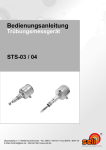
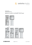

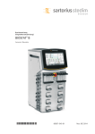
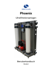
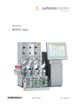
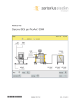
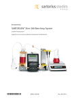


![manual [doc]](http://vs1.manualzilla.com/store/data/006772538_1-1c287c55cb09ceba98cdeeb675cd0306-150x150.png)