1
L
Ä.1qBä
EDK82MV752
.1qB
D
GB
F
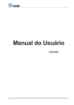
Montageanleitung
Mounting instructions
Instructions de montage
8200 motec
3.0 kW ... 7.5 kW
Lesen Sie zuerst die Montageanleitung, bevor Sie mit den Arbeiten
beginnen!
Beachten Sie die enthaltenen Sicherheitshinweise.
Die Betriebsanleitung mit ausführlicher Information zum
Frequenzumrichter 8200 motec können Sie bei Ihrem
Lenze−Vertriebspartner bestellen.
Read the Mounting Instructions before you start working!
Please observe all safety information given.
Detailed Operating Instructions for the 8200 motec can be ordered directly
from Lenze or Lenze representatives.
Lire attentivement les instructions de montage avant toute opération !
Respecter les consignes de sécurité.
Les instructions de mise en service comprenant une description complète
du convertisseur de fréquence 8200 motec peuvent être commandées
auprès de votre agence Lenze.
8200mot020
8
8200mot021
8
8
8200mot437
8200mot136
18
8200mot465
25
20
8200mot419
8200mot402
22
8200mot441
28
W 2 U 2 V2
U 1 V1 W 1
PE
8200mot142
W 2 U 2 V2
U 1 V1 W 1
PE
8200mot143
L1 / L2 / L3 / N / PE
30
8200mot144
E82MV xxx − x − B (001) 151 − XX 3x 3x
8200 motec
E82MV xxx − x − B 152 (153) − XX 3x 3x
LEERER MERKER
31
X1
K14 K12 K11
-
K14 K12 K11 X1
8200mot145
+
8200mot150
Diese Dokumentation ist gültig für Antriebsregler 8200 motec ab dem Gerätestand
E82MV
Typ
xxx
_
4
302 = 3.0 kW 4 = 400 V
402 = 4.0 kW
552 = 5.5 kW
752 = 7.5 kW
B
xxx
Schaltausgang K1 als ...
001 = ... elektromechanisches Relais
151
152 = ... elektronischer Transistor−Schalter
153
XX
xx
3x
Hard−
warestand
Softwarestand
l
8200mot166
)
Hinweis!
Aktuelle Dokumentationen und Software−Updates zu Lenze Produkten
finden Sie im Internet jeweils im Bereich "Downloads" unter
http://www.Lenze.com
Inbetriebnahme 8200 motec ohne Funktionsmodul
· Der 8200 motec ist nur funktionsfähig mit aufgesteckter FIF−Abdeckkappe ! (Auslieferungszustand).
– Ohne die FIF−Abdeckkappe ist der 8200 motec gesperrt (Keypad: ).
Da der 8200 motec ohne Funktionsmodul keine Steuerklemmen hat, kann das Starten und Stoppen
während des Betriebs auch über Netzschalten erfolgen.
Die Funktion speichert bei Netzschalten oder Betriebsunterbrechungen den Sollwert zum
Zeitpunkt der Unterbrechung. Nach Netzwiederkehr läuft der Antrieb selbsttätig wieder an!
Wenn der Antrieb in Schritt nicht anläuft ( erlischt nicht), drücken, um den 8200 motec
freizugeben.
8200 motec (Geräteausführung mit digitalen Schaltausgang K1) ohne Funktonsmodul benötigen für
den Betrieb dieses Ausgangs eine externe Gleichspannung.
·
·
·
·
E82ZWLxxx
8200mot446
L1 / L2 / L3 / PE
E82ZBB
a e b c d
8 SP h i k f g j
iH
oL
s u
tv
z
x w
y
2
1
d c
j
0140
5000
z
w x
y
vt
88888
AIF
2V 2 U 2 W
1 W 1V 1 U
EP
w
3
Hz
u s
m
888 8888porn q
m
A V zH
C°W hs %
mpr
j
z 0....+50 Hz
8200mot170
Schritt
Handterminal (enthält Keypad) mit motec verbinden. Stecker der Verbindungsleitung in die AIF−Schnittstelle
am motec stecken.
Netzspannung zuschalten.
Selbstanlauf möglich!
Sollwert über die Funktion vorgeben.
y 0....- 50 Hz
Bemerkung
Keypad, Handterminal und Verbindungsleitung sind nicht im Lieferumfang enthalten.
siehe auch
Der Antriebsregler ist nach ca. 1 Sekunde betriebsbereit.
Keypad: aktivieren
Rechtslauf
erlischt. Der Antrieb läuft jetzt.
Linkslauf
Display zeigt Ausgangsfrequenz.
Kapitel 4
Störungen während der Inbetriebnahme oder während des Betriebs?
Kapitel 5
Inhaltsverzeichnis
1
2
3
4
6
Sicherheitshinweise . . . . . . . . . . . . . . . . . . . . . . . . . . . . . . . . . . . . . . . . . . . . . . . . . . .
8
1.1
Allgemeine Sicherheits− und Anwendungshinweise für Lenze−Antriebsregler . . . . . . . . . . . . . . . . . . .
8
1.2
Allgemeine Sicherheits− und Anwenderhinweise für Lenze−Motoren . . . . . . . . . . . . . . . . . . . . . . . . .
10
1.3
Restgefahren . . . . . . . . . . . . . . . . . . . . . . . . . . . . . . . . . . . . . . . . . . . . . . . . . . . . . . . . . . . . . . . . .
13
1.4
Gestaltung der Sicherheitshinweise . . . . . . . . . . . . . . . . . . . . . . . . . . . . . . . . . . . . . . . . . . . . . . . . .
14
Technische Daten . . . . . . . . . . . . . . . . . . . . . . . . . . . . . . . . . . . . . . . . . . . . . . . . . . . . .
15
2.1
Normen und Einsatzbedingungen . . . . . . . . . . . . . . . . . . . . . . . . . . . . . . . . . . . . . . . . . . . . . . . . . .
15
2.2
Bemessungsdaten . . . . . . . . . . . . . . . . . . . . . . . . . . . . . . . . . . . . . . . . . . . . . . . . . . . . . . . . . . . . .
2.2.1
Allgemeine elektrische Daten . . . . . . . . . . . . . . . . . . . . . . . . . . . . . . . . . . . . . . . . . . . . .
2.2.2
Betrieb mit Bemessungsleistung . . . . . . . . . . . . . . . . . . . . . . . . . . . . . . . . . . . . . . . . . .
16
16
16
2.3
Abmessungen . . . . . . . . . . . . . . . . . . . . . . . . . . . . . . . . . . . . . . . . . . . . . . . . . . . . . . . . . . . . . . . .
17
Installation . . . . . . . . . . . . . . . . . . . . . . . . . . . . . . . . . . . . . . . . . . . . . . . . . . . . . . . . . .
18
3.1
motec mit Motor oder Getriebemotor . . . . . . . . . . . . . . . . . . . . . . . . . . . . . . . . . . . . . . . . . . . . . . .
3.1.1
EMV−gerechte Verdrahtung (Aufbau des CE−typischen Antriebssystems) . . . . . . . . . . . . . .
18
19
3.2
Wandmontage . . . . . . . . . . . . . . . . . . . . . . . . . . . . . . . . . . . . . . . . . . . . . . . . . . . . . . . . . . . . . . . .
3.2.1
Lieferumfang . . . . . . . . . . . . . . . . . . . . . . . . . . . . . . . . . . . . . . . . . . . . . . . . . . . . . . . . .
3.2.2
Vorbereitung . . . . . . . . . . . . . . . . . . . . . . . . . . . . . . . . . . . . . . . . . . . . . . . . . . . . . . . . .
3.2.3
Anschluß Motor . . . . . . . . . . . . . . . . . . . . . . . . . . . . . . . . . . . . . . . . . . . . . . . . . . . . . . .
3.2.4
EMV−gerechte Verdrahtung (Aufbau des CE−typischen Antriebssystems) . . . . . . . . . . . . . .
20
20
21
22
23
3.3
Motormontage . . . . . . . . . . . . . . . . . . . . . . . . . . . . . . . . . . . . . . . . . . . . . . . . . . . . . . . . . . . . . . . .
3.3.1
Lieferumfang . . . . . . . . . . . . . . . . . . . . . . . . . . . . . . . . . . . . . . . . . . . . . . . . . . . . . . . . .
3.3.2
Vorbereitung . . . . . . . . . . . . . . . . . . . . . . . . . . . . . . . . . . . . . . . . . . . . . . . . . . . . . . . . .
3.3.3
Anschluß Motor . . . . . . . . . . . . . . . . . . . . . . . . . . . . . . . . . . . . . . . . . . . . . . . . . . . . . . .
3.3.4
EMV−gerechte Verdrahtung (Aufbau des CE−typischen Antriebssystems) . . . . . . . . . . . . . .
25
25
26
28
29
3.4
Elektrischer Anschluß . . . . . . . . . . . . . . . . . . . . . . . . . . . . . . . . . . . . . . . . . . . . . . . . . . . . . . . . . . .
3.4.1
Netzanschluß . . . . . . . . . . . . . . . . . . . . . . . . . . . . . . . . . . . . . . . . . . . . . . . . . . . . . . . .
3.4.2
Anschluß Relais (nur bei Geräteausführungen 001, 151) . . . . . . . . . . . . . . . . . . . . . . . . .
3.4.3
Anschluß Digitaler Schaltausgang (nur bei Geräteausführungen 152, 153) . . . . . . . . . . . .
30
30
31
32
3.5
Montage Funktionsmodule . . . . . . . . . . . . . . . . . . . . . . . . . . . . . . . . . . . . . . . . . . . . . . . . . . . . . . .
34
3.6
motec zusammenbauen . . . . . . . . . . . . . . . . . . . . . . . . . . . . . . . . . . . . . . . . . . . . . . . . . . . . . . . . .
3.6.1
motec mit Funktionsmodulen . . . . . . . . . . . . . . . . . . . . . . . . . . . . . . . . . . . . . . . . . . . . .
3.6.2
motec ohne Funktionsmodule . . . . . . . . . . . . . . . . . . . . . . . . . . . . . . . . . . . . . . . . . . . .
36
36
36
Inbetriebnahme . . . . . . . . . . . . . . . . . . . . . . . . . . . . . . . . . . . . . . . . . . . . . . . . . . . . . . .
37
4.1
Bevor Sie beginnen . . . . . . . . . . . . . . . . . . . . . . . . . . . . . . . . . . . . . . . . . . . . . . . . . . . . . . . . . . . .
37
4.2
Wahl der richtigen Betriebsart . . . . . . . . . . . . . . . . . . . . . . . . . . . . . . . . . . . . . . . . . . . . . . . . . . . . .
38
4.3
Parametrierung mit dem Handterminal E82ZBB . . . . . . . . . . . . . . . . . . . . . . . . . . . . . . . . . . . . . . . .
39
4.4
U/f−Kennliniensteuerung . . . . . . . . . . . . . . . . . . . . . . . . . . . . . . . . . . . . . . . . . . . . . . . . . . . . . . . . .
40
4.5
Vector−Regelung . . . . . . . . . . . . . . . . . . . . . . . . . . . . . . . . . . . . . . . . . . . . . . . . . . . . . . . . . . . . . . .
42
4.6
Wichtige Codes für die schnelle Inbetriebnahme . . . . . . . . . . . . . . . . . . . . . . . . . . . . . . . . . . . . . . .
44
EDK82MV752 DE/EN/FR 6.0
L
Inhaltsverzeichnis
5
Fehlersuche und Störungsbeseitigung . . . . . . . . . . . . . . . . . . . . . . . . . . . . . . . . . . . . .
50
5.1
Fehlverhalten des Antriebs . . . . . . . . . . . . . . . . . . . . . . . . . . . . . . . . . . . . . . . . . . . . . . . . . . . . . . .
50
5.2
LED’s am Antriebsregler (Statusanzeige) . . . . . . . . . . . . . . . . . . . . . . . . . . . . . . . . . . . . . . . . . . . . .
51
5.3
Störungsmeldungen . . . . . . . . . . . . . . . . . . . . . . . . . . . . . . . . . . . . . . . . . . . . . . . . . . . . . . . . . . . .
5.3.1
Störungsmeldungen am Keypad oder im Parametrierprogramm Global Drive Control . . . . .
52
52
L
EDK82MV752 DE/EN/FR 6.0
7
Sicherheitshinweise
Lenze−Antriebsregler
1
Sicherheitshinweise
1.1
Allgemeine Sicherheits− und Anwendungshinweise für
Lenze−Antriebsregler
(gemäß Niederspannungsrichtlinie 73/23/EWG)
Allgemein1
Lenze−Antriebsregler (Frequenzumrichter, Servo−Umrichter, Stromrichter) und zugehörige Komponenten
können während des Betriebs − ihrer Schutzart entsprechend − spannungsführende, auch bewegliche
oder rotierende Teile haben. Oberflächen können heiß sein.
Bei unzulässigem Entfernen der erforderlichen Abdeckung, bei unsachgemäßem Einsatz, bei falscher Installation oder Bedienung besteht die Gefahr von schweren Personen− oder Sachschäden.
Weitere Informationen entnehmen Sie der Dokumentation.
Alle Arbeiten zum Transport, zur Installation, zur Inbetriebnahme und zur Instandhaltung darf nur qualifiziertes Fachpersonal ausführen (IEC 364 bzw. CENELEC HD 384 oder DIN VDE 0100 und IEC−Report 664 oder DIN VDE 0110 und nationale Unfallverhütungsvorschriften beachten).
Qualifiziertes Fachpersonal im Sinne dieser grundsätzlichen Sicherheitshinweise sind Personen, die mit
Aufstellung, Montage, Inbetriebsetzung und Betrieb des Produkts vertraut sind und die über die ihrer Tätigkeit entsprechenden Qualifikationen verfügen.
Bestimmungsgemäße Verwendung
Antriebsregler sind Komponenten, die zum Einbau in elektrische Anlagen oder Maschinen bestimmt sind.
Sie sind keine Haushaltsgeräte, sondern als Komponenten ausschließlich für die Verwendung zur gewerblichen Nutzung bzw. professionellen Nutzung im Sinne der EN 61000−3−2 bestimmt.
Bei Einbau der Antriebsregler in Maschinen ist die Inbetriebnahme (d. h. die Aufnahme des bestimmungsgemäßen Betriebs) solange untersagt, bis festgestellt wurde, dass die Maschine den Bestimmungen der
EG−Richtlinie 98/37/EG (Maschinenrichtlinie) entspricht; EN 60204 beachten.
Die Inbetriebnahme (d. h. die Aufnahme des bestimmungsgemäßen Betriebs) ist nur bei Einhaltung der
EMV−Richtlinie (89/336/EWG) erlaubt.
Die Antriebsregler erfüllen die Anforderungen der Niederspannungsrichtlinie 73/23/EWG. Die harmonisierte Norm EN 61800−5−1 wird für die Antriebsregler angewendet.
Die technischen Daten und die Angaben zu Anschlussbedingungen entnehmen Sie dem Leistungsschild
und der Dokumentation. Halten Sie diese unbedingt ein.
Warnung: Die Antriebsregler sind Produkte, die nach EN 61800−3 in Antriebssysteme der Kategorie C2
eingesetzt werden können. Diese Produkte können im Wohnbereich Funkstörungen verursachen. In diesem Fall kann es für den Betreiber erforderlich sein, entsprechende Maßnahmen durchzuführen.
Transport, Einlagerung
Beachten Sie die Hinweise für Transport, Lagerung und sachgemäße Handhabung.
Halten Sie die klimatischen Bedingungen gemäß den technischen Daten ein.
Aufstellung
Sie müssen die Antriebsregler nach den Vorschriften der zugehörigen Dokumentation aufstellen und kühlen.
Sorgen Sie für sorgfältige Handhabung und vermeiden Sie mechanische Überlastung. Verbiegen Sie bei
Transport und Handhabung weder Bauelemente noch ändern Sie Isolationsabstände. Berühren Sie keine
elektronischen Bauelemente und Kontakte.
Antriebsregler enthalten elektrostatisch gefährdete Bauelemente, die Sie durch unsachgemäße Handhabung leicht beschädigen können. Beschädigen oder zerstören Sie keine elektrischen Komponenten, da
Sie dadurch Ihre Gesundheit gefährden können!
8
EDK82MV752 DE/EN/FR 6.0
L
Sicherheitshinweise
Lenze−Antriebsregler
Elektrischer Anschluss
Beachten Sie bei Arbeiten an unter Spannung stehenden Antriebsreglern die geltenden nationalen Unfallverhütungsvorschriften (z. B. VBG 4).
Führen Sie die elektrische Installation nach den einschlägigen Vorschriften durch (z. B. Leitungsquerschnitte, Absicherungen, Schutzleiteranbindung). Zusätzliche Hinweise enthält die Dokumentation.
Die Dokumentation enthält Hinweise für die EMV−gerechte Installation (Schirmung, Erdung, Anordnung
von Filtern und Verlegung der Leitungen). Beachten Sie diese Hinweise ebenso bei CE−gekennzeichneten
Antriebsreglern. Der Hersteller der Anlage oder Maschine ist verantwortlich für die Einhaltung der im Zusammenhang mit der EMV−Gesetzgebung geforderten Grenzwerte. Um die am Einbauort geltenden
Grenzwerte für Funkstöraussendungen einzuhalten, müssen Sie die Antriebsregler in Gehäuse
(z. B. Schaltschränke) einbauen. Die Gehäuse müssen einen EMV−gerechten Aufbau ermöglichen. Achten Sie besonders darauf, dass z. B. Schaltschranktüren möglichst umlaufend metallisch mit dem Gehäuse verbunden sind. Öffnungen oder Durchbrüche durch das Gehäuse auf ein Minimum reduzieren.
Lenze−Antriebsregler können einen Gleichstrom im Schutzleiter verursachen. Wird für den Schutz bei einer direkten oder indirekten Berührung ein Differenzstromgerät (RCD) verwendet, ist auf der Stromversorgungsseite des Antriebsreglers nur ein Differenzstromgerät (RCD) vom Typ B zulässig. Anderenfalls muss
eine andere Schutzmaßnahme angewendet werden, wie z. B. Trennung von der Umgebung durch doppelte oder verstärkte Isolierung oder Trennung vom Versorgungsnetz durch einen Transformator.
Betrieb
Sie müssen Anlagen mit eingebauten Antriebsreglern ggf. mit zusätzlichen Überwachungs− und Schutzeinrichtungen gemäß den jeweils gültigen Sicherheitsbestimmungen ausrüsten (z. B. Gesetz über technische Arbeitsmittel, Unfallverhütungsvorschriften). Sie dürfen die Antriebsregler an Ihre Anwendung anpassen. Beachten Sie dazu die Hinweise in der Dokumentation.
Nachdem der Antriebsregler von der Versorgungsspannung getrennt ist, dürfen Sie spannungsführende
Geräteteile und Leistungsanschlüsse nicht sofort berühren, weil Kondensatoren aufgeladen sein können.
Beachten Sie dazu die entsprechenden Hinweisschilder auf dem Antriebsregler.
Halten Sie während des Betriebs alle Schutzabdeckungen und Türen geschlossen.
Hinweis für UL−approbierte Anlagen mit eingebauten Antriebsreglern: UL warnings sind Hinweise,
die nur für UL−Anlagen gelten. Die Dokumentation enthält spezielle Hinweise zu UL.
Sicherheitsfunktionen2
Bestimmte Varianten der Antriebsregler unterstützen Sicherheitsfunktionen (z. B. "Sicher abgeschaltetes
Moment", ehem. "Sicherer Halt") nach den Anforderungen von Anhang I Nr. 1.2.7 der EG−Richtlinie "Maschinen" 98/37/EG, EN 954−1 Kategorie 3 und EN 1037. Beachten Sie unbedingt die Hinweise zu den Sicherheitsfunktionen in der Dokumentation zu den Varianten.
Wartung und Instandhaltung
Die Antriebsregler sind wartungsfrei, wenn die vorgeschriebenen Einsatzbedingungen eingehalten werden.
Bei verunreinigter Umgebungsluft können die Kühlflächen des Antriebsreglers verschmutzen oder Kühlöffnungen verstopft werden. Bei diesen Betriebsbedingungen deshalb regelmäßig die Kühlflächen und
Kühlöffnungen reinigen. Dazu niemals scharfe oder spitze Gegenstände verwenden!
Entsorgung
Metalle und Kunststoffe zur Wiederverwertung geben. Bestückte Leiterplatten fachgerecht entsorgen.
Beachten Sie unbedingt die produktspezifischen Sicherheits− und Anwendungshinweise in dieser
Anleitung!
L
EDK82MV752 DE/EN/FR 6.0
9
Sicherheitshinweise
Lenze−Niederspannungsmaschinen
1.2
Allgemeine Sicherheits− und Anwenderhinweise für
Lenze−Motoren
(gemäß Niederspannungsrichtlinie 73/23/EWG)
Allgemein
Niederspannungsmaschinen haben gefährliche, spannungsführende und rotierende Teile sowie
möglicherweise heiße Oberflächen.
Bei Synchronmaschinen werden bei drehender Maschine auch an den offenen Klemmen Spannungen induziert.
Alle Arbeiten zu Transport, Anschluss, Inbetriebnahme und Instandhaltung darf nur qualifiziertes,
verantwortliches Fachpersonal ausführen (EN 50110−1 (VDE 0105−100) und IEC 60364 beachten).
Unsachgemäßes Verhalten kann schwere Personen− und Sachschäden verursachen.
Niederspannungsmaschinen nur unter den Einsatzzwecken betreiben, die im Abschnitt "Bestimmungsgemäße Verwendung" angegeben sind.
Die Bedingungen am Einsatzort müssen allen Angaben entsprechen, die auf dem Leistungsschild
und in der Dokumentation genannt sind.
Bestimmungsgemäße Verwendung
Niederspannungsmaschinen sind für gewerbliche Anlagen bestimmt. Sie entsprechen den harmonisierten Normen der Reihe EN60034 (VDE 0530). Der Einsatz im Ex−Bereich ist verboten, sofern
nicht ausdrücklich hierfür vorgesehen (Zusatzhinweise beachten).
Niederspannungsmaschinen sind Komponenten zum Einbau in Maschinen im Sinne der Maschinenrichtlinie 98/37/EG. Die Inbetriebnahme ist solange untersagt, bis die Konformität des Endprodukts mit dieser Richtlinie festgestellt ist (u. a. EN 60204−1 beachten).
Niederspannungsmaschinen in Schutzart IP23 oder geringer nicht ohne besondere Schutzmaßnahmen im Freien verwenden.
Die eingebauten Bremsen nicht als Sicherheitsbremsen verwenden. Es ist nicht auszuschließen,
dass durch nicht zu beeinflussende Störfaktoren, z. B. Öleintritt durch Versagen des A−seitigen Wellendichtrings, das Brems−Drehmoment reduziert sein kann.
Transport, Einlagerung
Nach der Auslieferung festgestellte Beschädigungen dem Transportunternehmen sofort mitteilen;
die Inbetriebnahme ist ggf. auszuschließen. Eingeschraubte Transportösen fest anziehen. Sie sind
für das Gewicht der Niederspannungsmaschine ausgelegt, keine zusätzlichen Lasten anbringen.
Wenn notwendig, ausreichend bemessene Transportmittel (z. B. Seilführungen) verwenden.
Vorhandene Transportsicherungen vor Inbetriebnahme entfernen. Für weitere Transporte erneut
verwenden. Werden Niederspannungsmaschinen eingelagert, auf eine trockene, staubfreie und
schwingungsarme (veff £ 0.2 mm/s) Umgebung achten (Lagerstillstandsschäden).
10
EDK82MV752 DE/EN/FR 6.0
L
Sicherheitshinweise
Lenze−Niederspannungsmaschinen
Aufstellung
Auf plane Auflage, gute Fuß− bzw. Flanschbefestigung und genaue Ausrichtung bei direkter Kupplung achten. Aufbaubedingte Resonanzen mit der Drehfrequenz und der doppelten Speisefrequenz
vermeiden. Läufer von Hand drehen, auf ungewöhnliche Schleifgeräusche achten. Drehrichtung im
ungekuppelten Zustand kontrollieren (Abschnitt "Elektrischer Anschluss" beachten).
Riemenscheiben und Kupplungen nur mit geeigneten Vorrichtungen aufziehen oder abziehen. Zur
leichteren Handhabung vorher erwärmen. Riemenscheiben und Kupplungen mit einem Berührschutz abdecken. Unzulässige Riemenspannungen vermeiden.
Die Maschinen sind mit halber Passfeder gewuchtet. Die Kupplung muss ebenfalls mit halber Passfeder gewuchtet sein. Überstehenden, sichtbaren Passfederanteil abarbeiten.
Eventuell erforderliche Rohranschlüsse herstellen. Bauformen mit Wellenende nach unten bauseits
mit einer Abdeckung ausrüsten, die verhindert, dass Fremdkörper in den Lüfter hineinfallen. Die Belüftung darf nicht behindert werden und die Abluft − auch benachbarter Aggregate − nicht unmittelbar
wieder angesaugt werden.
Elektrischer Anschluss
Alle Arbeiten dürfen nur von qualifiziertem Fachpersonal an der stillstehenden Niederspannungsmaschine im freigeschalteten und gegen Wiedereinschalten gesicherten Zustand vorgenommen
werden. Das gilt auch für Hilfsstromkreise (z. B. Bremse, Geber, Fremdlüfter).
Spannungsfreiheit prüfen!
Überschreiten der Toleranzen in EN 60034−1; IEC 34 (VDE 0530−1) − Spannung ±5 %, Frequenz
±2 %, Kurvenform, Symmetrie − erhöht die Erwärmung und beeinflusst die elektromagnetische Verträglichkeit.
Schaltungshinweise, Angaben auf dem Leistungsschild und Anschlussschema im Klemmenkasten
beachten.
Der Anschluss muss so erfolgen, dass eine dauerhaft sichere, elektrische Verbindung aufrecht erhalten wird (keine abstehenden Drahtenden); zugeordnete Kabelendbestückung verwenden. Sichere Schutzleiterverbindung herstellen. Steckverbinder bis zum Anschlag festschrauben.
Die kleinsten Luftabstände zwischen blanken, spannungsführenden Teilen und gegen Erde dürfen
folgende Werte nicht unterschreiten: 8 mm bei UN £ 550 V, 10 mm bei UN £ 725 V, 14 mm bei
UN £ 1000 V.
Der Klemmenkasten muss frei sein von Fremdkörpern, Schmutz und Feuchtigkeit. Nicht benötigte
Kabeleinführungsöffnungen und den Klemmenkasten staubdicht und wasserdicht verschließen.
L
EDK82MV752 DE/EN/FR 6.0
11
Sicherheitshinweise
Lenze−Niederspannungsmaschinen
Inbetriebnahme und Betrieb
Vor Inbetriebnahme nach längerer Lagerzeit den Isolationswiderstand messen. Bei Werten £ 1 kW
je Volt Bemessungsspannung die Wicklung trocknen.
Für den Probebetrieb ohne Abtriebselemente die Passfeder sichern. Schutzeinrichtungen auch im
Probebetrieb nicht außer Funktion setzen.
Bei Niederspannungsmaschinen mit Bremse vor der Inbetriebnahme die einwandfreie Funktion der
Bremse prüfen.
Eingebaute Temperaturfühler sind kein Vollschutz der Maschine, ggf. Maximalstrom begrenzen. Antriebsregler so parametrieren, dass nach einigen Sekunden Betrieb mit I > IN der Motor abgeschaltet wird, insbesondere bei Gefahr des Blockierens.
Schwingstärken veff £ 3.5 mm/s (PN £ 15 kW) bzw. 4.5 mm/s (PN > 15 kW) sind in gekuppeltem Betrieb unbedenklich.
Bei Veränderungen gegenüber dem Normalbetrieb, z. B. erhöhte Temperaturen, Geräusche,
Schwingungen, die Ursache ermitteln, ggf. Rücksprache mit dem Hersteller. Im Zweifelsfall Niederspannungsmaschine abschalten.
Bei starkem Schmutzanfall Luftwege regelmäßig reinigen.
Wellendichtringe und Wälzlager haben eine begrenzte Lebensdauer.
Lagerungen mit Nachschmiereinrichtung bei laufender Niederspannungsmaschine nachfetten. Nur
vom Hersteller freigegebene Fette verwenden. Wenn Fettaustrittsbohrungen mit Stopfen verschlossen sind (IP54 Abtriebsseite; IP23 Abtriebs−und Nichtabtriebsseite), vor Inbetriebnahme Stopfen
entfernen. Bohrungen mit Fett verschließen. Lagerwechsel bei Dauerschmierung (2Z−Lager) nach
ca. 10.000 h − 20.000 h, spätestens jedoch nach 3 − 4 Jahren.
Beachten Sie die produktspezifischen Sicherheits− und Anwendungshinweise in
dieser Anleitung!
12
EDK82MV752 DE/EN/FR 6.0
L
Sicherheitshinweise
Restgefahren, Gestaltung der Sicherheitshinweise
1.3
Restgefahren
Personenschutz
l
Schalten Sie vor Arbeitsbeginn / Öffnen des Gerätes den Antriebsregler spannungslos und
warten Sie mindestens 1 Minute, da nach dem Netzabschalten die Leistungsklemmen
U, V, W; BR0, BR1, BR2 und die Pins der Schnittstelle FIF gefährliche Spannung führen.
– Überprüfen Sie nach dem Öffnen des motec, ob die Leistungsklemmen L1, L2, L3; U, V, W;
BR0, BR1, BR2, die Relaisausgänge K11, K12, K14 bzw. der elektronische Schaltausgang
K12 (bei Geräteausführung 001 oder 151 bzw. 152 oder 153) und die Pins der Schnittstelle
FIF spannungslos sind.
– Auch bei vom Netz getrenntem Antriebsregler können die Relaisausgänge K11, K12, K14
bzw. der elektronische Schaltausgang K12 (bei Geräteausführung 001 oder 151 bzw. 152
oder 153) gefährliche Spannung führen!
l
Wenn Sie die nicht drahtbruchsichere Funktion Drehrichtungsvorgabe" über das digitale
Signal DCTRL1−CW/CCW verwenden (C0007 = −0− ... −13−, C0410/3 ¹ 255):
– Bei Drahtbruch oder bei Ausfall der Steuerspannung kann der Antrieb die Drehrichtung
wechseln.
l
Wenn Sie die Funktion "Fangschaltung" (C0142 = −2−, −3−) bei Maschinen mit geringem
Massenträgheitsmoment und geringer Reibung verwenden:
– Nach Reglerfreigabe im Stillstand kann der Motor kurzzeitig anlaufen oder kurzzeitig die
Drehrichtung wechseln.
l
Der Kühlkörper des motec hat eine Betriebstemperatur > 60 °C:
– Hautkontakt mit dem Kühlkörper führt zu Verbrennungen.
Motorschutz
l
Bei bestimmten Einstellungen der Antriebsregler kann der angeschlossene Motor überhitzt
werden:
– Z. B. längerer Betrieb der Gleichstrombremse.
– Längerer Betrieb eigenbelüfteter Motoren bei kleinen Drehzahlen.
Geräteschutz
l
8200 motec 3 ... 7,5 kW (E82MV302_4B, E82MV402_4B, E82MV552_4B, E82MV752_4B):
– Häufiges Netzschalten (z. B. Tipp−Betrieb über Netzschütz) kann die
Eingangsstrombegrenzung des Antriebsreglers überlasten und zerstören:
– Deshalb müssen zwischen zwei Einschaltvorgängen mindestens drei Minuten vergehen.
– Die Lüfterüberwachung muß unbedingt bei der Inbetriebnahme über die Codestelle C0608
aktiviert werden. Der Antriebsregler kann sonst durch Überhitzung zerstört werden.
Schutz der Maschine/Anlage
l
L
Antriebe können gefährliche Überdrehzahlen erreichen (z. B. Einstellung hoher
Ausgangsfrequenzen bei dafür ungeeigneten Motoren und Maschinen):
– Die Antriebsregler bieten keinen Schutz gegen solche Betriebsbedingungen. Setzen Sie
dafür zusätzliche Komponenten ein.
EDK82MV752 DE/EN/FR 6.0
13
Sicherheitshinweise
Restgefahren, Gestaltung der Sicherheitshinweise
Warnings!
l The device has no overspeed protection.
l Must be provided with external or remote overload protection.
l Suitable for use on a circuit capable of delivering not more than 5000 rms
symmetrical amperes, 240 V maximum (240 V devices) or 500 V maximum
(400/500 V devices) resp.
l Circuit breakers (either inverse−time or instantaneous trip types) may be used in
lieu of above fuses when it is shown that the let−through energy (I2t) and peak
let−through current (Ip) of the inverse−time current−limiting circuit breaker will be
less than that of the non−semiconductor type K5 fuses with which the drive has
been tested. An inverse−time circuit breaker may be used, sized upon the input
rating of the drive, multiplied by 300 %.
l Use 60/75 °C or 75 °C copper wire only.
l If mounted on a motor the environmental rating tests for Type 4 and Type 12 shall
be performed.
1.4
Gestaltung der Sicherheitshinweise
Alle Sicherheitshinweise in dieser Anleitung sind einheitlich aufgebaut:
}
Piktogramm (kennzeichnet die Art der Gefahr)
Signalwort! (kennzeichnet die Schwere der Gefahr)
Hinweistext (beschreibt die Gefahr und gibt Hinweise, wie sie vermieden werden
kann)
Piktogramm
gefährliche elektrische Spannung
Signalwort
Signalwort
Gefahr!
Bedeutung
Unmittelbar drohende Gefahr für Personen
Warnung!
Mögliche, sehr gefährliche Situation für
Personen
Tod oder schwerste Verletzungen
Vorsicht!
Mögliche, gefährliche Situation für Personen
Leichte Verletzungen
Mögliche Sachschäden
Beschädigung des Antriebssystems
oder seiner Umgebung
allgemeine Gefahr
14
Folgen bei Mißachtung der
Sicherheitshinweise
Stop!
Hinweis!
Tod oder schwerste Verletzungen
Nützlicher Hinweis oder Tipp
Wenn Sie ihn befolgen, erleichtern Sie sich
die Handhabung des Antriebssystems.
EDK82MV752 DE/EN/FR 6.0
L
Technische Daten
Normen und Einsatzbedingungen
2
Technische Daten
2.1
Normen und Einsatzbedingungen
Konformität
Approbationen
CE
UL 508C
Rüttelfestigkeit
Klimatische Bedingungen
Lagerung
Transport
Betrieb
IEC/EN 60721−3−1
IEC/EN 60721−3−2
IEC/EN 60721−3−3
Zulässige Aufstellungshöhe
Einbaulagen
Einbaufreiräume motec
Einbaufreiräume Lüfterbaugruppe E82ZMV
Betrieb mit Lüfterbaugruppe
E82ZMV
L
Niederspannungsrichtlinie (73/23/EWG)
Underwriter Laboratories (File−No. E132659)
Power Conversion Equipment
Beschleunigungsfest bis 2g (Germanischer Lloyd, allgemeine Bedingungen)
1K3 (−25 °C...+60 °C)
2K3 (−25 °C...+70 °C)
3K3 (−20 °C...+60 °C)
über +40 °C Ausgangs−Bemessungsstrom um 2,5 %/°C reduzieren
0 ... 4000 m üNN
über 1000 m üNN Ausgangs−Bemessungsstrom um 5 %/1000 m reduzieren
Jede Einbaulage und Einbau−Ausrichtung zulässig
oberhalb
100 mm
seitlich
100 mm
für Lüfterwechsel
250 mm
Die Lüfterbaugruppe E82ZMV muß immer eingesetzt werden bei
· Wandmontage des motec
· Betrieb ohne Stromreduzierung mit eigenbelüfteten Lenze−Motoren oder Lenze−Getriebmotoren 16
· Betrieb mit Fremdmotor
EDK82MV752 DE/EN/FR 6.0
15
Technische Daten
Bemessungsdaten
2.2
Bemessungsdaten
2.2.1
Allgemeine elektrische Daten
EMV
Störaussendung
Einhaltung der Anforderungen nach EN 61800−3/A11
Motormontage
Einhaltung der Grenzwertklassen A und B nach EN 55011
Wandmontage
Einhaltung der Grenzwertklasse A nach EN 55011
(bis 10 m geschirmte Motorleitung)
Einhaltung der Grenzwertklasse B nach EN 55011
(bis 1 m geschirmte Motorleitung)
Schutzart
IP55 (NEMA 250 Typ 12) ohne Schutzkappe auf der AIF−Schnittstelle
IP65 (NEMA 250 Typ 4) mit Schutzkappe auf der AIF−Schnittstelle
Schutzmaßnahmen gegen
Kurzschluß, Erdschluß (erdschlußfest im Betrieb, eingeschränkt erdschlußfest beim Netzeinschalten), Überspannung, Kippen des Motors, Motor−Übertemperatur (Eingang für PTC oder Thermokontakt, I2t−Überwachung)
Schutzisolierung von Steuer- Sichere Trennung vom Netz:
schaltkreisen
Doppelte/verstärkte Isolierung nach EN 61800−5−1
2.2.2
Betrieb mit Bemessungsleistung
typische Motorleistung
8200 motec
Netzspannungsbereich
Daten für Betrieb an 3 PE AC
Netz−Bemessungsstrom
Ausgangsstrom 1)
8 kHz 2)
Max. zulässiger Ausgangsstrom für
8 kHz
60 s
Gewicht
mit Lüfterbaugruppe E82ZMV
1)
PN [kW]
PN [hp]
Typ
UN [V]
IN [A]
IN8 [A]
INmax8 [A]
3.0
4.0
5.5
7.5
4.1
5.4
7.5
10.2
E82MV302_4B
E82MV402_4B
E82MV552_4B
E82MV752_4B
3 PE AC 320 V −0 % ... 550 V +0 % (45 Hz −0 % ... 65 Hz +0 %)
400 V
400 V
400 V
400 V
9.5
12.3
16.8
21.4
7.3
9.5
13.0
16.5
11.0
14.2
19.5
24.8
m [kg]
m [kg]
9,7
11,1
9,7
11,1
9,7
11,1
9,7
11,1
Die Ströme gelten für den Betrieb mit Lüfterbaugruppe E82ZMV oder mit fremdbelüfteten Lenze−Motoren/Getriebemotoren
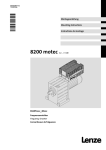
Bei Betrieb mit eigenbelüfteten Lenze−Motoren/Getriebemotoren mus der Ausgangs−Bemessungstrom reduziert werden (siehe Abb. 1)
Schaltfrequenz des Wechselrichters
2)
Stromreduzierung bei Betrieb ohne Lüfterbaugruppe E82ZMV mit eigenbelüftetem Lenze−Motor oder Lenze−Getriebemotror
I/I
Die Angaben gelten für Dauerbetrieb bei
· Schaltfrequenz 4 kHz und Umgebungstemperatur 40 °C
1
· Schaltfrequenz 8 kHz und Umgebungstemperatur 35 °C
N
0,8
0,7
0,6
0,5
0,4
4B
2_
30
MV
B
_4
02
V4
M
2
B
E8
_4
52
V5
M
2
E8
2
E8
E8
2M
V7
52
_4
B
0,9
I
Reduzierter Ausgangsstrom [A] 8200 motec
Ir
Ausgangs−Bemessungsstrom [A] 8200 motec bei Schaltfrequenz
4 kHz bzw. 8 kHz
f
Ausgangsfrequenz 8200 motec
0,3
0,2
0,1
10
20
30
40
50
f [Hz]
8200mot339
Abb. 1
16
Reduzierung des Ausgangs−Bemessungsstroms
EDK82MV752 DE/EN/FR 6.0
L
Technische Daten
Abmessungen, mechanische Ausführung
2.3
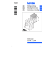
Abmessungen
82mot443
Abb. 2
Abmessungen motec
Typ
E82MV302_4B
E82MV402_4B
E82MV552_4B
E82MV752_4B
1)
a
b
c
d
e
[mm]
[mm]
[mm]
[mm]
[mm]
211
163
223 1)
148
325
15
Gewicht
Verschraubungen
[kg]
3 × M25, 4 × M16
(Gewindelänge 10 mm, ohne Gegenmutter)
9.7
mit Lüfterbaugruppe E82ZMV
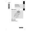
16
140
56
206
206
180
172
60
56
5.5
60
320
82mot460
Abb. 3
L
Abmessungen Lüfterbaugruppe E82ZMV
EDK82MV752 DE/EN/FR 6.0
17
Installation
motec mit Motor oder Getriebemotor
3
Installation
3.1
motec mit Motor oder Getriebemotor
30
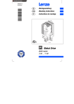
8200mot448
Abb. 4
18
Vorbereitung für den elektrischen Anschluß
EDK82MV752 DE/EN/FR 6.0
L
Installation
motec mit Motor oder Getriebemotor
3.1.1
EMV−gerechte Verdrahtung (Aufbau des CE−typischen Antriebssystems)
Bedingungen für störungsfreien Betrieb:
l
Mit Ausnahme der Netzleitung nur geschirmte Leitungen verwenden.
l
Schirmung sorgfältig auf PE legen (siehe unten).
l
Motor− und Netz−Schutzleiter an getrennte PE−Klemmen schrauben.
A
B
Schirmauflage:
1. Leitung vorbereiten
B
X1
2. Kabelbinder einlegen
I
C
G
F
H
3. Leitung einlegen und
Kabelbinder anziehen.
Die Abschirmung muß
fest mit dem Schirmblech verbunden sein.
D
X2
E
E
E
82mot396
82mot395
Abb. 5
EMV−gerechte Verdrahtung
Anschlußleitung für Relais1 oder elektronischen Schaltausgang 2
Netzleitungen L1, L2, L3, PE (2 Leitungen zum Netz durchschleifen)
PE−Anschluß Netzleitungen
Geschirmte Steuerleitungen; Schirm mit Kabelbinder fest auf
dem Blech fixieren
Geschirmte Steuerleitungen
Potentialfreie Klemme (z.B. Sternpunkt bei Sternschaltung des
Motors)
X1 Klemmenleiste Netzanschluß
X2 Klemmenleiste Motoranschluß
PES HF−Schirmanschluß durch PE−Anbindung über Schirmauflage
FIF−Halterung
Funktionsmodul Bus−I/O auf Steckplatz 1
Feldbus−Funktionsmodul auf Steckplatz 2
1) gilt für Geräteausführung 001 und 151
2) gilt für Geräteausführungen 152 und 153
L
EDK82MV752 DE/EN/FR 6.0
19
Installation
Wandmontage
3.2
Wandmontage
3.2.1
Lieferumfang
8200mot449
Abb. 6
Lieferumfang motec für Wandmontage
20
8200 motec (Elektronikmodul und Trägergehäuse)
Adapterplatte
Flachdichtungen für Adapterplatte (bei Wandmontage nicht benötigt)
Halterung für Funktionsmodule und elektrischen Anschluß der Lüfterbaugruppe
Lüfterbaugruppe E82ZMV
4 Schrauben M5 × 65 mm zur Befestigung des Trägergehäuses auf der Lüfterbaugruppe
EDK82MV752 DE/EN/FR 6.0
L
Installation
Wandmontage
3.2.2
Vorbereitung
(
Stop!
Der motec kann durch thermische Überlastung zerstört werden!
Bei der Wandmontage müssen Sie zusätzlich die Lüfterbaugruppe E82ZMV
montieren, um eine ausreichende Kühlung des motec zu gewährleisten.
8200mot402
Abb. 7
motec an die Wand montieren
1. Adapterplatte vormontieren:
– Adapterplatte mit zwei Schrauben M5 x 65 in die Aufnahmen an der Lüfterbaugruppe ziehen
– Schrauben wieder entfernen
2. Lüfterbaugruppe mit geeigneten Schrauben an der Wand befestigen
3. Am Trägergehäuse Kabeldurchführungen festlegen und die Öffnungen herausbrechen
4. Verschraubungen einsetzen
5. Trägergehäuse auf Lüfterbaugruppe setzen und mit 4 Schrauben M5 x 65 mm (Lieferumfang)
auf die Lüfterbaugruppe schrauben
6. Leitungen, die in das Trägergehäuse geführt werden, abisolieren. Für alle geschirmten
Leitungen gilt:
– Kabelmantel 10 cm abisolieren
– Schirmung der Leitungsadern auf 8 cm Länge entfernen
– 2 cm des Schirms werden für die sichere Schirmauflage benötigt
L
EDK82MV752 DE/EN/FR 6.0
21
Installation
Wandmontage
3.2.3
Anschluß Motor
Gefahr!
l
l
Alle Steuerklemmen sind nach dem Anschluß eines Kaltleiters (PTC) oder eines
Thermokontakts nur noch basisisoliert (einfache Trennstrecke).
Berührsicherheit bei defekter Trennstrecke ist nur durch externe Maßnahmen
gewährleistet, z. B. doppelte Isolierung.
30
8200mot468
Abb. 8
Anschluß des Motors bei Wandmontage
Kapazitätsarme Motorleitungen verwenden! (Ader/Ader £ 75 pF/m, Ader/Schirm £ 150 pF/m)
Möglichst kurze Motorleitungen wirken sich positiv auf das Antriebsverhalten aus!
PES
HF−Schirmabschluß durch großflächige Anbindung an PE
X2/PE2
Klemme nicht verwenden
X2/BR1, X2/BR2
Anschlußklemmen Bremswiderstand
(Informationen zum Betrieb mit Bremswiderstand: siehe Betriebsanleitung)
X2/T1, X2/T2
Anschlußklemmen Motortemperatur−Überwachung mit Kaltleiter (PTC) oder Thermokontakt
Motortemperatur−Überwachung mit C0119 aktivieren (z. B. C0119 = 1)!
Leitungsquerschnitte U, V, W, PE
Typ
E82MV302_4B
E82MV402_4B
E82MV552_4B
E82MV752_4B
22
mm2
1
1.5
2.5
4
EDK82MV752 DE/EN/FR 6.0
AWG
16
14
12
10
L
Installation
Wandmontage
3.2.4
EMV−gerechte Verdrahtung (Aufbau des CE−typischen Antriebssystems)
Bedingungen für störungsfreien Betrieb:
l
Außer der Netzleitung nur geschirmte Leitungen verwenden.
l
Schirmung sorgfältig auf PE legen (siehe unten).
l
Steuer− und Netzleitung räumlich getrennt von Motorleitung verlegen!
l
Motor− und Netz−Schutzleiter an getrennte PE−Klemmen schrauben.
Schirmauflage:
1. Leitung vorbereiten
A
B
B
X1
2. Kabelbinder einlegen
K
C
I
H
D
E
J
3. Leitung einlegen und
Kabelbinder anziehen.
Die Abschirmung muß
fest mit dem Schirmblech verbunden sein.
X2
F
F
F
G
82mot398
Abb. 9
82mot397
EMV−gerechte Verdrahtung
Relais−Anschlußleitung
Netzleitungen L1, L2, L3, PE (2 Leitungen zum Netz durchschlei- fen)
PE−Anschluß Netzleitungen
Geschirmte Steuerleitungen; Schirm mit Kabelbinder fest auf
dem Blech fixieren
PE−Anschluß Motorleitung
Geschirmte Steuerleitungen
Motorleitung U, V, W (kapazitätsarme Motorleitungen verwenden!
22)
Potentialfreie Klemme (z. B. Sternpunkt bei Sternschaltung des
Motors)
X1 Klemmenleiste Netzanschluß
X2 Klemmenleiste Motoranschluß
PES HF−Schirmabschluß durch großflächige Anbindung an PE
L
FIF−Halterung
Funktionsmodul Bus−I/O auf Steckplatz 1
Feldbus−Funktionsmodul auf Steckplatz 2
EDK82MV752 DE/EN/FR 6.0
23
Installation
Wandmontage
24
EDK82MV752 DE/EN/FR 6.0
L
Installation
Motormontage
3.3
Motormontage
3.3.1
Lieferumfang
8200mot449
Abb. 10
Lieferumfang motec für Motormontage
L
8200 motec (Elektronikmodul und Trägergehäuse)
Adapterplatte
Flachdichtungen für Adapterplatte
Halterung für Funktionsmodule und elektrischen Anschluß der Lüfterbaugruppe
Lüfterbaugruppe E82ZMV
4 Schrauben M5 × 65 mm zur Befestigung des Trägergehäuses auf der Lüfterbaugruppe
EDK82MV752 DE/EN/FR 6.0
25
Installation
Motormontage
3.3.2
Vorbereitung
(
Stop!
l
l
Wenn Sie keinen Lenze−Motor/Getriebemotor einsetzen, müssen Sie zusätzlich
die Lüfterbaugruppe E82ZMV montieren, um eine ausreichende Kühlung des
motec zu gewährleisten.
Wenn Sie einen eigenbelüfteten Lenze−Motor/Getriebemotor und keine
Lüfterbaugruppe einsetzen, ist der Betrieb des motec nur mit reduziertem
Ausgangsstrom zulässig. ( 16)
8200mot453
Abb. 11
26
motec auf den Motor montieren
EDK82MV752 DE/EN/FR 6.0
L
Installation
Motormontage
1. Klemmenkasten des Motors entfernen
– Bei beengten Platzverhältnissen auch das Klemmenbrett des Motors entfernen.
2. Motoranschlußdrähte für die Verbindung von Klemmbrett zu Klemme X2 mit dem Klemmbrett
verbinden
– Leitungslänge 20 cm
3. Am Trägergehäuse Kabeldurchführungen festlegen und die Öffnungen herausbrechen
4. Verschraubungen einsetzen
5. Klemmenkastendichtung einlegen
6. Flachdichtungen in die Langlöcher der Adapterplatte einlegen
7. Adapterplatte mit geeigneten Schrauben auf den Motor schrauben
8. Kabeldurchführung in der Lüfterbaugruppe herausbrechen
9. Lüfterbaugruppe auf Adapterplatte setzen
10.Trägergehäuse auf Lüfterbaugruppe setzen und mit 4 Schrauben M5 x 65 mm (Lieferumfang)
auf die Lüfterbaugruppe schrauben
11.Leitungen, die in das Trägergehäuse geführt werden, abisolieren. Für alle geschirmten
Leitungen gilt:
– Kabelmantel 10 cm abisolieren
– Schirmung der Leitungsadern auf 8 cm Länge entfernen
– 2 cm des Schirms werden für die sichere Schirmauflage benötigt
L
EDK82MV752 DE/EN/FR 6.0
27
Installation
Motormontage
3.3.3
Anschluß Motor
Gefahr!
l
l
Alle Steuerklemmen sind nach dem Anschluß eines Kaltleiters (PTC) oder eines
Thermokontakts nur noch basisisoliert (einfache Trennstrecke).
Berührsicherheit bei defekter Trennstrecke ist nur durch externe Maßnahmen
gewährleistet, z. B. doppelte Isolierung.
30
8200mot408
Abb. 12
28
Anschluß des Motors bei Motormontage
X2/PE2
Klemme nicht verwenden
X2/BR1, X2/BR2
Anschlußklemmen Bremswiderstand
(Informationen zum Betrieb mit Bremswiderstand: siehe Betriebsanleitung)
X2/T1, X2/T2
Anschlußklemmen Motortemperatur−Überwachung mit Kaltleiter (PTC) oder Thermokontakt
Motortemperatur−Überwachung mit C0119 aktivieren (z. B. C0119 = 1)!
EDK82MV752 DE/EN/FR 6.0
L
Installation
Motormontage
3.3.4
EMV−gerechte Verdrahtung (Aufbau des CE−typischen Antriebssystems)
Bedingungen für störungsfreien Betrieb:
l
Mit Ausnahme der Netzleitung nur geschirmte Leitungen verwenden.
l
Schirmung sorgfältig auf PE legen (siehe unten).
l
Motor− und Netz−Schutzleiter an getrennte PE−Klemmen schrauben.
A
B
Schirmauflage:
1. Leitung vorbereiten
B
X1
2. Kabelbinder einlegen
J
C
H
G
D
I
3. Leitung einlegen und
Kabelbinder anziehen.
Die Abschirmung muß
fest mit dem Schirmblech verbunden sein.
E
X2
F
F
F
82mot396
82mot395
Abb. 13
EMV−gerechte Verdrahtung
Relais−Anschlußleitung
Netzleitungen L1, L2, L3, PE (2 Leitungen zum Netz durchschleifen)
PE−Anschluß Netzleitungen
Geschirmte Steuerleitungen; Schirm mit Kabelbinder fest auf
dem Blech fixieren
PE−Anschluß Motorleitung
Geschirmte Steuerleitungen
Potentialfreie Klemme (z. B. Sternpunkt bei Sternschaltung des
Motors)
X1 Klemmenleiste Netzanschluß
X2 Klemmenleiste Motoranschluß
PES HF−Schirmabschluß durch großflächige Anbindung an PE
L
FIF−Halterung
Funktionsmodul Bus−I/O auf Steckplatz 1
Feldbus−Funktionsmodul auf Steckplatz 2
EDK82MV752 DE/EN/FR 6.0
29
Installation
Elektrischer Anschluß
3.4
Elektrischer Anschluß
3.4.1
Netzanschluß
Gefahr!
Gefährliche elektrische Spannung
Der Ableitstrom gegen Erde (PE) ist > 3,5 mA AC.
Mögliche Folgen:
l Tod oder schwere Verletzungen beim Berühren des Gerätes im Fehlerfall.
Schutzmaßnahmen:
l Die in der EN 61800−5−1 geforderten Maßnahmen umsetzen. Insbesondere:
– Festinstallation
– PE−Anschluss normgerecht ausführen (PE−Leiterdurchmesser ³ 10 mm2 (Cu)
oder PE−Leiter doppelt auflegen)
31
8200mot409
Abb. 14
30
Netzleitung anschließen
EDK82MV752 DE/EN/FR 6.0
L
Installation
Elektrischer Anschluß
3.4.1.1
Sicherungen und Leitungsquerschnitte
Typ
E82MV302_4B
3/PE AC
E82MV402_4B
320 ... 550 V;
E82MV552_4B
45 ... 65 Hz
E82MV752_4B
Installation nach UL 1)
Installation nach EN 60204−1
Netz
Schmelzsicherung
Sicherungsautomat
L1, L2, L3, PE
[mm2]
Schmelzsicherung
L1, L2, L3, PE
[AWG]
M16 A
M20 A
M25 A
M32 A
B16 A
B20 A
B25 A
B32 A
2.5
4.0
4.0
6.0
15 A
20 A
25 A
35 A
14
12
10
8
1)
Nur UL−approbierte Leitungen, Sicherungen und Sicherungshalter verwenden.
UL−Sicherung: Spannung 500 ... 600 V, Auslösecharakteristik "H", "K5" oder "CC"
2)
Allstromsensitiver Fehlerstrom−Schutzschalter
FI2)
³ 300 mA
Nationale und regionale Vorschriften beachten!
Beachten Sie bei Einsatz von Fehlerstrom−Schutzschaltern
3.4.2
l
Fehlerstrom−Schutzschalter nur zwischen speisendem Netz und Antriebsregler installieren.
l
Fehlerstrom−Schutzschalter kann falsch auslösen durch
– kapazitive Ausgleichsströme der Leitungsschirme während des Betriebs (vor allem bei
langen, geschirmten Motorleitungen),
– gleichzeitiges Zuschalten mehrerer Antriebsregler ans Netz,
– Einsatz zusätzlicher Entstörfilter.
Anschluß Relais (nur bei Geräteausführungen 001, 151)
8200mot410
Abb. 15
Anschluß Relais
Funktion
X1/K11
X1/K12
X1/K14
PES
)
Relaisausgang Öffner
Relais−Mittelkontakt
Relaisausgang Schließer
geschlossen
HF−Schirmabschluß durch großflächige Anbindung an PE
Meldung
(Lenze−Einstellung)
TRIP
TRIP
Technische Daten
AC 250 V/3 A
DC 24 V/2 A ... DC 240 V/0.22 A
Hinweis!
l
l
l
l
l
L
Relaisstellung geschaltet
geöffnet
Für das Schalten von Steuersignalen geschirmte Leitungen verwenden und
HF−Schirmabschluß durch PE−Anbindung herstellen.
Für das Schalten von Netzpotentialen sind ungeschirmte Leitungen ausreichend.
Zum Schutz der Relaiskontakte ist bei induktiver oder kapazitver Last eine
entsprechende Schutzbeschaltung unbedingt notwendig!
Die Lebensdauer des Relais ist abhängig von der Art der Belastung (ohmsch,
induktiv oder kapazitiv) und dem Wert der Schaltleistung.
Die ausgegebene Meldung können Sie in den Codestellen C0008 oder C0415/1
ändern.
EDK82MV752 DE/EN/FR 6.0
31
Installation
Elektrischer Anschluß
3.4.3
Anschluß Digitaler Schaltausgang (nur bei Geräteausführungen 152, 153)
X3
X1
K14 K12 K11
GND
2
7
20
PES
A
PES
8200 motec
B
X1
K14 K12 K11
8200 motec
PES
PES
+
Abb. 16
_
3
8200mot411
Anschluß digitaler Schaltausgang
... Funktionsmodul Klemme
X1/K12
X1/K14
X1/K11
Funktion
Schaltausgang 1)
Versorg.−spannung
Versorg.−
spannung
−
+ 20 V
Schaltzustand
geschaltet
gesperrt
20 V
0V
−
Spannungsversorgung über ...
... externe Gleichspannung Versorg.−
Strombespannung
lastbarkeit
10 mA
−
−
24 V
(+12 V...+30 V
DC)
−
Schaltzustand
geschaltet
gesperrt
Strombelastbarkeit
24 V
0V
50 mA
−
−
−
Masse
1) der geschaltete Ausgang wird durch eine "TRIP"−Meldung signalisiert (Lenze−Einstellung)
(
Stop!
Zum Schutz des Schaltausgangs vor Überspannungen beim Betrieb mit
Induktivitäten ist eine Freilaufdiode (z.B. 1N4148) parallel zu schalten (siehe Bild
unten).
X1
24 V DC
K14
K12
K11
+
_
E82MVX1K11K12
Schutz gegen Verpolen und Vertauschen des Schaltausgang
Der Ausgang ist kurzschlussfest und gegen versehentliches Anlegen des Versorgungsspannungspotentials geschützt.
Die Anschlüsse K11 und K14 sind verpolungsgeschützt.
32
EDK82MV752 DE/EN/FR 6.0
L
Installation
Elektrischer Anschluß
L
EDK82MV752 DE/EN/FR 6.0
33
Installation
Montage Funktionsmodul (Option)
3.5
Montage Funktionsmodule
(
Stop!
l
l
Die FIF−Abdeckkappe am Elektronikmodul und die Schutzkappe jedes
Funktionsmoduls entfernen. Sonst können der motec und die Funktionsmodule
beschädigt werden!
Wenn Sie zwei Funktionsmodule verwenden, können Sie nur das Bus−I/O
E82ZAFB201 mit Bus−Funktionsmodulen kombinieren. Alle anderen
Kombinationen sind nicht zulässig!
8200mot447
Abb. 17
34
Montage Funktionsmodule
EDK82MV752 DE/EN/FR 6.0
L
Installation
Montage Funktionsmodul (Option)
1. Am Trägergehäuse Kabeldurchführungen festlegen und die Öffnungen herausbrechen
2. Verschraubungen einsetzen
3. Leitungen, die in das Trägergehäuse geführt werden, abisolieren. Für alle geschirmten
Leitungen gilt:
– Kabelmantel 10 cm abisolieren
– Schirmung der Leitungsadern auf 8 cm Länge entfernen
– 2 cm des Schirms werden für die sichere Schirmauflage benötigt
4. FIF−Abdeckkappe entfernen und aufbewahren
5. Schutzkappe jedes Funktionsmoduls entfernen und aufbewahren
6. Funktionsmodul in die Halterung stecken:
– Wird nur ein Funktionsmodul verwendet, das Funktionsmodul immer auf Steckplatz 1
stecken
– Werden zwei Funktionsmodule verwendet, das Bus−I/O E82ZAFB201 immer auf Steckplatz 1
stecken. Das Bus−Funktionsmodul immer auf Steckplatz 2 stecken.
7. Bei Betrieb mit Lüfterbaugruppe E82ZMV:
– Stecker des Lüfter−Anschlußkabels an der Unterseite der Halterung für Funktionsmodule
einstecken
8. Halterung in das Trägergehäuse schrauben
9. Verdrahtung: siehe Montageanleitung des jeweiligen Funktionsmoduls
Wichtige Verdrahtungshinweise
L
l
Steuerleitungen immer abschirmen, um Störeinkopplungen zu vermeiden!
l
Reglerfreigabe (Klemme 28) wird ausschließlich auf Steckplatz 1 ausgewertet! Klemme 28 des
Funktionsmoduls auf Steckplatz 2 ist inaktiv.
EDK82MV752 DE/EN/FR 6.0
35
Installation
motec zusammenbauen
3.6
motec zusammenbauen
3.6.1
motec mit Funktionsmodulen
(
Stop!
l
l
Vor dem Zusammenbau unbedingt Schutzkappe des Funktionsmoduls und
FIF−Abdeckkappe entfernen und aufbewahren! Sonst kann der motec
beschädigt werden!
Vor Inbetriebnahme mit dem Aufkleber , der dem Funktionsmodul beiliegt, das
motec−Typenschild vervollständigen.
8200mot459
Abb. 18
motec zusammenbauen mit Funktionsmodulen
3.6.2
motec ohne Funktionsmodule
(
Stop!
l
Die FIF−Abdeckkappe muß aufgesteckt sein. Der motec ist nur so
funktionsfähig!
8200mot438
Abb. 19
36
motec zusammenbauen ohne Funktionsmodule
EDK82MV752 DE/EN/FR 6.0
L
Inbetriebnahme
Vor dem ersten Einschalten
4
Inbetriebnahme
4.1
Bevor Sie beginnen
)
Hinweis!
l
l
Halten Sie die jeweilige Einschaltreihenfolge ein.
Bei Störungen während der Inbetriebnahme hilft Ihnen das Kapitel "Störungen
erkennen und beseitigen".
Um Personenschäden oder Sachschäden zu vermeiden, überprüfen Sie ...
... vor dem Zuschalten der Netzspannung:
l
Die Verdrahtung auf Vollständigkeit, Kurzschluß und Erdschluß
l
Die Funktion "NOT−AUS" der Gesamtanlage
l
Die Schaltungsart des Motors (Stern/Dreieck) muß an die Ausgangsspannung des
Antriebsreglers angepaßt sein.
l
Wenn kein Funktionsmodul verwendet wird, muß die FIF−Abdeckkappe aufgesteckt sein
(Lieferzustand).
l
Wenn die interne Spannungsquelle X3/20 z. B. des Standard−I/O verwendet wird, müssen die
Klemmen X3/7 und X3/39 gebrückt sein.
... vor der Reglerfreigabe die Einstellung der wichtigsten Antriebsparameter:
l
L
Sind die für Ihre Anwendung relevanten Antriebsparameter richtig eingestellt?
– Z. B. die Konfiguration der analogen und digitalen Eingänge und Ausgänge
EDK82MV752 DE/EN/FR 6.0
37
Inbetriebnahme
Wahl der richtigen Betriebsart
4.2
Wahl der richtigen Betriebsart
Über die Betriebsart wählen Sie die Steuerungsart oder Regelungsart des Antriebsreglers aus. Sie
können wählen zwischen
l
U/f−Kennliniensteuerung
l
Vectorregelung
l
Sensorlose Drehmomentregelung
Wahl der richtigen Betriebsart
Die U/f−Kennliniensteuerung ist die klassische Betriebsart für Standardanwendungen.
Mit der Vector−Regelung erzielen Sie gegenüber der U/f−Kennliniensteuerung verbesserte Antriebseigenschaften durch:
l
höheres Drehmoment über den gesamten Drehzahlbereich
l
höhere Drehzahlgenauigkeit und höhere Rundlaufgüte
l
höheren Wirkungsgrad
M
MN
nN
n
8200vec524
U/f−Kennliniensteuerung
Vector−Regelung
Empfohlene Betriebsarten für Standardanwendungen
Für Standardanwendungen hilft Ihnen die folgende Tabelle, die richtige Betriebsart zu wählen:
Anwendung
Einzelantriebe
mit stark wechselnden Lasten
mit Schweranlauf
mit Drehzahlregelung (Drehzahlrückführung)
mit hoher Dynamik (z. B. Positionier− und Zustellantriebe)
mit Drehmoment−Sollwert
mit Drehmomentbegrenzung (Leistungsregelung)
Drehstrom−Reluktanzmotoren
Drehstrom−Verschiebeankermotoren
Drehstrommotoren mit fest zugeordneter Frequenz−Spannungskennlinie
Pumpen− und Lüfterantriebe mit quadratischer Lastkennlinie
Gruppenantriebe
(mehrere Motoren an einem Antriebsregler angeschlossen)
gleiche Motoren und gleiche Lasten
unterschiedliche Motoren und/oder wechselnde Lasten
Betriebsart
Einstellung in C0014
empfohlen
alternativ
4
2
4
2
2
4
2
−
5
−
2
4
2
−
2
−
2
−
3
2 oder 4
2
2
−
−
C0014 = 2: lineare U/f−Kennliniensteuerung
C0014 = 3: quadratische U/f−Kennliniensteuerung
C0014 = 4: Vector−Regelung
C0014 = 5: sensorlose Drehmoment−Regelung
38
EDK82MV752 DE/EN/FR 6.0
L
Inbetriebnahme
Parametrierung mit dem Handterminal E82ZBB
4.3
Parametrierung mit dem Handterminal E82ZBB
Beschreibung
Das Handterminal ist als Zubehör erhältlich. Das Handterminal besteht aus einer Gummi−Ummantelung in der das Keypad E82ZBC montiert ist. Für den Anschluß an den Antriebsregler benötigen Sie
eine separate Anschlußleitung Typ E82ZWL. Die vollständige Beschreibung des Keypad finden Sie
in der Anleitung, die mit dem Keypad geliefert wird.
Handterminal anschließen
Sie können das Handterminal auch während des Betriebs mit der Schnittstelle AIF des Antriebsreglers verbinden und wieder davon trennen.
Sobald das Keypad mit Spannung versorgt wird, führt es einen Selbsttest aus. Das Keypad ist betriebsbereit, wenn es sich im Anzeigemodus befindet.
L
EDK82MV752 DE/EN/FR 6.0
39
Inbetriebnahme
Lineare U/f−Kennliniensteuerung
4.4
U/f−Kennliniensteuerung
Die folgende Beschreibung gilt für den Antriebsregler mit Funktionsmodul Standard−I/O und leistungszugeordnetem Drehstrom−Asynchronmotor.
1.
2.
Schliessen Sie das Keypad an
Stellen Sie sicher, daß nach Netz−Einschalten die Reglersperre
aktiv ist
}
20
X3
Klemme X3/28 = LOW
28
misc001
3.
Schalten Sie das Netz ein
ON
misc002
4.
d c b e a
Nach ca. 2 s befindet sich das Keypad im Anzeigemodus
Disp" und zeigt die Ausgangsfrequenz (C0050) an
q
r
Hi
Lo
5.
6.
7.
8.
9.
Wechseln Sie in den Modus , damit Sie die Grundeinstellungen für Ihren Antrieb ausführen können
z
w x
y
Passen Sie Spannungsbereich/Strombereich für die analoge
Sollwertvorgabe an (C0034)
Lenze−Einstellung: −0−, (0 ... 5 V/0 ... 10 V/0 ... 20 mA)
z
w x
y
Passen Sie die Klemmenkonfiguration an die Verdrahtung an
(C0007)
Lenze−Einstellung: −0−, d. h.
E1: JOG1/3 Auswahl Festsollwerte
E2: JOG2/3
E3: DCB Gleichstrombremse
E4: CW/CCW Rechtslauf/Linkslauf
Stellen Sie die minimale Ausgangsfrequenz ein (C0010)
Lenze−Einstellung: 0.00 Hz
z
w x
y
0050 000
000
d c b e a
q
Hi
Lo
r
11.
000
d c b e a
j g f k i h PS
m n op
q
Hi
Lo
1
DIP−Schalter auf dem Standard−I/O auf den glei-
0034 000 chen Bereich einstellen (siehe Montageanleitung
0
r
des Standard−I/O)
d c b e a
j g f k i h PS
m n op
q
Hi
Lo
1
0007 000
0
r
[f]
C0010
100 %
C0011
ir f f
2
1
T t ir
C 0 0 1 1
f2
tir = gewünschte Hochlaufzeit
f1
Stellen Sie die Ablaufzeit Tif ein (C0013)
Lenze−Einstellung: 5.00 s
Im Display blinkt 0050
Hz
f [H z ]
0
t ir
t if
T ir
T if
t
C0011
if f f
2
1
T t if
tif = gewünschte Ablaufzeit
Uout
100%
12.
Stellen Sie die U/f−Nennfrequenz ein (C0015)
Lenze−Einstellung: 50.00 Hz
13.
Stellen Sie die Umin−Anhebung ein (C0016)
Lenze−Einstellung: hängt ab vom Antriebsreglertyp
Die Lenze−Einstellung ist für alle gängigen Anwendungen geeignet
Umin
0
0
40
1
0050 000
C0011
Stellen Sie die maximale Ausgangsfrequenz ein (C0011)
Lenze−Einstellung: 50.00 Hz
Stellen Sie die Hochlaufzeit Tir ein (C0012)
Lenze−Einstellung: 5.00 s
Hz
j g f k i h PS
m n op
0%
10.
Das Menü USEr ist aktiv
1
j g f k i h PS
m n op
EDK82MV752 DE/EN/FR 6.0
C0015 f
L
Inbetriebnahme
Lineare U/f−Kennliniensteuerung
14.
Wenn Sie weitere Einstellungen vornehmen wollen, müssen Sie Z. B. Festfrequenzen (JOG)
in das Menü ALL wechseln
(C0037, C0038, C0039) oder
Motortemperatur−Überwachung
(C0119) aktivieren
15.
Wechseln Sie in das Menü ALL
A) Prüfen Sie die Einstellung für die Lüfterüberwachung in der
Codestelle C0608:
– für 8200 motec 0.25...0.37 kW u. 0.55...2.2 kW:
C0608 = 0 ! (Werkseinstellung)
– für 8200 motec 3...7.5 kW:
C0608 =1 (empfohlen) oder C0608 = 2!
Stop!
Funktion unbedingt bei der Inbetriebnahme aktivieren! Der Antriebsregler kann sonst durch Überhitzung zerstört werden!
– alle anderen Antriebsregler:
C0608 = 0 ! (Werkseinstellung)
B) Stellen Sie ggf. weitere Funktionen über Codestellen ein.
Wenn Sie alle Einstellungen abgeschlossen haben:
16.
Sollwert vorgeben
Z. B. über Potentiometer an den
Klemmen 7, 8, 9
X3
17.
Regler freigeben
Klemme X3/28 = HIGH
20
18.
L
28
misc002
Wenn der Antrieb nicht anläuft, zusätzlich drücken
Der Antrieb läuft jetzt.
EDK82MV752 DE/EN/FR 6.0
41
Inbetriebnahme
Vector−Regelung
4.5
Vector−Regelung
Die folgende Beschreibung gilt für den Antriebsregler mit Funktionsmodul Standard−I/O und leistungszugeordnetem Drehstrom−Asynchronmotor.
1.
2.
Schliessen Sie das Keypad an
Stellen Sie sicher, daß nach Netz−Einschalten die Reglersperre
aktiv ist
}
X3
20
Klemme X3/28 = LOW
28
misc001
3.
Schalten Sie das Netz ein
ON
misc002
4.
d c b e a
Nach ca. 2 s befindet sich das Keypad im Anzeigemodus
Disp" und zeigt die Ausgangsfrequenz (C0050) an
j g f k i h PS
m n op
q
r
Hi
Lo
5.
6.
Wechseln Sie in das Menü ALL
Wechseln Sie in den Modus , damit Sie die Grundeinstellungen für Ihren Antrieb ausführen können
7.
8.
9.
000
z
w x
y
d c b e a
q
Hi
Lo
r
000
d c b e a
q
Hi
Lo
0
[f]
C0010
ir
tir = gewünschte Hochlaufzeit
f1
0
t ir
t if
T ir
T if
d c
Set
Disp
f
v t
14.
A)
B)
C)
D)
E)
42
z
w x
y
t
C0011
if f f
2
1
T t if
tif = gewünschte Ablaufzeit
1
00 14 000
Subcode Para
p
z
w x
y
Passen Sie Spannungsbereich/Strombereich für die analoge
Sollwertvorgabe an (C0034)
Lenze−Einstellung: −0−, (0 ... 5 V/0 ... 10 V/0 ... 20 mA)
C0011
ir f f
2
1
T t C 0 0 1 1
f2
Stellen Sie die Betriebsart "Vector−Regelung" ein (C0014 = 4)
Lenze−Einstellung: lineare U/f−Kennliniensteuerung (C0014 = 2)
13.
100 %
f [H z ]
Stellen Sie die Ablaufzeit Tif ein (C0013)
Lenze−Einstellung: 5.00 s
12.
1
0007 000
r
H/L
PS
4
u s
11.
0050
Hz
j g f k i h PS
m n op
0%
Stellen Sie die Hochlaufzeit Tir ein (C0012)
Lenze−Einstellung: 5.00 s
Im Display blinkt
1
0050 000
C0011
Stellen Sie die maximale Ausgangsfrequenz ein (C0011)
Lenze−Einstellung: 50.00 Hz
10.
Hz
j g f k i h PS
m n op
z
w x
y
Passen Sie die Klemmenkonfiguration an die Verdrahtung an
(C0007)
Lenze−Einstellung: −0−, d. h.
E1: JOG1/3 Auswahl Festsollwerte
E2: JOG2/3
E3: DCB Gleichstrombremse
E4: CW/CCW Rechtslauf/Linkslauf
Stellen Sie die minimale Ausgangsfrequenz ein (C0010)
Lenze−Einstellung: 0.00 Hz
Das Menü USEr ist aktiv
1
0050 000
E82ZBC014
d c b e a
j g f k i h PS
m n op
q
Hi
Lo
Geben Sie die Motordaten ein
Motor−Bemessungsdrehzahl (C0087)
Lenze−Einstellung: 1390 rpm
Motor−Bemessungsstrom (C0088)
Lenze−Einstellung: geräteabhängig
Motor−Bemessungsfrequenz (C0089)
Lenze−Einstellung: 50 Hz
Motor−Bemessungsspannung (C0090)
Lenze−Einstellung: geräteabhängig
Motor−cosj (C0091)
Lenze−Einstellung: geräteabhängig
r
1
DIP−Schalter auf dem Standard−I/O auf den glei-
0034 000 chen Bereich einstellen (siehe Montageanleitung
0
des Standard−I/O)
Siehe Motor−Typenschild
Wert für die gewählte Motor−Schaltungsart
(Stern/Dreieck) eintragen!
Wert für die gewählte Motor−Schaltungsart
(Stern/Dreieck) eintragen!
EDK82MV752 DE/EN/FR 6.0
L
Inbetriebnahme
Vector−Regelung
15.
A)
B)
C)
D)
Starten Sie die Motorparameter−Identifizierung (C0148)
Sicherstellen, daß der Regler gesperrt ist
}
20
Nur bei kaltem Motor durchführen!
Klemme X3/28 = LOW
X3
28
misc001
drücken
C0148 = 1 einstellen
Regler freigeben
20
}
Wenn nach ca. 30 s das Segment wieder aktiv ist, Regler
wieder sperren.
X3
20
28
X3
misc002
28
misc001
· Klemme X3/28 = HIGH
· Die Identifizierung startet:
– Das Segment erlischt
·
·
·
·
16.
Stellen Sie ggf. weitere Parameter ein
– Der Motor wird bestromt und pfeift" leise.
– Der Motor dreht sich nicht!
Klemme X3/28 = LOW
Die Identifizierung ist beendet.
Berechnet und gespeichert wurden:
– U/f−Nennfrequenz (C0015)
– Schlupfkompensation (C0021)
– Motor−Ständerinduktivität (C0092)
Gemessen und gespeichert wurde:
– Motor−Ständerwiderstand (C0084) = Gesamtwiderstand von Motorleitung und Motor
Z. B. Festfrequenzen (JOG)
(C0037, C0038, C0039 oder
Motortemperatur−Überwachung
aktivieren (C0119)
17.
Wechseln Sie in das Menü ALL
A) Prüfen Sie die Einstellung für die Lüfterüberwachung in der
Codestelle C0608:
– für 8200 motec 0.25...0.37 kW u. 0.55...2.2 kW:
C0608 = 0 ! (Werkseinstellung)
– für 8200 motec 3...7.5 kW:
C0608 =1 (empfohlen) oder C0608 = 2!
Stop!
Funktion unbedingt bei der Inbetriebnahme aktivieren! Der Antriebsregler kann sonst durch Überhitzung zerstört werden!
– alle anderen Antriebsregler:
C0608 = 0 ! (Werkseinstellung)
B) Stellen Sie ggf. weitere Funktionen über Codestellen ein.
Wenn Sie alle Einstellungen abgeschlossen haben:
18.
Sollwert vorgeben
19.
20.
Z. B. über Potentiometer an den
Klemmen 7, 8, 9
Regler freigeben
20
X3
28
Klemme X3/28 = HIGH
misc002
Wenn der Antrieb nicht anläuft, zusätzlich drücken
Der Antrieb läuft jetzt.
Vectorregelung optimieren
Die Vectorregelung ist nach der Motorparameter−Identifizierung in der Regel ohne weitere Maßnahmen betriebsfähig. Sie müssen die Vectorregelung nur bei folgendem Antriebsverhalten optimieren:3
Antriebsverhalten
Rauher Motorlauf und Motorstrom (C0054) > 60 % Motor−Bemessungsstrom im Maschinenleerlauf (stationärer Betrieb)
Abhilfe
1. Motorinduktivität (C0092) um 10 % verringern
2. Motorstrom in C0054 prüfen
3. Ist der Motorstrom (C0054) > 50 % Motor−Bemessungsstrom:
– C0092 weiter verringern, bis der Motorstrom ca. 50 % des Motor−Bemessungsstroms beträgt
– C0092 max. um 20 % verringern!
– Beachten Sie: Wenn Sie C0092 verringern, nimmt das Drehmoment ab!
Zu geringes Drehmoment bei Frequenzen f < 5 Hz (Anlaufmoment)
Motorwiderstand (C0084) vergrößern oder Motorinduktivität (C0092)
vergrößern
Mangelnde Drehzahlkonstanz bei hoher Belastung (Sollwert und Motor− Schlupfkompensation (C0021) vergrößern
Drehzahl sind nicht mehr proportional)
Überkompensation macht den Antrieb instabil!
Fehlermeldungen OC1, OC3, OC4 oder OC5 bei Hochlaufzeiten
Nachstellzeit des Imax−Reglers (C0078) verändern:
(C0012) < 1 s (Antriebsregler kann den dynamischen Vorgängen nicht · C0078 verringern = Imax−Regler wird schneller (dynamischer)
mehr folgen)
· C0078 vergrößern = Imax−Regler wird langsamer ("weicher")
L
EDK82MV752 DE/EN/FR 6.0
43
Inbetriebnahme
Die wichtigsten Codes für die Inbetriebnahme
4.6
Wichtige Codes für die schnelle Inbetriebnahme
)
Hinweis!
l
l
Die folgende Tabelle beschreibt ausführlich die in den Inbetriebnahme−Beispielen
genannten Codes!
Ändern Sie keine Codes, deren Bedeutung Sie nicht kennen! Sie finden alle
Codes ausführlich beschrieben im Systemhandbuch.
So lesen Sie die Codetabelle
Spalte
Code
Abkürzung
Cxxxx
Bedeutung
Code Cxxxx
· Parameterwert des Code kann in jedem Parametersatz unterschiedlich definiert sein
Subcode 1 von Cxxxx
· Parameterwert wird sofort übernommen (ONLINE)
Subcode 2 von Cxxxx
Parameterwert des Code ist in allen Parametersätzen gleich
Keypad E82ZBC
Geänderter Parameter des Code oder Subcode wird nach Drücken
von ! übernommen
Keypad XT EMZ9371BC
Geänderter Parameter des Code oder Subcode wird nach Drücken
von übernommen
Keypad E82ZBC
Geänderter Parameter des Code oder Subcode wird nach Drücken
von ! übernommen, wenn der Regler gesperrt ist
Keypad XT EMZ9371BC
Geänderter Parameter des Code oder Subcode wird nach Drücken
von übernommen, wenn der Regler gesperrt ist
Code, Subcode oder Auswahl nur verfügbar bei Betrieb mit Application−I/O
Code ist in der Lenze−Einstellung im USER−Menü enthalten
Bezeichnung des Code
Lenze−Einstellung (Wert bei Auslieferung oder nach Wiederherstellen des Lieferzustands mit C0002)
Die Spalte "WICHTIG" enthält weitere Information
99 min. Wert
{Einheit}
max. Wert
Kurze, wichtige Erläuterungen
1
2
*
!
"
(A)
uSEr
Bezeichnung
Lenze
Auswahl
WICHTIG
à
1
−
Code
Einstellmöglichkeiten
Nr.
Bezeichnung
C0002*
Parametersatzverwaltung
4
"
uSEr
Lieferzustand wiederherstellen
44
{%}
Lenze
0
WICHTIG
Auswahl
0
Bereit
1
2
3
4
31
Lenze−Einstellung ð PAR1
Lenze−Einstellung ð PAR2
Lenze−Einstellung ð PAR3
Lenze−Einstellung ð PAR4
Lenze−Einstellung ð FPAR1
61
62
63
64
Lenze−Einstellung ð PAR1 + FPAR1
Lenze−Einstellung ð PAR2 + FPAR1
Lenze−Einstellung ð PAR3 + FPAR1
Lenze−Einstellung ð PAR4 + FPAR1
EDK82MV752 DE/EN/FR 6.0
PAR1 ... PAR4:
· Parametersätze des Antriebsreglers
· PAR1 ... PAR4 enthalten auch die Parameter
für die Funktionsmodule Standard−I/O, Application−I/O, AS−interface, Systembus (CAN)
FPAR1:
· Modulspezifischer Parametersatz der Feldbus−Funktionsmodule INTERBUS, PROFIBUS−
DP, LECOM−B, DeviceNet/CANopen
· FPAR1 wird im Funktionsmodul gespeichert
Lieferzustand wiederherstellen im gewählten
Parametersatz
Lieferzustand wiederherstellen im Feldbus−
Funktionsmodul
Lieferzustand wiederherstellen im gewählten
Parametersatz des Antriebsreglers und im Feldbus−Funktionsmodul
L
Inbetriebnahme
Die wichtigsten Codes für die Inbetriebnahme
Code
Einstellmöglichkeiten
Nr.
Bezeichnung
C0002*
Parametersätze mit
Keypad übertragen
"
uSEr
Lenze
(Forts.)
70
10
C0002*
"
uSEr
Parametersätze mit
Keypad übertragen
71
(Forts.)
11
72
12
73
13
74
14
80
20
40
50
C0002*
"
uSEr
eigene Grundeinstellung speichern
WICHTIG
Auswahl
9
Mit dem Keypad können Sie die Parametersätze
zu anderen Antriebsreglern übertragen.
Während der Übertragung ist der Zugriff auf
die Parameter über andere Kanäle gesperrt!
Alle verfügbaren Parametersätze (PAR1 ... PAR4,
Keypad ð Antriebsregler
mit Funktionsmodul Application−I/O, INTERBUS, PROFI- ggf. FPAR1) mit den entsprechenden Daten des
Keypad überschreiben
BUS−DP, LECOM−B, DeviceNet/CANopen
mit allen anderen Funktionsmodulen
Gewählten Parametersatz und ggf. FPAR1 mit
Keypad ð PAR1 (+ FPAR1)
mit Funktionsmodul Application−I/O, INTERBUS, PROFI- den entsprechenden Daten des Keypad überschreiben
BUS−DP, LECOM−B, DeviceNet/CANopen
mit allen anderen Funktionsmodulen
Keypad ð PAR2 (+ FPAR1)
mit Funktionsmodul Application−I/O, INTERBUS, PROFIBUS−DP, LECOM−B, DeviceNet/CANopen
mit allen anderen Funktionsmodulen
Keypad ð PAR3 (+ FPAR1)
mit Funktionsmodul Application−I/O, INTERBUS, PROFIBUS−DP, LECOM−B, DeviceNet/CANopen
mit allen anderen Funktionsmodulen
Keypad ð PAR4 (+ FPAR1)
mit Funktionsmodul Application−I/O, INTERBUS, PROFIBUS−DP, LECOM−B, DeviceNet/CANopen
mit allen anderen Funktionsmodulen
Antriebsregler ð Keypad
mit Funktionsmodul Application−I/O, INTERBUS, PROFIBUS−DP, LECOM−B, DeviceNet/CANopen
mit allen anderen Funktionsmodulen
Keypad ð Funktionsmodul
nur mit Funktionsmodul INTERBUS, PROFIBUS−DP, LECOM−B, DeviceNet/CANopen
Funktionsmodul ð Keypad
nur mit Funktionsmodul INTERBUS, PROFIBUS−DP, LECOM−B, DeviceNet/CANopen
PAR1 ð eigene Grundeinstellung
(Forts.)
C0002*
"
uSEr
eigene Grundeinstellung laden/kopieren
(Forts.)
C0003*
!
Parameter nichtflüchtig speichern
L
1
5
6
7
8
0
1
eigene Grundeinstellung ð PAR1
eigene Grundeinstellung ð PAR2
eigene Grundeinstellung ð PAR3
eigene Grundeinstellung ð PAR4
Parameter nicht im EEPROM speichern
Parameter immer im EEPROM speichern
3
eigene Grundeinstellung im EEPROM speichern
EDK82MV752 DE/EN/FR 6.0
Alle verfügbaren Parametersätze (PAR1 ... PAR4,
ggf. FPAR1) in das Keypad kopieren
Nur den modulspezifischen Parametersatz
FPAR1 mit den Daten des Keypad überschreiben
Nur den modulspezifischen Parametersatz
FPAR1 in das Keypad kopieren
Sie können für die Parameter des Antriebsreglers eine eigene Grundeinstellung speichern
(z. B. den Lieferzustand Ihrer Maschine):
1. Sicherstellen, daß Parametersatz 1 aktiv ist
2. Regler sperren
3. C0003 = 3 setzen, bestätigen mit !
4. C0002 = 9 setzen, bestätigen mit !, die
eigene Grundeinstellung ist gespeichert
5. C0003 = 1 setzen, bestätigen mit !
6. Regler freigeben
Sie können mit dieser Funktion auch einfach
PAR1 in die Parametersätze PAR2 ... PAR4 kopieren
Eigene Grundeinstellung wiederherstellen im
gewählten Parametersatz
Datenverlust nach Netzausschalten
· Nach jedem Netzeinschalten aktiv
· Zyklisches Ändern von Parametern über Busmodul ist nicht erlaubt
Anschließend mit C0002 = 9 Parametersatz 1
als eigene Grundeinstellung speichern
45
Inbetriebnahme
Die wichtigsten Codes für die Inbetriebnahme
Code
Einstellmöglichkeiten
Nr.
Bezeichnung
C0007
Feste Konfiguration
digitale Eingänge
!
uSEr
Lenze
0
E4
E3
E2
E1
0
1
2
3
4
5
6
7
8
9
10
CW/CCW
DCB
JOG2/3
JOG1/3
CW/CCW
PAR
JOG2/3
JOG1/3
CW/CCW
QSP
JOG2/3
JOG1/3
CW/CCW
PAR
DCB
JOG1/3
CW/CCW
QSP
PAR
JOG1/3
CW/CCW
DCB
TRIP−Set
JOG1/3
CW/CCW
PAR
TRIP−Set
JOG1/3
CW/CCW
PAR
DCB
TRIP−Set
CW/CCW
QSP
PAR
TRIP−Set
CW/CCW
QSP
TRIP−Set
JOG1/3
CW/CCW
TRIP−Set
UP
DOWN
E4
E3
E2
E1
11
12
13
14
15
16
17
18
19
CW/CCW
DCB
UP
DOWN
CW/CCW
PAR
UP
DOWN
C0007
!
uSEr
(Forts.)
C0007
!
uSEr
(Forts.)
20
21
22
23
24
25
26
27
28
29
30
C0007
!
uSEr
(Forts.)
46
WICHTIG
Auswahl
31
32
33
34
35
36
37
38
39
40
CW/CCW
QSP
UP
DOWN
CCW/QSP
CW/QSP
DCB
JOG1/3
CCW/QSP
CW/QSP
PAR
JOG1/3
CCW/QSP
CW/QSP
JOG2/3
JOG1/3
CCW/QSP
CW/QSP
PAR
DCB
CCW/QSP
CW/QSP
PAR
TRIP−Set
CCW/QSP
CW/QSP
DCB
TRIP−Set
E4
E3
E2
E1
CCW/QSP
CW/QSP
TRIP−Set
JOG1/3
CCW/QSP
CW/QSP
UP
DOWN
CCW/QSP
CW/QSP
UP
JOG1/3
H/Re
CW/CCW
UP
DOWN
H/Re
PAR
UP
DOWN
H/Re
DCB
UP
DOWN
H/Re
JOG1/3
UP
DOWN
H/Re
TRIP−Set
UP
DOWN
JOG2/3
JOG1/3
PCTRL1−I−OFF
DFIN1−ON
JOG2/3
DCB
PCTRL1−I−OFF
DFIN1−ON
JOG2/3
QSP
PCTRL1−I−OFF
DFIN1−ON
E4
E3
E2
E1
DCB
QSP
PCTRL1−I−OFF
DFIN1−ON
TRIP−Set
QSP
PCTRL1−I−OFF
DFIN1−ON
QSP
PAR
PCTRL1−I−OFF
DFIN1−ON
CW/QSP
CCW/QSP
PCTRL1−I−OFF
DFIN1−ON
JOG2/3
JOG1/3
PAR
DFIN1−ON
DCB
QSP
PAR
DFIN1−ON
JOG1/3
QSP
PAR
DFIN1−ON
JOG1/3
PAR
TRIP−Set
DFIN1−ON
JOG2/3
JOG1/3
TRIP−Set
DFIN1−ON
JOG1/3
QSP
TRIP−Set
DFIN1−ON
EDK82MV752 DE/EN/FR 6.0
Änderung von C0007 wird in den entsprechenden Subcode von C0410 kopiert. Freie
Konfiguration in C0410 setzt C0007 = 255!
· CW/CCW = Rechtslauf/Linkslauf
· DCB = Gleichstrombremse
· QSP = Quickstop
· PAR = Parametersatz umschalten
(PAR1 ó PAR2)
– PAR1 = LOW, PAR2 = HIGH
– Die Klemme muß in PAR1 und in PAR2 mit
der Funktion "PAR" belegt sein.
– Konfigurationen mit "PAR" nur verwenden,
wenn C0988 = 0
· TRIP−Set = externer Fehler
· Auswahl Festsollwerte
JOG1/3
LOW
HIGH
LOW
HIGH
JOG2/3
LOW
LOW
HIGH
HIGH
aktiv
C0046
JOG1
JOG2
JOG3
· UP/DOWN = Motorpoti−Funktionen
· H/Re = Hand/Remote−Umschaltung
· PCTRL1−I−OFF = I−Anteil Prozeßregler ausschalten
· DFIN1−ON = Digitaler Frequenzeingang
0 ... 10 kHz
· PCTRL1−OFF = Prozeßregler ausschalten
L
Inbetriebnahme
Die wichtigsten Codes für die Inbetriebnahme
Code
Nr.
Einstellmöglichkeiten
Bezeichnung
Lenze
C0007
!
uSEr
41
42
43
44
45
46
47
48
49
50
51
255
(Forts.)
C0010
WICHTIG
Auswahl
E4
E3
E2
E1
JOG1/3
DCB
TRIP−Set
DFIN1−ON
QSP
DCB
TRIP−Set
DFIN1−ON
CW/CCW
QSP
TRIP−Set
DFIN1−ON
UP
DOWN
PAR
DFIN1−ON
CW/CCW
QSP
PAR
DFIN1−ON
H/Re
PAR
QSP
JOG1/3
CW/QSP
CCW/QSP
H/Re
JOG1/3
PCTRL1− OFF
DCB
PCTRL1−I−OFF
DFIN1−ON
PCTRL1− OFF
JOG1/3
QSP
DFIN1−ON
PCTRL1− OFF
JOG1/3
PCTRL1−I−OFF
DFIN1−ON
DCB
PAR
PCTRL1−I−OFF
DFIN1−ON
In C0410 wurde frei konfiguriert
minimale Ausgangsfrequenz
0.00
0.00
à 14.5 Hz
{0.02 Hz}
maximale Ausgangsfrequenz
50.00
7.50
à 87 Hz
{0.02 Hz}
Hochlaufzeit Hauptsollwert
5.00
0.00
{0.02 s}
Ablaufzeit Hauptsollwert
5.00
0.00
{0.02 s}
uSEr
C0014
Betriebsart
uSEr
C0011
uSEr
C0012
uSEr
C0013
!
2
2
3
4
5
C0015
U/f−Nennfrequenz
50.00
7.50
1300.00 Bezug: Frequenzänderung C0011 ... 0 Hz
· Zusatzsollwert ð C0221
· Über Digitalsignale aktivierbare Ablaufzeiten
ð C0103
· Inbetriebnahme ohne Identifizierung der MoU/f−Kennliniensteuerung U ~ f
torparameter möglich
(lineare Kennlinie mit konstanter Umin−Anhebung)
· Vorteil der Identifizierung mit C0148:
– Verbesserter Rundlauf bei kleinen Drehzahlen
2
U/f−Kennliniensteuerung U ~ f
– U/f−Nennfrequenz (C0015) und Schlupf
(quadratische Kennlinie mit konstanter Umin−Anhebung)
(C0021) werden berechnet und gespeichert. Sie müssen nicht eingegeben
werden
Vectorregelung
Sensorlose Drehmomentregelung mit Drehzahlklammerung
· Drehmomentsollwert über C0412/6
· Drehzahlklammerung über Sollwert 1 (NSET1−N1),
wenn C0412/1 belegt, sonst über Maximalfrequenz
(C0011)
{0.02 Hz}
960.00
uSEr
C0016
Umin−Anhebung
à
0.00
{0.01 %}
uSEr
L
Nur Anzeige
C0007 nicht ändern, da Einstellungen in C0410
verlorengehen können
650.00 · C0010 nicht wirksam bei bipolarer Sollwertvorgabe (−10 V ... + 10 V)
· C0010 begrenzt nur den Analogeingang 1
650.00 à Drehzahlstellbereich 1 : 6 für Lenze−Getriebemotoren: Bei Betrieb mit Lenze−Getriebemotoren unbedingt einstellen.
1300.00 Bezug: Frequenzänderung 0 Hz ... C0011
· Zusatzsollwert ð C0220
· Über Digitalsignale aktivierbare Hochlaufzeiten ð C0101
EDK82MV752 DE/EN/FR 6.0
Beim erstmaligen Anwählen die Motordaten
eingeben und mit C0148 die Motorparameter
identifizieren
Die Inbetriebnahme ist sonst nicht möglich
· C0015 wird bei der Motorparameter−Identifi-
zierung mit C0148 berechnet und gespeichert.
· Die Einstellung gilt für alle zugelassenen
Netzspannungen
40.00 à geräteabhängig
Einstellung gilt für alle zugelassenen Netzspannungen
47
Inbetriebnahme
Die wichtigsten Codes für die Inbetriebnahme
Code
Einstellmöglichkeiten
Nr.
Bezeichnung
C0034*
Bereich Sollwertvorgabe
Standard–I/O (X3/8)
5
!
uSEr
C0034*
!
(A)
Lenze
WICHTIG
Auswahl
Schalterstellung des Funktionsmoduls beachten!
0
0
1
Spannung unipolar 0 ... 5 V / 0 ... 10 V
Strom 0 ... 20 mA
Strom 4 ... 20 mA
2
Spannung bipolar −10 V ... +10 V
3
Strom 4 ... 20 mA drahtbruchüberwacht
0
1
Spannung unipolar 0 ... 5 V / 0 ... 10 V
Spannung bipolar −10 V ... +10 V
2
3
Strom 0 ... 20 mA
Strom 4 ... 20 mA
4
Strom 4 ... 20 mA drahtbruchüberwacht
Drehrichtungsumkehr nur mit digitalem Signal
möglich.
· Minimale Ausgangsfrequenz (C0010) nicht
wirksam
· Offset und Verstärkung individuell abgleichen
TRIP Sd5, wenn I < 4 mA
Drehrichtungsumkehr nur mit digitalem Signal
möglich.
Jumperstellung des Funktionsmoduls beachten!
Bereich Sollwertvorgabe
Application−I/O
uSEr
0
1 X3/1U, X3/1I
2 X3/2U, X3/2I
C0037
C0038
C0039
C0050*
uSEr
JOG1
JOG2
JOG3
Ausgangsfrequenz
(MCTRL1−NOUT)
20.00
30.00
40.00
−650.00
−650.00
−650.00
−650.00
{0.02 Hz}
{0.02 Hz}
{0.02 Hz}
{Hz}
Minimale Ausgangsfrequenz (C0010) nicht wirksam
Drehrichtungsumkehr nur mit digitalem Signal
möglich.
Drehrichtungsumkehr nur mit digitalem Signal
möglich.
TRIP Sd5 bei I < 4 mA
650.00 JOG = Festsollwert
650.00 Zusätzliche Festsollwerte ð C0440
650.00
650.00 Nur Anzeige: Ausgangsfrequenz ohne Schlupfkompensation
C0087
Motor−Bemessungsdrehzahl
à
300
{1 rpm}
16000 à geräteabhängig
C0088
Motor−Bemessungsstrom
à
0.0
{0.1 A}
650.0 à geräteabhängig
0.0 ... 2.0 x Ausgangsnennstrom des Antriebsreglers
C0089
Motor−Bemessungsfrequenz
10
{1 Hz}
960
C0090
Motor−Bemessungsspannung
50
{1 V}
500 à 230 V bei 230 V Antriebsreglern,
400 V bei 400 V Antriebsreglern
C0091
C0119
Motor cos ϕ
à
Konfiguration Motor0
temperatur−Überwachung (PTC−Eingang)
/ Erdschlußerkennung
!
6
50
à
0.40
0
1
2
3
4
5
C0140*
48
Additiver Frequenzsollwert
(NSET1−NADD)
0.00
−650.00
{0.1}
PTC−Eingang inaktiv
PTC−Eingang aktiv,
TRIP erfolgt
PTC−Eingang aktiv,
Warnung erfolgt
PTC−Eingang inaktiv
PTC−Eingang aktiv,
TRIP erfolgt
PTC−Eingang aktiv,
Warnung erfolgt
{0.02 Hz}
1.0 à geräteabhängig
Erdschlußerkennung aktiv · Signalausgabe konfigurieren in C0415
· Bei Einsatz mehrerer Parametersätze muss
die Überwachung für jeden Parametersatz
getrennt eingestellt werden.
· Erdschlußerkennung deaktivieren, wenn die
Erdschlußerkennung unbeabsichtigt ausgeErdschlußerkennung inaklöst wird.
tiv
· Bei aktivierter Erdschlußerkennung läuft der
Motor nach Reglerfreigabe um ca. 40 ms
verzögert an.
EDK82MV752 DE/EN/FR 6.0
650.00 · Vorgabe über Funktion des Keypad oder
Parameterkanal
· Wirkt additiv auf den Hauptsollwert
· Wert wird bei Netzschalten oder bei Abziehen des Keypad gespeichert
L
Inbetriebnahme
Die wichtigsten Codes für die Inbetriebnahme
Code
Einstellmöglichkeiten
Nr.
Bezeichnung
C0148*
Motorparameter
identifizieren
"
C0517*
User−Menü
1
2
3
4
5
6
7
8
9
10
C0608*
Speicher 1
Speicher 2
Speicher 3
Speicher 4
Speicher 5
Speicher 6
Speicher 7
Speicher 8
Speicher 9
Speicher 10
Lüfterüberwachung
!
L
Lenze
0
50
34
7
10
11
12
13
15
16
2
0
WICHTIG
Auswahl
0
Bereit
1
Identifizierung starten
· U/f−Nennfrequenz (C0015), Schlupfkompensation
(C0021) und Motor−Ständerinduktivität (C0092)
werden berechnet und gespeichert
· Der Motor−Ständerwiderstand (C0084) = Gesamtwiderstand von Motorleitung und Motor wird gemessen und gespeichert
C0050
C0034
C0007
C0010
C0011
C0012
C0013
C0015
C0016
C0002
0
Ausgangsfrequenz (MCTRL1−NOUT)
Bereich analoge Sollwertvorgabe
Feste Konfiguration digitale Eingangssignale
Minimale Ausgangsfrequenz
Maximale Ausgangsfrequenz
Hochlaufzeit Hauptsollwert
Ablaufzeit Hauptsollwert
U/f−Nennfrequenz
Umin−Anhebung
Parametersatz−Transfer
inaktiv
1
TRIP−Fehlermeldung
2
Warnung
EDK82MV752 DE/EN/FR 6.0
Nur bei kaltem Motor durchführen!
1. Regler sperren, warten bis Antrieb steht
2. In C0087, C0088, C0089, C0090, C0091 die
korrekten Werte vom Motor−Typenschild eingeben
3. C0148 = 1 setzen, mit ! bestätigen
4. Regler freigeben:
Die Identifizierung
– startet, erlischt
– der Motor "pfeift" leise, dreht sich aber
nicht!
– dauert ca. 30 s
– ist beendet, wenn wieder leuchtet
5. Regler sperren
· Nach Netzschalten oder in der Funktion wird der Code aus C0517/1 angezeigt.
· Das User−Menü enthält in der Lenze−Einstellung die wichtigsten Codes für die Inbetriebnahme der Betriebsart "U/f−Kennliniensteuerung mit linearer Kennlinie"
· Bei aktivem Paßwortschutz sind nur die in
C0517 eingetragenen Codes frei zugänglich
· Unter den Subcodes die Nummern der gewünschten Codes eintragen
Codes, die nur zusammen mit Application−
I/O aktiv sind, können nicht eingetragen
werden!
8200 motec 3 ... 7,5 kW:
Funktion unbedingt bei der Inbetriebnahme aktivieren (empfohlen: C0608 = 1)! Der Antriebsregler kann sonst durch Überhitzung zerstört
werden.
Alle anderen Antriebsregler:
Unbedingt C0608 = 0 einstellen.
49
Störungen erkennen und beseitigen
Fehlverhalten des Antriebs
5
Fehlersuche und Störungsbeseitigung
5.1
Fehlverhalten des Antriebs
Fehlverhalten
Motor dreht nicht
Motor dreht ungleichmäßig
Motor nimmt zuviel Strom
auf
Ursache
Zwischenkreisspannung zu niedrig
(Rote LED blinkt im 0.4 s Takt;
Anzeige Keypad: LU)
Antriebsregler gesperrt
(Grüne LED blinkt, Anzeige Keypad: )
Automatischer Start gesperrt (C0142 = 0 oder 2)
Gleichstrombremsung (DCB) aktiv
Mechanische Motorbremse ist nicht gelöst
Quickstop (QSP) aktiv (Anzeige Keypad: )
Sollwert = 0
JOG−Sollwert aktiviert und JOG−Frequenz = 0
Störung aktiv
Falscher Parametersatz aktiv
Betriebsart C0014 = −4−, −5− eingestellt, aber keine Motorparameter−
Identifizierung durchgeführt
Belegung mehrerer, sich ausschließender Funktionen mit einer Signalquelle in C0410
Interne Spannungsquelle X3/20 verwendet bei den Funktionsmodulen
Standard−I/O, INTERBUS, PROFIBUS−DP oder LECOM−B (RS485):
Brücke zwischen X3/7 und X3/39 fehlt
Motorleitung defekt
Maximalstrom zu gering eingestellt (C0022, C0023)
Motor unter− bzw. übererregt
C0084, C0087, C0088, C0089, C0090, C0091 und/oder C0092 nicht an
die Motordaten angepaßt
Einstellung von C0016 zu groß gewählt
Einstellung von C0015 zu klein gewählt
C0084, C0087, C0088, C0089, C0090, C0091 und/oder C0092 nicht an
die Motordaten angepaßt
Mit der Funktion des Keypad wurde ein Sollwert vorgegeben
Motor dreht, Sollwerte sind
0"
Motorparameter−Identifizie- Motor ist zu klein im Verhältnis zur Geräte−Nennleistung
rung bricht ab mit Fehler LP1 Gleichstrombremse (DCB) über Klemme aktiv
Antriebsverhalten bei Vector− verschiedene
Regelung nicht zufriedenstellend
Einbruch des Drehmoments verschiedene
im Feldschwächbereich
Kippen des Motors bei Betrieb im Feldschwächbereich
50
EDK82MV752 DE/EN/FR 6.0
Abhilfe
Netzspannung prüfen
Reglersperre aufheben, Reglersperre kann über mehrere
Quellen gesetzt sein
LOW−HIGH−Flanke an X3/28
Evtl. Startbedingung (C0142) korrigieren
Gleichstrombremse deaktivieren
Mechanische Motorbremse manuell oder elektrisch lösen
Quickstop aufheben
Sollwert vorgeben
JOG−Sollwert vorgeben (C0037 ... C0039)
Störung beseitigen
Auf richtigen Parametersatz über Klemme umschalten
Motorparameter identifizieren (C0148)
Konfiguration in C0410 korrigieren
Klemmen brücken
Motorleitung prüfen
Einstellungen an die Anwendung anpassen
Parametrierung kontrollieren (C0015, C0016, C0014)
Manuell anpassen oder Motorparameter identifizieren
(C0148)
Einstellung korrigieren
Einstellung korrigieren
Manuell anpassen oder Motorparameter identifizieren
(C0148)
Sollwert auf "0" setzen mit C0140 = 0
Vector−Regelung optimieren ( 43)
Rücksprache mit Lenze
L
Störungen erkennen und beseitigen
Störungsmeldungen
5.2
LED’s am Antriebsregler (Statusanzeige)
LED 7
Betriebszustand
rot
grün
aus
ein
Antriebsregler freigegeben
ein
ein
Netz eingeschaltet und automatischer Start gesperrt
aus
blinkt langsam Antriebsregler gesperrt
aus
blinkt schnell
Motorparameter−Identifizierung wird durchgeführt
blinkt schnell
aus
Unterspannungsabschaltung
blinkt langsam aus
2
1
v t
z
w x
y
20
X3
28
m
Hz V A
%sh Ω°C
rpm
u s
r
8
8888 888
88888
q
Hi
Lo
OFF
1
01 61 000
m n op
q r
880Hr
4
d c b e a
j g f k i h PS
Hi
Lo
d c b e a
j g f k i h PS
m n op
3
Störung aktiv, Kontrolle in C0161
5
m
Hz V A
%sh Ω°C
rpm
6
ON
82mot355
So setzen Sie den Antriebsregler zurück, wenn eine Störung auftritt (TRIP−Reset):
1. Während des Betriebs Keypad auf die AIF−Schnittstelle aufstecken.
2. Fehlermeldung der Keypad−Anzeige ablesen und notieren.
3. Antriebsregler sperren.
4. Antriebsregler vom Netz trennen.
5. Fehleranalyse durchführen und Fehler beseitigen.
6. Antriebsregler erneut einschalten.
L
EDK82MV752 DE/EN/FR 6.0
51
Störungen erkennen und beseitigen
Störungsmeldungen
5.3
Störungsmeldungen
5.3.1
Störungsmeldungen am Keypad oder im Parametrierprogramm Global
Drive Control
Keypad
PC 1)
0
Störung
keine Störung
Ursache
−
Abhilfe
−
71
Systemstörung
Steuerleitung abgeschirmt verlegen
61
Kommunikationsfehler an AIF
(konfigurierbar in C0126)
starke Störeinkopplungen auf Steuerleitungen
Masse− oder Erdschleifen in der Verdrahtung
Übertragung von Steuerbefehlen über AIF ist gestört
62
Kommunikationsfehler an
CAN−IN1 bei Sync−Steuerung
CAN−IN1−Objekt empfängt fehlerhafte Daten oder
Kommunikation ist unterbrochen
ce2
#
63
Kommunikationsfehler an
CAN−IN2
ce3
#
64
Kommunikationsfehler an
CAN−IN1 bei Ereignis− bzw.
Zeitsteuerung
ce4
#
65
BUS−OFF
(viele Kommunikationsfehler
aufgetreten)
ce5
#
66
CAN Time−Out
(konfigurierbar in C0126)
noer
ccr
#
ce0
#
ce1
#
Kommunikationsmodul fest in das Handterminal stecken
·
·
·
CAN−IN2−Objekt empfängt fehlerhafte Daten oder
·
Kommunikation ist unterbrochen
·
·
CAN−IN1−Objekt empfängt fehlerhafte Daten oder
·
Kommunikation ist unterbrochen
·
·
Antriebsregler hat zu viele fehlerhafte Telegramme ·
über Systembus empfangen und sich vom Bus ab- ·
gekoppelt
·
·
Bei Fernparametrierung über Systembus (C0370): ·
·
Slave antwortet nicht. Kommunikations−Überwa-
Steckverbindung Busmodul ó FIF prüfen
Sender überprüfen
evtl. Überwachungszeit in C0357/1 erhöhen
Steckverbindung Busmodul ó FIF prüfen
Sender überprüfen
evtl. Überwachungszeit in C0357/2 erhöhen
Steckverbindung Busmodul ó FIF prüfen
Sender überprüfen
evtl. Überwachungszeit in C0357/3 erhöhen
Prüfen, ob Busabschluss vorhanden
Schirmauflage der Leitungen prüfen
PE−Anbindung prüfen
Busbelastung prüfen, ggf. Baud−Rate reduzieren
Verdrahtung des Systembus prüfen
Systembus−Konfiguration prüfen
chungszeit überschritten
Bei Betrieb mit Application−I/O:
Parametersatz−Umschaltung falsch parametriert
ce6
#
67
Funktionsmodul Systembus
(CAN) auf FIF ist im Zustand
"Warnung" oder "BUS−OFF"
(konfigurierbar in C0126)
ce7
#
68
Kommunikationsfehler bei
Fernparametrierung über
Systembus (C0370)
(konfigurierbar in C0126)
Bei Betrieb mit Modul auf FIF:
Interner Fehler
CAN Controller meldet Zustand "Warnung" oder
"BUS−OFF"
Teilnehmer antwortet nicht oder ist nicht vorhanden
Bei Betrieb mit Application−I/O:
Parametersatz−Umschaltung falsch parametriert
In allen Parametersätzen muss das Signal "Parametersatz umschalten" (C0410/13, C0410/14) mit der gleichen
Quelle verknüpft sein
Rücksprache mit Lenze erforderlich
·
·
·
·
·
·
·
·
Prüfen, ob Busabschluss vorhanden
Schirmauflage der Leitungen prüfen
PE−Anbindung prüfen
Busbelastung prüfen, ggf. Baud−Rate reduzieren
Prüfen, ob Busabschluss vorhanden
Schirmauflage der Leitungen prüfen
PE−Anbindung prüfen
Busbelastung prüfen, ggf. Baud−Rate reduzieren
In allen Parametersätzen muss das Signal "Parametersatz umschalten" (C0410/13, C0410/14) mit der gleichen
Quelle verknüpft sein
Externen Geber überprüfen
EEr
#
ErP0
...
ErP19
#
FAn1
#
FAn1
91
H05
#
id1
#
105
Interne Störung
Rücksprache mit Lenze
140
Fehlerhafte Parameter−Identifi- Motor nicht angeschlossen
zierung
Motor anschließen
52
Externe Störung (TRIP−SET)
Ein mit der Funktion TRIP−Set belegtes digitales
Signal ist aktiviert
−
Kommunikationsabbruch zwischen Keypad und Grundgerät
verschiedene
Rücksprache mit Lenze
95
Lüfterstörung
(nur 8200 motec 3 ... 7,5 kW)
TRIP oder Warnung konfigurierbar in C0608
Lüfter defekt
Lüfter tauschen
Lüfter nicht angeschlossen
Lüfter anschließen
Verdrahtung prüfen
−
EDK82MV752 DE/EN/FR 6.0
L
Störungen erkennen und beseitigen
Störungsmeldungen
Keypad
LP1
#
LP1
PC 1)
32
182
Störung
Fehler in Motorphase
(Anzeige, wenn C0597 = 1)
Fehler in Motorphase
(Anzeige, wenn C0597 = 2)
Zwischenkreis−Unterspannung
LU
−
OC1
#
11
Kurzschluss
OC2
#
12
Erdschluss
OC3
#
13
Überlast Antriebsregler im
Hochlauf oder Kurzschluss
Ursache
Abhilfe
· Ausfall einer/mehrerer Motorphasen
· Zu geringer Motorstrom
· Motorzuleitungen prüfen
· Umin−Anhebung prüfen,
· Motor mit entsprechender Leistung anschließen oder
mit C0599 Motor anpassen
Netzspannung zu niedrig
Spannung im DC−Verbund zu niedrig
400 V−Antriebsregler an 240 V−Netz angeschlossen
Kurzschluss
Netzspannung prüfen
Versorgungsmodul prüfen
Antriebsregler an richtige Netzspannung anschließen
· Kurzschlussursache suchen; Motorleitung prüfen
· Bremswiderstand und Leitung zum Bremswiderstand
prüfen
Kapazitiver Ladestrom der Motorleitung zu hoch
Eine Motorphase hat Erdkontakt
Kapazitiver Ladestrom der Motorleitung zu hoch
Kürzere/kapazitätsärmere Motorleitung verwenden
Motor überprüfen; Motorleitung prüfen
Kürzere/kapazitätsärmere Motorleitung verwenden
Erdschlusserkennung zu Prüfzwecken deaktivieren
· Hochlaufzeit verlängern
· Antriebsauslegung prüfen
Verdrahtung überprüfen
Motor überprüfen
· Ablaufzeit verlängern
· Auslegung des externen Bremswiderstandes prüfen
Zu kurz eingestellte Hochlaufzeit (C0012)
Defekte Motorleitung
Windungsschluss im Motor
Zu kurz eingestellte Ablaufzeit (C0013)
OC4
#
OC5
#
OC6
#
14
Überlast Antriebsregler im Ablauf
15
Überlast Antriebsregler im sta- Häufige und zu lange Überlast
tionären Betrieb
16
Überlast Motor (I2 x t − Überlast)
Motor thermisch überlastet durch z. B.
· unzulässigen Dauerstrom
· häufige oder zu lange Beschleunigungsvorgänge
OH
#
OH
$
50
Kühlkörpertemperatur
> +85 °C
Umgebungstemperatur zu hoch
−
Kühlkörpertemperatur
> +80 °C
Kühlkörper stark verschmutzt
Kühlkörper reinigen
Unzulässig hohe Ströme oder häufige und zu lange · Antriebsauslegung überprüfen
Beschleunigungsvorgänge
· Last überprüfen, ggf. schwergängige, defekte Lager
auswechseln
OH3
#
53
PTC−Überwachung (TRIP)
(Anzeige, wenn
C0119 = 1 oder 4)
Motor zu warm durch unzulässig hohe Ströme oder Antriebsauslegung prüfen
häufige und zu lange Beschleunigungsvorgänge
OH4
#
54
Übertemperatur Antriebsregler
OH51
203
PTC−Überwachung
(Anzeige, wenn
C0119 = 2 oder 5)
OU
OUE
#
−
22
Zwischenkreis−Überspannung
(Meldung oder TRIP konfigurierbar in C0310)
L
· Antriebsauslegung prüfen
· Einstellung von C0120 prüfen
Antriebsregler abkühlen lassen und für eine bessere Belüftung sorgen
Kein PTC angeschlossen
Innenraum des Antriebsreglers zu warm
PTC anschließen oder Überwachung abschalten
· Belastung des Antriebsreglers senken
· Kühlung verbessern
· Lüfter im Antriebsregler prüfen
Motor zu warm durch unzulässig hohe Ströme oder Antriebsauslegung prüfen
häufige und zu lange Beschleunigungsvorgänge
Kein PTC angeschlossen
Netzspannung zu hoch
PTC anschließen oder Überwachung abschalten
Versorgungsspannung kontrollieren
Bremsbetrieb
· Ablaufzeiten verlängern
· Bei Betrieb mit externem Bremswiderstand:
Schleichender Erdschluss auf der Motorseite
Pr
#
Pr1
#
Pr2
#
Pr3
#
Antriebsauslegung prüfen
75
Parameter−Übertragung mit
dem Keypad fehlerhaft
Alle Parametersätze sind defekt
72
PAR1 mit dem Keypad falsch
übertragen
Parametersatz 1 ist defekt
73
PAR2 mit dem Keypad falsch
übertragen
Parametersatz 2 ist defekt
77
PAR3 mit dem Keypad falsch
übertragen
Parametersatz 3 ist defekt
EDK82MV752 DE/EN/FR 6.0
– Dimensionierung, Anschluss und Zuleitung des
Bremswiderstandes prüfen
– Ablaufzeiten verlängern
Motorzuleitung und Motor auf Erdschluss prüfen (Motor
vom Umrichter trennen)
Vor Reglerfreigabe unbedingt den Datentransfer wiederholen oder die Lenze−Einstellung laden
53
Störungen erkennen und beseitigen
Störungsmeldungen
Keypad
Pr4
#
Pr5
#
Pt5
#
rSt
#
sd5
#
sd7
#
PC 1)
78
Störung
PAR4 mit dem Keypad falsch
übertragen
Ursache
Parametersatz 4 ist defekt
Abhilfe
79
Interne Störung
EEPROM defekt
Rücksprache mit Lenze
81
Zeitfehler bei Parametersatz−
Transfer
76
Fehler bei Auto−TRIP−Reset
Datenfluss vom Keypad oder vom PC unterbroVor Reglerfreigabe unbedingt den Datentransfer wiederchen, z. B. Keypad wurde während der Datenüber- holen oder Lenze−Einstellung laden.
tragung abgezogen
Mehr als 8 Fehlermeldungen in 10 Minuten
Abhängig von der Fehlermeldung
85
Drahtbruch Analogeingang 1
87
Drahtbruch Analogeingang 2
1)
54
Strom am Analogeingang < 4 mA bei Sollwertbereich 4 ... 20 mA
Stromkreis am Analogeingang schließen
LECOM−Fehlernummer, Anzeige im Parametrierprogramm Global Drive Control (GDC)
EDK82MV752 DE/EN/FR 6.0
L
Störungen erkennen und beseitigen
Störungsmeldungen
L
EDK82MV752 DE/EN/FR 6.0
55
This documentation is valid for the 8200 motec controller as of version
E82MV
Type
xxx
_
4
302 = 3.0 kW 4 = 400 V
402 = 4.0 kW
552 = 5.5 kW
752 = 7.5 kW
B xxx
Switching output K1 as ...
001 = ... electromechanical relay
151
152 = ... electronic transistor switch
153
XX
xx
Hardware
version
3x
Software
version
l
8200mot166
)
Note!
Current documentation and software updates for Lenze products can be
found on the internet in the "Downloads" area under
http://www.Lenze.com
Commissioning of 8200 motec without function module
· The 8200 motec can only be used when the FIF cover is mounted (delivery status).
– If the FIF cover is not mounted, the 8200 motec is inhibited (keypad: ).
· Since the 8200 motec without a function module does not provide any control terminals, starting
and stopping during operation is also possible by switching the mains.
· The function stores the setpoint at the time the operation is interrupted by switching the mains
or mains failures. The drive restarts automatically after it has been reconnected to the mains!
· If the drive does not start at step ( is not off), press to enable the 8200 motec.
· The 8200 motec (device variant with digital switching output K1) without function module requires
an external DC voltage for the operation of this output.
8200mot446
E82ZWLxxx
L1 / L2 / L3 / PE
E82ZBB
a e b c d
8 SP h i k f g j
88888
iH
oL
s u
tv
z
x w
y
2
1
d c
j
0140
5000
z
w x
y
vt
m
A V zH
C°W hs %
mpr
AIF
2V 2 U 2 W
1 W 1V 1 U
EP
w
3
Hz
u s
m
888 8888porn q
j
z 0....+50 Hz
y 0....- 50 Hz
8200mot170
Step
Connect the diagnosis terminal (with
keypad) to the motec. Plug the
connector of the cable into the AIF
interface at the motec.
Switch on the mains voltage.
Automatic start possible!
Select the setpoint via the function
.
Note
Keypad, diagnosis terminal and connection cable are not included in the scope of
supply.
See also
The controller is ready for operation after approx. 1 second.
Keypad: Activate CW rotation
is off. The drive should be running now.
CCW rotation
Display indicates output frequency.
Chapter 4
Any faults or errors during commissioning or operation?
Chapter 5
Contents
1
2
3
4
58
Safety instructions . . . . . . . . . . . . . . . . . . . . . . . . . . . . . . . . . . . . . . . . . . . . . . . . . . . .
60
1.1
General safety and application notes for Lenze controllers . . . . . . . . . . . . . . . . . . . . . . . . . . . . . . . .
60
1.2
General safety and application notes for Lenze motors . . . . . . . . . . . . . . . . . . . . . . . . . . . . . . . . . . .
62
1.3
Residual hazards . . . . . . . . . . . . . . . . . . . . . . . . . . . . . . . . . . . . . . . . . . . . . . . . . . . . . . . . . . . . . .
65
1.4
Layout of the safety instructions . . . . . . . . . . . . . . . . . . . . . . . . . . . . . . . . . . . . . . . . . . . . . . . . . . .
66
Technical data . . . . . . . . . . . . . . . . . . . . . . . . . . . . . . . . . . . . . . . . . . . . . . . . . . . . . . . .
67
2.1
Standards and operating conditions . . . . . . . . . . . . . . . . . . . . . . . . . . . . . . . . . . . . . . . . . . . . . . . . .
67
2.2
Rated data . . . . . . . . . . . . . . . . . . . . . . . . . . . . . . . . . . . . . . . . . . . . . . . . . . . . . . . . . . . . . . . . . . .
2.2.1
General electrical data . . . . . . . . . . . . . . . . . . . . . . . . . . . . . . . . . . . . . . . . . . . . . . . . . .
2.2.2
Operation at rated power . . . . . . . . . . . . . . . . . . . . . . . . . . . . . . . . . . . . . . . . . . . . . . . .
68
68
68
2.3
Dimensions . . . . . . . . . . . . . . . . . . . . . . . . . . . . . . . . . . . . . . . . . . . . . . . . . . . . . . . . . . . . . . . . . .
69
Installation . . . . . . . . . . . . . . . . . . . . . . . . . . . . . . . . . . . . . . . . . . . . . . . . . . . . . . . . . .
70
3.1
motec with motor or geared motor . . . . . . . . . . . . . . . . . . . . . . . . . . . . . . . . . . . . . . . . . . . . . . . . .
3.1.1
Wiring according to EMC (installation of a CE−typical drive system) . . . . . . . . . . . . . . . . .
70
71
3.2
Wall mounting . . . . . . . . . . . . . . . . . . . . . . . . . . . . . . . . . . . . . . . . . . . . . . . . . . . . . . . . . . . . . . . .
3.2.1
Scope of supply . . . . . . . . . . . . . . . . . . . . . . . . . . . . . . . . . . . . . . . . . . . . . . . . . . . . . . .
3.2.2
Preparation . . . . . . . . . . . . . . . . . . . . . . . . . . . . . . . . . . . . . . . . . . . . . . . . . . . . . . . . . .
3.2.3
Motor connection . . . . . . . . . . . . . . . . . . . . . . . . . . . . . . . . . . . . . . . . . . . . . . . . . . . . .
3.2.4
Wiring according to EMC (installation of a CE−typical drive system) . . . . . . . . . . . . . . . . .
72
72
73
74
75
3.3
Motor mounting . . . . . . . . . . . . . . . . . . . . . . . . . . . . . . . . . . . . . . . . . . . . . . . . . . . . . . . . . . . . . . .
3.3.1
Scope of supply . . . . . . . . . . . . . . . . . . . . . . . . . . . . . . . . . . . . . . . . . . . . . . . . . . . . . . .
3.3.2
Preparation . . . . . . . . . . . . . . . . . . . . . . . . . . . . . . . . . . . . . . . . . . . . . . . . . . . . . . . . . .
3.3.3
Motor connection . . . . . . . . . . . . . . . . . . . . . . . . . . . . . . . . . . . . . . . . . . . . . . . . . . . . .
3.3.4
Wiring according to EMC (installation of a CE−typical drive system) . . . . . . . . . . . . . . . . .
77
77
78
80
81
3.4
Electrical
3.4.1
3.4.2
3.4.3
connection . . . . . . . . . . . . . . . . . . . . . . . . . . . . . . . . . . . . . . . . . . . . . . . . . . . . . . . . . . .
Mains connection . . . . . . . . . . . . . . . . . . . . . . . . . . . . . . . . . . . . . . . . . . . . . . . . . . . . .
Relay connection (only for device versions 001, 151) . . . . . . . . . . . . . . . . . . . . . . . . . . .
Connection of digital switching output (only for device versions 152, 153) . . . . . . . . . . . .
82
82
83
84
3.5
Function module assembly . . . . . . . . . . . . . . . . . . . . . . . . . . . . . . . . . . . . . . . . . . . . . . . . . . . . . . .
86
3.6
motec assembly . . . . . . . . . . . . . . . . . . . . . . . . . . . . . . . . . . . . . . . . . . . . . . . . . . . . . . . . . . . . . . .
3.6.1
motec with function modules . . . . . . . . . . . . . . . . . . . . . . . . . . . . . . . . . . . . . . . . . . . . .
3.6.2
motec without function modules . . . . . . . . . . . . . . . . . . . . . . . . . . . . . . . . . . . . . . . . . .
88
88
88
Commissioning
......................................................
89
4.1
Before you start . . . . . . . . . . . . . . . . . . . . . . . . . . . . . . . . . . . . . . . . . . . . . . . . . . . . . . . . . . . . . . .
89
4.2
Selection of the correct operating mode . . . . . . . . . . . . . . . . . . . . . . . . . . . . . . . . . . . . . . . . . . . . .
90
4.3
Parameter setting with the E82ZBB diagnosis terminal . . . . . . . . . . . . . . . . . . . . . . . . . . . . . . . . . . .
91
4.4
Linear V/f−characteristic control . . . . . . . . . . . . . . . . . . . . . . . . . . . . . . . . . . . . . . . . . . . . . . . . . . .
92
4.5
Vector control . . . . . . . . . . . . . . . . . . . . . . . . . . . . . . . . . . . . . . . . . . . . . . . . . . . . . . . . . . . . . . . . .
94
4.6
Important codes for quick commissioning . . . . . . . . . . . . . . . . . . . . . . . . . . . . . . . . . . . . . . . . . . . .
96
EDK82MV752 DE/EN/FR 6.0
L
Contents
5
Troubleshooting and fault elimination . . . . . . . . . . . . . . . . . . . . . . . . . . . . . . . . . . . . .
102
5.1
Malfunction of the drive . . . . . . . . . . . . . . . . . . . . . . . . . . . . . . . . . . . . . . . . . . . . . . . . . . . . . . . . .
102
5.2
LEDs on the drive controller (status display) . . . . . . . . . . . . . . . . . . . . . . . . . . . . . . . . . . . . . . . . . . .
103
5.3
Fault messages . . . . . . . . . . . . . . . . . . . . . . . . . . . . . . . . . . . . . . . . . . . . . . . . . . . . . . . . . . . . . . .
5.3.1
Fault messages on the keypad or in the parameter setting program Global Drive Control .
104
104
L
EDK82MV752 DE/EN/FR 6.0
59
Safety instructions
Lenze controllers
1
Safety instructions
1.1
General safety and application notes for Lenze controllers
(According to: Low−Voltage Directive 73/23/EEC)
General8
Depending on their degree of protection, some parts of Lenze controllers (frequency inverters, servo
inverters, DC controllers) and their accessory components can be live, moving and rotating during
operation. Surfaces can be hot.
Non−authorised removal of the required cover, inappropriate use, incorrect installation or operation,
creates the risk of severe injury to persons or damage to material assets.
For more information please see the documentation.
All operations concerning transport, installation, and commissioning as well as maintenance must be
carried out by qualified, skilled personnel (IEC 364 and CENELEC HD 384 or DIN VDE 0100 and IEC
report 664 or DIN VDE 0110 and national regulations for the prevention of accidents must be observed).
According to this basic safety information, qualified, skilled personnel are persons who are familiar with
the assembly, installation, commissioning, and operation of the product and who have the qualifications
necessary for their occupation.
Application as directed
Drive controllers are components which are designed for installation in electrical systems or machinery.
They are not to be used as domestic appliances, but only for industrial purposes according to
EN 61000−3−2.
When installing drive controllers into machines, commissioning of these controllers (i.e. the starting of
operation as directed) is prohibited until it is proven that the machine corresponds to the regulations of
the EC Directive 98/37/EC (Machinery Directive); EN 60204 must be observed.
Commissioning (i.e. starting of operation as directed) is only allowed when there is compliance with the
EMC Directive (89/336/EEC).
The controllers meet the requirements of the Low−Voltage Directive 73/23/EEC. The harmonised
standard EN 61800−5−1 applies to the controllers.
The technical data as well as the connection conditions can be obtained from the nameplate and the
documentation. They must be strictly observed.
Warning: The controllers are products which can be installed in drive systems of category C2 according
to EN 61800−3. These products can cause radio interference in residential areas. In this case, special
measures can be necessary.
Transport, storage
Please observe the notes on transport, storage and appropriate handling.
Observe the climatic conditions according to the technical data.
Installation
The controllers must be installed and cooled according to the instructions given in the corresponding
documentation.
Ensure proper handling and avoid mechanical stress. Do not bend any components and do not change
any insulation distances during transport or handling. Do not touch any electronic components and
contacts.
Controllers contain electrostatically sensitive components, which can easily be damaged by
inappropriate handling. Do not damage or destroy any electrical components since this might endanger
your health!
60
EDK82MV752 DE/EN/FR 6.0
L
Safety instructions
Lenze controllers
Electrical connection
When working on live controllers, the valid national regulations for the prevention of accidents (e.g. VBG
4) must be observed.
Carry out the electrical installation in compliance with the corresponding regulations (e.g. cable
cross−sections, fuses, PE connection). More detailed information is given in the corresponding
documentation.
Notes about installation according to EMC regulations (shielding, earthing, filters and cable routing) are
included in the documentation. These notes also apply to CE−marked controllers. The compliance with
limit values required by the EMC legislation is the responsibility of the manufacturer of the machine or
system. The controllers must be installed in housings (e.g. control cabinets) to meet the limit values for
radio interferences valid at the site of installation. The housings must enable an EMC−compliant
installation. Observe in particular that e.g. the control cabinet doors should have a circumferential metal
connection to the housing. Reduce housing openings and cutouts to a minimum.
Lenze controllers can cause a DC current in the protective conductor. If a residual current device (RCD)
is used as a protective means in the case of direct or indirect contact, only a residual current device (RCD)
of type B may be used on the current supply side of the controller. Otherwise, another protective
measure, such as separation from the environment through double or reinforced insulation or
disconnection from the mains by means of a transformer must be used.
Operation
If necessary, systems including controllers must be equipped with additional monitoring and protection
devices according to the valid safety regulations (e.g. law on technical equipment, regulations for the
prevention of accidents). The controller can be adapted to your application. Please observe the
corresponding information given in the documentation.
After a controller has been disconnected from the voltage supply, all live components and power
connections must not be touched immediately because capacitors can still be charged. Please observe
the corresponding stickers on the controller.
All protection covers and doors must be shut during operation.
Note for UL approved systems with integrated controllers: UL warnings are notes that only apply
to UL systems. The documentation contains special UL notes.
Safety functions9
Special controller variants support safety functions (e.g. "safe torque off", formerly "safe standstill")
according to the requirements of Annex I No. 1.2.7 of the EC Directive "Machinery" 98/37/EC, EN 954−1
Category 3 and EN 1037. Strictly observe the notes on the safety functions given in the documentation
on the respective variants.
Maintenance and servicing
The controllers do not require any maintenance, if the prescribed conditions of operation are observed.
If the ambient air is polluted, the cooling surfaces of the controller may become dirty or the air vents of
the controller may be obstructed. Therefore, clean the cooling surfaces and air vents periodically under
these operating conditions. Do not use sharp or pointed tools for this purpose!
Waste disposal
Recycle metal and plastic materials. Ensure professional disposal of assembled PCBs.
The product−specific safety and application notes given in these instructions must be observed!
L
EDK82MV752 DE/EN/FR 6.0
61
Safety information
Lenze low−voltage machinery
1.2
General safety and application notes for Lenze motors
(According to: Low−Voltage Directive 73/23/EEC)
General
Low−voltage machines have hazardous live and rotating parts and possibly also hot surfaces.
Synchronous machines induce voltages at open terminals during operation.
All operations concerning transport, connections, commissioning and maintenance must be carried
out by qualified, skilled personnel (EN 50110−1 (VDE 0105−100) and IEC 60364 must be observed).
Inappropriate use creates the risk of severe injury to persons and damage to material assets.
Low−voltage machines may only be operated under the conditions that are indicated in the section
"Application as directed".
The conditions at the place of installation must comply with the data given on the nameplate and in
the documentation.
Application as directed
Low−voltage machines are intended for commercial installations. They comply with the harmonised
standards of the series EN60034 (VDE 0530). Their use in potentially explosive atmospheres is
prohibited unless they are expressly intended for such use (follow additional instructions).
Low−voltage machines are components for installation into machines as defined in the Machinery
Directive 98/37/EC. Commissioning is prohibited until the conformity of the end product with this
directive has been established (follow i. a. EN 60204−1)
Low−voltage machines with IP23 protection or less are only intended for outdoor use when applying
special protective features.
The integrated brakes must not be used as safety brakes. It cannot be ruled out that factors which
cannot be influenced, such as oil ingress due to a defective A−side shaft seal, cause a brake torque
reduction.
Transport, storage
Damages must be reported immediately upon receipt to the forwarder; if required, commissioning
must be excluded. Tighten screwed−in ring bolts before transport. They are designed for the weight
of the low−voltage machines, do not apply extra loads. If necessary, use suitable and adequately
dimensioned means of transport (e. g. rope guides).
Remove transport locking devices before commissioning. Reuse them for further transport. When
storing low−voltage machines, ensure a dry, dust−free and low−vibration (veff £ 0.2 mm/s)
environment (bearing damage while being stored).
62
EDK82MV752 DE/EN/FR 6.0
L
Safety information
Lenze low−voltage machinery
Installation
Ensure an even surface, solid foot/flange mounting and exact alignment if a direct clutch is
connected. Avoid resonances with the rotational frequency and double mains frequency which may
be caused by the assembly. Turn rotor by hand, listen for unusual slipping noises. Check the direction
of rotation when the clutch is not active (observe section "Electrical connection").
Use appropriate means to mount or remove belt pulleys and clutches (heating) and cover them with
a touch guard. Avoid impermissible belt tensions.
The machines are half−key balanced. The clutch must be half−key balanced, too. The visible jutting
out part of the key must be removed.
If required, provide pipe connections. Designs with shaft end at bottom must be protected with a
cover which prevents the ingress of foreign particles into the fan. Free circulation of the cooling air
must be ensured. The exhaust air − also the exhaust air of other machines next to the drive system
− must not be taken in immediately.
Electrical connection
All operations must only be carried out by qualified and skilled personnel on the low−voltage machine
at standstill and deenergised and provided with a safe guard to prevent an unintentional restart.This
also applies to auxiliary circuits (e. g. brake, encoder, blower).
Check safe isolation from supply!
If the tolerances specified in EN 60034−1; IEC 34 (VDE 0530−1) − voltage ±5 %, frequency ±2 %,
waveform, symmetry − are exceeded, more heat will be generated and the electromagnetic
compatibility will be affected.
Observe the data on the nameplate, operating notes, and the connection diagram in the terminal box.
The connection must ensure a continuous and safe electrical supply (no loose wire ends); use
appropriate cable terminals. The connection to the PE conductor must be safe. The plug−in
connectors must be bolt tightly (to stop).
The clearances between blank, live parts and to earth must not fall below 8 mm at Ur £ 550 V, 10 mm
at Ur £ 725 V, 14 mm at Ur £ 1000 V.
The terminal box must be free of foreign particles, dirt and moisture. All unused cable entries and the
box itself must be sealed against dust and water.
L
EDK82MV752 DE/EN/FR 6.0
63
Safety information
Lenze low−voltage machinery
Commissioning and operation
Before commissioning after longer storage periods, measure insulation resistance. In case of values
£ 1 kW per volt of rated voltage, dry winding.
For trial run without output elements, lock the featherkey. Do not deactivate the protective devices,
not even in a trial run.
Check the correct operation of the brake before commissioning low−voltage machines with brakes.
Integrated thermal detectors do not provide full protection for the machine. If necessary, limit the
maximum current. Parameterise the controller so that the motor will be switched off with I > Ir after
a few seconds of operation, especially at the risk of blocking.
Vibrational severities veff £ 3.5 mm/s (Pr £ 15 kW) or 4.5 mm/s (Pr > 15 kW) are acceptable if the
clutch is activated.
If deviations from normal operation occur, e.g. increased temperatures, noises, vibrations, find the
cause and, if required, contact the manufacturer. In case of doubt, switch off the low−voltage
machine.
If the machine is exposed to dirt, clean the air paths regularly.
Shaft sealing rings and roller bearings have a limited service life.
Regrease bearings with relubricating devices while the low−voltage machine is running. Only use the
grease recommended by the manufacturer. If the grease drain holes are sealed with a plug, (IP54
drive end; IP23 drive and non−drive end), remove plug before commissioning. Seal bore holes with
grease. Replace prelubricated bearings (2Z bearing) after approx. 10,000 h − 20,000 h, at the latest
however after 3 − 4 years.
The product−specific safety and application notes given in these instructions must be
observed!
64
EDK82MV752 DE/EN/FR 6.0
L
Safety information
Residual hazards, Layout of the safety instructions
1.3
Residual hazards
Protection of persons
l
Disconnect the controller from the supply before you start working on it/open it, and wait for at
least 1 minute since the power terminals U, V, W; BR0, BR1, BR2 and the pins of the FIF
interface remain live after power−off.
– After opening the motec, check that the power terminals L1, L2, L3; U, V, W; BR0, BR1, BR2,
the relay outputs K11, K12, K14 or the electronic switching output K12 (with device versions
001 or 151 or 152 or 153) and the pins of the FIF interface are dead.
– Even if the controller is disconnected from the mains, the relay outputs K11, K12, K14 or the
electronic switching output K12 (with device version 001 or 151 or 152 or 153) can be live!
l
If you use the non−fail−safe function Selection of direction of rotation" via the digital signal
DCTRL1−CW/CCW (C0007 = −0− ... −13−, C0410/3 ¹ 255):
– In the event of an open circuit or failure of the control voltage, the drive can change its
direction of rotation.
l
If you use the "Flying restart circuit" function (C0142 = −2−, −3−) with machines with a low
moment of inertia and a low friction:
– After controller enable at standstill, the motor can start for a short time or change its
direction of rotation for a short time.
l
The motec heatsink has an operating temperature > 60 °C:
– Direct skin contact with the heatsink results in burns.
Motor protection
l
At some controller settings, the connected motor may overheat:
– E.g. longer operation of the DC injection brake.
– Longer operation of self−ventilated motors at low speeds.
Device protection
l
8200 motec 3 ... 7.5 kW (E82MV302_4B, E82MV402_4B, E82MV552_4B, E82MV752_4B):
– Frequent mains switching (e.g. inching mode via mains contactor) can overload and destroy
the input current limitation of the controller:
– Thus, at least three minutes have to pass between two switch−on processes.
– The fan monitoring function must be activated during commissioning (code C0608).
Otherwise, the controller could be destroyed through overheating.
Machine/system protection
l
L
Drives can reach dangerous overspeeds (e.g. setting of inappropriately high field frequencies):
– The controllers do not offer any protection against these operating conditions. Use
additional components for this purpose.
EDK82MV752 DE/EN/FR 6.0
65
Safety information
Residual hazards, Layout of the safety instructions
Warnings!
l The device has no overspeed protection.
l Must be provided with external or remote overload protection.
l Suitable for use on a circuit capable of delivering not more than 5000 rms
symmetrical amperes, 240 V maximum (240 V devices) or 500 V maximum
(400/500 V devices) resp.
l Circuit breakers (either inverse−time or instantaneous trip types) may be used in
lieu of above fuses when it is shown that the let−through energy (I2t) and peak
let−through current (Ip) of the inverse−time current−limiting circuit breaker will be
less than that of the non−semiconductor type K5 fuses with which the drive has
been tested. An inverse−time circuit breaker may be used, sized upon the input
rating of the drive, multiplied by 300 %.
l Use 60/75 °C or 75 °C copper wire only.
l If mounted on a motor the environmental rating tests for Type 4 and Type 12 shall
be performed.
1.4
Layout of the safety instructions
All safety information given in these instructions has the same layout:
}
Pictograph (indicates the type of danger)
Signal word! (indicates the severity of danger)
Note (describes the danger and explains how to avoid it)
Pictograph
Signal word
Signal word
Danger!
Meaning
Impending danger for persons
Possible consequences if the
safety information is disregarded
Death or most severe injuries
Warning!
Possible, very dangerous situation for
persons
Death or most severe injuries
Caution!
Possible, dangerous situation for
persons
Injuries
Stop!
Possible material damage
Damage of the drive system or its
surroundings
Note!
Useful note or tip
If you observe it, handling of the drive
system will be easier.
Dangerous electrical voltage
General danger
66
EDK82MV752 DE/EN/FR 6.0
L
Technical data
Standards and operating conditions
2
Technical data
2.1
Standards and operating conditions
Conformity
Approvals
CE
UL 508C
Vibration resistance
Climatic conditions
Storage
Transport
Operation
IEC/EN 60721−3−1
IEC/EN 60721−3−2
IEC/EN 60721−3−3
Permissible site altitude
Mounting positions
Mounting clearances motec
Mounting clearances fan
module E82ZMV
Operation with fan module
E82ZMV
L
Low−Voltage Directive (73/23/EEC)
Underwriter Laboratories (file no. E132659)
Power Conversion Equipment
Acceleration resistant up to 2g (Germanischer Lloyd, general conditions)
1K3 (−25 °C...+60 °C)
2K3 (−25 °C...+70 °C)
3K3 (−20 °C...+60 °C)
Derate the rated output current by 2.5 %/°C above +40 °C
0 ... 4000 m amsl
Derate rated output by 5 %/1000 m above 1000 m amsl
Any mounting position is possible
Above
100 mm
To the sides
100 mm
For replacing fan
250 mm
The fan module E82ZMV must always be used in the case of
· motec wall mounting
· operation without current derating with self−ventilated Lenze motors or Lenze geared motors 68
· operation with non−Lenze motors
EDK82MV752 DE/EN/FR 6.0
67
Technical data
Rated data
2.2
Rated data
2.2.1
General electrical data
EMC
Noise emission
Enclosure
Protective measures against
Protective insulation of
control circuits
2.2.2
Compliance with the requirements acc. to EN 61800−3/A11
Motor mounting
Compliance with the limit classes A and B acc. to EN 55011
Wall mounting
Compliance with the limit class A acc. to EN 55011
(up to 10 m shielded motor cable)
Compliance with the limit class B acc. to EN 55011
(up to 1 m shielded motor cable)
IP55 (NEMA 250 type 12) Without protective cap on the AIF interface
IP65 (NEMA 250 type 4) With protective cap on the AIF interface
Short circuit, short to earth (protected against short to earth during operation, limited protection against short
to earth on power−up), overvoltage, motor stalling, motor overtemperature (input for PTC or thermal contact,
I2t monitoring)
Safe mains isolation:
Double/reinforced insulation acc. to EN 61800−5−1
Operation at rated power
Typical motor power
8200 motec
Mains voltage range
Data for operation at 3 PE AC
Rated mains current
Output current 1)
8 kHz 2)
Max. permissible output current for
8 kHz
60 s
Weight
With fan module E82ZMV
1)
Pr [kW]
Pr [hp]
Type
Ur [V]
Ir [A]
Ir 8 [A]
Ir max 8 [A]
3.0
4.0
5.5
7.5
4.1
5.4
7.5
10.2
E82MV302_4B
E82MV402_4B
E82MV552_4B
E82MV752_4B
3 PE AC 320 V −0 % ... 550 V +0 % (45 Hz −0 % ... 65 Hz +0 %)
400 V
400 V
400 V
400 V
9.5
12.3
16.8
21.4
7.3
9.5
13.0
16.5
11.0
14.2
19.5
24.8
m [kg]
m [kg]
9.7
11.1
9.7
11.1
9.7
11.1
9.7
11.1
The currents apply to operation with fan module E82ZMV or with forced−ventilated Lenze motors/geared motors
For the operation with self−ventilated Lenze motors/geared motors, the rated output current must be derated (see Fig. 20)
Switching frequency of the inverter
2)
Current derating for operation without fan module E82ZMV with self−ventilated Lenze motor or Lenze geared motor
I/I
The specifications apply to continuous operation at
· switching frequency 4 kHz and ambient temperature 40 °C
1
· switching frequency 8 kHz and ambient temperature 35 °C
N
0,8
0,7
0,6
0,5
0,4
4B
2_
30
MV
2
E8
B
_4
02
V4
2M
B
E8
_4
52
V5
M
2
E8
E8
2M
V7
52
_4
B
0,9
I
Reduced output current [A] 8200 motec
Ir
Rated output current [A] 8200 motec at switching frequency
4 kHz / 8 kHz
f
Output frequency 8200 motec
0,3
0,2
0,1
10
20
30
40
50
f [Hz]
8200mot339
Fig. 20
68
Derating of the rated output current
EDK82MV752 DE/EN/FR 6.0
L
Technical data
Dimensions, mechanical design
2.3
Dimensions
82mot443
Fig. 21
Dimensions motec
Type
E82MV302_4B
E82MV402_4B
E82MV552_4B
E82MV752_4B
1)
a
b
c
d
e
[mm]
[mm]
[mm]
[mm]
[mm]
211
163
223 1)
148
325
15
Weight
Screwed connections
[kg]
3 × M25, 4 × M16
(thread length 10 mm, without counter nut)
9.7
With fan module E82ZMV
16
140
56
206
206
180
172
60
56
5.5
60
320
82mot460
Fig. 22
L
Dimensions fan module E82ZMV
EDK82MV752 DE/EN/FR 6.0
69
Installation
motec with motor or geared motor
3
Installation
3.1
motec with motor or geared motor
82
8200mot448
Fig. 23
70
Preparation for the electrical connection
EDK82MV752 DE/EN/FR 6.0
L
Installation
motec with motor or geared motor
3.1.1
Wiring according to EMC (installation of a CE−typical drive system)
Conditions for trouble−free operation:
l
Except for the mains cable, use shielded cables only.
l
The shield must be carefully connected to PE (see below).
l
Connect motor and mains PE conductors to separate PE terminals.
a
B
Shield connection:
1. Prepare the cable
B
X1
2. Insert the cable tie
I
c
G
f
H
3. Lay the cable into the
cable tie and tighten it.
The shield must be
tightly connected to
the shield sheet.
D
X2
e
e
e
82mot396
82mot395
Fig. 24
Wiring according to EMC
Connection cable for relay1 or electronic switching output 2
Mains cables L1, L2, L3, PE (loop through 2 cables to the mains) PE connection for mains cables
Shielded control cables; fix the shield tightly to the sheet with the
cable tie
Shielded control cables
Isolated terminal (e.g. star point for star connected motor)
X1 Terminal strip − mains connection
X2 Terminal strip − motor connection
PES HF shield connection by PE connection to the shield
FIF support
Bus−I/O function module in slot 1
Fieldbus function module in slot 2
1) applies to device versions 001 and 151
2) applies to device versions 152 and 153
L
EDK82MV752 DE/EN/FR 6.0
71
Installation
Wall mounting
3.2
Wall mounting
3.2.1
Scope of supply
8200mot449
Fig. 25
Scope of supply for wall mounting of the motec
72
8200 motec (electronic module and carrier housing)
Adapter plate
Flat gaskets for adapter plate (not needed for wall mounting)
Support for function modules and electrical connection for fan module
Fan module E82ZMV
4 screws M5 x 65 mm for mounting the carrier housing on the fan module
EDK82MV752 DE/EN/FR 6.0
L
Installation
Wall mounting
3.2.2
Preparation
(
Stop!
The motec can be destroyed by thermal overload!
In case of wall mounting, the fan module E82ZMV must be mounted additionally for
ensuring a sufficient cooling of the motec
8200mot402
Fig. 26
Wall mounting of the motec
1. Pre−assembling of the adapter plate:
– Pull the adapter plate into the fixture of the fan module by means of two screws M5 x 65
– Remove the screws
2. Mount the fan module on the wall with appropriate screws
3. Mark the position of the cable glands on the carrier housing and cut out the openings
4. Insert the cable glands
5. Place the carrier housing onto the fan module and screw it with 4 screws M5 x 65 mm (scope
of supply) onto the fan module
6. Cables which are led into the carrier housing must be stripped. The following applies to all
shielded cables:
– Strip 10 cm of the cable sheath
– Remove the shielding of the cable cores on a length of 8 cm
– 2 cm of the shield are needed for safe shield connection
L
EDK82MV752 DE/EN/FR 6.0
73
Installation
Wall mounting
3.2.3
Motor connection
Danger!
l
l
After the connection of a PTC thermistor or thermal contact all control terminals
only have a basic insulation (single insulating distance).
Protection against contact in the event of a defective insulating distance can only
be ensured by external measures (e.g. double insulation).
82
8200mot468
Fig. 27
Motor connection for wall mounting
Use low−capacitance motor cables (core/core £ 75 pF/m, core/shield £ 150 pF/m)
The shortest possible motor cables have a positive effect on the operational performance!
PES
HF shield termination by large−surface connection to PE
X2/PE2
Do not use the terminal
X2/BR1, X2/BR2
Connection terminals brake resistor
(Information concerning the operation with brake resistor is included in the operating instructions)
X2/T1, X2/T2
Connection terminals motor temperature monitoring with PTC thermistor or thermal contact
Activate the motor temperature monitoring under C0119 (e. g. C0119 = 1)!
Cable cross−sections U, V, W, PE
Type
E82MV302_4B
E82MV402_4B
E82MV552_4B
E82MV752_4B
74
mm2
1
1.5
2.5
4
EDK82MV752 DE/EN/FR 6.0
AWG
16
14
12
10
L
Installation
Wall mounting
3.2.4
Wiring according to EMC (installation of a CE−typical drive system)
Conditions for trouble−free operation:
l
Except for the mains cable, use shielded cables only.
l
The shield must be carefully connected to PE (see below).
l
Separate control and mains cables from motor cable!
l
Connect motor and mains PE conductors to separate PE terminals.
Shield connection
1. Prepare the cable
A
B
B
X1
2. Insert the cable tie
K
C
I
H
D
I
J
3. Lay the cable into the
cable tie and tighten it.
The shield must be
tightly connected to
the shield sheet.
X2
F
F
F
G
82mot398
Fig. 28
82mot397
Wiring according to EMC
Relay connecting cable
Mains cables L1, L2, L3, PE (loop through 2 cables to mains)
PE connection for mains cables
Shielded control cables; fix the shield tightly to the sheet with the
cable tie
PE connection for motor cable
Shielded control cables
Motor cable U, V, W (use low−capacitance motor cables! 74 )
Isolated terminal (e. g. star point for star connected motor)
X1 Terminal strip − mains connection
X2 Terminal strip − motor connection
PES HF shield connection by connecting the shield with a surface as
large as possible to PE
L
FIF support
Bus−I/O function module in slot 1
Fieldbus function module in slot 2
EDK82MV752 DE/EN/FR 6.0
75
Installation
Wall mounting
76
EDK82MV752 DE/EN/FR 6.0
L
Installation
Motor mounting
3.3
Motor mounting
3.3.1
Scope of supply
8200mot449
Fig. 29
Scope of supply for motor mounting of the motec
L
8200 motec (electronic module and carrier housing)
Adapter plate
Flat gaskets for adapter plate
Support for function modules and electrical connection for fan module
Fan module E82ZMV
4 screws M5 x 65 mm for mounting the carrier housing onto the fan module
EDK82MV752 DE/EN/FR 6.0
77
Installation
Motor mounting
3.3.2
Preparation
(
Stop!
l
l
If you do not use a Lenze motor/geared motor, the fan module E82ZMV must be
mounted additionally for ensuring a sufficient cooling of the motec
If you use a self−ventilated Lenze motor/geared motor and no fan module, the
motec can only be operated with a reduced output current. ( 68)
8200mot453
Fig. 30
78
Mounting the motec on the motor
EDK82MV752 DE/EN/FR 6.0
L
Installation
Motor mounting
1. Remove the terminal box of the motor
– If space is at a premium, remove the terminal board as well.
2. Connect the motor wires for the connection of the terminal board to terminal X2 with the
terminal board
– Cable length 20 cm
3. Mark the position of the cable glands on the carrier housing and cut out the openings
4. Insert the cable glands
5. Insert terminal box seal 6. Insert flat gaskets into the elongated holes of the adapter plate
7. Screw the adapter plate with appropriate screws onto the motor
8. Cut out the hole for the cable in the fan module
9. Place the fan module onto the adapter plate
10.Place the carrier housing onto the fan module and screw it with 4 screws M5 x 65 mm (scope
of supply) onto the fan module
11.Cables which are led into the carrier housing, must be stripped. The following applies to all
shielded cables:
– Strip 10 cm of the cable sheath
– Remove the shielding of the cable cores on a length of 8 cm
– 2 cm of the shield are needed for safe shield connection
L
EDK82MV752 DE/EN/FR 6.0
79
Installation
Motor mounting
3.3.3
Motor connection
Danger!
l
l
After the connection of a PTC thermistor or thermal contact all control terminals
only have a basic insulation (single insulating distance).
Protection against contact in the event of a defective insulating distance can only
be ensured by external measures (e.g. double insulation).
82
8200mot408
Fig. 31
80
Motor connection for motor mounting
X2/PE2
Do not use the terminal
X2/BR1, X2/BR2
Connection terminals brake resistor
(Information concerning the operation with brake resistor is included in the operating instructions)
X2/T1, X2/T2
Connection terminals motor temperature monitoring with PTC thermistor or thermal contact
Activate the motor temperature monitoring under C0119 (e. g. C0119 = 1)!
EDK82MV752 DE/EN/FR 6.0
L
Installation
Motor mounting
3.3.4
Wiring according to EMC (installation of a CE−typical drive system)
Conditions for trouble−free operation:
l
Except for the mains cable, use shielded cables only.
l
The shield must be carefully connected to PE (see below).
l
Connect motor and mains PE conductors to separate PE terminals.
A
B
Shield connection
1. Prepare the cable
B
X1
2. Insert the cable tie
J
C
H
G
D
I
3. Lay the cable into the
cable tie and tighten it.
The shield must be
tightly connected to
the shield sheet.
I
X2
F
F
F
82mot396
82mot395
Fig. 32
Wiring according to EMC
Relay connecting cable
Mains cables L1, L2, L3, PE (loop through 2 cables to the mains) PE connection for mains cables
Shielded control cables; fix the shield tightly to the sheet with the
cable tie
PE connection for motor cable
Shielded control cables
Isolated terminal (e.g. star point for star connected motor)
X1 Terminal strip − mains connection
X2 Terminal strip − motor connection
PES HF shield connection by connecting the shield with a surface as
large as possible to PE
L
FIF support
Bus−I/O function module in slot 1
Fieldbus function module in slot 2
EDK82MV752 DE/EN/FR 6.0
81
Installation
Electrical connection
3.4
Electrical connection
3.4.1
Mains connection
Danger!
Dangerous electrical voltage
The leakage current to earth (PE) is > 3.5 mA AC.
Possible consequences:
l Death or severe injuries when touching the device in the event of faults.
Protective measures:
l Implement the measures required in EN 61800−5−1. Especially:
– Fixed installation
– PE connection must comply with standards (PE conductor diameter ³ 10 mm2
(Cu) or PE conductor must be connected twice)
83
8200mot409
Fig. 33
82
Connection of the mains cable
EDK82MV752 DE/EN/FR 6.0
L
Installation
Electrical connection
3.4.1.1
Fuses and cable cross−sections
Type
E82MV302_4B
3/PE AC
E82MV402_4B
320 ... 550 V;
E82MV552_4B
45 ... 65 Hz
E82MV752_4B
Installation to UL 1)
Installation to EN 60204−1
Mains
Fuse
E.l.c.b.
L1, L2, L3, PE
[mm2]
Fuse
L1, L2, L3, PE
[AWG]
M16 A
M20 A
M25 A
M32 A
B16 A
B20 A
B25 A
B32 A
2.5
4.0
4.0
6.0
15 A
20 A
25 A
35 A
14
12
10
8
E.l.c.b. 2)
³ 300 mA
1)
Use UL−approved cables, fuses and fuse holders only.
UL fuse: 500 ... 600 V voltage, tripping characteristic "H", "K5" or "CC"
2) Universal−current sensitive earth−leakage circuit breaker
Observe all national and regional regulations!
When using earth−leakage circuit breakers, observe the following:
3.4.2
l
Earth−leakage circuit breakers must only be installed between mains supply and controller.
l
Earth−leakage circuit breakers can trip incorrectly due to
– capacitive compensation currents of the cable shields during operation (especially with long,
shielded motor cables),
– simultaneous connection of several controllers to the mains supply,
– the use of additional RFI filters.
Relay connection (only for device versions 001, 151)
8200mot410
Fig. 34
Relay connection
Function
X1/K11
X1/K12
X1/K14
PES
)
Message
(Lenze setting)
TRIP
NC contact relay output
open
Relay middle contact
NO contact relay output
closed
TRIP
HF shield termination by PE connection with a surface as large as possible
Technical data
AC 250 V/3 A
DC 24 V/2 A ... DC 240 V/0.22 A
Note!
l
l
l
l
l
L
Relay position set
For switching the control signals use shielded cables and establish an HF shield
termination by PE connection.
For mains potential switching unshielded cables are sufficient.
With inductive or capacitive loads a corresponding protective circuit is required in
order to protect the relay contacts!
The service life of the relay depends on the type of load (ohmic, inductive or
capacitive) and the value of the switching capacity.
The output message can be changed under C0008 or C0415/1.
EDK82MV752 DE/EN/FR 6.0
83
Installation
Electrical connection
3.4.3
Connection of digital switching output (only for device versions 152, 153)
X3
X1
K14 K12 K11
GND
2
7
20
PES
A
PES
8200 motec
B
X1
K14 K12 K11
8200 motec
PES
PES
_
+
Fig. 35
3
8200mot411
Connection of digital switching output
Voltage supply via ...
Terminal
X1/K12
X1/K14
X1/K11
Function
Supply
voltage
Switching output 1)
−
Supply voltage
+ 20 V
... function module Circuit state
conductive
Ampacity
inhibited
20 V
0V
10 mA
−
−
−
Supply
voltage
−
... external DC voltage Circuit state
conductive
24 V
(+12 V...+30 V DC)
inhibited
Ampacity
24 V
0V
50 mA
−
−
−
Earth
1) the switched output is displayed through a "TRIP" message (Lenze setting)
(
Stop!
In order to protect the switching output against overvoltages during operation with
inductive loads, a freewheeling diode (e.g. 1N4148) is to be connected in parallel
(see figure below).
X1
24 V DC
K14
K12
K11
+
_
E82MVX1K11K12
Protection against polarity reversal and switching output confusion
The output is short−circuit−proof and protected against inadvertent connection of the supply voltage
potential.
The terminals K11 and K14 are protected against polarity reversal.
84
EDK82MV752 DE/EN/FR 6.0
L
Installation
Electrical connection
L
EDK82MV752 DE/EN/FR 6.0
85
Installation
Function module assembly (optional)
3.5
Function module assembly
(
Stop!
l
l
Remove the FIF cover from the electronic module and the protection cover from
each function module. Otherwise, the motec and the function modules can be
damaged!
When using two function modules, it is only possible to combine the Bus−I/O
E82ZAFB201 with the bus function modules. All other combinations are not
allowed!
8200mot447
Fig. 36
86
Function module assembly
EDK82MV752 DE/EN/FR 6.0
L
Installation
Function module assembly (optional)
1. Mark the position of the cable glands on the carrier housing and cut out the openings
2. Insert the cable glands
3. Cables which are led into the carrier housing, must be stripped. The following applies to all
shielded cables:
– Strip 10 cm of the cable sheath
– Remove the shielding of the cable cores on a length of 8 cm
– 2 cm of the shield are needed for safe shield connection
4. Remove the FIF cover and keep it
5. Remove protection cover of each function module and keep it
6. Plug the function module into the support:
– If only one function module is used, the function module must be always plugged into slot 1
– If two function modules are used, the Bus−I/O E82ZAFB201 must be always plugged into
slot 1. The bus function module must be always plugged into slot 2.
7. Operation with fan module E82ZMV:
– Plug in the fan cable connector at the lower side of the function module support
8. Screw the support into the carrier housing
9. Wiring: see Mounting Instructions for the respective function module.
Important wiring notes
L
l
Shield control cables to avoid interferences!
l
Controller enable (terminal 28) is only evaluated in slot 1! Terminal 28 of the function module in
slot 2 is not active.
EDK82MV752 DE/EN/FR 6.0
87
Installation
motec assembly
3.6
motec assembly
3.6.1
motec with function modules
(
Stop!
l
l
Before assembling, remove the proctective cover of the function module and
the FIF cover and keep it! Otherwise, the motec can be damaged!
Before commissioning, complete the motec nameplate with the sticker , which
is delivered together with the function module.
8200mot459
Fig. 37
motec assembly with function modules
3.6.2
motec without function modules
(
Stop!
The FIF cover must be plugged on. Otherwise, the motec is inoperable!
8200mot438
Fig. 38
88
motec assembly without function modules
EDK82MV752 DE/EN/FR 6.0
L
Commissioning
Before switching on
4
Commissioning
4.1
Before you start
)
Note!
l
l
Do not change the switch−on sequence.
In the event of an error during commissioning, please see the chapter "Fault
detection and elimination".
To avoid injury to persons or damage to property, check...
... before the mains voltage is connected:
l
The wiring for completeness, short circuit and earth fault
l
"Emergency−off" function of the whole system
l
Motor connection (star/delta) must be adapted to output voltage of controller.
l
If you do not use a function module, ensure that the FIF cover is mounted properly (as
delivered).
l
If the internal voltage supply X3/20 of e.g. the standard I/O is used, the terminals X3/7 and
X3/39 must be jumpered.
... the most important drive parameter settings before the controller is enabled:
l
L
Are the drive parameters relevant for your application set correctly?
– E.g. configuration of analog and digital inputs and outputs
EDK82MV752 DE/EN/FR 6.0
89
Commissioning
Selection of the correct operating mode
4.2
Selection of the correct operating mode
The control mode of the controller can be selected via the operating mode. You can select between
l
V/f characteristic control
l
Vector control
l
Sensorless torque control
Selection of the correct operating mode
V/f characteristic control is the classic operating mode for standard applications.
The vector control provides a better control performance than the V/f characteristic control due to:
l
a higher torque over the whole speed range
l
a higher speed accuracy and concentricity factor
l
a higher efficiency
M
MN
nN
n
8200vec524
V/f characteristic control
Vector control
Operating modes recommended for standard applications
The following table helps you to find the correct operating mode for standard applications:
Application
Single drives
With extremely alternating loads
With high starting duty
With speed control (speed feedback)
With high dynamic response (e. g. positioning and infeed drives)
With torque setpoint
With torque limitation (power control)
Three−phase AC reluctance motors
Three−phase sliding rotor motors
Three phase motors with assigned frequency−voltage characteristic
Pump and fan drives with square−law load characteristic
Group drives
(several motors connected to one controller)
Identical motors and identical loads
Different motors and/or changing loads
Operating mode
Setting in C0014
recommended
alternatively
4
2
4
2
2
4
2
−
5
−
2
4
2
−
2
−
2
−
3
2 or 4
2
2
−
−
C0014 = 2: linear V/f characteristic control
C0014 = 3: square−law V/F characteristic control
C0014 = 4: vector control
C0014 = 5: sensorless torque control
90
EDK82MV752 DE/EN/FR 6.0
L
Commissioning
Parameter setting with the E82ZBB diagnosis terminal
4.3
Parameter setting with the E82ZBB diagnosis terminal
Description
The diagnosis terminal is available as an accessory. It is made of rubber and houses the
E82ZBC keypad. For connecting it to the controller, a separate E82ZWL connection cable is
required. A complete description of the keypad is included in the instructions supplied together with
the keypad.
Connecting the diagnosis terminal
Even during operation it is possible to connect the diagnosis terminal to the AIF interface of the
controller and disconnect it again.
As soon as the keypad is supplied with voltage, it carries out a self−test. The keypad is ready for
operation, when it is in display mode.
L
EDK82MV752 DE/EN/FR 6.0
91
Commissioning
Linear V/f−characteristic control
4.4
Linear V/f−characteristic control
The following instructions apply to controllers equipped with a standard−I/O function module and a
three−phase AC motor which has been selected according to a power−based assignment.
1.
2.
Connect the keypad
Ensure that controller inhibit is active after mains connection
}
20
X3
Terminal X3/28 = LOW
28
misc001
3.
Switch on the mains
ON
misc002
4.
d c b e a
The keypad is in "Disp" mode after approx. 2 s and indicates
the output frequency (C0050)
q
r
Hi
Lo
5.
6.
7.
8.
9.
Change to the mode to configure the basic settings for
your drive
z
w x
y
Adapt the voltage/current range for the analog setpoint
selection (C0034)
Lenze setting: −0−, (0 ... 5 V/0 ... 10 V/0 ... 20 mA)
z
w x
y
Adapt the terminal configuration to the wiring (C0007)
Lenze setting: −0−, i. e.
E1: JOG1/3 fixed setpoint selection
E2: JOG2/3
E3: DCB DC injection brake
E4: CW/CCW rotation
Set the minimum output frequency (C0010)
Lenze setting: 0.00 Hz
z
w x
y
0050 000
000
d c b e a
q
Hi
Lo
r
11.
000
d c b e a
j g f k i h PS
m n op
q
Hi
Lo
1
Set the DIP switch on the standard I/O to the
0034 000 same range (see Mounting Instructions for the
0
r
standard I/O)
d c b e a
j g f k i h PS
m n op
q
Hi
Lo
1
0007 000
0
r
[f]
C0010
100 %
C0011
ir f f
2
1
T t ir
C 0 0 1 1
f2
tir = acceleration time wanted
f1
Set the deceleration time Tif (C0013)
Lenze setting: 5.00 s
Blinking on the display: 0050
Hz
f [H z ]
0
t ir
t if
T ir
T if
t
C0011
if f f
2
1
T t if
tif = deceleration time wanted
Vout
100%
12.
Set the V/f−rated frequency (C0015)
Lenze setting: 50.00 Hz
13.
Set the Vmin boost (C0016)
Lenze setting: Depends on the controller type
The Lenze setting is suitable for all common
applications
Vmin
0
0
92
1
0050 000
C0011
Set the maximum output frequency (C0011)
Lenze setting: 50.00 Hz
Set the acceleration time Tir (C0012)
Lenze setting: 5.00 s
Hz
j g f k i h PS
m n op
0%
10.
The USEr menu is active
1
j g f k i h PS
m n op
EDK82MV752 DE/EN/FR 6.0
C0015 f
L
Commissioning
Linear V/f−characteristic control
14.
If you want to change other settings, please go to the ALL
menu
Go to the ALL menu
A) Check the fan monitoring setting under code C0608:
– for 8200 motec 0.25...0.37 kW and 0.55...2.2 kW:
C0608 = 0! (default setting)
– for 8200 motec 3...7.5 kW:
C0608 =1 (recommended) or C0608 = 2!
Stop!
Function must be activated during
commissioning! Otherwise, the controller may be
destroyed through overheating!
– for all other controllers:
C0608 = 0 ! (default setting)
B) Select additional functions via codes, if necessary.
When all settings are complete:
16.
Select the setpoint
Activate e.g. JOG frequencies
(C0037, C0038, C0039) or
motor temperature monitoring
(C0119)
15.
17.
18.
L
Enable the controller
E.g. via potentiometer at
terminals 7, 8, 9
20
X3
28
Terminal X3/28 = HIGH
misc002
If the drive does not start, press in
addition
The drive should now be running.
EDK82MV752 DE/EN/FR 6.0
93
Commissioning
Vector control
4.5
Vector control
The following instructions apply to controllers equipped with a standard−I/O function module and a
three−phase AC motor which has been selected according to a power−based assignment.
1.
2.
Connect the keypad
Ensure that controller inhibit is active after mains connection
}
X3
20
Terminal X3/28 = LOW
28
misc001
3.
Switch on the mains
ON
misc002
4.
d c b e a
The keypad is in "Disp" mode after approx. 2 s and indicates
the output frequency (C0050)
j g f k i h PS
m n op
q
r
Hi
Lo
5.
6.
Go to the ALL menu
Change to the mode to configure the basic settings for
your drive
7.
8.
9.
000
z
w x
y
d c b e a
q
Hi
Lo
r
000
d c b e a
q
Hi
Lo
0
[f]
C0010
C0011
ir f f
2
1
tir = acceleration time wanted
T t ir
C 0 0 1 1
f2
f1
0
Activate the control mode "vector control" (C0014 = 4)
Lenze setting: Linear V/f characteristic control (C0014 = 2)
t ir
t if
T ir
T if
d c
Set
Disp
f
v t
Adapt the voltage/current range for the analog setpoint
selection (C0034)
Lenze setting: −0−, (0 ... 5 V/0 ... 10 V/0 ... 20 mA)
14.
A)
B)
C)
D)
E)
94
z
w x
y
t
C0011
if f f
2
1
tif = deceleration time wanted
T t if
1
00 14 000
Subcode Para
p
z
w x
y
13.
100 %
f [H z ]
Set the deceleration time Tif (C0013)
Lenze setting: 5.00 s
12.
1
0007 000
r
H/L
PS
4
u s
11.
Hz
j g f k i h PS
m n op
0%
Set the acceleration time Tir (C0012)
Lenze setting: 5.00 s
Blinking on the display: 0050
1
0050 000
C0011
Set the maximum output frequency (C0011)
Lenze setting: 50.00 Hz
10.
Hz
j g f k i h PS
m n op
z
w x
y
Adapt the terminal configuration to the wiring (C0007)
Lenze setting: −0−, i. e.
E1: JOG1/3 fixed setpoint selection
E2: JOG2/3
E3: DCB DC injection brake
E4: CW/CCW rotation
Set the minimum output frequency (C0010)
Lenze setting: 0.00 Hz
The USEr menu is active
1
0050 000
E82ZBC014
d c b e a
j g f k i h PS
m n op
q
Hi
Lo
Enter the motor data
Rated motor speed (C0087)
Lenze setting: 1390 rpm
Rated motor current (C0088)
Lenze setting: Depends on the controller
Rated motor frequency (C0089)
Lenze setting: 50 Hz
Rated motor voltage (C0090)
Lenze setting: Depends on the controller
Motor−cosj (C0091)
Lenze setting: Depends on the controller
r
1
Set the DIP switch on the standard I/O to the
0034 000 same range (see Mounting Instructions for the
0
standard I/O)
See motor nameplate
Enter the value for the motor connection type
(star/delta) selected!
Enter the value for the motor connection type
(star/delta) selected!
EDK82MV752 DE/EN/FR 6.0
L
Commissioning
Vector control
15.
A)
B)
C)
D)
Start the motor parameter identification (C0148)
Ensure that the controller is inhibited
}
20
Only when the motor is cold!
Terminal X3/28 = LOW
X3
28
misc001
Press Set C0148 = 1
Enable the controller
20
}
If the segment becomes active after approx. 30 s,
inhibit the controller once again.
X3
20
28
X3
misc002
28
misc001
· Terminal X3/28 = HIGH
· The identification starts:
– The segment is off
·
·
·
·
16.
If necessary, change other parameters
– The motor consumes current and makes
a high−pitched" tone.
– The motor does not rotate!
Terminal X3/28 = LOW
Identification is completed.
Calculated and stored:
– V/f rated frequency (C0015)
– Slip compensation (C0021)
– Motor stator inductance (C0092)
Measured and stored:
– Motor stator resistance (C0084) = Total
resistance of motor cable and motor
Activate e.g. JOG frequencies
(C0037, C0038, C0039) or
motor temperature monitoring
(C0119)
17.
Go to the ALL menu
A) Check the fan monitoring setting under code C0608:
– for 8200 motec 0.25...0.37 kW and 0.55...2.2 kW:
C0608 = 0! (default setting)
– for 8200 motec 3...7.5 kW:
C0608 =1 (recommended) or C0608 = 2!
Stop!
Function must be activated during
commissioning! Otherwise, the controller may be
destroyed through overheating!
– for all other controllers:
C0608 = 0 ! (default setting)
B) Select additional functions via codes, if necessary.
When all settings are complete:
18.
Select the setpoint
19.
20.
E.g. via potentiometer at
terminals 7, 8, 9
Enable the controller
20
X3
28
Terminal X3/28 = HIGH
misc002
If the drive does not start, press in
addition
The drive should now be running.
Optimising the vector control
In general, the vector control is ready for operation after the motor parameters have been identified.
Vector control must only be optimised for the following drive performance: 10
Drive performance
Rough motor run and motor current (C0054) > 60 % rated motor
current in idle running (stationary operation)
Torque too low for frequencies f < 5 Hz (starting torque)
Poor constant speed at high loads (setpoint and motor speed are not
proportional).
Error messages OC1, OC3, OC4 or OC5 during acceleration times
(C0012) < 1 s (drive controller is no longer able to follow the dynamic
processes)
L
Remedy
1. Reduction of motor inductance (C0092) by 10 %
2. Check of motor current under C0054
3. If the motor current (C0054) > 50 % of the rated motor current:
– C0092 must be reduced until the motor current amounts to 50 %
of the rated motor current
– Reduce C0092 by max. 20 %!
– Note: If you reduce C0092 the torque will decrease!
Increase of motor resistance (C0084) or increase of motor inductance
(C0092)
Increase of slip compensation (C0021)
Overcompensation results in drive instability!
Change reset time of the Imax controller (C0078):
· Reduction of C0078 = Imax controller becomes quicker (more
dynamic)
· Increase of C0078 = Imax controller becomes slower ("smoother")
EDK82MV752 DE/EN/FR 6.0
95
Commissioning
The most important codes for commissioning
4.6
Important codes for quick commissioning
)
Note!
l
l
The following table describes in detail the codes mentioned in the examples for
commissioning!
Do not change codes, the meaning of which is unknown to you! All codes are
described in detail in the System Manual.
How to read the code table
Column
Code
Abbreviation
Cxxxx
1
2
*
Meaning
Code Cxxxx
· The parameter value of a code can be different in every
parameter set.
Subcode 1 of Cxxxx
· Parameter value accepted immediately (ONLINE)
Subcode 2 of Cxxxx
Parameter value of the code is the same in all parameter sets
Keypad E82ZBC
Changed parameters will be accepted after pressing !
Keypad XT EMZ9371BC
Changed parameters will be accepted after pressing Keypad E82ZBC
Changed parameters will be accepted after pressing ! if the
controller is inhibited
Keypad XT EMZ9371BC
Changed parameters will be accepted after pressing if
the controller is inhibited
Code, subcode or selection are only available when using an Application−I/O
With Lenze setting the code is available in the USER−menu
Name of the code
Lenze setting (value at delivery or after restoring the delivery state with C0002)
Further information can be obtained from "IMPORTANT"
99 Min. value
{unit}
Max. value
Brief, important explanations
!
"
(A)
uSEr
Name
Lenze
à
1
−
Selection
IMPORTANT
Code
Possible settings
No.
Name
C0002*
Parameter set
management
11
"
uSEr
Restorage of default
setting
96
{%}
Lenze
0
IMPORTANT
Selection
0
Ready
1
2
3
4
31
Lenze setting ð PAR1
Lenze setting ð PAR2
Lenze setting ð PAR3
Lenze setting ð PAR4
Lenze setting ð FPAR1
61
62
63
64
Lenze setting ð PAR1 + FPAR1
Lenze setting ð PAR2 + FPAR1
Lenze setting ð PAR3 + FPAR1
Lenze setting ð PAR4 + FPAR1
EDK82MV752 DE/EN/FR 6.0
PAR1 ... PAR4:
· Parameter sets of the controller
· PAR1 ... PAR4 also contain parameters for
Standard−I/O, Application−I/O, AS interface or
system bus (CAN)
FPAR1:
· Module−specific parameter set of the
fieldbus function modules INTERBUS,
PROFIBUS−DP, LECOM−B, DeviceNet/CANopen
· FPAR1 is saved in the function module
Restorage of default setting in the selected
parameter set
Restorage of default setting in the fieldbus
function module
Restorage of default setting in the selected
parameter set of the controller and the fieldbus
function module
L
Commissioning
The most important codes for commissioning
Code
Possible settings
No.
Name
C0002*
Parameter set
transfer using the
keypad
"
uSEr
Lenze
IMPORTANT
Selection
(cont.)
70
10
C0002*
"
uSEr
Parameter set
transfer using the
keypad
71
(cont.)
11
72
12
73
13
74
14
80
20
40
"
uSEr
Saving of own
settings
With all other function modules
Keypad ð PAR3 (+ FPAR1)
With function module Application−I/O, INTERBUS,
PROFIBUS−DP, LECOM−B, DeviceNet/CANopen
With all other function modules
Keypad ð PAR4 (+ FPAR1)
With function module Application−I/O, INTERBUS,
PROFIBUS−DP, LECOM−B, DeviceNet/CANopen
With all other function modules
Controller ð Keypad
With function module Application−I/O, INTERBUS,
PROFIBUS−DP, LECOM−B, DeviceNet/CANopen
With all other function modules
Keypad ð Function module
Only with function module INTERBUS, PROFIBUS−DP,
LECOM−B, DeviceNet/CANopen
9
Function module ð Keypad
Only with function module INTERBUS, PROFIBUS−DP,
LECOM−B, DeviceNet/CANopen
PAR1 ð Own settings
5
6
7
8
0
1
Own settings ð PAR1
Own settings ð PAR2
Own settings ð PAR3
Own settings ð PAR4
Parameter not saved in EEPROM
Parameter always saved in EEPROM
3
Own settings saved in EEPROM
50
C0002*
Keypad ð Controller
With function module Application−I/O, INTERBUS,
PROFIBUS−DP, LECOM−B, DeviceNet/CANopen
With all other function modules
Keypad ð PAR1 (+ FPAR1)
With function module Application−I/O, INTERBUS,
PROFIBUS−DP, LECOM−B, DeviceNet/CANopen
With all other function modules
Keypad ð PAR2 (+ FPAR1)
With function module Application−I/O, INTERBUS,
PROFIBUS−DP, LECOM−B, DeviceNet/CANopen
(cont.)
C0002*
"
uSEr
Loading/copying of
your own basic
settings
(cont.)
C0003*
!
Non−volatile
parameter saving
L
1
EDK82MV752 DE/EN/FR 6.0
Use the keypad to transfer parameter sets to
other controllers.
During transfer the parameters cannot be
accessed via other channels!
All available parameter sets (PAR1 ... PAR4, and
FPAR1) are overwritten with the corresponding
keypad data
Overwrite selected parameter set and, if
necessary, FPAR1 with the corresponding
keypad data
All available parameter sets (PAR1 ... PAR4, and
FPAR1) are copied to the keypad
Overwrite the module−specific parameter set
FPAR1 only
Copy the module−specific parameter set FPAR1
only
You can save your own basic settings for a
controller (e.g. machine delivery status):
1. Ensure that parameter set 1 is active
2. Controller inhibit
3. Set C0003 = 3, acknowledge with !
4. Set C0002 = 9, acknowledge with !, to
save your own basic settings
5. Set C0003 = 1, acknowledge with !
6. Enable the controller.
Using this function, PAR1 can be copied to
parameter sets PAR2 ... PAR4
Restorage of own basic setting in the selected
parameter set
Data loss after mains disconnection
· Active after every mains connection
· Cyclic parameter changes via bus module
are not allowed.
Subsequently save parameter set 1 as own
basic setting with C0002 = 9
97
Commissioning
The most important codes for commissioning
Code
Possible settings
No.
Name
C0007
Fixed configuration of
digital inputs
!
uSEr
Lenze
0
0
1
2
3
4
5
j6
7
8
9
10
C0007
!
uSEr
(cont.)
11
12
13
14
15
16
17
18
19
C0007
!
uSEr
(cont.)
20
21
22
23
24
25
26
27
28
29
30
C0007
!
uSEr
(cont.)
98
IMPORTANT
Selection
31
32
33
34
35
36
37
38
39
40
E4
E3
E2
E1
CW/CCW
DCB
JOG2/3
JOG1/3
CW/CCW
PAR
JOG2/3
JOG1/3
CW/CCW
QSP
JOG2/3
JOG1/3
CW/CCW
PAR
DCB
JOG1/3
CW/CCW
QSP
PAR
JOG1/3
CW/CCW
DCB
TRIP set
JOG1/3
CW/CCW
PAR
TRIP set
JOG1/3
CW/CCW
PAR
DCB
TRIP set
CW/CCW
QSP
PAR
TRIP set
CW/CCW
QSP
TRIP set
JOG1/3
CW/CCW
TRIP set
UP
DOWN
E4
E3
E2
E1
CW/CCW
DCB
UP
DOWN
CW/CCW
PAR
UP
DOWN
CW/CCW
QSP
UP
DOWN
CCW/QSP
CW/QSP
DCB
JOG1/3
CCW/QSP
CW/QSP
PAR
JOG1/3
CCW/QSP
CW/QSP
JOG2/3
JOG1/3
CCW/QSP
CW/QSP
PAR
DCB
CCW/QSP
CW/QSP
PAR
TRIP set
CCW/QSP
CW/QSP
DCB
TRIP set
E4
E3
E2
E1
CCW/QSP
CW/QSP
TRIP set
JOG1/3
CCW/QSP
CW/QSP
UP
DOWN
CCW/QSP
CW/QSP
UP
JOG1/3
H/Re
CW/CCW
UP
DOWN
H/Re
PAR
UP
DOWN
H/Re
DCB
UP
DOWN
H/Re
JOG1/3
UP
DOWN
H/Re
TRIP set
UP
DOWN
JOG2/3
JOG1/3
PCTRL1−I−OFF
DFIN1−ON
JOG2/3
DCB
PCTRL1−I−OFF
DFIN1−ON
JOG2/3
QSP
PCTRL1−I−OFF
DFIN1−ON
E4
E3
E2
E1
DCB
QSP
PCTRL1−I−OFF
DFIN1−ON
TRIP set
QSP
PCTRL1−I−OFF
DFIN1−ON
QSP
PAR
PCTRL1−I−OFF
DFIN1−ON
CW/QSP
CCW/QSP
PCTRL1−I−OFF
DFIN1−ON
JOG2/3
JOG1/3
PAR
DFIN1−ON
DCB
QSP
PAR
DFIN1−ON
JOG1/3
QSP
PAR
DFIN1−ON
JOG1/3
PAR
TRIP set
DFIN1−ON
JOG2/3
JOG1/3
TRIP set
DFIN1−ON
JOG1/3
QSP
TRIP set
DFIN1−ON
EDK82MV752 DE/EN/FR 6.0
Change under C0007 will be copied to the
corresponding subcode of C0410. Free
configuration under C0410 sets C0007 =
255!
· CW/CCW = CW rotation/CCW rotation
· DCB = DC−injection brake
· QSP = Quick stop
· PAR = Parameter set changeover (PAR1 ó
PAR2)
– PAR1 = LOW, PAR2 = HIGH
– The terminal must be assigned to the
function "PAR" in PAR1 and PAR2.
– Configurations with "PAR" are only
allowed if C0988 = 0
· TRIP set = external fault
· Selection of fixed
setpoints
JOG1/3 JOG2/3
LOW LOW
HIGH LOW
LOW HIGH
HIGH HIGH
active
C0046
JOG1
JOG2
JOG3
· UP/DOWN = Motor potentiometer functions
· H/Re = Manual/remote changeover
· PCTRL1−I−OFF = Switch−off process
controller I component
· DFIN1−ON = Digital frequency input
0 ... 10 kHz
· PCTRL1−OFF = Switch off process controller
L
Commissioning
The most important codes for commissioning
Code
No.
Possible settings
Name
Lenze
C0007
!
uSEr
41
42
43
44
45
46
47
48
49
50
51
255
(cont.)
C0010
IMPORTANT
Selection
E4
E3
E2
E1
JOG1/3
DCB
TRIP set
DFIN1−ON
QSP
DCB
TRIP set
DFIN1−ON
CW/CCW
QSP
TRIP set
DFIN1−ON
UP
DOWN
PAR
DFIN1−ON
CW/CCW
QSP
PAR
DFIN1−ON
H/Re
PAR
QSP
JOG1/3
CW/QSP
CCW/QSP
H/Re
JOG1/3
PCTRL1− OFF
DCB
PCTRL1−I−OFF
DFIN1−ON
PCTRL1− OFF
JOG1/3
QSP
DFIN1−ON
PCTRL1− OFF
JOG1/3
PCTRL1−I−OFF
DFIN1−ON
DCB
PAR
PCTRL1−I−OFF
DFIN1−ON
Free configuration under C0410
Minimum output
frequency
0.00
0.00
à 14.5 Hz
{0.02 Hz}
Maximum output
frequency
50.00
7.50
à 87 Hz
{0.02 Hz}
Acceleration time
main setpoint
5.00
0.00
{0.02 s}
Deceleration time
main setpoint
5.00
0.00
{0.02 s}
uSEr
C0014
Operating mode
uSEr
C0011
uSEr
C0012
uSEr
C0013
!
2
2
3
4
5
C0015
V/f rated frequency
50.00
7.50
Only display
Do not change C0007 since settings under
C0410 can be lost
650.00 · C0010 is not effective with bipolar setpoint
selection (−10 V ... + 10 V)
· C0010 only limits the analog input 1
650.00 à Speed setting range 1 : 6 for Lenze
geared motors: Setting absolutely required
for operation with Lenze geared motors.
1300.00 Reference: frequency change 0 Hz ... C0011
· Additional setpoint ð C0220
· Acceleration times can be activated via
digital signals ð C0101
1300.00 Reference: frequency change C0011 ... 0 Hz
· Additional setpoint ð C0221
· Deceleration times can be activated via
digital signals ð C0103
· Commissioning without motor parameter
V/f characteristic control V ~ f
identification possible
(Linear characteristic with constant Vmin boost)
· Benefit of identification with C0148:
– Improved smooth running at low speed
V/f characteristic control V ~ f2
– V/f rated frequency (C0015) and slip
(Square−law characteristic with constant Vmin boost)
(C0021) are calculated and stored. They
do not have to be entered
Vector control
Sensorless torque control with speed limitation
· Torque setpoint via C0412/6
· Speed limitation via setpoint 1 (NSET1−N1), if
C0412/1 is assigned, if not via max. frequency
(C0011)
{0.02 Hz}
960.00
For initial selection enter the motor data and
identify the motor parameters with C0148
Otherwise commissioning is not possible
· C0015 is calculated and stored under C0148
when the motor parameters are identified
uSEr
· Settings applies to all mains voltages
permitted
C0016
Vmin boost
à
0.00
{0.01 %}
uSEr
C0034*
!
uSEr
Setpoint selection
range
Standard–I/O (X3/8)
12
L
40.00 à Depending on the controller
Setting applies to all mains voltages permitted
Observe the switch position of the function
module!
0
0
1
Unipolar voltage 0 ... 5 V / 0 ... 10 V
Current 0 ... 20 mA
Current 4 ... 20 mA
2
Bipolar voltage −10 V ... +10 V
3
Current 4 ... 20 mA open−circuit monitored
EDK82MV752 DE/EN/FR 6.0
Changing the direction of rotation is only
possible with a digital signal.
· Minimum output frequency (C0010) not
effective
· Individual adjustment of offset and gain
TRIP Sd5, if I < 4 mA
Changing the direction of rotation is only
possible with a digital signal.
99
Commissioning
The most important codes for commissioning
Code
Possible settings
No.
Name
C0034*
Setpoint selection
range
Application I/O
!
(A)
Lenze
IMPORTANT
Selection
Observe the jumper setting of the function
module!
uSEr
0
1 X3/1U, X3/1I
2 X3/2U, X3/2I
C0037
C0038
C0039
C0050*
uSEr
JOG1
JOG2
JOG3
Output frequency
(MCTRL1−NOUT)
C0087
C0088
Rated motor speed
Rated motor current
C0089
Rated motor
frequency
C0090
Rated motor voltage
C0091
Motor cos ϕ
C0119
Configuration of
motor temperature
monitoring (PTC
input) / earth fault
detection
!
13
20.00
30.00
40.00
à
à
0
1
2
3
Unipolar voltage 0 ... 5 V / 0 ... 10 V
Bipolar voltage −10 V ... +10 V
Current 0 ... 20 mA
Current 4 ... 20 mA
4
Current 4 ... 20 mA open−circuit monitored
−650.00
−650.00
−650.00
−650.00
16000 à Depending on the controller
650.0 à Depending on the controller
0.0 ... 2.0 x rated output current of the
controller
{1 rpm}
{0.1 A}
10
{1 Hz}
960
à
50
{1 V}
500 à 230 V with 230 V controllers,
400 V with 400 V controllers
à
0.40
{0.1}
1.0 à Depending on the controller
50
0
0
1
2
5
C0140*
Additive frequency
setpoint
(NSET1−NADD)
0.00
C0148*
Motor parameter
identification
0
−650.00
0
1
100
Changing the direction of rotation is only
possible with a digital signal.
Changing the direction of rotation is only
possible with a digital signal.
TRIP Sd5 if I < 4 mA
650.00 JOG = fixed setpoint
650.00 Additional fixed setpoints ð C0440
650.00
650.00 Only display: Output frequency without slip
compensation
300
0.0
3
4
"
{0.02 Hz}
{0.02 Hz}
{0.02 Hz}
{Hz}
Minimum output frequency (C0010) not effective
PTC input not active
PTC input active,
TRIP set
PTC input active,
Warning set
PTC input not active
PTC input active,
TRIP set
PTC input active,
Warning set
{0.02 Hz}
Earth fault detection
active
Earth fault detection
inactive
· Signal output configuration under C0415
· If several parameter sets are used, the
monitoring must be separately adjusted for
each parameter set.
· Deactivate the earth fault detection, if it has
been activated unintentionally.
· If the earth fault detection is active, the
motor starts after controller enable with a
delay of approx.40 ms.
650.00 · Selection via function of the keypad or
the parameter channel
· Is added to main setpoint
· Value is stored when switching the mains or
removing the keypad
Only when the motor is cold!
Ready
1. Inhibit controller, wait until drive is in
standstill
2. Enter the correct motor data under C0087,
C0088, C0089, C0090, C0091 (see motor
Start identification
nameplate).
· V/f−rated frequency (C0015), slip compensation
3. Set C0148 = 1 by !
(C0021) and motor stator inductivity (C0092) are
4. Enable controller
calculated and saved.
The identification
· The motor stator resistance (C0084) = total
– starts, goes off
resistance of motor cable and motor is measured
– the motor makes a high−pitched tone, but
and saved
does not rotate!
– takes approx. 30 s
– is completed when is on again
5. Inhibit controller
EDK82MV752 DE/EN/FR 6.0
L
Commissioning
The most important codes for commissioning
Code
Possible settings
No.
Name
C0517*
User menu
1
2
3
4
5
6
7
8
9
10
C0608*
Memory 1
Memory 2
Memory 3
Memory 4
Memory 5
Memory 6
Memory 7
Memory 8
Memory 9
Memory 10
Fan monitoring
!
L
Lenze
IMPORTANT
Selection
· After mains switching or when using the
function the code from C0517/1 will be
50
34
7
10
11
12
13
15
16
2
0
C0050
C0034
C0007
C0010
C0011
C0012
C0013
C0015
C0016
C0002
0
Output frequency (MCTRL1−NOUT)
Analog setpoint selection range
Fixed configuration − digital input signals
Minimum output frequency
Maximum output frequency
Acceleration time main setpoint
Deceleration time main setpoint
V/f rated frequency
Umin boost
Parameter set transfer
Not active
1
TRIP error message
2
Warning
EDK82MV752 DE/EN/FR 6.0
displayed.
· In Lenze setting, the user menu contains the
most important codes for starting−up the
control mode "V/f characteristic control with
linear characteristic"
· When the password protection is activated,
only the codes entered under C0517 are
freely accessible.
· Enter the required code numbers in the
subcodes.
Codes, which are only active when being
used together with an Application−I/O,
cannot be entered!
8200 motec 3 ... 7.5 kW:
Function must be activated during
commissioning (recommended: C0608 = 1)!
Otherwise, the controller may be destroyed
through overheating.
For all other controllers:
It is essential to set C0608 = 0.
101
Fault detection and elimination
Malfunction of the drive
5
Troubleshooting and fault elimination
5.1
Malfunction of the drive
Fault
Motor does not rotate
Motor does not rotate
smoothly
Current consumption of
motor too high
Motor rotates, setpoints are
0"
Motor parameter
identification stops with
error LP1
Unacceptable drive response
with vector control
Torque dip in the field
weakening range
Stalling of the motor when
operating in the field
weakening range
102
Cause
DC−bus voltage too low
(Red LED is blinking every 0.4 s;
keypad display LU)
Controller inhibited
(Green LED is blinking, keypad display: )
Automatic start inhibited (C0142 = 0 or 2)
Remedy
Check mains voltage
Remove the controller inhibit, controller inhibit can be set
through several sources
LOW−HIGH edge at X3/28
If necessary, correct start condition (C0142)
DC injection brake (DCB) active
Deactivate DC injection brake
Mechanical motor brake is not released
Manual or electrical release of mechanical motor brake
Quick stop (QSP) active (keypad display: )
Remove quick stop
Setpoint = 0
Select setpoint
JOG setpoint activated and JOG frequency = 0
Select JOG setpoint (C0037 ... C0039)
Active fault
Eliminate fault
Wrong parameter set active
Change to correct parameter set via terminal
Operating mode C0014 = −4−, −5−, but no motor parameter identification Motor parameter identification (C0148)
executed
Under C0410 several functions which exclude each other, are assigned Correct configuration in C0410
to the same signal source.
Use of internal voltage source X3/20 for function modules Standard I/O, Jumper terminals
INTERBUS, PROFIBUS−DP or LECOM−B (RS485):
Jumper between X3/7 and X3/39 is missing
Defective motor cable
Check motor cable
Maximum current set too low (C0022, C0023)
Adapt settings to the application
Motor underexcited or overexcited
Check parameter setting (C0015, C0016, C0014)
C0084, C0087, C0088, C0089, C0090, C0091 and/or C0092 are not
Manual adaptation or identification of motor parameters
adapted to the motor data
(C0148)
Setting of C0016 too high
Correct setting
Setting of C0015 too low
Correct setting
C0084, C0087, C0088, C0089, C0090, C0091 and/or C0092 are not
Manual adaptation or identification of motor parameters
adapted to the motor data
(C0148)
With the function of the keypad a setpoint has been selected.
Set the setpoint to "0" via C0140 = 0
Motor too small compared with rated device power
DC injection brake active via terminal
various
Optimise vector control ( 95)
various
Contact Lenze
EDK82MV752 DE/EN/FR 6.0
L
Fault detection and elimination
Fault messages
5.2
LEDs on the drive controller (status display)
LED 14
Operating status
red
green
off
on
Controller enabled
on
on
Mains switched on and automatic start inhibited
off
slowly blinking Controller inhibited
off
fast blinking
Motor parameter identification being executed
fast blinking
off
Undervoltage switch−off
slowly blinking off
2
1
v t
z
w x
y
20
X3
28
m
Hz V A
%sh Ω°C
rpm
u s
r
8
8888 888
88888
q
Hi
Lo
880Hr
OFF
1
01 61 000
m n op
q r
4
d c b e a
j g f k i h PS
Hi
Lo
d c b e a
j g f k i h PS
m n op
3
Fault active, check under C0161
5
m
Hz V A
%sh Ω°C
rpm
6
ON
82mot355
Reset the drive controller in this way if a fault occurs (TRIP reset):
1. Plug the keypad onto the AIF interface during operation.
2. Read and take down fault message on the keypad display.
3. Inhibit controller.
4. Disconnect controller from the mains.
5. Carry out a fault analysis and eliminate the faults.
6. Restart the controller.
L
EDK82MV752 DE/EN/FR 6.0
103
Fault detection and elimination
Fault messages
5.3
Fault messages
5.3.1
Fault messages on the keypad or in the parameter setting program Global
Drive Control
Keypad
PC 1)
0
Fault
No fault
Cause
−
71
System failure
61
Communication error on AIF
(configurable in C0126)
Strong interference injections on the control cables Shield control cable
Earth loops in the wiring
Faulty transmission of control commands via AIF
Insert the communication module properly into the
diagnosis terminal
62
Communication error on
CAN−IN1 with sync control
CAN−IN1 object receives faulty data or
communication is interrupted
ce2
#
63
Communication error on
CAN−IN2
CAN−IN2 object receives faulty data or
communication is interrupted
ce3
#
64
Communication error on
CAN−IN1 in case of event or
time control
CAN−IN1 object receives faulty data or
communication is interrupted
ce4
#
65
BUS−OFF
(many communication errors
occurred)
Controller has received to many faulty telegrams
via the system bus and has been disconnected
from the bus
ce5
#
66
CAN time−out
(configurable in C0126)
In case of remote parameterisation via the system
bus (C0370):
Slave does not respond. Communication
monitoring time has been exceeded
When operating with Application I/O:
Parameter set change−over has been
parameterised incorrectly
noer
ccr
#
ce0
#
ce1
#
ce6
#
67
ce7
#
68
Remedy
−
When operating with module on FIF:
Internal error
CAN controller signals "Warning" or "BUS−OFF"
status
System bus (CAN) function
module on FIF has the
"Warning" or "BUS−OFF"
status
(configurable in C0126)
Communication error in case
Node does not respond or is not available
of remote parameterisation via
the system bus (C0370)
(configurable in C0126)
When operating with Application I/O:
Parameter set change−over has been
parameterised incorrectly
EEr
#
ErP0
...
ErP19
#
FAn1
#
FAn1
91
H05
#
id1
#
105
Internal fault
140
Faulty parameter identification
104
−
95
−
External fault (TRIP−SET)
·
·
·
·
·
·
·
·
·
·
·
·
·
·
·
Check plug connection of bus module ó FIF
Check sender
Increase monitoring time in C0357/1, if necessary
Check plug connection of bus module ó FIF
Check sender
Increase monitoring time in C0357/2, if necessary
Check plug connection of bus module ó FIF
Check sender
Increase monitoring time in C0357/3, if necessary
Check whether bus termination is available
Check shielding of the cables
Check PE connection
Check bus load, reduce the baud rate, if necessary
Check wiring of the system bus
Check system bus configuration
In all parameter sets, the "change over parameter set"
signal (C0410/13, C0410/14) must be connected with the
same source
Contact Lenze
·
·
·
·
Check whether bus termination is available
Check shielding of the cables
Check PE connection
Check bus load, reduce the baud rate, if necessary
·
·
·
·
Check whether bus termination is available
Check shielding of the cables
Check PE connection
Check bus load, reduce the baud rate, if necessary
In all parameter sets, the "change over parameter set"
signal (C0410/13, C0410/14) must be connected with the
same source
A digital signal assigned to the TRIP−set function is Check external encoder
activated
Communication abort between Various
keypad and standard device
Contact Lenze
Fan failure
(only 8200 motec 3 ... 7.5 kW)
TRIP or warning configurable
in C0608
Fan is defective
Replace fan
Fan is not connected
Connect fan
Check wiring
Contact Lenze
Motor is not connected
EDK82MV752 DE/EN/FR 6.0
Connect motor
L
Fault detection and elimination
Fault messages
Keypad
LP1
#
LP1
PC 1)
32
Fault
Error in motor phase
(Display when C0597 = 1)
182
Error in motor phase
(Display when C0597 = 2)
DC bus undervoltage
LU
−
OC1
#
11
Short circuit
Cause
Remedy
· Failure of one/several motor phases
· Motor current too low
· Check motor supply cables
· Check Umin boost,
· Connect motor with a corresponding power or adapt
motor with C0599
Mains voltage too low
Voltage in DC−bus connection too low
400 V controller is connected to 240 V mains
Short circuit
Capacitive charging current of the motor cable too
high
OC2
#
12
Earth fault
A motor phase has earth contact
Capacitive charging current of the motor cable too
high
OC3
#
13
Controller overload during
acceleration or short circuit
Acceleration time set is too short (C0012)
Defective motor cable
Interturn fault in the motor
Deceleration time set is too short (C0013)
OC4
#
OC5
#
OC6
#
14
Controller overload during
deceleration
15
Controller overload during
steady−state operation
16
OH
#
OH
$
50
Motor overload (I2 x t overload) Motor is thermally overload by e.g.
· impermissible continuous current
· frequent or too long acceleration processes
Heatsink temperature
Ambient temperature is too high
> +85 °C
OH3
#
53
OH4
#
54
OH51
203
OU
OUE
#
−
−
22
Heatsink temperature
> +80 °C
Frequent and too long overload
Heatsink is very dirty
Impermissibly high currents or frequent and too
long acceleration processes
PTC monitoring (TRIP)
Motor too hot due to impermissibly high currents
(Display when C0119 = 1 or 4) or frequent and too long acceleration processes
No PTC connected
Controller overtemperature
Controller too hot inside
PTC monitoring
Motor too hot due to impermissibly high currents
(Display when C0119 = 2 or 5) or frequent and too long acceleration processes
No PTC connected
DC bus overvoltage
Mains voltage too high
(Message or TRIP configurable
in C0310)
Braking operation
Earth leakage on the motor side
Pr
#
Pr1
#
Pr2
#
Pr3
#
L
75
Faulty parameter transmission
when using the keypad
All parameter sets are defective
72
Faulty PAR1 transfer with
keypad
Parameter set 1 is defective
73
Faulty PAR2 transfer with
keypad
Parameter set 2 is defective
77
Faulty PAR3 transfer with
keypad
Parameter set 3 is defective
EDK82MV752 DE/EN/FR 6.0
Check mains voltage
Check power supply module
Connect controller to correct mains voltage
· Search for cause of short circuit; check motor cable
· Check brake resistor and cable to brake resistor
Use shorter/low−capacitance motor cable
Check motor; check motor cable
Use shorter/low−capacitance motor cable
Deactivate earth−fault detection for inspection purposes
· Increase acceleration time
· Check drive dimensioning
Check wiring
Check motor
· Increase deceleration time
· Check dimensioning of the external brake resistor
Check drive dimensioning
· Check drive dimensioning
· Check setting of C0120
Allow controller to cool and provide better ventilation
Clean heatsink
· Check drive dimensioning
· Check load, exchange rough−running, defective
bearings if necessary
Check drive dimensioning
Connect PTC or switch off monitoring
· Reduce controller load
· Improve cooling
· Check fan in the controller
Check drive dimensioning
Connect PTC or switch off monitoring
Check supply voltage
· Increase deceleration times
· When operating with an external brake resistor:
– Check dimensioning, connection and supply cable
of the brake resistor
– Increase deceleration times
Check motor supply cable and motor for earth fault
(disconnect motor from the inverter)
Before enabling the controller, repeat the data transfer or
load the Lenze setting
105
Fault detection and elimination
Fault messages
Keypad
Pr4
#
Pr5
#
Pt5
#
rSt
#
sd5
#
sd7
#
PC 1)
78
Fault
Faulty PAR4 transfer with
keypad
Cause
Parameter set 4 is defective
Remedy
79
Internal fault
EEPROM is defective
Contact Lenze
81
Time error during parameter
set transfer
Data flow from keypad or PC interrupted, e.g.
because keypad was disconnected during transfer
Before enabling the controller, repeat the data transfer or
load the Lenze setting.
76
Error during auto TRIP reset
More than 8 error messages within 10 minutes
Depends on the error message
85
Open circuit − analog input 1
Current at analog input < 4 mA at setpoint range
4 ... 20 mA
Close circuit at analog input
87
Open circuit − analog input 2
1)
106
LECOM error number, display in Global Drive Control (GDC) parameter setting program
EDK82MV752 DE/EN/FR 6.0
L
Fault detection and elimination
Fault messages
L
EDK82MV752 DE/EN/FR 6.0
107
Cette documentation s’applique aux motovariateurs 8200 motec des versions suivantes :
E82MV
Type
xxx
_
4
302 = 3,0 kW 4 = 400 V
402 = 4,0 kW
552 = 5,5 kW
752 = 7,5 kW
b xxx
Sortie de commutation K1 en tant que...
001 = ...relais électromecanique
151
152 = ...commutateur transistor électronique
153
XX
xx
3x
Version Version
du
du
matériel logiciel
l
8200mot166
)
Remarque importante !
Les mises à jours de logiciels et les documentations récentes relatives aux
produits Lenze sont disponibles dans la zone "Downloads"
(téléchargement) du site internet :
http://www.Lenze.com
Mise en service du 8200 motec sans module de fonction
· Le 8200 motec n’est opérationnel que si le capot de protection est en place sur l’interface FIF (état à la livraison).
– En l’absence de capot de protection, le 8200 motec est bloqué (clavier de commande : ).
Le 8200 motec ne disposant d’aucune borne de commande sans module de fonction, la mise en
marche / à l’arrêt peut également être commandée par la mise sous / hors tension.
La fonction permet de sauvegarder la valeur de consigne au moment de la coupure réseau ou
de l’interruption du fonctionnement. A la remise sous tension, l’entraînement redémarre
automatiquement !
Lorsque l’entraînement ne démarre pas à l’étape ( ne s’éteint pas), appuyer sur pour
débloquer le 8200 motec.
Une tension continue externe est requise pour faire fonctionner la sortie de commutation numérique
K1 du 8200 motec sans module de fonction.
·
·
·
·
E82ZWLxxx
8200mot446
L1 / L2 / L3 / PE
E82ZBB
a e b c d
8 SP h i k f g j
s u
tv
z
x w
y
2
1
d c
j
0140
5000
z
w x
y
vt
88888
iH
oL
AIF
2V 2 U 2 W
1 W 1V 1 U
EP
w
3
Hz
u s
m
888 8888porn q
m
A V zH
C°W hs %
mpr
j
z 0....+50 Hz
8200mot170
Etape
Relier le clavier de commande avec
support au motec. Enficher le
connecteur de câble dans l’interface
AIF du motec.
Brancher la tension réseau.
Démarrage automatique possible !
Régler la consigne via la fonction .
y 0....- 50 Hz
Remarque
Voir chapitre
Le clavier de commande avec support et le câble de liaison ne sont pas compris dans
l’équipement standard.
Le variateur est prêt à fonctionner après env. 1 s.
Clavier de commande : Activer
Sens horaire
est éteint. L’entraînement peut tourner.
Sens antihoraire
La fréquence de sortie est affichée.
Problèmes de mise en service ou défauts de fonctionnement ?
Chapitre 4
Chapitre 5
Sommaire
1
2
3
4
110
Consignes de sécurité . . . . . . . . . . . . . . . . . . . . . . . . . . . . . . . . . . . . . . . . . . . . . . . . . .
112
1.1
Instructions générales de sécurité et d’utilisation . . . . . . . . . . . . . . . . . . . . . . . . . . . . . . . . . . . . . . .
112
1.2
Instructions générales de sécurité et d’utilisation relatives aux moteurs Lenze . . . . . . . . . . . . . . . . .
114
1.3
Dangers résiduels . . . . . . . . . . . . . . . . . . . . . . . . . . . . . . . . . . . . . . . . . . . . . . . . . . . . . . . . . . . . .
117
1.4
Présentation des consignes de sécurité . . . . . . . . . . . . . . . . . . . . . . . . . . . . . . . . . . . . . . . . . . . . . .
118
Spécifications techniques . . . . . . . . . . . . . . . . . . . . . . . . . . . . . . . . . . . . . . . . . . . . . . .
119
2.1
Normes appliquées et conditions d’utilisation . . . . . . . . . . . . . . . . . . . . . . . . . . . . . . . . . . . . . . . . .
119
2.2
Caractéristiques nominales . . . . . . . . . . . . . . . . . . . . . . . . . . . . . . . . . . . . . . . . . . . . . . . . . . . . . . .
2.2.1
Electricité − Caractéristiques générales . . . . . . . . . . . . . . . . . . . . . . . . . . . . . . . . . . . . .
2.2.2
Fonctionnement avec puissance nominale . . . . . . . . . . . . . . . . . . . . . . . . . . . . . . . . . . .
120
120
120
2.3
Encombrements . . . . . . . . . . . . . . . . . . . . . . . . . . . . . . . . . . . . . . . . . . . . . . . . . . . . . . . . . . . . . . .
121
Installation . . . . . . . . . . . . . . . . . . . . . . . . . . . . . . . . . . . . . . . . . . . . . . . . . . . . . . . . . .
122
3.1
motec avec moteur et motoréducteur . . . . . . . . . . . . . . . . . . . . . . . . . . . . . . . . . . . . . . . . . . . . . . .
3.1.1
Câblage conforme CEM (installation d’un système d’entraînement de type CE) . . . . . . . . .
122
123
3.2
Montage au mur/sur le bâti de la machine . . . . . . . . . . . . . . . . . . . . . . . . . . . . . . . . . . . . . . . . . . .
3.2.1
Equipement livré . . . . . . . . . . . . . . . . . . . . . . . . . . . . . . . . . . . . . . . . . . . . . . . . . . . . . .
3.2.2
Préparatifs . . . . . . . . . . . . . . . . . . . . . . . . . . . . . . . . . . . . . . . . . . . . . . . . . . . . . . . . . .
3.2.3
Raccordement moteur . . . . . . . . . . . . . . . . . . . . . . . . . . . . . . . . . . . . . . . . . . . . . . . . . .
3.2.4
Câblage conforme CEM (installation d’un système d’entraînement de type CE) . . . . . . . . .
124
124
125
126
127
3.3
Montage sur le moteur . . . . . . . . . . . . . . . . . . . . . . . . . . . . . . . . . . . . . . . . . . . . . . . . . . . . . . . . . .
3.3.1
Equipement livré . . . . . . . . . . . . . . . . . . . . . . . . . . . . . . . . . . . . . . . . . . . . . . . . . . . . . .
3.3.2
Préparatifs . . . . . . . . . . . . . . . . . . . . . . . . . . . . . . . . . . . . . . . . . . . . . . . . . . . . . . . . . .
3.3.3
Raccordement moteur . . . . . . . . . . . . . . . . . . . . . . . . . . . . . . . . . . . . . . . . . . . . . . . . . .
3.3.4
Câblage conforme CEM (installation d’un système d’entraînement de type CE) . . . . . . . . .
129
129
130
132
133
3.4
Raccordement électrique . . . . . . . . . . . . . . . . . . . . . . . . . . . . . . . . . . . . . . . . . . . . . . . . . . . . . . . .
3.4.1
Raccordement réseau . . . . . . . . . . . . . . . . . . . . . . . . . . . . . . . . . . . . . . . . . . . . . . . . . .
3.4.2
Raccordement du relais (uniquement pour variantes 001, 151) . . . . . . . . . . . . . . . . . . . .
3.4.3
Raccordement de la sortie de commutation (uniquement pour variantes 152, 153) . . . . . .
134
134
136
137
3.5
Montage des modules de fonction . . . . . . . . . . . . . . . . . . . . . . . . . . . . . . . . . . . . . . . . . . . . . . . . . .
138
3.6
Assemblage du motec . . . . . . . . . . . . . . . . . . . . . . . . . . . . . . . . . . . . . . . . . . . . . . . . . . . . . . . . . .
3.6.1
motec avec modules de fonction . . . . . . . . . . . . . . . . . . . . . . . . . . . . . . . . . . . . . . . . . .
3.6.2
motec sans module de fonction . . . . . . . . . . . . . . . . . . . . . . . . . . . . . . . . . . . . . . . . . . .
140
140
140
Mise en service . . . . . . . . . . . . . . . . . . . . . . . . . . . . . . . . . . . . . . . . . . . . . . . . . . . . . . .
141
4.1
Avant la mise en service . . . . . . . . . . . . . . . . . . . . . . . . . . . . . . . . . . . . . . . . . . . . . . . . . . . . . . . .
141
4.2
Choisir le mode de fonctionnement optimal . . . . . . . . . . . . . . . . . . . . . . . . . . . . . . . . . . . . . . . . . . .
142
4.3
Paramétrage à l’aide du clavier de commande E82ZBB . . . . . . . . . . . . . . . . . . . . . . . . . . . . . . . . . .
143
4.4
Fonctionnement en U/f avec courbe linéaire . . . . . . . . . . . . . . . . . . . . . . . . . . . . . . . . . . . . . . . . . .
144
4.5
Contrôle vectoriel . . . . . . . . . . . . . . . . . . . . . . . . . . . . . . . . . . . . . . . . . . . . . . . . . . . . . . . . . . . . . .
146
4.6
Codes importants pour une mise en service rapide . . . . . . . . . . . . . . . . . . . . . . . . . . . . . . . . . . . . .
149
EDK82MV752 DE/EN/FR 6.0
L
Sommaire
5
Détection et élimination des défauts . . . . . . . . . . . . . . . . . . . . . . . . . . . . . . . . . . . . . .
156
5.1
Réaction de l’entraînement en cas de défaut . . . . . . . . . . . . . . . . . . . . . . . . . . . . . . . . . . . . . . . . . .
156
5.2
LED sur le variateur (affichage d’état) . . . . . . . . . . . . . . . . . . . . . . . . . . . . . . . . . . . . . . . . . . . . . . .
157
5.3
Messages de défaut . . . . . . . . . . . . . . . . . . . . . . . . . . . . . . . . . . . . . . . . . . . . . . . . . . . . . . . . . . . .
5.3.1
Messages de défauts sur le clavier ou dans le programme de paramétrage
Global Drive Control . . . . . . . . . . . . . . . . . . . . . . . . . . . . . . . . . . . . . . . . . . . . . . . . . . . .
158
158
EDK82MV752 DE/EN/FR 6.0
111
L
Consignes de sécurité
Variateurs de vitesse Lenze
1
Consignes de sécurité
1.1
Instructions générales de sécurité et d’utilisation
(conformes à la directive Basse Tension 73/23/CEE)
Généralités15
Selon leur degré de protection, les variateurs de vitesse Lenze (convertisseurs de fréquence,
servovariateurs, variateurs de vitesse CC) peuvent avoir, pendant leur fonctionnement, des parties
accessibles sous tension, éventuellement en mouvement ou en rotation. Les surfaces peuvent aussi être
brûlantes.
La suppression non autorisée des protections prescrites, un usage non conforme à la fonction, une
installation défectueuse ou une manoeuvre erronée peuvent entraîner des dommages corporels et
matériels graves.
Pour obtenir des informations complémentaires, consulter la documentation.
Tous travaux relatifs au transport, à l’installation, à la mise en service et à la maintenance doivent être
exécutés par du personnel qualifié et habilité (respecter les normes CEI 364, CENELEC HD 384 ou
DIN VDE 0100 et le rapport CEI 664 ou DIN VDE 0110, ainsi que les prescriptions nationales pour la
prévention d’accidents).
Au sens des présentes instructions générales de sécurité, on entend par "personnel qualifié" des
personnes compétentes en matière d’installation, de montage, de mise en service et de fonctionnement
du produit et possédant les qualifications correspondant à leurs activités.
Utilisation conforme à la fonction
Les variateurs de vitesse sont des composants destinés à être incorporés dans des installations ou des
machines électriques. Il ne constituent pas d’équipements domestiques, mais d’éléments à usage
exclusivement industriel et professionnel au sens de la norme EN 61000−3−2.
Lorsque les variateurs de vitesse sont incorporés dans une machine, leur mise en service (c’est−à−dire
leur mise en fonctionnement conformément à leur fonction) est interdite tant que la conformité de la
machine avec les dispositions de la directive 98/37/CE (directive sur les machines) n’a pas été vérifiée
; respecter la norme EN 60204.
La mise en service (i.e. mise en fonctionnement conformément à leur fonction) n’est autorisée que si les
dispositions de la directive sur la compatibilité électromagnétique (89/336/CEE) sont respectées.
Les variateurs de vitesse répondent aux exigences de la directive Basse Tension 73/23/CEE. La norme
harmonisée EN 61800−5−1 s’applique aux variateurs de vitesse.
Les spécifications techniques et indications relatives aux conditions de raccordement figurant sur la
plaque signalétique et la documentation doivent impérativement être respectées !
Attention ! Selon la norme EN 61800−3, les variateurs de vitesse peuvent être utilisés dans des systèmes
d’entraînement de catégorie C2. Dans un environnement résidentiel, ces produits risquent de provoquer
des interférences radio. Dans ce cas, il incombe à l’exploitant de prendre les mesures qui s’imposent.
Transport, stockage
Les indications relatives au transport, au stockage et au maniement approprié doivent être respectées.
Respecter les conditions climatiques selon les spécifications techniques.
Installation
L’installation et le refroidissement des variateurs de vitesse doivent répondre aux prescriptions de la
documentation fournie avec le produit.
Manipuler avec précaution et éviter toute contrainte mécanique. Lors du transport et de la manutention,
veiller à ne pas déformer les composants ou modifier les distances d’isolement. Ne pas toucher les
composants électroniques et les contacts électriques.
Les variateurs de vitesse comportent des pièces sensibles aux contraintes électrostatiques, qu’un
maniement inapproprié est susceptible d’endommager. Ne pas endommager ou détruire de composants
électriques : c’est dangereux pour la santé !
112
EDK82MV752 DE/EN/FR 6.0
L
Consignes de sécurité
Variateurs de vitesse Lenze
Raccordement électrique
Lorsque des travaux sont effectués sur le variateur de vitesse sous tension, les prescriptions nationales
en vigueur pour la prévention d’accidents doivent être respectées (par exemple VBG 4).
L’installation électrique doit être exécutée en conformité avec les prescriptions fournies (sections de
câble, fusibles, raccordement du conducteur de protection, etc.). Des informations plus détaillées
figurent dans la documentation.
Les indications concernant une installation conforme aux exigences de compatibilité électromagnétique
(blindage, mise à la terre, présence de filtres et pose adéquate des câbles et conducteurs) figurent dans
la documentation qui accompagne les variateurs de vitesse. Ces indications doivent également être
respectées pour les variateurs avec marquage CE. Le respect des valeurs limites imposées par la
législation sur la CEM relève de la responsabilité du constructeur de la machine ou de l’installation. Pour
respecter les valeurs limites applicables au lieu d’exploitation en matière d’interférences radio, les
variateurs de vitesse doivent être incorporés dans un boîtier (armoire électrique par exemple). Les boîtiers
utilisés doivent permettre un montage conforme CEM. S’assurer notamment que les portes de l’armoire
électrique sont reliées au boîtier par une surface entièrement métallique. Réduire au minimum les
ouvertures dans le boîtier.
Les variateurs de vitesse Lenze risquent de provoquer un courant continu de défaut dans le conducteur
de protection. Si un disjoncteur différentiel (RCD) est utilisé pour la protection contre contact direct ou
indirect, seul un disjoncteur différentiel (RCD) de type B est autorisé du côté alimentation. Autrement, il
faut prévoir une autre mesure de protection telle que la séparation de l’environnement par un double
isolement ou un isolement renforcé ou la séparation du réseau d’alimentation par un transformateur
d’isolation.
Fonctionnement
Les installations dans lesquelles sont incorporés des variateurs de vitesse doivent être équipées de
dispositifs de surveillance et de protection supplémentaires prévus par les prescriptions de sécurité en
vigueur, telles que la loi sur le matériel technique, les prescriptions pour la prévention d’accidents, etc..
Il est possible qu’il faille adapter les variateurs de vitesse à votre application. Respecter les indications
à ce sujet figurant dans la documentation.
Après coupure de l’alimentation du variateur, ne pas toucher immédiatement aux éléments conducteurs
et aux borniers de puissance précédemment sous tension, car les condensateurs peuvent
éventuellement encore être chargés. A ce sujet, tenir compte des indications figurant sur les variateurs
de vitesse.
Pendant le fonctionnement, les capots de protection et portes doivent rester fermés.
Remarques concernant les installations homologuées UL fonctionnant avec variateur de vitesse :
Les "UL warnings" s’appliquent exclusivement aux installations homologuées UL. Cette documentation
comprend des indications spécifiques à ces installations.
Fonctions de sécurité16
Certaines variantes de variateurs de vitesse intègrent des fonctions de sécurité (exemple : "absence sûre
de couple", anciennement "arrêt sécurisé") conformes aux exigences de l’annexe I n°1.2.7 de la directive
"Machines" 98/37/CE, EN 954−1, catégorie 3 et EN 1037. Respecter impérativement toutes les
indications concernant les fonctions de sécurité figurant dans la documentation des variantes.
Entretien et maintenance
Les variateurs ne nécessitent aucun entretien à condition de respecter les conditions d’utilisation
prescrites.
Lorsque l’air ambiant contient des impuretés, les surfaces de refroidissement du variateur peuvent être
encrassées ou les grilles d’aération bouchées. Il convient alors de procéder à un nettoyage régulier des
surfaces de refroidissement et des grilles d’aération. Ne pas utiliser d’objets pointus ou tranchants !
Traitement des déchets
Les métaux et les matières plastiques sont recyclables. Les cartes électroniques sont à évacuer selon un
traitement spécifique.
Tenir impérativement compte des instructions de sécurité et d’utilisation des produits contenues
dans ce document !
L
EDK82MV752 DE/EN/FR 6.0
113
Consignes de sécurité
Machines à basse tension Lenze
1.2
Instructions générales de sécurité et d’utilisation relatives aux
moteurs Lenze
(conformes à la directive Basse Tension 73/23/CEE)
Généralités
Les machines basse tension comportent des parties dangereuses, accessibles sous tension et en
rotation. Les surfaces peuvent aussi être chaudes.
Sur les machines tournantes et moteurs synchrones, des tensions passent aussi par des bornes non
protégées.
Tous travaux relatifs au transport, à l’installation, à la mise en service et à la maintenance doivent être
exécutés par du personnel qualifié et habilité (respecter les normes EN 50110−1 (VDE 0105−100) et
CEI 60364). Tout comportement ou maniement inapproprié est susceptible de causer des
dommages corporels et matériels graves.
Les machines basse tension ne doivent être utilisées qu’aux fins décrites dans le paragraphe
"Utilisation conforme à l’application".
Les conditions sur le site doivent correspondre aux indications figurant sur la plaque signalétique et
dans la documentation.
Utilisation conforme
Les machines basse tension sont destinées à être utilisées dans des installations industrielles. Elles
répondent aux normes harmonisées série EN60034 (VDE 0530). Leur utilisation en atmosphères
explosibles est interdite à moins qu’elles ne soient expressément prévues à cet effet (respecter les
indications supplémentaires).
Les machines basse tension sont des composants destinés à être incorporés dans des machines
au sens de la directive sur les machines 98/37/CE. Leur mise en service est interdite tant que la
conformité du produit final à cette directive n’a pas été établie (respecter e.a. la norme EN 60204−1).
Sans mesure de protection supplémentaire, les machines dotées d’un indice de protection IP23 ne
doivent en aucun cas être utilisées en environnement extérieur.
Les freins montés ne sont pas des freins de sécurité au sens strict. En effet, une réduction du couple
ne peut être exclue en cas de conditions défavorables non maîtrisables (infiltration d’huile due à une
défaillance de la bague d’étanchéité d’arbre côté A par exemple.)
Transport, stockage
Tout dommage éventuel constatés à la livraison doit être signalé sans délai à l’entreprise de
transport ; si nécessaire, la mise en service doit être annulée. Les dispositifs de transport vissés
doivent être bien serrés. Ils sont dimensionnés en fonction du poids de la machine basse tension ;
par conséquent, aucune charge supplémentaire ne doit leur être appliquée. En cas de besoin, utiliser
des moyens auxiliaires de transport appropriés de dimensions adéquates (par exemple chariot
élévateur).
Avant la mise en service, enlever les éléments destinés à la sécurisation du transport. Les réutiliser
pour d’autres opérations de transport. En cas de stockage des machines basse tension, veiller à ce
que l’environnement soit sec, exempt de poussières et, dans la mesure du possible, de vibrations
(veff £ 0,2 mm/s − risque d’endommagement des roulements suite à l’arrêt prolongé des machines).
114
EDK82MV752 DE/EN/FR 6.0
L
Consignes de sécurité
Machines à basse tension Lenze
Installation
Veiller à disposer d’une surface d’appui plane, une bonne fixation des pattes ou des brides, et à un
alignement précis en cas d’accouplement direct. Eviter que le montage ne provoque des résonances
dues à la fréquence de rotation et à la fréquence d’alimentation. Faire tourner le rotor manuellement
pour détecter d’éventuels bruits de frottement anormaux. Vérifier le sens de rotation à l’état
désaccouplé (tenir compte du paragraphe "Raccordement électrique").
Ne monter et démonter les poulies et accouplements qu’à l’aide de dispositifs appropriés et les
protéger contre les contacts accidentels à l’aide d’un dispositif approprié. Respecter les tensions de
courroie préconisées par les fabricants.
Les machines sont équilibrées par demi−clavette. L’équilibrage de l’accouplement doit également
se faire par demi−clavette. Faire sortir la clavette de sa rainure.
Le cas échéant, réaliser les raccords de conduits nécessaires aux canalisations d’air. Les modèles
avec bout d’arbre orienté verticalement doivent être recouverts, lors du montage, pour empêcher la
chute de corps étrangers dans le ventilateur. Le système de ventilation doit permettre une aération
suffisante et ne pas nuire à l’environnement de la machine.
Raccordement électrique
Les travaux ne doivent être effectués que par du personnel qualifié habilité, la machine étant au
repos, séparée de l’alimentation et protégée contre tout réenclenchement intempestif. Ceci vaut
également pour les circuits auxiliaires (exemples : frein, codeur, motoventilateur).
S’assurer que la machine n’est pas sous tension !
Tout dépassement des tolérances selon les normes EN 60034−1 ; CEI 34 (VDE 0530−1) (tension
±5 %, fréquence ±2 %, forme et symétrie des tensions et courants) a pour effet une augmentation
de l’échauffement et influe sur la compatibilité électromagnétique.
Respecter les indications figurant sur la plaque signalétique ainsi que le schéma de raccordement
dans la boîte à bornes.
Le raccordement doit être réalisé de manière à assurer une liaison électrique durable et sûre (pas de
brins effilochés !) ; utiliser les embouts prévus à cet effet. Réaliser une connexion du conducteur de
protection sûre. Serrer les prises à fond.
Les distances dans l’air minimales entre les parties nues sous tension et entre celles−ci et la terre ne
doivent pas être inférieures aux valeurs suivantes : 8 mm pour UN £ 550 V, 10 mm pour UN £ 725 V,
14 mm pour UN £ 1000 V.
La boîte à bornes ne doit contenir ni corps étrangers, ni poussières ou humidité. Les entrées de
câbles non utilisées doivent être obturées, la boîte elle−même devant être fermée de façon à être
étanche à l’eau et à la poussière.
L
EDK82MV752 DE/EN/FR 6.0
115
Consignes de sécurité
Machines à basse tension Lenze
Mise en service et fonctionnement
Avant une mise en service faisant suite à une durée de stockage prolongée, mesurer la résistance
d’isolement. En cas de valeurs mesurées £ 1 kW par volt de tension nominale, sécher les
enroulements.
Pour l’essai de fonctionnement sans élément d’entraînement, veiller à ce que la clavette soit
immobilisée. Les dispositifs de protection ne doivent pas être mis hors d’état de fonctionner même
lors de l’essai de fonctionnement.
Dans le cas des machines basse tension munies de freins, vérifier le bon état de fonctionnement du
frein avant la mise en service de la machine.
Une sonde thermique installée ne constitue pas une protection totale de la machine. Le cas échéant,
réduire le courant maxi. Procéder à la programmation de la coupure moteur après quelques
secondes de fonctionnement à I > IN, particulièrement en cas de risque de blocage.
Des vibrations de vitesse veff £ 3,5 mm/s (PN £ 15 kW) ou 4,5 mm/s (PN > 15 kW) respectivement en
fonctionnement couplé sont sans conséquence.
En cas d’écart par rapport au fonctionnement normal − par exemple températures élevées, bruit,
vibrations − en rechercher l’origine. Le cas échéant, contacter le constructeur. En cas de doute
déconnecter la machine basse tension.
En présence de poussières abondantes, nettoyer régulièrement les ouïes de ventilation.
La durée de vie des bagues d’étanchéité d’arbre et des roulements est limitée.
Les paliers à dispositif de regraissage doivent être regraissés lorsque la machine basse tension est
en marche. Faire attention à la nature du lubrifiant ! Au cas où les trous de sortie de graisse seraient
obturés par des bouchons (IP54 du côté d’entraînement, IP23 des côtés d’entraînement et opposé
à l’entraînement), enlever les bouchons avant la mise en service. Obturer les trous avec de la graisse.
Les roulements à lubrification permanente (roulement 2Z) doivent être remplacés après environ 10
000 h − 20 000 h de fonctionnement mais au plus tard après 3 à 4 années, ou encore suivant les
indications du constructeur.
Tenir compte des consignes de sécurité et d’utilisation spécifiques aux produits
contenues dans ce document !
116
EDK82MV752 DE/EN/FR 6.0
L
Consignes de sécurité
Dangers résiduels, présentation des consignes de sécurité
1.3
Dangers résiduels
Sécurité des personnes
l
Avant tous travaux / toute ouverture de l’appareil, mettre le variateur de vitesse hors tension et
patienter au moins 1 minute, car une tension dangereuse circule dans les bornes de
puissance U, V, W, ainsi que BR0, BR1, BR2 et les broches de l’interface FIF après la coupure
réseau.
– Après avoir ouvert le motovariateur motec, s’assurer que les bornes de puissance L1, L2,
L3 ; U, V, W ; BR0, BR1, BR2, les sorties relais K11, K12, K14 / la sortie de commutation
électronique K12 (variante 001 ou 151, 152 ou 153) et les broches de l’interface FIF sont
hors tension.
– Même lorsque le variateur est coupé du réseau, une tension électrique dangereuse peut
circuler dans les sorties relais K11, K12, K14 / la sortie de commutation électronique K12
(variante 001 ou 151, 152 ou 153) !
l
En cas d’utilisation de la fonction "définition du sens de rotation" (pas de protection contre
rupture de fil) via le signal numérique DCTRL1−CW/CCW (C0007 = −0− ... −13−,
C0410/3 ¹ 255) :
– S’il y a rupture de fil ou si un défaut affecte la tension de commande, le sens de rotation de
l’entraînement peut changer.
l
En cas d’utilisation de la fonction "redémarrage à la volée" (C0142 = −2−, −3−) avec des
machines à faibles moment d’inertie et frottement :
– Après le déblocage du variateur à l’arrêt, le sens de rotation du moteur peut être inversé
pendant une courte durée.
l
La température de fonctionnement du radiateur du motec est > 60 °C :
– Un contact accidentel avec le radiateur peut causer des brûlures.
Protection du moteur
l
Certains réglages des variateurs de vitesse peuvent entraîner une surchauffe du moteur, par
exemple :
– Fonctionnement prolongé du frein CC.
– Fonctionnement prolongé de moteurs autoventilés à faibles vitesses.
Protection de l’appareil
l
8200 motec 3 ... 7,5 kW (E82MV302_4B, E82MV402_4B, E82MV552_4B, E82MV752_4B) :
– Des mises sous tension fréquentes (fonctionnement coup par coup via contacteur réseau
par exemple) sont susceptibles d’entraîner une surcharge et des dégâts du limiteur du
courant d’entrée du variateur :
– Par conséqent, il est recommandé de laisser s’écouler trois minutes au minimum entre deux
manoeuvres.
– La fonction de surveillance du ventilateur doit impérativement être activée lors de la mise en
service via le code C0608. A défaut, le variateur de vitesse risque la surchauffe et des
dommages irréversibles.
Protection de la machine/l’installation
l
L
Les entraînements peuvent atteindre des survitesses dangereuses (exemple : réglage de
fréquences de sortie élevées en utilisant des moteurs et machines non adaptés).
– Les convertisseurs de fréquence 8200 motec ne sont pas protégés contre de telles
conditions de fonctionnement. Prévoir des composants supplémentaires.
EDK82MV752 DE/EN/FR 6.0
117
Consignes de sécurité
Dangers résiduels, présentation des consignes de sécurité
Warnings!
l The device has no overspeed protection.
l Must be provided with external or remote overload protection.
l Suitable for use on a circuit capable of delivering not more than 5000 rms
symmetrical amperes, 240 V maximum (240 V devices) or 500 V maximum
(400/500 V devices) resp.
l Circuit breakers (either inverse−time or instantaneous trip types) may be used in
lieu of above fuses when it is shown that the let−through energy (I2t) and peak
let−through current (Ip) of the inverse−time current−limiting circuit breaker will be
less than that of the non−semiconductor type K5 fuses with which the drive has
been tested. An inverse−time circuit breaker may be used, sized upon the input
rating of the drive, multiplied by 300 %.
l Use 60/75 °C or 75 °C copper wire only.
l If mounted on a motor the environmental rating tests for Type 4 and Type 12 shall
be performed.
1.4
Présentation des consignes de sécurité
Toutes les consignes de sécurité sont présentées de façon identique :
}
Le pictogramme annonce le type de risque.
Le mot associé au pictogramme indique l’intensité du risque encouru.
L’explication décrit la gravité de ce risque et les moyens de l’éviter.
Pictogramme
Tension électrique dangereuse
Mot associé au pictogramme
Mot associé au
pictogramme
Danger !
Signification
Danger imminent menaçant les
personnes
Mort ou blessures très graves
Avertissement !
Situation potentiellement très
dangereuse menaçant les personnes
Mort ou blessures très graves
Attention !
Situation potentiellement dangereuse
menaçant les personnes
Blessures légères
Risques de dégâts matériels
Endommagement de l’appareil ou
de son environnement
Autre danger
118
Risques encourus
Stop !
Remarque importante !
Conseil pratique
permettant une manipulation plus facile du
système d’entraînement
EDK82MV752 DE/EN/FR 6.0
L
Spécifications techniques
Normes et conditions ambiantes
2
Spécifications techniques
2.1
Normes appliquées et conditions d’utilisation
Normes appliquées
Homologations
CE
UL 508C
Résistance aux chocs
Conditions climatiques
Stockage
Transport
En service
CEI/EN 60721−3−1
CEI/EN 60721−3−2
CEI/EN 60721−3−3
Directive Basse Tension (73/23/CEE)
Underwriter Laboratories (n° de dossier E132659)
Power Conversion Equipment
Résistance à l’accélération jusqu’à 2g (Germanischer Lloyd, conditions générales)
Classe 1K3 (−25 °C...+60 °C)
Classe 2K3 (−25 °C...+70 °C)
Classe 3K3 (−20 °C...+60 °C)
Au−delà de +40 °C, réduire le courant nominal de sortie de 2,5 %/°C.
Altitude d’implantation
0 ... 4000 m au−dessus du niveau de la mer
admissible
Au−delà de 1000 m au−dessus du niveau de la mer réduire le courant nominal de sortie de 5 %/1000 m
Positions de montage
Toutes positions de montage autorisées
Espacements de montage
Au−dessus
100 mm
motec
Sur le côté
100 mm
Espacements de montage
Pour un
250 mm
module additionnel
remplacement du
ventilateur E82ZMV
ventilateur
Fonctionnement avec module Le module additionnel ventilateur E82ZMV doit impérativement être utilisé dans les cas suivants :
additionnel ventilateur
· Fixation murale du motec
E82ZMV
· Fonctionnement sans réduction du courant avec des moteurs/motoréducteurs Lenze autoventilés 120
· Fonctionnement avec motoventilateur
L
EDK82MV752 DE/EN/FR 6.0
119
Spécifications techniques
Caractéristiques nominales
2.2
Caractéristiques nominales
2.2.1
Electricité − Caractéristiques générales
CEM
Perturbations
radioélectriques
Respect des exigences de la norme EN 61800−3/A11
Montage sur le moteur
Conformité aux classes A et B suivant la norme EN 55011
Fixation murale
Conformité à la classe A suivant la norme EN 55011
(câble moteur blindé de 10 m maximum)
Conformité à la classe B suivant la norme EN 55011
(câble moteur blindé d’1 m maximum)
Indice de protection
IP55 (NEMA 250, type 12) Sans capot de protection sur l’interface AIF
IP65 (NEMA 250, type 4) Avec capot de protection sur l’interface AIF
Mesures de protection contre Court−circuit, court−circuit à la terre (protection complète en service, protection limitée à la mise sous
les phénomènes suivants
tension), surtension, décrochage moteur, surtempérature du moteur (entrée pour thermistor PTC ou contact
thermique , surveillance I2t)
Isolement de protection des Séparation fiable du réseau :
circuits de commande
Isolement double / renforcé suivant la norme EN 61800−5−1
2.2.2
Fonctionnement avec puissance nominale
Puissance moteur type
8200 motec
Plage de tension d’alimentation
Données pour un fonctionnement sur un réseau 3
PE CA
Courant réseau nominal
Courant de sortie 1)
8 kHz 2)
Courant de sortie maxi. admissible
8 kHz
pendant 60 s
Poids
Avec module additionnel ventilateur E82ZMV
1)
PN [kW]
PN [hp]
Type
UN [V]
3.0
4.0
5.5
7.5
4.1
5.4
7.5
10.2
E82MV302_4B
E82MV402_4B
E82MV552_4B
E82MV752_4B
3 PE 320 V CA −0 % ... 550 V +0 % (45 Hz −0 % ... 65 Hz +0 %)
400 V
400 V
400 V
400 V
IN [A]
IN8 [A]
INmax8 [A]
9.5
7.3
11.0
12.3
9.5
14.2
16.8
13.0
19.5
21.4
16.5
24.8
m [kg]
m [kg]
9,7
11,1
9,7
11,1
9,7
11,1
9,7
11,1
Les courants indiqués s’entendent pour un fonctionnement avec le module additionnel ventilateur E82ZMV ou avec des
moteurs/motoréducteurs Lenze motoventilés.
En cas de fonctionnement avec des moteurs/motoréducteurs Lenze autoventilés, le courant de sortie nominal doit être réduit (voir Fig. 39)
Fréquence de découpage de l’onduleur
2)
Réduction du courant en cas de fonctionnement sans le module additionnel ventilateur E82ZMV avec un moteur/motoréducteur
Lenze autoventilé
I/I
Les données indiquées s’entendent pour un fonctionnement permanent
et
1
· une fréquence de découpage de 4 kHz et une température ambiante
0,9
de 40 °C.
B
4
2_
·
une fréquence de découpage de 8 kHz et une température ambiante
30
V
0,8
2M
de 35 °C.
E8
4B
N
0,7
0,5
0,4
E
V4
02
_
_
52
V5
4B
E8
2M
V7
52
_4
B
0,6
M
82
2M
E8
I
Courant de sortie réduit [A] du 8200 motec
Ir
Courant de sortie nominal [A] du 8200 motec pour une fréquence de
découpage de 4 kHz / 8 kHz
f
Fréquence de sortie du 8200 motec
0,3
0,2
0,1
10
20
30
40
50
f [Hz]
8200mot339
Fig. 39
120
Réduction du courant de sortie nominal
EDK82MV752 DE/EN/FR 6.0
L
Spécifications techniques
Encombrements, conception mécanique
2.3
Encombrements
82mot443
Fig. 40
Encombrements motec
Type
E82MV302_4B
E82MV402_4B
E82MV552_4B
E82MV752_4B
1)
a
b
c
d
e
[mm]
[mm]
[mm]
[mm]
[mm]
211
163
223 1)
148
325
15
Poids
Raccords vissés
[kg]
3 × M25, 4 × M16
(longueur filetée 10 mm, sans contre−écrou)
9.7
Avec module additionnel ventilateur E82ZMV (encombrements LxHxP [mm] : 325 x 211 x 60)
16
140
56
206
206
180
172
60
56
5.5
60
320
82mot460
Fig. 41
L
Encombrements module additionnel ventilateur E82ZMV
EDK82MV752 DE/EN/FR 6.0
121
Installation
motec avec moteur ou motoréducteur
3
Installation
3.1
motec avec moteur et motoréducteur
134
8200mot448
Fig. 42
122
Préparatifs pour le raccordement électrique
EDK82MV752 DE/EN/FR 6.0
L
Installation
motec avec moteur ou motoréducteur
3.1.1
Câblage conforme CEM (installation d’un système d’entraînement de
type CE)
Conditions à remplir pour un fonctionnement fiable :
l
Exception faite du câble réseau, utiliser impérativement des câbles blindés.
l
Apporter un soin particulier à la mise à la terre du blindage (voir ci−dessous).
l
Visser les conducteurs de protection du moteur et du réseau sur des bornes PE distinctes.
a
b
Reprise du blindage :
1. Préparer le câble.
b
x1
2. Mettre en place le
serre−câbles.
I
c
G
f
H
3. Mettre en place le
câble et fixer le
serre−câbles. Le
blindage doit être fixé
sur la tôle de blindage.
D
X2
E
E
E
82mot396
82mot395
Fig. 43
Câblage conforme CEM
Câble de raccordement pour relais1 ou sortie de commutation
électronique 2
Câbles réseau L1, L2, L3, PE (bouclage de 2 câbles
d’alimentation)
Raccordement PE des câbles réseau
Câbles de commande blindés ; fixer le blindage et le
serre−câbles sur la tôle
Câbles de commande blindés
Borne isolée galvaniquement (ex. : point neutre en cas de
couplage en étoile du moteur)
x1 Bornier de raccordement réseau
X2 Bornier de raccordement moteur
PES Liaison HF via liaison PE de la reprise du blindage
Fixation FIF
Module de fonction E/S bus dans l’emplacement 1
Module de fonction bus de terrain dans l’emplacement 2
1) Valable pour les versions 001 et 151
2) Valable pour les versions 152 et 153
L
EDK82MV752 DE/EN/FR 6.0
123
Installation
Montage au mur/sur le bâti de la machine
3.2
Montage au mur/sur le bâti de la machine
3.2.1
Equipement livré
8200mot449
Fig. 44
Equipement livré motec pour montage au mur/sur le bâti de la machine
124
8200 motec (module électronique et embase)
Plaque de montage
Joints plats pour plaque de montage (non nécessaires pour le montage au mur/sur le bâti de la machine)
Dispositif de fixation pour modules de fonction et raccordement électrique du module additionnel ventilateur
Module additionnel ventilateur E82ZMV
4 vis M5 x 65 mm pour la fixation de l’embase sur le module additionnel ventilateur
EDK82MV752 DE/EN/FR 6.0
L
Installation
Montage au mur/sur le bâti de la machine
3.2.2
Préparatifs
(
Stop!
Toute surcharge thermique risque de détruire le motec !
En cas de montage au mur/sur le bâti de la machine, il faut impérativement utiliser le
module additionnel ventilateur E82ZMV afin d’assurer un refroidissement approprié
du motec.
8200mot402
Fig. 45
Montage du motec au mur/sur le bâti de la machine
1. Assemblage de la plaque de montage :
– Positionner la plaque de montage à l’aide de deux vis M5 x 65 dans les logements prévus
sur le module additionnel ventilateur.
– Retirer les vis.
2. Fixer le module additionnel ventilateur à l’aide de vis appropriées au mur/sur le bâti de la
machine.
3. Déterminer les passages de câble sur l’embase et percer les opercules.
4. Insérer les raccords vissés.
5. Positionner l’embase sur le module additionnel ventilateur et le fixer à l’aide des 4 vis M5 x 65
mm (comprises dans l’emballage).
6. Dénuder les câbles qui passent dans l’embase. Pour les câbles blindés, respecter les
instructions suivantes :
– Dénuder la gaine de câble de 10 cm.
– Enlever le blindage des brins de câble sur 8 cm.
– 2 cm du blindage sont utilisés pour assurer une application sûre du blindage.
L
EDK82MV752 DE/EN/FR 6.0
125
Installation
Montage au mur/sur le bâti de la machine
3.2.3
Raccordement moteur
Danger !
l
l
Après le raccordement d’une sonde thermique PTC ou d’un contact thermique,
les bornes de commande ne possèdent plus qu’un isolement de base (espace
interborne simple).
Lorsque l’espace d’isolement présente un défaut, la protection contre les
contacts accidentels n’est assurée qu’à l’aide de mesures supplémentaires
(exemple : isolement double).
134
8200mot468
Fig. 46
Raccordement moteur en cas de montage au mur/sur le bâti de la machine
Utiliser des câbles moteur de faible capacité (brin/brin £ 75 pF/m, brin/blindage £ 150 pF/m)
En utilisant des câbles moteur aussi courts que possible les caractéristiques d’entraînement se trouvent
améliorées !
PES
Raccordement HF via connexion avec PE par surface importante
X2/PE2
Ne pas utiliser cette borne.
X2/BR1, X2/BR2
Bornes de raccordement pour résistance de freinage
(description du fonctionnement avec résistance de freinage : voir instructions de mise en service)
X2/T1, X2/T2
Borniers de raccordement pour surveillance de température moteur par sonde thermique PTC ou contact thermique
Activer la surveillance de température moteur en C0119 (exemple : C0119 = 1) !
Sections de câbles U, V, W, PE
Type
E82MV302_4B
E82MV402_4B
E82MV552_4B
E82MV752_4B
126
mm2
1
1,5
2,5
4
EDK82MV752 DE/EN/FR 6.0
AWG
16
14
12
10
L
Installation
Montage au mur/sur le bâti de la machine
3.2.4
Câblage conforme CEM (installation d’un système d’entraînement de
type CE)
Remplir les conditions suivantes pour assurer un fonctionnement sans problème :
l
Tous les câbles (à l’exception du câble réseau) doivent être blindés impérativement.
l
Relier soigneusement le blindage avec PE (voir ci−dessous).
l
Veiller à ce que les câbles de commande et les câbles réseau ne passent pas dans les mêmes
canalisations que les câbles moteur.
l
Raccorder les conducteurs de protection moteur et réseau à des bornes PE différentes.
Blindage :
1. Préparer le câble.
A
B
B
X1
2. Positionner le
serre−câble.
K
C
I
H
D
E
X2
F
F
F
J
3. Positionner le câble et
serrer le serre−câble.
Le blindage doit être
serré à fond avec la
tôle de blindage.
G
82mot398
Fig. 47
82mot397
Câblage conforme CEM
Câble relais
Câbles réseau L1, L2, L3, PE (bouclage de 2 câbles au réseau)
Raccordement des câbles réseau avec PE (terre)
Câbles de commande blindés (Le blindage avec serre−câble doit
être serré à fond avec la tôle).
Raccordement du câble moteur avec PE (terre)
Câbles de commande blindés
Câble moteur U, V, W (Utiliser des câbles moteur de faible
capacité ! ) ( 126 )
Borne isolée galvaniquement (exemple : point neutre pour
connexion étoile du moteur)
X1 Bornier raccordement réseau
X2 Bornier raccordement moteur
PES Raccordement HF via connexion avec PE par surface importante
L
Dispositif de fixation FIF
Module de fonction bus E/S sur point d’accès 1
Module de fonction bus de terrain sur point d’accès 2
EDK82MV752 DE/EN/FR 6.0
127
Installation
Montage au mur/sur le bâti de la machine
128
EDK82MV752 DE/EN/FR 6.0
L
Installation
Montage sur le moteur
3.3
Montage sur le moteur
3.3.1
Equipement livré
8200mot449
Fig. 48
Equipement livré motec pour montage sur le moteur
L
8200 motec (module électronique et embase)
Plaque de montage
Joints plats pour plaque de montage
Dispositif de fixation pour modules de fonction et raccordement électrique du module additionnel ventilateur
Module additionnel ventilateur E82ZMV
4 vis M5 x 65 mm pour la fixation de l’embase sur le module additionnel ventilateur
EDK82MV752 DE/EN/FR 6.0
129
Installation
Montage sur le moteur
3.3.2
Préparatifs
(
Stop!
l
l
Si le moteur utilisé n’est pas un moteur/motoréducteur Lenze il faut
impérativement utiliser le module additionnel ventilateur E82ZMV afin d’assurer
un refroidissement approprié du motec.
En utilisant un moteur/motoréducteur autoventilé Lenze sans module additionnel
ventilateur, le fonctionnement du motec n’est autorisé qu’avec courant de sortie
réduit. ( 120)
8200mot453
Fig. 49
130
Montage du motec sur le moteur
EDK82MV752 DE/EN/FR 6.0
L
Installation
Montage sur le moteur
1. Enlever la boîte à bornes moteur.
– En cas d’espace réduit, retirer également la plaque à bornes du moteur.
2. Relier les fils de raccordement moteur assurant la liaison du bornier à la borne X2 avec le
bornier.
– Longueur de câble : 20 cm
3. Déterminer les passages de câble sur l’embase et percer les opercules.
4. Insérer les raccords vissés.
5. Positionner le joint de la boîte à bornes .
6. Positionner les joints plats dans les trous oblongs de la plaque de montage.
7. Visser la plaque de montage sur le moteur à l’aide de vis adaptées.
8. Percer le passage de câble sur le module additionnel ventilateur.
9. Positionner le module additionnel sur la plaque de montage.
10.Positionner l’embase sur le module additionnel ventilateur et le fixer à l’aide des 4 vis
M5 x 65 mm (comprises dans l’emballage).
11.Dénuder les câbles qui passent dans l’embase. Pour les câbles blindés, respecter les
instructions suivantes :
– Dénuder la gaine de câble de 10 cm.
– Enlever le blindage des brins de câble sur 8 cm.
– 2 cm du blindage sont utilisés pour assurer une application sûre du blindage.
L
EDK82MV752 DE/EN/FR 6.0
131
Installation
Montage sur le moteur
3.3.3
Raccordement moteur
Danger !
l
l
Après le raccordement d’une sonde thermique PTC ou d’un contact thermique,
les bornes de commande ne possèdent plus qu’un isolement de base (espace
interborne simple).
Lorsque l’espace d’isolement présente un défaut, la protection contre les
contacts accidentels n’est assurée qu’à l’aide de mesures supplémentaires
(exemple : isolement double).
134
8200mot408
Fig. 50
132
Raccordement moteur en cas de montage sur le moteur
X2/PE2
Ne pas utiliser cette borne.
X2/BR1, X2/BR2
Bornes de raccordement pour résistance de freinage
(description du fonctionnement avec résistance de freinage : voir instructions de mise en service)
X2/T1, X2/T2
Borniers de raccordement pour surveillance de température moteur par sonde thermique PTC ou contact thermique
Activer la surveillance température moteur en C0119 (exemple : C0119 = 1) !
EDK82MV752 DE/EN/FR 6.0
L
Installation
Montage sur le moteur
3.3.4
Câblage conforme CEM (installation d’un système d’entraînement de
type CE)
Remplir les conditions suivantes pour assurer un fonctionnement sans problème :
l
Tous les câbles (à l’exception du câble réseau) doivent être blindés impérativement.
l
Relier soigneusement le blindage avec PE (voir ci−dessous).
l
Raccorder les conducteurs de protection moteur et réseau à des bornes PE différentes.
A
B
Blindage :
1. Préparer le câble.
B
X1
2. Positionner le
serre−câble.
C
J
H
G
D
I
3. Positionner le câble et
serrer le serre−câble.
Le blindage doit être
serré à fond avec la
tôle de blindage.
E
X2
F
F
F
82mot396
82mot395
Fig. 51
Câblage conforme CEM
Câble relais
Câbles réseau L1, L2, L3, PE (bouclage de 2 câbles au réseau)
Raccordement des câbles réseau avec PE (terre)
Câbles de commande blindés (Le blindage avec serre−câble doit
être serré à fond avec la tôle).
Raccordement du câble moteur avec PE (terre)
Câbles de commande blindés
Borne isolée galvaniquement (exemple : point neutre pour
connexion étoile du moteur)
X1 Bornier raccordement réseau
X2 Bornier raccordement moteur
PES Raccordement HF via connexion avec PE par surface importante
L
Dispositif de fixation FIF
Module de fonction bus E/S sur point d’accès 1
Module de fonction bus de terrain sur point d’accès 2
EDK82MV752 DE/EN/FR 6.0
133
Installation
Raccordement électrique
3.4
Raccordement électrique
3.4.1
Raccordement réseau
Danger !
Tension électrique dangereuse
Le courant de fuite sur PE est > 3,5 mA CA.
Risques encourus :
l Blessures mortelles ou très graves en cas de contact accidentel avec l’appareil
en défaut.
Mesures de protection :
l Mettre en oeuvre les mesures prescrites par la norme EN 61800−5−1 :
– Installation fixe
– Réaliser un raccordement à la terre (PE) conforme à la norme (diamètre du
conducteur PE ³ 10 mm2 (Cu) ou pose d’un conducteur PE double).
136
8200mot409
Fig. 52
134
Raccordement du câble réseau
EDK82MV752 DE/EN/FR 6.0
L
Installation
Raccordement électrique
3.4.1.1
Fusibles et sections de câble
Type
Réseau
E82MV302_4B
3/PE CA
E82MV402_4B
320 ... 550 V ;
E82MV552_4B
45 ... 65 Hz
E82MV752_4B
Installation suivant la norme EN 60204−1
Installation suivant la norme UL 1)
Fusible
Disjoncteur
L1, L2, L3, PE
[mm2]
Fusible
L1, L2, L3, PE
[AWG]
M16 A
M20 A
M25 A
M32 A
B16 A
B20 A
B25 A
B32 A
2.5
4.0
4.0
6.0
15 A
20 A
25 A
35 A
14
12
10
8
FI 2)
³ 300 mA
1)
Utiliser impérativement des câbles, fusibles et supports de fusible homologués UL.
Fusible UL : tension 500 ... 600 V, caractéristique de déclenchement "H", "K5" ou "CC"
2) Disjoncteur différentiel tous courants
Tenir compte des réglementations nationales et régionales en vigueur !
En cas d’utilisation de disjoncteurs différentiels, respecter les instructions suivantes :
L
l
Installer le disjoncteur différentiel uniquement entre le réseau d’alimentation et le variateur de
vitesse.
l
Un déclenchement impromptu du disjoncteur différentiel est possible dans les cas suivants :
– Courants de compensation capacitifs dans le blindage des câbles pendant le
fonctionnement (notamment avec des câbles moteur blindés longs) ;
– Connexion simultanée de plusieurs variateurs sur le réseau ;
– Utilisation de filtres antiparasites supplémentaires.
EDK82MV752 DE/EN/FR 6.0
135
Installation
Raccordement électrique
3.4.2
Raccordement du relais (uniquement pour variantes 001, 151)
8200mot410
Fig. 53
Raccordement relais
Fonction
X1/K11
X1/K12
X1/K14
PES
)
Message
(réglage Lenze)
Défaut TRIP
Sortie relais (contact à
ouverture)
Contact central relais
Sortie relais (contact à
Fermé
fermeture)
Raccordement HF via connexion avec PE par surface importante
Défaut TRIP
Spécifications techniques
250 V/3 A CA
24 V/2 A CC ... 240 V/0,22 A CC
Nota !
l
l
l
l
l
136
Position relais
commutée
Ouvert
Utiliser des câbles blindés pour la transmission des signaux de commande et
prévoir un raccordement HF via connexion avec PE.
Pour la commutation du réseau, des câbles non blindés sont suffisants.
En cas de charge inductive ou capacitive, prévoir impérativement des mesures de
protection afin de protéger les contacts relais !
La durée de vie du relais dépend du type de la charge (ohmique, inductive,
capacitive) et de la capacité de commutation.
Le message affiché peut être modifié en C0008 ou C0415/1.
EDK82MV752 DE/EN/FR 6.0
L
Installation
Raccordement électrique
3.4.3
Raccordement de la sortie de commutation (uniquement pour variantes
152, 153)
X3
X1
K14 K12 K11
GND
2
7
20
PES
A
PES
8200 motec
B
X1
K14 K12 K11
8200 motec
PES
PES
_
+
Fig. 54
3
8200mot411
Raccordement de la sortie de commutation numérique
Alimentation via...
Borne
Fonction
X1/K12
Sortie de
commutation 1)
X1/K14
X1/K11
Alimentation
...module de fonction Alimentation Etat
débloqué
bloqué
−
+ 20 V
...tension continue externe Capacité Alimentation Etat
Capacité
de charge
de charge
débloqué
bloqué
20 V
0V
10 mA
−
24 V
0V
50 mA
−
−
−
24 V
(+12 V...+30 V CC)
−
−
−
Masse
1) Le déblocage de la sortie est signalé par un message de type "TRIP" (réglage Lenze)
(
Stop !
Connecter en parallèle une diode de roue libre (exemple : 1N4148) afin de protéger
la sortie de commutation en fonctionnement avec inductances (voir schéma
ci−dessous).
X1
24 V DC
K14
K12
K11
+
_
E82MVX1K11K12
Protection contre l’inversion de la polarité ou une mauvaise connexion de la sortie de
commutation
La sortie est protégée contre les courts−circuits et une mauvaise connexion du potentiel de la tension
d’alimentation.
Les bornes K11 et K14 sont protégées contre l’inversion de polarité.
L
EDK82MV752 DE/EN/FR 6.0
137
Installation
Montage du module de fonction (option)
3.5
Montage des modules de fonction
(
Stop !
l
l
Retirer le capot de protection FIF sur le module électronique et le capot de
protection de chaque module de fonction. Autrement, le motec et les modules de
fonction risquent d’être endommagés !
En utilisant deux modules de fonction, seul le module bus E/S E82ZAFB201 peut
être combiné avec des modules de fonction bus. Les autres combinaisons ne
sont pas admises.
8200mot447
Fig. 55
138
Montage des modules de fonction
EDK82MV752 DE/EN/FR 6.0
L
Installation
Montage du module de fonction (option)
1. Déterminer les passages de câble sur l’embase et percer les opercules.
2. Insérer les raccords vissés.
3. Dénuder les câbles qui passent dans l’embase. Pour les câbles blindés, respecter les
instructions suivantes :
– Dénuder la gaine de câble de 10 cm.
– Enlever le blindage des brins de câble sur 8 cm.
– 2 cm du blindage sont utilisés pour assurer une application sûre du blindage.
4. Enlever le capot de protection FIF (le conserver précieusement).
5. Enlever le capot de protection de chaque module de fonction (le conserver précieusement).
6. Enficher le module de fonction dans le dispositif de fixation :
– Lorsqu’un seul module de fonction est utilisé, l’enficher impérativement sur le point
d’accès 1.
– Lorsque deux modules de fonction sont utilisés, enficher impérativement le module bus E/S
E82ZAFB201 sur le point d’accès 1. Le module de fonction bus doit toujours être enfiché sur
le point d’accès 2.
7. En fonctionnement avec le module additionnel ventilateur E82ZMV :
– Enficher le connecteur du câble de raccordement ventilateur par le dessous du dispositif de
fixation pour les modules de fonction.
8. Visser le dispositif de fixation sur l’embase.
9. Câblage : Voir instruction de montage du module de fonction concerné.
Remarques importantes sur le câblage
L
l
Blinder impérativement les câbles de commande afin d’éviter toute perturbation
radioélectrique.
l
Le déblocage du variateur (borne 28) n’est évalué que sur le point d’accès 1 ! La borne 28 du
module de fonction sur le point d’accès 2 est désactivée.
EDK82MV752 DE/EN/FR 6.0
139
Installation
Assemblage du motec
3.6
Assemblage du motec
3.6.1
motec avec modules de fonction
(
Stop !
l
l
Avant l’assemblage, retirer impérativement le capot de protection du module de
fonction et retirer le capot de protection FIF (les conserver précieusement).
Autrement, le motec risque d’être détruit !
Compléter la plaque signalétique motec à l’aide de l’autocollant joint au
module de fonction.
8200mot459
Fig. 56
Assemblage du motec avec modules de fonction
3.6.2
motec sans module de fonction
(
Stop !
Le capot de protection FIF doit être en place. Dans le cas contraire, la
fonctionnalité du motec n’est pas assurée !
8200mot438
Fig. 57
140
Assemblage du motec sans module de fonction
EDK82MV752 DE/EN/FR 6.0
L
Mise en service
Avant la première mise en service
4
Mise en service
4.1
Avant la mise en service
)
Remarque importante !
l
l
Respecter l’ordre des opérations !
En cas de problèmes lors de la mise en service, consulter le chapitre "Détection
et élimination des défauts".
Afin d’éviter des dommages corporels et matériels, vérifier ...
... avant la mise sous tension
l
le câblage dans son intégralité pour éviter un court−circuit ou un court−circuit à la terre.
l
la fonction d’arrêt d’urgence de l’installation.
l
si le type de couplage (étoile/triangle) du moteur est adapté à la tension de sortie du variateur
de vitesse.
l
si aucun module de fonction n’est utilisé : le capot de protection FIF est−il enfiché (état à la
livraison) ?
l
si la source interne X3/20 (exemple : E/S standard) est utilisée : les bornes X3/7 et X3/39
sont−elles pontées ?
... les principaux paramètres d’entraînement avant d’activer le déblocage variateur :
l
L
les principaux paramètres d’entraînement sont−ils adaptés à votre application ?
– Exemple : configuration des entrées et sorties analogiques et numériques
EDK82MV752 DE/EN/FR 6.0
141
Mise en service
Sélection du mode de fonctionnement adapté
4.2
Choisir le mode de fonctionnement optimal
En sélectionnant le mode de fonctionnement, vous pouvez déterminer le mode de commande ou
le mode de régulation du variateur. Plusieurs modes de fonctionnement sont possibles :
l
fonctionnement en U/f,
l
contrôle vectoriel,
l
régulation de couple sans capteur.
Choisir le mode de fonctionnement optimal
Le fonctionnement en U/f est le mode de fonctionnement classique pour les applications standard.
En comparaison avec le fonctionnement en U/f, le contrôle vectoriel vous permet d’obtenir des
caractéristiques d’entraînement améliorées grâce
l
à l’augmentation du couple dans toute la plage de vitesse,
l
à la précision de vitesse accrue et la rotation améliorée,
l
au rendement plus élevé.
M
MN
nN
n
8200vec524
Mode de fonctionnement en U/f
Mode de fonctionnement avec contrôle vectoriel
Modes de fonctionnement recommandés pour les applications standard
Le tableau suivant vous permet de sélectionner le mode de fonctionnement approprié pour votre
application standard.
Applications
Entraînements individuels
Avec charges variables fréquentes
Avec démarrage dans des conditions sévères
Avec régulation de vitesse (bouclage de vitesse)
Avec dynamique élevée (exemple : entraînements de positionnement et d’approche)
Avec consigne de couple
Avec limitation de couple (régulation de puissance)
Moteurs triphasés à reluctance
Moteurs triphasés à glissement
Moteurs triphasés avec courbe fréquence/tension fixe
Entraînements de pompes et de ventilateurs avec courbe de charge quadratique
Entraînements multiples
(plusieurs moteurs connectés sur un seul variateur)
Moteurs identiques avec charges identiques
Moteurs différents et/ou charges variables
Mode de fonctionnement
Réglage en C0014
Recommandation
Au choix
4
2
4
2
2
4
2
−
5
−
2
4
2
−
2
−
2
−
3
2 ou 4
2
2
−
−
C0014 = 2 : mode de fonctionnement en U/f avec courbe linéaire
C0014 = 3 : mode de fonctionnement en U/f avec courbe quadratique
C0014 = 4 : mode de fonctionnement contrôle vectoriel
C0014 = 5 : régulation de couple sans capteur
142
EDK82MV752 DE/EN/FR 6.0
L
Mise en service
Paramétrage à l’aide du clavier de commande E82ZBB
4.3
Paramétrage à l’aide du clavier de commande E82ZBB
Description
Disponible en option, le clavier de commande E82ZBC est installé dans un support en caoutchouc.
Le raccordement au variateur s’effectue à l’aide du câble de liaison séparé type E82ZWL. Pour la
description complète du clavier, se reporter aux instructions de mise en service du clavier (comprises
dans l’emballage).
Raccordement du clavier
Le clavier peut également être enfiché ou retiré de l’interface AIF du variateur pendant le
fonctionnement du variateur.
Lorsque le clavier est mis sous tension, un auto−test est effectué. Le clavier est opérationnel lorsqu’il
est en mode "affichage".
L
EDK82MV752 DE/EN/FR 6.0
143
Mise en service
Fonctionnement en U/f avec courbe linéaire
4.4
Fonctionnement en U/f avec courbe linéaire
La description ci−dessous est valable pour les variateurs de vitesse dotés d’un module de fonction
E/S standard et reliés à un moteur triphasé asynchrone de puissance correspondante.
1.
2.
Raccorder le clavier de commande.
S’assurer que le blocage variateur est activé après la mise
sous tension.
}
20
X3
Borne X3/28 = BAS
28
misc001
3.
Mettre sous tension.
ON
misc002
4.
5.
6.
7.
8.
9.
d c b e a
Au bout de 2 s env., le clavier de commande se trouve en
mode d’affichage Disp" et indique la fréquence de sortie
(C0050).
q
r
Hi
Lo
Passer au mode pour pouvoir procéder aux réglages de
base de l’entraînement.
z
w x
y
Adapter la plage de tension/courant pour le réglage de la
consigne analogique (C0034).
Réglage Lenze : −0−, (0 ... 5 V/0 ... 10 V/0 ... 20 mA)
z
w x
y
Adapter la configuration des bornes au câblage (C0007).
Réglage Lenze : −0−, c’est−à−dire
E1 : JOG1/3 sélection de consignes fixes
E2 : JOG2/3
E3 : freinage courant continu frein CC
E4 : sens horaire/antihoraire CW/CCW
Régler la fréquence de sortie minimale (C0010).
Réglage Lenze : 0,00 Hz
z
w x
y
0050 000
000
d c b e a
q
Hi
Lo
r
11.
Régler le temps de décélération Tif (C0013).
Réglage Lenze : 5,00 s
000
d c b e a
j g f k i h PS
m n op
q
Hi
Lo
La mention 0050
Hz
1
Positionner correctement les interrupteurs DIP
0034 000 sur le module E/S standard (voir les
0
r
instructions de montage du module E/S
standard).
d c b e a
j g f k i h PS
m n op
q
Hi
Lo
1
0007 000
0
r
[f]
C0010
100 %
C0011
ir f f
2
1
tir = temps d’accélération souhaité
T t f [H z ]
ir
C 0 0 1 1
f2
f1
0
t ir
t if
T ir
T if
t
C0011
if f f
2
1
tif = temps de décélération souhaité
T t if
Uout
100%
12.
Régler la fréquence nominale U/f (C0015).
Réglage Lenze : 50,00 Hz
13.
Régler l’accroissement Umin (C0016).
Réglage Lenze : selon le type de variateur.
Le réglage Lenze convient pour toutes les
applications courantes.
Umin
0
0
144
1
0050 000 clignote.
C0011
Régler la fréquence de sortie maximale (C0011).
Réglage Lenze : 50,00 Hz
Régler le temps d’accélération Tir (C0012).
Réglage Lenze : 5,00 s
Hz
j g f k i h PS
m n op
0%
10.
Le menu USEr est activé.
1
j g f k i h PS
m n op
EDK82MV752 DE/EN/FR 6.0
C0015 f
L
Mise en service
Fonctionnement en U/f avec courbe linéaire
14.
Pour procéder à d’autres réglages, passer au menu ALL.
Passer au menu ALL.
A) Vérifier le réglage pour la surveillance du ventilateur en
C0608 :
– pour les convertisseurs 8200 motec 0,25...0,37 kW et
0,55...2,2 kW :
C0608 = 0 ! (réglage usine)
– pour les convertisseurs 8200 motec 3...7,5 kW :
C0608 =1 (recommandé) ou C0608 = 2 !
Stop ! Activer impérativement la fonction lors de
la mise en service ! A défaut, le variateur de
vitesse risque de surchauffer et d’être détruit.
– tous les autres variateurs de vitesse :
C0608 = 0 ! (réglage usine)
B) Régler éventuellement d’autres fonctions via des codes.
Une fois tous les réglages effectués :
16.
Entrer la consigne.
Par exemple, activer les
fréquences fixes (JOG) (C0037,
C0038, C0039) ou la
surveillance de la température
du moteur (C0119).
15.
17.
18.
L
Débloquer le variateur.
Par exemple, via un
potentiomètre sur les bornes
7, 8, 9
20
X3
L’entraînement tourne.
28
Borne X3/28 = HAUT
misc002
Si l’entraînement ne démarre pas, appuyer en
plus sur .
EDK82MV752 DE/EN/FR 6.0
145
Mise en service
Contrôle vectoriel
4.5
Contrôle vectoriel
La description ci−dessous est valable pour les variateurs de vitesse dotés d’un module de fonction
E/S standard et reliés à un moteur triphasé asynchrone de puissance correspondante.
1.
2.
Raccorder le clavier de commande.
S’assurer que le blocage variateur est activé après la mise
sous tension.
}
X3
20
Borne X3/28 = BAS
28
misc001
3.
Mettre sous tension.
ON
misc002
4.
d c b e a
Au bout de 2 s env., le clavier de commande se trouve en
mode d’affichage Disp" et indique la fréquence de sortie
(C0050).
5.
6.
j g f k i h PS
m n op
q
Hi
Lo
Passer au menu ALL.
Passer au mode pour pouvoir procéder aux réglages de
base de l’entraînement.
7.
9.
000
d c b e a
q
Hi
Lo
r
000
Régler le temps de décélération Tif (C0013).
Réglage Lenze : 5,00 s
12.
Régler le mode de fonctionnement "contrôle vectoriel"
(C0014 = 4).
Réglage Lenze : fonctionnement en U/f linéaire (C0014 = 2)
d c b e a
q
Hi
Lo
0
[f]
C0010
14.
A)
B)
C)
D)
E)
146
100 %
C0011
ir f f
2
1
tir = temps d’accélération souhaité
T t f [H z ]
ir
C 0 0 1 1
f2
f1
0
t ir
t if
T ir
T if
d c
Set
Disp
f
z
w x
y
t
C0011
if f f
2
1
tif = temps de décélération souhaité
T t if
1
00 14 000
Subcode Para
p
v t
Adapter la plage de tension/courant pour le réglage de la
consigne analogique (C0034).
Réglage Lenze : −0−, (0 ... 5 V/0 ... 10 V/0 ... 20 mA)
1
0007 000
r
C0011
z
w x
y
13.
Hz
j g f k i h PS
m n op
H/L
PS
4
u s
11.
La mention 0050
clignote.
1
0050 000
0%
Régler le temps d’accélération Tir (C0012).
Réglage Lenze : 5,00 s
Hz
j g f k i h PS
m n op
z
w x
y
Régler la fréquence de sortie maximale (C0011).
Réglage Lenze : 50,00 Hz
10.
Le menu USEr est activé.
1
0050 000
z
w x
y
Adapter la configuration des bornes au câblage (C0007).
Réglage Lenze : −0−, c’est−à−dire
E1 : JOG1/3 sélection de consignes fixes
E2 : JOG2/3
E3 : freinage courant continu frein CC
E4 : sens horaire/antihoraire CW/CCW
Régler la fréquence de sortie minimale (C0010).
Réglage Lenze : 0,00 Hz
8.
r
E82ZBC014
d c b e a
j g f k i h PS
m n op
q
Hi
Lo
Entrer les données du moteur.
Vitesse nominale du moteur (C0087)
Réglage Lenze : 1390 min−1
Courant nominal du moteur (C0088)
Réglage Lenze : en fonction de l’appareil
Fréquence nominale du moteur (C0089)
Réglage Lenze : 50 Hz
Tension nominale du moteur (C0090)
Réglage Lenze : en fonction de l’appareil
Cosj du moteur (C0091)
Réglage Lenze : en fonction de l’appareil
r
1
Positionner correctement les interrupteurs DIP
0034 000 sur le module E/S standard (voir les
0
instructions de montage du module E/S
standard).
Voir la plaque signalétique du moteur.
Entrer la valeur pour le type de couplage
moteur (étoile/triangle) choisi !
Entrer la valeur pour le type de couplage
moteur (étoile/triangle) choisi !
EDK82MV752 DE/EN/FR 6.0
L
Mise en service
Contrôle vectoriel
15.
Ne procéder à l’identification que lorsque
le moteur est froid !
Borne X3/28 = BAS
Lancer l’identification des paramètres moteur (C0148).
A)
B)
C)
D)
}
S’assurer que le variateur est bloqué.
20
X3
28
misc001
Appuyer sur .
Régler C0148 = 1.
Débloquer le variateur.
20
Si au bout de 30 s env., le segment est de nouveau
activé, rebloquer le variateur.
}
X3
20
28
X3
misc002
28
misc001
· Borne X3/28 = HAUT
· L’identification démarre :
– Le segment s’éteint.
·
·
·
·
16.
Régler éventuellement d’autres paramètres.
Passer au menu ALL.
A) Vérifier le réglage pour la surveillance du ventilateur en
C0608 :
– pour les convertisseurs 8200 motec 0,25...0,37 kW et
0,55...2,2 kW :
C0608 = 0 ! (réglage usine)
– pour les convertisseurs 8200 motec 3...7,5 kW :
C0608 =1 (recommandé) ou C0608 = 2 !
Stop ! Activer impérativement la fonction lors de
la mise en service ! A défaut, le variateur de
vitesse risque de surchauffer et d’être détruit.
– tous les autres variateurs de vitesse :
C0608 = 0 ! (réglage usine)
B) Régler éventuellement d’autres fonctions via des codes.
Une fois tous les réglages effectués :
18.
Entrer la consigne.
– Le moteur est alimenté et "siffle"
doucement.
– Le moteur ne tourne pas !
Borne X3/28 = BAS
L’identification est terminée.
Les données suivantes ont été calculées et
sauvegardées :
– fréquence nominale U/f (C0015)
– compensation de glissement (C0021)
– inductance statorique du moteur (C0092)
Les données suivantes ont été mesurées et
sauvegardées :
– résistance statorique du moteur (C0084)
= résistance totale du câble moteur et
du moteur
Par exemple, activer les
fréquences fixes (JOG) (C0037,
C0038, C0039) ou la
surveillance de la température
du moteur (C0119).
17.
19.
20.
L
Débloquer le variateur.
Par exemple, via un
potentiomètre sur les bornes
7, 8, 9
20
X3
L’entraînement tourne.
28
Borne X3/28 = HAUT
misc002
Si l’entraînement ne démarre pas, appuyer en
plus sur .
EDK82MV752 DE/EN/FR 6.0
147
Mise en service
Contrôle vectoriel
Optimisation du contrôle vectoriel
Après l’identification des paramètres moteur, le contrôle vectoriel peut être appliqué, en général,
sans mesure supplémentaire. L’optimisation du contrôle vectoriel s’impose uniquement pour les cas
suivants : 17
Comportement de l’entraînement
Le moteur force et courant moteur (C0054) > 60 % du courant
nominal moteur en marche à vide (fonctionnement stationnaire)
Remède
1. Réduire l’inductance moteur (C0092) de 10 %.
2. Vérifier le courant moteur en C0054.
3. Avec un courant moteur (C0054) > 50 % du courant nominal
moteur :
– réduire C0092 jusqu’à ce qu’env. 50 % du courant nominal
moteur soient atteints.
– Réduire C0092 de 20 % au maximum !
– Remarque : la réduction de C0092 entraîne une réduction du
couple !
Couple trop faible avec des fréquences f < 5 Hz (couple de démarrage) Augmenter la résistance moteur (C0084) ou augmenter l’inductance
moteur (C0092).
Constance de vitesse insuffisante avec charge accrue (la consigne et la Augmenter la compensation de glissement (C0021).
vitesse moteur ne sont plus proportionnelles)
Toute surcompensation provoque une instabilité de l’entraînement !
Affichages défauts OC1, OC3, OC4 ou OC5 pour les temps
Modifier le temps d’intégration du régulateur Imax (C0078).
d’accélération (C0012) < 1 s (le variateur ne peut plus suivre les
· Réduire C0078 = Le régulateur Imax devient plus rapide (plus
processus dynamiques)
dynamique).
· Augmenter C0078 = Le régulateur Imax devient plus lent ("plus
doux").
148
EDK82MV752 DE/EN/FR 6.0
L
Mise en service
Codes principaux pour la mise en service
4.6
Codes importants pour une mise en service rapide
)
Nota !
l
l
Le tableau ci−après décrit en détail les codes utilisés dans les exemples de mise
en service !
Ne pas modifier les codes dont vous ne connaissez pas la signification ! Tous les
codes sont décrits en détail dans le manuel.
Lecture d’un tableau des codes
Colonne
Code
Abréviation
Cxxxx
Signification
Code Cxxxx
1
Sous−code 1 de Cxxxx
2
Sous−code 2 de Cxxxx
*
!
"
(A)
uSEr
Désignation
Lenze
Choix
IMPORTANT
L
à
1
−
{%}
· Le code peut avoir des valeurs différentes pour chaque jeu de
paramètres.
· Le nouveau paramètre est immédiatement pris en compte (en
ligne).
Le paramètre est identique pour tous les jeux de paramètres.
Clavier de commande type
Prise en compte du paramètre modifié du code ou du sous−code en
E82ZBC
appuyant sur !
Clavier de commande type XT Prise en compte du paramètre modifié du code ou du sous−code en
EMZ9371BC
appuyant sur Clavier de commande type
Prise en compte du paramètre modifié du code ou du sous−code en
E82ZBC
appuyant sur ! à condition que le variateur soit bloqué
Clavier de commande type XT Prise en compte du paramètre modifié du code ou du sous−code en
EMZ9371BC
appuyant sur à condition que le variateur soit bloqué
Code, sous−code ou sélection possible uniquement en fonctionnement avec un module de fonction E/S
application
Menu utilisateur, avec les réglages Lenze
Désignation du code
Réglage Lenze (réglage usine à la livraison ou après retour au réglage usine par C0002)
La colonne "IMPORTANT" contient des informations supplémentaires.
99 Valeur mini
{unité}
Valeur maxi
Explications supplémentaires, importantes et courtes
EDK82MV752 DE/EN/FR 6.0
149
Mise en service
Codes principaux pour la mise en service
Code
Réglages possibles
N°
Désignation
C0002*
Gestion des jeux de
paramètres
18
"
uSEr
Retour au réglage
usine (état à la
livraison)
C0002*
"
uSEr
Lenze
0
IMPORTANT
Choix
0
Prêt
1
2
3
4
31
Réglage Lenze ð PAR1
Réglage Lenze ð PAR2
Réglage Lenze ð PAR3
Réglage Lenze ð PAR4
Réglage Lenze ð FPAR1
61
62
63
64
Réglage Lenze ð PAR1 + FPAR1
Réglage Lenze ð PAR2 + FPAR1
Réglage Lenze ð PAR3 + FPAR1
Réglage Lenze ð PAR4 + FPAR1
Transfert de jeux de
paramètres via
clavier
(suite)
70
10
150
Clavier de commande ð variateur
Avec les modules de fonction E/S application,
INTERBUS, PROFIBUS−DP, LECOM−B,
DeviceNet/CANopen
Avec tous les autres modules de fonction
EDK82MV752 DE/EN/FR 6.0
PAR1 ... PAR4 :
· jeux de paramètres du variateur
· PAR1 ... PAR4 comprennent également les
paramètres pour les modules de fonction E/S
standard, E/S application, interface AS−i, bus
système (CAN).
FPAR1 :
· jeu de paramètres spécifique aux modules
de fonction bus INTERBUS, PROFIBUS−DP,
LECOM−B, DeviceNet/CANopen
· FPAR1 est sauvegardé dans le module de
fonction.
Retour au réglage usine du jeu de paramètres
sélectionné
Retour au réglage usine du module de fonction
bus de terrain
Retour au réglage usine du jeu de paramètres
sélectionné et du module de fonction bus de
terrain
Le transfert des jeux de paramètres vers
d’autres variateurs est réalisé via clavier.
Pendant le transfert, l’accès aux paramètres
via d’autres canaux est bloqué !
Tous les jeux de paramètres (PAR1 ... PAR4, le
cas échéant, FPAR1) sont remplacés par les
données correspondantes du clavier.
L
Mise en service
Codes principaux pour la mise en service
Code
Réglages possibles
N°
Désignation
C0002*
Transfert de jeux de
paramètres via
clavier
"
uSEr
Lenze
71
(suite)
11
72
12
73
13
74
14
80
20
40
50
C0002*
"
uSEr
Sauvegarder le
réglage utilisateur
IMPORTANT
Choix
9
Clavier de commande ð PAR1 (+ FPAR1)
Avec les modules de fonction E/S application,
INTERBUS, PROFIBUS−DP, LECOM−B,
DeviceNet/CANopen
Avec tous les autres modules de fonction
Clavier de commande ð PAR2 (+ FPAR1)
Avec les modules de fonction E/S application,
INTERBUS, PROFIBUS−DP, LECOM−B,
DeviceNet/CANopen
Avec tous les autres modules de fonction
Clavier de commande ð PAR3 (+ FPAR1)
Avec modules de fonction E/S application, INTERBUS,
PROFIBUS−DP, LECOM−B, DeviceNet/CANopen
Avec tous les autres modules de fonction
Clavier de commande ð PAR4 (+ FPAR1)
Avec modules de fonction E/S application, INTERBUS,
PROFIBUS−DP, LECOM−B, DeviceNet/CANopen
Avec tous les autres modules de fonction
Variateur ð clavier de commande
Avec les modules de fonction E/S application,
INTERBUS, PROFIBUS−DP, LECOM−B,
DeviceNet/CANopen
Avec tous les autres modules de fonction
Clavier de commande ð module de fonction
Uniquement avec les modules de fonction INTERBUS,
PROFIBUS−DP, LECOM−B, DeviceNet/CANopen
Module de fonction ð clavier de commande
Uniquement avec les modules de fonction INTERBUS,
PROFIBUS−DP, LECOM−B, DeviceNet/CANopen
PAR1 ð réglage utilisateur
(suite)
C0002*
"
uSEr
Charger/copier le
réglage utilisateur
(suite)
C0003*
!
Sauvegarder les
paramètres en
mémoire non volatile
L
1
5
6
7
8
0
1
Réglage utilisateur ð PAR1
Réglage utilisateur ð PAR2
Réglage utilisateur ð PAR3
Réglage utilisateur ð PAR4
Ne pas sauvegarder le paramètre dans l’EEPROM
Toujours sauvegarder le paramètre dans l’EEPROM
3
Sauvegarder le réglage utilisateur dans l’EEPROM
EDK82MV752 DE/EN/FR 6.0
Substituer le jeu de paramètres sélectionné et
le cas échéant FPAR1 par les données
correspondantes du clavier.
Tous les jeux de paramètres (PAR1 ... PAR4, le
cas échéant FPAR1) sont copiés dans le clavier.
Seul le jeu de paramètres spécifique au module
FPAR1 est remplacé par les données
correspondantes du clavier.
Seul le jeu de paramètres spécifique au module
FPAR1 est copié dans le clavier.
Il est possible de sauvegarder le réglage
utilisateur des paramètres du variateur (exemple
: état à la livraison de votre machine).
1. S’assurer que le jeu de paramètres 1 soit
activé.
2. Bloquer le variateur.
3. Régler C0003 = 3, puis valider par !.
4. Régler C0002 = 9, puis valider par !. Le
réglage utilisateur est sauvegardé.
5. Régler C0003 = 1, puis valider par !.
6. Débloquer le variateur.
Cette fonction vous permet de copier PAR1 dans
les jeux de paramètres PAR2 ... PAR4.
Retour au réglage utilisateur du jeu de
paramètres sélectionné
Pertes de données à la coupure réseau
· Actif à chaque mise sous tension
· Modification cyclique de paramètres via
module bus de terrain non admise
Ensuite, sauvegarder le jeu de paramètres 1
comme votre propre réglage de base par
C0002 = 9.
151
Mise en service
Codes principaux pour la mise en service
Code
Réglages possibles
N°
Désignation
C0007
Configuration fixe des
entrées numériques
!
uSEr
Lenze
0
0
1
2
3
4
5
6
7
8
9
10
C0007
!
uSEr
(suite)
11
12
13
14
15
16
17
18
19
C0007
!
uSEr
(suite)
20
21
22
23
24
25
26
27
28
29
30
C0007
!
uSEr
(suite)
152
IMPORTANT
Choix
31
32
33
34
35
36
37
38
39
40
E4
E3
E2
E1
H/AH
FreinCC
JOG2/3
JOG1/3
H/AH
PAR
JOG2/3
JOG1/3
H/AH
AR
JOG2/3
JOG1/3
H/AH
PAR
FreinCC
JOG1/3
H/AH
AR
PAR
JOG1/3
H/AH
FreinCC
TRIP−Set
JOG1/3
H/AH
PAR
TRIP−Set
JOG1/3
H/AH
PAR
FreinCC
TRIP−Set
H/AH
AR
PAR
TRIP−Set
H/AH
AR
TRIP−Set
JOG1/3
H/AH
TRIP−Set
+vite
−vite
E4
E3
E2
E1
H/AH
FreinCC
+vite
−vite
H/AH
PAR
+vite
−vite
H/AH
AR
+vite
−vite
AH/AR
H/AR
FreinCC
JOG1/3
AH/AR
H/AR
PAR
JOG1/3
AH/AR
H/AR
JOG2/3
JOG1/3
AH/AR
H/AR
PAR
FreinCC
AH/AR
H/AR
PAR
TRIP−Set
AH/AR
H/AR
FreinCC
TRIP−Set
E4
E3
E2
E1
AH/AR
H/AR
TRIP−Set
JOG1/3
AH/AR
H/AR
+vite
−vite
AH/AR
H/AR
+vite
JOG1/3
m/auto
H/AH
+vite
−vite
m/auto
PAR
+vite
−vite
m/auto
FreinCC
+vite
−vite
m/auto
JOG1/3
+vite
−vite
m/auto
TRIP−Set
+vite
−vite
JOG2/3
JOG1/3
PCTRL1−I−OFF
DFIN1−ON
JOG2/3
FreinCC
PCTRL1−I−OFF
DFIN1−ON
JOG2/3
AR
PCTRL1−I−OFF
DFIN1−ON
E4
E3
E2
E1
FreinCC
AR
PCTRL1−I−OFF
DFIN1−ON
TRIP−Set
AR
PCTRL1−I−OFF
DFIN1−ON
AR
PAR
PCTRL1−I−OFF
DFIN1−ON
H/AR
AH/AR
PCTRL1−I−OFF
DFIN1−ON
JOG2/3
JOG1/3
PAR
DFIN1−ON
FreinCC
AR
PAR
DFIN1−ON
JOG1/3
AR
PAR
DFIN1−ON
JOG1/3
PAR
TRIP−Set
DFIN1−ON
JOG2/3
JOG1/3
TRIP−Set
DFIN1−ON
JOG1/3
AR
TRIP−Set
DFIN1−ON
EDK82MV752 DE/EN/FR 6.0
La modification de C0007 sera copiée dans
le sous−code correspondant de C0410.
Configuration réglée en C0410 déclenche
C0007 = 255 !
· H/AH = sens horaire/antihoraire
· FreinCC = freinage courant continu
· AR = arrêt rapide
· PAR = commutation jeu de paramètres
(PAR1 ó PAR2)
– PAR1 = BAS, PAR2 = HAUT
– La borne doit être affectée de la fonction
"PAR" dans les deux jeux de paramètres
PAR1 et PAR2.
– N’utiliser les configurations avec "PAR"
qu’avec C0988 = 0.
· TRIP−Set = défaut externe
· Sélection fréquences fixes
JOG1/3
BAS
HAUT
BAS
HAUT
JOG2/3
BAS
BAS
HAUT
HAUT
Actif
C0046
JOG1
JOG2
JOG3
· +vite/−vite = fonctions potentiomètre
motorisé
· m/autom = commutation mode
manuel/automatique (à distance)
· PCTRL1−I−OFF = suppression de la
composante intégrale régulateur PID
· DFIN1−ON = entrée fréquence numérique
0 ... 10 kHz
· PCTRL1−OFF = désactiver le régulateur PID
L
Mise en service
Codes principaux pour la mise en service
Code
N°
Réglages possibles
Désignation
Lenze
C0007
!
uSEr
41
42
43
44
45
46
47
48
49
50
51
255
(suite)
C0010
uSEr
C0011
uSEr
C0012
uSEr
C0013
uSEr
C0014
!
C0015
IMPORTANT
Choix
E4
E3
E2
E1
JOG1/3
FreinCC
TRIP−Set
DFIN1−ON
AR
FreinCC
TRIP−Set
DFIN1−ON
H/AH
AR
TRIP−Set
DFIN1−ON
+vite
−vite
PAR
DFIN1−ON
H/AH
AR
PAR
DFIN1−ON
m/auto
PAR
AR
JOG1/3
H/AR
AH/AR
m/auto
JOG1/3
PCTRL1− OFF
FreinCC
PCTRL1−I−OFF
DFIN1−ON
PCTRL1− OFF
JOG1/3
AR
DFIN1−ON
PCTRL1− OFF
JOG1/3
PCTRL1−I−OFF
DFIN1−ON
FreinCC
PAR
PCTRL1−I−OFF
DFIN1−ON
Configuration a été réglée en C0410
Fréquence de sortie
mini
0.00
0.00
à 14.5 Hz
{0.02 Hz}
Fréquence de sortie
maxi
50.00
7.50
à 87 Hz
{0.02 Hz}
Temps d’accélération
pour consigne
principale
5.00
0.00
{0.02 s}
Temps de
décélération pour
consigne principale
5.00
0.00
{0.02 s}
Mode de
fonctionnement
uSEr
Fréquence nominale
U/f
C0016
Accroissement Umin
2
50.00
à
1300.00 Concerne : modification de la fréquence
0 Hz ... C0011
· Consigne supplémentaire ð C0220
· Rampes d’accélération pouvant être activées
via signaux numériques ð C0101
1300.00 Concerne : modification de la fréquence
C0011 ... 0 Hz
· Consigne supplémentaire ð C0221
· Rampes de décélération pouvant être
activées via signaux numériques ð C0103
· Mise en service possible sans identification
des paramètres moteur
· Avantages de l’identification en C0148 :
– stabilité améliorée pour les faibles
vitesses,
– la fréquence nominale U/f (C0015) et le
glissement (C0021) sont calculés et
sauvegardés, et ne doivent pas être
réglés.
2
Mode de fonctionnement en U/f U ~ f
(courbe linéaire avec accroissement
constant Umin)
3
Mode de fonctionnement en U/f U ~ f2
(courbe quadratique avec accroissement
constant Umin)
4
5
Mode de fonctionnement contrôle vectoriel
Régulation de couple sans capteur avec limitation de
vitesse
· Consigne de couple via C0412/6
· Limitation de vitesse via consigne 1 (NSET1−N1), si
C0412/1 utilisé, autrement via fréquence maxi
(C0011)
{0.02 Hz}
960.00
7.50
0.00
{0.01 %}
uSEr
L
Seulement en affichage
Ne pas modifier C0007 sous risque de perdre
les réglages en C0410.
650.00 · C0010 n’est pas actif avec consigne d’entrée
bipolaire (−10 V ... + 10 V).
· C0010 agit uniquement sur l’entrée
analogique 1.
650.00 à Plage de réglage de vitesse 1 : 6 pour
motoréducteurs Lenze
Réglage impératif pour fonctionnement avec
motoréducteurs Lenze
EDK82MV752 DE/EN/FR 6.0
Lorsque ce mode de fonctionnement est
sélectionné pour la première fois, entrer les
données moteur et identifier les paramètres
moteur par C0148.
Autrement, la mise en service est
impossible !
· Lors de l’identification des paramètres
moteur par C0148, le paramètre C0015 est
calculé et sauvegardé.
· Le réglage s’applique pour toutes les
tensions d’alimentation admises.
40.00 à En fonction de l’appareil
Le réglage s’applique pour toutes les tensions
d’alimentation admises.
153
Mise en service
Codes principaux pour la mise en service
Code
Réglages possibles
N°
Désignation
C0034*
Plage consigne
analogique
E/S standard (X3/8)
19
!
uSEr
C0034*
!
(A)
Lenze
IMPORTANT
Choix
Tenir compte de la position des interrupteurs
DIP du module de fonction !
0
0
1
Tension unipolaire 0 ... 5 V / 0 ... 10 V
Courant 0 ... 20 mA
Courant 4 ... 20 mA
2
Tension bipolaire −10 V ... +10 V
3
Courant 4 ... 20 mA avec protection contre rupture de
fil
0
1
Tension unipolaire 0 ... 5 V / 0 ... 10 V
Tension bipolaire −10 V ... +10 V
2
3
Courant 0 ... 20 mA
Courant 4 ... 20 mA
Plage consigne
analogique
E/S application
Inversion du sens de rotation uniquement
possible avec entrée numérique
· La fréquence de sortie mini (C0010) est
inactive.
· Régler l’offset et le gain.
TRIP Sd5, avec I < 4 mA
Inversion du sens de rotation uniquement
possible avec entrée numérique
Tenir compte de la position des cavaliers du
module de fonction !
uSEr
0
1 X3/1U, X3/1I
2 X3/2U, X3/2I
4
C0037
C0038
C0039
C0050*
uSEr
JOG1
JOG2
JOG3
Fréquence de sortie
(MCTRL1−NOUT)
20.00
30.00
40.00
−650.00
−650.00
−650.00
−650.00
La fréquence de sortie mini (C0010) est
inactive.
Inversion du sens de rotation uniquement
possible avec entrée numérique
Courant 4 ... 20 mA avec protection contre rupture de Inversion du sens de rotation uniquement
fil
possible avec entrée numérique
TRIP Sd5 avec I < 4 mA
{0.02 Hz}
650.00 JOG = fréquence fixe
{0.02 Hz}
650.00 Consignes fixes supplémentaires ð C0440
{0.02 Hz}
650.00
{Hz}
650.00 Affichage uniquement : fréquence de sortie sans
compensation de glissement
C0087
Vitesse nominale
moteur
à
300
{1 rpm}
(min−1)
16000 à En fonction de l’appareil
C0088
Courant nominal
moteur
à
0.0
{0.1 A}
650.0 à En fonction de l’appareil
0,0 ... 2,0 x courant nominal de sortie du
variateur
C0089
Fréquence nominale
moteur
10
{1 Hz}
960
C0090
Tension nominale
moteur
à
50
{1 V}
500 à 230 V pour variateurs 230 V
400 V pour variateurs 400 V
C0091
Cos ϕ moteur
à
0.40
{0.1}
1.0 à En fonction de l’appareil
C0119
Configuration de la
surveillance de
température du
moteur (entrée
PTC)/détection de
mise à la terre
!
20
50
0
0
1
2
3
4
5
C0140*
154
Consigne de
fréquence additive
(NSET1−NADD)
0.00
−650.00
Entrée PTC désactivée
Entrée PTC activée,
mise en défaut TRIP
Entrée PTC activée,
avertissement activé
Entrée PTC désactivée
Entrée PTC activée,
mise en défaut TRIP
Entrée PTC activée,
avertissement activé
{0.02 Hz}
Détection de mise à la
terre activée
Détection de mise à la
terre désactivée
EDK82MV752 DE/EN/FR 6.0
· Configuration/sélection des signaux en
C0415
· En utilisant plusieurs jeux de paramètres, la
surveillance pour chaque jeu de paramètres
doit être réglé séparément.
· Désactiver la fonction "détection de mise à
la terre" si une détection de mise à la terre
inopinée a été provoquée.
· La fonction "détection de mise à la terre"
activée, le démarrage moteur est retardé
d’env. 40 ms après déblocage variateur.
650.00 · Entrée via fonction du clavier ou canal
de données paramètres
· La valeur s’ajoute à la consigne principale.
· La valeur est sauvegardée en mémoire non
volatile.
L
Mise en service
Codes principaux pour la mise en service
Code
Réglages possibles
N°
Désignation
C0148*
Identification
paramètres moteur
"
Lenze
0
0
1
C0517*
!
Menu utilisateur
1 Mémoire 1
50
C0050
2 Mémoire 2
34
C0034
3 Mémoire 3
7
C0007
4 Mémoire 4
10
C0010
5 Mémoire 5
11
C0011
6 Mémoire 6
12
C0012
7 Mémoire 7
13
C0013
8 Mémoire 8
15
C0015
9 Mémoire 9
16
C0016
2
0
C0002
10 Mémoire 10
C0608*
Surveillance du
ventilateur
0
1
2
L
IMPORTANT
Choix
Ne procéder à l’identification que sur un
moteur froid !
1. Bloquer le variateur, attendre que
l’entraînement s’arrête.
2. En C0087, C0088, C0089, C0090, C0091,
Démarrer l’identification
régler les valeurs exactes de la plaque
· La fréquence nominale U/f (C0015), la
signalétique moteur.
compensation de glissement (C0021) et
3. Régler C0148 = 1, valider avec !.
l’inductance statorique moteur (C0092) sont
4. Débloquer le variateur :
calculées et sauvegardées.
l’identification
· La résistance statorique moteur (C0084) =
– démarre, est éteint.
résistance totale du câble moteur et du moteur est
– le moteur "siffle doucement", mais ne
mesurée et sauvegardée.
tourne pas !
– dure env. 30 s,
– est achevée dès que est allumé.
5. Bloquer le variateur.
· Après la mise sous tension ou avec la
fonction activée, le code C0517/1 est
affiché.
Fréquence de sortie (MCTRL1−NOUT)
· Le menu utilisateur comprend les principaux
Plage consigne analogique
codes (en réglage Lenze) pour la mise en
service du mode de fonctionnement en U/f −
Configuration fixe des signaux d’entrée numériques
courbe linéaire.
Fréquence de sortie mini
· Avec la protection par mot de passe activée,
seuls les codes programmés en C0517 sont
Fréquence de sortie maxi
libres d’accès.
Temps d’accélération pour consigne principale
· Entrer les numéros des codes souhaités dans
Temps de décélération pour consigne principale
les sous−codes.
Il n’est pas possible d’entrer en mémoire
Fréquence nominale U/f
des codes qui sont disponibles uniquement
Accroissement Umin
avec un module de fonction E/S
Transfert de jeux de paramètres
application !
8200 motec 3 ... 7,5 kW :
Désactivée
activer impérativement la fonction lors de la
mise en service (recommandé: C0608 = 1) ! A
Message de défaut TRIP
défaut, le variateur de vitesse risque de
surchauffer et d’être détruit.
Tous les autres variateurs de vitesse :
Avertissement
régler impérativement C0608 = 0.
Prêt
EDK82MV752 DE/EN/FR 6.0
155
Détection et élimination des défauts
Anomalie de fonctionnement de l’entraînement
5
Détection et élimination des défauts
5.1
Réaction de l’entraînement en cas de défaut
Anomalie de fonctionnement Cause
Le moteur ne tourne pas.
Tension du circuit intermédiaire trop faible
(la LED rouge clignote (cycle de 0,4 s),
affichage clavier : LU).
Variateur bloqué.
(LED verte clignote, affichage clavier : )
Démarrage automatique bloqué (C0142 = 0 ou 2).
Freinage CC (frein CC) activé
Frein mécanique du moteur non desserré
Le moteur tourne
irrégulièrement.
Le courant absorbé par le
moteur est trop important.
Le moteur tourne, les
consignes sont à 0".
L’identification des
paramètres moteur a été
interrompue, l’erreur LP1 est
signalée.
Les caractéristiques
d’entraînement avec contrôle
vectoriel ne sont pas
satisfaisantes.
Réduction du couple dans la
zone en puissance constante
Décrochage du moteur en
cas de fonctionnement dans
la zone en puissance
constante
156
Arrêt rapide (AR) activé (affichage clavier : )
Consigne = 0
Consigne JOG activée et fréquence JOG = 0
Erreur signalée
Jeu de paramètres incorrect signalé
Mode de fonctionnement C0014 = −4−, −5− réglé, mais identification
des paramètres moteur non effectuée
Affectation de plusieurs fonctions s’excluant l’une l’autre d’une source
de signaux en C0410
Source de tension interne X3/20 utilisée pour les modules de fonction
E/S standard, INTERBUS, PROFIBUS−DP ou LECOM−B (RS485) :
pont entre X3/7 et X3/39 interrompu.
Câble moteur défectueux
Courant maxi réglé trop faible (C0022, C0023)
Moteur surexcité ou sous−excité
C0084, C0087, C0088, C0089, C0090, C0091 et/ou C0092 ne sont pas
adaptés aux données moteur.
Réglage de C0016 trop important
Réglage de C0015 trop faible
C0084, C0087, C0088, C0089, C0090, C0091 et/ou C0092 ne sont pas
adaptés aux données moteur.
Une consigne a été entrée à l’aide de la fonction du clavier.
Solution
Vérifier la tension réseau.
Annuler le blocage variateur ; le blocage peut être activé
par plusieurs sources.
Impulsion BAS−HAUT sur X3/28 :
corriger éventuellement la condition de démarrage
(C0142).
Désactiver le freinage CC.
Desserrer manuellement ou électriquement le frein
mécanique du moteur.
Annuler l’arrêt rapide.
Entrer la consigne.
Entrer la consigne JOG (C0037 ... C0039).
Corriger l’erreur.
Commuter le jeu de paramètres correct via bornier.
Identifier les paramètres moteur (C0148).
Corriger la configuration en C0410.
Ponter les bornes.
Vérifier le câble moteur.
Adapter les réglages à l’application.
Vérifier le réglage (C0015, C0016, C0014).
Procéder à une adaptation manuelle ou à une
identification des paramètres moteur (C0148).
Rectifier le réglage.
Rectifier le réglage.
Procéder à une adaptation manuelle ou à une
identification des paramètres moteur (C0148).
Mettre la consigne à "0" par C0140 = 0.
Le moteur est trop petit par rapport à la puissance nominale appareil.
Le freinage CC est activé via bornier.
Divers
Optimiser le contrôle vectoriel ( 148)
Divers
Contacter votre centre S.A.V. Lenze.
EDK82MV752 DE/EN/FR 6.0
L
Détection et élimination des défauts
Messages de défaut
5.2
LED sur le variateur (affichage d’état)
LED 21
rouge
ETEINTE
ALLUMEE
ETEINTE
Etat de fonctionnement
verte
ALLUMEE
ALLUMEE
CLIGNOTE
lentement
Variateur débloqué
Mise sous tension et blocage démarrage automatique
Variateur bloqué
ETEINTE
CLIGNOTE
rapidement
Identification paramètres moteur achevée
CLIGNOTE
rapidement
ETEINTE
Mise hors tension (sous−tension)
CLIGNOTE
lentement
ETEINTE
Défaut actif, contrôle en C0161
2
1
v t
3
20
X3
28
m
Hz V A
%sh Ω°C
rpm
u s
r
8
8888 888
88888
q
Hi
Lo
OFF
1
01 61 000
m n op
q r
880Hr
4
d c b e a
j g f k i h PS
Hi
Lo
d c b e a
j g f k i h PS
m n op
z
w x
y
5
m
Hz V A
%sh Ω°C
rpm
6
ON
82mot355
Pour réinitialiser le variateur en cas de panne (réarmement défaut), procéder comme suit :
1. enficher le clavier de commande sur l’interface AIF pendant le fonctionnement.
2. Lire et noter le message de défaut qui s’affiche.
3. Bloquer le variateur de vitesse.
4. Découpler le variateur du réseau.
5. Procéder à une analyse d’erreur et corriger les erreurs détectées.
6. Remettre le variateur de vitesse en marche.
L
EDK82MV752 DE/EN/FR 6.0
157
Détection et élimination des défauts
Messages de défaut
5.3
Messages de défaut
5.3.1
Messages de défauts sur le clavier ou dans le programme de paramétrage
Global Drive Control
Clavier
PC 1)
de
comman
de
0
noer
ccr
#
71
Défaut
Cause
Que faire
Pas de défaut
−
−
Défaut système
Fortes perturbations radioélectriques sur les câbles Blinder le câble de commande.
de commande.
Court−circuit à la masse ou à la terre dans le
câblage.
ce0
#
61
Ereur de communication sur
AIF
(configurable en C0126)
Transmission des instructions de commande via
l’interface AIF erronée.
Enficher fermement le module de communication dans le
clavier de commande avec support.
ce1
#
62
Erreur de communication sur
CAN−IN1 avec commande par
Sync
L’objet CAN−IN1 reçoit des données erronées ou la
communication a été interrompue.
· Vérifier la liaison enfichable du module bus ó FIF.
· Vérifier l’émetteur.
· Selon les cas, augmenter le temps de surveillance en
ce2
#
63
Erreur de communication sur
CAN−IN2
L’objet CAN−IN2 reçoit des données erronées ou la
communication a été interrompue.
· Vérifier la liaison enfichable du module bus ó FIF.
· Vérifier l’émetteur.
· Selon les cas, augmenter le temps de surveillance en
ce3
#
64
Erreur de communication sur
CAN−IN1 avec commande
cyclique ou émission sur
événement
L’objet CAN−IN1 reçoit des données erronées ou la
communication a été interrompue.
· Vérifier la liaison enfichable du module bus ó FIF.
· Vérifier l’émetteur.
· Selon les cas, augmenter le temps de surveillance en
ce4
#
65
BUS OFF
(nombreuses erreurs de
communication)
Le variateur a reçu trop de télégrammes erronés
via le Bus Système et s’est déconnecté du bus.
·
·
·
·
ce5
#
66
Délai de temporisation CAN
(configurable en C0126)
Pour un paramétrage à distance via le Bus
Système (C0370) :
L’esclave reste muet. Le temps de surveillance de
la communication est dépassé.
Pour un fonctionnement avec E/S application :
Changement de jeu de paramètres mal configuré.
C0357/1.
C0357/2.
ce6
#
67
Module de fonction Bus
Système CAN sur FIF à l’état
"Avertissement" ou "BUS OFF"
(configurable en C0126)
ce7
#
68
Erreur de communication lors
du paramétrage à distance via
le Bus Système (C0370)
(configurable en C0126)
C0357/3.
Pour un fonctionnement avec module FIF :
Défaut interne
Le contrôleur CAN affiche l’état "Avertissement"
ou "BUS OFF".
Participant muet ou non raccordé.
Pour un fonctionnement avec E/S application :
Changement de jeu de paramètres mal configuré.
EEr
#
158
91
Défaut externe (TRIP SET)
Un signal affecté à la fonction de mise en défaut
(TRIP Set) est activé.
EDK82MV752 DE/EN/FR 6.0
S’assurer de la présence d’une terminaison de bus.
Vérifier la reprise du blindage des câbles.
Vérifier la liaison PE.
Vérifier la charge du bus ; en cas de besoin, réduire la
vitesse de transmission.
· Vérifier le câblage du Bus Système.
· Vérifier la configuration du Bus Système.
Dans tous les jeux de paramètres, le signal de
"changement de jeu de paramètres" (C0410/13,
C0410/14) doit être relié à la même source.
Contacter Lenze.
·
·
·
·
S’assurer de la présence d’une terminaison de bus.
Vérifier la reprise du blindage des câbles.
Vérifier la liaison PE.
Vérifier la charge du bus ; en cas de besoin, réduire la
vitesse de transmission.
· S’assurer de la présence d’une terminaison de bus.
· Vérifier la reprise du blindage des câbles.
· Vérifier la liaison PE.
· Vérifier la charge du bus ; en cas de besoin, réduire la
vitesse de transmission.
Dans tous les jeux de paramètres, le signal de
"changement de jeu de paramètres" (C0410/13,
C0410/14) doit être relié à la même source.
Vérifier le capteur externe.
L
Détection et élimination des défauts
Messages de défaut
Clavier
PC 1)
de
comman
de
−
ErP0
...
ErP19
#
FAn1
#
95
Défaut
Cause
Que faire
Communication interrompue
entre le clavier de commande
et l’appareil de base
Divers
Contacter Lenze.
Défaut du ventilateur
(uniquement 8200 motec
3 ... 7,5 kW)
TRIP ou avertissement
configurable en C0608
Ventilateur défectueux.
Remplacer le ventilateur.
Ventilateur non raccordé.
Raccorder le ventilateur.
Vérifier le câblage.
FAn1
−
H05
#
id1
#
LP1
#
105
Défaut interne
140
Identification des paramètres
incorrecte
Moteur non raccordé.
32
Défaut affectant une phase
moteur
(s’affiche si C0597 = 1)
· Défaillance d’une / de plusieurs phases moteur. · Contrôler les câbles moteur.
· Courant moteur trop faible.
· Contrôler l’augmentation Umin.
· Alimenter le moteur avec une tension adaptée ou
LP1
182
Défaut affectant une phase
moteur
(s’affiche si C0597 = 2)
LU
−
OC1
#
11
OC2
#
Contacter Lenze.
Raccorder le moteur.
adapter le moteur en C0599.
Sous−tension dans le bus CC
Tension réseau trop faible.
Tension dans le bus CC trop faible.
Variateur de vitesse 400 V raccordé à un réseau
240 V.
Vérifier la tension réseau.
Vérifier le module d’alimentation.
Alimenter le variateur avec une tension réseau adaptée.
Court−circuit
Court−circuit.
· Rechercher l’origine du court−circuit ; contrôler le
câble moteur.
· Contrôler la résistance de freinage et le câble
12
Court−circuit à la terre
Courant de charge capacitif du câble moteur trop
élevé.
d’alimentation correspondant.
Utiliser un câble moteur de plus faible capacité/plus
court.
L’une des phases moteur est reliée à la terre.
Courant de charge capacitif du câble moteur trop
élevé.
Vérifier le moteur ; contrôler le câble moteur.
Utiliser un câble moteur de plus faible capacité/plus
court.
Désactiver la détection de court−circuit à la terre pour les
opérations de contrôle.
OC3
#
13
Surcharge du variateur de
vitesse dans la phase
d’accélération ou court−circuit
Temps d’accélération réglé trop court (C0012).
· Augmenter le temps d’accélération.
· Contrôler la détermination de l’entraînement.
Câble moteur défectueux.
Court−circuit entre spires dans le moteur
Temps de décélération réglé trop court (C0013).
Vérifier le câblage.
Contrôler le moteur.
· Augmenter le temps de décélération.
· Contrôler la détermination de la résistance de
freinage externe.
OC4
#
14
Surcharge du variateur de
vitesse dans la phase de
décélération
OC5
#
OC6
#
15
Surcharge du variateur de
vitesse en régime permanent
Surcharge fréquente et prolongée.
Contrôler la détermination de l’entraînement.
16
Surcharge du moteur
(surcharge I2 x t )
Surcharge thermique du moteur liée par exemple
· à un courant permanent non admissible.
· Phases d’accélération fréquentes ou trop
longues.
· Contrôler la détermination de l’entraînement.
· Vérifier le réglage en C0120.
OH
#
OH
%
50
Température radiateur
> +85 °C
Température ambiante trop élevée.
Laisser refroidir le variateur de vitesse et améliorer la
ventilation.
−
Température radiateur
> +80 °C
Radiateur très encrassé.
Courants trop élevées ou phases d’accélération
trop fréquentes et prolongées.
Nettoyer le radiateur.
· Contrôler la détermination de l’entraînement.
· Vérifier la charge ; suivant les cas, remplacer les
roulements durs ou défectueux.
L
EDK82MV752 DE/EN/FR 6.0
159
Détection et élimination des défauts
Messages de défaut
Clavier
PC 1)
de
comman
de
53
OH3
#
Défaut
Cause
Que faire
Surveillance PTC (TRIP)
(s’affiche si C0119 = 1 ou 4)
La température du moteur est trop élevée en
raison de valeurs de courant non admissibles ou
de phases d’accélération trop fréquentes et
prolongées.
Aucun thermistor PTC n’est raccordé.
Contrôler la détermination de l’entraînement.
Raccorder un thermistor PTC ou désactiver la fonction de
surveillance.
OH4
#
54
Surtempérature du variateur
de vitesse
Température à l’intérieur du variateur de vitesse
trop élevée.
· Réduire la charge de courant du variateur de vitesse.
· Améliorer le système de refroidissement.
· Contrôler le ventilateur du variateur de vitesse.
OH51
203
Surveillance PTC
(s’affiche si C0119 = 2 ou 5)
La température du moteur est trop élevée en
raison de valeurs de courant non admissibles ou
de phases d’accélération trop fréquentes et
prolongées.
Aucun thermistor PTC n’est raccordé.
Contrôler la détermination de l’entraînement.
OU
OUE
#
−
22
Surtension dans le bus CC
Tension réseau trop élevée.
(message ou TRIP configurable
en C0310)
Fonctionnement en freinage.
Raccorder un thermistor PTC ou désactiver la fonction de
surveillance.
Vérifier la tension d’alimentation.
· Augmenter les temps de décélération.
· Pour un fonctionnement avec résistance de freinage
externe :
– Contrôler le dimensionnement, le raccordement et
le câble d’alimentation de la résistance de
freinage.
– Augmenter les temps de décélération.
Mise à la terre rampante côté moteur
Rechercher un éventuel court−circuit à la terre dans le
câble moteur et dans le moteur (couper le moteur du
variateur).
Avant le déblocage du variateur, renouveler
impérativement le transfert des données ou charger le
réglage Lenze.
Pr
#
PR1
#
Pr2
#
Pr3
#
Pr4
#
Pr5
#
Pt5
#
75
Paramètres transférés via
clavier de commande erronés
Tous les jeux de paramètres sont erronés.
72
PAR1 transféré via clavier de
commande erroné
Le jeu de paramètres 1 est erroné.
73
PAR2 transféré via clavier de
commande erroné
Le jeu de paramètres 2 est erroné.
77
PAR3 transféré via clavier de
commande erroné
Le jeu de paramètres 3 est erroné.
78
PAR4 transféré via clavier de
commande erroné
Le jeu de paramètres 4 est erroné.
79
Défaut interne
Mémoire EEPROM défectueuse.
Contacter Lenze.
81
Erreur temporelle affectant le
transfert des jeux de
paramètres
Avant le déblocage du variateur, renouveler
impérativement le transfert des données ou charger le
réglage Lenze.
rSt
#
76
sd5
#
Sd7
#
85
Erreur lors du réarmement
automatique du défaut (Auto
TRIP Reset)
Rupture de fil au niveau de
l’entrée analogique 1
Le flux de données en provenance du clavier de
commande ou du PC a été interrompu (ex. : retrait
du clavier de commande pendant la transmission
des données).
Plus de 8 messages de défaut émis en
10 minutes.
Courant sur l’entrée analogique < 4 mA pour une
plage de valeurs autorisée comprise entre 4 et
20 mA.
Fermer le circuit au niveau de l’entrée analogique.
87
Rupture de fil au niveau de
l’entrée analogique 2
1)
160
Dépend du message de défaut.
Numéro de défaut LECOM affiché dans le logiciel de paramétrage Global Drive Control (GDC)
EDK82MV752 DE/EN/FR 6.0
L