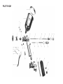
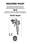
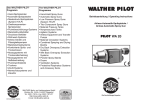
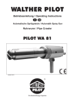
1
Das WALTHER PILOTProgramm
The WALTHER PILOT
Programme
• Hand-Spritzpistolen
• Automatik-Spritzpistolen
• Niederdruck-Spritzpistolen
(System HVLP)
• Pulverbeschichtungs-Systeme
• Materialdruckbehälter
• Drucklose Behälter
• Rührwerk-Systeme
• Airless-Geräte und
Flüssigkeitspumpen
• Materialumlaufsysteme
• Kombinierte Spritz- und
Trockenboxen
• Absaugsysteme mit
Trockenabscheidung
• Absaugsysteme mit
Naßabscheidung
• Pulversprühstände
• Trockner
• Zuluft-Systeme
• Atemschutzsysteme und
Zubehör
• Hand-Held Spray Guns
• Automatic Spray Guns
• Low Pressure Spray Guns
(System HVLP)
• Powder Coating Systems
• Material Pressure Tanks
• Nonpressurized Tanks
• Agitator Systems
• Airless Equipment and
Transfer Pumps
• Material Circulation Systems
• Combined Spraying and
Drying Booths
• Spray Booth with Filter Mats
• Spray Booth with Water-Wash
Function
• Powder Spray Stands
• Dryers
• Ventilation Systems
• Protective Respiratory Systems
and Accessory Items
WALTHER Spritz- und Lackiersysteme GmbH
Kärntner Str. 18-30 • D-42327 Wuppertal
Tel.: 0202 / 787-0 • Fax: 0202 / 787-217
http://www.walther-pilot.de
E-mail: [email protected]
WA LTH ER PI LOT
Betriebsanleitung / Operating Instructions
Spritzpistolen / Spray Guns
PILOT IV / PILOT IV GM
PILOT IV GM
EG-Konformitätserklärung
Declaration of CE-Conformity
Wir, der Gerätehersteller, erklären in alleiniger Verantwortung, daß das Produkt in der
untenstehenden Beschreibung den einschlägigen grundlegenden Sicherheits- und
Gesundheitsanforderungen entspricht. Bei einer nicht mit uns abgestimmten Änderung an dem Gerät oder bei einer unsachgemäßen Verwendung verliert diese
Erklärung ihre Gültigkeit.
We,the manufacturers of the equipment, hereby declare under our sole responsibility
that the product(s) described below conform to the essential safety requirements.
This declaration will be rendered invalid if any changes are made to the equipment
without prior consultation with us.
Hersteller
Manufacturer
Typenbezeichnung
WALTHER Spritz-und Lackiersysteme GmbH
Kärntner Str. 18-30
D-42327 Wuppertal
Tel.: 0202 / 787-0
Fax: 0202 / 787-217
www.walther-pilot.de • Email: [email protected]
Handspritzpistolen PILOT IV / PILOT IV GM
PILOT IV Fließbecher
V 11 401
PILOT IV GM Fließbecher
V 11 441
Intended purpose
Processing of sprayable media
Applied Standards and Directives
EU-Machinery Directive 98 / 37 CE
94 / 9 EC (ATEX Directives)
DIN EN ISO 12100-1
DIN EN ISO 12100-2
EN 1127-1
Verwendungszweck
Verarbeitung spritzbarer Materialien
Angewandte Normen und Richtlinien
EG-Maschinenrichtlinien 98 / 37 EG
94 / 9 EG (ATEX Richtlinien)
DIN EN ISO 12100-1
DIN EN ISO 12100-2
EN 1127-1
Specification according 94 / 9 / CE
Spezifikation im Sinne der Richtlinie 94 / 9 / EG
Kategorie 2
Gerätebezeichnung
Type Designation
WALTHER Spritz-und Lackiersysteme GmbH
Kärntner Str. 18-30
D-42327 Wuppertal
Tel.: 0202 / 787-0
Fax: 0202 / 787-217
www.walther-pilot.de • Email: [email protected]
Hand-held Spray Guns PILOT IV / PILOT IV GM
PILOT IV Gravity-Feed Cup
V 11 401
PILOT IV GM Gravity-Feed Cup
V 11 441
II 2 G c T 6
Tech.File,Ref.:
2403
Category 2
Part marking
II 2 G c T 6
Tech.File,Ref.:
2403
besondere Hinweise :
Das Produkt ist zum Einbau in ein anderes Gerät bestimmt. Die Inbetriebnahme ist so
lange untersagt, bis die Konformität des Endproduktes mit der Richtlinie 98 / 37 / EG festgestellt ist.
special remarks :
The named product is intended for installation in other equipment.Commissioning is prohibited until such time as the end product has been proved to conform to the provision of
the Directives 98 / 37 / CE.
Wuppertal,den 7. Juli 2003
Wuppertal, the 7th of July 2003
i.V.
i.V.
Name: Torsten Bröker
Stellung im Betrieb: Leiter der Konstruktion und Entwicklung
Name: Torsten Bröker
Position: Manager, Design and Development
Diese Erklärung ist keine Zusicherung von Eigenschaften im Sinne der Produkthaftung. Die Sicherheitshinweise der
Produktdokumentation sind zu beachten.
This Declaration does not give assurance of properties in the sense of product liability. The safety instructions provided in the product documentation must be observed at all times.
Ersatzteilliste PILOT IV GM
Inhaltsverzeichnis
Pos.
Nr.
1
2
1
Allgemeines
1.1
1.2
1.3
Kennzeichnung der Modelle
Bestimmungsgemäße Verwendung
Sachwidrige Verwendung
2
Technische Beschreibung
3
Sicherheitshinweise
3.1
3.2
Kennzeichnung der Sicherheitshinweise
Allgemeine Sicherheitshinweise
4
Versorgungsleitungen anschließen
5
Bedienung
5.1
5.2
5.3
5.4
5.5
5.6
Sicherheitshinweise
Inbetrieb- und Außerbetriebsetzen
Spritzbildprobe erzeugen
Spritzbild verändern
Spritzpistole umrüsten
Mängel eines Spritzbildes beheben
6
Reinigung und Wartung
6.1
6.2
6.3
Sicherheitshinweise
Grundreinigung
Routinereinigung
7
Instandsetzung
7.1
7.2
Undichte Nadelpackung austauschen
Materialdüse, und -nadel austauschen
8
9
10
Fehlersuche und -beseitigung
Entsorgung
Technische Daten
3
Ersatzteil-Nr.
Bezeichnung
V 01 101 03
wahlweise
V 01 101 02
V 01 101 02
V 01 101 02
Luftkopfmutter
Luftkopf
2-Loch
4-Loch
6-Loch
000
. . 2*
. . 4*
. . 6*
4
5
6
7
8
9
10
11
wahlweise
V 01 101 10 . . 1*
V 10 441 03 000
V 09 101 74 000
V 00 130 01 040
V 00 130 03 040
V 11 441 01 000
V 10 406 01 . . 3*
V 10 206 02 000
V 10 206 04 000
Materialdüse
(auch in Edelstahl)
Stopfbuchsenschraube
Nadelpackung
Fließbecher
Fließbecherdeckel
Pistolenkörper
Materialnadel
Nadelmutter
Nadelfeder
Stellschraube kompl.
12
13
14
15
16
17
18
19
20
21
22
23
24
25
26
27
28
V 10 206 05 060
bestehend aus:
V 10 206 06 000
V 11 506 07 000
V 10 206 05 000
V 10 204 14 000
V 09 101 14 000
V 10 204 03 000
V 10 904 02 000
V 10 444 01 000
V 00 101 01 000
V 00 101 74 750
V 09 101 15 000
V 10 201 06 000
V 00 103 06 000
V 00 103 04 000
V 00 103 07 000
V 10 101 19 000
V 10 101 18 000
Federbuchse
Kontermutter
Stellschraube
Ventilgehäuse
Dichtung
Ventilfeder
Ventilkegel
Ventilschaft
Doppelnippel
Luftregelventil kompl.
Packung je 6 Scheiben
Ventilbuchse
Abzughebel
Mutter f. Bügelschraube
Bügelschraube
Feder f. Hebelhalterung
Hebelbolzen
Ersatzteile PILOT IV (abweichend von PILOT IV GM)
29
30
31
32
33
V
V
V
V
V
11 401 01 000
00 101 09 000
00 101 10 000
00 101 08 000
00 101 05 000
Pistolenkörper (Messing-vernickelt)
Luftrohr
Pistolengriff
Luftrohrmutter
Reduzierstück
Bei Ersatzteillieferung bitte entsprechende Größe angeben. Wir empfehlen, alle fettgedrukkten Ersatzteile (Verschleißteile) auf Lager zu halten.
1
1.1
Es ist betreiberseitig zu prüfen und sicherzustellen, daß alle technischen Daten
und die Kennzeichnung gemäß ATEX mit den notwendigen Vorgaben übereinstimmen.
Allgemeines
Kennzeichnung der Modelle
Modelle:
Handspritzpistolen PILOT IV / PILOT IV GM
Typ:
PILOT IV Fließbecher
PILOT IV GM Fließbecher
Hersteller:
WALTHER Spritz-und Lackiersysteme GmbH
Kärntner Str. 18-30
D-42327 Wuppertal
Tel.: 0202 / 787-0
Fax: 0202 / 787-217
www.walther-pilot.de • Email: [email protected]
1.2
V 11 401
V 11 441
Bestimmungsgemäße Verwendung
Die Handspritzpistolen PILOT IV und PILOT IV GM dienen ausschließlich der Verarbeitung spritzbarer Medien. Aggressive Materialien sollten nicht verspritzt werden, da
die materialführenden Teile nicht aus Edelstahl-rostfrei gefertigt sind.
Die Modelle PILOT IV und IV GM eignen sich insbesondere zur Verarbeitung von
Farben, Lacken, Grundierungen und Füllern.
Die spritzbaren Materialien dürfen lediglich auf Werkstücke bzw. Gegenstände aufgetragen werden.
Die Temperatur des Spritzmaterials darf 43°C grundsätzlich nicht überschreiten. Die
bestimmungsgemäße Verwendung schließt auch ein, daß alle Hinweise und Angaben
der vorliegenden Betriebsanleitung gelesen, verstanden und beachtet werden.
Das Gerät erfüllt die Explosionsschutz-Forderungen der Richtlinie 94 / 9 EG
(ATEX100a) für die auf dem Typenschild angegebene Explosionsgruppe, Gerätekategorie, und Temperaturklasse.
Beim Betreiben des Gerätes sind die Vorgaben dieser Betriebsanleitung unbedingt
einzuhalten.
Die vorgeschriebenen Inspektions- und Wartungsintervalle sind einzuhalten.
Die Angaben auf den Geräteschildern bzw. die Angaben in dem Kapitel technische
Daten sind unbedingt einzuhalten und dürfen nicht überschritten werden. Eine Überlastung des Gerätes muss ausgeschlossen sein.
Anwendungen, bei denen der Ausfall des Gerätes zu einer Personengefährdung
führen könnten, sind betreiberseitig entsprechende Sicherheitsmaßnahmen vorzusehen.
Falls im Betrieb Auffälligkeiten erkannt werden, muss das Gerät sofort stillgesetzt
werden und es ist mit WALTHER-PILOT Rücksprache zu halten.
Erdung / Potentialausgleich
Es muß sichergestellt werden, dass die Spritzpistole über einen leitfähigen
Luftschlauch ausreichend geerdet ist (maximaler Widerstand 106Ω).
1.3
Sachwidrige Verwendung
Die Spritzpistole darf nicht anders verwendet werden, als es im Abschnitt bestimmungsgemäße Verwendung geschrieben steht. Jede andere Verwendung ist sachwidrig.
Zur sachwidrigen Verwendung gehören z.B.:
• das Verspritzen von Materialien auf Personen und Tiere
• das Verspritzen von flüssigem Stickstoff.
2
Technische Beschreibung
Modelle PILOT IV und IV GM
Bei Betätigung des Abzughebels Pos. 24 wird zuerst das Luftventil Pos. 18 geöffnet (Vorluft) und dann erst die Materialnadel Pos. 9 zurückgezogen. Das Schliessen erfolgt in umgekehrter Reihenfolge.
Die Materialdurchflußmenge ist abhängig vom Durchmesser der Düse. Zusätzlich
läßt sich die Materialmenge durch Ein- bzw. Ausschrauben der Stellschraube Pos.
14 regeln.
Die Regelschraube Pos. 21 dient zur Regulierung der Spritzstrahlbreite. Der Spritzstrahl wird durch Linksdrehen (Ausschrauben) zum Breitstrahl, durch Rechts drehen (Einschrauben) zum Rundstrahl.
Ausführungen:
Die Modelle PILOT IV und PILOT IV GM sind reine Fließbecherpistolen.
Das Gerät darf in explosionsgefährdeten Bereichen nur nach Maßgabe der zuständigen Aufsichtsbehörde eingesetzt werden.
Der zuständigen Aufsichtsbehörde bzw. dem Betreiber obliegt die Festlegung
der Explosionsgefährdung (Zoneneinteilung).
2
3
3
3.1
l
l
Tragen Sie im Arbeitsbereich der Spritzpistole einen Gehörschutz. Der erzeugte
Schallpegel der Spritzpistole beträgt ca. 84 dB (A).
Sicherheitshinweise
Kennzeichnung der Sicherheitshinweise
Achten Sie stets darauf, daß bei Inbetriebnahme, insbesondere nach Montageund Wartungsarbeiten alle Muttern und Schrauben fest angezogen sind.
Warnung
Das Piktogramm und die Dringlichkeitsstufe "Warnung" kennzeichnen eine mögliche
Gefahr für Personen.
Mögliche Folgen: schwere oder leichte Verletzungen.
Verwenden Sie nur Original-Ersatzteile, da WALTHER nur für diese eine sichere
und einwandfreie Funktion garantieren kann.
Achtung
Das Piktogramm und die Dringlichkeitsstufe "Achtung" kennzeichnen eine mögliche
Gefahr für Sachwerte.
Mögliche Folgen: Beschädigung von Sachen.
Bei Nachfragen zur gefahrlosen Benutzung der Spritzpistole sowie der darin verwendeten Materialien, wenden Sie sich bitte an WALTHER Spritz- und Lackiersysteme GmbH, D-42327 Wuppertal.
Hinweis
Das Piktogramm und die Dringlichkeitsstufe "Hinweis" kennzeichnen zusätzliche Informationen für das sichere und effiziente Arbeiten mit der Spritzpistole.
3.2
Benutzen Sie die Spritzpistole nur in gut belüfteten Räumen. Im Arbeitsbereich ist
Feuer, offenes Licht und Rauchen verboten. Beim Verspritzen leichtentzündlicher
Materialien (z. B. Lacke, Reinigungsmittel usw.) besteht erhöhte Gesundheits-, Explosions- und Brandgefahr.
Es muß sichergestellt werden, dass die Spritzpistole über einen leitfähigen Luftschlauch ausreichend geerdet ist (maximaler Widerstand 106Ω).
Schalten Sie vor jeder Wartung und Instandsetzung die Luft- und Materialzufuhr zur
Spritzpistole drucklos - Verletzungsgefahr.
Halten Sie beim Verspritzen von Materialien keine Hände oder andere Körperteile vor
die unter Druck stehende Düse der Spritzpistole - Verletzungsgefahr.
Richten Sie die Spritzpistole nicht auf Personen und Tiere - Verletzungsgefahr.
Beachten Sie die Verarbeitungs- und Sicherheitshinweise der Hersteller von Spritzmaterial und Reinigungsmittel. Insbesondere aggressive und ätzende Materialien können gesundheitliche Schäden verursachen.
Die partikelführende Abluft ist vom Arbeitsbereich und Betriebspersonal fernzuhalten.
Tragen Sie dennoch vorschriftsgemäßen Atemschutz und vorschriftsgemäße Arbeitskleidung, wenn Sie mit der Spritzpistole Materialien verarbeiten. Umherschwebende
Partikel gefährden Ihre Gesundheit.
Versorgungsleitung anschließen
Hinweis
Zur Durchführung der im Folgenden aufgeführten Arbeitsschritte benutzen Sie bitte
die Explosionszeichnung am Anfang dieser Betriebsanleitung.
Allgemeine Sicherheitshinweise
Die einschlägigen Unfallverhütungsvorschriften sowie die sonstigen anerkannten
sicherheitstechnischen und arbeitsmedizinischen Regeln sind einzuhalten.
4
4
l
l
Warnung
Der an der Pistole anstehende Luftdruck darf 8 bar nicht überschreiten, da sonst
kein funktionssicherer Betrieb der Spritzpistole gewährleistet ist.
Warnung
Luftschläuche, die mit einer Schlauchtülle befestigt werden, müssen zusätzlich mit
einer Schlauchschelle gesichert sein.
1. Befestigen Sie den Druckluftschlauch an der Luftleitung (gereinigte Druckluft)
bzw. einem Luftreiniger und an dem Luftanschluß der Spritzpistole Pos. 20.
2. Befüllen Sie den Fließbecher mit gesiebtem Material.
3. Verschließen sie den Fließbecher.
4. Schalten Sie die Druckluftversorgung ein. Die Pistole ist nun betriebsbereit.
5
5.1
Bedienung
Sicherheitshinweise
Beachten Sie bei der Bedienung der Spritzpistole insbesondere die nachfolgenden
Sicherheitshinweise!
• Tragen Sie vorschriftsgemäßen Atemschutz und Arbeitskleidung, wenn Sie mit
der Spritzpistole Materialien verspritzen. Umherschwebende Partikel gefährden
Ihre Gesundheit.
• Tragen Sie im Arbeitsbereich der Spritzpistole einen Gehörschutz. Der erzeugte
Schallpegel der Spritzpistole beträgt ca. 84 dB (A).
• Im Arbeitsbereich ist Feuer, offenes Licht und Rauchen verboten. Beim Verspritzen leicht entzündlicher Materialien (z. B. Lacke) besteht erhöhte Explosions- und Brandgefahr.
5
5.2
Materialdurchflußmenge einstellen
Die Materialmenge läßt sich durch Ein- bzw. Ausschrauben der Stellschraube Pos.
14 regeln. Die Materialmenge wird durch Linksdrehen (Ausschrauben) erhöht,
durch Rechtsdrehen (Einschrauben) verringert.
Inbetrieb- und Außerbetriebsetzen
Bevor Sie die Spritzpistole in Betrieb setzen können, müssen folgende Voraussetzungen erfüllt sein:
• Der Zerstäuberluftdruck muß an der Spritzpistole anstehen.
l
l
Zerstäuberluftdruck regulieren
Der Zerstäuberluftdruck wird am Druckluft-Reduzierventil der Kompressoranlage
eingestellt. Beachten Sie die Anweisungen und Sicherheitshinweise des Herstellers.
Achtung
Der Luftdruck darf 8 bar nicht überschreiten, da sonst kein funktionssicherer Betrieb
der Spritzpistole gewährleistet ist.
Wenn Sie das Spritzbild über die bereits erwähnten Möglichkeiten hinaus verändern wollen, muß die Spritzpistole umgerüstet wer-den (siehe 5.5 Spritzpistole umrüsten).
Warnung
Die Spritzpistole muß nach Arbeitsende immer drucklos geschaltet werden. Die unter
Druck stehenden Leitungen können platzen und nahestehende Personen durch das
ausströmende Material verletzen.
5.3
WALTHER bietet dazu eine Vielzahl unterschiedlicher Luftkopf-/ Materialdüse-/
Nadel-Kombinationen an.
Spritzbildprobe erzeugen
5.5
Eine Spritzbildprobe sollte immer dann erzeugt werden, wenn:
• die Spritzpistole zum erstenmal in Betrieb gesetzt wird
• das Spritzmaterial ausgetauscht wird
• die Pistole zur Wartung oder Instandsetzung zerlegt wurde.
Das Spritzbild kann auf ein Probewerkstück, Blech, Pappe oder Papier abgegeben
werden.
l
l
Warnung
Halten Sie beim Verspritzen von Materialien keine Hände oder andere Körperteile vor
die unter Druck stehende Düse der Spritz-pistole - Verletzungsgefahr.
Die zum Spritzmaterial passende Luftkopf- / Materialdüse- / Nadel-Kombination bildet eine aufeinander abgestimmte Einheit - die Düseneinlage. Tauschen Sie
immer die komplette Düseneinlage aus, damit die gewünschte Spritzbildqualität
erhalten bleibt.
l
Warnung
Unterbrechen Sie vor jeder Umrüstung die Luftzufuhr zur Spritzpistole - Verletzungsgefahr.
Warnung
Achten Sie beim Inbetriebsetzen der Spritzpistole darauf, daß sich keine Person im
Spritzbereich befindet - Verletzungsgefahr.
Hinweis
Zur Durchführung der im Folgenden aufgeführten Arbeitsschritte benutzen Sie bitte
die Explosionszeichnung am Anfang dieser Betriebsanleitung.
1. Setzen Sie die Spritzpistole in Betrieb, um eine Spritzbildprobe zu erzeugen (siehe
5.2 Inbetrieb- und Außerbetriebsetzen).
2. Kontrollieren Siedie Spritzbildprobe und verändern Sie ggf. die Einstellungen an
der Spritzpistole (siehe 5.4 Spritzbild verändern).
Materialdüse und Luftkopf wechseln
1. Schrauben Sie die Luftkopfmutter Pos. 1 ab.
2. Nehmen Sie den Luftkopf Pos. 2 ab.
3. Schrauben Sie die Materialdüse Pos. 3 mit Schlüssel SW 12 aus dem Pistolenkörper aus.
Die Montage erfolgt in umgekehrter Reihenfolge.
5.4
Spritzbild verändern
Sie können an der PILOT IV und PILOT IV GM durch diefolgenden Einstellungen das
Spritzbild verändern.
Breit- bzw. Rundstrahl einstellen
Die Regelschraube Pos. 21 dient zur Regulierung der Spritzstrahlbreite. Der Spritzstrahl wird durch Linksdrehen (Ausschrauben) zum Breitstrahl, durch Rechtsdrehen
(Einschrauben) zum Rundstrahl.
6
Spritzpistole umrüsten
Materialnadel wechseln
1. Schrauben Sie die Stellschraube Pos. 12 - 14 ab.
2. Entnehmen Sie die Nadelfeder Pos. 11.
3. Ziehen Sie die Materialnadel Pos. 9 aus dem Pistolenkörper.
Die Montage erfolgt in umgekehrter Reihenfolge. Das Einstellmaß der Materialnadel beträgt 64 mm von der Nadelspitze bis zur Nadelmutter Pos. 10 gerechnet.
7
5.6
6.2
Mängel eines Spritzbildes beheben
Damit die Lebensdauer und die Funktion der Spritzpistole lange erhalten bleibt,
muß die Spritzpistole regelmäßig gereinigt und geschmiert werden.
Die folgende Tabelle zeigt Ihnen, mit welchen Einstellungen Sie das Spritzbild beeinflussen können.
angestrebtes Spritzergebnis
Spritzbildprobe
6
6.1
Abweichung
erforderliche Einstellung
Spritzbild ist in der Mitte
zu dick
• breitere Spritzstrahlform
einstellen
Spritzbild ist an den
Enden zu dick
• rundere Spritzstrahlform
einstellen
Spritzbild ist ziemlich
grobtropfig
• Zerstäuberluftdruck
erhöhen
Materialauftrag ist in der
Spritzbildmitte sehr dünn
• Zerstäuberluftdruck
verringern
Spritzbild ist in der Mitte
gespalten
• Düsendurchmesser erhöhen
• Zerstäuberluftdruck verringern
Spritzbild ist sehr ballig
• Zerstäuberluftdruck erhöhen
Reinigung und Wartung
Sicherheitshinweise
• Unterbrechen Sie vor jeder Wartung die Luftzufuhr zur Spritzpistole -Verletzungsgefahr.
• Im Arbeitsbereich ist Feuer, offenes Licht und Rauchen verboten. Beim Verspritzen
leichtentzündlicher Materialien (z. B. Reinigungsmittel) besteht erhöhte Explosionsund Brandgefahr.
• Beachten Sie die Sicherheitshinweise des Reinigungsmittel-Herstellers. Insbesondere aggressive und ätzende Reinigungsmittel können gesundheitliche Schäden
verursachen.
8
Grundreinigung
l
l
Achtung
Legen Sie die Spritzpistole nie in Lösemittel oder ein anderes Reinigungsmittel.
Die einwandfreie Funktion der Spritzpistole kann sonst nicht garantiert werden.
Achtung
Verwenden Sie zur Reinigung keine harten oder spitzen Gegenstände. Präzisionsteile der Spritzpistole könnten sonst beschädigt werden und das Spritzergebnis
verschlechtern.
Verwenden Sie zur Reinigung der Spritzpistole nur Reinigungsmittel, die vom
Hersteller des Spritzmaterials angegeben werden und die folgenden Bestandteile
nicht enthalten:
• halogenierte Kohlenwasserstoffe
(z. B. 1,1,1, Trichlorethan, Methylen-Chlorid usw.)
• Säuren und säurehaltige Reinigungsmittel
• regenerierte Lösemittel (sog. Reinigungsverdünnungen)
• Entlackungsmittel.
Die o.g. Bestandteile verursachen an galvanisierten Bauteilen chemische Reaktionen und führen zu Korrosionsschäden.
Für Schäden, die aus einer derartigen Behandlung herrühren, übernimmt
WALTHER PILOT keine Gewährleistung.
Reinigen Sie die Spritzpistole
• vor jedem Farb- bzw. Materialwechsel
• mindestens einmal wöchentlich
• materialabhängig und je nach Verschmutzungsgrad mehrfach wöchentlich.
Sie erhalten so die sichere Funktion der Spritzpistole.
1. Zerlegen Sie die Pistole gemäß 5.5 Spritzpistole umrüsten.
2. Reinigen Sie den Luftkopf und die Materialdüse mit einem Pinsel und dem Reinigungsmittel.
3. Reinigen Sie alle übrigen Bauteile und den Pistolenkörper mit einem Tuch und
dem Reinigungsmittel.
4. Bestreichen Sie folgende Teile mit einem dünnen Fettfilm:
• Materialnadel
• Nadelfeder
• alle gleitenden Teile und Lagerstellen
• Die beweglichen Innenteile sind wenigstens einmal wöchentlich zu fetten
• Die Federn sollten ständig mit einem leichten Fettüberzug versehen sein.
Verwenden Sie dazu ein säurefreies, nicht harzendes Fett und einen Pinsel.
Anschließend wird die Spritzpistole in umgekehrter Reihenfolge zusammengesetzt.
9
6.3
Reparaturset:
WALTHER PILOT hält für die Handspritzpistolen PILOT IV und PILOT IV GM
einen Reparaturset bereit, der sämtliche Verschleißteile enthält:
Routinereinigung
Bei Farbwechseln oder nach Arbeitsende können Sie die Spritzpistole auch reinigen,
ohne diese dabei zerlegen zu müssen.
Art. Nr.: V 16 004 02 . . 1
Um die Routinereinigung durchführen zu können, müssen Sie die folgenden
Arbeitsschritte durchführen:
1. Befüllen Sie den gesäuberten Fließbecher mit einem zum verspritzten Material
passenden Reinigungsmittel.
2. SetzenSiedieSpritzpistoleinBetrieb (siehe 5.2 Inbetriebsetzen).
3. Setzen Sie die Spritzpistole erst außer Betrieb, wenn diese nur noch klares Reinigungsmittel verspritzt.
Die gesamte Spritzanlage sollte nun bis zum nächsten Einsatz drucklos geschaltet
werden.
7
l
Instandsetzung
Bestehend aus: Luftkopf (Pos. 2), Materialdüse (Pos. 3), Nadelpackung (Pos. 5),
Materialnadel (Pos. 9), Nadelmutter (Pos. 10), Nadelfeder (Pos. 11), Ventilfeder
(Pos. 17), Ventilkegel (Pos. 18), Packung je sieben Scheiben (Pos. 22).
8
l
Fehlersuche und -beseitigung
Warnung
Schalten Sie vor jeder Instandsetzung die Zerstäuberluft zur Spritzpistole drucklos
- Verletzungsgefahr.
Fehler
Warnung
Unterbrechen Sie vor jeder Umrüstung die Luft- und Materialzufuhr zur Spritzpistole
- Verletzungsgefahr.
Hinweis
Zur Durchführung der im Folgenden aufgeführten Arbeitsschritte benutzen Sie bitte
die Explosionszeichnung (Faltblatt) am Anfang dieser Betriebsanleitung.
7.1
Pistole tropft
1. Entfernen Sie die Materialnadel gemäß 5.5 Spritzpistole umrüsten.
2. Schrauben Sie die Stopfbuchse Pos. 4 aus dem Pistolenkörper aus.
3. Entfernen Sie die Nadelpackung Pos. 5.
Die Montage erfolgt in umgekehrter Reihenfolge
7.2
Materialdüse und -nadel austauschen
Zerlegen Sie die Spritzpistole gemäß Abschnitt 5.5 Spritzpistole umrüsten.
Hinweis
Alle beweglichen und gleitenden Bauteile müssen vordem Einbau in den Pistolenkörper mit einem säurefreien, nicht harzenden Fett eingefettet werden.
10
Abhilfe
reinigen, gemäß 5.5 Spritzpistole
umrüsten
Materialnadel oder -düse
beschädigt
erneuern, gemäß 5.5
Spritzpistole umrüsten
Stopfbuchse Pos. 4 zu fest etwas lockern
angezogen
Undichte Nadelpackung austauschen
Hinweis
Die aus dem Pistolenvorsatz entnommene Nadelpackung darf nicht wieder verwendet werden, da sonst eine funktionssichere Dichtwirkung nicht gewährleistet ist.
Ursache
Materialnadel oder -düse
verschmutzt
Stoßweiser oder
flatternder
Spritzstrahl
Nadelfeder Pos. 11 nicht in Materialnadel ausbauen und
Ordnung, evtl. gebrochen
Feder austauschen gemäß 5.5
Spritzpistole umrüsten
Materialnadel stimmt nicht
mit Düsengröße überein
auf gleiche Durchmesser achten
Stellschraube Pos. 14 zu
weit nach hinten gedreht
zu wenig Material im
Fließbecher
Stellschraube etwas
einschrauben (Rechtsdrehen)
Material auffüllen
Fließbecher wird während gerader halten
des Spritzvorgangs zu stark
geneigt
die Materialdüse ist lose
oder beschädigt
Materialleckage an Stopfbuchse zu lose
der Stopfbuchsenschraube Pos. 4
Nadelpackung Pos. 5 verschlissen
Ventilkegel Pos. 18 undicht
Pistole bläst in
oder
Ruhestellung
Ventilschaft Pos. 19
schwergängig
Spritzstrahl einsei- Lufkopf verschmutzt
tig
festziehen
festziehen
austauschen
austauschen
etwas lösen
Luftkopf säubern
11
9
Entsorgung
Die bei der Reinigung und Wartung anfallenden Materialien sind den Gesetzen und
Vorschriften entsprechend sach- und fachgerecht zu entsorgen.
l
Warnung
Beachten Sie insbesondere die Hinweise des Herstellers der Spritz- und Reinigungsmittel. Unachtsam entsorgtes Material gefährdet die Gesundheit von Mensch und
Tier.
10
Technische Daten
Netto-Gewicht PILOT IV:
Netto-Gewicht PILOT IV GM:
Düsenausstattung
nach Wahl:
630 g
460 g
0,5 • 0,8 • 1,0 • 1,2 • 1,5 • 1,8
• 2,0 • 2,5 • 3,0 • 3,5 mm ø
Luftköpfe*:
Zweiloch-, Vierloch-, Sechslochkopf
*weitere Luftköpfe auf Anfrage.
max. Zerstäuberdruck:
8 bar
max. Betriebstemperatur
der Spritzpistole:
43 °C
Schallpegel
(gemessen in ca. 1 m
Abstand zur Spritzpistole)
84 dB (A)
Luftverbrauch:
Zerstäuberluftdruck
Rundstrahl
Breitstrahl
1,0
2,0
3,0
4,0
5,0
6,0
110 l / min.
140 l / min.
170 l / min.
190 l / min.
200 l / min.
220 l / min.
180
240
280
320
350
390
bar
bar
bar
bar
bar
bar
Technische Änderungen vorbehalten.
12
l
l
l
l
l
l
/
/
/
/
/
/
min.
min.
min.
min.
min.
min.
Listing of Replacement Parts PILOT IV GM
Listing of Contents
Item
No.
1
2
1
General
1.1
1.2
1.3
Identification of Model Versions
Normal Use
Improper Use
2
Technical Description
3
Safety Instructions
3.1
3.2
Safety Warning Symbols
General Safety Instructions
4
Connection of Input Line
3
Part No.
V 01 101
optional
V 01 101
V 01 101
V 01 101
Description
03 000
02 . . 2*
02 . . 4*
02 . . 6*
Retaining Nut f. Air Cap
Air Cap
2-Bore
4-Bore
6-Bore
4
5
6
7
8
9
10
11
optional
V 01 101 10 . . 1*
V 10 441 03 000
V 09 101 74 000
V 00 130 01 040
V 00 130 03 040
V 11 441 01 000
V 10 406 01 . . 3*
V 10 206 02 000
V 10 206 04 000
Material Nozzle
(also available in stainness steel)
Packing Gland Screw
Needle Seal Packing
Gravity-Feed Cup
Cover for Feed Cup
Gun Body
Material Needle
Needle Retaining Nut
Needle Spring
Set Adjusting Screw compl.
12
13
14
15
16
17
18
19
20
21
22
23
24
25
26
27
28
V 10 206 05 060
consisting of:
V 10 206 06 000
V 11 506 07 000
V 10 206 05 000
V 10 204 14 000
V 09 101 14 000
V 10 204 03 000
V 10 904 02 000
V 10 444 01 000
V 00 101 01 000
V 00 101 74 750
V 09 101 15 000
V 10 201 06 000
V 00 103 06 000
V 00 103 04 000
V 00 103 07 000
V 10 101 19 000
V 10 101 18 000
Spring Retaining Bush
Lock Nut
Adjusting Screw
Valve Housing
Seal
Valve Spring
Valve Cone
Valve Shank
Double Nipple
Air Regulating Valve compl.
Packing (6 Disks)
Valve Bushing
Trigger
Nut for U-Bolt
U-Bolt
Spring for Trigger-Mount
Trigger Screw
Replacement Parts PILOT IV (deviating from PILOT IV GM)
29
30
31
32
33
V
V
V
V
V
11 401 01 000
00 101 09 000
00 101 10 000
00 101 08 000
00 101 05 000
Gun Body (Nickled Brass)
Air Tube
Gun Handle
Retaining Nut for Air Tube
Reducer
When ordering replacement parts please quote the respective size/s. lt is recommended to
keep in stock all bold-printed parts (wearing parts) to avoid work stoppages.
5
Operational Handling
5.1
5.2
5.3
5.4
5.5
5.6
Safety Instructions
Starting / Stopping Requirements
Spray Pattern Test
Spray Pattern Adjustments
Retooling the Spray Gun
Correction of Spray Pattern Imperfections
6
Cleaning and Maintenance
6.1
6.2
6.3
Safety Instructions
Cleaning Complete
Cleaning Routine
7
Repairs / Replacements
7.1
7.2
Replacement of defective Needle Seal Packing
Replacement of Material Control Nozzle and Needle
8
9
10
Trouble shooting and Corrective Action
Disposal of Cleaning / Servicing Substances
Specification Data
1
1.1
The operator must check and ensure that all technical data and the marking of the
equipment in accordance with ATEX are compliant with the necessary requirements.
General
Identification of Model Versions
Models:
Hand-held Spray Guns PILOT IV / PILOT IV GM
Type:
PILOT IV Gravity-Feed Cup
PILOT IV GM Gravity-Feed Cup
Manufacturer:
WALTHER Spritz-und Lackiersysteme GmbH
Kärntner Str. 18-30
D-42327 Wuppertal
Tel.: 00 49 (0)202 / 787-0
Fax: 00 49 (0)202 / 787-217
www.walther-pilot.de • Email: [email protected]
1.2
V 11 401
V 11 441
Normal Use
The hand-held spray guns PILOT IV and PILOT IV GM are exclusively designed for
use with sprayable media. Spraying aggressive media should be avoided as the wetted parts are not made of stainless specialty steel.
The guns are especially suited for processing / handling paints and lacquers, primers
and fillers.
The operator must provide corresponding safety measures for all applications in
which the breakdown of the equipment might lead to danger to persons.
If any irregularities are observed while the equipment is in operation, the equipment must be put out of operation immediately and WALTHER PILOT must be
consulted.
Grounding / Equipotential Bonding
Measures must be taken to ensure that the spray gun is sufficiently grounded (earthed) by means of a conductive air hose (maximum resistance 106 Ω).
1.3
This spray gun shall not be used for purposes other than set forth in the above
Chapter Normal Use. Any other form of use and/or application is prohibited.
The improper use also includes such operations as may be:
• spraying of material onto persons and animals
• spraying of liquid nitrogen.
2
Please note that sprayable materials may only be applied to work pieces and/or similar items.
The temperature of the spraying materials shall never exceed 43° C. The term normal
use also implies that any and all safety warnings, operational handling details, etc., as
stated in these operating instructions, are carefully read, understood and duly complied with.
This equipment complies with the explosion protection requirements of Directive 94 /
9 / EC (ATEX 100a) for the explosion group, equipment category and temperature
class indicated on the type plate. When using the equipment, the requirements specified in these Operating Instructions must be observed at all times.
The technical data indicated on the equipment rating plates and the specifications in
the chapter "Technical Data" must be complied with at all times and must not be
exceeded. An overloading of the equipment must be ruled out.
Improper Use
Technical Description
Models PILOT IV and IV GM
When actuating the trigger (Item 24) the air valve (Item 18) is opened (preliminary
air); slightly hereafter the material needle (Item 9) is retracted. Closing is in reverse
order.
The material flow rate depends an the diameter of the nozzle.
In addition, the material flow rate can be adjusted by screwing in or out the adjusting screw (Item 14).
Through the regulating screw (Item 21) the spraying pattern can be controlled, i. e.
left-hand turn = wide jet, right-hand turn = round jet.
Design versions:
Model versions PILOT IV/ IV GM are to be used with gravity-feed cup only.
The equipment may be used in potentially explosive atmospheres only with the authorisation of the relevant supervisory authority.
The relevant supervisory authority or the operator of the equipment are responsible for determining the explosion hazard (zone classification).
2
3
3
3.1
l
l
Always wear hearing protection when using the gun or when in the vicinity of a gun
that is in use. The noise level generated by the spray gun is approx. 84 dB (A).
Safety Instructions
Safety Warning Symbols
After carrying out assembly or maintenance work, always ensure that all nuts, bolts
and screw connections have been fully tightened before the gun is used.
Warning
This pictograph and the accompanying warning note "Warning" indicate possible risks
and dangers for yourself.
Possible consequences: Injuries of any kind.
Use only original replacement parts, since WALTHER can only guarantee safe and
faultfree operation for original parts.
Caution
This pictograph and the accompanying warning note "Caution" indicate possible
damage to equipment.
Possible consequences: Damage to equipment, workpieces, etc.
For further information on the safe use of the spray gun and the spraying materials, please contact WALTHER Spritz- und Lackiersysteme GmbH, D-42327
Wuppertal, Germany
4
Note
This pictograph and the accompanying note "Notice" indicate additional and useful
Information to help you handling the spray gun with even greater confidence and efficiency.
3.2
General Safety Instructions
All applicable accident prevention rules and regulations as well as other recognised
industrial safety and health rules and regulations must be observed at all times.
Use the spray gun only in well-ventilated rooms. Fire, naked flames and smoking are
strictly prohibited within the working area. WARNING – during the spraying of flammable materials (e.g. lacquers, cleaning agents, etc.), there is an increased risk to health
as well as an increased risk of explosion and fire.
Measures must be taken to ensure that the spray gun is sufficiently grounded (earthed) by means of a conductive air hose (maximum resistance 106 Ω).
Before carrying out maintenance or servicing work, always ensure that the air and
material feed to the spray gun have been de-pressurised. Risk of injury!
When spraying materials, do not place your hands or other parts of the body in front
of the pressurised nozzle or the spray gun. Risk of injury!
Never point the spray gun at persons or animals. Risk of injury!
Always observe the spraying and safety instructions given by the manufacturers of
the spraying material and the cleaning agent. Aggressive and corrosive materials in
particular can be harmful to health.
Exhaust air containing particles (overspray) must be kept away from the working area
and personnel. In spite of these measures, always wear the regulation breathing
masks and protective overalls when using the gun. Airborne particles represent a
serious health hazard!
4
Connection of Input Lines
Note
Use the exploded view at the beginning of these operating instructions to perform
the operational steps described hereafter.
l
l
Warning
The air pressure at the gun shall not exceed 8 bar; otherwise a safe operation of
the spray gun cannot be ensured.
Warning
The air hose which is installed with a hose grommet must be additonally secured
with a hose clamp.
1. Connect the air hose to the air outlet valve (cleaned compressed air) - or an air
cleaner - and to the air inlet of the spray gun (Item 20).
2. Fill the gravity-feed cup with screened material.
3. Close the gravity-feed cup.
4. Switch an the pneumatic system. The spray gun can then be taken into operation.
5
5.1
Operational Handling
Safety Instructions
Pay special attention to the following safety warnings when using the spray gun!
• Make sure to wear proper respiratory protection masks and protective overalls,
whenever you are operating this spray gun. Airborne particles represent a health
hazard.
• Make sure to wear suitable hearing protectors. The spray guns produce sound
levels of approx. 84 dB (A).
• Make sure your working area is absolutely free from open fires and naked lights and anybody smoking. Spraying of readily flammable media (e.g. lacquers) is
always accompanied by the risk of fire and explosion.
5
5.2
Adjusting the Material Flow Rate
The material flow rate can be adjusted by screwing in / screwing out the set screw
(Item 14). The material rate is increased by turning it to the left (screwing out) and
decreased by turning it to the right (screwing in).
Starting / Stopping Requirements
The following requirements must be met beforethis spray gun can be taken into operation:
• The atomizing air pressure must be available at the gun.
l
l
Adjustment of the Atomizing Air Pressure
The atomizing air pressure is to be adjusted at the pressure reducing valve of the
compressor system. Please comply with the operating instructions and safety warnings issued by the manufacturer.
Caution
The air pressure shal I not exceed 8 bar, as otherwise the functional reliability of the
spray gun will suffer.
If you wish to change the spraying pattern beyond the adjustments outlined so far,
the spray gun must be retooled (see 5.5 Retooling the spray gun).
Warning
It is important to remember that the spray gun must be relieved of all pressures when
work is terminated - lines left in pressurized condition could burst with their contents
likely to injure anybody standing nearby.
5.3
WALTHER offers a great variety of air cap / material nozzle / needle combinations
for this purpose.
Spray Pattern Test
5.5
Spray pattern tests should be performed whenever:
• the spray gun is taken into operation for the first time
• the spraying medium is changed
• the spray gun was taken apart for servicing or repairs.
The spray pattern is best tested using a workpiece sample, a sheet of metal, cardboard or paper.
l
l
Warning
When spraying materials, do not place your hands or other parts of the body in front
of the pressurised nozzle or the spray gun. Risk of injury!
Warning
Make sure that nobody is present in the spraying zone when the gun is started - imminent risk of injury.
1. Start the gun to produce a spray pattern sample (see 5.2 Starting / Stopping Requirements).
2. Inspect the sample and adjust the settings of the gun, if necessary (see 5.4 Spray
Pattern Adjustments).
5.4
Spray Pattern Adjustments
The spray pattern of the PILOT IV and PILOT IV GM can be adjusted as follows.
Wide and / or Round Jet Pattern
The regulating screw (Item 21) controls the width of the jet. By turning it to the left a
wide-jet pattern will emerge; by screwing it to the right a round-jet pattern can be
achieved.
6
Retooling the Spray Gun
Combinations of air cap, material nozzle and needle, designed to match specific
spraying media type and grades, form a unit - namely the nozzle insert assembly,
which must always be interchanged as a complete assembly to maintain the desired spray-finish quality standard.
l
Warning
Prior to retooling: Make sure that the spray gun is in unpressurized condition, i.e.
the air input must be shut off - if not, imminent risk of injury.
Note
Please use the exploded view at the beginning of these operating instructions in
order to perform the following procedures.
Replacement of Material Nozzle and Air Cap
1. Unscrew the retaining nut of the air cap (Item 1).
2. Remove the air cap (Item 2).
3. Unscrew the material nozzle (Item 3) from the gun body using a size 12 wrench.
Installation is performed in reverse order.
Replacement of Material Needle
1. Unscrew the adjusting screw (Item 12- 14).
2. Remove the spring (Item 11).
3. Pull out the material needle (Item 9) from the gun body.
Installation is performed in reverse order. The setting dimension for the needlecontrolled initial air input is 64 mm, measured from the point of the material control
needle to the needle retaining nut (Item 10).
7
5.6
6.2
Correction of Spray Pattern Imperfections
The spray gun should be frequently cleaned and lubricated to ensure a long service life and functional reliability.
The table below shows what to do to correct a spray pattern.
desireable spray-painting result
Spray Pattern
Fault
6
6.1
Adjustment
Swollen centre
• Spray jet should be flatter
Swollen ends
• Spray jet should be rounder
Coarse pearl effect
• Increase atomising air pressure
Unduly thin paint
layer in centre
• Decrease atomising air pressure
Split centre
• Increase nozzle diameter
• Reduce atomising air pressure
• Increase material pressure
Crowned centre
• Decrease material pressure
• Increase atomising air pressure
Cleaning and Maintenance
Safety Instructions
• Make sure that the spray gun is in unpressurized condition, i.e. the air input must
be shut off - if not, imminent risk of injury.
• Open fires, naked lights and smoking is prohibited in the working area. There is an
increasing risk of fire and explosion, when spraying readily flammable media (such
as cleaning solutions).
• Observe all processing specifications and safety warnings issued by the manufacturer of cleaning media. Especially aggressive and acidiferous media represent risks
and hazards to personal health.
8
Cleaning Complete
l
l
Caution
Never immerse the spray gun in solvent or any other cleaning solution as such
measure is very likely to affect the functional reliability and efficiency of the gun.
Caution
Do not use any hard, pointed or sharp-edged objects when cleaning the spray
gun, as the precision-made parts can easily be damaged and are likely to affect
your spraying results.
Clean the gun only with cleaning solutions recommended by the manufacturer of
the spraying material which do not contain any of the following constituents:
• halogenated hydrocarbons
(e.g. 1,1,1-trichloroethane, methylene chloride, etc.)
• acids and acidiferous cleaning solutions
• regenerated solvents (so-called cleaning dilutions)
• paint removers.
The above constituents cause chemical reactions with electroplated components
resulting in corrosion damage.
WALTHER PILOT is not responsible for damages resulting from this kind of treatment.
Clean the spray gun
• prior to each change of the spraying medium
• at least once a week
• as often as may be required by the spraying medium handled and the resultant
degree of fouling.
Performing these steps will ensure safe gun operation.
1. Dismantle the spray gun accordaning to 5.5 Retooling of Spray Gun.
2. Use a soft brush together with a compatible cleaning solution to clean the air
cap and nozzle.
3. Use a suitable cloth with a compatible cleaning solution to clean the gun body
and all remaining parts.
4. Apply a thin layer of grease to the following parts:
• material control needle
• needle spring
• all sliding parts and bearing points
• The moveable interior parts have to be greased at least once a week.
• The springs have always to be coated with a thin layer of grease.
Make sure to use a non-acidic, non-resinogenic grease and apply this with a soft
brush. Afterwards, assemble the spray gun in reverse order.
9
6.3
Cleaning Routine
Repair Kit:
A WALTER PILOT repair kit is available for the hand-held spray guns PILOT IV
and PILOT IV GM which comprises all wearing parts:
The spray gun does not have to be necessarily dismantled for cleaning if and when
the paint is changed in regular intervals or upon termination of work (depending, of
course, an the material used).
Repair Kit Art. No.: V 16 004 02 . . 1
Consisting of: air cap (Item 2), material nozzle (Item 3), needle seal packing (Item
5), material control needle (Item 9), needle retaining nut (Item 10), needle spring
(Item 12), valve spring (Item 17), valve cone (Item 18) and packing (Item 22).
The following requirements must be met before the routine cleaning work can be performed:
1. The cleaned gravity-feed cup has to be filled with a cleaning solution compatible
with the sprayed material.
2. Take the spray gun into operation (see 5.2 Starting / Stopping Requirements).
3. Do not stop the spray gun until clear cleaning solution emerges from the nozzle.
All pressures should be removed from the complete spraying system until it is taken
into operation again.
7
l
Repairs / Replacements
l
Troubleshooting and Corrective Action
Warning
Prior to any servicing and repair work: Make sure that the spray gun is in unpressurized condition, i.e. the air input must be shut off - if not, imminent risk of injury.
Fault
7.1
Replacement of defective Needle Seal Packing
1. Remove the material control needle (see 5.5 Retooling of Spray Gun).
2. Remove the needle packing gland (Item 4) from the gun body.
3. Remove the needle seal packing (Item 5).
Assembly is performed in reverse order.
Note
Never reinstall a used needle seal packing, as otherwise the functional sealing reliability of the spray gun will suffer.
7.2
Replacement of Material Control Nozzle and Needle
Disassemble the spray gun according to 5.5 Retooling the Spray Gun.
Note
All sliding and moveable parts must be lubricated with a non-acidic, non-resinogenic
grease prior to installation.
Cause
Corrective Action
Material needle or nozzle fou- Clean - see 5.5 Retooling the
led
Spray Gun
Warning
Prior to any repairs /r eplacements: Make sure that the spray gun is in unpressurized
condition, i.e. all air and material inputs must be shut off - if not, imminent risk of injury.
Note
Please use the exploded view at the beginning of these operating instructions in
order to perform the following procedures.
10
8
Material needle or nozzle
damaged
Gun is dripping
Replace - see 5.5 Retooling the
Spray Gun
Needle packing gland (Item 4) Loosen slightly
too tight
Needle spring (Item 11)
defective, possibly broken
Remove material needle and
nee dle spring - see 5.5 ...
Size mismatch between mate- Use same diameters
rial needle and nozzle
Adjusting screw (Item 14) turned too far to the back
Level in gravity-feed too low
Gravity-feed cup is tilted too
Spray jet pulsa- much during spraying operating or unsteady tion
Material nozzle is loose or
damaged
Packing gland too loose
Materialleckage
from Packing
Gland
Needle seal packing (Item 5)
damaged
Gun keeps blo- Valve cone (Item 18) damaged
wing in off con- or
dition
Valve shank (Item 19) binds
Spray jet one- Horn bores fouled
side
Screw in adjusting screw slightly
(turn clockwise)
Top-up material level
Keep straight
Tighten
Tighten
Replace
Replace
Loosen
Clean air cap
11
9
Disposal of Cleaning / Servicing Substances
Disposal of any such substances must be in accordance with all applicable local and
national regulations, directives and laws.
l
Warning
Particular attention is drawn to all processing specifications and safety warnings issued by the manufacturers of spraying and cleaning media.Remember: The irrproper
disposal of any toxic waste material represents a serious threat to the environment,
i.e. to the health of mankind and animal life.
10
Specification Data
Net Weight PILOT IV:
Net Weight PILOT IV GM:
630 g
460 g
Available range
of spray nozzles:
0.5 • 0.8 • 1.0 • 1.2 • 1.5 • 1.8
• 2.0 • 2.5 • 3.0 • 3.5 mm ø
Air Caps*:
two-bore -, four-bore -, six-bore air cap
*other air caps on demand.
Max. Spraying Pressure:
8 bar
Max. Operating Temperature
of the Spray Gun:
43 °C
Sound Level
(measured at a distance
of 1 m from the spray gun)
84 dB (A)
Air Consumption:
Atomising Air
Pressure
Round Jet
Flat Jet
1.0
2.0
3.0
4.0
5.0
6.0
110 l / min.
140 l / min.
170 l / min.
190 l / min.
200 l / min.
220 l / min.
180
240
280
320
350
390
bar
bar
bar
bar
bar
bar
Right to effect technical changes reserved.
12
l
l
l
l
l
l
/
/
/
/
/
/
min.
min.
min.
min.
min.
min.