1
Instruction manual
Operating instructions
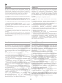
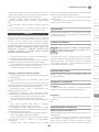
possible to chamfer the edges of the workpiece.
• Place the 90° V-groove (5) on the edge of the workpiece and
move it along it.
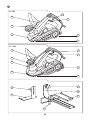
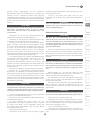
Setting cut depth [F2]
EN
Turn the additional handle with cut-depth set (6) to the right
as far as it stops.
• Put the planer on a flat surface and turn the
additional handle with cut-depth set (6) to the left until
the planer sole plate lies flat on the surface and the «O»
mark on the knob is level with the mark on the housing.
To set the desired cut depth turn the knob to the right for any
cut depth up to a permitted maximum of 3 mm (PL-900), 3.5 mm
(PL-1200). The marks on the setting knob serve as a guide.
Planing
First, place the forward sole plate of the planer flat on the
surface of the workpiece, but so that the cutters do not come
into contact with it.
Start the planer up and wait for the cutters to reach full speed.
Then push the planer carefully forward. When starting planing,
apply pressure to the front end of the planer and, when finishing
planing, to the rear end.
Planing is easier if the workpiece is set at an angle, so that you
work forward and downwards.
The speed and cut depth determine the surface quality. The
planer cuts evenly at a speed which prevents jamming through
chips.
For rough-cutting the cut depth can be increased, while for
optimum surface quality the cut depth should be reduced and
the planer moved more slowly.
Rabbeting
ATTENTION
PL-1200 has the rabbeting depth guide incorporate on the
machine; PL-900 has external rabbeting guide.
(PL-900)
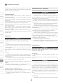
• Place the planer on a firm level so that the blade, rabbeting
depth guide and base plate all line up.
• Set the rabbeting depth guide (12) to the desired depth
according to the scale and lock it using the adjustment screw
(13).
(PL-1200)
• Place the planer on a firm level so that the blade, rabbeting
depth guide and base plate all line up.
• Set the rabbeting depth guide (12) to the desired depth by
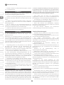
turning the adjustment screw (13). [F3]
The planing width can be adjusted using the parallel guide (8):
• Undo the wing screw (9), set the guide to the desired width
and lock it in place by tightening the screw again.
Bevelling and chamfering edges [F4]
The V-groove (5) on the bottom of the front sole plate makes it
Maintenance and storage
CAUTION
Before any work on the machine itself, pull the mains plug.
• Always keep the tool and the ventilation slots (if present)
cleaned. Regular cleaning and maintenance of the appliance
will ensure efficiency and prolong the life of your tool.
• If the tool should fail despite the rigorous manufacturing
and testing procedures, the repair should be carried out by an
authorized IVT customer service.
• Keep all nuts, bolts, and screws tight, to be sure the tool is in
safe working condition.
• Replace worn or damaged parts for safety.
• Use only original spare parts. Parts not produced by
manufacturer may cause poor fit and possible injury.
• Store the tool in a dry room out of reach of kids and away
from any flammable material.
• Never wet the device or spray water on it!
• It is necessary to sharpen in due time blunted blades or
to replace the damaged blades. Continued use of blunt or
worn blades will reduce the efficiency of the planer and could
overload the motor.
• In order to avoid imbalances and vibrations always replace
or sharpen both knives at the same time.
• It is forbidden to work only with one knife.
• Only use blades which are delivered together with original
tool or available from the IVT authorized shops.
Replacement of the blades
ATTENTION
The new blade must be the same size and weight as the old
one; otherwise the shaft will vibrate, the cutting quality will
be pour and the tool may be damaged.
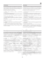
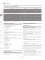
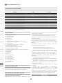
(PL-900) [F5]
• Loosen the three attachment screws (14) with a socket
wrench.
• Remove the set plate (20) holding the blade (17). [F6]
WARNING
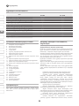
Remember how the blade is fitted before removing it. [F7]
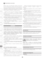
• Place the new blade (17) against the set plate (20) in the
same position as the previous blade. Make sure that the slots
in the blade (17) line up with the guides on the drum plate (18)
and that the two slots on the drum plate are lined up with the
two holes in the set plate (20). When adjusting the amount of
the blade protrusion, make sure that it sticks out at least 1.1 mm
16