1
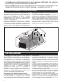
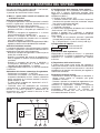
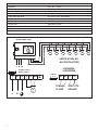
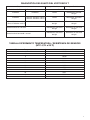
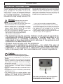
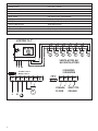
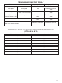
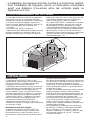
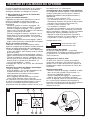
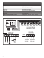
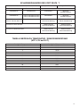
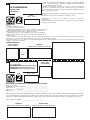
Libretto Istruzioni
Instruction booklet
Notice de pose et d’entretien
Betriebsanleitung
VORT DELTA T
MADE IN ITALY COD. 5.471.084.181
VORTICE ELETTROSOCIALI S.p.A.
Strada Cerca, 2 - frazione di Zoate
20067 TRIBIANO (MI)
Tel. (+39) 02-90.69.91
Fax (+39) 02-90.64.625
ITALIA
21/05/2015
VORTICE FRANCE
15/33 Rue Le Corbusier
Europarc
94046 CRETEIL Cedex
Tel. (+33) 1-55.12.50.00
Fax (+33) 1-55.12.50.01
FRANCE
VORTICE LIMITED
Beeches House - Eastern Avenue
Burton on Trent
DE13 0BB
Tel. (+44) 1283-492949
Fax (+44) 1283-544121
UNITED KINGDOM
Prima di installare e collegare il prodotto,
leggere attentamente queste istruzioni. Vortice
non può essere considerata responsabile per
eventuali danni a persone o cose causate
dalla non applicazione di quanto contenuto
nel libretto.
Seguire tutte le istruzioni per assicurare
la sua durata, la sua affidabilità elettrica
e meccanica.
Conservare sempre questo libretto d’istruzioni.
Before installing and connecting the unit,
carefully read these instructions. Vortice cannot
assume any responsibility for damage
to property or personal harm resulting from
failure to abide by the conditions given
in this booklet.
Following these instructions will assure long
service life and overall electrical and
mechanical reliability.
Keep this instruction booklet in safe place.
Avant d’utiliser le produit et de le connecteur,
lire attentivement ces instructions. Vortice ne
pourra être tenu pour responsable des
dommages éventuels causés aux personnes ou
aux choses par suite du non respect de ce qui
est présénté dans le présent livret.
Le respect de toutes les indications reportées
dans ce livret garantira une longue durée de vie
ainsi que la fiabilité électrique et mécanique de
cet appareil.
Conserver toujours à portée de main le présent
livret d’instructions
Diese Anleitungen vor der Installation und dem
Verbinden des Gerätes aufmerksam durchlesen.
Vortice kann nicht für eventuelle Schäden an
Personen oder Sachgegenstände haftbar
gemacht werden, die durch das Missachten des
Inhalts dieses Handbuchs verursacht werden.
Alle Anweisungen befolgen, damit eine lange
Lebensdauer und eine zuverlässige elektrische
und mechanisch Funktionsfähigkeit
gewährleistet wird.
Dieses Benutzerhandbuch stets gut
aufbewahren.
2
Indice
Descrizione ed impiego . . . . . . . . . . . . . . 3
Attenzione. . . . . . . . . . . . . . . . . . . . . . . . . 3
Avvertenza . . . . . . . . . . . . . . . . . . . . . . . . 3
Funzionamento del sistema . . . . . . . . . . . 4
Installazione . . . . . . . . . . . . . . . . . . . . . . . 4
Regolazione e taratura del sistema . . . . . 5
Index
Description and use . . . . . . . . . . . . . . . . . 9
Caution . . . . . . . . . . . . . . . . . . . . . . . . . . . 9
Precaution . . . . . . . . . . . . . . . . . . . . . . . . 9
System operation . . . . . . . . . . . . . . . . . . 10
Installation . . . . . . . . . . . . . . . . . . . . . . . 10
Adjustment and calibration of the system11
Sommaire
Description et mode d’emploi . . . . . . . . 15
Attention . . . . . . . . . . . . . . . . . . . . . . . . . 15
Notice . . . . . . . . . . . . . . . . . . . . . . . . . . . 15
Fonctionnement du système . . . . . . . . . 16
Installation . . . . . . . . . . . . . . . . . . . . . . . 16
Réglage et calibrage du système. . . . . . 17
Inhaltsverzeichnis
Beschreibung und Benutzung. . . . . . . . . 21
Achtung . . . . . . . . . . . . . . . . . . . . . . . . . 21
Hinweis . . . . . . . . . . . . . . . . . . . . . . . . . . 21
Arbeitsweise des Systems . . . . . . . . . . . 22
Installation . . . . . . . . . . . . . . . . . . . . . . . 22
Einstellung und Eichung des Systems . . 23
ITALIANO
DESCRIZIONE ED IMPIEGO
Il regolatore elettronico della differenza di
temperatura VORT DELTA T è applicato al comando
continuo di ventilatori monofase a corrente alternata.
Il prodotto fa parte del sistema VORT DELTA T per la
compensazione della differenza di temperatura, che
impedisce la formazione di strati di diverse
temperature in grandi ambienti. L’apparecchio è stato
concepito appositamente per i ventilatori della
gamma NK. Tecnicamente, l’impiego è possilbile
!
Attenzione:
questo simbolo indica che è necessario
prendere precauzioni per evitare danni all’utente
• Raccomandate dai costruttori associati all’ANIE
(Associazione Nazionale Elettrotecniche ed
Elettroniche)
• Non usare questo prodotto per una funzione
differente da quella esposta in questo libretto.
• Dopo aver tolto il prodotto dal suo imballo,
assicurarsi della sua integrità: nel dubbio rivolgersi
subito ad un Centro Assistenza Vortice. Non
lasciare le parti dell’imballo alla portata di bambini
o persone diversamente abili.
•
•
•
•
anche con altri tipi di ventilatori. Non ci assumiamo
alcuna responsabilità rispetto alle modalità di
regolazione e di comando di ventilatori di tipo
sconosciuto (specialmente per quanto concerne il
rumore e la rotazione).Si può danneggiare il VORT
DELTA T e il ventilatore stesso.In caso di dubbi,
rivolgersi ad un installatore.
• L’uso di qualsiasi apparecchio elettrico comporta
l’osservanza di alcune regole fondamentali, tra le
quaIi:
- non toccarlo con mani bagnate o umide;
- non toccarlo a piedi nudi;
- non deve essere usato da bambini od incapaci. • Se si decide di eliminare definitivamente
l’apparecchio, spegnere l’ interruttore e scollegarlo
dalla rete elettrica. Riporre infine il prodotto lontano
da bambini od incapaci.
Questo apparecchio può essere utilizzato da bambini di età non
inferiore a 8 anni e da persone con ridotte capacità fisiche,
sensoriali o mentali, o prive di esperienza o della necessaria
conoscenza, purché sotto sorveglianza oppure dopo che le stesse
abbiano ricevuto istruzioni relative all’uso sicuro dell’apparecchio e
alla comprensione dei pericoli ad esso inerenti. I bambini non devono giocare con l'apparecchio. La pulizia e la manutenzione destinata ad essere effettuata
dall’utilizzatore non deve essere effettuata da bambini senza
sorveglianza.
L’installazione dell’apparecchio in stanze da bagno (in presenza di
vasche da bagno o docce) deve essere fatta in conformità con le
norme vigenti.
!
Avvertenza:
questo simbolo indica che è necessario
prendere precauzioni per evitare danni al prodotto
• Non apportare modifiche di alcun genere al
prodotto.
• In caso di cattivo funzionamento e/o guasto,
spegnere l'interruttore dell'apparecchio. Rivolgersi
subito ad un Centro di Assistenza Tecnica
autorizzato e richiedere, per l'eventuale riparazione,
l'uso di ricambi originali Vortice.
• L'impianto elettrico a cui è collegato il prodotto
deve essere conforme alle norme vigenti.
• Funzionamento con temperatura ambiente max.
40°C (104°F).
• L'installazione dell'apparecchio deve essere
effettuata da parte di personale professionalmente
qualificato.
• L'apparecchio deve essere correttamente collegato
ad un efficace impianto di messa a terra, come
previsto dalle vigenti norme di sicurezza elettrica. In
caso di dubbio, richiedere un controllo accurato da
parte di personale professionalmente qualificato.
A
I dati elettrici della rete devono corrispondere a
quelli riportati in targa A (la targa è situata sul
lato anteriore del contenitore).
3
•
•
L’installazione dell’apparecchio deve essere effettuata da parte di
personale professionalmente qualificato. Per l'installazione occorre prevedere un interruttore onnipolare con
distanza di apertura dei contatti uguale o superiore a mm 3.
FUNZIONAMENTO DEL SISTEMA
Il riscaldamento dell’ambiente ha luogo grazie ad un
generatore d’aria calda (1) o ad un sistema di
riscaldamento analogo, che convoglia l’aria riscaldata
nella zona di soggiorno (2) grazie a lamelle
regolabili.Poichè l’aria calda ha un peso specifico
inferiore rispetto all’aria fredda, l’aria calda sale verso
il soffitto, accumulandovisi.
Il sistema VORT DELTA T compensa l’aumento della
differenza di temperatura tra pavimento e soffitto.I
ventilatori NK (3) sono controllati in modo tale che
l’aria calda sia indirizzata dal soffitto verso il basso e,
dunque, verso la zona soggiorno. Al raggiungimento
della giusta temperatura all’interno dell’ambiente, il
VORT DELTA T spegne gli apparecchi.
Il sistema VORT DELTA T completa gli impianti di
riscaldamento a disposizione, indipendentemente dal
tipo di funzionamento.Non sono necessari interventi
dell’utente per la regolazione del riscaldamento, poiché
il sistema VORT DELTA T funziona conformemente a
parametri attuali e misurati, tenendo conto anche di
fattori esterni quali radiazioni solari, correnti d’aria
fredda provocati dall’apertura di porte, ecc.
INSTALLAZIONE
Il montaggio del VORT DELTA T deve avvenire
conformemente alle prescrizioni e alle disposizioni
delle norme locali.L’installazione dev’essere effettuata
esclusivamente da personale specializzato.
L’introduzione dei conduttori può avvenire solo dalla
parte inferiore! Utilizzare il passacavo a vite fornito.Gli
attacchi devono essere predisposti come da schema
qui sotto riportato. Il VORT DELTA T può controllare 15
apparecchi (6A) al massimo contemporaneamente. Si
consiglia di fissare la copertura trasparente
dell’apparecchio VORT DELTA T a installazione o
regolazione avvenuti usando la vite fornita.Il sistema
funziona in modo completamente automatico in
conformità a valori effettivamente misurati e non
necessita d’interventi da parte dell’utente.
MONTAGGIO DEL SENSORE DELLO SPAZIO
La collocazione dei sensori a soffitto e a pavimento
del VORT DELTA T è decisiva per il corretto
funzionamento del sistema. Entrambi devono trovarsi
nella corrente d’aria dei ventilatori NK e non devono
4
essere coperti.
Il sensore a soffitto deve trovarsi nel punto più alto
dell’ambiente, possibilmente in posizione centrale,
eventuali aperture nel soffitto o ponti isolanti nelle
vicinanze potrebbero causare una falsa misurazione
dei dati e dunque un non corretto funzionamento del
sistema.
Il sensore a pavimento dovrebbe essere installato in
posizione laterale all’ambiente.Porte o finestre aperte
o improvvisi ponti di freddo con azione diretta sul
sensore a pavimento potrebbero determinare un
malfunzionamento dei ventilatori NK.
Le tende (come,per esempio, quelle usate nei campi
da tennis) non devono coprire il sensore.Entrambi i
sensori non devono essere installati su supporti
metallici collegati con l’esterno (ponti di freddo).
Il collegamento del sensore del semiconduttore si può
attuare tramite un comune cavo reperibile in
commercio, a 2 fili (0,5 mm2). Per lunghezze superiori
a 15 metri usare un cavo con diametro di almeno1.5
mm2. La lunghezza massima è di 50 metri.
REGOLAZIONE E TARATURA DEL SISTEMA
Una volta installato il gruppo comandi e i suoi sensori,
ed effettuato il collegamento elettrico
si procede alla taratura del sistema stesso.
1) Messa a punto della velocità di rotazione dei
ventilatori installati.
Velocità di rotazione minima.
La seguente operazione serve ad impostare la velocità
minima cui gireranno i ventilatori installati durante la
regolazione automatica della temperatura.
- Accendere il sistema ponendo la manopola 1 in
posizione AUTOM. La lampada spia verde NET 6 si
illumina.
- Ruotare la manopola di regolazione 2 a sinistra
(senso antiorario) fino al fondo corsa.
- Ruotare la manopola del trimmer 4 MANUAL a
destra (senso orario) fino al fondo corsa. La lampada
spia gialla MANUAL 7 si illumina.
- Ruotare la manopola del trimmer di regolazione 3 MIN e
regolare la velocita minima desiderata dei ventilatori
Velocità di rotazione massima
La seguente operazione serve ad impostare la velocità
massima cui gireranno i ventilatori installati durante la
regolazione automatica della temperatura
- Ruotare la manopola di regolazione 2 a destra (senso
orario) fino a fondo corsa.
- Ruotare la manopola del trimmer di regolazione 5
MAX e regolare la velocita massima desiderata dei
ventilatori.
- Ruotare la manopola del trimmer 4 MANUAL a
sinistra(senso antiorario) fino a fondo corsa. La
lampada spia gialla MANUAL 7 si spegne.
La regolazione delle velocità min. e max. dei ventilatori
è terminata.
Attivazione del sistema automatico di regolazione.
- Posizionare la manopola 1 su AUTOM.
- Posizionare la manopola 2 sul valore di differenza di
temperatura desiderato e che il sistema automatico
dovrà mantenere fra il sensore montato in basso e
quello montato in alto.
- Il valore iniziale suggerito da impostare è di 3°C.
(terza tacca da sinistra)
I ventilatori sono cosi predisposti per funzionare
continuamente e proporzionalmente tra la velocità
minima e massima quando il differenziale di
temperatura tra i sensori montati in basso e in alto
supera i 3°C impostati.
1
3
4
2) Configurazione della funzione “limite minimo”
La configurazione ha la possibilità di stabilire cosa
deve fare il sistema automatico quando viene
raggiunta la condizione impostata della differenza di
temperatura (delta t°).
• Funzione “Limite minimo” OFF
I ventilatori ruotano alla velocità minima impostata
(funzione utile quando necessita mantenere sempre
una minima circolazione dell’aria)
• Funzione “Limite minimo” ON
I ventilatori si fermano.
Il sistema viene configurato di fabbrica con la funzione
“limite minimo” OFF (consigliata)
Qualora si desideri che i ventilatori si spengano
quando si raggiunge la condizione impostata operare
come segue:
- con l’ausilio di una pinzetta spostare il ponticello
(Jumper) dalla posizione 2-3 (tutto a destra) vedi
fig. 1 alla posizione 1-2 (tutto a sinistra) vedi fig. 1.
Configurazione di fabbrica
1
2
3 Limite minimo OFF
1
2
3 Limite minimo ON
3) Esclusione della regolazione.
Impostando la manopola di sinistra 1 in posizione
CONTINUOUS, si esclude la regolazione automatica
impostata e i ventilatori gireranno alla velocità
massima.
4) Regolazione della velocità estiva.
Il sistema può essere usato anche per regolare la
velocità dei ventilatori. Questa funzione è utile durante
la stagione estiva. Possono essere esclusi i sensori di
temperatura ed operare manualmente per regolare la
velocità dei ventilatori.
Regolazione manuale (estiva)
- Posizionare il trimmer di regolazione 4 MANUAL a
destra (senso orario), la lampada spia gialla
MANUAL si illumina.
- Ruotare a piacere la manopola di regolazione 2 per
impostare la velocita’ dei ventilatori desiderata.
Terminata la regolazione, chiudere il coperchio
trasparente assicurandosi che il dispositivo di
ancoraggio della chiusura sia scattato ed
eventualmente fissarlo con una vite di chiusura
antivandalo diametro 4x19 mm.
5
MIN
MAN MAX
1K
10K
MAN
AUTOMATIC
OFF
CONTINUOS
NET
1
6
2
7
5
Tensione di rete
230 V +- 10%, 50 Hz
Corrente
0.2 A eff. - 6 A eff.
Temperatura ambiente
0°C a 40°C
Differenziale di temperatura
3°C a 10°C
Controllo PD
3°C
Interruttore generale
OFF-AUTO-OFF-CONTINUO
LED verde
Voltaggio di alimentazione OK
LED giallo
Manuale (regolatore di velocità)
Dimensioni
160x190x100 mm
Protezione
IP54
Fusibile
F 6,3 A
Cavi di connessione per sensori
2 poli, 0,5 mm2, da 15 m fino a 50 m 1,5 mm2
VORTDELTA T°
M
M
M
M
M
VENTILATORI NK
NK VENTILATORS
L N PE
2 SENSORI
2 SENSORS
Fusibile F 6,3 A
Safety F 6,3 A
JUMPER
L
N PE PE
N Mot
M
L
6
N
1 2 3
21 22 11 12
STANZA
SOFFITTO
FLOOR
CEILING
M
M
DIAGNOSTICA DEI GUASTI DEL VORT DELTA T
Resistenza ai sensori
Jumper: Posizione 1
Jumper: Posizione 2
Posizione Soffitto
Posizione Pavimento
Interrotta
Interrotta
Fermo
Stato ventilatore
Rotazione al minimo
dei giri
Interrotta
• Circa 5.700 ohm a 20°C
• Circa 4.700 ohm a 25°C
Fermo
Resistenza al minimo
dei giri
• Circa 5.700 ohm a 20°C
• Circa 4.700 ohm a 25°C
Interrotta
Rotazione al massimo
dei giri
Rotazione al massimo
dei giri
Cortocircuito di un sensore
Rotazione al massimo
dei giri
Rotazione al massimo
dei giri
Cortocircuito di entrambi i sensori
Rotazione al massimo
dei giri
Rotazione al massimo
dei giri
TABELLA RIFERIMENTO TEMPERATURA / RESISTENZA DEI SENSORI
(NTC 4,7K a 25°C)
Riferimento Temperatura °C
Riferimento Resistenza Ohm
-10
25217
-5
19392
0
15040
5
11743
10
9241
15
7330
20
5855
25
4700
30
3777
35
3071
40
2512
45
2066
7
INFORMAZIONE IMPORTANTE PER LO SMALTIMENTO
AMBIENTALMENTE COMPATIBILE
IN ALCUNI PAESI DELL'UNIONE EUROPEA QUESTO PRODOTTO NON RICADE NEL CAMPO DI
APPLICAZIONE DELLA LEGGE NAZIONALE DI RECEPIMENTO DELLA DIRETTIVA RAEE E QUINDI NON
È IN ESSI VIGENTE ALCUN OBBLIGO DI RACCOLTA DIFFERENZIATA A FINE VITA.
Questo prodotto è conforme alla Direttiva EU2002/96/EC.
Il simbolo del bidone barrato riportato sull’apparecchio indica che il prodotto, alla fine della
propria vita utile, dovendo essere trattato separatamente dai rifiuti domestici, deve essere
conferito in un centro di raccolta differenziata per apparecchiature elettriche ed elettroniche
oppure riconsegnato al rivenditore al momento dell’acquisto di una nuova apparecchiatura
equivalente.
L’utente è responsabile del conferimento dell’apparecchio a fine vita alle appropriate strutture
di raccolta, pena le sanzioni previste dalla vigente legislazione sui rifiuti. L’adeguata raccolta differenziata per l’avvio successivo dell’apparecchio dismesso al riciclaggio, al trattamento
e allo smaltimento ambientalmente compatibile contribuisce ad evitare possibili effetti negativi sull’ambiente e
sulla salute e favorisce il riciclo dei materiali di cui è composto il prodotto.
Per informazioni più dettagliate inerenti i sistemi di raccolta disponibili, rivolgersi al servizio locale di
smaltimento rifiuti o al negozio in cui è stato effettuato l’acquisto. I produttori e gli importatori ottemperano alla loro responsabilità per il riciclaggio, il trattamento e lo smaltimento
ambientalmente compatibile sia direttamente sia partecipando ad un sistema collettivo.
8
ENGLISH
DESCRIPTION AND USE
The VORT DELTA T electronic temperature differential
control is designed to be used to control AC singlephase ventilator fans. The product is part of the
VORT DELTA T system for temperature differential
compensation. This prevents the formation of layers
of air at different temperatures. The appliance has
been specifically designed for use with the Nordik
International Plus range. Although technically it can
!
be used with other types of fans, we can assume no
responsibility concerning the adjustment and control
methods for other manufacturers fans (especially
noise levels and rotation); there may be the risk of
damage to the VORT DELTA T and to the fan itself. If
in doubt consult a professional installer.
Warning:
this symbol indicates that care must
be taken to avoid injury to the user
• Do not use this product for functions other than
those described in the instruction booklet.
• Remove product from its packaging and ensure
that it is complete and undamaged: if in doubt
contact Vortice Service Centre. Do not leave
packaging within the reach of children.
• The use of any electrical appliance requires that
certain fundamentales rules are observed:
- do not touch it with wet or damp hands;
- do not touch it wet barefoot;
- it must not be used by unattended children.
• If the appliance is to be removed, turn the switch
to off and disconnect the unit from the mains. Do
not leave the appliance within the reach of children.
• The appliance is not intended for use by young
children or infirm persons without supervision.
• Young children should be supervised to ensure that
they do not play with the appliance.
This appliance may be used by children over 8 years of age and by
individuals with limited physical, sensory or mental capacities, or by
inexperienced or untrained individuals, provided that they are
supervised or have been instructed in safe use of the appliance and
understand the associated risks. • Children must not play with the appliance. • Cleaning and maintenance procedures - for which the user is
responsible - must not be carried out by children unless supervised.
• Installation of the appliance in bathrooms (where there are bathtubs or showers) must be in accordance with current regulations.
•
!
Caution:
this symbol indicates that care must
be taken to avoid damaging the appliance
• Do not make any modifications of any kind to the
product.
• Should the appliance fail to operate or not operate
correctly, switch it off. Contact Vortice immediately
and, if repairs are required, make sure that original
Vortice parts are used.
• Installation and wiring must conform to current IEE
wiring regulations. If in doubt contact a qualified
electrician.
• Operates in temperatures up to a maximum of 40°C
(104°F)
• The appliance must be installed by a professionally
qualified electrician.
• The appliance must be earthed efficient earth
system, as foreseen by current electrical safety
regulations. If in doubt, ask for a professionally
qualified person to make an inspection.
A
The mains specifications must correspond to
those shown on plate A figure (the plate
is situated on the front of the unit)
9
•
•
The appliance must be installed by a professionally qualified
electrician. A multi-pole switch must be used to install the appliance. The
contact opening gap must be no less than 3 mm.
SYSTEM OPERATION
The room is heated by a hot air generator (1) or similar
heating system, which channels heated air into the
occupied area (2). Since hot air has a lower specific
weight than cold air, it rises towards the ceiling, where
it accumulates.
The VORT DELTA T system compensates for the
increase in temperature difference between floor and
ceiling. The Nordik International Plus fans (3) are
controlled so that hot air is directed from the ceiling
downward towards the occupied area. Once the
pre-selected temperature has been reached in the
room the VORT DELTA T turns off the fans.
The VORT DELTA T can be used with existing heating
systems, regardless of their type. No user intervention
is required for control of the heating system, since
VORT DELTA T functions on the basis of current and
measured parameters, and takes into account
external factors such as solar radiation, cold air
draughts caused by opening doors, etc.
INSTALLATION
The VORT DELTA T must conform to current IEE
wiring regulations. Installation must only be carried
out by a professionally qualified electrician.
Conductors must only be inserted from below using
the cable holder provided. The connections must be
as shown in the diagram. The VORT DELTA T can
control up to 15 appliances (6 Amps max).
The transparent VORT DELTA T cover should be
attached after installation or adjustment using the
screw provided. The system is completely automatic
and requires no user intervention. MOUNTING THE SPACE SENSOR
The position of the VORT DELTA T floor and ceiling
sensors is essential to the correct functioning of the
system. Both must be sited in the Nordik International
Plus fan air currents and must not be covered.
The ceiling sensor should be placed at the highest
10
point in the room, preferably in a central position;
openings in the ceiling or insulating bridges in the
vicinity could cause false data measurement and
faulty system operation.
The floor sensor should be installed in a position at
the occupied area. Open doors or windows or
sudden cold bridges acting directly on the floor
sensor could cause malfunctioning of Nordik
International Plus fans.
The sensor must not be covered. Neither sensor
should be mounted on metal supports connected
with the exterior (cold bridge).
The semiconductor sensor can be connected
using a common 2-wire (0.5 mm2) cable.
For lengths exceeding 15 metres, use a cable with a
diameter of at least 1.5 mm2. The maximum length is
50 metres.
ADJUSTMENT AND CALIBRATION OF THE SYSTEM
When the controller and related sensors have been
installed and connected to the mains, the system then
needs to be calibrated:
1) Adjusting the minimum and maximum speed for
the fans installed
Minimum operating speed
Set the minimum operating speed of the fans as
follows:
- Turn the system on by turning knob 1 to position
AUTOM. The green indicator light NET 6 turns on.
- Turn knob 2 to the left (anti-clockwise) until it comes
to a stop.
- Turn the knob of trimmer 4 MANUAL to the right
(clockwise) until it comes to a stop. The yellow
indicator light MANUAL 7 turns on.
- Turn the knob of the adjustment trimmer 3 MIN to
set the minimum desired speed for the fans.
Maximum operating speed
Set the maximum operating speed of the fans as
follows:
- Turn adjustment knob 2 to the right (clockwise) until
it comes to a stop.
- Turn the knob of the adjustment trimmer 5 MAX and
set the maximum desired speed for the fans.
- Turn the knob of trimmer 4 MANUAL to the left (anticlockwise) until it comes to a stop. The yellow
indicator light MANUAL 7 turns off.
The adjustment of the minimum and maximum speed
of the fans is completed.
Activating the automatic control system
- Turn knob 1 to position AUTOM.
- Turn knob 2 to the setting that corresponds to the
desired temperature difference, between the upper
and lower sensors.
- The initial recommended value is 3°C (third slot from
the left).
The settings enable the fans to operate continuously
between the minimum and maximum speed when the
temperature differential between the sensors exceeds
the set value of 3°C.
2) “Minimum limit” function
The configuration also foresees the possibility of
setting the operating mode that the automatic system
should enable every time the temperature difference
is reached (delta t°) .
• “Minimum limit” OFF
The fans run at the minimum speed set (this function
is useful when it is necessary to maintain the air
circulation).
• “Minimum limit” ON
When the required temperature is reached the fans
switch off.
By default, the system is configured with function
“Minimum limit” OFF (recommended).
Set “Minimum limit” ON as follows:
- Use a set of pliers to move the jumper from position
2-3 (right), as shown in Figure 1, to position 1-2 (left),
as shown in Figure 1.
Default configuration 1
2
3
Minimum limit OFF
1
2
3
Minimum limit ON
3) Adjustment Override
To override the automatic adjustment setting of the
temperature sensors to run the fans at maximum
speed, turn the left knob to CONTINUOUS.
4) Adjusting the fan speed
The controller can also be used to manually adjust the
speed of the fans and disable the temperature sensors.
Manual adjustment
- Turn the adjustment trimmer 4 MANUAL to the right
(clockwise). The yellow indicator light MANUAL 7
turns on.
- Turn the adjustment knob 2 to the desired fan speed
setting.
After completing the adjustment, close the
transparent lid, ensure that the cover has snapped in
place. If necessary fix it in position using a locking
screw with a diameter 4 x 19 mm.
11
Circuit voltage
230 V +- 10%, 50 Hz
Rated current
0.2 A eff. - 6 A eff.
Permissible ambient temperature
0°C to 40°C
Temperature difference
3°C to 10°C
PD control
3°C
Main switch
OFF-AUTO-OFF-CONTINOUS
LED green
Supply voltage OK
LED yellow
Manual (speed adjuster)
Housing dimensions
160x190x100 mm
Type of housing protection
IP54
Fuse
F 6,3 Amps
Sensor connection
2 phase cable 0.5mm2; 1.5 mm2 for 15 m - 50 m
VORTDELTA T°
M
M
M
M
M
VENTILATORI NK
NK VENTILATORS
L N PE
2 SENSORI
2 SENSORS
Fusibile F 6,3 A
Safety F 6,3 A
JUMPER
L
N PE PE
N Mot
M
L
12
N
1 2 3
21 22 11 12
STANZA
SOFFITTO
FLOOR
CEILING
M
M
TROUBLESHOOTING VORT DELTA T
Resistance measured on sensors
Jumper: position 1
Jumper: position 2
Position/Ceiling
Position/Floor
Interrupted
Interrupted
Idle
Fan status
Rotation at minimum
speed
Interrupted
• About 5.700 ohm at 20°C
• About 4.700 ohm at 25°C
Idle
Rotation at minimum
speed
• About 5.700 ohm at 20°C
• About 4.700 ohm at 25°C
Interrupted
Rotation at maximum
speed
Rotation at maximum
speed
Sensor short-circuit
Rotation at maximum
speed
Rotation at maximum
speed
Short-circuit of both sensors
Rotation at maximum
speed
Rotation at maximum
speed
REFERENCE TABLE FOR SENSOR TEMPERATURE/RESISTANCE
(NTC 4.7K at 25°C)
Reference temperature in °C
Reference resistance in Ohm
-10
25217
-5
19392
0
15040
5
11743
10
9241
15
7330
20
5855
25
4700
30
3777
35
3071
40
2512
45
2066
13
IMPORTANT INFORMATION CONCERNING THE
ENVIRONMENTALLY COMPATIBLE DISPOSAL
IN CERTAIN EUROPEAN UNION COUNTRIES THIS PRODUCT DOES NOT FALL WITHIN THE
REQUIREMENTS OF THE NATIONAL LAWS IMPLEMENTING DIRECTIVE WEEE, AND IN THESE
COUNTRIES THE PRODUCT IS NOT SUBJECT TO SEPARATE DISPOSAL OPERATIONS AT THE END OF
ITS WORKING LIFE.
This product conforms to EU Directive2002/96/EC.
This appliance bears the symbol of the barred waste bin. This indicates that, at the end of its
useful life, it must not be disposed of as domestic waste, but must be taken to a collection
centre for waste electrical and electronic equipment, or returned to a retailer on purchase of
a replacement. It is the user's responsibility to dispose of this appliance through the appropriate channels at
the end of its useful life. Failure to do so may incur the penalties established by laws
governing waste disposal. Proper differential collection, and the subsequent recycling, processing and environmentally compatible
disposal of waste equipment avoids unnecessary damage to the environment and possible related healthrisks,
and also promotes recycling of the materials used in the appliance. For further information on waste collection and disposal, contact your local waste disposal service, or the shop
from which you purchased the appliance. Manufacturers and importers fulfil their responsibilities for recycling, processing and environmentally
compatible disposal either directly or by participating in collective systems.
14
FRANÇAIS
DESCRIPTION ET MODE D’EMPLOI
Le régulateur électrique de la différence de
température VORT DELTA T est appliqué à la
commande continue de ventilateurs monophasés en
courant alternatif. Le produit fait partie du système
VORT DELTA T de compensation de la différence de
température, qui empêche la formation de couches
de différentes températures dans les locaux de
grandes dimensions. L’appareil a été spécialement
conçu pour les ventilateurs de la gamme NK.
Techniquement, on peut aussi les utiliser avec
d’autres types de ventilateurs. Nous n’assumons
aucune responsabilité en ce qui concerne les
modalités de réglage et de commande de
ventilateurs de type inconnu (spécialement en ce qui
concerne le bruit et la rotation); le VORT DELTA T et
le ventilateur proprement dit peuvent être
endommagés. En cas de doute, s’adresser à un
installateur.
Attention:
ce symbole indique la nécessité de prendre
quelques précautions pour la sécurité
de l‘utilisateur
• Recommandations des constructeurs associés à
l’ANIE (Association Nationale Electrotechniques et
Electroniques)
• Ne pas utiliser ce produit pour un usage autre que
celui décrit dans ce livret.
• Contrôler l’intégrité du produit après l’avoir extrait de
son emballage; en cas de doute, s’adresser
immédiatement à une personne qualifiée. Placer les
éléments de l’emballage hors de la portée des
enfants ou des personnes non expertes.
• L’utilisation de tout appareil électrique requiert
!
l’observation de quelques règles fondamentales
dont, entre autres:
- ne pas le toucher avec les mains mouillées ou
humides ;
- ne pas le toucher pieds nus ;
- ne pas le laisser par des enfants ou des personnes
non expertes sans surveillance.
• Si on décide d’éliminer l’appareil définitivement,
couper l’interrupteur et le débrancher de la prise de
courant. Placer ensuite l’appareil hors de portée des
enfants ou des personnes non expertes.
Cet appareil peut-être utilisé par des enfants de plus de 8 ans et par
des personnes aux capacités physiques, sensorielles ou mentales
réduites ou sans expérience ni connaissance à condition d'être
surveillés ou instruits sur l'utilisation sûre de l'appareil ou sur les
dangers inhérents. • Ne pas laisser les enfants jouer avec l'appareil. • Ne pas confier le nettoyage et l'entretien de l'appareil à des enfants
sans surveillance. Ces opérations sont réservées à l'utilisateur.
• L’installation de l'appareil dans une salle de bain avec baignoire ou
douche doit être conforme aux normes en vigueur.
•
Avertissement:
!
ce symbole indique la nécessité de prendre
quelques précautions pour la sécurité
du produit
• Ne modifier l’appareil en aucune façon.
• En cas de mauvais fonctionnement et/ou de panne,
couper l’interrupteur de l’appareil s’adresser
immédiatement à un Service Après-Vente autorisé
et exiger, pour la réparation éventuelle, l’utilisation
de pièces de rechange Vortice d’origine.
• L’installation électrique sur laquelle le produit est
branché doit être conforme aux normes en vigueur.
• Fonctionne à une température ambiante maximum
de 40° C(104°F).
• L’installation de l’appareil doit être faite par du
personnel professionnellement qualifié.
• L’appareil doit être branché correctement à une
installation de mise à la terre efficace comme le
prévu par les normes de sécurité électrique en
vigueur. En cas de doute, demander un contrôle
approfondi par du personnel professionnellement
qualifié.
A
Les caractéristiques électriques du secteur
doivent correspondre à celles qui sont reportées
sur la plaque A figure (la plaque se trouve sur le
devant du boîtier).
15
•
•
L’installation de l'appareil doit être confiée à un technicien qualifié.
Pour l'installation de l'appareil, prévoir un interrupteur omnipolaire
ayant une distance d'ouverture entre les contacts égale ou
supérieure à 3 mm.
FONCTIONNEMENT DU SYSTEME
Le chauffage du local est assuré par un générateur
d’air chaud (1) ou par un système de chauffage
analogue qui convoie l’air chaud dans la zone séjour
(2) à travers des lamelles réglables. Comme l’air
chaud a un poids spécifique inférieur à celui de l’air
froid, l’air chaud monte vers le plafond, où il
s’accumule.
Le système VORT DELTA T compense
l’augmentation de la différence de température entre
plancher et plafond. Les ventilateurs NK (3) sont
contrôlés de façon que l’air chaud soit envoyé du
plafond vers le bas puis vers la zone séjour. Une fois
la température correcte atteinte à l’intérieur de la
pièce, le VORT DELTA T éteint les appareils.
Le système VORT DELTA T complète les installations
de chauffage disponibles, quel que soit le type de
fonctionnement. Aucune intervention de l’usager
n’est requise dans le réglage du chauffage, vu que le
système VORT DELTA T fonctionne conformément à
des paramètres actuels et mesurés et tient aussi
compte de facteurs externes comme le rayonnement
solaire, les courants d’air froid provoqués par
l’ouverture des portes, etc.
INSTALLATION
INSTALLATION
Le montage du VORT DELTA T doit se faire
conformément aux prescriptions et aux dispositions
des normes locales. L’installation doit être faite
uniquement par du personnel spécialisé.
L’introduction des conducteurs ne peut se faire que
du bas! Utiliser le passe-câble fourni. Les ancrages
doivent être disposés comme indiqué dans le
schéma indiqué ci-après. Le VORT DELTA T peut
contrôler simultanément 15 appareils (6°) maximum.
Nous conseillons de fixer le capot transparent de
l’appareil VORT DELTA T à l’aide de la vis fournie
une fois l’installation ou le réglage terminés. Le
système fonctionne de façon entièrement
automatique, conformément à des valeurs IST
actuelles et mesurées, et n’exige aucune intervention
de la part de l’usager.
MONTAGE DU CAPTEUR SPATIAL
La position des capteurs du VORT DELTA T au
plafond et au plancher est décisive pour le bon
fonctionnement du système. Ils doivent tous se
trouver dans le courant d’air des ventilateurs NK et
16
ne doivent pas être couverts.
Le capteur au plafond doit se trouver au point le plus
haut de la pièce, si possible en position centrale. Les
ouvertures éventuelles du plafond ou les ponts
isolants dans le voisinage pourraient provoquer une
mesure erronée des données et un fonctionnement
incorrect du système.
Le capteur au plancher devrait être installé en position
latérale par rapport à la pièce. Portes et fenêtres
ouvertes ou les ponts de froid improvisés qui ont une
action directe sur le capteur pourraient provoquer un
mauvais fonctionnement des ventilateurs NK.
Les rideaux (comme par exemple ceux qu’on utilise
sur les courts de tennis) ne doivent pas couvrir le
capteur. Aucun des deux capteurs ne peut être
installé sur des supports métalliques raccordés avec
l’extérieur (ponts de froid).
Le raccordement du capteur du semi-conducteur
peut être fait à l’aide d’un câble normal disponible
dans le commerce, à 2 fils (0,5 mm2). Pour les
longueurs supérieures à 15 mètres, utiliser un câble
d’un diamètre minimum de 1,5 mm2. Longueur
maximum: 50 mètres.
REGLAGE ET CALIBRAGE DU SYSTEME
Une fois le groupe de commandes et ses capteurs
installés, et après avoir effectué le raccordement
électrique, procéder au calibrage du système.
1) Mise au point de la vitesse de rotation des
ventilateurs installés.
Vitesse de rotation minimum.
L’opération suivante sert à sélectionner la vitesse
minimum à laquelle les ventilateurs installés
tourneront pendant le réglage automatique de la
température.
- Allumer le système en mettant la poignée 1 en
position AUTOM. Le voyant vert NET 6 s’allume.
- Tourner la poignée de réglage 2 vers la gauche
(dans le sens contraire des aiguilles d’une montre)
jusqu’à la butée de fin de course.
- Tourner la poignée du trimmer 4 MANUAL vers la
droite (dans le sens des aiguilles d’une montre)
jusqu’à la butée de fin de course. Le voyant jaune
MANUAL 7 s’allume.
- Tourner la poignée du trimmer de réglage 3 MIN et
régler la vitesse minimum souhaitée des ventilateurs.
Vitesse de rotation maximum.
L’opération suivante sert à sélectionner la vitesse
maximum à laquelle les ventilateurs installés tourneront
pendant le réglage automatique de la température.
- Tourner la poignée de réglage 2 vers la droite (dans
le sens des aiguilles d’une montre) jusqu’à la butée
de fin de course.
- Tourner la poignée du trimmer de réglage 5 MAX et
régler la vitesse maximum souhaitée des ventilateurs.
- Tourner la poignée du trimmer 4 MANUAL vers la
gauche (dans le sens contraire des aiguilles d’une
montre) jusqu’à la butée de fin de course. Le
voyant jaune MANUAL 7 s’éteint.
Le réglage des vitesses min. et max. des ventilateurs
est terminé.
Activation du système de réglage automatique.
- Placer la poignée 1 sur AUTOM.
- Placer la poignée 2 sur la valeur de différence de
température souhaitée que le système
automatique devra maintenir entre le capteur
monté en bas et celui en haut.
- Nous suggérons de sélectionner 3°C comme
valeur initiale (troisième coche à gauche).
Les ventilateurs sont ainsi prévus pour fonctionner
en continu et proportionnellement entre la vitesse
minimum et maximum quand la différence de
température entre les capteurs montés en bas et en
1
3
4
haut dépasse les 3°C sélectionnés.
2) Configuration de la fonction “limite minimum”
La configuration permet d’établir ce que doit faire le
système automatique une fois qu’on a atteint la
condition de différence de température (delta t°)
sélectionnée.
• Fonction “Limite minimum” OFF
Les ventilateurs tournent à la vitesse minimum
sélectionnée (fonction utile quand on doit toujours
maintenir une circulation minimum de l’air)
• Fonction “Limite minimum” ON
Les ventilateurs s’arrêtent.
Le système est configuré en usine avec la fonction
“Fonction minimum” OFF (conseillée). Si on désire
que les ventilateurs s’éteignent une fois la condition
sélectionnée atteinte, procéder comme suit:
- déplacer à l’aide d’une pincette le connecteur
(jumper) de la position 2-3 (tout à droite) (cf. fig. 1)
à la position 1-2 (tout à gauche) (cf. fig. 1).
Configuration d’usine
1
2
3
Limite minimum OFF
1
2
3
Limite minimum ON
3) Désactivation du réglage.
En plaçant la poignée gauche 1 en position
CONTINUOUS, le réglage automatique sélectionné
est désactivé et les ventilateurs tourneront à la
vitesse maximum.
4) Réglage de la vitesse d’été
On peut aussi utiliser le système pour régler la
vitesse des ventilateurs. Cette fonction est utile
pendant l’été. On peut désactiver les capteurs de
température et régler manuellement la vitesse des
ventilateurs.
Réglage manuel (été)
- Tourner le trimmer de réglage 4 MANUAL à droite
(dans le sens des aiguilles d’une montre),. Le
voyant jaune MANUAL s’allume.
- Tourner la poignée de réglage 2 à volonté pour
régler la vitesse des ventilateurs souhaitée .
A la fin du réglage, fermer le couvercle transparent
en s’assurant que le dispositif d’ancrage de la
fermeture s’est déclenché et le fixer éventuellement
avec une vis de fermeture antivandalisme
diamètre 4x19 mm.
5
MIN
MAN MAX
1K
10K
MAN
AUTOMATIC
OFF
CONTINUOS
NET
1
6
2
7
17
Voltage du circuit
230 V +- 10%, 50 Hz
Débit de courant
0.2 A - 8 A
Température authorisée de l’environnement
0 - 40°C
Différence de température
3 - 10°C
Contrôle PD
3°C
Interrupteur général
ARRET-ARRET AUTOMATIQUE-CONTINU
LED vert
Approvisionnement voltage OK
LED jaune
Manuel (régulateur de vitesse) Mésures du logement
160x190x100 mm
Protection du logement
IP54
Fusible
F 6,3 A DIN 41650
Connection capteur
Câble biphasé 0,5 mm2, de 15 m jusqu’à 50 m, 1,5 mm2
VORTDELTA T°
M
M
M
M
M
VENTILATORI NK
NK VENTILATORS
L N PE
2 SENSORI
2 SENSORS
Fusibile F 6,3 A
Safety F 6,3 A
JUMPER
L
N PE PE
N Mot
M
L
18
N
1 2 3
21 22 11 12
STANZA
SOFFITTO
FLOOR
CEILING
M
M
DIAGNOSTIC DES PANNES DU VORT DELTA T
Résistance aux capteurs
Jumper: Position 1
Jumper: Position 2
Position Plafond
Position Plancher
Etat ventilateur
Interrompue
Interrompue
Arrêté
Rotation au nombre
minimum de tours
Interrompue
• Environ 5.700 ohm à 20°C
• Environ 4.700 ohm à 25°C
Arrêté
Rotation au nombre
minimum de tours
• Environ 5.700 ohm à 20°C
• Environ 4.700 ohm à 25°C
Interrompue
Rotation au nombre
maximum de tours
Rotation au nombre
maximum de tours
Court-circuit d’un capteur
Rotation au nombre
maximum de tours
Rotation au nombre
maximum de tours
Court-circuit des deux capteurs
Rotation au nombre
maximum de tours
Rotation au nombre
maximum de tours
TABLE DE REFERENCE TEMPERATURE / RESISTANCE DES CAPTEURS
(NTC 4,7K a 25°C)
Référence Température °C
Référence Résistance Ohm
-10
25217
-5
19392
0
15040
5
11743
10
9241
15
7330
20
5855
25
4700
30
3777
35
3071
40
2512
45
2066
19
INFORMATION IMPORTANTE POUR UNE ELIMINATION
COMPATIBLE AVEC L’ENVIRONNEMENT
DANS CERTAINS PAYS DE L'UNION EUROPÉENNE, CE PRODUIT NE FAIT PAS PARTIE DU DOMAINE
D'APPLICATION DE LA LOI NATIONALE D'ASSIMILATION DE LA DIRECTIVE DEEE ET PAR
CONSÉQUENT, IL N'Y EXISTE AUCUNE OBLIGATION DE COLLECTE DIFFÉRENCIÉE À LA FIN DE SA
DURÉE DE VIE.
Ce produit est conforme à la directive EU2002/96/EC.
Le symbole représentant une poubelle barrée présent sur l'appareil indique qu'à la fin de son
cycle de vie, il devra être traité séparément des déchets domestiques. Il devra donc être
confié à un centre de collecte sélective pour appareils électriques et électroniques ou
rapporté au revendeur lors de l'achat d'un nouvel appareil.
L'utilisateur est responsable de la remise de l'appareil usagé aux structures de collecte
compétentes sous peine des sanctions prévues par la législation sur l'élimination des
déchets.
La collecte sélective réalisée avant le recyclage, le traitement et l'élimination compatible avec l'environnement
de l'appareil usagé contribue à éviter les nuisances pour l'environnement et pour la santé et favorise le
recyclage des matériaux qui composent le produit.
Pour de plus amples informations concernant les systèmes de collecte existants, adressez-vous au service
local d'élimination des déchets ou au magasin qui vous a vendu l'appareil.
Les fabricants et les importateurs optempèrent à leur responsabilité en matière de recyclage, de traitementet
d'élimination des déchets compatible avec l'environnement directement ou par l'intermédiaire d'un système
collectif.
20
DEUTSCH
BESCHREIBUNG UND VERWENDUNG
Der elektronische Regler für den
Temperaturunterschied, VORT DELTA T, befindet sich
an der Steuerung der einphasigen WechselstromVentilatoren. Das Produkt ist Teil des Systems VORT
DELTA T, das Temperaturdifferenzen ausgleicht und
die Bildung von unterschiedlichen
Temperaturschichten in großen Räumen verhindert.
Das Gerät wurde eigens für die Ventilatoren der Reihe
!
NK entworfen, dennoch steht seinem Einsatz,
technisch gesehen, auch bei anderen Ventilatortypen
nichts im Wege. Vortice übernimmt keinerlei
Verantwortung bezüglich der Einstellung und der
Steuerung von unbekannten Ventilatoren (besonders
was die Geräuschentwicklung und die Rotation
betrifft). Der VORT DELTA T und der Ventilator selbst
können beschädigt werden. Sich im Zweifelsfall an
einen Installateur wenden.
Achtung:
dieses Symbol zeigt Vorsichtsmaßnahmen an
um Schäden am Bediener zu vermeiden
• Empfohlen von den vereinigten Konstrukteuren des
ANIE (Associazione Nazionale Elettrotecniche ed
Elettroniche - Nationale Elektrotechnische und
Elektronische Vereinigung)
• Dieses Gerät darf nur für den Verwendungszweck
eingesetzt werden, der in der vorliegenden
Bedienungsanleitung beschrieben ist.
• Nach dem Entfernen des Verpackungsmaterials ist der
Artikel auf Unversehrtheit zu überprüfen: Wenden Sie
sich im Zweifelsfall unverzüglich an das
Kundendienstzentrum von Vortice. Das
Verpackungsmaterial von Kindern und nicht
zurechnungsfähigen Personen fernhalten.
• Beim Einsatz von Elektrogeräten sind einige
Grundregeln stets zu beachten, darunter im einzelnen:
- niemals mit nassen oder feuchten Händen berühren
- niemals berühren, wenn die Füße direkten Kontakt
mit dem Boden haben (barfuss) - niemals von Kindern oder unbefähigten Personen
benutzen lassen • Wenn Sie das Gerät abmontieren und nicht mehr
benutzen wollen, stellen Sie den Hauptschalter ab und
entfernen Sie das Gerät anschließend vom Stromnetz.
Das Gerät schließlich an einem Ort aufbewahren, der
für Kinder und unbefähigte Personen unzugänglich ist.
Kinder ab 8 Jahren und Personen mit eingeschränkten körperlichen,
sensorischen oder geistigen Fähigkeiten bzw. mangelnder
Erfahrung und Kenntnis dürfen dieses Gerät nur unter Aufsicht oder
nach sicherer Unterweisung im Gebrauch des Geräts und nur, wenn
sie über die hiermit verbundenen Gefahren aufgeklärt wurden,
bedienen. • Kinder dürfen nicht mit diesem Gerät spielen. • Die Reinigungs- und Wartungsarbeiten, die vom Benutzer selbst
vorgenommen werden können, dürfen nicht von unbeaufsichtigten
Kindern durchgeführt werden.
• Die Installation des Geräts in Badezimmern (in denen Badewannen
oder Duschen vorhanden sind) muss gemäß den geltenden
Bestimmungen erfolgen.
•
!
Hinweis:
dieses Symbol zeigt Vorsichtsmaßnahmen an
um Schäden am Gerät zu vermeiden
• Es dürfen keinerlei Veränderungen am Gerät
vorgenommen werden.
• Das Gerät im Störungsfall oder bei mangelhafter
Funktionsweise mit dem Schalter ausschalten.
Wenden Sie sich unverzüglich an eine autorisierte
Kundendienststelle und verlangen Sie im Fall einer
notwendigen Reparatur Originalersatzteile von
VORTICE. • Die elektrische Anlage, an das das Gerät
angeschlossen wird, muss den gültigen Normativen
entsprechen.
• Nur bis zu einer maximalen Umgebungstemperatur
von 40°C (104°F) betreiben.
• Das Gerät darf nur von qualifiziertem Fachpersonal
installiert werden.
• Das Gerät muss ordnungsgemäß - entsprechend
den gültigen elektrischen Sicherheitsnormen - an
eine ausreichend leistungsstarke Erdungsvorrichtung
angeschlossen werden. Lassen Sie im Zweifelsfall
eine gewissenhafte Prüfung von qualifiziertem
Fachpersonal vornehmen.
A
Die technischen Daten des Stromnetzes müssen
mit den Daten des Gerätekennzeichens
übereinstimmen – siehe Abb. A (das Kennzeichen
befindet sich an der unteren Seite des Behälters).
21
•
•
Das Gerät darf nur von qualifiziertem Fachpersonal installiert
werden.
Bei der Installation ist ein allpoliger Schalter mit einer
Kontaktöffnungsweite von mindestens 3 mm vorzusehen.
ARBEITSWEISE DES SYSTEMS
Die Umgebungserwärmung erfolgt mittels einem
Warmluftgenerator (1) oder einem entsprechenden
Heizsystem, das die erwärmte Luft über einstellbare
Lamellen in den Aufenthaltsbereich (2) leiten. Da
warme Luft gegenüber kalter Luft ein niedrigeres
spezifisches Gewicht aufweist, steigt die warme Luft
zur Decke hoch und sammelt sich dort.
Das System VORT DELTA T kompensiert den Anstieg
der Temperaturdifferenz zwischen Decke und
Fußboden. Die Ventilatoren NK (3) werden so
kontrolliert, dass die warme Luft von oben nach
unten gesandt wird, also in den Bereich des
Personenaufenthalts. Nach Erreichen der richtigen
Raumtemperatur, schaltet VORT DELTA T die
Apparate ab.
Das System VORT DELTA T ergänzt die verfügbaren
Heizungsanlagen, unabhängig vom Betriebstyp. Der
Benutzer muss die Heizung nicht regulieren, da das
System VORT DELTA T entsprechend den aktuellen
Parametern arbeitet und dabei ebenfalls externe
Faktoren berücksichtigt – Sonneneinstrahlung, kalte
Luftströme durch Türöffnen usw.
INSTALLATION
INSTALLATION
Die Montage von VORT DELTA T muss entsprechend
den Vorschriften und Anordnungen der lokalen
Normativen erfolgen. Die Installation darf
ausschließlich durch spezialisiertes Personal
ausgeführt werden. Die Einführung der Leitungen
kann nur von unten erfolgen! Den beiliegenden
schraubenförmigen Leitungsverleger benutzen. Die
Anschlüsse müssen entsprechend dem unten
dargestellten Entwurf vorbereitet werden. VORT
DELTA T kann maximal 15 Apparate (6 A) gleichzeitig
kontrollieren. Es wird empfohlen, die transparente
Abdeckung des Apparates VORT DELTA T nach
erfolgter Installation oder Regulierung mittels der
mitgelieferten Schraube zu befestigen. Das System
funktioniert entsprechend den aktuellen und
gemessenen IST-Werten vollständig automatisch und
bedarf keines Eingriffs durch den Benutzer. MONTAGE DES RAUMSENSORS
Die Anordnung der VORT DELTA T -Sensoren an der
Decke und am Boden ist entscheidend für den
ordnungsgemäßen Betrieb des Systems. Beide
müssen sich innerhalb der Luftströmung der NK22
Ventilatoren befinden und dürften nicht verdeckt
werden. Der Deckensensor muss sich am höchsten Punkt des
Raums befinden, wenn möglich in zentraler Position;
eventuelle Deckenöffnungen oder sich in der Nähe
befindliche Isolationsbrücken können die falsche
Messung der Daten und somit einen nicht
ordnungsgemäßen Systembetrieb bewirken. Der Bodensensor kann in zeitlicher Position installiert
werden. Offene Türen oder Fenster sowie spontane
Kältebrücken, die direkt auf den Bodensensor
einwirken, können eine Fehlfunktion der NKVentilatoren bewirken. Zelte (wie sie z.B. auf Tennisplätzen benützt werden)
dürfen den Sensor nicht verdeckten. Keiner der beiden
Sensoren darf an einen metallischen Halter befestigt
werden, der Außenkontakt besitzt (Kältebrücken).
Die Verbindung des Halbleitersensors kann mit einer im
normalen Einzelhandel erhältlichen 2-Litzen-Leitung
(0,5 mm2) erfolgen. Bei Verbindungen über 15 m muss
eine Leitung benützt werden, die mindestens 1,5 mm2
besitzt. Die maximal erreichbare Länge beträgt 50 m.
EINSTELLUNG UND EICHUNG DES SYSTEMS
Nach der Installation der Steuergruppe und seiner
Sensoren sowie der Herstellung der elektrischen
Verbindung, kann mit der Einstellung des Systems
fortgefahren werden.
1) Einstellung der Rotationsgeschwindigkeit der
installierten Ventilatoren.
Minimale Rotationsgeschwindigkeit.
Die folgende Operation dient der Einstellung der
minimalen Geschwindigkeit. In dieser
Geschwindigkeit drehen sich die installierten
Ventilatoren während der automatischen
Temperaturregulierung. - Das System anschalten. Dazu den Regler 1 auf die
Position AUTOM. stellen. Die grüne Kontrolllampe
NET 6 schaltete sich an. - Den Einstellregler 2 bis zum Anschlag nach links
drehen (gegen den Uhrzeigersinn). - Den Trimmer-Regler MANUAL 4 bis zum Anschlag
nach rechts drehen (im Uhrzeigersinn). Die gelbe
Kontrolllampe MANUAL 7 schaltete sich an. - Den Trimmer-Einstell-Regler MIN 3 drehen und die
gewünschte minimale Ventilatorgeschwindigkeit
einstellen.
Maximale Rotationsgeschwindigkeit
Die folgende Operation dient der Einstellung der
maximalen Geschwindigkeit. In dieser Geschwindigkeit
drehen sich die installierten Ventilatoren während der
automatischen Temperaturregulierung.
- Den Einstellgriff 2 bis zum Anschlag nach rechts
drehen (im Uhrzeigersinn). - Den Trimmer-Einstell-Regler MAX 5 drehen und die
gewünschte maximale Ventilatorgeschwindigkeit
einstellen. - Den Trimmer-Regler MANUAL 4 bis zum Anschlag
nach links drehen (gegen den Uhrzeigersinn). Die
gelbe Kontrolllampe MANUAL 7 schaltete sich ab. Die Einstellung der minimalen und maximalen
Ventilatorgeschwindigkeit ist beendet. Aktivierung des automatischen Regulationssystems.
- Den Regler 1 auf AUTOM. stellen. - Mit dem Regler 2 den gewünschten Wert für den
Temperaturunterschied einstellen; also den Wert,
den das automatische System zwischen dem oben
und unten eingebauten Sensor einhalten soll. - Der empfohlene Anfangswert beträgt 3° C (dritte
Stufe links).
Die Ventilatoren sind in diesem Fall so eingestellt,
dass sie fortlaufend und proportional zwischen der
minimalen und der maximalen Geschwindigkeit
arbeiten, wenn der Temperaturunterschied zwischen
den beiden oben und unten eingebauten Sensoren 3°
C übersteigt. 1
3
4
2) Einstellung der Funktion “Minimales Limit”
Bei der Einstellung ist die Festlegung möglich, was
das automatische System ausführen soll, wenn der
eingestellte Temperaturunterschied (delta t°) erreicht
wird. • Funktion “Minimales Limit” OFF
Die Ventilatoren laufen mit der eingestellten
Minimalgeschwindigkeit (eine nützliche Funktion,
wenn immer eine minimale Luftzirkulation
vorhanden sein soll)
• Funktion “Minimales Limit” ON
Die Ventilatoren schalten ab. Das System wird ab Hersteller mit der Funktion
“Minimales Limit” OFF (empfohlen) ausgeliefert.
Wenn gewünscht wird, dass die Ventilatoren sich
abschalten, wenn die eingestellten Bedingungen
erreicht werden, muss wie folgt vorgegangen
werden:
- Mit einer Pinzette die Brücke (Jumper) von der
Position 2-3 (ganz rechts), siehe Abb. 1, auf die
Position 1-2 (ganz links), siehe Abb. 1, setzen.
Herstellereinstellung
1
2
3 Minimales Limit OFF
1
2
3 Minimales Limit ON
3) Ausschluss der Regulierung
Durch Einstellen des linken Reglers 1 auf die Position
CONTINUOUS, wird die eingeschaltete automatische
Regulierung ausgeschlossen - dadurch drehen sich
die Ventilatoren mit der Maximalgeschwindigkeit. 4) Einstellung der Geschwindigkeit in der
Sommerperiode
Das System kann ebenfalls dafür verwendet werden,
die Ventilatorgeschwindigkeit zu regulieren.
Diese Funktion ist für die Sommerperiode nützlich.
Die Temperatursensoren können ausgeschlossen und
die Ventilatorgeschwindigkeit manuell eingestellt
werden. Manuelle Einstellung (Sommer)
- Den Trimmer-Regler MANUAL 4 nach rechts drehen
(im Uhrzeigersinn), die gelbe Kontrolllampe
MANUAL schaltete sich an. - Nach Wunsch den Einstellregler 2 so drehen, dass
die gewünschte Ventilatorgeschwindigkeit
eingestellt wird. Nach der Einstellung den transparenten Deckel
schließen und sich vergewissern, dass die
Verankerungsvorrichtung des Verschlusses
eingerastet ist. Ihn eventuell mit einer Schraube
(Durchm. 4x19 mm) gegen Vandalismus sichern. 5
MIN
MAN MAX
1K
10K
MAN
AUTOMATIC
OFF
CONTINUOS
NET
1
6
2
7
23
Netzspannung
230 V +- 10%, 50 Hz
Strom
0. 2 A eff. - 6 A eff. Umgebungstemperatur
0°C bis 40°C
Temperaturdifferenz
3°C bis 10°C
PD-Kontrolle
3°C
Hauptschalter
OFF-AUTO-OFF-CONTINUOUS
Grüne LED
Versorgungsspannung OK
gelbe LED
Manuell (Geschwindigkeitsregulierung)
Abmessungen
160x190x100 mm
Schutzklasse
IP54
Sicherung
F 6,3 A DIN 41650
Verbindungsleitungen für die Sensoren
2 polig (0,5 mm2 bis 15 m - 1,5 mm2 bis 50 m) VORTDELTA T°
M
M
M
M
M
VENTILATORI NK
NK VENTILATORS
L N PE
2 SENSORI
2 SENSORS
Fusibile F 6,3 A
Safety F 6,3 A
JUMPER
L
N PE PE
N Mot
M
L
24
N
1 2 3
21 22 11 12
STANZA
SOFFITTO
FLOOR
CEILING
M
M
SCHADENSDIAGNOSE DES VORT DELTA T
Sensorwiderstand
Jumper: Position 1
Jumper: Position 2
Position Decke
Position Boden
Unterbrochen
Unterbrochen
Stillstehend
Ventilatorstatus
Minimale
Umdrehungszahl
Unterbrochen
• Circa 5.700 ohm bei 20°C
• Circa 4.700 ohm bei 25°C
Stillstehend
Minimale
Umdrehungszahl
• Circa 5.700 ohm bei 20°C
• Circa 4.700 ohm bei 25°C
Unterbrochen
Widerstand bei
Maximalumdrehung
Widerstand bei
Maximalumdrehung
Kurzschluss eines Sensors
Widerstand bei
Maximalumdrehung
Widerstand bei
Maximalumdrehung
Kurzschluss beider Sensoren
Widerstand bei
Maximalumdrehung
Widerstand bei
Maximalumdrehung
TABELLE BEZÜGLICH TEMPERATUR / SENSORWIDERSTAND
(NTC 4,7K bei 25°C)
Bezüglich Temperatur °C
Bezüglich Widerstand Ohm
-10
25217
-5
19392
0
15040
5
11743
10
9241
15
7330
20
5855
25
4700
30
3777
35
3071
40
2512
45
2066
25
WICHTIGE INFORMATION FUR DIE
UMWELTGERECHTE ENTSORGUNG
IN EINIGEN EU-LÄNDERN GELTEN FÜR DIESES PRODUKT NICHT DIE VORGABEN DER
EUROPÄISCHEN RICHTLINIE ÜBER ELEKTRO-UND ELEKTRONIK-ALTGERÄTE (WEEE-RICHTLINIE)
UND DEMNACH BESTEHT IN DIESEN LÄNDERN AUCH KEINE PFLICHT FÜR DIE MÜLLTRENNUNG BEI
DER ENTSORGUNG DES GERÄTES.
Dieses Gerät entspricht der EG-Richtlinie 2002/96/EG.
Das Symbol mit der durchgestrichenen Abfalltonne am Gerät bedeutet, dass das Gerät nach
seiner Aussonderung nicht im Haushaltsmüll entsorgt werden darf, sondern an einer Sammelstelle
für Elektro- und Elektronikgeräte oder beim Kauf eines gleichwertigen Neugerätes beim Händler
abzugeben ist.
Der Benutzer hat Sorge zu tragen, dass das Gerät nach seiner Aussonderung an einer geeigneten
Sammelstelle abgegeben wird.Ein Nichtbeachten dieser Vorschrift ist gemäß der geltenden
Abfallordnung strafbar.
Das geeignete Sortieren von Abfall und nachfolgende Recyceln des aussortierten Gerätes zur
umweltverträglichen Entsorgung trägt zum Schutz von Umwelt und Gesundheit bei und dient der
Wiederverwendung der recyclingfähigen Materialien, aus denen das Gerät besteht.
Für detailliertere Informationen bezüglich der verfügbaren Sammelsysteme wenden Sie sich an Ihre örtliche
Behörde oder an den Händler, bei dem Sie das Gerät gekauft haben.
Die Hersteller und Importeure kommen ihrer Verpflichtung zum umweltfreundlichen Recycling, Verarbeiten und
Entsorgen sowohl direkt als auch durch Teilnahme an einem Kollektivsystem nach.
26
27
28
La Vortice S.p.A. si riserva di apportare tutte le varianti migliorative ai prodotti in corso di vendita.
Vortice S.p.A. reserves the right to make any improving change on products on sale.
Vortice S.p.A. se réserve d’apporter tous changements susceptibles d’améliorer les produits en vente.
Die Firma Vortice S.p.A. behält sich vor, alle eventuellen Verbesserungsänderungen an den Produkten des Verkaufsangebot vorzunehmen.
A
TAGLIANDO INTERVENTO IN GARANZIA
CERTIFICATE OF WORK PERFORMED UNDER GUARANTEE
COUPON INTERVENTION SOUS GARANTIE
DATA INTERVENTO
DATE OF WORK - DATE INTERVENTION
B
TAGLIANDO INTERVENTO IN GARANZIA
CERTIFICATE OF WORK PERFORMED UNDER GUARANTEE
COUPON INTERVENTION SOUS GARANTIE
DATA INTERVENTO
DATE OF WORK - DATE INTERVENTION
C
TIMBRO CENTRO ASSISTENZA
STAMP OF TECHNICAL ASSISTANCE CENTRE - CACHET SERVICE APRES-
TAGLIANDO INTERVENTO IN GARANZIA
CERTIFICATE OF WORK PERFORMED UNDER GUARANTEE
COUPON INTERVENTION SOUS GARANTIE
DATA INTERVENTO
DATE OF WORK - DATE INTERVENTION
D
TIMBRO CENTRO ASSISTENZA
STAMP OF TECHNICAL ASSISTANCE CENTRE - CACHET SERVICE APRES-
TIMBRO CENTRO ASSISTENZA
STAMP OF TECHNICAL ASSISTANCE CENTRE - CACHET SERVICE APRES-
TAGLIANDO INTERVENTO IN GARANZIA
CERTIFICATE OF WORK PERFORMED UNDER GUARANTEE
COUPON INTERVENTION SOUS GARANTIE
DATA INTERVENTO
DATE OF WORK - DATE INTERVENTION
TIMBRO CENTRO ASSISTENZA
STAMP OF TECHNICAL ASSISTANCE CENTRE - CACHET SERVICE APRES-
ITALIA
CONDIZIONI DI GARANZIA
VORTICE SPA garantisce i suoi prodotti per
24 mesi dalla data dell’acquisto che deve
essere comprovata da idoneo documento
fiscale (scontrino o fattura) rilasciato dal
venditore. Nel suddetto periodo di garanzia
VORTICE SPA si
impegna, dopo aver effettuato le opportune
valutazioni tecniche, a riparare o a
sostituire, gratuitamente, le parti
dell’apparecchio che risultassero affette da
difetti di fabbricazione. La presente
garanzia, da attivare nei modi e nei termini
di seguito indicati, lascia impregiudicati i
diritti derivanti al consumatore dalla
applicazione del D. lgs. 24/2002.Tali diritti,
conformemente alla legge, potranno essere
fatti valere esclusivamente nei confronti del
proprio venditore. La presente garanzia è
valida su tutto il territorio italiano.
Modalità e condizioni di attivazione della
garanzia
Gli interventi in garanzia (riparazioni o
sostituzioni del prodotto ovvero delle parti
difettose) saranno eseguiti presso uno dei
Centri di Assistenza Tecnica autorizzati da
VORTICE il cui indirizzo è disponibile
sull’elenco telefonico alfabetico o
contattando il numero verde 800.555.777.
La prestazione eseguita in garanzia non
prolunga il periodo della garanzia. Pertanto,
incaso di sostituzione del prodotto o di un
suo componente, sul bene o sul singolo
componente fornito in sostituzione non
decorre un nuovo periodo di garanzia ma si
deve tener conto della data di acquisto del
prodotto originario.
UK AND IRELAND
CONDITIONS OF WARRANTY
This guarantee is offered as an extra
benefit and does not affect your legal
rights. All electrical appliances produced
by Vortice are guaranteed by the
Company for two years against faulty
material or workmanship.
If any part is found to be defective in this
way within the first twenty months four
from the date of purchase or hire
purchase agreement, we or our
authorised service agents, will replace or
at our option repair that part without any
charge for materials or labour or
transportation, provided that the
appliance has been used only in
accordance with the instructions
provided with each appliance and has
been not connected to an unsuitable
electricity supply, or subjected to misuse,
neglect or damage or modified or
repaired by any person not authorised by
us.The correct electricity supply voltage
is shown on the rating plate attached to
the appliance.
This guarantee is normally available only
to the original purchaser of the appliance,
but the Company will consider written
applications for transfer.
Should any defect arise in any Vortice
product anda claim under guarantee
become necessary, the appliance should
be carefully packed and returned to your
approved Vortice stockist.This portion of
the guarantee should be attached to the
appliance.
FRANCE
CONDITIONS DE GARANTIE
Votre appareil est couvert par notre garantie à
condition qu’il ne soit pas utilisé à des fins autres
que celles définies dans nos fiches techniques.
Il est garanti pendant deux ans pour l’ensemble
des pièces qui le compose, contre tout vice de
fabrication ou défaut de matiére,
et ce, dès la date de la première mise en service
Cette garantie s’applique au remplacement gratuit
ou à la réparation sans frais des pièces reconnues
défectueuses par nos services; elle ne peut, en
aucun cas, donner lieu à des dommages et
intèréts.
Les frais de transport restant à la charge de
l’utilisateur, et le material voyage à ses risques et
perils.
La garantie sera sans effet si:
• L’appareil a subi un démontage, un
remplacement, de piéce ou une réparation hors
de nos ateliers.
• S’il a été survolté.
• S’il a été utilisé dans une atmosphére corrosive.
• S’il a été deterioré ou brisé par accident (choc
ou chute....) ou même pendant le transport (le
transporteur est seul responsable).
• La garantie ne s’applique pas sur les pieces à
durée de vie limitée, (filtre charbon, charbon
pour collecteur etc....)
En cas de panne. N’écrivez pas, mais retournez
directement l’appareil soigneusement emballé à
notre service après vente voir coordonnées sur
www.vortice-france.com ou au 01.55.1250.00.
Joindre à l’envoi: le présent certificat de garantie
validé par le vendeur, accompagné d’une note
explicative succinte.
ITALIA
UK-IRELAND
FRANCE
OTHER COUNTRIES
Spedire la garanzia in busta
chiusa a:
Vortice Elettrosociali S.p.A.
Strada Cerca 2
Frazione di Zoate
20067 Tribiano Milano
Send the guarantee
in sealed envelope to:
Vortice Limited
Beeches House
Eastern Avenue
Burton on Trent
DE13 0BB United Kingdom
I authorize Vortice
Ltd. to include my
personal details
within their database,
which they use, via a
third party for the
despatch of
advertising material,
at any time, in
accordance
with the regulations in
force within my
country.
I can have access
to my details and can
request changes, or
prohibit the usage of
my details.This will be
done by addressing
my request directly to
Vortice Limited
Beeches House
Eastern Avenue
Burton on Trent
DE13 0BB United
Kingdom.
Expédier la garantie sous
enveloppe cachetée a:
Vortice France 15-33, Rue Le Corbusier
Europarc - CS 30007
90046 CRETEIL CEDEX
Please send the guarantee to
the retailer’s address in the
country where the appliance
has been purchased.
Autorizzo la Vortice
Elettrosociali S.p.A.
adinserire i miei dati
nelle sue liste e a
comunicarli a terzi
per l’invio di materiale
pubblicitario ed
informativo. In ogni
momento, a norma
dell’art. 13 legge
675/96, potrò avere
accesso ai miei dati,
chiederne la modifica
o la cancellazione
oppure oppormi al
loro utilizzo scrivendo
a Vortice
Elettrosociali S.p.A.
Responsabile
trattamento dati Strada Cerca, 2 Frazione di Zoate 20067 Tribiano (MI).
Non autorizzo (barrare se interessa).
I do not authorize
(please tick if
required).
Conformément à la
loi informatique et
liberté art. 27 du
27/01/78, vous
disposez d’un droit
d’accés et de
rectification des
donné es vous
concernant auprès de
Vortice France - 72,
Rue Baratte - Cholet- 94106 Saint Maur
Cedex.
Par notre
intermédiaire,
votre adresse pourra
être transmise à
des tiers.
Sauf opposition de
votre part (auquel cas
cochez la case ci
dessus).
I authorize Vortice
Elettrosociali S.p.A.
and its local
distributors to include
my personal details
within their database
and they can use it
through a third party
for the despatch of
advertising material.
At any time, in
accordance with the
regulations in force
within my country. I
can have access to
details and can ask to
make changes, or
prohibit the usage of
my details.This will be
done by addressing
my request directly to
the headquarters of
the local distributor
where the appliance
has been bought.
I do not authorize (please tick if
required).
1
GARANZIA - GUARANTEE - GARANTIE
DA CONSERVARE
TO BE RETAINED
A CONSERVER
DATA
DATA - DATE
ANNI
2
Per poter usufruire della garanzia il cliente deve compilare e rispedire alla VORTICE
SPA, entro 8 giorni dall’acquisto, la “Parte 2” del tagliando di garanzia, all’indirizzo
e con le modalità in tale parte riportate.
La “Parte 1” del tagliando di garanzia deve essere conservata e presentata,
unitamente al documento fiscale (scontrino o fattura) rilasciato dal venditore al
momento dell’acquisto, al Centro di Assistenza autorizzato VORTICE che dovrà
eseguire l’intervento in garanzia.
This warranty must be attached to the appliance should it need to be returned for
servicing.
N.B. Guarantee is only valid if all details are completed correctly.
ATTENTION: pour bénéficier de la garantie, le présent certificat doit
obligatoirement
accompagner l’appareil présumé défectueux. Le certificat doit porter le cachet du
revendeur et la date d’achat.
YEARS
Esclusioni
La presente garanzia non copre:
• Le rotture provocate dal trasporto.
• I difetti o guasti derivanti da uso non corretto o improprio da parte del cliente.
• I difetti derivanti dal mancato rispetto delle avvertenze e condizioni d’uso
indicate nel libretto di istruzioni ed uso allegato al prodotto.
• I difetti derivanti da non corretta installazione ovvero da una installazione
effettuata senza rispettare quanto previsto nel relativo capitolo del libretto di
istruzioni ed uso.
• I guasti derivanti da un errato allacciamento alla rete di alimentazione elettrica o per tensione di alimentazione diversa da quella prevista per
l’apparecchio, ovvero diversa dal limite stabilito dalle norme CEI (+/- 10% del valore nominale).
La presente garanzia non copre, inoltre, gli eventuali difetti derivanti da una cattiva manutenzione ovvero da interventi effettuati da personale non
qualificato o da terzi non autorizzati.
TIMBRO RIVENDITORE
stamp of supplier
cacher du vendeur
SPEDITO IL
MAILING DATE - ENVOYé PAR LA POSTE LE
CONF.
----------------COLL.
2
GARANZIA - GUARANTEE - GARANTIE
TIMBRO RIVENDITORE
stamp of supplier
cacher du vendeur
DA SPEDIRE (entro 8 giorni dall’acquisto)
TO SEND (within 8 days from date of purchase)
A RETOURNER (dans les 8 jours après l’achat)
ANNI
DATA
DATA - DATE
2
YEARS
DATI UTENTE / CUSTOMER DATA / COORDONNÉES DE L’UTILISATEUR
nome / name / nom ______________________________________________
cognome / surname / prenom _________________________________
via / street / rue __________________________________________________
cap / post code / code postal _____________________________________
città / town ______________________________________________________
Dichiaro di aver preso atto delle condizioni di garanzia specificate sul certificato in mio possesso e autorizzo la gestione dei miei dati personali (v. retro).
I have read and understood the terms and conditions of this guarantee and I authorise the processing of my personal details (see overleaf).
Suivant les conditions de garantie définies par le certificat en ma possession j’autorise l’utilisation de mes coordonnées (voir au verso).
firma / signature / signature _________________________________
SPEDITO IL
MAILING DATE - ENVOYé PAR LA POSTE LE
ACQUISTATO IL
DATE OF PURCHESE - DATE DE L’ACHAT