1
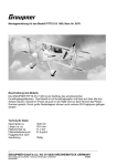
Montageanleitung für das Modell INSPIRATION
Best.-Nr. 6170
Beschreibung des Modells
Die Graupner INSPIRATION ist ein Sportjet der Superlative, der für puren Spaß am Kunstfliegen steht. Der hohe
Vorfertigungsgrad ist Garant für schnelles und einfaches fertig stellen des Modells. Sämtliche Ruder sind
angeschlagen und die Ruderhörner eingeklebt. Durch die verwendeten Kugelgelenke ergibt sich eine spielfreie
und präzise Anlenkung, die dem Piloten eine sehr exakte und direkte Steuerung ermöglicht. Die geschlossene
Luftführung sorgt für eine direkte und leistungssteigernde Luftzufuhr der Turbine. Alle zu verklebenden Spanten
sind bereits eingeklebt. Fertig lackiert in aufwendigem Sportjet Design.
Technische Daten
Spannweite ca.
Länge ü.a. ca.
Fluggewicht je nach
Ausrüstung
Antrieb
1605 mm
1920 mm
8200 g
G-BOOSTER 80 Best.- Nr.6814
GRAUPNER GmbH & Co. KG D-73230 KIRCHHEIM/TECK GERMANY
Keine Haftung für Druckfehler. Technische Änderungen vorbehalten!
Made in Thailand
1
07/2009
Die Sicherheitshinweise und die Anleitung müssen
sorgfältigst, gelesen und werden !!!
Wichtiger Hinweis:
Der Bau dieses Modells setzt hohe bautechnische und fliegerische
Grundkenntnisse voraus. Der Umgang mit einem Strahltriebwerk-Modell erfordert größte
Sorgfalt und besondere Fachkenntnisse.
Bitte beachten Sie die Sicherheitshinweise in der Bedienungsanleitung.
Bitte achten Sie auf die Vollständigkeit der Bedienungsanleitungen.
Herstellererklärung der Fa. Graupner GmbH & Co KG
Inhalt der Herstellererklärung:
Sollten sich Mängel an Material oder Verarbeitung an einem von uns in der Bundesrepublik Deutschland
vertriebenen, durch einen Verbraucher (§ 13 BGB) erworbenen Gegenstand zeigen, übernehmen wir, die Fa.
Graupner GmbH & Co KG, Kirchheim/Teck im nachstehenden Umfang die Mängelbeseitigung für den
Gegenstand.
Rechte aus dieser Herstellererklärung kann der Verbraucher nicht geltend machen, wenn die Beeinträchtigung
der Brauchbarkeit des Gegenstandes auf natürlicher Abnutzung, unsachgemäßer Verwendung (einschließlich
Einbau) oder Einwirkung von außen beruht.
Diese Herstellererklärung lässt die gesetzlichen oder vertraglich eingeräumten Mängelansprüche und –rechte des
Verbrauchers aus dem Kaufvertrag gegenüber seinem Verkäufer (Händler) unberührt.
Umfang der Garantieleistung
Im Garantiefall leisten wir nach unserer Wahl Reparatur oder Ersatz der mangelbehafteten Ware. Weitergehende
Ansprüche, insbesondere Ansprüche auf Erstattung von Kosten im Zusammenhang mit dem Mangel (z.B. Ein/Ausbaukosten) und der Ersatz von Folgeschäden sind – soweit gesetzlich zugelassen – ausgeschlossen.
Ansprüche aus gesetzlichen Regelungen, insbesondere nach dem Produkthaftungsgesetz, werden hierdurch
nicht berührt.
Voraussetzung der Garantieleistung
Der Käufer hat den Garantieanspruch schriftlich unter Beifügung des Originals des Kaufbelegs (z.B. Rechnung,
Quittung, Lieferschein) und dieser Garantiekarte geltend zu machen. Er hat zudem die defekte Ware auf seine
Kosten an die folgende Adresse einzusenden:
Fa. Graupner GmbH & CO KG, Serviceabteilung,
Henriettenstr.94 -96, D 73230 Kirchheim/Teck
Der Käufer soll dabei den Material- oder Verarbeitungsfehler oder die Symptome des Fehlers so konkret
benennen, dass eine Überprüfung unserer Garantiepflicht möglich wird.
Der Transport des Gegenstandes vom Verbraucher zu uns als auch der Rücktransport erfolgen auf Gefahr des
Verbrauchers.
Gültigkeitsdauer
Diese Erklärung ist nur für während der Anspruchsfrist bei uns geltend gemachten Ansprüche aus dieser
Erklärung gültig. Die Anspruchsfrist beträgt 24 Monate ab Kauf des Gerätes durch den Verbraucher bei einem
Händler in der Bundesrepublik Deutschland (Kaufdatum). Werden Mängel nach Ablauf der Anspruchsfrist
angezeigt oder die zur Geltendmachung von Mängeln nach dieser Erklärung geforderten Nachweise oder
Dokumente erst nach Ablauf der Anspruchsfrist vorgelegt, so stehen dem Käufer keine Rechte oder Ansprüche
aus dieser Erklärung zu.
Verjährung
Soweit wir einen innerhalb der Anspruchsfrist ordnungsgemäß geltend gemachten Anspruch aus dieser Erklärung
nicht anerkennen, verjähren sämtliche Ansprüche aus dieser Erklärung in 6 Monaten vom Zeitpunkt der
Geltendmachung an, jedoch nicht vor Ende der Anspruchsfrist.
Anwendbares Recht
Auf diese Erklärung und die sich daraus ergebenden Ansprüche, Rechte und Pflichten findet
ausschließlich das materielle deutsche Recht ohne die Normen des Internationalen Privatrechts
sowie unter Ausschluss des UN-Kaufrechts Anwendung.
Sicherheitshinweise und Warnungen für
Modelle mit Strahltriebwerk
GRAUPNER GmbH & Co. KG D-73230 KIRCHHEIM/TECK GERMANY
Keine Haftung für Druckfehler. Technische Änderungen vorbehalten!
Made in Thailand
2
07/2009
Vor dem Versuch der ersten Inbetriebnahme muss die gesamte Betriebs- und Montageanleitung
sorgfältig gelesen und verstanden werden. Diese Hinweise sind Teil der Bedienungsanleitung und
müssen zusammen mit der Bedienungsanleitung sorgfältig aufbewahrt und im Falle einer Weitergabe
dem nachfolgenden Benutzer unbedingt mit ausgehändigt werden.
Die Inbetriebnahme des Modells kann äußerst gefährlich sein. Insbesondere im Zusammenhang mit
dem Modellstrahltriebwerk Graupner G-Booster 80/G-Boster 120/G-Booster 160 sind
Geschwindigkeiten über 350 km/h erreichbar. Die Graupner Modellstrahltriebwerke entwickeln am
Motorengehäuse Temperaturen von bis zu 500°C (Celsius) und am Abgasstrahl 720°C. Da es sich um
einen richtigen Jet-Antrieb handelt sind unbedingt die Anleitung und die Warnhinweise im
Zusammenhang mit dem Strahltriebwerk zu beachten.
Das Modell erfordert Fachkenntnis, Disziplin und regelmäßigen Service sowie Wartung, zu Ihrem
Schutz und zum Schutz anderer Personen. Wenn Sie das Modell bauen und betreiben, müssen Sie
eingewiesen werden und die Inbetriebnahme des Modells, besonders im Zusammenhang mit dem JetAntrieb, sollte nur unter Aufsicht einer erfahrenen Person, die Sie unterstützen kann, Fehler zu
vermeiden, erfolgen. Fehler und Mängel beim Bau oder bei der Inbetriebnahme des Modells können zu
schweren Personenschäden oder gar zum Tod führen.
ACHTUNG!
Bevor Sie das Modellflugzeug in Betrieb nehmen, müssen Sie sich über die gesetzlichen
Bestimmungen informieren. Rechtlich gesehen ist ein Flugmodell ein Luftfahrzeug und unterliegt
entsprechenden Gesetzen, die unbedingt eingehalten werden müssen. Die Broschüre „Luftrecht für
Modellflieger“ stellt eine Zusammenfassung der deutschen Gesetze dar; sie kann auch beim
Fachhandel eingesehen werden. Bei Modellen mit Strahltriebwerken muss eine Aufstiegserlaubnis
vorliegen und es bestehen darüber hinaus auch Versicherungspflichten. Ferner müssen postalische
Auflagen, die die Fernlenkanlage betreffen, beachtet werden. Jedes Land hat hier eigene Regelungen,
die zu beachten sind. Haben Sie Ihre Fernsteuerung zugelassen/angemeldet, besteht ausreichender
Versicherungsschutz beim Betrieb von Modellflugzeugen, insbesondere Jet-Modellen.
WARNUNG!
Es liegt in Ihrer Verantwortung, andere vor Verletzungen zu schützen. Der Mindestabstand von
Wohngebieten für die Sicherheit von Personen, Tieren und Gebäuden muss mindestens 1,5 km
betragen.
Halten Sie von Stromleitungen Abstand. Fliegen Sie das Modell nicht bei schlechtem Wetter mit
niedriger Wolkendecke oder bei Nebel. Fliegen Sie nie gegen direktes Sonnenlicht. Sie könnten
sonst den Sichtkontakt zum Modell verlieren. Um Zusammenstöße mit richtigen, bemannten oder
unbemannten Flugzeugen zu vermeiden, landen Sie Ihr Modell sofort, wenn sich ein manntragendes
Flugzeug nähert.
Beim Betrieb mit Strahltriebwerk Graupner G-Booster 80/G-Boster 120/G-Booster 160 müssen
Personen oder Tiere folgende Sicherheitsabstände zur Turbine einhalten:
Vor der Turbine
An der Seite der Turbine
Hinter der Turbine
4,5 m
7,5 m
4,5 m
WARNUNG!
Die Inbetriebnahme und der Betrieb des Modells unter Einfluss von Alkohol, Drogen, Medikamenten,
etc. ist absolut verboten. Der Betrieb darf nur bei bester körperlicher, geistiger
Verfassung/Konzentration erfolgen. Dies gilt sowohl für den Betreiber als auch für seinen Helfer.
WARNUNG!
Das Modellflugzeug ist für den Modellflug entworfen und ist für keinen anderen Verwendungszweck
geeignet. Das Modell nicht für Personen, Güter oder auf andere Weise verwenden, sondern
ausschließlich für den Modellflug, da andere Verwendungszwecke zu Personenschäden oder Tod
führen können.
GRAUPNER GmbH & Co. KG D-73230 KIRCHHEIM/TECK GERMANY
Keine Haftung für Druckfehler. Technische Änderungen vorbehalten!
Made in Thailand
3
07/2009
WARNUNG!
Abweichungen von den Anweisungen dieser Anleitung, die Verwendung von anderen Teilen oder
Materialien und Änderungen im Aufbau wirken sich möglicherweise nachteilig auf die Funktionalität des
Flugmodells aus und müssen daher unbedingt vermieden werden.
WARNUNG!
Der Betrieb des Modells darf nur unter genauer Befolgung der Anweisungen im Hinblick auf die
Schwerpunktebenen und die Einstellung der Ruder erfolgen. Die vorgeschriebenen Einstellungen sind
zu beachten. Vor dem Start des Modells, müssen alle Funktionen und alle Ruder sowie die
Fernsteuerungsreichweite bei eingeschalteter Fernsteuerungsanlage ohne ausgezogene Antenne
überprüft werden. Dieser Betriebscheck muss bei laufender Turbine wiederholt werden, dabei sollte
das Modell eine andere Person festhalten. Darüber hinaus sind die Hinweise der
Fernsteuerungsanlage zu beachten.
AUSSCHLUSS VON HAFTUNG UND SCHÄDEN
Sie haben einen Bausatz erworben, aus dem - mit entsprechend geeignetem Zubehör - siehe
Bauanleitung vom Modell, ein funktionsfähiges RC-Modell fertiggestellt werden kann. Sowohl
die Einhaltung der Montage- und Betriebsanleitung im Zusammenhang mit dem Modell als auch
die Bedienung und Installation, Betrieb und Wartung der Fernsteuerungsanlagen können von
der Firma GRAUPNER nicht überwacht werden. Daher übernimmt die Firma GRAUPNER
keinerlei Haftung für Verluste, Schäden oder Kosten, die sich aus dem fehlerhaften Betrieb, aus
fehlerhaftem Verhalten bzw. in irgendeiner Weise mit vorgenanntem zusammenhängend
ergeben. Soweit vom Gesetzgeber nicht zwingend vorgeschrieben, ist die Verpflichtung der
Firma GRAUPNER zur Leistung von Schadensersatz, aus welchen Gründen auch immer
ausgeschlossen (inkl. Personenschäden, Tod, Beschädigung von Gebäuden sowie auch
Schäden durch Umsatz- und Geschäftsverlust, durch Geschäftsunterbrechung oder andere
indirekte oder direkte Folgeschäden). Die Gesamthaftung ist unter allen Umständen beschränkt
auf den Betrag, den Sie tatsächlich für dieses Modell gezahlt haben.
DIE INBETRIEBNAHME UND DER BETRIEB DES MODELLS ERFOLGT EINZIG UND ALLEIN AUF
GEFAHR DES BETREIBERS.
Sie bekräftigen, dass GRAUPNER das Befolgen der Anweisungen in diesem Betriebshandbuch – bzgl.
Aufbau, Betrieb, Einsatz des Flugzeugs und Einsatz der Fernsteuerungsanlage – nicht überwachen
und kontrollieren kann. Von Seiten GRAUPNER wurden weder Versprechen, Vertragsabsprachen,
Garantien oder sonstige Vereinbarungen gegenüber Personen oder Firmen bezüglich der Funktionalität
und der Inbetriebnahme des Modells gemacht. Sie als Betreiber haben sich beim Erwerb dieses
Modells auf Ihre eigenen Fachkenntnisse und Ihr eigenes Urteilsvermögen zu verlassen.
WEITERE SICHERHEITSHINWEISE
Überprüfung vor dem Start
Vor jedem Einsatz ist die korrekte Funktion und Reichweite zu überprüfen. Dazu ist der Sender
einzuschalten, ebenso der Empfänger. Senderantenne nicht auszuziehen. Aus entsprechendem
Abstand vom Modell ist zu kontrollieren, ob alle Ruder einwandfrei funktionieren und in der richtigen
Richtung ausschlagen.
Diese Überprüfung ist bei laufendem Triebwerk wiederholen, während ein Helfer das Modell festhält.
Beim erstmaligen Betreiben eines Flugmodells ist eindringlich zu empfehlen, einen Starthelfer mit
entsprechender Erfahrung hinzuzuziehen, der beim Zusammenbau oder Betrieb entstandene
Schwachstellen oder Fehlerquellen, die übersehen wurden, erkennt.
Die Angaben zur Schwerpunktlage und zu Ruderausschläge sind unbedingt zu beachten! Das Modell
muss entsprechend justiert werden.
Warnungen müssen unbedingt beachtet werden. Sie beziehen sich auf Dinge und Vorgänge, die
bei einer Nichteinhaltung zu schweren - in Extremfällen zu tödlichen Verletzungen oder
bleibenden Schäden führen können.
GRAUPNER GmbH & Co. KG D-73230 KIRCHHEIM/TECK GERMANY
Keine Haftung für Druckfehler. Technische Änderungen vorbehalten!
Made in Thailand
4
07/2009
Sie alleine sind
Strahltriebwerkes.
verantwortlich
für
den
sicheren
Betrieb
Ihres
Modells
und
des
• Um Gehörschäden beim Betrieb eines Jetmodells mit einer Turbine zu vermeiden, empfehlen wir
immer einen Gehörschutz zu tragen!
• Modelle mit Strahltriebwerk dürfen nie in geschlossenen Räumen, wie beispielsweise im Keller, in
Garagen, in Hallen usw. betreiben werden. Strahltriebwerke entwickeln sehr hohe
Abgastemperaturen + 500° C und höher.
• Modell nur im Freien betreiben
• Nicht beteiligte, die nicht zur Inbetriebnahme des Modells benötigt werden, müssen sich in
ausreichendem Sicherheitsabstand aufhalten. Bei Betrieb des Modells mit einem Strahltriebwerk nie
in den heißen Abgasstrahl hineinschauen, hineinfassen oder sich darin bewegen.
• Bei laufendem Strahltriebwerk niemals mit der Hand näher als 15 cm in den Bereich des
Ansaugtrichters fassen. Gegenstände, Kleidungsstücke, Tiere, Kinder usw. fernhalten. In diesem
Bereich herrscht ein extremer Sog, der blitzschnell die Hände, Finger oder andere Gegenstände
erfassen kann. Seien Sie sich dieser Gefahrenquelle stets bewusst!
• Vor Inbetriebnahme alle nicht fixierten Teile im Bereich des Ansaugkanals entfernen. Dies gilt auch
für Reinigungstücher, Schrauben, Muttern, Kabel oder andere Materialien. Insbesondere ist
sicherzustellen, dass sich im Ansaugkanal keine losen Teile wie z. B. Bauabfälle, Schrauben oder
Schleifstaub befinden. Nicht gesicherte Teile können die Turbine beschädigen und/oder zu
Verletzungen führen.
• Beim Betrieb mit einem Strahltriebwerk stets darauf achten, dass sich in der Laufebene des
Triebwerks keine Personen, Tiere oder bewegliche Gegenstände aufhalten (Gefahrenbereich!).
• Luftschrauben und generell alle sich drehenden Teile, die durch einen Motor oder dergleichen
angetrieben werden, stellen eine ständige Verletzungsgefahr dar. Sie dürfen mit keinem Körperteil
berührt werden. Eine schnelldrehende Luftschraube kann z. B. einen Finger abschlagen.
• Bei niedrigen Außentemperaturen können die Steckkupplungen der Gas-/Betankungs- und
Startvorrichtung einfrieren. Keinesfalls mit körperlicher Gewalt die Einfrierungen beseitigen.
• Jeder Betreiber hat sich so zu verhalten, dass die öffentliche Sicherheit und Ordnung, insbesondere
anderer Personen, Lebewesen und Gegenstände, sowie den Örtlichkeiten entsprechende
Regelungen nicht verletzt werden.
• Turbinenkraftstoff ist giftig! Nicht in Hautkontakt bringen! Eine Aufbewahrung ist nur in deutlich
gekennzeichneten Behältern und außerhalb der Reichweite von Kindern zulässig.
• Strahlgetriebene Modelle erreichen sehr hohe Spitzengeschwindigkeiten, deshalb nur bei genügend
großem Luftraum/Flugsektor und bei bester Sicht betreiben. Nicht bei tief hängenden Wolken den
Flugbetrieb aufnehmen. Nicht ins grelle Sonnenlicht fliegen. Ein Modell kann innerhalb von
Sekunden außer Sichtweite geraten. Manntragenden Fluggeräten oder anderen sich annähernden
Fluggeräten ist stets auszuweichen! Um jedes Risiko zu vermeiden, Modellturbine abstellen und das
Modell schnellstmöglich landen. Bemannte Fluggeräte und Menschenleben haben erste Priorität.
• Ein Betrieb darf nur bei bester körperlicher und geistiger Verfassung/Konzentration erfolgen.
• Kraftstoff ist leicht entzündlich und brennbar, fernhalten von offenem Feuer, übermäßiger Wärme,
Quellen von Funkenbildung - in der direkten Umgebung von Kraftstoff/Gas oder Kraftstoffdämpfen
darf nie geraucht werden.
GRAUPNER GmbH & Co. KG D-73230 KIRCHHEIM/TECK GERMANY
Keine Haftung für Druckfehler. Technische Änderungen vorbehalten!
Made in Thailand
5
07/2009
Beim Betrieb eines Strahltriebwerks muss unbedingt ein funktionsfähiger CO 2-Feuerlöscher - kein
Pulverlöscher!!! und eine Löschdecke bereit stehen. Brennbare und leicht entzündliche
Gegenstände, wie Treibstoffkanister, Gasflaschen aus dem Strahlbereich der Turbine entfernen →
Brandgefahr, auch bei sommerlicher Trockenheit (Gras, Rasen, Fruchtfelder usw.).
• Eine Strahlturbine entwickelt beim Betrieb Hitze und sehr hohe Arbeitstemperaturen, die auch nach
Stillstand und nach der Abkühlphase noch höher als 80° C sein können. Verbrennungsgefahr!
• Eine in Betrieb genommene Turbine keinesfalls berühren. Nie in Ansaugluft und Abgasstrahl fassen.
• Nach dem Betrieb bzw. vor dem Transport im KFZ ist Resttreibstoff komplett abzutanken bzw. das
Restgas entweichen zu lassen. Beim Ablassen von Restgas können bei Körper-/Hautkontakt
Erfrierungen auftreten. Generelles Fernhalten von offenen Flammen (Feuerzeug, offenes Licht und
jegliche Art brennbarer Genussmittel) - bei Be- und Enttankung kann Gas/Treibstoff austreten/laufen.
• Überprüfen Sie vor jeder Inbetriebnahme das Modell und alle angekoppelten Teile auf Funktion, Sitz
und Passung sowie auf mögliche Beschädigungen. Nur technisch einwandfreie Modelle in Betrieb
nehmen. Keinesfalls Kompromisse eingehen. Bei sichtbaren Beschädigungen und evtl. hörbaren
Lagerschäden oder anderen störenden abnormalen Systemgeräuschen ist der Startvorgang und
Betrieb zu unterlassen/einzustellen.
Die Turbine ist keinesfalls selbstständig zu zerlegen bzw. Instandsetzungsversuche zu
unternehmen. Bei Beschädigungen/Reparaturen muss die Turbine an die Service-Abteilung der
Firma GRAUPNER GmbH & Co. KG, Henriettenstr. 94 - 96, D - 73230 Kirchheim/Teck, eingesandt
werden - Reparatur erfordert Fachkenntnis und Spezialwerkzeug.
Bei eigenmächtigen Eingriffen erlischt jeglicher Garantieanspruch und Schadensersatz.
• Stets auf ausreichende Kraftstoffmenge im Tank achten. Der Tankinhalt kann nie restlos
ausgeflogen werden.
• Das überfliegen bzw. zufliegen auf Personen ist strengstens verboten.
• Nie auf Personen zufliegen.
• Auf ausreichenden Abstand zu Wohngebieten achten, mindestens 1,5 km Luftlinie. Am besten als
Club-Mitglied auf zugelassenem Modellflugplatz fliegen. Ausreichenden Abstand zu
Hochspannungsleitungen halten.
• Genügend Sicherheitsabstand zu Personen, Tieren und sonstigen Gegenständen einhalten,
insbesondere zu Kerosin und sonstigen entflammbaren Gegenständen.
• Während des Start- und Landevorgangs müssen die Start- und Landeflächen frei von unbefugten
Personen, Lebewesen und Gegenständen sein.
• Betreiben Sie Ihr Modell/Strahltriebwerk nie auf öffentlichen Straßen, Plätzen, Schulhöfen, Parkoder Spielplätzen usw. und sorgen Sie dafür, dass Sie es stets unter voller Kontrolle haben.
Der Bau und Betrieb dieses Modells setzt hohe bautechnische und fliegerische Erfahrung voraus. Das
weitgehend vorgefertigte Modell verlangt dennoch aufwendige und zu durchdenkende
Arbeitsschritte/Arbeiten - diese müssen sorgfältigst ausgeführt werden. Von derer einwandfreier
Ausführung hängt es ab, ob das Modell letztlich die vorgesehene Festigkeit und Flugeigenschaften
erhält.
GRAUPNER GmbH & Co. KG D-73230 KIRCHHEIM/TECK GERMANY
Keine Haftung für Druckfehler. Technische Änderungen vorbehalten!
Made in Thailand
6
07/2009
RC- Funktionen
Turbinenleistung (Gasknüppel)
Turbinensteuerung (Aus/Start/Auto-Stopp) 3-Stufenschalter
Querruder 2 Servos
Landeklappen 2 Servos
Höhenruder 2 Servos
Bugrad-Lenkung (gekoppelt zu Seitenruder)
Seitenruder über 1 Servo
Einziehfahrwerk
Radbremsen
Empfohlene Fernsteuerungen
GRAUPNER/JR-Computersysteme mc-20, mc-22, mc-24 mx-22 oder mx-24 im 35 MHz-Band (für
Deutschland, bzw. die in den Ländern vorgeschriebenen Frequenzbändern).
Benötigtes Zubehör (nicht im Bausatz enthalten)
2
1
2
2
Verlängerungskabel
Verlängerungskabel
Verlängerungskabel
Verlängerungskabel
Best.-Nr. 3935.105
Best.-Nr. 3935.65
Best.-Nr. 3935.32
Best.-Nr. 3935.18
1
1
1
Silikonschlauch
Silikonschlauch
Silikonschlauch
Best.-Nr. 1668.5
Best.-Nr. 1668.8
Best.-Nr. 1668.6
3
6
Halteplatte
Halteplatte
Best.-Nr. 610
Best.-Nr. 610.1
1
Klettband
Best.-Nr. 3368
1
1
Schrumpfschlauch
Schrumpfschlauch
Best.-Nr. 3391.3
Best.-Nr. 3391.4
1
Universal- Bindedraht
Best.-Nr. 540.300
1
Hochlast Servoarm
Best.-Nr. 3544
1
Stabantenne
Best.-Nr. 3536
1
Staubschutzsieb
Best.-Nr. 6814.21
1
1
Schlauchschnellverbinder
Schlauchschnellverbinder
Best.-Nr. 6800.2
Best.-Nr. 6800.1
1
1
G4 Stecker
Hochflexible Kupferlitze
Best.-Nr. 94642.1
Best.-Nr.3389
GRAUPNER GmbH & Co. KG D-73230 KIRCHHEIM/TECK GERMANY
Keine Haftung für Druckfehler. Technische Änderungen vorbehalten!
Made in Thailand
7
07/2009
Benötigtes Werkzeug (nicht im Bausatz enthalten)
1
1
1
1
1
1
1
1
1
1
Dremel Stylus
Dremel Driver
Bohrer 2mm
Schraubendreher Kreuzschlitz
Rundfeile Durchmesser 6
Biegevorichtung
Devcon 5 min Epoxy
Sekundenkleber dickflüssig
Sekundenkleber dünnflüssig
Holzleim
Best.-Nr. D1100-15
Best.-Nr. D1120-8
Best.-Nr. 43
Best.-Nr. 961.28
Best.-Nr. 5823
Best.-Nr. 5822
Best.-Nr.958.60
Benötigte RC- Komponenten(nicht im Bausatz enthalten)
Variante 1
1
1
2
2
4
2
1
1
1
Empfängerstromversorgung
Empfänger
Empfängerakkus
Servos DS 3328
Servo DS 8411
Einwege Absperrventil
G-Booster 80
Fahrwerkmechanik
Geschleppte Federbeine
Best.-Nr. 3052
Best.-Nr. 3177
Best.-Nr. 98981
Best.-Nr. 5157
Best.-Nr. 5151
Best.-Nr. 5171
Best.-Nr. 6814
Best.-Nr. 179
Best.-Nr. 174.1
Variante 2
1
1
2
2
4
2
1
1
1
Empfängerstromversorgung
Empfänger
Empfängerakkus
Servos DS 3328
Servos DES 806 BB, MB
Einwege- Absperrventil
G-Booster 80
Fahrwerkmechanik
Geschleppte Federbeine
Best.-Nr. 3052
Best.-Nr. 3177
Best.-Nr. 7661.2
Best.-Nr. 5157
Best.-Nr. 7952
Best.-Nr. 5171
Best.-Nr. 6814
Best.-Nr. 179
Best.-Nr. 174.1
Alle Teile in der Anleitung und in der Stückliste, die
mit Best.-Nr. angegeben werden, sind nicht im
Bausatz enthalten
GRAUPNER GmbH & Co. KG D-73230 KIRCHHEIM/TECK GERMANY
Keine Haftung für Druckfehler. Technische Änderungen vorbehalten!
Made in Thailand
8
07/2009
Montageanleitung
Tank
1. Bohren Sie in einen der beiden Tankdichtungen (1) die dritte angesenkte Durchführung
2. Beim Einschieben der Messingrohre gehen Sie wie auf den Bildern zu sehen vor:
Zuerst das Überlaufrohr (2), dann den Tankdeckel (3) aufschieben. Das Betankungsrohr (4) bei ca. 30-35mm
(wie auf Bild mit Biegevorrichtung Best.-Nr. 43) abbiegen und in die Tankdichtung (1) einschieben. Das
Pendelrohr (5) einführen und den Tankdeckel (3) beschriften, Ü für Überlauf, P für Pendel, T für Tanken.
GRAUPNER GmbH & Co. KG D-73230 KIRCHHEIM/TECK GERMANY
Keine Haftung für Druckfehler. Technische Änderungen vorbehalten!
Made in Thailand
9
07/2009
3. Die Tankdeckelgegenplatte (6) aufschieben und die Rohre ausrichten. Darauf achten, dass das Überlaufrohr
ca. 1mm herausragt. Nun die Inbusschraube (7) zum Quetschen der Dichtung eindrehen, aber nicht anziehen.
4. Schieben Sie auf das Filztankpendel (8) den
Kerosinschlauch (9) und auf Gesamtmaß 200mm
ablängen. Für das Ent- und Betanken ein Stück
Schlauch mit 75mm ablängen. Die Schläuche auf
die Messingrohre aufschieben und mit Bindedraht
sichern. Tipp : Den Bindedraht 2 mal
herumwickeln und dann verdrillen, um eine
bessere Abdichtung zu erreichen.
GRAUPNER GmbH & Co. KG D-73230 KIRCHHEIM/TECK GERMANY
Keine Haftung für Druckfehler. Technische Änderungen vorbehalten!
10
Made in Thailand
07/2009
5. Den Tankdeckel in den rechten Tank (10) einschieben und festziehen
6. Montieren Sie den für den linken Tank (11) den Tankdeckel das Überlauf- und Pendelrohr. Hier wird kein
drittes Rohr benötigt, da die Tanks in Reihe geschaltet werden. Gehen Sie nun wie beim ersten
Tankdeckel vor. Achten Sie darauf, dass die Tankdeckel wie auf dem Bild ausgerichtet sind, dies
vereinfacht das Anschließen der Schläuche.
GRAUPNER GmbH & Co. KG D-73230 KIRCHHEIM/TECK GERMANY
Keine Haftung für Druckfehler. Technische Änderungen vorbehalten!
11
Made in Thailand
07/2009
7. Schließen Sie die beiden Tanks zusammen. Ein
Verbindungsschlauch (12) vom rechten Tank
(Überlauf), auf linken Tank (Pendel). Mit dem Rest
des Schlauches verbinden Sie die Tanks noch
einmal, um die Dichtheit zu überprüfen. Sichern Sie
die Schläuche mit Bindedraht. Um die Dichtheit zu
prüfen, blasen Sie in das Rohr das später zum
Tanken verwendet wird, besprühen Sie die
Tanks vorher mit Glasreiniger, o.ä. das leicht zu
schäumen beginnt, da sich an den Undichten
Stellen Blasen bilden. So erkennen Sie am
schnellsten eine Undichtigkeit an den Tanks.
8. Die zusammengeschlossenen Tanks von unten in den Rumpf (13) einschieben und mit Inbusschrauben (14)
verschrauben.
9. Für die Turbinenbretthalterung (15) muss die
Aussparung geöffnet werden
GRAUPNER GmbH & Co. KG D-73230 KIRCHHEIM/TECK GERMANY
Keine Haftung für Druckfehler. Technische Änderungen vorbehalten!
12
Made in Thailand
07/2009
10. In die Halterung (15) die Einschlagmutter M3 (16) montieren und mit Devcon 5 min Epoxy Best.-Nr. 961.28
verkleben. Im selben Arbeitsgang kann die Halterung in den Spant eingeklebt werden.
11. Während des Aushärtens des Klebstoffes das
Turbinenbrett (17) mit Inbusschraube (18)
montieren, um die Passung zu gewährleisten.
Den Überlaufschlauch (19) vom rechten Tank bei
ca. 250 - 270 mm abschneiden, den
Tankpendelschlauch(20) des rechten Tankes
sollte nach dem Abschneiden min. 270mm lang
sein. Den bei der Turbine beiliegenden
Tanknippel (21) auf den Schlauch aufschieben.
Die Bohrung anzeichnen und mit 5mm bohren.
Den Anschlussnippel mit Unterlegscheibe (22)
und Mutter (23) in der Bohrung montieren.
GRAUPNER GmbH & Co. KG D-73230 KIRCHHEIM/TECK GERMANY
Keine Haftung für Druckfehler. Technische Änderungen vorbehalten!
13
Made in Thailand
07/2009
Turbinenbrett
12. Montieren Sie die Kerosinpumpe (24) mit Kabelbinder (25) am Turbinenbrett. Die Befestigungsschraube des
Turbinenbrettes ist gleichzeitig auch die Befestigung für den Y- Verbinder (26). 4 Unterlegscheiben (27) unter
den Y Verbinder legen, um etwas Abstand zum Turbinenbrett zu erhalten. Als Platzhalter etwas Restschlauch
auf den Ansaugnippel der Pumpe schieben. Den Kraftstofffilter (28) wie in der Turbinenanleitung beschrieben
zusammensetzen und am Brett mit einem Kabelbinder (29) montieren.
GRAUPNER GmbH & Co. KG D-73230 KIRCHHEIM/TECK GERMANY
Keine Haftung für Druckfehler. Technische Änderungen vorbehalten!
14
Made in Thailand
07/2009
13. Den Filter an der Pumpe und am Y- Verbinder anschließen. Montieren Sie nun die Shut- Off- Ventile (30und
31). Das untere Ventil auf dem Bild ist das Startventil ( START valve 4-3)
Tipp: Um den Schläuchen (32), die beim Einbau entstandene Spannung zu nehmen, können die
Schläuche mit eine Heißluftföhn erwärmt werden, das verhindert ein Undicht werden an den
Steckverbindern.
14. Schließen Sie vom rechten Tank den Pendelschlauch an die Pumpe an. Nun die der Turbine beiliegenden
Schläuche für START (33) (3mm) und FUEL (32) ( Karftstoff 4mm) Kerosinleitungen an die Ventile anschließen.
Das Turbinenbrett kann montiert werden.
15. Den Absperrhahn (34)
anschließen
an das Tank Rohr
GRAUPNER GmbH & Co. KG D-73230 KIRCHHEIM/TECK GERMANY
Keine Haftung für Druckfehler. Technische Änderungen vorbehalten!
15
Made in Thailand
07/2009
Seitenruder
16. Um das Seitenruderservo plan befestigen zu können, müssen die Halterungen bündig geschliffen werden und
die Gummitüllen mit den Messinghülsen anders als normal montiert werden siehe Bild. Auf das Servo einen
Hochlast Servoarm (35) Best.-Nr. 3544 montieren
17. Montieren Sie das Seitenruderservo mit den dem Servo beiliegenden Schrauben im Rumpf. Fertigen Sie aus
Gewindestange (36), Gabelkopf (37), Muttern (38) und Kugelgelenkträger (39) das Seitenrudergestänge an.
18. Das Seitenrudergestänge am Servo einhängen und am Ruderhorn mit Inbusschraube (40) und Stopmutter (41)
verschrauben.
GRAUPNER GmbH & Co. KG D-73230 KIRCHHEIM/TECK GERMANY
Keine Haftung für Druckfehler. Technische Änderungen vorbehalten!
16
Made in Thailand
07/2009
Kabelverlegung des Seiten- und Höhenruderkabels
19. Zum Schutz vor Hitze ist es sinnvoll die Kabel der Seiten und Höhenruderservos in Silikonschlauch zu
verlegen. Für die Verlegung müssen die Kontakte aus dem Stecker herausgezogen werden. Hier mit
äußerster Vorsicht vorgehen, damit die Stecker ihre Funktion nicht verlieren. Heben Sie mit einem
Messer oder einer Stecknadel die Sicherungsfedern an, um dann den Kontakt nach hinten herauszuziehen.
20. Für den Anschluss der Höhenruderservos werden 2 Verlängerungskabel Best.-Nr. 3935.105 benötigt. Schieben
Sie auf die Verlängerungskabel jeweils einen Silikonschlauch Best.-Nr. 1668.5 5x7mm 190mm lang bis über die
Steckerbuchse auf (Bild). Lassen Sie die Buchse ca. 5mm herausstehen. In den Schlauch etwas Seife
geben, dies vereinfacht das Aufschieben auf die Buchse.
21. Am Seitenruderservo ein 50 mm langes Stück vom 5x7mm Schlauch bis ans Servogehäuse aufschieben.
Fassen Sie die drei Kabel zusammen und führen Sie diese in einen 8x12mm Schlauch Best.-Nr. 1668.8 mit
50mm Länge. Die Schläuche müssen überlappen. Beim Zusammenfassen der Kabel darauf achten, dass
die Kabel sauber übereinander liegen, da der Platz im Silikonschlauch gerade ausreicht.
GRAUPNER GmbH & Co. KG D-73230 KIRCHHEIM/TECK GERMANY
Keine Haftung für Druckfehler. Technische Änderungen vorbehalten!
17
Made in Thailand
07/2009
22. Ein 200mm langes Stück 6x9mm Silikonschlauch Best.-Nr.1668.6 ablängen und die Servokabel
hindurchführen. In den Stecker des Seitenruderservos die Kontakte einschieben und auf Verriegelung
überprüfen. Wichtig: Darauf achten, dass die Kontakte in der richtigen Reihenfolge eingeschoben
werden.
23. Ein Verlängerungskabel Best.-Nr.3935.65 an das Seitenruderkabel anschließen und ein 70mm langes Stück
Silikonschlauch 8x12mm Best.-Nr. 1668.8 darüber schieben. Den Rest des 6x9mm Silikonschlauches Best.Nr.1668.6 aufschieben.
24. Befestigen Sie die Kabel mit einer Halteplatte Best.-Nr.610.1 auf dem Boden des Seitenruderservos. Die
Buchsen der Höhenruderkabel werden in die Aussparungen im Seitenruderspant eingeklebt und mit je einer
Halteplatte Best.-Nr. 610 befestigt
GRAUPNER GmbH & Co. KG D-73230 KIRCHHEIM/TECK GERMANY
Keine Haftung für Druckfehler. Technische Änderungen vorbehalten!
18
Made in Thailand
07/2009
Bugfahrwerk
25. Das Bugfahrwerk (42) an die Mechanik (43)
montieren und in den Eingefahren Zustand bringen,
mit einem Kabelbinder in der Position halten. Die
Mechanik muss bündig zum Fahrwerksspant
positioniert werden. Die Bohrungen anzeichnen und
für die beiliegenden Schrauben (44) mit 2mm
vorbohren Das Fahrwerk mit dem Spant
verschrauben.
26. Die Augenschrauben (45) der Bugfahrwerksanlenkung müssen so gekürzt werden, dass sie bis Gewindeende
in den Hebelarm eingedreht werden können. Die Anlenkseile (46) in die Augenschrauben einführen, die
Quetschhülse (47) bis an die Augenschraube darüber schieben und das Ende des Anlenkseils in die Hülse
schieben. Die Hülse mit einer Zange zusammenquetschen. Die Hülse sollte so nahe wie möglich an den
Augenschrauben anliegen, dies verhindert im Betrieb ein Herumschlenkern der Anlenkung. Mit einem
3mm Schrumpfschlauch Best.-Nr. 3391.3 auf ca.60mm Länge das Anlenkseil versteifen.
GRAUPNER GmbH & Co. KG D-73230 KIRCHHEIM/TECK GERMANY
Keine Haftung für Druckfehler. Technische Änderungen vorbehalten!
19
Made in Thailand
07/2009
27. Wie beim Höhenruderservo die Laschen bündig schleifen und die Gummitüllen und Messinghülsen montieren.
Auf das Servo einen Hochlast Servoarm (35) Best.-Nr. 3544 montieren. Das Bugfahrwerkservo in der
Servohalterung festschrauben.
28. Bereiten Sie die Seilführung für die Bugfahrwerksanlenkung vor. Hierzu einen 4mm Schrumpfschlauch Best.Nr.3391.4 in der Mitte durchtrennen, dies müsste ein Maß von 120mm ergeben. In der Mitte also bei 60mm wird
der Schrumpfschlauch halb eingeschnitten und der Kabelbinder (25) eingeführt.
GRAUPNER GmbH & Co. KG D-73230 KIRCHHEIM/TECK GERMANY
Keine Haftung für Druckfehler. Technische Änderungen vorbehalten!
20
Made in Thailand
07/2009
29. Führen
Sie
die
Anlenkseile
durch
die
Schrumpfschläuche, den Kabelbinder in den
Einschnitt einschieben und zu einer U –Vorm
biegen und in den zweiten Schrumpfschlauch
einführen. Darauf achten, dass der Kabelbinder
beide Seiten gleich weit integriert ist
in
30. Montieren Sie die Gabelköpfe (37) mit den Augenschrauben (48). Die Gabelköpfe in den Servoarm (35)
einhängen. Die Anlenkschnüre straffen und mit einem Filzschreiber die Mitte der Augenschraubenbohrung am
Anlenkseil anzeichnen. Darauf achten, dass sich das Servo und das Bugrad in Mittelstellung befinden.
GRAUPNER GmbH & Co. KG D-73230 KIRCHHEIM/TECK GERMANY
Keine Haftung für Druckfehler. Technische Änderungen vorbehalten!
21
Made in Thailand
07/2009
31. Verfahren Sie bei der Montage wie in Bauabschnitt 26. Die Markierung mit dem Filzschreiber sollte sich in der
Augenschraube befinden.
32. Hängen Sie die Gabelköpfe in einen losen
Servoarm ein. Den Schrumpfschlauch der
Seilführung über die Augenschrauben schieben und
unter
Spannung
mit
einem
Heißluftföhn
verschrumpfen. Die Gabelköpfe in den am Servo
montierten Ruderarm umhängen und die Seile
nachstellen.
GRAUPNER GmbH & Co. KG D-73230 KIRCHHEIM/TECK GERMANY
Keine Haftung für Druckfehler. Technische Änderungen vorbehalten!
22
Made in Thailand
07/2009
Druckluftbrett
33. Die Einschlagmutter (16) in die Halterung einsetzen und verkleben.
34. Auf die Bugradschachtabdeckung (49) die Luftventile (50) Best.-Nr. 5171 (s. Abb.) montieren. Das rechte Ventil
ist das Bremsventil. Wie beim Turbinenbrett können den Schläuchen mit einem Heißluftföhn die Spannungen
genommen werden. Die Schläuche mit Universalbindedraht Best.-Nr.540.300 bündeln.
GRAUPNER GmbH & Co. KG D-73230 KIRCHHEIM/TECK GERMANY
Keine Haftung für Druckfehler. Technische Änderungen vorbehalten!
23
Made in Thailand
07/2009
Stabantenne
35. Sollte ein 35 MHz Empfänger eingebaut werden, sollte jetzt die Stabantenne Best.-Nr.3536 montiert werden.
GRAUPNER GmbH & Co. KG D-73230 KIRCHHEIM/TECK GERMANY
Keine Haftung für Druckfehler. Technische Änderungen vorbehalten!
24
Made in Thailand
07/2009
Schubrohr und Turbineneinbau
36. Mit drei Blechschrauben (51) den Trichter (52) am Schubrohr (53) montieren. Um eine gleichmäßige
Verteilung der Schrauben zu erhalten kann man sich an den Schrauben des Schubrohres orientieren.
Die Verschraubungen des Schubrohres mit Schraubensicherungslack Best.-Nr. 951 sichern.
37. Die Turbinenverkleidung (54) aussparen und außen anschleifen
GRAUPNER GmbH & Co. KG D-73230 KIRCHHEIM/TECK GERMANY
Keine Haftung für Druckfehler. Technische Änderungen vorbehalten!
25
Made in Thailand
07/2009
38. Die Turbinenverkleidung mit dem Trichter verkleben
und in den Rumpf einschieben. Schubrohr
einschieben und dann um 180 ° drehen.
39. Die Turbine Best.-Nr.6814 wie in der Turbinenanleitung beschrieben, einbauen. Für die Schläuche und Kabel
der Turbine Aussparungen in die Turbinenverkleidung fräsen.
GRAUPNER GmbH & Co. KG D-73230 KIRCHHEIM/TECK GERMANY
Keine Haftung für Druckfehler. Technische Änderungen vorbehalten!
26
Made in Thailand
07/2009
40. Die Kabel und Schläuche, die der Turbine (55)
Best.-Nr.6814 beiliegen können zwischen Tank und
Rumpfwand verlegt werden. Die Kabel und
Schläuche, wie in der Anleitung der Turbine
beschrieben, anschließen.
41. Das Staubschutzsieb Best.-Nr. 6814.21 montieren.
Die Luftführung (56) auf das Ende der Lufteinlässe
aufschieben und in die
Turbinenverkleidung
einlegen. Die Turbine im Spant mit Schrauben (44)
verschrauben. Turbinenabdeckungen abbohren und
zusammen mit Blechschrauben (51) im Spant
verschrauben.
GRAUPNER GmbH & Co. KG D-73230 KIRCHHEIM/TECK GERMANY
Keine Haftung für Druckfehler. Technische Änderungen vorbehalten!
27
Made in Thailand
07/2009
Verkabelung der Elektronik
42. Die Turbinenelektronik (57) gemäß Turbinenanleitung verkabeln. Der Turbinen- Akku (58) findet vor der
Turbinenelektronik Platz. Die Empfängerstromversorgung Best.-Nr.3052, den Empfänger Best.-Nr. 3177 und
den Schalter an der Innenseite der Lufteinlässe mit Klettband Best.-Nr.3368 befestigen. Den Empfänger, wie in
der Anleitung der Stromversorgung beschrieben, anschließen. Wenn Sie entsprechend vorgehen, können die
Servokabel der Tragflächenservos direkt in die Empfängerstromversorgung einstecken, die Schläuche für das
Fahrwerk und die Bremse werden mit einem Schlauchschnellverbinder Best.-Nr. 6800.2 4-3mm für Bremse und
einem Schlauchschnellverbinder Best.-Nr. 6800.1 4-4mm für das Fahrwerk verbunden.
43. Für den Druckluftanschluss kann entweder das bei der Fahrwerksmechanik beiliegende Rückschlagventil, oder
wie hier eine Schlauchverschlusskupplung Best.-Nr.6800.7 verwendet werden, die mit einer Halteplatte Best.Nr.610.1 befestigt wird.
GRAUPNER GmbH & Co. KG D-73230 KIRCHHEIM/TECK GERMANY
Keine Haftung für Druckfehler. Technische Änderungen vorbehalten!
28
Made in Thailand
07/2009
Ausbau Rumpfnase
44. Die Druckluftflasche (59) wird mit 30mm langen Stück Klettband Best.-Nr.3368 so weit wie möglich vorne in der
Rumpfnase (60) befestigt.
45. Die Empfängerakkus Best.-Nr. 98981 ebenfalls mit Klettband Best.-Nr.3368 in der Rumpfnase befestigen. Das
Klettband sollte über nahezu die ganze Länge des Akkus gehen.
46. Fertigen Sie zwei Kabel, zur um die Akkus mit der Empfängerstromversorgung zu verbinden. Hierzu müssen
nach Ablängen des Kabels (Hochflexible Kupferlitze) Best.-Nr.3389 die beiliegenden Stecker der
Stromversorgung und je 2 G4- Stecker Best.-Nr. 94642.1 angelötet werden. Die Rumpfnase mit 4mm
Inbusschrauben (61) am Rumpf verschrauben.
GRAUPNER GmbH & Co. KG D-73230 KIRCHHEIM/TECK GERMANY
Keine Haftung für Druckfehler. Technische Änderungen vorbehalten!
29
Made in Thailand
07/2009
Montage der Kabinenhaube
47. Den Kabinenhaubenrahmen (62) auf den Rumpf
schrauben
(Inbusschraube
(61)
)M4.
Die
Kabinenhaubenverglasung (63) grob zuschneiden
und über den Rahmen legen. Die Verglasung exakt
zuschneiden, so dass sie von oben eingeführt
werden kann. Wichtig: die Verglasung nicht zu
klein
zuschneiden.
Öfters
die
Passung
kontrollieren.
48. Die Verglasung vorne, hinten, rechts und links in der Mitte mit Sekundenkleber dünnflüssig Best.-Nr. 5822
fixieren. Haube abschrauben und von innen fertig verkleben. Darauf achten, dass der Rahmen sich nicht
verzieht. Öfters die Passung kontrollieren.
GRAUPNER GmbH & Co. KG D-73230 KIRCHHEIM/TECK GERMANY
Keine Haftung für Druckfehler. Technische Änderungen vorbehalten!
30
Made in Thailand
07/2009
Höhenleitwerk
49. Je drei der Servohaltebrettchen (64) für die Höhenruderservos zu einem zusammen kleben und an die Servos
Best.-Nr.5157 schrauben.
50. Die überflüssigen Servoarme abtrennen und die Haltebrettchen im Höhenleitwerk (65) einpassen. Montieren
Sie hierzu am besten die Rudergestänge. Fertigen Sie aus Gewindestange (66), Gabelkopf (37) und Muttern
(38) die Höhenrudergestänge an.
51. Die Innenlage aus Glasfasergewebe etwas anrauen und die Servos mit Devcon 5 min Epoxy Best.-Nr. 961.28
im Leitwerk verkleben.
GRAUPNER GmbH & Co. KG D-73230 KIRCHHEIM/TECK GERMANY
Keine Haftung für Druckfehler. Technische Änderungen vorbehalten!
31
Made in Thailand
07/2009
52. Überkleben Sie das Höhenleitwerk auf der Oberseite im Bereich des Rumpfes mit Klebebandstreifen, das
Leitwerk am Rumpf montieren und die Rumpfaußenkontur abzeichnen. Für die Servokabel die Öffnungen
ausfräsen und mit einer Feile schräg ausfeilen, so dass sich der Silikonschlauch ohne Spiel leicht ein und
ausführen lässt. Ein 140mm langes Stück 6x9mm Silikonschlauch Best.-Nr.1668.6 ablängen und die
Servokabel hindurchführen. Um den Silikonschlauch anzubringen, ist wie bei der Verkabelung des Rumpfes
vorzugehen.
53. In die Servoabdeckungen (67) für den Servoarm Öffnungen ausfräsen, und mit glasklarem Klebeband NiBe am
Höhenruder befestigen
GRAUPNER GmbH & Co. KG D-73230 KIRCHHEIM/TECK GERMANY
Keine Haftung für Druckfehler. Technische Änderungen vorbehalten!
32
Made in Thailand
07/2009
54. Das Höhenrudergestänge einhängen
55. Das Höhenleitwerk mit Inbusschrauben (68) auf den Rumpf montieren. Die Servokabel einstecken und die
Kabel in das Höhenruder einschieben.
GRAUPNER GmbH & Co. KG D-73230 KIRCHHEIM/TECK GERMANY
Keine Haftung für Druckfehler. Technische Änderungen vorbehalten!
33
Made in Thailand
07/2009
Tragfläche
56. Trennen Sie die Servohalterungen (69) für die Querruderservos aus, diese entweder mit Sekundenkleber
dünnflüssig Best.-Nr. 5822 heften und mit Sekundenkleber dickflüssig Best.-Nr. 5823 in die Ecken eine
Kleberaupe setzen. Oder mit Holzleim Best.-Nr.958.60. Darauf achten, dass Sie eine rechte und eine linke
Halterung herstellen.
57. Montieren Sie die Querruderservos in den Halterungen mit dem Abtriebsrad nach vorne. Auf die Servos je
einen Hochlast Servoarm Best.-Nr. 3544 montieren jedoch vorher auf einer Seite kürzen.
58. Die Halterungen mit den Servos im Flügel (70) mit Inbusschraube (71) montieren und das Servokabel durch die
Öffnung im Fahrwerksspant führen. Für die Querruderservos benötigen Sie Verlängerungskabel Best.-Nr.
3935.32.
GRAUPNER GmbH & Co. KG D-73230 KIRCHHEIM/TECK GERMANY
Keine Haftung für Druckfehler. Technische Änderungen vorbehalten!
34
Made in Thailand
07/2009
59. Montieren Sie die Rudergestänge am Servo und den Ruderhörnern. Fertigen Sie aus Gewindestange (72),
Gabelkopf (37), Muttern (38) und Kugelgelenkträger (39) das Querrudergestänge an.
60. Die Landeklappenservos mit je einem Hochlast Servoarm Best.-Nr. 3544 im Flügel montieren. Fertigen Sie aus
Gewindestange (73), Gabelkopf (37) und Muttern (38) die Höhenrudergestänge an. Für die Gestänge die
Durchführungen etwas vergrößern. Gestänge montieren und die Durchbrüche für die Gestänge anpassen. Für
die Landeklappenservos benötigen Sie Verlängerungskabel Best.-Nr. 3935.18.
61. Montieren Sie die Fahrwerksbeine Best.-Nr. 174.1 an die Mechaniken Best.-Nr. 173 und bringen Sie in den
Eingefahrenen Zustand, mit einem Kabelbinder (25), der um Zylinder und Bein geht, in der Position halten. Das
Fahrwerk in den Fahrwerkspant einlegen und zu den Aussparungen ausrichten. Für die Fahrwerksschrauben
mit 2mm vorbohren und das Fahrwerk im Spant montieren
GRAUPNER GmbH & Co. KG D-73230 KIRCHHEIM/TECK GERMANY
Keine Haftung für Druckfehler. Technische Änderungen vorbehalten!
35
Made in Thailand
07/2009
62. Für die Servokabel und Luftschläuche eine Durchführung ausfräsen. In die T- Verbinder die Luftschläuche
einstecken und die T- Verbinder mit Kabelbinder am Flügel befestigen.
63. Die Schläuche für Fahrwerk und Bremsen montieren und mit Universalbindedraht Best.-Nr. 540.300 am
Fahrwerksbein befestigen.
64. D
GRAUPNER GmbH & Co. KG D-73230 KIRCHHEIM/TECK GERMANY
Keine Haftung für Druckfehler. Technische Änderungen vorbehalten!
36
Made in Thailand
07/2009
Die Servo- und Fahrwerksabdeckung (74) mit Klasklarem Klebeband NiBe am Flügel befestigen
65. Den Flügel am Rumpf montieren, die Kabel und Schläuche einstecken. Bei den Kabeln am besten mit
eingeschaltetem Sender arbeiten, um die richtige Reihenfolge festzulegen. Die Kabel flach aufeinander legen
und mit Kabelbindern (29) zusammenfassen. Die Kabel können so nicht beim Einstecken vertauscht werden.
Stückliste
Pos.Nr.
1.
2.
3.
4.
5.
6.
7.
8.
9.
10.
11.
12.
13.
14.
15.
16.
17.
18.
19.
20.
21.
Benennung
Tankdichtungen
Überlaufrohre
Tankdeckel
Betankungsrohr
Pendelrohr
Tankdeckelgegenplatte
Inbusschraube
Filztankpendel
Kerosinschlauch
Tank rechts
Tank links
Verbindungsschlauch
Rumpf Inspiration
Inbusschraube
Turbinenbretthalterung
Einschlagmutter M3
Turbinenbrett
Inbusschraube
Überlaufschlauch
Tankpendelschlauch
Tanknippel
Anzahl
2
2
2
2
2
2
2
2
1
1
1
1
1
2
1
2
1
1
1
1
1
Material
Gummi
Messing
Aluminium
Messing
Messing
Aluminium
Stahl
Stahl- Filz
Kunststoff
GFK
GFK
Kunststoff
GFK
Stahl
Holz
Stahl
Holz
Stahl
Kunststoff
Kunststoff
Messing
Abmessung und Stärke in mm
4x3x45mm
4x3x90mm
4x3x90mm
M3 x 25
6x1000mm
6x140mm
Lackiert
M3x20mm
Frästeil
Frästeil
M3x18
6x260mm
6x270mm
Bei Turbine Best.-Nr. 6814 beiliegend
GRAUPNER GmbH & Co. KG D-73230 KIRCHHEIM/TECK GERMANY
Keine Haftung für Druckfehler. Technische Änderungen vorbehalten!
37
Made in Thailand
07/2009
22.
23.
24.
25.
26.
27.
28.
29.
30.
31.
Unterlegscheibe
Mutter
Kerosinpumpe
Kabelbinder
Y- Verbinder
Unterlegscheibe
Kraftstofffilter
Kabelbinder
Shut- Off- Ventile
Shut- Off- Ventile
1
1
1
3
1
4
1
1
1
1
Messing vernickelt
Messing
Stahl
Kunststoff
Spritzteil
Messing vernickelt
Aluminium
Kunststoff
Startventil
Kraftstoffventil
32. Kraftstoffschlauch
1
Kunststoff
33.
34.
35.
36.
37.
38.
39.
40.
41.
42.
43.
44.
45.
46.
47.
48.
49.
1
1
5
1
13
13
3
3
3
3
3
16
2
1
2
2
1
Kunststoff
Spritzteil
Spritzteil
Stahl
Stahl
Stahl
Kunststoff
Stahl
Stahl
Aluminium
Aluminium
Stahl
Aluminium
Stahl
Stahl
Stahl
Holz
Bremse und
Fahrwerk
Stahl
CFK
EdelstahlAluminium
CFK
Stahl
GFK
Elektronik
Litium Ionen
Kraftstoffschlauch Startkerosin
Absperrhahn
Hochlast Servoarm
Gewindestange
Gabelkopf
Mutter
Kugelgelenkträger
Inbusschraube
Stopmutter
Geschleppte Federbeine
Fahrwerkmechanik
Fahrwerksbefestigungsschrauben
Augenschrauben
Anlenkseile
Quetschhülse
Augenschrauben
Bugradschachtabdeckung
50. Einwegeabsperrventil
51. Blechschrauben
52. Trichter
2
7
1
53.
54.
55.
56.
57.
58.
Schubrohr
Turbinenverkleidung
Turbine
Luftführung
Turbinenelektronik
Turbinen- Akku
1
2
1
1
1
1
59.
60.
61.
62.
63.
64.
65.
66.
67.
68.
69.
70.
71.
72.
73.
74.
Druckluftflasche
Rumpfnase
Inbusschraube
Kabinenhaubenrahmen
Kabinenhaubenverglasung
Servohaltebrettchen
Höhenleitwerk
Gewindestange
Servoabdeckungen
Inbusschraube
Servohalterungen
Tragfläche
Inbusschraube
Gewindestange
Gewindestange
Servo- und Fahrwerksabdeckung
1
1
3
1
1
12
1
2
L+R
2
2
1
6
2
2
L+R
Bei Turbine Best.-Nr. 6814 beiliegend
M5 Bei Turbine Best.-Nr. 6814 beiliegend
Bei Turbine Best.-Nr. 6814 beiliegend
5x170mm NiBe
Bei Turbine Best.-Nr. 6814 beiliegend
7x3,2x0,5 Best.-Nr.560.30 NiBe
Bei Turbine Best.-Nr. 6814 beiliegend
3x100 NiBe
4-3 Bei Turbine Best.-Nr. 6814 beiliegend
4-4 Bei Turbine Best.-Nr. 6814 beiliegend
4mm Bei Turbine Best.-Nr. 6814
beiliegend
3mm Bei Turbine Best.-Nr. 6814
beiliegend
Bei Turbine Best.-Nr. 6814 beiliegend
Best.-Nr. 3544 NiBe
3x90mm
Fertigteil
M3
Fertigteil
M3x 16mm
M3
Frästeil Best.-Nr. 174.1
Frästeil Best.-Nr. 173
4x20mm
Bei Federbeine Best.-Nr. 174.1 beiliegend
0,65x1000mm
2x4mm
Fertigteil
Frästeil
4-4 Best.-Nr.5171 NiBe
2,9x9,5 Best.-Nr. 5877.10 NiBe
Fertigteil
Aluminium Blech
GFK
Stahl
GFK
Kunststoff
Holz
GFK
Stahl
GFK
Stahl
Holz
GFK
Stahl
Stahl
Stahl
GFK
Fertigteil
Fertigteil
Fertigteil Best.-Nr.6814 NiBe
Fertigteil
Bei Turbine Best.-Nr. 6814 beiliegend
Bei Turbine Best.-Nr. 6814 beiliegend
Bei Fahrwerkmechanik Best.-Nr. 173
beiliegend
Lackiert
M4x12mm
Lackiert
Klar
Frästeil
Lackiert
M3x45mm
Lackiert
M4x25mm
Frästeil
Lackiert
M3x10
M3x110
M3x70
Lackiert
NiBe = Nicht in Bausatz enthalten
GRAUPNER GmbH & Co. KG D-73230 KIRCHHEIM/TECK GERMANY
Keine Haftung für Druckfehler. Technische Änderungen vorbehalten!
38
Made in Thailand
07/2009
Schwerpunkt
175-185mm von Nasenleiste zu Rumpf – Flügelübergang.
Beim Testmodell geflogener Schwerpunkt
181mm
Ruderausschläge
Flugphase
Höhenruder
Seitenruder
+/- 30mm
+/- 30mm
+/- 30mm
0mm
Querruder außen
gemessen
+15mm /- 12mm
+15mm /- 12mm
+15mm /- 12mm
0mm
Landeklappen innen
gemessen
+/-0
Normal
Start
Landung
Phasentrimmung
Start
Phasentrimmung
Landung
EXPO Werte
Normal
EXPO Werte
Start
EXPO Werte
Landung
+/- 15mm
+/- 15mm
+/- 15mm
- 1,5mm
- 3,5mm
0mm
+ 2mm
- 45mm
15 %
15%
40%
0%
15%
25%
25%
0%
10%
25%
10%
0%
- 25mm
+ = Ausschlag nach oben
- = Ausschlag nach unten
Einfliegen des Modells
Voraussetzung für den erfolgreichen Erstflug ist ein nach Bauanleitung gebautes und
eingestelltes Modell.
Bevor Sie das Modell einfliegen, überprüfen Sie, ob alle Ruderanlenkungen spielfrei
eingebaut sind, evtl. Verschraubungen und Kontermuttern ggf. mit UHU schraubensicher,
Best.-Nr. 952, gesichert wurden. Das Einziehfahrwerk muss 100%ig funktionsfähig, im
ausgefahrenen Zustand verriegelt sein, damit die Turbine und das dazugehörige
Turbinensystem ordentlich arbeitet. Kontrollieren Sie, ob alle Ruderausschläge sowie der
Schwerpunkt entsprechend den Angaben eingestellt wurden. Führen Sie einen ausgiebigen
Reichweitentest mit laufender Turbine durch. Sind alle eingebauten Komponenten
ordnungsgemäß gesichert, können diese sich keinesfalls bei erhöht auftretenden
Beschleunigungen lösen, liegt der Schwerpunkt bei dem von Ihnen gebauten Modell
tatsächlich bei der Herstellerangabe von 175 – 185 mm von der Nasenleiste zum
Flügelübergang, arbeiten die Ruderausschläge in der gesteuerten Richtung
entsprechend, sind alle Akkus für Empfangsanlage/ Turbinenelektronik optimal
geladen, wurde die Empfängerantenne ordnungsgemäß verlegt?
-
Nun steht dem Erstflug nichts mehr im Wege.
-
Oft kann ein szenenorientierter Modellfliegerkollege beim Erstflug/Erststart der
Turbine hilfreich sein. Scheuen sie sich nicht, insbesondere als Turbineneinsteiger,
sich bei szenenbekannten Piloten Auskünfte einzuholen!
GRAUPNER GmbH & Co. KG D-73230 KIRCHHEIM/TECK GERMANY
Keine Haftung für Druckfehler. Technische Änderungen vorbehalten!
39
Made in Thailand
07/2009
Graupner
Assembly instructions for the INSPIRATION model aircraft
Order No. 6170
The model
The Graupner INSPIRATION is a superlative sport jet whose sole purpose is to provide unadulterated
fun and a great aerobatic performance. The kit is very highly pre-fabricated to ensure that the model
goes together quickly and easily. All the control surfaces are factory-hinged, and the horns are already
glued in place. Ball-links are employed to provide accurate, slop-free linkages, guaranteeing extremely
precise, direct control response for the pilot. The enclosed air duct directs air straight to the turbine for
maximum performance. All the fuselage formers are already bonded in place. The model is supplied
completely painted in a sophisticated Sportjet finish.
Specification
Wingspan approx.
Overall length approx.
All-up weight according to fittings
Turbine
1605 mm
1920 mm
8200 g
G-BOOSTER 80, Order No. 6814
It is essential to study the Safety Notes and these Building Instructions with the greatest care !!!
Important: the construction of this model requires a high level of technical knowledge, manual
skill and piloting experience. Operating a model with a jet engine calls for an extremely
circumspect approach and specialised technical expertise.
Please read and observe the safety notes in the operating instructions.
The turbine operating instructions are comprehensive and must be observed.
Manufacturer’s declaration from Graupner GmbH & Co KG
Contents of the manufacturer’s declaration:
If material defects or manufacturing faults should arise in a product distributed by us in the Federal
Republic of Germany and purchased by a consumer (§ 13 BGB), we, Graupner GmbH & Co. KG, D73230 Kirchheim/Teck, Germany, acknowledge the obligation to correct those defects within the
limitations described below.
The consumer is not entitled to exploit this manufacturer’s declaration if the failure in the usability of the
product is due to natural wear, use under competition conditions, incompetent or improper use
(including incorrect installation) or external influences.
This manufacturer’s declaration does not affect the consumer’s legal or contractual rights regarding
defects arising from the purchase contract between the consumer and the vendor (dealer).
Extent of the guarantee
If a claim is made under guarantee, we undertake at our discretion to repair or replace the defective
goods. We will not consider supplementary claims, especially for reimbursement of costs relating to the
defect (e.g. installation / removal costs) and compensation for consequent damages unless they are
allowed by statute. This does not affect claims based on legal regulations, especially according to
product liability law.
Guarantee requirements
The purchaser is required to make the guarantee claim in writing, and must enclose original proof of
purchase (e.g. invoice, receipt, delivery note) and this guarantee card. He must send the defective
goods to us at his own cost, using the following address:
GRAUPNER GmbH & Co. KG D-73230 KIRCHHEIM/TECK GERMANY
Keine Haftung für Druckfehler. Technische Änderungen vorbehalten!
40
Made in Thailand
07/2009
Graupner GmbH & Co. KG, Service Department,
Henriettenstr. 94 - 96, D-73230 Kirchheim/Teck, Germany
The purchaser should state the material defect or manufacturing fault, or the symptoms of the fault, in
as accurate a manner as possible, so that we can check if our guarantee obligation is applicable.
The goods are transported from the consumer to us and from us to the consumer at the risk of the
consumer.
Duration of validity
This declaration only applies to claims made to us during the claim period as stated in this declaration.
The claim period is 24 months from the date of purchase of the product by the consumer from a dealer
in the Federal Republic of Germany (date of purchase). If a defect arises after the end of the claim
period, or if the evidence or documents required according to this declaration in order to make the claim
valid are not presented until after this period, then the consumer forfeits any rights or claims from this
declaration.
Limitation by lapse of time
If we do not acknowledge the validity of a claim based on this declaration within the claim period, all
claims based on this declaration are barred by the statute of limitations after six months from the time of
implementation; however, this cannot occur before the end of the claim period.
Applicable law
This declaration, and the claims, rights and obligations arising from it, are based exclusively on
the pertinent German Law, without the norms of international private law, and excluding UN
retail law.
Safety notes and warnings concerning
jet-powered models
Before you attempt to fly the model for the first time it is absolutely essential that you read right through
the operating and building instructions, and understand every part of the text. These notes are an
integral part of the operating instructions and should be stored away carefully together with the
instructions. If you ever dispose of the model, be sure to pass these documents on to the new owner.
Please note that operating this model is potentially an extremely hazardous activity. When powered by
a Graupner G-Booster 80 / G-Booster 120 / G-Booster 160 jet engine the model is capable of
airspeeds of 350 km/hr and more. The case temperature of Graupner turbines can be up to 500°C
(Celsius), and the exhaust gas temperature may even reach 720°C. These engines are genuine
turbines, and it is essential to study the instructions and warning notes supplied with your power plant
before you even attempt to run it.
In the interests of your own safety and that of others, the model must only be operated by experienced,
disciplined modellers with sufficient specialised expertise, and it must be serviced and maintained
regularly and competently. If you have little experience in building and operating models of this type, it
is vital that you enlist the help and advice of an experienced jet modeller if you are to avoid potentially
catastrophic errors; this applies in particular to the jet engine itself, which should only be run when an
experienced operator is present. With this model any defect or deficiency in its construction or
operation can result in serious personal injury or even death.
CAUTION!
Before you operate this model aircraft you must determine the local by-laws and regulations which
apply to you. In legal terms our models are classed as aircraft, and as such are subject to legal
regulations and restrictions which must be observed. Our brochure “Luftrecht für Modellflieger”
(Aviation Law for Model Flyers) contains a summary of all these rules as defined under German law.
Your local model shop should have a copy which you can read. Models powered by jet engines require
the landowner’s permission before flying. Third party insurance is mandatory. There are also Post
GRAUPNER GmbH & Co. KG D-73230 KIRCHHEIM/TECK GERMANY
Keine Haftung für Druckfehler. Technische Änderungen vorbehalten!
41
Made in Thailand
07/2009
Office regulations concerning your radio control system, and these must be observed at all times. The
rules vary from country to country; please refer to your RC system instructions for more details. Thirdparty insurance is a basic essential, and it is your responsibility to ensure that it covers you for the risks
involved in flying model jets.
WARNING!
It is your responsibility to protect others from possible injury. Keep a safe distance from residential
areas in order to protect people, animals and buildings: at least 1.5 km “as the crow flies”.
Keep well clear of high-tension overhead cables. Don’t fly the model in poor weather, especially when
there is low cloud cover or fog. Don’t fly the model directly into the sun, as you could easily lose
visual contact with it. To avoid collisions always keep well clear of full-size aircraft, whether manned or
unmanned. It is your responsibility to land immediately if a real aircraft approaches.
When operating the Graupner G-Booster 80 / G-Booster 120 / G-Booster 160 jet engine you must
keep people and animals a safe distance away. This means:
In front of the turbine
To the side of the turbine
Behind the turbine
4.5 m
7.5 m
4.5 m
WARNING!
Operating a model aircraft under the influence of alcohol or drugs is not permissible under any
circumstances. The operator of the model must be in full possession of his or her bodily and mental
faculties. This applies both to the operator and to his or her assistants.
WARNING!
Radio-controlled model aircraft may only be used for the purpose intended by the manufacturer. They
must never be used as machines for carrying people or goods, nor for any other purpose except as
model aircraft. Misuse of this model may result in serious personal injury or even death.
WARNING!
It is important not to make any modifications of any kind to the model. If you deviate from the
instructions, perhaps by using different components or materials, or by making changes to the
structural design, you may seriously affect the ability of the model aircraft to function correctly. Please
resist the temptation, and build the model exactly as directed.
WARNING!
Before you fly the model it is essential to check the Centre of Gravity and the control surface travels, as
stated in these instructions. These settings are very important, and our recommended values must be
observed. Before you fly the model, carry out a careful check of all the working functions and all the
control surfaces. Check the range of the radio control system with the transmitter aerial collapsed. If the
check is satisfactory, repeat it with the engine running, while an assistant holds the model securely.
Read the instructions supplied with your radio control system and make sure that you observe the
manufacturer’s recommendations.
LIABILITY EXCLUSION AND DAMAGES
You have acquired a kit which can be assembled into a fully working RC model when fitted out
with suitable accessories, as described in the building instructions in the kit. However, as
manufacturers, we at Graupner are not in a position to influence the way you build and operate
your model, and we have no control over the methods you use to install, operate and maintain
the radio control system components. For this reason we are obliged to deny all liability for
loss, damage or costs which are incurred due to the incompetent or incorrect application and
operation of our products, or which are connected with such operation in any way. Unless
otherwise prescribed by binding law, the obligation of the Graupner company to pay
compensation is excluded, regardless of the legal argument employed. This applies to personal
injury, death, damage to buildings, loss of turnover and business, interruption of business or
GRAUPNER GmbH & Co. KG D-73230 KIRCHHEIM/TECK GERMANY
Keine Haftung für Druckfehler. Technische Änderungen vorbehalten!
42
Made in Thailand
07/2009
other direct and indirect consequent damages. In all circumstances our total liability is limited
to the amount which you actually paid for this model.
BY OPERATING THIS MODEL YOU ASSUME FULL RESPONSIBILITY FOR YOUR ACTIONS.
It is important to understand that GRAUPNER is unable to monitor whether you keep to the instructions
contained in this operating manual regarding the construction, operation and maintenance of the
aircraft, nor whether you install and use the radio control system correctly. For this reason we at
GRAUPNER are unable to guarantee or provide a contractual agreement with any individual or
company that the model you have made will function correctly and safely. You, as operator of the
model, must rely upon your own expertise and judgement in acquiring and operating this model.
SUPPLEMENTARY SAFETY NOTES
Pre-flight checking
Before every session check that all the model’s working systems function correctly, and be sure to carry
out a range check. This is the procedure: switch on the transmitter, followed by the receiver. Leave the
transmitter aerial collapsed and walk away from the model. At the appropriate range check that all the
control surfaces work perfectly when you move the sticks.
Repeat the procedure with the engine running, while an assistant holds the model securely.
The first time you fly any new model aircraft we strongly recommend that you enlist the help of an
experienced modeller to help you check the model and offer advice while you are flying. He should be
capable of detecting potential weak points and errors.
Be certain to keep to the recommended CG position and control surface travels; if adjustments are
required, carry them out - don’t just “make do”.
Don’t ignore our warnings or those provided by other manufacturers. They refer to things and
processes which, if ignored, can result in fatal injury or permanent damage.
You alone are responsible for the safe operation of your radio-controlled model and its jet
engine.
•
•
•
•
•
•
•
•
•
Turbines may damage your hearing; always wear ear protectors when operating these engines.
Never run a jet engine in an enclosed space such as a workshop, garage, hall etc. Turbines
develop very high exhaust gas temperatures of +500°C and more, and therefore represent a
serious fire hazard.
This model must only be operated outdoors.
Persons not required directly to operate the model and turbine must be kept well clear of the model.
When the jet engine is running, never look, reach or walk into the area of the hot exhaust gas flow.
When the turbine is running keep your hands at least 15 cm away from the area of the intake
funnel. Keep all extraneous objects - clothing, animals, children etc. - well clear. The engine
develops a very powerful suction force in this area, which is perfectly capable of sucking a hand,
finger or other object into the spinning compressor in an instant. Keep this potential hazard in mind
at all times!
Before you run the engine, remove all loose objects from the area of the intake duct. This applies to
cleaning cloths, screws, nuts, cables and any other miscellaneous objects. Check in particular that
you have not left any small loose items in the inlet duct, such as waste materials from building the
model, odd screws or even sanding dust. Loose parts can very quickly enter the turbine and cause
serious damage or personal injury.
When running the jet engine always ensure that no persons, animals or movable objects are in the
plane of rotation of the engine (hazard zone!).
Propellers and other rotating parts which are powered by a motor constitute a constant hazard and
represent a real risk of injury. Don’t touch them with any part of your body. For example, a propeller
spinning at high speed can easily slice off a finger.
At low ambient temperatures the plug-in connections for the starting gas / fuel system may freeze or
bind; the starter mechanism may also tend to freeze up. Free the parts carefully - on no account
GRAUPNER GmbH & Co. KG D-73230 KIRCHHEIM/TECK GERMANY
Keine Haftung für Druckfehler. Technische Änderungen vorbehalten!
43
Made in Thailand
07/2009
use excessive force.
All model flyers should behave in such a way that the danger to people, other creatures and
property is minimised. Never act in any way which will disturb other modellers and prevent safe,
orderly flying at the site.
• Turbine fuel is toxic! Avoid skin contact at all times! Fuel must always be stored in clearly marked
containers, and kept out of the reach of children.
• Jet-powered models are capable of extremely high airspeeds, and for this reason they must only be
flown where there is plenty of open airspace, and where unrestricted vision is guaranteed. Do not
fly the model when there is low cloud cover, and never fly directly into the sun in bright conditions.
Since the model is so fast, within a few seconds it can fly completely out of sight of the pilot. Always
give way to full-size aircraft of any kind well before there is the remotest chance of collision. To
avoid all risks, stop the turbine and land the model as quickly as possible. Manned aircraft and
human life have top priority.
• Do not fly the model unless you are in the best of health, and are able to concentrate fully on the
activity.
• Turbine fuel is volatile and highly inflammable, and must be kept well away from open flames,
excessive heat and possible sources of sparks. Do not smoke anywhere near the area where fuel,
fuel vapours or gas may be expected.
Whenever you are operating a jet engine it is essential to keep a fully charged, correctly maintained
C02 fire extinguisher - not a powder-based type - to hand at all times, together with a fire blanket.
Flammable and volatile objects and materials, such as fuel containers and gas bottles, must be kept
well out of the range of the turbine’s hot exhaust area. Jet engines represent a serious fire hazard,
especially in dry Summer conditions (dry grass, stubble etc.).
• Jet engines develop great heat and run at very high temperatures; even when stopped and left to
cool down for a considerable period, some parts can still be hotter than 80°C. If you are unsure, you
can avoid painful burns simply by not touching the engine.
• Never touch any part of the turbine when it is running. Keep well clear of the area around the intake
and the exhaust.
• At the end of each session remove all traces of fuel remaining in the engine and tank, and allow
residual gas to dissipate before placing the model in your car. Note that escaping compressed gas
is extremely cold and can produce freeze burns, so avoid skin contact. At all times keep well clear
of open flames (cigarette lighters, matches etc.) when filling or draining fuel tanks, as gas or liquid
fuel may escape and cause a fire hazard.
• Every time you intend to operate your model check carefully that it and everything attached to it is in
good condition and undamaged. Do not fly the model unless you are confident that every part of it is
in perfect condition. Don’t be tempted to compromise your safety standards. If you detect visible
damage, or hear any abnormal system noises which might indicate bearing wear or some other
problem, cease operations immediately and locate and eradicate the fault.
•
•
•
•
•
•
•
•
Never attempt to dismantle or repair the turbine yourself. If the engine is damaged or requires
servicing, send it to the GRAUPNER Service Department, Henriettenstr. 94 - 96, D-73230
Kirchheim/Teck, Germany. All work on model turbines requires specialist knowledge and special
tools; don’t try it yourself.
Any attempt to interfere with the engine invalidates the guarantee, and we will deny any claim under
guarantee and any claim for damages in that case.
Be sure to keep an adequate supply of fuel in the tank. Don’t continue to fly the model until the tank
is drained dry.
It is absolutely prohibited to fly directly over or towards people.
Never fly directly towards people.
Keep a safe distance from residential areas: at least 1.5 km “as the crow flies”. The best solution is
to join a model flying club and use the approved flying site. Always keep well clear of high-voltage
overhead cables.
Keep a safe distance from people, animals and other things and objects, especially kerosene and
other flammable materials and objects.
Take-off and landing strips should be kept free of people, animals and movable obstacles,
particularly when a model is using the strip.
Don’t operate your model or jet engine in residential areas, public roads, squares, school
GRAUPNER GmbH & Co. KG D-73230 KIRCHHEIM/TECK GERMANY
Keine Haftung für Druckfehler. Technische Änderungen vorbehalten!
44
Made in Thailand
07/2009
playgrounds, public parks or sports grounds etc., and ensure that you always have the model under
control.
Building and operating your model calls for a high level of technical skill and knowledge, and the model
should only be flown by an extremely competent model pilot. The model is highly pre-fabricated, but the
work which you have to carry out is crucial, and must be completed with the greatest care. The model
will only be strong and fly well if you complete your tasks competently - so please work slowly and
accurately.
RC functions
Turbine power (throttle stick)
Turbine control (Off / Start / Auto-stop); 3-position switch
Ailerons, two servos
Landing flaps, two servos
Elevators, two servos
Nosewheel steering (coupled to rudder)
Rudder, one servo
Retractable undercarriage
Wheelbrakes
Recommended radio control systems
GRAUPNER/JR mc-20, mc-22, mc-24, mx-22 or mx-24 35 MHz computer system. This applies to
Germany; you may have to use a different frequency band for your country.
Recommended accessories (not included in the kit)
2
1
2
2
1
1
1
3
6
1
1
1
1
1
1
1
1
1
1
1
Extension lead
Extension lead
Extension lead
Extension lead
Silicone tubing
Silicone tubing
Silicone tubing
Securing clip
Securing clip
Velcro tape
Heat-shrink sleeve
Heat-shrink sleeve
Universal binding wire
Heavy-duty servo output lever
Whip aerial
FOD guard
Quick-release tubing connector
Quick-release tubing connector
G4 connector
High-flex copper cable
Order No. 3935.105
Order No. 3935.65
Order No. 3935.32
Order No. 3935.18
Order No. 1668.5
Order No. 1668.8
Order No. 1668.6
Order No. 610
Order No. 610.1
Order No. 3368
Order No. 3391.3
Order No. 3391.4
Order No. 540.300
Order No. 3544
Order No. 3536
Order No. 6814.21
Order No. 6800.2
Order No. 6800.1
Order No. 94642.1
Order No. 3389
Essential tools (not included in the kit)
1
1
1
1
1
1
1
1
Dremel Stylus
Dremel Driver
2 mm Ø drill
Cross-point screwdriver
Round file, 6 mm Ø
Bending jig
Devcon 5-minute epoxy
Cyano-acrylate adhesive, thick
Order No. D1100-15
Order No. D1120-8
Order No. 43
Order No. 961.28
Order No. 5823
GRAUPNER GmbH & Co. KG D-73230 KIRCHHEIM/TECK GERMANY
Keine Haftung für Druckfehler. Technische Änderungen vorbehalten!
45
Made in Thailand
07/2009
1
1
Cyano-acrylate adhesive, thin
Wood glue
Order No. 5822
Order No.958.60
RC components required (not included in the kit)
Version 1
1
Receiver power supply
1
Receiver
2
Receiver battery
2
DS 3328 servo
4
DS 8411 servo
2
One-way cut-off valve
1
G-Booster 80
1
Retract unit
1
Trailing-axle wheel leg
Order No. 3052
Order No. 3177
Order No. 98981
Order No. 5157
Order No. 5151
Order No. 5171
Order No. 6814
Order No. 179
Order No. 174.1
Version 2
1
Receiver power supply
1
Receiver
2
Receiver battery
2
DS 3328 servo
4
DES 806 BB, MB servo
2
One-way cut-off valve
1
G-Booster 80
1
Retract unit
1
Trailing-axle wheel leg
Order No. 3052
Order No. 3177
Order No. 7661.2
Order No. 5157
Order No. 7952
Order No. 5171
Order No. 6814
Order No. 179
Order No. 174.1
All the parts in the instructions and the parts list which are stated together with an Order No. are not
included in the kit.
Assembly instructions
Fueltank
1. Drill out the third countersunk hole in one of the two tank stoppers (1).
2. Push the brass tubes through the stopper as shown in the pictures:
First insert the overflow tube (2), then fit the tank cover (3). Bend the filler tube (4) at a slight angle at a
point about 30 - 35 mm from the end (use the bending jig, Order No. 43, as shown in the picture), and
push it through the tank stopper (1). Fit the clunk pick-up tube (5) and mark the tubes on the tank cover
(3): O for overflow (U for Ueberlauf), P for pick-up, F for filler (T for Tanken).
3. Fit the tank cover compression plate (6) on the opposite end and align the brass tubes carefully.
Note that the overflow tube should project by about 1 mm on the inside of the tank. Now fit the
socket-head screw (7) which is used to compress the stopper, but do not tighten it at this point.
4. Push the kerosene tube (9) onto the felt fuel pick-up (8), and cut this assembly to an overall length of
200 mm. Cut a 75 mm length of silicone tubing for filling and draining the tank. Push the silicone tubing
onto the brass tubes and wrap binding wire round the joints for security. Tip: to achieve an effective
seal, wrap the binding wire twice round the connection, then twist the ends together.
5. Fit the assembled stopper into the right-hand fueltank (10) and tighten the socket-head screw to seal
the stopper.
6. Install the overflow and pick-up tubes in the fueltank stopper for the left-hand tank (11). In this case
the third tube is not required, since the tanks are connected in series. Now proceed as described
for the first fueltank stopper. Ensure that the fueltank stoppers are positioned as shown in the
picture, as this makes it easier to connect the fuel tubing.
7. Interconnect the two fueltanks as follows: one connecting tube (12) from the right-hand tank
(overflow) to the left-hand tank (fuel pick-up). Use the rest of the fuel tubing to connect the tanks again
prior to checking that they are airtight. Secure the tubing connections by wrapping with binding wire. To
check for leaks, spray both tanks with glass cleaning fluid or similar, as this material quickly
GRAUPNER GmbH & Co. KG D-73230 KIRCHHEIM/TECK GERMANY
Keine Haftung für Druckfehler. Technische Änderungen vorbehalten!
46
Made in Thailand
07/2009
starts to foam, and the bubbles will show up any leaks. Now blow hard into the tube which is
later to be used for filling the tanks. This is the quickest method of detecting any leaks in the
tanks.
8. Fit the interconnected fueltanks in the fuselage (13) from the underside, and secure them with the
socket-head screws (14).
9. The slot for the turbine plate support 15 must be opened up as shown.
10. Fit the M3 captive nut (16) in the support (15) and secure it with Devcon 5-minute epoxy, Order No.
961.28. The support can also be glued to the former at the same time.
11. While the glue is hardening, temporarily install the turbine plate (17) and fit the socket-head screw
(18), to ensure that the parts line up correctly. Cut the overflow tube (19) from the right-hand fueltank to
a length of about 250 to 270 mm; the fuel pick-up tube (20) of the right-hand tank should be at least 270
mm long once cut to length. Push the fuel filler nipple (21) (supplied with the turbine) into the fuel line.
Mark the position of the hole and drill it 5 mm Ø. Fix the nipple in the hole using the washer (22) and
nut (23).
Turbine plate
12. Mount the fuel pump (24) on the turbine plate using the cable ties (25). The retaining screw for the
turbine plate also secures the Y-piece (26). Place four washers (27) under the Y-piece in order to raise
it slightly from the turbine plate. Temporarily push a short piece of scrap fuel tubing onto the inlet nipple
of the fuel pump. Assemble the fuel filter (28) as described in the instructions supplied with the turbine,
and fix it to the turbine plate using a cable tie (29) as shown.
13. Connect the filter to the fuel pump and the Y-piece, then install the shut-off valves (30 and 31). The
lower valve in the picture is the start valve (START valve 4-3).
Tip: the tubing (32) is inevitably under slight tension once installed, and this can result in leaks
at the connectors in the long-term; the problem can be avoided by warming the material gently
using a heat-gun to dissipate any stress.
14. Connect the fuel pick-up line attached to the right-hand fueltank to the fuel pump. Now connect the
kerosene tubing supplied with the turbine for START (33) (3 mm) and FUEL (32) (fuel, 4 mm) to the
valves. The completed turbine plate can now be installed in the model.
15. Connect the shut-off valve (34) to the fueltank filler tube.
Rudder
16. The rudder servo has to be installed flat, and this requires the mounting lugs to be sanded flush,
and the rubber grommets and brass tubular spacers fitted differently from normal: see picture. Mount a
heavy-duty servo output lever (35), Order No. 3544, on the servo output shaft.
17. Fix the rudder servo in the fuselage using the retaining screws supplied with the servo. Assemble
the rudder pushrod from the threaded rod (36), the clevis (37), the locknuts (38) and the ball-link (39).
18. Connect the rudder pushrod to the servo output arm, and fix the ball-link to the rudder horn using
the socket-head screw (40) and the self-locking nut (41).
Deploying the rudder and elevator leads
19. To protect the rudder and elevator servo leads from heat we recommend that they be
deployed in silicone tubing. Note that the contacts have to be withdrawn from the connector
housings in order to fit the leads through the tubing. Please take great care here to avoid
damaging the connector contacts. Use the tip of a knife blade or a pin to raise the securing spring,
then withdraw the contact from the housing.
20. Two extension leads, Order No. 3935.105, are required for connecting the elevator servos. Slip a
190 mm length of 5 x 7 mm silicone tubing, Order No. 1668.5, onto each extension lead, and push it
over the socket (see picture), leaving about 5 mm of the socket protruding. Apply a little soap to the
inside of the sleeve: this makes it easier to push it onto the socket.
21. Cut a 50 mm length of 5 x 7 mm tubing and slide it onto the lead as far as the servo case. Group
the three leads together and thread them into a 50 mm length of 8 x 12 mm tubing, Order No. 1668.8.
Note that the pieces of tubing must overlap. When grouping the leads together, ensure that the
wires lie neatly on top of each other, as there is only just enough space inside the silicone
tubing to accept them.
22. Cut a 200 mm length of 6 x 9 mm silicone tubing, Order No. 1668.6, and pass the servo leads
through it. Push the contacts back into the rudder servo connector, and check that the retaining springs
GRAUPNER GmbH & Co. KG D-73230 KIRCHHEIM/TECK GERMANY
Keine Haftung für Druckfehler. Technische Änderungen vorbehalten!
47
Made in Thailand
07/2009
engage properly. Important: it is essential that the contacts (wire colours) are re-fitted in the
connector housing in the correct sequence.
23. Connect an extension lead, Order No. 3935.65, to the rudder lead, and fit a 70 mm length of 8 x 12
mm silicone tubing, Order No. 1668.8, over it. Fit the remainder of the 6 x 9 mm silicone tubing, Order
No. 1668.6 as shown.
24. Fix the leads to the bottom of the rudder servo using a securing clip, Order No. 610.1. Glue the
sockets on the elevator leads in the slots in the fin former, and secure each lead with a securing clip,
No. 610, as shown in the photo.
Noseleg unit
25. Attach the trailing axle wheel leg (42) to the nosewheel retract mechanism (43), and set the unit to
the ‘retracted’ end-point; temporarily fix it in this position with a cable-tie. Note that the retract unit must
be positioned flush with the undercarriage former. Mark the position of the screws, and drill 2 mm Ø
pilot-holes for the retaining screws (44) supplied in the set. Screw the nosewheel retract unit to the
former as shown.
26. The ring-screws (45) for the steerable nosewheel linkage must be shortened to the point where the
threaded shank can be screwed fully into the steering lever. Thread the steering cables (46) through
the ring-screws, slip the crimp-sleeves (47) over the cables as far as the ring-screws, then pass the end
of the cable through the sleeve again as shown. Squeeze the crimp-sleeves closed using a pair of
pliers. The crimp-sleeves should be located as close as possible to the ring-screws, as this
prevents the linkage swinging around in use. Slip a 60 mm length of 3 mm Ø heat-shrink sleeve,
Order No. 3391.3, over each steering cable to stiffen it.
27. Sand the mounting lugs of the nosewheel steering servo flush, as described for the elevator servo,
and fit the rubber grommets and tubular brass spacers as shown. Mount a heavy-duty output lever (35),
Order No. 3544, on the servo. Screw the nosewheel steering servo to the servo mount, orientated as in
the picture.
28. The next step is to prepare the cable guide for the nosewheel steering linkage: take a length of 4
mm heat-shrink sleeve, Order No. 3391.4, and cut it in half to produce two pieces 120 mm long. In the
centre, i.e. at the 60 mm point, cut half-way through the sleeve, and slip the cable-tie (25) into the
opening.
29. Thread the steering cables through the heat-shrink sleeves, push the cable-tie into the slit and bend
it into a U-shape before threading it into the second heat-shrink sleeve. Ensure that the cable-tie is
inserted to the same depth on both sides.
30. Assemble the clevises (37) and ring-screws (48) as shown, and connect the clevises to the servo
output lever (35). Pull the steering cables taut and mark the centre of the hole in the ring-screw on the
cable using a felt-tip pen. Check that the servo and the nosewheel are both exactly at centre.
31. Complete the linkage as described in Step 26. The felt-tip mark should be in the centre of the ringscrew.
32. Connect the clevises to a spare double-ended servo output lever (not attached to the servo). Push
the heat-shrink sleeve (cable guide) over the ring-screws, hold the cables taut and shrink the sleeves
using a heat-gun. Re-connect the clevises to the output lever attached to the servo, and adjust the
tension in the steering cables if necessary.
Compressed air plate
33. Press the captive nut (16) into the projecting tongue and glue it in the hole.
34. Mount the air valves (50), Order No. 5171, on the nosewheel well cover (49), as shown in the
picture; the right-hand valve is the brake valve. As with the turbine plate, the tubing can be softened
using a heat-gun to dissipate the stress in the material. Group the air-lines together using universal
binding wire, Order No. 540.300.
Whip aerial
35. If you are installing a 35 MHz receiver, you should install the whip aerial, Order No. 3536, at this
juncture, as shown in the next series of photographs.
Installing the tail pipe and turbine
GRAUPNER GmbH & Co. KG D-73230 KIRCHHEIM/TECK GERMANY
Keine Haftung für Druckfehler. Technische Änderungen vorbehalten!
48
Made in Thailand
07/2009
36. Attach the funnel (52) to the tail pipe (53) using three self-tapping screws (51). Base the position
of the screws on that of the tail pipe screws to ensure that they are evenly spaced out. Secure
the tail pipe screws with thread-lock fluid, Order No. 951.
37. Cut away the turbine fairing (54) as shown, and sand it lightly on the outside.
38. Glue the turbine fairing to the funnel, and place this assembly in the fuselage. Fit the tail pipe and
rotate it through 180°.
39. The turbine, Order No. 6814, can now be installed as described in the instructions supplied with the
engine. Use a rotary cutter to machine holes in the turbine fairing for the turbine hoses and cables to
pass through.
40. The cables and hoses which are supplied with the turbine (55), Order No. 6814, can be deployed
between the fueltank and the fuselage side. Connect the cables and hoses as described in the turbine
instructions.
41. Fit the FOD guard, Order No. 6814.21, on the engine as shown. Push the air duct (56) onto the
end of the air intakes, and insert it in the turbine fairing. Fix the turbine to the former using the retaining
screws (44). Drill holes in the turbine cover mounting lugs and fix them to the former using the selftapping screws (51).
Electronics wiring
42. Complete the wiring of the turbine electronics (57) as described in the instructions supplied with the
turbine. The turbine battery (58) can be installed forward of the turbine electronics. The receiver power
supply unit, Order No. 3052, the receiver, Order No. 3177, and the receiver switch can be fixed to the
inside of the air intakes using Velcro tape, Order No. 3368. Connect the receiver as described in the
instructions supplied with the power supply unit. If you follow this procedure correctly, you can connect
the wing-mounted servo leads directly to the receiver power supply. The air-lines for the retractable
undercarriage and the brake are connected using a 4 - 3 mm quick-release hose connector, Order No.
6800.2 for the brake, and a 4 - 4 mm quick-release hose connector, Order No. 6800.1, for the retracts.
43. To connect the compressed air system you can either use the one-way valve supplied with the
retract set, or - as here - a quick-release hose coupling, Order No. 6800.7, which is held in place with a
securing clip, Order No. 610.1.
Fitting out the fuselage nose
44. Install the compressed air tank (59) as far forward in the fuselage nose (60) as possible, securing it
with a 30 mm strip of Velcro tape, Order No. 3368.
45. The receiver batteries, Order No. 98981, should also be mounted in the fuselage nose using Velcro
tape, Order No. 3368. The Velcro tape should extend over virtually the full length of the battery.
46. The next step is to make up a pair of leads to connect the batteries to the receiver power supply
unit. This involves cutting high-flex copper cable, Order No. 3389, to length, and soldering the
connectors supplied with the power supply unit to the wires, together with two G4 connectors, Order
No. 94642.1. Fix the prepared fuselage nose to the main fuselage using the 4 mm socket-head screws
(61).
Completing the canopy
47. Screw the canopy frame (62) to the fuselage using the M4 socket-head screws (61). Cut out the
canopy glazing (63), leaving it oversized, and lay it over the canopy frame. Trim the glazing to exact
size, so that it can be fitted from above. Important: take care not to cut the glazing too small; trim it
in small increments, and check the fit constantly.
48. Tack the glazing to the frame with a drop of thin cyano, Order No. 5822, applied to the front, rear,
right centre and left centre. Unscrew the canopy assembly and run glue all round the joint from the
inside, taking great care not to distort the canopy frame. Check the fit regularly.
Tailplane
49. Glue the elevator servo mounting plates (64) together in blocks of three, and screw them to the
servos, Order No. 5157.
50. Cut off the excess servo arms from the output devices, and trial-fit the servo mounting blocks in the
tailplane (65). It is useful to connect the elevator linkages at this point: make up the elevator pushrods
from the threaded rods (66), the clevises (37) and the locknuts (38).
GRAUPNER GmbH & Co. KG D-73230 KIRCHHEIM/TECK GERMANY
Keine Haftung für Druckfehler. Technische Änderungen vorbehalten!
49
Made in Thailand
07/2009
51. Roughen the inside face of the glass laminate inside the servo wells in the tailplane, and glue the
servo blocks in place using Devcon 5-minute epoxy, Order No. 961.28.
52. Apply adhesive tape to the top surface of the tailplane at the fuselage saddle position, then fix the
tailplane to the fuselage and mark the outline of the moulding on it. Use a rotary cutter to machine
openings for the elevator servo leads, and file them out at an angle so that the silicone tubing can
easily be slipped in and out; the tubing should not be a sloppy fit. Cut a 140 mm length of 6 x 9 mm
silicone tubing, Order No. 1668.6, and slip the servo leads through it. To fit the leads through the tubing
use the procedure outlined above for the fuselage-mounted servos.
53. Use a rotary cutter to machine slots in the elevator servo well covers to clear the servo output arms,
and attach the covers to the tailplane using Diamond (glass-clear) tape (N.I.).
54. Connect the elevator pushrods.
55. Fix the tailplane to the fuselage using the socket-head screws (68). Connect the servo leads, and
push the excess cable length inside the tailplane.
Wing
56. Separate the plywood components for the aileron servo mounts (69), tack them together using thin
cyano, Order No. 5822, then apply a fillet of thick cyano, Order No. 5823 along the joints. Alternatively
use wood glue, Order No. 958.60. Take care to produce one right-hand and one left-hand servo
mount.
57. Fix the aileron servos in the servo mounts with the output shaft at the front, as shown in the
photograph. Fit a heavy-duty servo output lever, Order No. 3544, on each servo, after cutting away the
excess arms.
58. The servo mounts and servos can now be fixed in the wing (70) using the socket-head retaining
screws (71). Route the servo leads through the openings in the undercarriage mountings. You will need
one extension lead, Order No. 3935.32, for each aileron servo.
59. The pushrods can now be prepared and connected to the servos and the aileron horns. Make up
the aileron pushrods from the threaded rods (72), the clevises (37), the locknuts (38) and the ball-links
(39).
60. Mount a heavy-duty output lever, Order No. 3544, on each landing flap servo, and install the flap
servos in the wing. Assemble the flap pushrods from the threaded rods (73), the clevises (37) and the
locknuts (38). Open up the through-holes for the pushrods and check that there is adequate clearance.
Install the pushrods and adjust the pushrod openings. You will need one extension lead, Order No.
3935.18, for each landing flap servo.
61. Fix the wheel legs, Order No. 174.1, to the retract units, Order No. 173, and move the mechanisms
to the ‘retracted’ end-point. Temporarily wrap a cable-tie round each cylinder and the wheel leg to hold
them in this position. Place the retract unit on its mountings and carefully align the wheel and leg with
the opening. Mark the position of the retaining screws, drill 2 mm Ø pilot-holes and fix the retract units
to the mountings.
62. Use a rotary cutter to machine an opening in the wing centre section for the servo leads and airlines. Insert the air-lines in the T-piece and fix the T-piece to the wing using a cable-tie.
63. Install the air-lines for the retract system and the brakes, and secure them to the wheel legs using
universal binding wire, Order No. 540.300.
64. Attach the servo well / retract unit covers (74) to the wing using Diamond (glass-clear) tape (N.I.).
65. Screw the wing to the fuselage, and connect the various cables and air-lines. It is best to switch the
transmitter on before you connect the servo leads, as this enables you to establish the correct channel
sequence as you proceed. Lay the servo leads together, lining up the colours carefully, and group them
using cable-ties (29) as shown. This makes it easier to connect them correctly when rigging the model.
Parts List
Part Description
No.
1.
Fueltank stopper
2.
Overflow tube
3.
Fueltank stopper cover
4.
Fuel filler tube
5.
Fuel pick-up tube
No.
off
2
2
2
2
2
Material
Dimensions / thickness in mm
Rubber
Brass
Aluminium
Brass
Brass
4 x 3 x 45 mm
4 x 3 x 90 mm
4 x 3 x 90 mm
GRAUPNER GmbH & Co. KG D-73230 KIRCHHEIM/TECK GERMANY
Keine Haftung für Druckfehler. Technische Änderungen vorbehalten!
50
Made in Thailand
07/2009
6.
7.
8.
9.
10.
11.
12.
13.
14.
15.
16.
17.
18.
19.
20.
21.
22.
23.
24.
25.
26.
27.
28.
29.
30.
31.
32.
33.
34.
35.
36.
37.
38.
39.
40.
41.
42.
43.
44.
45.
46.
47.
48.
49.
50.
Stopper compression plate 2
Socket-head screw
2
Felt fuel pick-up
2
Kerosene tubing
1
R.H. fueltank
1
L.H. fueltank
1
Connecting fuel tube
1
Inspiration fuselage
1
Socket-head screw
2
Turbine plate support
1
M3 captive nut
2
Turbine plate
1
Socket-head screw
1
Overflow tube
1
Fuel pick-up tube
1
Fuel filler nipple
1
Washer
1
Nut
1
Fuel pump
1
Cable-tie
3
Y-piece
1
Washer
4
Fuel filter
1
Cable-tie
1
Shut-off valve
1
Shut-off valve
1
Fuel tubing
1
Fuel tubing, start kerosene 1
Shut-off valve
1
Heavy-duty servo output lever
Threaded rod
1
Clevis
13
Nut
13
Ball-link
3
Socket-head screw
3
Self-locking nut
3
Trailing-axle wheel leg
3
Retract unit
3
Retaining screw
16
Ring-screw
2
Nosewheel steering cable
1
Crimp-sleeve
2
Ring-screw
2
Nosewheel well cover
1
One-way shut-off valve
2
51.
52.
53.
Self-tapping screw
Funnel
Tail-pipe
7
1
1
54.
55.
56.
57.
58.
59.
60.
Turbine fairing
Turbine
Air duct
Turbine electronics
Turbine battery
Compressed air tank
Fuselage nose section
2
1
1
1
1
1
1
Aluminium
Steel
M3 x 25
Steel / felt
Plastic
6 x 1000 mm
GRP
GRP
Plastic
6 x 140 mm
GRP
Painted
Steel
M3 x 20 mm
Wood
Machine-cut
Steel
Wood
Machine-cut
Steel
M3 x 18
Plastic
6 x 260 mm
Plastic
6 x 270 mm
Brass
Supplied with turbine, Order No. 6814
Plated brass Supplied with turbine, Order No. 6814
Brass
M5, supplied with turbine, Order No. 6814
Steel
Supplied with turbine, Order No. 6814
Plastic
5 x 170mm, N.I.
Inj. moulded Supplied with turbine, Order No. 6814
Plated brass 7 x 3.2 x 0.5, Order No. 560.30, N.I.
Aluminium Supplied with turbine, Order No. 6814
Plastic
3 x 100, N.I.
Start valve 4-3, supplied with turbine, Order No. 6814
Fuel valve
4-4, supplied with turbine, Order No. 6814
Plastic
4 mm, supplied with turbine, Order No. 6814
Plastic
3 mm, supplied with turbine, Order No. 6814
Inj. moulded Supplied with turbine, Order No. 6814
5
Inj. moulded
Order No. 3544, N.I.
Steel
3 x 90 mm
Steel
Ready made
Steel
M3
Plastic
Ready made
Steel
M3 x 16mm
Steel
M3
Aluminium Machined, Order No. 174.1
Aluminium Machined, Order No. 173
Steel
4 x 20 mm
Aluminium Supplied with wheel leg, Order No. 174.1
Steel
0.65 x 1000 mm
Steel
2 x 4 mm
Steel
Ready made
Wood
Machine-cut
Brake and
4-4, Order No.5171, N.I.
retracts
Steel
2.9 x 9.5, Order No. 5877.10, N.I.
CFRP
Ready made
Stainless st. / Ready made
aluminium
CFRP
Ready made
Steel
Ready made, Order No.6814, N.I.
GRP
Ready made
Electronics Supplied with turbine, Order No. 6814
Lithium-Ion Supplied with turbine, Order No. 6814
Alum. sheet Supplied with retract set, Order No. 173
GRP
Painted
GRAUPNER GmbH & Co. KG D-73230 KIRCHHEIM/TECK GERMANY
Keine Haftung für Druckfehler. Technische Änderungen vorbehalten!
51
Made in Thailand
07/2009
61.
62.
63.
64.
65.
66.
67.
68.
69.
70.
71.
72.
73.
74.
Socket-head screw
Canopy frame
Canopy glazing
Servo mounting plate
Tailplane
Threaded rod
Servo well cover
Socket-head screw
Servo mount
Wing
Socket-head screw
Threaded rod
Threaded rod
Servo / retract well cover
3
1
1
12
1
2
L+R
2
2
1
6
2
2
L+R
Steel
GRP
Clear plastic
Wood
GRP
Steel
GRP
Steel
Wood
GRP
Steel
Steel
Steel
GRP
M4 x 12 mm
Painted
Machine-cut
Painted
M3 x 45 mm
Painted
M4 x 25 mm
Machine-cut
Painted
M3 x 10
M3 x 110
M3 x 70
Painted
N.I. = Not included in the kit
Centre of Gravity: 175 - 185mm from leading edge, measured at wing / fuselage transition.
C.G. position used on prototype model: 181 mm
Control surface travels
Flight phase
Elevator
Rudder
+/- 30 mm
+/- 30 mm
+/- 30 mm
0 mm
Aileron, measured
outboard
+ 15 mm / - 12 mm
+ 15 mm / - 12 mm
+ 15 mm / - 12 mm
0 mm
Landing flaps,
measured inboard
+/- 0
Normal
Take-off
Landing
Phase trim,
take-off
Phase trim,
landing
EXPO value,
normal
EXPO value,
take-off
EXPO value,
landing
+/- 15 mm
+/- 15 mm
+/- 15 mm
- 1.5 mm
-3.5 mm
0 mm
+ 2 mm
-45 mm
15%
15%
40%
0%
15%
25%
25%
0%
10%
25%
10%
0%
- 25 mm
+ = up-travel
- = down-travel
Test-flying the model
− The basic requirement for a successful first flight is that you have built the model in accordance
with the building instructions, and set it up exactly as prescribed.
− Before you test-fly the aeroplane, check that there is no lost motion in any of the control surface
linkages, and secure all screwed joints and locknuts with UHU schraubensicher (thread-lock fluid),
Order No. 952. Check that the retractable undercarriage operates with 100% reliability, that it locks
every time when extended, and that the turbine and all its ancillary equipment work flawlessly.
Check that all the control surface travels and the model’s C.G. are set as stated in these
instructions. Carry out a careful and thorough range check, with and without the turbine running.
Ensure that all the airborne components are properly secured, so that the high forces and
acceleration which occur in flight cannot possibly loosen them and allow them to move
about. Ascertain that your model’s Centre of Gravity is actually located at the
GRAUPNER GmbH & Co. KG D-73230 KIRCHHEIM/TECK GERMANY
Keine Haftung für Druckfehler. Technische Änderungen vorbehalten!
52
Made in Thailand
07/2009
manufacturer’s stated position: 175 - 185 mm back from the leading edge at the wing root.
Do the control surfaces work in the correct “sense” relative to the transmitter stick
movements? Are all the batteries for the receiving system and turbine electronics fully
charged? Have you installed the receiver aerial correctly?
−
If so, then you and your model are ready for the first flight.
−
It can often be extremely helpful to have an experienced model flyer to hand, i.e. a modeller
with actual turbine experience, before you attempt to run your turbine and fly the model for
the first time. Please don’t be embarrassed to ask a seasoned campaigner for help and
information - especially if you are new to turbines.
Instructions de montage pour le modèle INSPIRATION
Réf. N° 6170
Description du modèle
Le modèle Graupner INSPIRATION est un Jet de sport du Superlatif offrant le pur plaisir de la
voltiger aérienne. Le haut degré de préfabrication est la garantie pour une finition simple et
rapide du modèle. Toutes les gouvernes sont montées et les guignols sont collés. Grâce à
l’utilisation de chapes à rotule, toutes les connexions sont précises et exemptes de jeu en
permettant au pilote des commandes exactes et directes. La circulation d’air assure un
refroidissement efficace du réacteur. Tous le couples du fuselage sont déjà collés. La
décoration très attractive est réalisée en Design Jet de sport.
Caractéristiques techniques
Envergure, env.
1605mm
Longueur hors tout, env.
1920mm
Poids en ordre vol selon
équipement
8200 g.
Propulsion
Réacteur G-BOOSTER, Réf. N°6814
Les conseils de sécurité et les instructions de montage devront être attentivement lus et bien
assimilés!!!
Avertissement important : La construction de ce modèle et son pilotage exigent de bonnes
connaissances techniques. L’utilisation d’un modèle propulsé par un réacteur nécessite de
grandes précautions et des connaissances particulières.
Prière d’observer les conseils de sécurité donnés dans les instructions d’utilisation
Veuillez aussi observer la totalité des instructions d’utilisation
Déclaration du fabricant de la Firme Graupner GmbH & Co KG
GRAUPNER GmbH & Co. KG D-73230 KIRCHHEIM/TECK GERMANY
Keine Haftung für Druckfehler. Technische Änderungen vorbehalten!
53
Made in Thailand
07/2009
Contenu de la déclaration du fabricant
Lorsqu’un article que nous distribuons dans la République Fédérale d’Allemagne acquis par un
consommateur (§ 13 BGB) présente un défaut de matière ou de fabrication, nous la Firme
Graupner GmbH & Co. KG, Kirchheim Teck, prenons en charge la suppression du défaut de
l’article dans les conditions ci après.
Le consommateur ne peut pas valider le droit de déclaration du fabricant lorsque le défaut de
l’article provient d’une usure naturelle, d’une utilisation dans des conditions de compétition,
d’une mauvaise utilisation (incluant le montage) ou d’influences extérieures.
Cette déclaration du fabricant laisse inchangés le droit et les réclamations légales ou
contractuelles du consommateur provenant du contrat d’achat vis à vis de son vendeur (le
détaillant).
Etendue de la garantie
En cas de garantie, nous faisons le choix de réparer ou d’échanger la marchandise
défectueuse. Toutes autres réclamations, particulièrement sur le remboursement des coûts
engendrés par le défaut (par ex. coûts de montage/démontage) et la compensation de
dommages provoqués en conséquence – même autorisés légalement – sont exclues. Les
réclamations provenant des réglementations légales, en particulier selon la loi de la
responsabilité du fabricant, ne seront pas ici abordées.
Droit à la garantie
L’acheteur peut faire valoir le droit à la garantie en joignant le bon d’achat original (par
exemple facture, ticket de caisse, bon de livraison) et cette carte de garantie. Il doit en outre
retourner la marchandise défectueuse à ses frais à l’adresse suivante :
GRAUPNER Service France
86 rue St Antoine
F-57601 Forbach-Oeting
L’acheteur doit indiquer concrètement le défaut de matière ou de fabrication ou le symptôme
du défaut pour permettre l’examen de notre devoir de garantie.
Le transport du produit de chez le consommateur à chez nous, tout comme le transport du
retour se font aux risques et périls du consommateur.
Durée de validité
Cette déclaration est seulement valable pour la période accordée aux réclamations provenant
de cette déclaration. Le délai de réclamation est de 24 mois à partir de la date de l’achat du
produit par le consommateur chez un commerçant en République Fédérale d’Allemagne (date
d’achat). Si les défauts sont signalés après le délai de réclamation autorisé ou bien si les
preuves ou les documents pour faire valoir les défauts selon cette déclaration sont présentés
après le délai de réclamation, l’acheteur n’a aucun droit de réclamation ou requêtes en
provenance de cette déclaration.
Prescription
Tant que nous ne reconnaissons pas la réclamation à faire valoir dans la période de
réclamation accordée dans le cadre de cette déclaration, l’ensemble des réclamations de cette
déclaration sont prescrites pendant 6 mois à partir de leur validation, cependant pas avant la
fin du délai de réclamation.
Droit applicable
Dans le cadre de cette déclaration et des réclamations, des droits et devoirs, qui en résultent,
seul et uniquement le Droit matériel allemand s’applique, sans possibilité d’utiliser les normes
du Droit privé international et celles de la Commission du Droit de vente des Nations Unies.
GRAUPNER GmbH & Co. KG D-73230 KIRCHHEIM/TECK GERMANY
Keine Haftung für Druckfehler. Technische Änderungen vorbehalten!
54
Made in Thailand
07/2009
Conseils de sécurité et avertissements concernant
l’utilisation des modèles propulsés par un réacteur
Avant de tenter la première mise en service, la totalité des instructions de montage et d’utilisation devra
être attentivement lue et assimilée. Ces conseils font partie des instructions d’utilisation et devront être
soigneusement conservées avec ces dernières et absolument remises à l’utilisateur suivant en cas de
ventre du modèle.
La mise en service d’un modèle propulsé par un réacteur peut être extrêmement dangereuse, car avec
les réacteurs Graupner G-Booster 80/G-Boster 120/G-Booster 160 des vitesses de plus de 350
Km/h peuvent être atteintes. Le carter du réacteur atteint des températures de plus 500° C (Celsius) et
les gaz d’échappement de plus de 720° C. Il s’agit donc de véritables réacteurs et les instructions ainsi
que les conseils de sécurité correspondants doivent impérativement être observés.
Ce modèle exige du savoir-faire, de la discipline et un service ainsi qu’un entretien réguliers pour votre
sécurité et pour celle des autres personnes. Si vous envisagez de construire et d’utiliser ce modèle,
vous devrez le faire uniquement sous la surveillance d’une personne expérimentée qui pourra vous
assister et vous éviter de commettre des erreurs.. Des erreurs et des lacunes dans la construction ou
dans la mise en service peuvent causer des dégâts personnels ou même des blessures mortelles.
ATTENTION!
Un modèle d’avion est comparable à un véritable aéronef pour lequel toutes les dispositions légales
doivent être prises. La possession d’une assurance spéciale pour l’utilisation des modèles
radiocommandés est obligatoire. Il conviendra également de ne pas utiliser des fréquences d’émission
non autorisées dans le Pays où l’on réside. Parmi les fréquences disponibles pour les ensembles
GRAUPNER/JR conseillés pour l’équipement de ce modèle, seule la bande des 41 MHz est autorisée
en France.
AVERTISSEMENTS!
Il appartient à votre responsabilité de ne pas causer de blessures aux autres personnes. La distance
moyenne des habitations pour la sécurité des personnes, des animaux et des bâtiments doit être au
moins de 1,5 Km.
Tenez-vous à distance des lignes à haute tension. Ne faites pas voler votre modèle par de mauvaises
conditions atmosphériques, avec une faible couverture nuageuse ou dans le brouillard. Ne volez
jamais contre le rayonnement solaire direct, autrement vous pourriez perdre le contact visuel avec le
modèle. Pour éviter un risque de collision avec un avion grandeur, faites atterrir immédiatement votre
modèle dès que vous en voyez un en approche.
Durant le fonctionnement des réacteurs Graupner G-Booster 80/G-Boster 120/G-Booster 160, les
personnes ou les animaux doivent se tenir aux distances moyennes de sécurité suivantes :
Devant le réacteur
Sur le côté du réacteur
Derrière le réacteur
4,5 m
7,5 m
4,5 m
AVERTISSEMENT!
La mise en service et le pilotage du modèle sous l’influence de l’alcool, de la drogue, des
médicaments, etc… est absolument interdite. L’utilisation doit se faire uniquement dans les meilleures
conditions physiques, de disposition et de concentration. Ceci vaut aussi bien pour le pilote que pour
son aide.
AVERTISSEMENT!
Des déviations quelconques dans les indications de ces instructions, l’utilisation d’autres pièces ou
matériaux et des modifications dans la structure influenceront défavorablement la fonctionnalité du
modèle et devront absolument être évitée pour cette raison.
AVERTISSEMENT!
L’utilisation du modèle doit se faire uniquement en suivant exactement les indications concernant le
GRAUPNER GmbH & Co. KG D-73230 KIRCHHEIM/TECK GERMANY
Keine Haftung für Druckfehler. Technische Änderungen vorbehalten!
55
Made in Thailand
07/2009
centre de gravité et les débattements des gouvernes. Les réglages prescrits devront être respectés.
Avant le décollage du modèle, toutes les fonctions et toutes les gouvernes ainsi que la portée de
l’installation R/C mise en contact, sans déployer l’antenne de l’émetteur, devront être vérifiés. Cette
vérification devra être répétée avec le réacteur en marche, tandis qu’une autre personne maintiendra le
modèle. Les conseils donnés dans les instructions d’utilisation de l’ensemble R/C devront également
être observés.
EXCLUSION DE RESPONSABILITE
Vous avez fait l'acquisition d'un kit de montage avec les accessoires correspondants qui vont
vous permettre la réalisation d'un modèle radiocommandé. Le respect des instructions de
montage et d'utilisation relatives au modèle ainsi que l'installation, l'utilisation et l'entretien des
éléments de son équipement ne peuvent pas être surveillés par la Firme GRAUPNER. C'est
pourquoi nous déclinons toute responsabilité concernent les pertes, les dommages ou les
coûts résultants d'une mauvaise utilisation ou d'un fonctionnement défectueux. Tant qu'elle n'y
a pas été contrainte par le législateur, la responsabilité de la Firme GRAUPNER n'est
aucunement engagée pour les dédommagements (incluant les dégâts personnels, les cas de
décès, la détérioration de bâtiments ainsi que le remboursement des pertes commerciales dues
à une interruption d'activité ou à la suite d'autres conséquences directes ou indirectes)
provenant de l'utilisation du modèle.
L'ensemble de sa responsabilité est en toutes circonstances et dans chaque cas strictement
limitée au montant que vous avez réellement payé pour ce modèle.
LA MISE EN SERVICE ET L’UTILISATIONDU MODELE SE FONT UNIQUEMENT AUX RISQUES ET PERILS
DE L’UTILISATEUR
Vous admettrez que la Firme GRAUPNER ne peut pas surveiller et contrôler le respect des instructions
données dans ces instructions d’utilisation concernant la construction, ni l’utilisation du modèle et de
l’ensemble R/C. De son côté, la Firme GRAUPNER n’a pris aucun engagement, ni contrat, garantie ou
accord spécial vis-à-vis de personnes ou de Firmes concernant la fonctionnalité et la mise en service
du modèle. En tant qu’utilisateur, vous avez fait l’acquisition de ce modèle selon vos propres
connaissances techniques et votre faculté de jugement.
AUTRES CONSEILS DE SECURITE
Vérifications avant le départ
Avant chaque utilisation, vérifiez le fonctionnement correct et la portée de l’installation R/C. Pour cela,
mettez l’émetteur en contact et ensuite la réception. Ne déployez pas l’antenne de l’émetteur.
Contrôlez à une certaine distance du modèle si toutes les gouvernes fonctionnent impeccablement et si
elles débattent dans le bon sens.
Répétez cette vérification avec le réacteur en marche tandis qu’un aide maintiendra le modèle.
Pour les premiers essais d’un modèle volant, il est vivement conseillé d’avoir un aide ayant une
expérience correspondante pour assister le départ et qui pourra détecter d’éventuels défauts de
réglage.
Respectez impérativement les indications données pour le centrage et pour les débattements de
gouverne ! Le modèle devra être réglé en correspondance.
Les avertissements donnés devront être impérativement respectés. Leur non observation peut
conduire à de sérieux dommages et dans les cas extrêmes à des blessures graves ou à des
dégâts irréparables.
Vous êtes seul responsable de la sécurité d’utilisation de votre modèle et de son réacteur.
•
•
•
•
Pour éviter toute gêne durant le fonctionnement du réacteur, portez toujours des protège tympans.
Ne faites jamais fonctionner le réacteur dans un local fermé, comme une cave, un garage, une
salle, etc… Un réacteur génère de très hautes températures de + 500° C et plus élevées.
Faites fonctionner le réacteur uniquement à l’extérieur.
Les participants qui ne sont pas nécessaires pour la mise en service du modèle devront se tenir à
une distance de sécurité suffisante du modèle. Durant le fonctionnement du réacteur, ne vous
tenez jamais dans le rayonnement des gaz d’échappement chauds, ne les touchez pas ou ne les
GRAUPNER GmbH & Co. KG D-73230 KIRCHHEIM/TECK GERMANY
Keine Haftung für Druckfehler. Technische Änderungen vorbehalten!
56
Made in Thailand
07/2009
•
•
•
•
•
•
•
•
•
•
•
•
•
•
•
traversez pas.
Durant le fonctionnement du réacteur, n’approchez jamais la main à moins de 15 cm de l’entonnoir
d’aspiration d’air. Eloignez tout objet, pièce de vêtement, animal, enfant, etc… Une très forte
aspiration se produit dans cette zone qui peut saisir en un éclair une main, un doigt ou un autre
objet. Soyez conscient de cette source de danger !
Avant la mise en service, retirez toutes les pièces non fixées à proximité ou dans le canal
d’aspiration d’air. Ceci vaut pour les chiffons de nettoyage, les vis, les écrous, les cordons ou
autres matériaux. Assurez-vous particulièrement qu’aucun corps étranger ne se trouve dans le
canal d’aspiration comme par ex. des copeaux, des vis ou de la poussière de ponçage. Les pièces
non fixées peuvent détériorer le réacteur et/ou provoquer des blessures.
Durant le fonctionnement du réacteur, veillez à ce qu’aucune personne, aucun animal ou objet en
mouvement se trouvent dans le champ de rotation de la turbine du réacteur (Zone dangereuse !).
Les hélices et généralement toutes les pièces en rotation entraînées par un moteur présentent un
danger de blessure permanent. Elles ne doivent venir en contact avec aucune partie du corps. Une
hélice tournant à haut régime peut par ex. couper un doigt !
Par de faibles températures extérieures les connexions de gaz, de remplissage et du dispositif de
démarrage peuvent geler. Ne tentez en aucun cas de les dégeler par la force.
Chaque modéliste doit se comporter de façon à ce que l'ordre et la sécurité publique, vis-àvis des autres personnes et des biens, ainsi que l'activité des autres modélistes ne soient
pas mis en danger, ni perturbés.
Le carburant pour les réacteurs est toxique ! Ne le mettez pas en contact avec la peau ! Sa
conservation doit se faire dans un récipient nettement identifiable et placé hors de la portée des
enfants
Les modèles propulsés par un réacteur atteignent de très hautes vitesses de pointe, pour cette
raison le secteur de vol doit être suffisamment vaste et visuellement bien dégagé. Ne volez par par
une basse couche nuageuse ni par un rayonnement solaire éblouissant. Un modèle peut être
perdu de vue en quelques secondes. Il peut aussi être confondu avec un avion réel ou un autre
modèle! Pour éviter tout risque dans un tel cas, arrêtez le réacteur et faites atterrir le modèle le plus
rapidement possible. Les avions réels ont toujours la priorité.
Un vol doit se faire uniquement dans les meilleures conditions physiques et de concentration.
Le carburant est facilement inflammable et combustible, tenez-le éloigné de toute flamme ouverte,
d’une chaleur excessive et d’une source d’étincelles. Ne fumez jamais dans l’environnement direct
du carburant, du gaz et des vapeurs de carburant.
Pour l’utilisation d’un réacteur, vous devez absolument avoir à disposition un extincteur CO² en
état de fonctionnement, pas d’extincteur à poudre!!! et une couverture. Eloignez les objets
combustibles et facilement inflammables, comme un bidon de carburant, une bouteille de gaz du
rayonnement des gaz d’échappement du réacteur Danger d’incendie. Au cours d’un été très sec,
veillez également à l’état du sol (Herbe, gazon, champ en friche, etc...).
Un réacteur en fonctionnement dégage de très hautes températures qui, même après l’arrêt et la
pause de refroidissement, peuvent être encore supérieures à 80° C. Danger de brûlure !
Ne touchez en aucun cas un réacteur en fonctionnement. N’approchez jamais l’aspiration d’air et
les gaz d’échappement.
Après l’utilisation et avant le transport dans une voiture, vidangez entièrement le restant de
carburant et laissez s’évacuer le restant de gaz. L’évacuation du gaz peut provoquer des gelures
en cas de contact avec la peau. D’une façon générale, éloignez toutes flammes ouvertes (Briquet,
lumière ouverte, et produits stimulants de tous genres) lors du remplissage et de la vidange du gaz
et du carburant.
Avant chaque mise en service du modèle, vérifiez la bonne fixation et la fonction de toutes les
pièces qui y sont rattachées, ainsi que les possibles détériorations. Mettez en service uniquement
un modèle techniquement impeccable ; ne faites en aucun cas de compromis. En cas de
détérioration visible, ou d’anomalie de fonctionnement quelconque, interrompez immédiatement le
processus de démarrage.
Ne démontez en aucun cas vous-même le réacteur pour tenter une réparation. En cas de
détérioration ou de nécessité de réparation, le réacteur devra être retourné au S.A.V. de la Firme
Graupner, Henriettenstr. 94 – 96 D-73230 Kirchheim/Teck.
Les réparations nécessitent des connaissances techniques et un outillage spécial.
GRAUPNER GmbH & Co. KG D-73230 KIRCHHEIM/TECK GERMANY
Keine Haftung für Druckfehler. Technische Änderungen vorbehalten!
57
Made in Thailand
07/2009
•
•
•
•
•
•
Toute intervention personnelle fera perdre le bénéfice de la garantie et des dédommagements.
Veillez à une quantité suffisante de carburant dans le réservoir. Le contenu du réservoir ne devra
jamais être entièrement vidé durant un vol.
Ne survolez jamais de personnes ni d’autres êtres vivants.
Ne volez jamais en direction de personnes.
Tenez-vous à une distance suffisante des habitations, au moins à 1,5 Km à vol d’oiseau. Le mieux
est de vous inscrire à un Club d’aéromodélisme pour pouvoir voler sur un terrain autorisé. Tenez
vous également à une distance suffisante des lignes à haute tension.
Tenez particulièrement le kérosène et les objets inflammables à une distance de sécurité suffisante
vis-à-vis des personnes et des animaux.
Durant les processus de décollage et d’atterrissage, la piste doit être libre de personnes non
autorisées, d’animaux ou d’obstacles
La construction et l’utilisation de ce modèle exigent de bonnes connaissances en technique de
construction et une expérience suffisante du pilotage. Ce modèle largement préfabriqué nécessite
encore des travaux pour sa finition qui devront être effectués avec un grand soin. De leur parfaite
exécution dépendront la solidité finale prévue et les performances de vol du modèle
Fonctions R/C
Puissance du réacteur (Manche des gaz)
Commande du réacteur (Coupé/Start/Auto-Stopp), commutateur à 3 positions
Ailerons, 2 servos
Volets d’atterrissage, 2 servos
Profondeur, 2 servos
Orientation de la jambe du train avant (couplée avec la direction)
Direction, 1 servo
Train escamotable
Frein sur les roues
Ensemble R/C conseillé
Système à micro-ordinateur GRAUPNER/JR mc-20, mc-22, mc-24 mx-22 ou mx-24 dans la bande des
41 MHz (pour le France).
Accessoires nécessaires (Non fournis dans le kit de montage)
2
Cordons de rallonge
Réf. N°3935.105
1
Cordon de rallonge
Réf. N°3935.65
2
Cordons de rallonge
Réf. N°3935.32
2
Cordons de rallonge
Réf. N°3935.18
1
Durit silicone
Réf. N°1668.5
1
Durit silicone
Réf. N°1668.8
1
Durit silicone
Réf. N°1668.6
3
Plaques d’arrêt
Réf. N°610
6
Plaques d’arrêt
Réf. N°610.1
1
Bande à crampons
Réf. N°3368
1
Gaine thermo rétractable
Réf. N°3391.3
1
Gaine thermo rétractable
Réf. N°3391.4
1
Fil à ligaturer universel
Réf. N°540.300
1
Palonnier de servo renforcé Réf. N°3544
1
Antenne fouet
Réf. N°3536
1
Grille anti poussière
Réf. N°6814.21
1
Collier d’attache pour durit Réf. N°6800.2
1
Collier d’attache pour durit Réf. N°6800.1
1
Connecteurs G4
Réf. N°94642.1
1
Fils de cuivre ultra souples Réf. N°3389
GRAUPNER GmbH & Co. KG D-73230 KIRCHHEIM/TECK GERMANY
Keine Haftung für Druckfehler. Technische Änderungen vorbehalten!
58
Made in Thailand
07/2009
Outillage nécessaire (Non fournis dans le kit de montage)
1
Stylus Dremel
Réf. N° D1100-15
1
Driver Dremel
Réf. N° D1120-8
1
Foret 2mm
1
Tournevis cruciforme
1
Lime ronde 6mm
1
Dispositif pour courber les tubes
Réf. N°43
1
Colle epoxy Devcon 5 minutes
Réf. N°961.28
1
Colle seconde fluide
Réf. N°5823
1
Colle seconde fluide
Réf. N°5822
1
Colle à bois
Réf. N°958.60
Accessoires R/C nécessaires (Non fournis dans le kit de montage)
Variante 1
1
Alimentation pour la réception
1
Récepteur
2
Accus de réception
2
Servos DS 3328
4
Servos DS 8411
2
Valves de fermeture à un sens
1
Réacteur G-Booster 80
1
Mécaniques de train escamotable
1
Jambes télescopiques à roue tirée
Réf. N°3052
Réf. N°3177
Réf. N°98981
Réf. N°5157
Réf. N°5151
Réf. N°5171
Réf. N°6814
Réf. N°179
Réf. N°174.1
Variante 2
1
Alimentation pour la réception
1
Récepteur
2
Accus de réception
2
Servos DS 3328
4
Servos DS 806 BB, MB
2
Valves de fermeture à un sens
1
Réacteur G-Booster 80
1
Mécaniques de train escamotable
1
Jambes télescopiques à roue tirée
Réf. N°3052
Réf. N°3177
Réf. N°7661.2
Réf. N°5157
Réf. N°7952
Réf. N°5171
Réf. N°6814
Réf. N°179
Réf. N°174.1
Toutes les pièces dans les instructions et dans la liste qui sont indiquées avec NF (en caractères gras)
ne sont pas fournies dans le kit de montage.
Instructions de montage
Réservoir
1. Percer le troisième fraisage dans l’un des deux joints d’étanchéité (1) des réservoirs.
2. Pour insérer les tubes de laiton, procéder comme montré sur les illustrations: d’abord le tube de
trop plein (2), ensuite le bouchon du réservoir (3). Courber le tube de remplissage (4) sur env. 3035mm (comme montré sur l’illustration avec le dispositif pour courber les tubes, Réf. N°43) et
l’insérer dans le joint d’étanchéité (1). Insérer le tube du plongeur (5) et marquer sur le bouchon du
réservoir: par ex. T pour Trop plein, P pour Plongeur, R pour Remplissage.
3. Insérer la contre plaque (6) du bouchon et aligner les tubes. Veiller à ce que le tube de trop plein
dépasse sur env. 1mm. Serrer maintenant la vis BTR (7) pour comprimer le joint, mais ne pas la
bloquer.
4. Connecter la durit pour kérosème (9) sur le plongeur (8) et la couper sur une longueur totale de
200mm. Couper un morceau de durit d’une longueur de 75mm pour la vidange et le remplissage.
Connecter la durit sur le tube de laiton et la fixer avec du fil à ligaturer. Note: Enrouler 2 fois le fil
à ligaturer et le torsader ensuite pour obtenir une meilleure étanchéité.
GRAUPNER GmbH & Co. KG D-73230 KIRCHHEIM/TECK GERMANY
Keine Haftung für Druckfehler. Technische Änderungen vorbehalten!
59
Made in Thailand
07/2009
5. Insérer le bouchon dans le réservoir droit (10) et le bloquer.
6. Monter maintenant les tubes de trop plein et du plongeur dans le bouchon pour le réservoir gauche
(11). Ici un troisième tube ne sera pas nécessaire, car les réservoirs seront reliés en série.
Procéder comme avec le bouchon du premier réservoir. Veiller à ce que le bouchon soit orienté
comme montré sur l’illustration ; ceci simplifie la connexion des durits.
7. Relier ensemble les deux réservoirs avec une durit de liaison (12) partant du réservoir droit (Trop
plein) vers le réservoir gauche (Plongeur). Relier encore une fois les réservoirs avec le restant de
durit pour vérifier l’étanchéité. Fixer les durits avec du fil à ligaturer. Pour vérifier l’étanchéité,
souffler dans le tube sui sera utilisé ultérieurement pour le remplissage, vaporiser
préalablement les réservoirs avec du nettoyant pour vitres, ou similaire qui commencera à
mousser légèrement en formant des bulles aux endroits non étanches. Un manque
d’étanchéité des réservoirs sera ainsi rapidement détecté.
8. Introduire les réservoirs reliés par le dessous dans le fuselage (13) et les fixer avec les vis BTR
(14).
9. Une ouverture devra être pratiquée pour la planchette support du réacteur (15).
10. Insérer les écrous spéciaux M3 (16) dans le support (15) et les coller avec de l’epoxy Devcon 5
minutes, Réf. N°961.28. Dans la même étape de travail, le support pourra être collé dans le couple.
11. Durant le durcissement de la colle, monter la planchette du réacteur (17) avec les vis BTR (18) pour
garantir l’adaptation. Couper la durit de trop plein du réservoir droit sur env. 250-270mm, la durit du
plongeur (20) du réservoir droit devra être coupée sur une longueur min. de 270mm. Connecter les
prises de réservoir (21) fournies avec le réacteur sur les durits. Marque les trous et les percer avec
un foret de 5mm. Monter les prises de raccordement dans les perçages avec les rondelles plates
(22) et les écrous (23).
Planchette du réacteur
1. Monter la pompe à kérosène (24) avec le collier d’attache (25) sur la planchette du réacteur. La vis
de fixation de la planchette sert en même temps à la fixation du raccord en Y (26). Placer 4
rondelles plates (27) sous le raccord en Y pour obtenir un peu d’espace vers la planchette du
réacteur. Connecter un peu de restant de durit sur la prise d’aspiration de la pompe. Assembler le
filtre à carburant (28) comme décrit dans les instructions du réacteur et le monter sur la planchette
avec un collier d’attache (29).
2. Relier le filtre et le raccord en Y à la pompe. Monter maintenant les valves de fermeture (30 et 31).
La valve inférieure sur l’illustration est la valve de démarrage (Valve START 4-3).
Note: Pour faciliter la connexion des durits (32), elles pourront être échauffées avec un
séchoir électrique; ceci évitera un manque d’étanchéité aux connexions.
3. Relier la durit du plongeur du réservoir droit à la pompe. Relier maintenant les conduits de
kérosène fournis avec le réacteur pour START (Démarrage) (33) (3mm) et FUEL (Carburant) (32)
(4mm) à la valve. La planchette du réacteur pourra maintenant être montée.
4. Relier le robinet de fermeture (34) au tube du réservoir.
Gouverne de direction
1. Les supports devront être rectifiés de niveau pour pourvoir fixer à plat le servo de direction et les
passes fils en caoutchouc avec les oeillets en laiton devront être insérés autrement que
normalement ; voir l’illustration. Monter un palonnier renforcé (35), Réf. N°3544 sur le servo.
2. Fixer le servo de direction dans le fuselage avec les vis fournies parmi ses accessoires.
Confectionner la transmission de direction avec la tringlerie filetée (36), les chapes (37), les contre
écrous (38) et les chapes à rotule (39).
3. Connecter la tringlerie sur le palonnier du servo et la fixer sur le guignol de la gouverne avec une
vis BTR (40) et un écrou nylstop (41).
Disposition des cordons des servos de direction et de profondeur
1. Il est important de disposer les cordons des servos de direction et de profondeur dans de la
durit silicone pour les protéger de la chaleur. Pour cela, les contacts des fils devront être
retirés des connecteurs. Procéder ici avec une extrême précaution afin que les connecteurs
ne perdent pas leur fonction. Soulever les ressorts de sécurité avec un couteau à lame pointue
GRAUPNER GmbH & Co. KG D-73230 KIRCHHEIM/TECK GERMANY
Keine Haftung für Druckfehler. Technische Änderungen vorbehalten!
60
Made in Thailand
07/2009
ou avec une épingle pour pouvoir tirer ensuite les contacts vers l’arrière.
2. 2 cordons de rallonge, Réf. N°3935.105 seront nécessaires pour le raccordement des servos de
profondeur. Glisser une durit silicone Réf. N°1668.5 5x7mm de 190mm de longueur sur chaque
cordon de rallonge, jusque sur le connecteur (Voir l’illustration). Laisser dépasser le connecteur
sur env. 5mm. Appliquer un peu de savon dans la durit, ceci facilite son glissement sur le
connecteur.
3. Glisser une longueur de 50mm de durit 5x7mm sur le cordon jusqu’au boîtier du servo de direction.
Réunir ensemble les trois cordons et les introduire dans une durit 8x12mm, Réf. N°1668.8 de
50mm de longueur. Veiller en réunissant les cordons à ce qu’ils soient disposés proprement
l’un sur l’autre, car la place dans la durit est juste suffisante.
4. Couper une longueur de 200mm de durit silicone 6x9mm, Réf. N°1668.6 et l’enfiler sur les cordons
de servo. Insérer les contacts dans le connecteur du servo de direction et vérifier leur verrouillage.
Important: Veiller à ce les contacts soient reconnectés dans l’ordre correct.
5. Relier un cordon de rallonge, Réf. N°3935.65 à celui du servo de direction et glisser par-dessus une
longueur de 70mm de durit silicone 8x12mm, Réf. N°1668.8. Glisser ensuite le restant de la durit
silicone 6x9mm, Réf. N°1668.6
6. Fixer les cordons avec une plaque d’arrêt, Réf. N°610.1 sur le fond du servo de direction. Les
prises des cordons des servos de profondeur seront collées dans les ouvertures du couple de
dérive et fixées chacune avec une plaque d’arrêt, Réf. N°610.
Jambe du train avant
1. Monter la jambe du train avant (42) sur la mécanique (43) et la mettre en position rentrée en la
maintenant dans cette position avec un collier d’attache. La mécanique devra être positionnée de
niveau vers le couple du train d’atterrissage. Marquer les perçages et les pratiquer avec un foret de
2mm pour les vis (44) fournies et fixer le train sur le couple.
2. Les vis à œillet (45) pour la connexion de la jambe avant devront être raccourcies de façon à ce
qu’elles puissent être vissées dans le levier de commande jusqu’à la fin du filetage. Introduire les
câbles de commande (46) dans les vis à œillet, glisser dessus les sertissages (47) jusqu’aux vis et
passer l’extrémité des câbles dans les sertissages, puis sertir les câbles avec des pinces. Les
sertissages devront être placés le plus près possible des vis à œillet, ceci empêche un
flambage des connexions en fonctionnement. Raidir les câbles de commande avec une
longueur d’env. 60mm de gaine thermo rétractable, Réf. N°3391.3.
3. Poncer de niveau les pattes du servo et monter les passes fils en caoutchouc et les œillets en
laiton, comme il a été indiqué pour les servos de profondeur. Monter un palonnier renforcé (35),
Réf. N°3544 sur le servo. Fioxer le servo de commande de la jambe avant dans son support.
4. Préparer les guides des câbles de commande. Pour cela, partager dans le milieu une gaine thermo
rétractable de 4mm, Réf. N°3391.4 pour obtenir une longueur de 120mm. Entailler à demi la gaine
dans le milieu, soit à 60mm et y insérer un collier d’attache (25).
5. Faire passer les câbles dans l’une des gaines thermo rétractables, introduire le collier d’attache
dans l’entaille en le courbant en forme de U, puis l’introduire dans la deuxième gaine. Veiller à ce
que les deux côtés du collier d’attache soient intégrés sur la même longueur.
6. Monter les chapes (37) avec les vis à œillet (48). Connecter les chapes sur le palonnier du servo
(35). Tendre les câbles de commande et marquer dessus le milieu du perçage des vis à œillet avec
un crayon feutre. Veiller à ce que le servo et la jambe du train avant se trouvent en position
milieu.
7. Procéder pour le montage comme décrit au paragraphe 26. Les marquages avec le crayon feutre
doivent se trouver dans le perçage des vis à œillet.
8. Connecter les chapes sur le palonnier du servo démonté. Glisser les gaines thermo rétractables
des guides de câble sur les vis à œillet et les rétracter sous tension avec un séchoir électrique.
Remonter le palonnier sur le servo en tendant les câbles.
Planchette pour l’air comprimé
1. Insérer les écrous spéciaux (16) dans le support et les coller.
2. Monter la valve d’air comprimé (50), Réf. N°5171 (Voir l’illustration) sur le recouvrement du
logement de la roue avant (49). La valve de droite est celle des freins. Les durits pourront être
échauffées avec un séchoir électrique pour faciliter leur connexion, comme il a été indiqué pour la
planchette du réacteur. Relier les durits avec du fil à ligaturer universel, Réf. N°540.300.
GRAUPNER GmbH & Co. KG D-73230 KIRCHHEIM/TECK GERMANY
Keine Haftung für Druckfehler. Technische Änderungen vorbehalten!
61
Made in Thailand
07/2009
Montage de la tuyère et du réacteur
1. Monter l’entonnoir (52) sur la tuyère (53) avec trois vis parker (51). Pour obtenir une répartition
régulière des vis, on pourra s’orienter sur celles de la tuyère. Bloquer les vissages de la
tuyère avec du freine filet, Réf. N°951.
2. Préparer le carénage du réacteur (54) et le poncer extérieurement.
3. Coller le carénage avec l’entonnoir et l’introduire dans le fuselage. Introduire la tuyère et la tourner
ensuite sur 180°.
4. Monter le réacteur, Réf. N°6814 comme décrit dans les instructions jointes avec celui-ci. Fraiser les
ouvertures dans le carénage pour la durit et le cordon du réacteur.
5. Le cordon et la durit fournis avec le réacteur (55), Réf. N°6814 pourront être disposés entre les
réservoirs et la paroi du fuselage. Les relier ensuite comme décrit dans les instructions pour le
réacteur.
6. Monter la grille anti poussière, Réf. N°6814.21. Placer le conduit (56) sur l’extrémité de l’entrée
d’air et le mettre en place dans le carénage du réacteur. Fixer le réacteur sur le couple avec les vis
(44). Percer les recouvrements du réacteur et les fixer ensemble sur le couple avec les vis parker
(51).
Câblage de l’électroniqiue
1. Câbler l’électronique du réacteur (57) conformément aux instructions pour le réacteur. L’accu (58)
trouvera sa place devant l’électronique. Fixer l’alimentation en courant de la réception, Réf. N°3052,
le récepteur, Réf. N°3177 et l’interrupteur sur le côté intérieur de l’entrée d’air avec de la bande à
crampons, Réf. N°3368. Relier le récepteur comme décrit dans les instructions pour l’alimentation
en courant. Si l’on veut procéder en correspondance, les cordons des servos d’aile pourront être
connectés directement sur l’alimentation en courant de la réception, les durits pour le train
escamotable et les freins seront reliés avec un collier d’attache pour durit 4-3mm, Réf. N°6800.2
pour les freins et un collier d’attache 4-4mm, Réf. N°6800.1 pour le train escamotable.
2. Pour le raccordement de l’air comprimé avec les mécaniques du train, on pourra utiliser soit la
valve anti retour fournie, soit comme ici un accouplement de fermeture de durit, Réf. N°6800.7 qui
sera fixé avec une plaque d’arrêt, Réf. N°610.1.
Montage du nez du fuselage
1. Le récipient d’air comprimé (59) sera fixé le plus possible vers l’avant dans le nez du fuselage (60)
avec un morceau de bande à crampons, Réf. N°3368.
2. L’accu de réception, Réf. N°98981 sera de même fixé dans le nez du fuselage avec un morceau de
bande à crampons, Réf. N°3368. La bande à crampons doit avoir une longueur un peu supérieure à
celle totale de l’accu.
3. Confectionner deux cordons pour relier l’accu à l’alimentation en courant de la réception. Pour cela,
après avoir coupé de longueur les cordons (fil de cuivre ultra souple), Réf. N°3389, souder les
connecteurs fournis avec l’alimentation en courant et 2 connecteurs G4, Réf. N°94642.1. Fixer le
nez sur le fuselage avec les vis BTR de 4mm (61).
Montage de la verrière du cockpit
1. Visser l’encadrement de la verrière du cockpit sur le fuselage ((Vis BTR M4) (61). Découper
grossièrement le vitrage de la verrière et le placer sur l’encadrement. Découper ensuite exactement
le vitrage de façon à ce qu’il puisse être mis en place par le haut. Important : Ne pas découper le
vitrage trop petit. Contrôler fréquemment l’adaptation.
2. Fixer le vitrage à l’avant, à l’arrière, à droite et à gauche et au milieu avec de la colle seconde
fluide, Réf. N°5822. Veiller à ce que l’encadrement ne soit pas déformé. Contrôler
fréquemment l’adaptation.
Stabilisateur
1. Coller ensemble les trois planchettes support (64) pour chaque servo de profondeur, Réf. N°5157
et fixer ces derniers.
2. Couper les bras superflus des palonniers et ajuster les planchettes support dans le stabilisateur
(65). Le mieux pour cela est de monter les transmissions de gouverne. à confectionner ave les
tiges filetées (66), les chapes (37) et les contre écrous (38)
GRAUPNER GmbH & Co. KG D-73230 KIRCHHEIM/TECK GERMANY
Keine Haftung für Druckfehler. Technische Änderungen vorbehalten!
62
Made in Thailand
07/2009
3. Dépolir un peu la couche intérieure en tissu de verre et coller les servos en place avec de l’epoxy
Devcon 5 minutes, Réf. N°961.28.
4. Recouvrir le dessus du stabilisateur au niveau du fuselage avec des bandes adhésives, le monter
sur le fuselage et tracer dessus le contour de celui-ci. Fraiser les ouvertures pour les cordons des
servos et les limer en oblique de façon à ce que la durit silicone puisse y être introduite et retirée
facilement et sans jeu. Couper une longueur de 140mm de durit silicone 6x9mm, Réf. N°1668.6 et y
introduire les cordons des servos. Pour mettre en place la durit silicone, procéder comme avec le
câblage dans le fuselage.
5. Fraiser les ouvertures dans les recouvrements des servos (67) pour le passage des palonniers et
les fixer en place avec de la bande adhésive transparente (NF).
6. Connecter les transmissions de profondeur.
7. Monter le stabilisateur sur le fuselage avec les vis BTR (68). Connecter les cordons des servos
et les introduire dans le stabilisateur.
Aile
1. Séparer les supports (69) pour les servos d’ailerons, ceux-ci pourront être fixés avec de la colle
seconde fluide, Réf. N°5822, ou de la colle seconde épaisse, Réf. N°5823 déposée en congé dans
les angles, ou encore avec de la colle à bois, Réf. N°958.60. Veiller à confectionner un support
droit et un gauche.
2. Monter les servos d’ailerons dans les supports avec l’axe de sortie orienté vers l’avant. Monter sur
chaque servo un palonnier renforcé, Réf. N°3544 en le raccourcissant préalablement sur un côté.
3. Monter les supports avec les servos dans l’aile (70) avec les vis BTR (71) et faire passer les
cordons par l’ouverture dans le couple du train d’atterrissage. Des cordons de rallonge, Réf.
N°3935.32 seront nécessaires pour les servos d’ailerons.
4. Monter les tringleries et les guignols d’ailerons. Confectionner les tringleries avec les tringleries
filetées (72), les chapes (37), les contre écrous (38) et les chapes à rotule (39).
5. Munir les servos des volets d’atterrissage d’un palonnier renforcé, Réf. N°3544 et les monter dans
l’aile. Confectionner les tringleries avec les tringleries filetées (73), les chapes (37) et les contre
écrous (38). Agrandir un peu de passage pour les tringleries. Monter celles-ci et ajuster leur
passage. Des cordons de rallonge, Réf. N°3935.18 seront nécessaires pour les servos des volets
d’atterrissage.
6. Monter les jambes du train principal, Réf. N°174.1 sur les mécaniques, Réf. N°173 et les maintenir
en position rentrée avec un collier d’attache (25).Mettre en place les jambes dans le couple du train
et les aligner avec les ouvertures. Percer les trous de 2mm pour les vis de fixation et monter les
jambes du train sur le couple.
7. Fraiser un passage pour le passage des cordons de servo et de la durit d’air. Connecter la durit sur
le raccord en T et fixer celui-ci dans l’aile avec un collier d’attache.
8. Monter les durits pour le train escamotable et les freins et les fixer sur les jambes du train avec du
fil à ligaturer universel, Réf. N°540.300.
9. Fixer les recouvrements de servo et de train (74) sur l’aile avec de la bande adhésive transparente
(NF).
10. Monter l’aile sur le fuselage, connecter les cordons de servo et les durits. Le mieux est de
connecter les cordons avec l’émetteur en contact pour repérer l’ordre correct. Disposer les cordons
à plat l’un sur l’autre et les réunir avec un collier d’attache (28). Les cordons ne pourront pas ainsi
être échangés en les connectant.
.
Liste des pièces
Pce N°Désignation
1. Joints de réservoir
Tubes de trop plein
2. Bouchons de réservoir
3. Tubes de remplissage
4. Tubes de plongeur
5. Contre plaques
6. Vis BTR
7. Plongeurs
Qté
2
2
2
2
2
2
2
2
Materiel
Caoutchouc
Laiton
Aluminium
Laiton
Laiton
Aluminium
Stahl
Acier-Feutre
Dimensions et épaisseur en mm.
4x3x45mm
4x3x90mm
4x3x90mm
M3 x 25
GRAUPNER GmbH & Co. KG D-73230 KIRCHHEIM/TECK GERMANY
Keine Haftung für Druckfehler. Technische Änderungen vorbehalten!
63
Made in Thailand
07/2009
8. Dureit pour kérosène
9. Réservoir droit
10. Réservoir gauche
11. Durit de liaison
12. Fuselage Inspiration
13. Vis BTR
14. Support de planchette réacteur
15. Ecrous spéciaux M3
16. Planchette de réacteur
17. Vis BTR
18. Durit de trop plein
19. Durit de plongeur
20. Prise de réservoir
21. Rondelle plate
22. Ecrou
23. Pompe à kérosène
24. Colliers d’attache
25. Raccord en Y
26. Rondelles plates
27. Filtre à carburant
28. Collier d’attache
1
1
1
1
1
2
1
2
1
1
1
1
1
1
1
1
3
1
4
1
1
29. Valve de fermeture
1
30. Valve de fermeture
31. Durit à carburant
32. Durit pour kérosène
33. Robinet de fermeture
34. Palonniers de servo renforcés
35. Tringlerie filetée
36. Chapes
37. Contre écrous
38. Chapes à roule
39. Vis BTR
40. Ecrous nylstop
Jambes télescopiques à roue
41. tirée
Mécaniques de train
42. escamotable
43. Vis de fixation du train
1
1
1
1
5
1
13
13
3
3
3
Plastique
Fibre de verre
Fibre de verre
Plastique
Fivre de verre
Acier
Bois
Acier
Bois
Acier
Plastique
Plastique
Laiton
Laiton nickelé
Laiton
Acier
Plastique
Pièce injectée
Laiton nickelé
Aluminium
Plastique
Valve de
démarrage
Valve de
carburant
Plastique
Plastique
Pièce injectée
Pièces injectées
Acier
Acier
Acier
Plastique
Acier
Acier
6x1000mm
3
Aluminium
Pièces fraisées, Réf. N°174.1
3
16
Aluminium
Acier
44. Vis à oeillet
45. Câble de commande
46. Sertissages
47. Vis à oeillet
Recouvrement du logement du
48. train avant
2
1
2
2
Aluminium
Acier
Acier
Acier
Pièces fraisées, Réf. N°173
4x20mm
Fournies avec les jambes
télescopiques, Réf. N° 174.1
0,65x1000mm
2x4mm
Pièces finies
1
49. Valves de fermeture à un sens
50. Vis parker
51. Entonnoir
2
7
1
52. Tuyère
53. Carénages de réacteur
54. Réacteur
1
2
1
Bois
Freins et train
escamotable
Acier
Fibre de verre
Acier Edel
Aluminium
Fibre de verre
Acier
6x140mm
Peint
M3x20mm
Pièce fraisée
Pièce fraisée
M3x18
6x260mm
6x270mm
Fournie avec le réacteur N°6814
Fournie avec le réacteur N°6814
M5, Fourni avec le réacteur N°6814
Fournie avec le réacteur N°6814
5x170mm NF
Fourni avec le réacteur N°6814
7x3,2x0,5, Réf. N°.560.30 NF
Fourni avec le réacteur N°6814
3x100 NF
4-3 Fournie avec le réacteur N°6814
4-4 Fournie avec le réacteur N°6814
4mm Fournie avec le réacteur N°6814
3mm Fournie avec le réacteur N°6814
Fournie avec le réacteur N°6814
Réf. N° 3544 NF
3x90mm
Pièces finies
M3
Pièces finies
M3x 16mm
M3
Pièce fraisée
4-4 Réf. N°5171 NF
2,9x9,5 Réf. N° 5877.10 NF
Pièce finie
Pièce finie
Pièces finies
Pièce finie, Réf. N° 6814 NF
GRAUPNER GmbH & Co. KG D-73230 KIRCHHEIM/TECK GERMANY
Keine Haftung für Druckfehler. Technische Änderungen vorbehalten!
64
Made in Thailand
07/2009
55. Conduit d’air
56. Electronique de réacteur
57. Accu de réacteur
1
1
1
Fibre de verre
Electronique
Lithium Ion
Pièce finie
Fournie avec le réacteur N°6814
Fourni avec le réacteur N°6814
Fourni avec les mécaniques de train,
Tôle d’aluminium Réf. N°173
Fibre de verre
Peint
Acier
M4x12mm
58. Récipient d’air comprimé
1
59. Nez de fuselage
1
60. Vis BTR
3
Encadrement de verrière de
61. cockpit
1 Fibre de verre
62. Vitrage de verrière de cockpit
1 Plastique
63. Planchettes support de servo
12 Bois
64. Höhenleitwerk
1 GFK
65. Gewindestange
2 Stahl
66. Recoiuvrements de servos
G+D GFK
67. Vis BTR
2 Acier
68. Supports de servo
2 Bois
69. Aile
1 Fibre de verre
70. Vis BTR
6 Acier
71. Tringleries filetées
2 Acier
72. Tringleries filetées
2 Acier
Recouvrements de servo et de
73. train d’atterrissage
G+D Fibre de verre
Peint
Transparent
Pièces fraisées
Lackiert
M3x45mm
Peints
M4x25mm
Pièces fraisées
Peinte
M3x10
M3x110
M3x70
Peints
NF = Non fournis dans le kit de montage.
Centre de gravité
175-185mm derrière le bord d’attaque sur le raccordement aile/fuselage.
Centre de gravité sur le modèle d’essai: 181mm.
Débattements des gouvernes
Phase de vol
Profondeur
Direction
Ailerons mesurés
à l’extérieur
Volets
d’atterrissage
mesurés à
l’intérieur
+/-0
Normal
Départ
Atterrissage
Phase de trim
Départ
Phase de trim
Atterrissage
Valeur EXPO
Normal
Valeur EXPO
Départ
Valeur EXPO
Atterrissage
+/- 15mm
+/- 15mm
+/- 15mm
- 1,5mm
+/- 30mm
+/- 30mm
+/- 30mm
0mm
+15mm /- 12mm
+15mm /- 12mm
+15mm /- 12mm
0mm
- 3,5mm
0mm
+ 2mm
- 45mm
15 %
15%
40%
0%
15%
25%
25%
0%
10%
25%
10%
0%
- 25mm
+ = Débattement vers le haut
- = Débattement vers le bas
Essai en vol du modèle
Il est supposé que le modèle a été construit et réglé conformément aux instructions pour effectuer un
premier vol réussi.
GRAUPNER GmbH & Co. KG D-73230 KIRCHHEIM/TECK GERMANY
Keine Haftung für Druckfehler. Technische Änderungen vorbehalten!
65
Made in Thailand
07/2009
Avant d’effectuer le premier vol, vérifier si toutes les connexions ont été établies sans jeu et si les
vissages et les contre écroue ont été bloqués avec du freine filet UHU, Réf. N°952. Le train
escamotable doit être fonctionnel à 100% et bien verrouillé en position sortie. Le réacteur et tout le
système électronique doivent fonctionner impeccablement. Vérifier si tous les débattements de
gouverne et le centrage ont été réglés conformément aux indications données. Effectuer également un
essai de portée avec le réacteur en marche.
Si tous les composants ont été correctement fixés et qu’ils ne peuvent en aucun se déplacer
sous l’effet des accélérations. Si le centrage du modèle a été réellement établi selon les
indications du fabricant, à 175 – 185mm derrière le bord d’attaque, sur le raccordement
aile/fuselage. Si toutes les gouvernes débattent dans le sens correspondant des manches de
commande et si les accus pour l’alimentation de la réception et de l’électronique sont
optimalement chargés…
…Le premier vol pourra alors être effectué sans tarder!
Un collègue modéliste pourra vous être très utile pour assister le démarrage du réacteur et le
premier vol. N’hésitez pas à vous faire assister par un pilote de Jet expérimenté,
particulièrement si vous êtes un débutant dans ce domaine.
GRAUPNER GmbH & Co. KG D-73230 KIRCHHEIM/TECK GERMANY
Keine Haftung für Druckfehler. Technische Änderungen vorbehalten!
66
Made in Thailand
07/2009