1
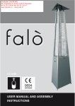
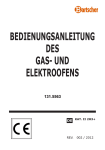
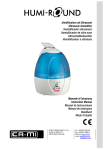
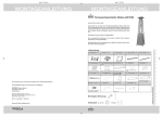
spider remote
I - ISTRUZIONI DI USO E MONTAGGIO
UK - USER MANUAL AND ASSEMBLY INSTRUCTIONS
DE - GEBRAUCHSANLEITUNG UND DIE AUFBAUANLEITUNG
SUNfox INFRA Spider remote
Fig. 1
300
146
100
170
MIN 0,5m
716
MIN 1,5m
MAX 2,5m
MIN 2 m
MIN 2m
MAX 3,5m
Ø 770
MIN 2 m
Rmax = 2,5m
112
B
0
852
A
0
86
825
33
330
Fig. 2
Fig. 3
OK!
2
SUNfox INFRA Spider remote
Fig. 4
OK!
Fig. 5
1
L min 1,5m
L max 2,5m
30∞
1
2
90∞
L = 1,5m
L = 2,5m
3
30∞
SUNfox INFRA Spider remote
Fig. 6
1
2
3
(optional)
4
1,5Volt
torcia
KD
D
AM1
5
22
7
6
1,5Volt
ministilo
K3A
AAA
AM4
8
10
9
12
11
13
14
15
16
17
18
19
20
21
4
SUNfox INFRA Spider remote
LEGENDA: 1) tronchetto di fissaggio, 2) diaframma, 3) raccordo entrata gas, 4) distanziatori, 5)
lamiera copertura superiore, 6) centralina elettronica telecomando, 7) portapile, 8) lamiera copertura inferiore, 9) lamiera laterale SX con asola per centralina, 10) distanziatori, 11) dischi di protezione, 12) lamiera laterale DX, 13) raccordo porta ugello, 14) ugello, 15) gruppo bruciatore, 16)
gruppo pilota, 17) anello protezione bruciatore, 18) scudo bruciatore, 19) parabola riflettente, 20)
anello fissaggio parabola, 21) dadi fissaggio parabola, 22) MINI telecomando.
KEY: 1) retention stub pipe, 2) diaphragm, 3) gas supply connector, 4) spacers, 5) upper cover plate,
6) remote control electronic unit, 7) battery holder, 8) lower cover plate, 9)LH side plate with unit
slot, 10) spacers, 11) protection discs, 12) RH side plate, 13) nozzle holder connector, 14) nozzle,
15) burner unit, 16) pilot unit, 17) burner protection ring, 18) burner shield, 19) reflecting dish, 20)
dish retention ring, 21) dish retention nuts, 22) SMALL remote control.
ZEICHENERKLÄRUNG: 1) Befestigungsstutzen, 2) Blende, 3) Anschlussstück Gaseinlass, 4)
Distanzstücke, 5) Oberes Abdeckblech, 6) Elektronische Steuereinheit Fernbedienung, 7)
Batteriefach, 8) Unteres Abdeckblech, 9) Seitliches Blech LINKS mit Öse für Steuereinheit, 10)
Distanzstücke, 11) Schutzscheiben, 12) Seitliches Blech RECHTS, 13) Düsenanschlussstück, 14) Düse,
15) Brenneraggregat, 16) Leitflammenaggregat, 17) Brennerschutzring, 18) Brennerschild, 19)
Zurückstrahlender Abdeckschirm, 20) Abdeckschirm-Befestigungsring, 21) Muttern der Parabel, 22)
klein Fernbedienung.
5
SUNfox INFRA Spider remote
Diaframma
Blende
Diafragme
Diafragma
Diaphragme
Modello apparecchio
Appliance model
Serie aparato
Modell des Geräts
Modelo aparelho
Modelo aparato
Model
INFRA
Spider
7 kW
GAS G31 - 50 mbar
Diametro diaframma
Diafragme diameter
Diamètre du diaphragme
é Durchmesser Blende
Diâmetro do diafragma
diámetro diafragma
Diameter diafragma
Fig. 7
n∞ di scanalature
number of grooves
nombre de rainures
antal riller
nº de ranuras
número de ranhuras
aantal groeven
mm
1
Ø 1,40
1
IT - ISTRUZIONI PER IL MONTAGGIO DEL DIAFRAMMA GPL (vedi Tab. Fig. 7)
Prima di effettuare la connessione, verificare con la Tab.1 la necessità di montare il diaframma gas (1: Fig.7) sul raccordo entrata dell’innesto (AUSTRIA , GERMANIA e LUSSEMBURGO).
ATTENZIONE! NON MONTARE il diaframma sugli apparecchi alimentati a gas G30/G31 29÷37 mbar.
IMPORTANTE! MONTARE il diaframma solo nel caso in cui sia previsto il funzionamento con pressione di alimentazione a
50 mbar (Austria, Germania, Lussemburgo). Verificare quindi, la tipologia corretta come specificato e illustrato nella Tab..
FR - INSTRUCTIONS POUR LE MONTAGE DU DIAPHRAGME LPG (voir Tab Fig. 7)
Vérifiez, en vous basant sur le Tableau 1, s’il est nécessaire de placer le diaphragme type (fourni) (1: Fig. 7) sur l’ouverture d’arrivée du raccord (uniquement nécessaire en Allemagne et en Autriche).
ATTENTION! NE PAS MONTER de diaphragme sur les appareils à gaz G30/G31 29 : 37 mbar.
IMPORTANT! NE MONTER le diaphragme qu’à condition que l’appareil soit supposé fonctionner à une pression d’alimentation de 50 mbar (Autriche, Allemagne, Luxembourg). Vérifiez donc le type exact mentionné et illustré au Tab..
DE - ANWEISUNGEN FÜR DIE MONTAGE DER MEMBRAN LPG (Se Tab. Abb. 7)
Anhand der Tabelle 1 überprüfen, ehe Sie den Anschluß durchführen, ob die Verwendung der mitgelieferten Gasmembrane
(auf der Zufuhröffnung der “Schnellkupplung”) erforderlich ist (1:Abb. 7) (nur erforderlich für Österreich und Deutschland)
WICHTIG ! KEINE MEMBRANEN auf mit Gas angetriebenen Geräte montieren (G30/G31 29:37mbar).
WICHTIG ! MEMBRAN nur montieren nachdem nachgeprüft wurde, ob das Gerät mit einem Speisungsdruck von 50
mbar funktioniert (Österreich, Deutschland, Luxemburg). Kontrollieren Sie also zuerst den richtigen Typ in der Tabelle.
NL - INSTRUCTIES VOOR DE MONTAGE VAN HET DIAFRAGMA LPG (zie Tab. Fig. 7)
Controleer, voor u de aansluiting tot stand brengt, aan de hand van Tabel 1 of het noodzakelijk is een gasdiafragma (meegeleverd) (1: Fig.7) te plaatsen op de toevoeropening van de “snelkoppeling” (enkel nodig voor OOSTENRIJK en DUITSLAND).
OPGELET! MONTEER GEEN diafragma op de toestellen op gas G30/G31 29 : 37 mbar.
BELANGRIJK! MONTEER het diafragma enkel indien het toestel geacht wordt te functioneren met een voedingsdruk van
50 mbar (Oostenrijk, Duitsland, Luxemburg). Controleer dus het juiste type dat in Tab. wordt vermeld en geïllustreerd.
6
SUNfox INFRA Spider remote
ES - INSTRUCCIONES PARA EL MONTAJE DEL DIAFRAGMA LPG (consulte la Tabla Fig. 7)
Antes de realizar la conexión, controle con ayuda de la Tabla 1 si es necesario instalar el tipo de membrana de gas (viene
con el aparato) (1: Fig.7) en la boca de suministro del acoplamiento (solamente necesario en Austria y Alemania).
¡OJO! NO MONTE NUNCA un diafragma en los aparatos que funcionen con gas G30/G31 29 : 37 mbar.
¡IMPORTANTE! MONTE el diafragma tan solo si se considera que el aparato debería funcionar con una presión de alimentación de 50 mbar (Austria, Alemania, Luxemburgo). Compruebe por lo tanto la versión correcta que viene mencionada e ilustrada en la Tabla.
UK - DIAPHRAGM ASSEMBLY INSTRUCTIONS LPG (see Tab. Fig. 7)
Before you make the connection, check, by means of Table 1, whether it is necessary to install the gas diaphragm (supplied) (1: Fig.7) on the inlet connection of the fit (only necessary in AUSTRIA and GERMANY).
ATTENTION! DO NOT INSTALL a diaphragm on the gas-run appliances G30/G31 29 : 37 mbar.
IMPORTANT! Only INSTALL the diaphragm if the appliance is supposed to function with a supply pressure of 50 mbar
(Austria, Germany, Luxembourg). So, check the correct type mentioned and illustrated in Tab..
PT - INSTRUÇÕES PARA A MONTAGEM DO DIAFRAGMA LPG (veja Tabela Fig. 7)
Controle, antes de fazer a ligação, por meio da Tabela 1, a necessidade da colocação de uma membrana para gás (fornecida) (1: Fig. 7) na abertura de alimentação do acoplamento (só necessário na Áustria e na Alemanha). CAUTELA!
NÃO MONTAR diafragma nos aparelhos a gás G30/G31 29 : 37 mbar.
IMPORTANTE! MONTAR o diafragma só quando o aparelho dever funcionar com uma pressão de alimentação de 50
mbar (Áustria, Alemanha, Luxemburgo). Portanto é necessário verificar o tipo exacto mencionado e ilustrado na Tabela.
NO - MONTERINGSINSTRUKSJON TIL DIAFRAGMA LPG (Se Tab. Fig. 7)
Kontroller (før du gjennomfører tilkoblingen) ved hjelp av Tabell 1 om det er nødvendig å montere gassdiafragmaen
(følger med) (1: Fig. 7) på “hurtigkoplingens” tilførselåpning (kun nødvendig for Østerrike og Tyskland).MERK! IKKE
MONTER diafragmaen på apparater med gass G30/G31 29 : 37 mbar.
VIKTIG! MONTER diafragmaen kun hvis apparatet skal brukes med et tilførselstrykk på 50 mbar (Østerrike,
Tyskland, Luxemburg). Kontroller at det er den rette typen, som anført og illustrert i Tab..
SE - DIAFRAGMANS MONTERINGSINSTRUKTION LPG (se tab. Fig. 7)
Kontrollera innan du ansluter utrustningen med hjälp av tabell 1 om det är nödvändigt att montera gasmembranet
(medföljer) (1: Fig.7) på "snabbkopplingens" tillmatningsöppning (endast nödvändigt i Österrike och Tyskland).
OBS! MONTERA INTE något diafragma på apparaterna för gas G30/G31 29 : 37 mbar.
VIKTIGT! MONTERA diafragmat endast om apparaten är avsedd att användas med ett gastillförseltryck på 50 mbar
(Österrike, Tyskland, Luxemburg). Kontrollera därför att det är den rätta typen, som beskrivs och avbildas i tab..
FI - DIAFRAGMAN ASENNUSOHJE LPG (katso taulukko Kuva 7)
Tarkista, ennen liittämistä, taulukosta 1 onko tarpeen asentaa kaasudiafragma (toimitettu mukana) ”pikaliitoksen”
syöttöaukkoon (1: Kuva 7). (Koskee vain Itävaltaa ja Saksaa.)
HUOM! DIAFRAGMAA EI ASENNETA kaasukäyttöisiin malleihin G30/G31 29 : 37 mbaaria.
TÄRKEÄÄ! ASENNA diafragma vain jos laitetta on tarkoitus käyttää 50 mbaarin syöttöpaineella (Itävalta, Saksa,
Luxemburg). Tarkista siis että kyseessä on oikea taulukossa selostettu ja kuvattu laitetyyppi.
IS - LEI_BEININGAR UM SAMSETNINGU Á HETTU LPG (sjá tab. Fig. 7)
Athugi_ á_ur en tengt er í töflu 1 hvort nau_synleg er a_ festa _ynnuna (fylgir me_) (1: Mynd 7) á mötunarop “hra_tengilsins” (a_eins nau_synlegt í AUSTURRÍKI og __SKALANDI).
ATHUGI_ ! SETJI_ EKKI hettu á gas tæki G30/G31 29 : 37 mbar.
ÁRÍ_ANDI ! SETJI_ A_EINS hettu á tæki sem eru ger_ fyrir _r_sting upp á 450 mbar (Austurríki, __skaland,
Luxemborg) Athugi_ _ví hver ger_in er eins og tala_ er um og s_nt á Tab..
7
SUNfox INFRA Spider remote
Fig. 8
Fig. 9
centralina/control unit
telecomando/remote control
8
C
D
E
F
G
H kW
I kW
L g/h
M Ø mm
AT
-
-
-
-
-
-
-
-
1,65
50
50
AT
-
-
-
-
-
-
-
-
-
-
28-30
37
-
-
-
-
-
-
-
-
-
-
30
30
BE
BG
CH
CY
-
-
-
-
-
-
-
-
-
-
50
30
50
30
CH
CY
CZ
-
-
I3B/P
I3+
I3B/P
I3B/P
I3B/P
I3+
I3B/P
I3B/P
I3B/P
I3+
I3B/P
I3+
I3+
I3+
I3B/P
I3+
I3B/P
I3+
I3B/P
I3P
I3B/P
I3B/P
I3B/P
I3B/P
I3B/P
I3+
I3+
I3B/P
I3+
I3B/P
I3B/P
-
BE
BG
-
-
-
-
-
-
-
-
30
37
-
-
-
-
-
-
-
1,65
50
50
DE
-
-
-
-
-
-
-
-
30
30
-
-
-
-
-
-
-
-
30
30
DK
EE
-
-
-
-
-
-
-
-
28-30
37
ES
-
-
-
-
-
-
-
-
30
30
-
-
-
-
-
-
-
-
28-30
37
FR
-
-
-
-
-
-
-
-
28-30
37
GB
-
-
-
-
-
-
-
-
28-30
37
GR
-
-
-
-
-
30
30
HU
-
A1
-
-
-
28-30
37
IE
-
-
-
-
30
30
IS
-
INFRA Spider remote
-
GB
-
GR
HU
IE
IS
IT
LT
SUN FOX
FI
FR
-
-
LU
-
LV
-
MT
-
NL
-
NO
-
-
-
-
PL
-
-
PT
-
-
RO
SE
-
-
-
-
SK
-
-
SI
-
-
TR
-
-
-
28-30
-
-
-
-
-
IT
LT
-
-
1,65
-
50
LU
-
30
30
LV
-
-
-
30-30
30-30
MT
-
-
-
-
30
30
NL
-
-
-
-
30
30
NO
-
-
-
-
30
30
-
-
-
-
28-30
37
PT
-
-
-
-
-
38-30
37
-
-
-
-
-
-
30
37
RO
SE
-
-
-
-
-
-
28-30
37
SK
-
-
-
-
-
-
30
30
SI
-
-
-
-
-
-
30
30
TR
-
-
-
-
-
-
-
-
-
-
-
-
-
-
-
-
-
-
-
-
-
-
-
-
-
-
-
-
-
-
-
-
-
-
-
-
-
-
-
-
-
-
-
-
CZ
-
-
-
-
-
-
-
-
1,28
ES
-
Q
G30: 545
G31: 536
-
Ø mm O G30 mbar P G31 mbar
4,0 (28-30/37mbar) (Hs)
4,5 (50mbar) (Hs)
-
(Hs)
-
-
7,5
-
0694BQ0922
DE
DK
EE
N
-
-
37
FI
PL
NO, NEEN, NEIN, NON, NE
B
SI, YES, JA, OUI, DA, ANO
- MADE IN ITALY -
ITALKERO Srl - v. Lumumba, 2 - 41100 - Modena - ITALY
A
AT= Osterraich, BE= Belgique, DE= Deutchland, ES= Espana, IT= Italia, DK= Denmark, FI= Finland,
GR= Greece, IS= Iceland, LU= Luxembourg, NL= Holland, NO= Norska, PT= Portugal, SE= Sverige,
CZ=Cesko, EE=Eesti Vab., HU= Magyar Köz, LT=Latui¡as Rep., LV-Lietuvos Resp., PL=Polska Rze.,
MT=Malta, RO=România, SK=Slovensko, SI=Slovenija, TR=Türki¡e, BG=Bulgaria, CY=Cyprus.
SUNfox INFRA Spider remote
0694
cod. 3500010076
LEGENDA colonne: - Columnes esplication
A....Q: sigla paese - land identification - désignation du pays - landesbezeichnung - indicação do país - land van bestemming - määrämaa - bestemmelsesland - bestemmelsesland - pais de destino
B: serie apparecchio - appliance serial- série de l’appareil- serie des geräts - série aparelho - serie aparato - merk - merkki - merke - mærke - marka
C: modello apparecchio - appliance model - serie aparato - modell des geräts -modelo aparelho - modelo aparato - model - mall - model - modelo
D: categoria gas - gas categories - type de gaz - gaskategorie - categoria de gás - categoría de gas - gascategorie - kaasukategoria - gasskategori - gaskategori - categoria de gás
E: tipo apparecchio - appliance type - type d’appareil - typ des geräts - tipo do aparelho - versión aparato - toesteltype - laitetyyppi - type apparat - type apparat - tipo de aparelho
F: matricola apparecchio - appliance code - code appareil - kode geräts - código aparelho - aparato código - serienummer - sarjanumero - serienummer - serienummer - número de série
G: numero codice pin - nip number - numéro de code pin - pin-kodenummer - número de código pin - número de codificación pin - pin code - pin-koodi - pin-kode - pin-kode - código pin
H: portata termica nominale - nominal heat input - débit calorifique nominal - nennbelastung - carga nominal - carga nomina - nominale belasting - nimelliskuormitus - nominell belastning - nominel belastning - carga nominal
I: portata termica ridotta - reduced heat input - débit calorifique minimal - mindestbelastung - carga mínima - carga mínima - minimum belasting - vähimmäiskuormitus - minimumsbelastning - minimumsbelastning - carga mínima
L: consumo orario gas - gas consuction - consommation de gaz - gasverbrauch - consumo de gás - consumo de gas - consumptie - kulutus - forbruk - forbrug - consumo
M: diametro ugello - injector diameter - diamètre du gicleur - durchmesser einspritzdüse - diâmetro do injector - diámetro inyector - diameter inspuiter - ruiskeen läpimitta - diameter innsprøyter - diameter indsprøjter - diâmetro do injector
N: diametro diaframma - diafragme diameter - diamètre du diaphragme -é durchmesser blende - diâmetro do diafragma - diámetro diafragma - diameter diafragma - välikalvon läpimitta - diameter diafragma - diameter diafragma - diâmetro do diafragma
O: press. alim. BUTANO G30 - inlet gas pressure BUTANE G30 - pression de gaz entrante BUTANE G30 - Eintrittsgasdruck Butan G30 - pressão do gás de entrada BUTANO G30 presión gas entrante BUTANO G30 - Gasdruk inlaat Butaan G30 - Butaani G30:n syötön kaasupaine - Gasstrykk inntak butan G30 - Gastryk indtag butan G30 - Pressão de gás à entrada Butano G30
P: press. alim. PROPANO G31 - inlet gas pressure PROPANE G31 - pression de gaz entrante PROPANE G31 - Eintrittsgasdruck Propan G31 - pressão do gás de entrada - PROPANO G31
presión gas entrante PROPANO G31 - Gasdruk inlaat Propaan G31 - Propaani G31:n syötön kaasupaine - Gasstrykk inntak propan G31 - Gastryk indtag propan G31 - Pressão de gás à entrada Propano G31
-
-
20
-
AT
BE
BG
-
-
-
-
-
-
-
-
-
-
20
25
-
-
-
-
-
-
-
-
-
-
20
-
BE
BG
CH
CY
-
-
-
-
-
-
-
-
-
-
20
-
-
CH
CY
CZ
-
-
-
-
-
-
-
-
-
-
20
-
CZ
DE
-
-
-
-
-
-
-
-
-
-
20
20
DE
DK
EE
-
-
-
-
-
-
-
-
-
-
20
-
-
-
-
-
-
-
-
-
-
20
-
DK
EE
ES
-
-
-
-
-
-
-
-
-
20
-
ES
-
-
-
-
-
-
-
-
20
-
-
-
-
-
-
-
-
-
20
25
FR
-
-
-
-
-
-
-
-
20
-
GB
-
-
-
-
-
-
-
-
20
-
GR
-
-
-
-
-
20
-
HU
-
-
-
GB
-
GR
HU
IE
IS
IT
LT
-
-
LU
-
LV
-
MT
-
-
-
-
-
I2H
I2H
I2E
I2H
-
-
-
I2L
I2H
I2E
I2H
I2H
I2H
I2H
I2H
I2H
-
-
NL
-
NO
-
PL
-
-
-
PT
-
-
RO
SE
-
-
-
-
SK
-
-
SI
-
-
TR
-
-
-
-
-
-
-
-
-
-
-
-
-
-
-
-
-
-
-
-
-
-
-
-
Ø mm O G20 mbar P G25 mbar
Q
FI
20
-
IE
-
-
-
-
IS
-
-
20
-
-
-
-
20
-
IT
LT
-
-
-
20
-
LU
-
-
-
7,5
-
SUN FOX
FI
FR
-
-
I2H
I2E
I2H
I2H
I2H
I2H
I2E+
I2H
I2H
I2H
I2H
N
-
-
-
-
-
-
-
-
-
LV
-
-
-
-
-
-
-
MT
-
-
-
-
-
-
-
-
25
NL
-
-
-
-
-
-
-
20
-
NO
-
-
-
-
-
-
-
20
20
-
-
-
-
-
-
-
-
20
-
PT
-
-
-
-
-
-
-
-
20
-
-
-
-
-
-
-
-
-
20
-
RO
SE
-
-
-
-
-
-
-
-
20
-
SK
-
-
-
-
-
-
-
-
20
-
SI
-
-
-
-
-
-
-
-
20
-
TR
-
-
-
-
-
PL
NO, NEEN, NEIN, NON, NE
-
SI, YES, JA, OUI, DA, ANO
-
1,98
I kW
-
G20: 0,714
G25: 0,830
H kW
-
(Hs)
G
-
4,0
F
-
(Hs)
E
I2H
I2E+
I2H
I2H
0694BQ0922
D
-
A1
C
-
INFRA Spider remote
L m3/h M Ø mm
B
AT
A
AT= Osterraich, BE= Belgique, DE= Deutchland, ES= Espana, IT= Italia, DK= Denmark, FI= Finland,
GR= Greece, IS= Iceland, LU= Luxembourg, NL= Holland, NO= Norska, PT= Portugal, SE= Sverige,
CZ=Cesko, EE=Eesti Vab., HU= Magyar Köz, LT=Latui¡as Rep., LV-Lietuvos Resp., PL=Polska Rze.,
MT=Malta, RO=România, SK=Slovensko, SI=Slovenija, TR=Türki¡e, BG=Bulgaria, CY=Cyprus.
Tab.1
- MADE IN ITALY -
ITALKERO Srl - v. Lumumba, 2 - 41100 - Modena - ITALY
0694
cod. 3500010077
LEGENDA colonne: - Columnes esplication
A....Q: sigla paese - land identification - désignation du pays - landesbezeichnung - indicação do país - land van bestemming - määrämaa - bestemmelsesland - bestemmelsesland - pais de destino
B: serie apparecchio - appliance serial- série de l’appareil- serie des geräts - série aparelho - serie aparato - merk - merkki - merke - mærke - marka
C: modello apparecchio - appliance model - serie aparato - modell des geräts -modelo aparelho - modelo aparato - model - mall - model - modelo
D: categoria gas - gas categories - type de gaz - gaskategorie - categoria de gás - categoría de gas - gascategorie - kaasukategoria - gasskategori - gaskategori - categoria de gás
E: tipo apparecchio - appliance type - type d’appareil - typ des geräts - tipo do aparelho - versión aparato - toesteltype - laitetyyppi - type apparat - type apparat - tipo de aparelho
F: matricola apparecchio - appliance code - code appareil - kode geräts - código aparelho - aparato código - serienummer - sarjanumero - serienummer - serienummer - número de série
G: numero codice pin - nip number - numéro de code pin - pin-kodenummer - número de código pin - número de codificación pin - pin code - pin-koodi - pin-kode - pin-kode - código pin
H: portata termica nominale - nominal heat input - débit calorifique nominal - nennbelastung - carga nominal - carga nomina - nominale belasting - nimelliskuormitus - nominell belastning - nominel belastning - carga nominal
I: portata termica ridotta - reduced heat input - débit calorifique minimal - mindestbelastung - carga mínima - carga mínima - minimum belasting - vähimmäiskuormitus - minimumsbelastning - minimumsbelastning - carga mínima
L: consumo orario gas - gas consuction - consommation de gaz - gasverbrauch - consumo de gás - consumo de gas - consumptie - kulutus - forbruk - forbrug - consumo
M: diametro ugello - injector diameter - diamètre du gicleur - durchmesser einspritzdüse - diâmetro do injector - diámetro inyector - diameter inspuiter - ruiskeen läpimitta - diameter innsprøyter - diameter indsprøjter - diâmetro do injector
N: diametro diaframma - diafragme diameter - diamètre du diaphragme -é durchmesser blende - diâmetro do diafragma - diámetro diafragma - diameter diafragma - välikalvon läpimitta - diameter diafragma - diameter diafragma - diâmetro do diafragma
O: press. alim. METANO G20 - inlet gas pressure METHANE G20 - pression de gaz entrante MÉTHANE G20 - Eintrittsgasdruck Erdgas G20 - pressão do gás de entrada METANO G20 presión gas entrante METANO G20 - Gasdruk inlaat METHANE G20 - Metaani G20:n syötön kaasupaine - Gasstrykk inntak Metan G20 - Gastryk indtag Metan G20 - Pressão de gás à entrada Metano G20
P: press. alim. Gas Naturale G25 - inlet gas pressure Natural Gas G25 - pression de gaz entrante Gaz Naturel G25 - Eintrittsgasdruck Erdgas G25 - pressão do gás de entrada - Gas Natural G25
presión gas entrante Gas Natural G25 - Gasdruk inlaat Aardgas G25 - Metaani G25:n syötön kaasupaine - Gasstrykk inntak Erdgas G25 - Gastryk indtag Erdgas G25 - Pressão de gás à entrada Gas Natural G25
Tab.2
9
SUNfox INFRA Spider remote
- IT -
Indice
IL TELECOMANDO
pag. 8
DESCRIZIONE GENERALE
pag. 11
MONTAGGIO
pag. 11
MESSA IN FUNZIONE
pag. 13
SPEGNIMENTO
pag. 17
MANUTENZIONE
pag. 17
RIMESSAGGIO
pag. 18
GARANZIA
pag. 18
EVENTUALI ANOMALIE E RIMEDI
pag. 19
10
SUNfox INFRA Spider remote
CONSERVARE ACCURATAMENTE QUESTO LIBRETTO PER TUTTA LA VITA DELL’APPARECCHIO E
RICHIEDERNE UNO NUOVO IN CASO DI DISTRUZIONE O SMARRIMENTO!
IMPORTANTE! QUALORA LE PARTI RISULTINO DANNEGGIATE NON PROCEDERE ASSOLUTAMENTE CON L’ASSEMBLAGGIO!
IMPORTANTE! NON installare l’apparecchio senza una adeguata copertura che lo protegga dagli agenti
atmosferici.
IMPORTANTE! Questo apparecchio dovrà essere installato in accordo con i Regolamenti, Leggi e Norme
in vigore nel Paese dove sarà utilizzato. L'installazione e l'uso dovranno essere conformi alle istruzioni
indicate dal Costruttore. Consultare le istruzioni prima di installare e di utilizzare l'apparecchio.
IMPORTANTE! TUTTE le operazioni di manutenzione, riparazione o modifica DEVONO essere eseguite da personale professionalmente qualificato e certificato, utilizzando sempre ricambi originali del Costruttore.
IMPORTANTE! Questo apparecchio alimentato a gas è un generatore di calore destinato solamente
all’uso per il quale è stato concepito e certificato (con temperatura ambiente NON inferiore a 0°C
per mod. Telecomandati), ossia come apparecchio per il riscaldamento di ambienti coperti
arieggiati all’esterno. Ogni altro uso è da considerarsi improprio e pertanto pericoloso. Il
Costruttore non può essere considerato responsabile per eventuali danni a persone, animali o
cose, derivati da usi impropri.
IMPORTANTE! E’ VIETATO IL FUNZIONAMENTO IN AMBIENTI CHIUSI: UFFICI, ALL’INTERNO DI
ABITAZIONI, STALLE, ALLEVAMENTI, LUOGHI CON VICINANZA DI VAPORI GAS O PULVISCOLI
POTENZIALMENTE INFIAMMABILI E/O ESPLOSIVI, ECC.
IMPORTANTE! Seguire scrupolosamente TUTTE le istruzioni e le avvertenze elencate in questo
libretto (riguardanti l’INSTALLAZIONE, l’USO e la MANUTENZIONE), il loro mancato rispetto
potrebbe essere causa di malfunzionamenti e/o di pericolo per persone, animali e cose.
IMPORTANTE! QUESTO APPARECCHIO FUNZIONA CON GAS ED HA PARTI CALDE, QUINDI TENERE
L’APPARECCHIO LONTANO DALLA PORTATA DEI BAMBINI.
IMPORTANTE! E’ ASSOLUTAMENTE NECESSARIO RISPETTARE LE DISTANZE DI SICUREZZA DA
OGGETTI O SOSTANZE INFIAMMABILI (Fig.1).
IMPORTANTE! PER IL MONTAGGIO E L’UTILIZZO È NECESSARIO ATTENERSI ALLE NORME ANTINCENDIO E PREVENZIONE INFORTUNI, DEL PAESE DOVE SARÀ UTILIZZATO L’APPARECCHIO.
IMPORTANTE! NON utilizzare l’apparecchio predisposto a GPL, in locali seminterrati o interrati.
IMPORTANTE! L’APPARECCHIO PRODOTTO DAL COSTRUTTORE CON ALIMENTAZIONE A GPL,
NON PUO ESSERE TRASFORMATO PER IL FUNZIONAMENTO A METANO E VICEVERSA.
IMPORTANTE! È assolutamente vietato MODIFICARE l’apparecchio tranne che nei SOLI casi previsti e specificati dal Costruttore.
IMPORTANTE! E’ necessario verificare periodicamente con acqua saponata o mezzi equivalenti,
che NON ci siano perdite di gas dalle tubazioni, dalle connessioni e dall’attacco gas dell’apparecchio. Verificare anche che NON ci siano perdite dalle connessioni, fatte con la bombola o impianto
di distribuzione gas.
IMPORTANTE! il collegamento gas deve essere effettuato con tubazioni rigide e bene ancorate.
IMPORTANTE! Prima di procedere con le operazioni di montaggio, verificare che tutte le parti componenti l’apparecchio siano predisposte per il tipo di gas e pressione previsti per l’utilizzo nel
rispetto delle Normative vigenti nel Paese di utilizzo.
11
SUNfox INFRA Spider remote
DESCRIZIONE GENERALE
Per il suo particolare tipo di funzionamento ad irraggiamento diretto e riflesso, quest’apparecchio
permette di riscaldare una superficie di circa 20/25 m2 (Fig.1), naturalmente in ambienti con un
buon flusso di aria fresca come ad esempio: terrazze, pergolati, ristoranti, bar, birrerie e installazioni all’aperto (giardini, marciapiedi, ecc).
IMPORTANTE! in tutte le condizioni di installazione deve essere presente una adeguata copertura
che protegga l’apparecchio dagli agenti atmosferici.
L’apparecchio ha un utilizzo molto semplice, costruito secondo le norme di sicurezza CE, è stato
testato, omologato ed é sorvegliato dall’Ente Omologatore Notificato al quale il Costruttore ha affidato da sempre la maggior parte delle proprie certificazioni nel settore gas.
Tipologie di installazione:
- FISSA AL MURO, tramite una mensola ad angolo (accessorio);
- FISSA AL SOFFITTO, tramite una piastra di fissaggio (accessorio);.
IMPORTANTE! questi due tipi di installazione devono essere eseguite soltanto da personale professionalmente qualificato), utilizzando gas Propano/Butano (bombolone o gas di rete) o gas naturale
di rete.
IMPORTANTE! questo apparecchio può essere installato SOLTANTO SOTTO COPERTURE fisse o
mobili, per proteggerlo da pioggia e infiltrazioni d’acqua che lo danneggerebbero in maniera
seria e pericolosa. Il Costruttore non può essere considerato responsabile per eventuali danni a
persone, animali o cose, derivati da usi impropri ed infiltrazioni d’acqua scaturite dalla mancata
o adeguata copertura dell’apparecchio.
MONTAGGIO
Estrarre dagli imballi tutte la parti che compongono l’apparecchio, facendo particolare attenzione
al gruppo bruciatore (Fig.6: 15).
Verificare prima l’integrità e conformità del contenuto degli imballi questi ultimi devono essere successivamente smaltiti secondo le normative vigenti.
Verifica del contenuto IMBALLI:
A: Fig.2 = gruppo bruciatore, sacchetto con 1 diaframma per GPL con chiave a brugola + foglio di
istruzioni.
B: Fig.2 = parabola di copertura e viti di fissaggio.
IMPORTANTE! QUALORA LE PARTI RISULTINO DANNEGGIATE NON PROCEDERE ASSOLUTAMENTE CON L’ASSEMBLAGGIO!
- FASI DI MONTAGGIO “SPIDER” (tipologia FISSA a parete o soffitto con bombolone GPL o GAS di rete):
IMPORTANTE! Prima di procedere con l’installazione, verificare che sotto la flangia di fissaggio,
NON siano presenti sottotraccia, cavi elettrici, tubazioni acqua o gas.
IMPORTANTE! Prima di procedere con le operazioni di montaggio, verificare che le parti componenti l’apparecchio siano predisposte per il tipo di gas e la pressione previsti dall’utilizzo e dalle
norme vigenti.
12
SUNfox INFRA Spider remote
Qualora si prevede di utilizzare l’apparecchio con gas di petrolio liquefatti GPL, montare come illustrato in Fig. 7, il diaframma conforme al modello di apparecchio, come specificato nelle istruzioni
accluse nella confezione”kit diaframmi”, nella targa dati dell’apparecchio e nelle tabelle.
1 – Poggiare sul muro o al soffitto la flangia e segnare la posizione dei fori per il fissaggio (Fig.5);
forare e inserire i tasselli.
2 – Fissare la flangia utilizzando i tasselli.
NOTA: verificare che i tasselli, in dotazione, per il fissaggio dell’apparecchio siano idonei a
sostenerne il peso tenendo conto del materiale con cui é costruito il soffitto o la parete, altrimenti
sostituirli con altri più idonei.
3 – Montare e fissare se previsto, i tubi di prolunga della mensola o del supporto, dopo averli eventualmente adattati alla lunghezza necessaria, utilizzando le viti adatte (Fig.5).
4 – Inserire la parabola (Fog.6: 19) di copertura sul gruppo bruciatore e bloccarla subito con le viti
in dotazione (Fog.6: 21).
5 – Se l’apparecchio è previsto per funzionare a gas GPL con alimentazione a 50 mbar montare il
diaframma a corredo (Fig.7: 1) del valore indicato in tabella.
6 – Collegare il raccordo di entrata con il tubo di alimentazione gas, la parte terminale superiore filettata (1/4” gas destrorso) consente: di raccordarsi direttamente con una tubazione metallica rigida.
7 – Verificare che il tipo di erogazione e/o la pressione di alimentazione gas corrispondano a
quelli di targa (vedi Tabelle), montare qualora necessario, il riduttore/regolatore di pressione (NON
a corredo).
8 - Acquistare a parte, il raccordo ed il tubo di collegamento, del tipo e materiale adatti alle normative del paese dove avviene l’installazione.
9 - A seconda della lunghezza di installazione, bloccare l’apparecchio con cavi di sicurezza
(Fig.5).
IMPORTANTE! L’ambiente nel quale il generatore di calore verrà utilizzato deve avere un volume
di almeno 20 m3 per ogni kW di potenza calorica nominale e deve essere ben arieggiato, quindi
per utilizzare un INFRA SPIDER si dovrà disporre di un volume di circa 150 m3.
IMPORTANTE! Non scoprire o non appoggiare MAI a terra l’estremità aperta del raccordo gas
del gruppo bruciatore, prima di avere effettuato i collegamenti, lasciarlo adeguatamente protetto
con l’apposito tappo, evitando così l’entrata di corpi estranei che possono diventare causa di
possibili danneggiamenti delle tenute gas od eventuali ostruzioni del condotto gas.
IMPORTANTE! È assolutamente vietato MODIFICARE l’apparecchio tranne che nei soli casi previsti
dal Costruttore.
- Montare le batterie per l’accensione elettronica del Pilota:
1 - per facilitare l’accesso al vano portabatterie, svitare ed abbassare la parabola di copertura
(Fig.6: 19) del gruppo bruciatore (Fig.6: 15).
2 - localizzato il vano porta batterie (Fig.6: 7), aprire il coperchio ed inserire le batterie rispettando
la giusta polarità.
3 - rimontare tutto correttamente con procedimento inverso.
13
SUNfox INFRA Spider remote
MESSA IN FUNZIONE
IMPORTANTE! TOGLIERE TUTTE LE PELLICOLE DI PROTEZIONE, SE PRESENTI.
IMPORTANTE! Per evitare eventuali sfiammate dovute all’accumulo di gas, lasciare passare circa 1
o 2 minuti prima di ripetere la procedura di riaccensione.
IMPORTANTE! NON mettere mai in funzione l’apparecchio senza prima avere montato la parabola
di copertura e completato l’intero assemblaggio. Il gruppo bruciatore NON deve mai essere coperto
o parzialmente coperto.
IMPORTANTE! NON coprire l’apparecchio se spento da poco, aspettare che si raffreddi.
IMPORTANTE! Proteggere l’apparecchio da urti, forte umidità o pioggia.
IMPORTANTE! Rispettare sempre le distanze minime di installazione e fare attenzione che materiali
infiammabili non vengano mai a diretto contatto con l’apparecchio.
IMPORTANTE! SOLO PER LA 1° ACCENSIONE, DA EFFETTUARSI ALL’APERTO O IN AMBIENTE BENE
ARIEGGIATO, L’APPARECCHIO POTREBBE EMANARE DEI VAPORI E ODORI PER UN BREVE PERIODO.
- Accensione
Sequenza regolazione, premendo il pulsante sul telecomando o direttamente sulla centralina: ON,
MAX, MEDIA, MIN e OFF.
1 - CENTRALINA: tenere premuto il pulsante di ON/OFF per circa 4” sino a che non avviene
l’accensione, una volta acceso ad ogni pressione del pulsante ON/OFF l’apparecchio passa da
fiamma MAX a MEDIA a MIN ed infine OFF.
IMPORTANTE! Nel caso in cui si desidera utilizzare il pulsante di ON/OFF posto sulla centralina a
bordo apparecchio, si raccomanda di prestare particolare attenzione a non entrare in contatto diretto
con la fiamma o parti calde per evitare scottature o ustioni serie.
1b - TELECOMANDO: premere il pulsante di ON/OFF per accendere l’apparecchio. Una volta
acceso si può scegliere la fiamma/potenza desiderata (MAX, MEDIA e MIN) utilizzando i due tasti
+ e - sul Telecomando.
IMPORTANTE! Questo ritardo nell’accensione non é un “difetto” della centarlina elettronica ma é
stata appositamente studiato dal Costruttore per garantire la sicurezza dell’apparecchio ed evitare
accensioni accidentali.
IMPORTANTE! Se la fiamma del pilota dovesse spegnersi per cause accidentali o mancanza di gas,
la fuoriuscita di gas sarà automaticamente interrotta tramite il dispositivo di sicurezza installato.
IMPORTANTE! Evitare molteplici tentativi di accensione: se l’apparecchio non dovesse funzionare
subito, controllare che TUTTE le operazioni di installazione siano state eseguite correttamente.
IMPORTANTE! Durante il funzionamento, la regolazione ed anche dopo lo spegnimento, NON TOCCARE l’unità bruciatore e la parabola di copertura in quanto la loro elevata temperatura potrebbe provocare ustioni.
La regolazione della potenza può essere effettuata anche durante il funzionamento dell’apparecchio
tramite il telecomando o con il pulsante posto sulla centralina.
IMPORTANTE! Per il funzionamento dell’apparecchio a GPL all’aperto e per temperature inferiori a 2°C
è consigliato l’impiego di gas Propano.
14
SUNfox INFRA Spider remote
SPEGNIMENTO
1 - Premere il pulsante ON/OFF sul telecomando (Fig.8: 1) o sulla centralina a bordo apparecchio.
2 - Chiudere il rubinetto dell’alimentazione gas.
IMPORTANTE! SE L’APPARECCHIO NON VIENE UTILIZZATO PER UN LUNGO PERIODO DI TEMPO,
RIMUOVERE LE BATTERIE DELLA CENTRALINA DI ACCENSIONE (Fig.6: 7) E DEL TELECOMANDO
(Fig.6: 22) DAL SUO ALLOGGIAMENTO, PER EVITARE FUORIUSCITE DI LIQUIDO CORROSIVO CHE
POTREBBERO CAUSARE DANNI.
MANUTENZIONE
IMPORTANTE! PRIMA DI EFFETTUARE QUALSIASI TIPO DI MANUTENZIONE, ASSICURARSI CHE IL
RUBINETTO DELL’ALIMENTAZIONE GAS SIA CHIUSO.
La manutenzione riguarda:
- Pulizia esterna dell’apparecchio (utilizzare un panno morbido e prodotti per la pulizia a base
neutra, evitando di versarli direttamente sulle parti da pulire).
- Verifica dell’integrità e pulizia di tutte le parti che compongono l’apparecchio, in caso di usura o
rottura sostituire solo con ricambi originali del Costruttore.
- Sostituzione batterie per l’accensione elettronica (Fig.6: 7) della centralina Telecomando (Fig.6: 6).
SOSTITUZIONE UGELLO
IMPORTANTE! L’apparecchio NON deve essere, in nessun modo, trasformato da Metano a GPL o
viceversa, qualsiasi tentativo di trasformazione é da considerarsi pericoloso ed il Costruttore non
può essere considerato responsabile di eventuali danni a persone o cose derivanti da questa o altre
manomissioni. L’apparecchio perciò deve essere assemblato SOLO dal Costruttore ed ordinato
dall’utente direttamente per il tipo di gas che verrà utilizzato per il funzionamento.
RIMESSAGGIO
Qualora si preveda un lungo periodo di inattività dell’apparecchio (cambio di stagione o per altre
cause), seguire le seguenti indicazioni:
- Coprire SEMPRE il gruppo bruciatore e la base per evitare ostruzioni (ragnatele, polvere) o danneggiamenti (ammaccature, agenti atmosferici, ecc.).
IMPORTANTE! Non riporre MAI, assieme all’apparecchio, una o più bombole di gas che devono
invece SEMPRE RIMANERE IN AMBIENTI ESTERNI ed in maniera conforme alle Leggi e Normative
vigenti del Paese di utilizzo.
15
SUNfox INFRA Spider remote
GARANZIA
Il vostro Apparecchio gode di una garanzia di DUE ANNI a partire dalla data di acquisto.
La garanzia copre tutti i difetti di fabbricazione con esclusione di difetti dovuti a usi diversi da quelli
specificati e previsti dal Costruttore per questo apparecchio.
La ricevuta dell’acquisto o lo scontrino di cassa rappresentano l’inizio del periodo di copertura del
certificato della garanzia.
Questo apparecchio non è adatto ad impieghi professionali.
L’usura, la corrosione, l’eventuale deformazione, la decolorazione o imbrunimento (in particolare
dell’alluminio, delle parti satinate o del tubo in vetro) dovute al contatto con la fiamma e all’irraggiamento continuo, sono da ritenersi normali ed in nessun caso possono essere considerati difetti di
fabbricazione, sono causa delle normali condizioni di utilizzo.
Inoltre è normale che, dopo un uso prolungato, sia necessario sostituire alcune parti usurate ma utilizzando SEMPRE ricambi originali del Costruttore, facendo eseguire la manutenzione/riparazione da personale professionalmente Qualificato e Autorizzato dal Costruttore.
16
EVENTUALI ANOMALIE E RIMEDI
ANOMALIA
CAUSA
RIMEDIO
1-Flusso alimentazione gas insufficiente (cattiva
gasificazione GPL o sporcizia nell’impianto)
o regolatore di pressione starato o guasto.
2-Flusso alimentazione gas assente (bombola
esaurita o interruzione fornitura gas) oppure
regolatore di pressione guasto.
3-Improvvisa raffica di vento (superiore a 3
m/s) con i pannelli copri bombola rimossi.
4-Sporcizia nel circuito gas.
5-Perdite di gas.
1-Pulire, tarare / sostituire.
1-Presa di corrente CA allentata o fusibile
cortocircuitato.
2-Carica batteria troppo bassa, pacco batterie
(B1) difettoso o poli allentati.
3-Ricevitore infrarossi (D) coperto.
4-Pulsante POWER del telecomando non è
stato premuto per 2 secondi.
5-Telecomando difettoso o batterie scariche.
6-Cavi collegamento tra scheda comando
anteriore e posteriore sono lenti o difettosi.
7-Schede di comando difettose.
1-Riparare / sostituire.
1-Distanza tra il dispositivo di accensione
(HV1) e la messa a massa oppure la distanza
tra gli elettrodi (HD) è eccessiva.
2-La parte in ceramica del dispositivo di
accensione (HV1) è rotta o difettosa.
3-Cavo alta tensione allentato, rotto o
cortocircuitato.
4-Nel set pilota manca la messa a massa.
5-Scheda di comando posteriore difettosa.
1-Regolare la distanza a 4 ± 0,5 mm.
(La resistenza del cavo deve essere collegata
vicino al dispositivo d’accensione).
2-Sostituire la parte in ceramica.
Scintilla presente ma la fiamma pilota non si
accende.
1-Manca alimentazione gas.
2-Collegamento difettoso tra scheda comando
anteriore e posteriore o cavi di collegamento
allentati.
3-Iniettore pilota bloccato.
4-Scheda comando posteriore difettosa.
5-Valvole G1 e G2 difettose.
1-Controllare.
2-Riposizionare o sostituire cavi.
3-Controllare o sostituire.
Diametro ugello: GPL: 0,35 mm; METANO:
0,55 mm.
4-Sostituire.
5-Sostituire.
Pilota acceso, scintille di continuo che non si
arrestano (nessun rilevamento di fiamma).
1-Cavi sensore fiamma (S) e dispositivo di
accensione (HV) invertiti o allentati.
2-Sensore fiamma (S1) e massa sono in
cortocircuito.
3-Sensore fiamma (S1) non rileva la fiamma.
4-Fiamma pilota viene bruciata all’interno del
tubo pilota.
5-Scheda comando posteriore difettosa.
1-Sistemare.
1-Cavi difettosi o i terminali allentati.
2-Ugello bruciatore principale bloccato.
1-Riparare o sostituire.
2-Controllare se la pressione del gas è
presente, sostituire il set pilota o perforare
nuovamente l’iniettore.
3-Controllare se la pressione del gas è assente,
sostituire le valvole “M” e “L”.
4-Sostituire.
5-Sostituire.
Mancanza di fiamma
All’accensione l’apparecchio non funziona,
l’indicatore POWER non si accende.
Nessuna scintilla all’accensione
dell’apparecchio.
Pilota acceso, il bruciatore principale non si
accende.
3-Valvole “M” e “L” difettose.
4-Schede comando anteriore e posteriore
difettose.
5-Telecomando difettoso.
La fiamma bassa si accende; la fiamma media
non si accende.
2-Controllare / sostituire.
3-Ripristinare coperture.
4-Controllare / pulire.
5-Controllare / riparare.
2-Sostituire batterie, serrare i poli.
3-Realizzare foro per ricevitore.
4-Premere POWER per 2 secondi, rilasciare
e premere di nuovo.
5-Sostituire Telecomando o Batterie.
6-Sistemare o sostituire.
7-Sostituire.
3-Riparare o sostituire.
4-Collegare a massa.
5-Sostituire.
2-Ripristinare la posizione corretta.
3-Ripristinare la posizione corretta.
4-Sostituire.
5-Sostituire.
1-Cavi difettosi o terminali allentati.
2-Valvola “M” difettosa o ugello valvola “M”
bloccato.
3-Scheda comando anteriore difettosa.
4-Telecomando difettoso.
1-Riparare o sostituire.
2-Sostituire.
1-Cavi difettosi o terminali allentati.
2-Valvola “L” difettosa o l’ugello valvola “L”
bloccato.
3-Scheda comando anteriore difettosa.
4-Telecomando difettoso.
1-Riparare o sostituire.
2-Sostituire.
Durante i cicli d’accensione, l’apparecchio
non si spegne in 25 secondi.
1-Scheda comando anteriore difettosa.
1-Sostituire.
La batteria del telecomando è scarica.
1-La batteria si sta scaricando.
1-Sostituire.
La fiamma media si accende; la fiamma bassa
non si accende.
17
3-Sostituire.
4-Sostituire.
3-Sostituire.
4-Sostituire.
SUNfox INFRA Spider remote
- GB -
Contents
THE REMOTE CONTROL
page 8
GENERAL DESCRIPTION
page 22
ASSEMBLY
page 22
START-UP
page 24
SWITCH-OFF
page 28
MAINTENANCE
page 28
STORAGE
page 29
WARRANTY
page 29
TROUBLESHOOTING
page 30
18
SUNfox INFRA Spider remote
CAREFULLY LOOK AFTER THIS BOOKLET FOR THE ENTIRE LIFE OF THE APPLIANCE AND REQUEST
A NEW ONE IN CASE OF DAMAGE OR LOSS!
IMPORTANT! SHOULD THE PARTS BE DAMAGED, DO NOT GO AHEAD WITH ASSEMBLY!
IMPORTANT! DO NOT install the appliance without adequate covering to protect it against the
weather.
IMPORTANT! This appliance must be installed in compliance with the Regulations, Laws and
Standards applicable in the Country of use. Installation and use must be in conformity with the
instructions provided by the Manufacturer. Refer to the instructions before installing and using the
appliance.
IMPORTANT! ALL the maintenance, repair or modification operations MUST be performed by professionally qualified and certified personnel and always using the Manufacturer’s original spare parts.
IMPORTANT! This gas-fuelled appliance is a heat generator intended only for the use for which it
was designed and certified (with room temperature NOT below 0°C for Remote-controlled
models), or as an appliance for heating open, ventilated or outdoor environments. All other uses
are to be deemed improper and therefore hazardous. The Manufacturer disclaims all liability for
any injury to persons or animals or damage to things caused by improper use.
IMPORTANT! OPERATION IN CLOSED ENVIRONMENTS SUCH AS OFFICES, INSIDE HOMES, STABLES, ANIMAL FARMS, PLACES NEAR GAS VAPOURS OR POTENTIALLY INFLAMMABLE DUSTS
AND/OR EXPLOSIVES, ETC. IS FORBIDDEN.
IMPORTANT! Carefully follow ALL the instructions and precautions indicated in this booklet (concerning INSTALLATION, USE and MAINTENANCE). Failure to abide by these instructions could
cause malfunctions and/or endanger people, animal and things.
IMPORTANT! THIS APPLIANCE IS GAS FUELLED AND PARTS OF IT BECOME HEATED. CONSEQUENTLY, KEEP IT OUT OF REACH OF CHILDREN.
IMPORTANT! ALWAYS COMPLY WITH SAFETY DISTANCES FROM OBJECTS OR INFLAMMABLE SUBSTANCES (Fig. 1).
IMPORTANT! TO ASSEMBLE AND USE, ABIDE BY THE FIRE-FIGHTING AND ACCIDENT-PREVENTION REGULATIONS OF THE COUNTRY WHERE THE APPLIANCE IS USED.
IMPORTANT! DO NOT use the appliance set for LPG in basements or cellars.
IMPORTANT! The appliance designed to use LPG CANNOT be modified to use natural gas and
vice versa.
IMPORTANT! MODIFYING the appliance is absolutely forbidden except ONLY in those cases indicated and authorised by the Manufacturer.
IMPORTANT! Periodically check for gas leaks in pipes, connections and the gas/appliance connection using soapy water. Make sure there are NO leaks from the connections to tanks or gas distribution system.
IMPORTANT! the gas connection must be made using rigid and well anchored pipes.
IMPORTANT! Before proceeding with assembly operations, make sure all the parts making up the
appliance are suitable for the type of gas and pressures according to the Regulations applicable in
the Country of use.
19
SUNfox INFRA Spider remote
GENERAL DESCRIPTION
Due to its specific type of operation with direct and reflected radiation, this appliance permits heating a surface of around 20/25 m2 (Fig. 1), naturally in environments with good fresh air ventilation, for example: terraces, pergolas, restaurants, cafés and open-air installations (gardens, pavements, etc).
IMPORTANT! In all installation conditions, adequate covering must be provided to protect the
appliance against the weather.
The appliance is very simple to use and built according to CE safety standards. It has been tested,
approved and is controlled by the Notified Approval Institute to which the Manufacturer has always
entrusted most of its certifications in the gas industry.
Types of installation:
- WALL-MOUNTED, by means of a corner bracket (accessory);
- FASTENED TO CEILING, by means of a retention plate (accessory);
IMPORTANT! These two types of installation must only be made by professionally qualified personnel, using Propane/Butane gas (cylinder or mains gas) or mains natural gas.
IMPORTANT! This appliance can ONLY BE INSTALLED UNDER FIXED OR MOBILE COVERINGS, to
protect it against rain and water infiltrations which could seriously damage it and represent a
hazard. The Manufacturer disclaims all liability for any injury to persons or animals and damage
to things caused by improper use and the infiltration of water resulting from failure to place the
appliance under a covering.
ASSEMBLY
Take all the parts making up the appliance out of the packaging, with special care given to the burner unit (Fig. 6: 15).
First, check the integrity and the conformity of the contents of the packaging (the latter must be
disposed of according to applicable regulations).
Check the contents of the PACKAGING
A – Fig. 2 = burner unit, bag with 1 diaphragm for LPG, with Allen wrench + instruction leaflet
B: Fig. 2 = Cover dish and retention screws.
IMPORTANT! IN CASE OF DAMAGE TO THE PARTS DO NOT GO AHEAD WITH ASSEMBLY!
“SPIDER” ASSEMBLY OPERATIONS (FIXED wall or ceiling mounted with LPG cylinder or mains gas):
IMPORTANT! Before starting installation, make sure that underneath the retention flange, there
are NO chases, power wires, water or gas pipes.
IMPORTANT! Before starting assembly, make sure the parts making up the appliance are set for
the type of gas and the operating pressure indicated by applicable regulations.
20
SUNfox INFRA Spider remote
If the appliance is to be used with LPG liquefied petroleum gases, fit the diaphragm in conformity
with the appliance model as shown in Fig. 7, according to the instructions in the “diaphragm kit”, on
the appliance data plate and on the tables.
1 – Rest the flange on the wall or ceiling and mark the position of the fastening holes (Fig. 5);
drill and fit the anchors.
2 – Fasten the flange using the anchors
NOTE: make sure the fastening anchors provided are suitable for withstanding the weight, taking into
account the material used to make the ceiling or wall, otherwise replace with more suitable ones.
3 – If envisaged, fit and fasten the extension pipes of the bracket or support, after having adapted
these to the required length, using suitable screws (Fig. 5)
4 – Fit the cover dish (Fig. 6: 19) on the burner unit and secure immediately with the screws provided (Fig. 6: 21)
5 – If the appliance is set to operate with LPG gas, with supply pressure 50 mbar, fit the diaphragm
provided (Fig. 7: 1) of the value indicated on the table.
6 – Connect the inlet connector to the gas supply pipe. The threaded top end part (1/4” gas righthand screw) permits directly connecting up to a rigid metal pipe.
7 – Make sure the type of gas supply and/or pressure correspond to that shown on the plate (see
Tables). If necessary, fit a pressure reducer/regulator (NOT provided).
8 – Purchase the connection union and pipe separately. These must be of a type and material suitable for the regulations of the country where installation is made.
9 – Depending on the length of the installation, secure the appliance with safety cables (Fig. 5)
IMPORTANT! The environment in which the heat generator is used must have a volume of at least
20 m3 for each kW of nominal heat output and it must be well ventilated. To use an INFRA SPIDER, a volume of around 150 m3 will be required.
IMPORTANT! NEVER uncover or rest the open part of the burner unit gas connection on the
ground. Before making connections, make sure this is adequately protected by means of the cap
provided, thus preventing entry of foreign bodies that could potentially cause damage to the gas
seals or obstruct the gas pipe.
IMPORTANT! MODIFYING the appliance is absolutely forbidden, except in the cases indicated by
the Manufacturer.
Fitting the batteries (for electronic Pilot ignition):
1 – for easier access to the battery compartment, loosen and lower the cover dish (Fig. 6: 19) of the
burner unit (Fig. 6: 15);
2 – after locating the battery compartment (Fig. 6: 7), open the cover and fit the batteries respecting
the right polarity.
3 – fit everything back correctly in the opposite sequence.
21
SUNfox INFRA Spider remote
START-UP
IMPORTANT! Remove all the protective films if fitted.
IMPORTANT! To prevent any blaze-ups due to gas accumulation, allow 1 or 2 minutes to pass before
repeating the ignition procedure.
IMPORTANT! NEVER start the appliance without first fitting the cover dish and fully completing
assembly. The burner unit must NEVER be covered or partially covered.
IMPORTANT! DO NOT cover the appliance if this has only just been switched off. Wait for it to cool down.
IMPORTANT! Protect the appliance against knocks, strong humidity or rain.
IMPORTANT! Always respect minimum installation distances and be careful that inflammable materials never come into direct contact with the appliance.
IMPORTANT! WHEN FIRST STARTED – IN THE OPEN AIR OR WELL-VENTILATED ENVIRONMENT –
THE APPLIANCE COULD GIVE OFF VAPOURS OR SMELLS FOR A SHORT TIME.
- Ignition
Regulation sequence, by pressing the button on the remote control or directly on the control unit:
ON, MAX, MEDIUM, MIN and OFF
1 – CONTROL UNIT: keep the ON/OFF button pressed for about 4” until ignition occurs. Once on, every time
the ON/OFF button is pressed, the appliance switches from MAX flame to MEDIUM to MIN and finally to OFF.
IMPORTANT! In case of having to use the ON/OFF button on the control unit on board the appliance, always be careful never to come into direct contact with the flame or hot parts to avoid burns.
1b – REMOTE CONTROL: press the ON/OFF button to start the appliance. Once ignited, the required
flame/output can be chosen (MAX, MEDIUM and MIN) using the two keys + and – on the Remote Control.
IMPORTANT! This delay in ignition is not a “fault” of the electronic control unit but has been specially
designed by the Manufacturer to ensure the safety of the appliance and prevent accidental starting.
IMPORTANT! If the pilot flame goes out, accidentally or due to lack of gas, the gas supply will be
automatically interrupted by means of the installed safety device.
IMPORTANT! Avoid repeated ignition attempts: if the appliance does not operate immediately,
make sure ALL the installation operations have been performed correctly.
IMPORTANT! During operation and also after switch off, DO NOT TOUCH the burner unit or the
cover dish. These are hot and could cause burns.
Power adjustment can also be made during appliance operation by means of the remote control or
using the button on the control unit.
IMPORTANT! If the appliance is fuelled by LPG in the open air and with temperatures below 2°C the
use of Propane gas is recommended.
SWITCHING OFF
1 – Press the ON/OFF button on the Remote Control or on the control unit on board the appliance.
2 – Close the gas supply tap.
IMPORTANT! IF THE APPLIANCE IS NOT USED FOR A LONG PERIOD, REMOVE THE IGNITION
UNIT BATTERIES (Fig. 6: 7) AND THOSE OF THE CONTROL UNIT (Fig. 6: 22) FROM THEIR HOUSING, TO PREVENT CORROSIVE LIQUID LEAKING OUT AND CAUSING DAMAGE.
22
SUNfox INFRA Spider remote
MAINTENANCE
IMPORTANT! Before performing any type of maintenance, make sure the gas supply tap is closed.
Maintenance concerns:
- Cleaning the outside of the appliance (use a soft cloth and neutral cleaning products and avoid
pouring these directly on the part to be cleaned).
- Checking the integrity of all the parts making up the appliance; in case of wear or breakage, only
replace with the Manufacturer’s original spare parts.
- Replacing batteries for electronic ignition (Fig. 6: 7) of the Remote Control unit (Fig. 6: 6).
NOZZLE REPLACEMENT
IMPORTANT! The appliance must NEVER for any reason be transformed from Natural gas to LPG or vice
versa. Any attempt to make this change is to be deemed hazardous and the Manufacturer disclaims any
liability for any ensuing injury to people or damage to things. The appliance must ONLY be assembled
by the Manufacturer and ordered by the user directly for the type of gas to be used for operation.
STORAGE
If the appliance is not used for a long time (change of season or other reasons), follow the instructions below:
- ALWAYS cover the burner unit and base to avoid obstructions (cobwebs, dust) or damage (denting,
weather conditions, etc.).
IMPORTANT! NEVER store the appliance together with one or more gas cylinders. These must always be
kept in outside premises and in conformity with the Law and Regulations applicable in the Country of use.
WARRANTY
Your appliance is covered by a two-year warranty starting on the day of purchase.
The warranty covers all manufacturing faults except those caused by use of the appliance in a way
different to that specified and intended by the Manufacturer.
The warranty starts on the date indicated on the purchase and cash receipt.
This appliance is not intended for professional uses.
Wear, corrosion, any deformation, decolouring or burnishing (especially of aluminium, satin-finish
parts or the glass pipe) due to contact with the flame and continuous heat radiation are to be considered normal and under no circumstances can be considered manufacturing defects. These are caused by normal wear and tear.
It is also normal, after prolonged use, for worn parts to be replaced ALWAYS using the
Manufacturer’s original spare parts and having maintenance/repairs done by professionally-qualified personnel authorised by the Manufacturer.
23
SUNfox INFRA Spider remote
TROUBLESHOOTING
FAULT
No flame
When ignited the appliance does not work,
The POWER indicator does not come on.
No spark when the appliance is started.
Spark ok but pilot flame does not come on.
CAUSE
REMEDY
1-Not enough gas supply (bad LPG gasification
or dirt in system)
or pressure regulator not set properly or faulty.
2-No gas flow (tank empty or interruption in
supply) or pressure regulator faulty.
3-Sudden gust of wind (above 3 m/s) with
gas tank panels removed.
4-Dirt in gas circuit.
5-Gas leaks.
1-Clean, set / replace.
1-AC power point loose or short-circuited
fuse.
2-Battery charge too low, battery pack faulty
(B1) or poles loose.
3-Infra-red receiver (D) covered.
4-The POWER button of the remote control
has not been pressed for 2 seconds.
5-Remote control faulty or batteries low.
6-Connection cables between front and rear
control boards loose or faulty.
7-Control boards faulty.
1-Repair / replace.
1-Distance between the ignition device
(HV1) and the earth connection or the distance
between the electrodes (HD) is excessive.
2-The ceramic part of the ignition device (HV1)
is broken or faulty.
3-High-voltage cable loose, broken or shortcircuited.
4-No earth connection in pilot set.
5-Rear control board faulty.
1-Regulate the distance to 4 __0.5 mm.
(The cable resistance must be connected close
to the ignition device).
2-Replace the ceramic part.
1-No gas supply.
2-Connection faulty between front and rear
connection boards or power cables loose.
3-Pilot injector blocked.
1-Check.
2-Reposition or replace cables.
3-Check or replace.
Nozzle diameter: LPG: 0.35 mm; NATURAL
GAS: 0.55 mm.
4-Replace.
5-Replace.
4-Rear control board faulty.
5-Valves G1 and G2 faulty.
2-Check / replace.
3-Replace panels.
4-Check / clean.
5-Check / repair.
2-Replace batteries, tighten poles
3-Make hole for receiver.
4-Press POWER for 2 seconds, release and
press again.
5-Replace Remote Control or Batteries
6-Remedy or replace.
7-Replace.
3-Repair or replace.
4-Make earth connection.
5-Replace.
Pilot flame on, sparks continue without stop
(no flame detection).
1-Flame sensor cables (S) and ignition device
(HV) switched over or loose.
2-Flame sensor (S1) and earth short circuited.
3-Flame sensor (S1) fails to detect flame.
4-Pilot flame burns inside pilot pipe.
5-Rear control board faulty.
1-Put right.
Pilot flame on, the main burner does not come
on.
1-Cables faulty or terminals loosened.
2-Main burner nozzle blocked.
1-Repair or replace.
2-Check gas pressure, replace pilot set or
perforate injector again.
3-Check gas pressure, replace “M” and “L”
valves.
4-Replace.
5-Replace.
3-“M” and “L” valves faulty.
4-Front and rear control boards faulty.
5-Faulty remote control.
The low flame comes on; the medium flame
does not.
2-Restore correct position.
3-Restore correct position.
4-Replace.
5-Replace.
1-Cables faulty or terminals loose.
2-“M” valve faulty or “M” valve nozzle
blocked.
3-Front control board faulty.
4-Faulty remote control.
1-Repair or replace.
2-Replace.
The medium flame comes on; the low flame
does not.
1-Cables faulty or terminals loose.
2-“L” valve faulty or “L” valve nozzle blocked.
3-Front control board faulty.
4-Remote control faulty.
1-Repair or replace.
2-Replace.
3-Replace.
4-Replace.
During the ignition cycles, the appliance does
not go off in 25 seconds.
1-Front control board faulty.
1-Replace.
The remote control battery is down.
1-The battery is failing.
1-Replace.
24
3-Replace.
4-Replace.
SUNfox INFRA Spider remote
- DE -
Inhaltsverzeichnis
FERNBEDIENUNG
Seite 8
ALLGEMEINE BESCHREIBUNG
Seite 33
MONTAGE
Seite 33
INBETRIEBSETZUNG
Seite 35
AUSSCHALTUNG
Seite 39
WARTUNG
Seite 39
AUFBEWAHRUNG
Seite 40
GARANTIE
Seite 40
EVENTUELLE STÖRUNGEN UND ABHILFEN
Seite 41
25
SUNfox INFRA Spider remote
DIESES HANDBUCH FÜR DIE GANZE LEBENSDAUER DES GERÄTS AUFBEWAHREN UND EIN NEUES
ANFORDERN, FALLS ES ZERSTÖRT WERDEN ODER VERLOREN GEHEN SOLLTE!
WICHTIG! FALLS DIE BAUTEILE BESCHÄDIGT SEIN SOLLTEN, KEINESFALLS DIE
ZUSAMMENFÜGUNG VORNEHMEN!
WICHTIG! Das Gerät NICHT ohne geeignete Abdeckung zum Schutz gegen Witterungseinflüsse aufstellen.
WICHTIG! Dieses Gerät ist in Übereinstimmung mit den im Bestimmungsland geltenden Regelungen,
Gesetzen und Vorschriften aufzustellen. Die Aufstellung und Verwendung haben gemäß den vom Hersteller
erteilten Anweisungen zu erfolgen. Vor der Gerätaufstellung und-verwendung die Anleitung lesen.
WICHTIG! ALLE Wartungs-, Reparatur- und Abänderungsarbeiten HABEN durch qualifiziertes und anerkanntes Fachpersonal unter ausschließlichem Gebrauch der Originalersatzteile des Herstellers zu erfolgen.
WICHTIG! Dieses mit Gas gespeiste Gerät ist ein Wärmeerzeuger, der nur für den Zweck bestimmt
ist, für den er konzipiert und zertifiziert wurde (bei Umgebungstemperatur von NICHT weniger als
0°C im Falle der Modelle mit Fernbedienung), sprich als Gerät zur Erwärmung von Umfeldern, die
offen und belüftet sind oder sich im Freien befinden. Jeder anderweitige Gebrauch ist als unsachgemäß und demzufolge gefährlich zu betrachten. Der Hersteller kann nicht für eventuelle, durch
unsachgemäßen Gebrauch an Personen, Tieren und Sachen hervorgerufene Schäden verantwortlich
gemacht werden.
WICHTIG! DER BETRIEB IN GESCHLOSSENEN RÄUMEN IST VERBOTEN: BÜROS, WOHNUNGEN,
STÄLLE, VIEHZUCHTEN, ÖRTLICHKEITEN IN NÄHE VON GASDÄMPFEN ODER STÄUBEN, DIE
POTENTIELL ENTFLAMMBAR UND/ODER EXPLOSIV SIND, USW.
WICHTIG! Genau ALLE in diesem Handbuch angeführten Anweisungen und Warnungen (betreffs
AUFSTELLUNG, GEBRAUCH und WARTUNG) befolgen; deren Nichtbefolgung könnte Ursache von
Betriebsstörungen und/oder Gefahren für Personen, Tiere und Sachen sein.
WICHTIG! DIESES GERÄT FUNKTIONIERT MIT GAS UND HAT HEISSE TEILE, WESHALB ES AUSSERHALB DER REICHWEITE VON KINDERN GEHALTEN WERDEN MUSS.
WICHTIG! ES SIND UNBEDINGT DIE SICHERHEITSABSTÄNDE VON GEGENSTÄNDEN UND ENTFLAMMBAREN SUBSTANZEN EINZUHALTEN (Abb. 1).
WICHTIG! BEI DER MONTAGE UND VERWENDUNG SIND DIE IM BESTIMMUNGSLAND GELTENDEN BRANDSCHUTZ- UND UNFALLVERHÜTUNGSVORSCHRIFTEN ZU BEFOLGEN.
WICHTIG! Das für Flüssiggas vorbereitete Gerät NICHT in Kellern oder unterirdischen Geschoßen
verwenden.
WICHTIG! Das vom Hersteller zur Versorgung mit Flüssiggas erzeugte Gerät, darf NICHT zum
Betrieb mit Methan und umgekehrt umgerüstet werden.
WICHTIG! Mit ALLEINIGER Ausnahme der vom Hersteller vorgesehenen und angegebenen Fälle ist
es strikt verboten, das Gerät ABZUÄNDERN.
WICHTIG! Regelmäßig mit Seifenwasser oder ähnlichen Mitteln überprüfen, dass KEINE Gaslecks an
den Leitungen, Verbindungen und dem Gasanschluss des Geräts bestehen. Des Weiteren auch überprüfen, dass KEINE Lecks an den Verbindungen mit der Gasflasche oder der Gasverteilungsanlage
bestehen.
WICHTIG! Der Gasanschluss hat mit fest verankerten Rohrleitungen zu erfolgen.
WICHTIG! Bevor man mit den Montagevorgängen beginnt, überprüfen, dass alle Gerätbauteile für
den Gastyp und den Druck vorbereitet sind, die für den Gebrauch laut geltender Vorschriften des
Bestimmungslandes vorgesehen sind.
26
SUNfox INFRA Spider remote
ALLGEMEINE BESCHREIBUNG
Aufgrund seiner Betriebsart mit direkter und reflektierter Strahlung erlaubt es dieses Gerät, eine
Fläche von circa 20/25 m2 (Abb. 1) zu erwärmen, dies natürlich in Umfeldern mit einem guten
Frischluftzufluss wie zum Beispiel: Terrassen, Lauben, Restaurants, Cafés, Bierstuben und
Installationen im Freien (Gärten, Fußwege, usw.).
WICHTIG! Bei allen Aufstellungsbedingungen muss eine geeignete Abdeckung zum Schutz des
Geräts gegen Witterungseinflüsse vorhanden sein.
Das gemäß den CE Sicherheitsvorschriften gebaute Gerät ist leicht zu verwenden; es wurde erprobt
und zugelassen und wird von der angegebenen Zulassungseinrichtung überwacht, welcher der
Hersteller bereits den größten Teil seiner Zertifizierungen im Gasbereich anvertraut hat.
Aufstellungsarten:
- STATIONÄR AN DER WAND anhand eines winkeligen Trägers (Zubehör)
- STATIONÄR AN DER DECKE anhand einer Befestigungsplatte (Zubehör).
WICHTIG! Diese zwei Arten der Aufstellung dürfen nur von qualifiziertem Personal für den
Gebrauch von Propan-/Butangas (Tank oder Netzgas) oder Erdgas aus dem Versorgungsnetz vorgenommen werden.
WICHTIG! Dieses Gerät darf NUR UNTER stationären oder beweglichen ABDECKUNGEN aufgestellt
werden, damit es gegen Regen und Wassereinsickerungen geschützt ist, die es schwer und in
gefährlichem Ausmaß beschädigen würden. Der Hersteller kann nicht als Verantwortlicher für eventuelle Schäden an Personen, Tieren oder Sachen betrachtet werden, die auf unsachgemäßen
Gebrauch und Wassereinsickerungen aufgrund mangelnder oder ungeeigneter Abdeckung des
Geräts zurückzuführen sind.
MONTAGE
Alle Gerätteile aus der Verpackung nehmen und dabei besonders auf das Brenneraggregat achten
(Abb. 6: 15).
Zuvor die Unversehrtheit und Konformität des Inhalts der Packungen (die den geltenden Vorschriften
entsprechend zu entsorgen sind) überprüfen.
Überprüfung des Packungsinhalts:
A: Abb. 2 = Brenneraggregat, Beutel mit 1 Blende für Flüssiggas mit Sechskantstiftschlüssel +
Betriebsanleitung.
B: Abb. 2 = Abdeckschirm und Befestigungsschrauben.
WICHTIG! SOLLTEN SICH DIE TEILE ALS BESCHÄDIGT ERWEISEN, KEINESFALLS ZUSAMMENBAUEN!
- MONTAGEPHASEN “SPIDER” (stationärer Typ für Wand- oder Deckenbefestigung mit
Flüssiggastank oder Gas aus dem Versorgungsnetz):
WICHTIG! Vor der Installation überprüfen, dass sich unter dem Befestigungsflansch in etwaigen
Führungskanälen KEINE Stromkabel, Wasser- oder Gasleitungen befinden.
WICHTIG! Bevor man mit der Montage beginnt, überprüfen, dass die Gerätbauteile für den vom
27
SUNfox INFRA Spider remote
Anwender und den geltenden Vorschriften vorgesehenen Gastyp und Druck vorbereitet sind.
Falls die Verwendung des Geräts mit Flüssiggas vorgesehen ist, laut Darstellung von Abb. 7 die für
das Gerätmodell geeignete Blende anbringen, wie in den der Packung des “Blenden-Kits” beiliegenden Anweisungen, auf dem Typenschild des Gerät und in den Tabellen angegeben ist.
1 – Den Flansch an der Wand oder Decke auflegen und die Stelle der Befestigungslöcher markieren
(Abb. 5); dann bohren und die Dübel einsetzen.
2 – Den Flansch anhand der Dübel befestigen.
ANMERKUNG: Überprüfen, ob die zur Gerätbefestigung mitgelieferten Dübel - unter
Berücksichtigung, aus welchem Material die Decke oder Wand bestehen - das Gewicht tragen können, anderenfalls geeignetere Dübel verwenden.
3 – Falls vorgesehen, die Verlängerungsrohre des Trägers oder Halters anbringen und mit den geeigneten Schrauben befestigen, nachdem man sie der nötigen Länge angepasst hat (Abb. 5).
4 – Den Abdeckschirm (Abb. 6: 19) auf das Brenneraggregat setzen und sofort mit den mitgelieferten Schrauben fest machen (Abb. 6: 21).
5 – Falls das Gerät für den Betrieb mit Flüssiggas, Speisung 50 mbar vorgesehen ist, die mitgelieferte Blende (Abb. 7: 1) mit dem in der Tabelle angegebenen Wert anbringen.
6 – Den Einlassanschluss mit dem Gasversorgungsrohr verbinden; das obere Ende mit rechtsgängigem 1/4”-Gasgewinde erlaubt die direkte Verbindung mit einem starren Metallrohr.
7 – Überprüfen, ob die Art der Abgabe und/oder der Gasspeisungsdruck den Angaben auf dem
Typenschild (siehe Tabelle) entsprechen; gegebenenfalls einen (NICHT mitgelieferten)
Druckreduzierer/-regler anbringen.
8 – Getrennt den Anschluss und den Verbindungsschlauch kaufen, dessen Typ und Material den
Vorschriften des Bestimmungslandes entsprechen müssen.
9 – Je nach Länge der Installation das Gerät mit Sicherheitsseilen befestigen (Abb. 5).
WICHTIG! Das Umfeld, in dem der Wärmeerzeuger verwendet wird, soll mindestens ein Volumen
von 20 m3 pro kW Nennwärmeleistung haben und gut belüftet sein; folglich muss ein Volumen von
circa 150 m3 bestehen, um INFRA SPIDER verwenden zu können.
WICHTIG! Das offene Endteil des Gasanschlusses des Brenneraggregats niemals freilegen oder auf
den Boden legen, bevor die Verbindungen verwirklicht wurden. Mit dem speziellen Verschluss
geschützt lassen und somit das Eindringen von Fremdkörpern vermeiden, die mögliche
Beschädigungen der Gasdichtungen oder eventuelle Verstopfungen der Gaszuleitung verursachen
können.
WICHTIG! Ausgenommen in den allein vom Hersteller vorgesehenen Fällen, ist es strikt verboten, das
Gerät zu VERÄNDERN.
- Die Batterien für die elektronische Zündung der Leitflamme einlegen:
1 – Zwecks leichterem Zugang zum Batteriefach den Abdeckschirm (Abb. 6: 19) des
Brenneraggregats (Abb. 6: 15) losschrauben und nach unten verschieben.
2 – Nach Ortung des Batteriefachs (Abb. 6: 7) den Deckel öffnen und die Batterien einlegen, wobei
die richtige Polung einzuhalten ist.
3 – Alles auf umgekehrte Weise wieder zusammenbauen.
28
SUNfox INFRA Spider remote
INBETRIEBSETZUNG
WICHTIG! Alle eventuell vorhandenen Schutzfolien beseitigen.
WICHTIG! Um ein eventuelles Aufflackern wegen angesammelten Gases zu vermeiden, circa 1 oder
2 Minuten lange warten, bevor man das Anzündverfahren wiederholt.
WICHTIG! Das Gerät NIEMALS in Betrieb setzen, bevor es ganz zusammengebaut und der
Abdeckschirm angebracht wurde. Das Brenneraggregat darf NICHT abgedeckt oder teilweise abgedeckt werden.
WICHTIG! Das soeben ausgegangene Gerät NICHT abdecken; warten bis es abgekühlt ist.
WICHTIG! Das Gerät gegen Stöße, starke Feuchtigkeit oder Regen schützen.
WICHTIG! Stets die Installationsmindestabstände einhalten und darauf achten, dass entflammbare
Materialien niemals direkt mit dem Gerät in Berührung kommen.
WICHTIG! NUR BEI DER 1. ANZÜNDUNG, DIE IM FREIEN ODER IN EINEM GUT BELÜFTETEN
UMFELD ZU ERFOLGEN HAT, KÖNNTE DAS GERÄT FÜR KURZE ZEIT DÜNSTE UND GERÜCHE
ABGEBEN.
- Anzündung
Einstellungsabfolge indem der Knopf an der Fernbedienung oder direkt an der Steuereinheit betätigt
wird: ON, MAX, MITTEL, MIN und OFF.
1 - STEUEREINHEIT: Den Knopf ON/OFF circa 4” lang gedrückt halten bis die Zündung erfolgt;
nach erfolgter Anzündung geht das Gerät bei jeder Betätigung des Knopfes ON/OFF von Flamme
MAX auf MITTEL auf MIN und letztlich auf OFF.
WICHTIG! Will man den Knopf ON/OFF an der Steuereinheit am Gerät verwenden, besonders darauf
achten, nicht direkt die Flamme oder heiße Teile zu berühren, um Verbrennungen zu vermeiden.
1b - FERNBEDIENUNG: Zum Anzünden des Geräts erneut auf ON/OFF drücken. Nach erfolgter
Anzündung lässt sich anhand der zwei Tasten + und – an der Fernbedienung die gewünschte
Flamme/Leistung (MAX, MITTEL und MIN) einstellen.
WICHTIG! Diese Verzögerung der Anzündung ist kein “Defekt” der elektronischen Steuereinheit,
sondern sie wurde eigens vom Hersteller konzipiert, um die Sicherheit des Geräts zu garantieren
und unvorhergesehene Zündungen zu vermeiden.
WICHTIG! Sollte die Leitflamme aus unvorhergesehenen Gründen oder Gasmangel ausgehen, wird
der Gasaustritt automatisch durch die installierte Sicherheitsvorrichtung unterbrochen.
WICHTIG! Mehrfache Anzündungsversuche vermeiden: Sollte das Gerät nicht sofort funktionieren,
überprüfen, ob ALLE Installationsvorgänge richtig getätigt wurden.
WICHTIG! Während des Betriebs, der Einstellungen und auch nach dem Erlöschen NICHT die
Brennereinheit und den Abdeckschirm berühren, weil sie sehr heiß sind und Verbrennungen verursachen könnten.
Die Einstellung der Leistung kann auch während des Gerätbetriebs anhand der Fernbedienung oder
mit dem Knopf an der Steuereinheit erfolgen.
WICHTIG! Für den Betrieb des Geräts mit Flüssiggas im Freien und bei Temperaturen von weniger
als 2°C empfiehlt es sich, Propangas zu verwenden.
29
SUNfox INFRA Spider remote
AUSSCHALTUNG
1 – Auf den Knopf ON/OFF der Fernbedienung oder der Steuereinheit an Bord des Geräts drücken.
2 – Den Gasversorgungshahn schließen.
WICHTIG! WIRD DAS GERÄT LÄNGERE ZEIT NICHT VERWENDET, DIE BATTERIEN DER
ZÜNDUNGSEINHEIT (Abb. 6: 7) UND DER FERNBEDIENUNG (Abb. 6: 22) ENTFERNEN, UM DEN
AUSTRITT KORROSIVER FLÜSSIGKEIT ZU VERMEIDEN, DIE SCHÄDEN VERURSACHEN KÖNNTE.
WARTUNG
WICHTIG! Bevor man irgendeine Wartung tätigt, sicherstellen, dass der Gasversorgungshahn
geschlossen ist.
Die Wartung umfasst:
- Äußere Reinigung des Geräts (mit einem weichen Tuch und mildem Reinigungsmittel, das nicht
direkt auf die zu reinigenden Teile aufgetragen werden darf).
- Überprüfung aller Gerätteile auf Unversehrtheit und Sauberkeit; im Falle von Abnützung oder
Schäden nur durch Originalersatzteile des Herstellers ersetzen.
- Ersatz der Batterien für die elektronische Zündung (Abb. 6: 7) oder die FernbedienungsSteuereinheit (Abb. 6: 6).
DÜSENAUSTAUSCH
WICHTIG! Das Gerät darf auf KEINE Weise von Methan auf Flüssiggas oder umgekehrt umgerüstet
werden. Jeglicher Umrüstungsversuch ist als gefährlich zu betrachten und der Hersteller lehnt jegliche
Haftung für eventuelle Personen- und Sachschäden aufgrund derartiger oder anderweitiger
Fremdeingriffe ab. Das Gerät darf deshalb NUR vom Hersteller zusammengebaut werden und der
Anwender muss es direkt für die Art des zum Betrieb verwendenden Gases bestellen.
AUFBEWAHRUNG
Falls ein längerer Gerätstillstand vorgesehen ist (Wechsel der Jahreszeit oder andere Gründe), nachstehende Anweisungen befolgen:
- STETS das Brenneraggregat und den Unterbau abdecken, um Verschlüsse (Spinnennetze, Staub)
oder Beschädigungen (Dellen, Witterungseinflüsse, usw.) zu vermeiden.
WICHTIG! NIEMALS gemeinsam mit dem Gerät eine oder mehrere Gasflaschen aufbewahren. Diese
sind stets im Freien und gemäß den im Bestimmungsland geltenden Gesetzen und Vorschriften zu
lagern.
30
SUNfox INFRA Spider remote
GARANTIE
Ihr Gerät hat 2 Jahre Garantie ab Kaufdatum.
Die Garantie deckt alle Herstellungsfehler mit Ausnahme von Defekten aufgrund anderer als der vom
Hersteller für dieses Gerät angegebenen und vorgesehenen Verwendungen.
Die durch den Garantieschein gedeckte Garantiezeit läuft ab dem Datum der Kaufquittung oder des
Kassenbelegs.
Dieses Gerät ist nicht für professionellen Gebrauch geeignet.
Abnützung, Korrosion, eventuelle Verformung, Verfärbung oder Bräunung (insbesondere des
Aluminiums, der matt glänzenden Teile oder des Glasrohres) aufgrund des Kontakts mit der Flamme und
der kontinuierlichen Strahlung sind als normal zu betrachten und können keinesfalls als
Herstellungsfehler angesehen werden, weil sie durch die normalen Gebrauchsbedingungen bedingt sind.
Des Weiteren ist es normal, dass es nach längerem Gebrauch erforderlich ist, einige abgenützte Teile
zu ersetzen, wozu STETS Originalersatzteile des Herstellers zu ver wenden sind. Die
Wartung/Reparatur hat durch qualifiziertes und vom Hersteller autorisiertes Fachpersonal zu erfolgen.
31
SUNfox INFRA Spider remote
EVENTUELLE STÖRUNGEN UND ABHILFEN
STÖRUNG
URSACHE
ABHILFE
1-Ungenügende Gasversorgung (schlechte
Flüssiggasvergasung, Schmutz in der Anlage),
oder falsch eingestellter bzw. defekter Gasregler.
2-Keine Gasversorgung (leere Gasflasche
oder unterbrochene Gaslieferung), oder
defekter Druckregler.
3-Plötzliche Windstösse (stärker als 3
m/s) bei beseitigten Verkleidungstafeln.
4-Schmutz im Gaskreis.
5-Gaslecks.
1-Reinigen, einstellen / ersetzen.
1-Lockerer Ws-Anschluss oder Kurzschluss
der Sicherung.
2-Zu schwache Batterieladung, defektes
Batteriepaket (B1) oder lockere Pole.
3-Infrarotempfänger (D) bedeckt.
4-Knopf POWER der Fernbedienung wurde
nicht 2 Sekunden lang gedrückt gehalten.
5-Defekte Fernbedienung, erschöpfte Batterien.
6-Verbindungskabel zwischen vorderer und
hinterer Steuerplatine sind locker oder defekt.
7-Defekte Steuerplatinen.
1-Reparieren / ersetzen.
1-Zu großer Abstand zwischen Zündvorrichtung
(HV1) und Erdung oder zu großer Abstand
zwischen den Elektroden (HD).
2-Der Keramikteil der Zündvorrichtung (HV1)
ist beschädigt oder defekt.
3-Hochspannungskabel locker, beschädigt
oder kurzgeschlossen.
4-Leitflammenset hat keine Erdung.
5-Hintere Steuerplatine defekt.
1-Den Abstand auf 4 __0,5 mm einstellen.
(Der Kabelwiderstand ist in Nähe der
Zündvorrichtung anzuschließen).
2-Den Keramikteil ersetzen.
Funke vorhanden, aber die Leitflamme geht
nicht an.
1-Keine Gasversorgung.
2-Defekte Verbindung zwischen vorderer und
hinterer Steuerplatine oder lockere
Verbindungskabel.
3-Leitflammen-Einspritzer ist blockiert.
4-Hintere Steuerplatine ist defekt
5-Ventile G1 und G2 sind defekt.
1-Überprüfen.
2-In Ordnung bringen oder Kabel ersetzen.
3-Überprüfen oder ersetzen.
Düsendurchmesser: Flüssiggas: 0,35 mm;
ERDGAS: 0,55 mm.
4-Ersetzen.
5-Ersetzen.
Leitflamme brennt, kontinuierliche Funken, die
nicht aufhören (es wird keine Flamme erfasst).
1-Kabel des Flammensensors (S) und der
Zündvorrichtung (HV) verkehrt oder locker
(HV).
2-Flammensensor (S1) und Erdung sind
kurzgeschlossen.
3-Flammensensor (S1) erfasst die Flamme nicht.
4-Leitflamme brennt im Leitflammenrohr.
5-Hintere Steuerplatine defekt.
1-In Ordnung bringen.
1-Defekte Kabel oder lockere Enden.
2-Hauptbrennerdüse blockiert.
1-Reparieren oder ersetzen.
2-Überprüfen ob Gasdruck vorhanden ist.
Leitflammenset ersetzen oder Einspritzer erneut
durchbohren.
3-Überprüfen, ob kein Gasdruck besteht;
die Ventile “M” und “L” ersetzen.
4-Ersetzen.
5-Ersetzen.
Keine Flamme
Das Gerät funktioniert beim Einschalten nicht,
die Anzeige POWER leuchtet nicht auf.
Kein Funke beim Anzünden des Geräts.
Leitflamme brennt, der Hauptbrenner geht
nicht an.
3- Ventile “M” und “L” defekt.
4-Vordere und hintere Steuerplatine defekt.
5-Fernbedienung defekt.
Die kleine Flamme geht an; die mittlere
Flamme geht nicht an.
2-Überprüfen / ersetzen.
3-Verkleidungen wieder anbringen.
4-Überprüfen / reinigen.
5-Überprüfen / reparieren.
2-Batterien ersetzen, Pole anziehen.
3-Loch für den Empfänger machen.
4-2 Sekunden lang auf POWER drücken,
loslassen, und erneut darauf drücken.
5-Fernbedienung oder Batterien ersetzen.
6-In Ordnung bringen oder ersetzen.
7-Ersetzen.
3-Reparieren oder ersetzen.
4-An die Erdung anschließen.
5-Ersetzen.
2-Wieder in die richtige Position bringen.
3-Wieder in die richtige Position bringen.
4-Ersetzen.
5-Ersetzen.
1-Defekte Kabel oder lockere Enden.
2-Ventil “M” defekt oder Düse Ventil “M”
blockiert.
3-Vordere Steuerplatine defekt.
4-Fernbedienung defekt.
1-Reparieren oder ersetzen.
2-Ersetzen.
1-Defekte Kabel oder lockere Enden.
2-Ventil “L” defekt oder Düse Ventil “L”
blockiert.
3-Vordere Steuerplatine defekt.
4-Fernbedienung defekt.
1-Reparieren oder ersetzen.
2-Ersetzen.
Während der Zündungsabläufe geht das
Gerät nicht in 25 Sekunden aus.
1-Vordere Steuerplatine defekt.
1-Ersetzen.
Batterie der Fernbedienung ist erschöpft.
1-Die Batterie ist fast erschöpft.
1-Ersetzen.
Die mittlere Flamme geht an; die kleine Flamme
geht nicht an.
32
3-Ersetzen.
4-Ersetzen.
3-Ersetzen.
4-Ersetzen.
NOTE
33
NOTE
34
NOTE
35
3520300024 - Rev.5 - 07/2010