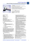
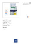
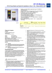
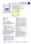
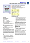
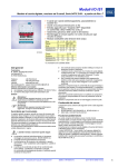
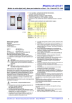
1
IS1 CPU & Power Module Ethernet CPU Modul & Power Modul Reihe 9441 und 9444 für Zone 2 ● Feldbusanschaltung Industrial Ethernet Modbus TCP oder EtherNet/IP mit 100 MBit/s ● Redundante Ethernet-Anschaltung möglich ● Explosionsgeschützter, optisch inherent sicherer Lichtwellenleiter, „Ex op is“ ● Integrierte Ex i Stromversorgung für bis zu 8 I/O Module ● Konfiguration und Diagnose über Ethernet und DTM ● LCD-Anzeige zur Anzeige von Diagnosedaten und für Systemeinstellungen ● Module unter Spannung in Zone 2 austauschbar (hot swap) Zonen 0 06457E00 Ethernet CPU Modul & Power Modul Reihe 9441 und 9444 für Zone 2 22 x Installation in X X X ✗ ✗ ✗ Weitere Informationen zum Modul finden Sie ✗ im Automatisierungskatalog (168465 / 00 006 54 78 0) oder ✗ im Internet unter www.stahl-automatisierung.de Symbole Achtung! Diese Grafik kennzeichnet Hinweise, bei deren Nichtbeachtung Ihre Gesundheit oder die Funktionsfähigkeit des Gerätes bzw. der Komponente gefährdet ist. Hinweis Diese Grafik kennzeichnet wichtige Zusatzinformationen, Tipps und Empfehlungen. Sicherheitshinweise In diesem Kapitel sind die wichtigsten Sicherheitsmaßnahmen zusammengefasst. Es ergänzt die entsprechenden Vorschriften, zu deren Studium das verantwortliche Personal verpflichtet ist. Bei Arbeiten in explosionsgefährdeten Bereichen hängt die Sicherheit von Personen und Anlagen von der Einhaltung aller relevanten Sicherheitsvorschriften ab. Das Montage- und Wartungspersonal trägt deshalb eine besondere Verantwortung. Voraussetzung ist die genaue Kenntnis der geltenden Vorschriften und Bestimmungen. Beachten Sie als Anwender: ✗ 21 X Telefon:+49 7942 943-0 Telefax:+49 7942 943-4333 Internet:www.stahl.de Service&Support:[email protected] Weitere Informationen zum Modul ✗ 20 X Hersteller R. STAHL Schaltgeräte GmbH Am Bahnhof 30 74638 Waldenburg, Germany ✗ ✗ 2 Ex Schnittstelle Allgemeine Angaben ✗ 1 die nationalen Sicherheits-, Unfallverhütungs-, Montage- und Errichtungsvorschriften (z.B. IEC/EN 60079-14) die allgemein anerkannten Regeln der Technik die Sicherheitshinweise und Angaben dieses Dokuments, die Kennwerte der Typschilder und die Hinweisschilder die in der EG-Baumusterprüfbescheinigung KEMA 10ATEX0118 X angegebenen Elektrischen Daten und besonderen Bedingungen für die sichere Anwendung. Diese gelten entsprechend auch für die IECEx-Zulassung. dass Beschädigungen den Explosionsschutz aufheben können www.stahl-ex.com Betriebsanleitung für CPU & Power Module ✗ ✗ ✗ ✗ ✗ ✗ ✗ ✗ dass die CPU & Power Module für den Einsatz in explosionsgefährdeten Bereichen der Zonen 2, 21 und 22 zugelassen sind, wenn sie in ein Stahl- oder Edelstahlgehäuse eingebaut sind, das die Anforderungen einer anerkannten Schutzart gemäß IEC/EN 60079-0 für den jeweiligen Installationsort erfüllt (z. B. R. STAHL 8126 oder 8150). dass beim Einsatz in staubexplosionsgefährdeten Bereichen, vor dem Öffnen des Gehäuses sichergestellt sein muss, dass kein explosionsfähiges Staub-Luft-Gemisch vorhanden ist. dass vor Arbeiten im Inneren des Gehäuses sichergestellt sein muss, dass es zu keiner elektrostatischen Entladung kommt. Deshalb vor Arbeiten im inneren des Gehäuses das Gehäuse berühren, um gegebenenfalls vorhandene elektrostatische Ladungen abzuleiten. dass alle Anschlüsse ausschließlich mit den von R. STAHL Schaltgeräte GmbH für den jeweiligen Anschluss freigegebenen Komponenten betrieben werden dürfen. dass beim Einbau in ein Gehäuse die zulässige Umgebungstemperaturen aller eingebauten Geräte nicht überschritten werden dürfen. Beachten Sie zusätzlich zur Erwärmung des Gehäuses durch eingebaute Geräte auch die Erwärmung durch äußere Einflüsse, wie z. B. durch Sonneneinstrahlung. dass beim Betrieb in bzw. mit explosionsgefährdeten Bereichen die DIN-Schiene der BusRail mit dem Potentialausgleich des explosionsgefährdeten Bereichs verbunden werden muss! dass der Kabelschwanz des Sockels in Zone 2 unter Spannung ohne spezielle Genehmigung weder angeschlossen noch getrennt werden darf! dass der Kabelschwanz des Sockels mit geeignetem Knickschutz und geeigneter Zugentlastung montiert werden muss. dass die freien Leitungsenden des Kabelschwanzes in einem geeigneten, bescheinigten Anschlussgehäuse angeschlossen werden müssen. dass CPU & Power Modul während des Betriebs gesteckt und entfernt werden dürfen. Bei entfernten Modulen hat der Sockel die Schutzart IP30. dass das CPU Modul, das Power Modul und der Sockel nur mit einem feuchten Tuch gereinigt werden dürfen. Verwenden Sie die Komponenten bestimmungsgemäß nur für den zugelassenen Einsatzzweck (siehe Kapitel „Funktion/ Eigenschaften“). Fehlerhafter und unzulässiger Einsatz sowie das Nichtbeachten der Hinweise dieses Dokuments schließen eine Gewährleistung unsererseits aus. Veränderungen an den Komponenten, die den Explosionsschutz betreffen, sind nicht gestattet. Komponenten dürfen nur in unbeschädigtem, trockenem und sauberen Zustand eingebaut werden. 203877/ 944160310090 2012-09-13·BA00·III·de·00 1 IS1 CPU & Power Module Ethernet CPU Modul & Power Modul Reihe 9441 und 9444 für Zone 2 Funktion/Eigenschaften Power Modul 9444 und CPU Modul 9441: Das CPU-Modul (CPU) hat die Funktion eines Gateways zwischen dem internen Bus einer IS1 Feldstation und dem explosionsgeschützten (Ex op is) Ethernet Modbus TCP bzw. EtherNet/IP. Das Power Modul (PM) enthält ein Netzteil zur eigensicheren Stromversorgung des CPU-Moduls und bis zu 8 I/O-Modulen inkl. der angeschlossenen Feldgeräte. Die Versorgung und Kommunikation der I/O-Module erfolgt über die BusRail. Die Elektronik ist druckfest gekapselt und über Steckverbinder Ex d und Ex i mit dem Sockel verbunden. Durch eine spezielle Mechanik kann sowohl das CPU-Modul (eigensichere Versorgung) als auch das Power Modul im Betrieb in der Zone 2 getauscht werden. 9 Power Modul 9444 Komponenten 10 LED „PWR IN“ (grün) externe Hilfsenergie i.O./n.i.O. „PWR OUT“ (grün) Ausgang Power Modul i.O./n.i.O. (Beschreibung der LED Anzeigen siehe „LED Anzeigen und Fehlerbehebung, S. 13) (9) (13) 11965E00 Sockel 9492 (simplex bzw. redundant): (1) (3) (12) (10) Übersicht (2) (11) 11 CPU Modul 12 LED „LINK“ (grün) „RUN“ (grün) „ERR“ (rot) (4) (5) 13 Status Ethernet Betrieb CPU i.O. Betrieb CPU, IOM n.i.O. (Beschreibung der LED Anzeigen siehe „LED Anzeigen und Fehlerbehebung, S. 13) LC-Buchse für LWL-Anschluss LC-Buchse für LWL-Anschluss (13): (6) (7) B (14) A (8) 12331E00 Anschluss 11964E00 1 Steckplatz für vertikalen BusRail-Anschluss (X6) 2 reserviert 3 Steckplatz für CPU Modul 4 Steckplatz für Power Modul 5 Steckplatz für horizontalen BusRail-Anschluss (X5) 6 Montagebohrungen (4x) „A“ TX „B“ RX Anschlussleitung für Hilfsenergie (8): 7 LCD-Anzeige mit Tastenfeld 8 Anschlussleitung für Hilfsenergie 24 V DC 14 Verriegelung Power Modul Adernbeschriftung Anschluss 1 Versorgungsspannung „+24 V“ 2 Versorgungsspannung „GND“ LCD-Anzeige mit Tastenfeld (7): CPU 0-0: IpAdr 192.23.121.7 LCD Esc 12329E00 2 2012-09-13·BA00·III·de·00 203877/ 944160310090 Betriebsanleitung für CPU & Power Module www.stahl-ex.com IS1 CPU & Power Module Ethernet CPU Modul & Power Modul Reihe 9441 und 9444 für Zone 2 Projektierung ✗ ✗ Montage und Installation Die nationalen Errichtungsbestimmungen (z. B. IEC/EN 60079-14) müssen beachtet werden. Die nationalen Errichtungsbestimmungen (z. B. IEC/EN 60079-14) müssen beachtet werden. Eigensichere und nicht-eigensichere Stromkreise dürfen nicht in einem gemeinsamen Kabelkanal geführt werden! Eigensichere und nicht-eigensichere Stromkreise dürfen nicht in einem gemeinsamen Kabelkanal geführt werden! Zwischen Anschlussteilen eigensicherer und nichteigensicherer Stromkreise muss ein Abstand von mindestens 50 mm (Fadenmaß) eingehalten werden! Zwischen Anschlussteilen eigensicherer und nichteigensicherer Stromkreise muss ein Abstand von mindestens 50 mm (Fadenmaß) eingehalten werden! Das Modul ist für IS1 Feldstationen bestimmt und darf in explosionsgefährdeten Bereichen der Zone 2/Division 2, Zone 21 oder Zone 22 installiert werden. Der Betrieb des Moduls ist nur vertikal zulässig: Montagerichtung oben Die Anschlussleitung für Hilfsenergie (8) darf ohne spezielle Genehmigung nur im spannungsfreien Zustand angeschlossen oder getrennt werden! Sockel montieren Der Betrieb des Moduls ist nur in folgender Montagelage zulässig: Sockel senkrecht, LCD-Display unten. Der Sockel muss auf einer ebenen Fläche, z.B. einer Montageplatte, montiert werden! Weitere Einbaubedingungen siehe Kapitel „Projektierung“ und „Technische Daten“. ✗ ✗ ✗ Bei Installation in explosionsgefährdeten Bereichen muss das Modul in ein Gehäuse eingebaut werden, das die Anforderungen einer anerkannten Schutzart gemäß IEC/EN 60079-0 erfüllt (z.B. R. STAHL Typ 8126 oder 8150). Alle Anschlüsse dürfen ausschließlich mit den von R. STAHL Schaltgeräte GmbH für den jeweiligen Anschluss freigegebenen Komponenten betrieben werden! Die Luftzirkulation in der Umgebung von CPU und Power Modul darf durch zusätzliche Einbauten nicht behindert werden! Der Abstand zwischen CPU & Power Modul und Umgehäuse muss mindestens 20 mm betragen! Der Sockel und die DIN-Schiene der BusRail sollten ohne Distanzhülsen direkt mit einer mindestens 2 mm dicken Montageplatte verschraubt werden. Diese muss so befestigt werden, dass bei Vibrationsbeanspruchung auf einer Länge von 500 mm eine Durchbiegung von maximal 2 mm entsteht. 36 mm / 1.42 " 35 mm / 1.38 " 314 mm / 12.36 " 258 mm / 10.16 " ✗ 173 mm / 6.81 " 12332E00 07820E00 www.stahl-ex.com Betriebsanleitung für CPU & Power Module 203877/ 944160310090 2012-09-13·BA00·III·de·00 3 IS1 CPU & Power Module Ethernet CPU Modul & Power Modul Reihe 9441 und 9444 für Zone 2 CPU Modul montieren: ● CPU Modul (11) senkrecht auf Steckplatz des Sockels stecken. ● Befestigungsschrauben des Moduls mit Schraubendreher (Innensechskant, Größe 3) anziehen (Anzugsdrehmoment: 2,6 Nm). 140 102,5 62,5 32,5 BusRail 62,5 51,5 CPU Modul wechseln: ● Stecker des Lichtwellenleiters an Buchse ausstecken. ● Befestigungsschrauben des Moduls mit Schraubendreher (Innensechskant, Größe 3) lösen. ● CPU Modul senkrecht aus dem Sockel ziehen. ● Neues CPU Modul senkrecht auf Steckplatz des Sockels stecken. ● Befestigungsschrauben des Moduls mit Schraubendreher (Innensechskant, Größe 3) anziehen (Anzugsdrehmoment: 2,6 Nm). ● Stecker des Lichtwellenleiters an Buchse einstecken. BusRail montieren 102,5 BusRail 245 M5 • Sockel mit 4 Schrauben M5 an Montageplatte befestigen (Anzugsdrehmoment: 2,6 Nm). Power Modul und CPU Modul montieren/wechseln 12333E00 Lichtwellenleiter des CPU Moduls nicht beschädigen! Das Wechseln des Power Moduls und des CPU Moduls ist auch in Zone 2 unter Spannung zulässig (hot swap)! Bei Installation des redundanten Sockels sind die Schritte zum Montieren und Wechseln des Powerbzw. CPU-Modules analog der unten aufgeführten. Bei Montage im explosionsgefährdeten Bereich bzw. bei Betrieb mit explosionsgeschützten Betriebsmitteln muss die DIN-Schiene mit dem Potentialausgleich des explosionsgeschützten Bereichs verbunden werden! Das Ende eines BusRail-Segments muss mit einem BusRail Abschluss, der BusRail-Verlängerung Typ 9494/A1-E0 oder der BusRail-Verlängerung Typ 9494/L1-V abgeschlossen werden! Bei redundantem Sockel ist die Klemme X6 nur oberhalb des rechten Steckplatzes des Sockels verfügbar! Die BusRail kann entweder an der Klemme X5 oder an der Klemme X6 (siehe Komponentenübersicht Seite 2) angeschlossen werden. Der gleichzeitige Betrieb von BusRails an der Klemme X5 und der Klemme X6 ist nicht zulässig! Der BusRail-Anschluss kann entweder direkt oder über ein Verbindungskabel (Typ 9494/L1-V) erfolgen. Zum direkten BusRail-Anschluss an den Sockel kann sowohl die BusRail 9494/S1-M4 (4 Module), als auch die BusRail 9494/S1-E2 (2 Module) verwendet werden. (9) (11) Weitere Angaben zur BusRail-Montage siehe Betriebsanleitung der BusRail. BusRail direkt montieren: (12) (16) (15) (14) (8) (16) 12334E00 Power Modul montieren: ● Roten Schieber (14) in Position „1“ schieben. ● Power Modul (9) senkrecht auf Steckplatz des Sockels stecken und einrasten. ● Befestigungsschrauben des Moduls mit Schraubendreher (Innensechskant, Größe 3) anziehen (Anzugsdrehmoment: 2,6 Nm). Power Modul wechseln: ● Befestigungsschrauben des Moduls mit Schraubendreher (Innensechskant, Größe 3) lösen. ● Roten Schieber (14) in Position „2“ schieben und Power Modul bis zur Zwischenstufe aus dem Sockel ziehen. ● Roten Schieber (14) in Position „3“ schieben und Power Modul senkrecht aus dem Sockel ziehen. 4 2012-09-13·BA00·III·de·00 203877/ 944160310090 (15) 12335E00 ● Klemmschraube (15) der Klemme (X5 oder X6) öffnen und Klemmenabdeckung (16) entfernen. Betriebsanleitung für CPU & Power Module www.stahl-ex.com IS1 CPU & Power Module Ethernet CPU Modul & Power Modul Reihe 9441 und 9444 für Zone 2 (23) (22) (17) (18) (19) (19) (20) (24) (21) (25) (26) 12336E00 ● DIN-Schiene (17) in Klemme (X5 oder X6) stecken und mit der Montageplatte verschrauben (Anzugsdrehmoment: 2,6 Nm). ● BusRail-Teilstück (18) in DIN-Schiene einlegen und vorsichtig auf die Klemme schieben. ● Erdungsklammern (19) über DIN-Schiene clipsen. ● I/O-Modul auf den ersten Steckplatz setzen, um die Position der BusRail zum Sockel zu kontrollieren. Die BusRail ist richtig eingerastet, wenn das I/O-Modul direkt am Sockel anliegt. ● Gegebenenfalls Erdungsklammern (19) lösen, Position der BusRail korrigieren und Erdungsklammern wieder über DINSchiene clipsen. ● Klemmschraube (15) der Klemme (X5 oder X6) anziehen (Anzugsdrehmoment: 2 Nm). ● BusRail-Abschluss (20) am Ende des BusRail-Teilstücks montieren. BusRail über Verbindungskabel (Typ 9494/L1-V) montieren: (16) (15) 12337E00 ● DIN-Schienenstück (21) in Klemme (X5 oder X6) stecken und mit der Montageplatte verschrauben (Anzugsdrehmoment 2,6 Nm). ● Abschluss Beginn (22) des Verbindungskabels auf die DINSchiene setzen und vorsichtig auf die Klemme schieben. ● Klemmschraube (23) anziehen (Anzugsdrehmoment: 2 Nm). ● Klemmschraube (15) der Klemme (X5 oder X6) anziehen (Anzugsdrehmoment: 2 Nm). ● Abschluss Ende (24) des Verbindungskabels mit der BusRail (25) verbinden. ● Klemmschraube (23) anziehen (Anzugsdrehmoment: 2 Nm). CPU & Power Modul anschließen Die nationalen Errichtungsbestimmungen (z. B. IEC/EN 60079-14) müssen beachtet werden! Eigensichere und nicht-eigensichere Stromkreise dürfen nicht in einem gemeinsamen Kabelkanal geführt werden! Zwischen Anschlussteilen eigensicherer und nichteigensicherer Stromkreise muss ein Abstand von mindestens 50 mm (Fadenmaß) eingehalten werden! Die Anschlussleitung für Hilfsenergie (8) darf nur im spannungsfreien Zustand angeschlossen oder getrennt werden! (16) (15) Schutzkappen von LC-Stecker und LC-Buchse dürfen erst unmittelbar vor dem Stecken entfernt werden, um Verschmutzung der Faserenden zu vermeiden! LWL anschließen: Der LWL muss bei redundanten Modulen an beiden CPU-Modulen angeschlossen werden! 12335E00 ● Klemmschraube (15) der Klemme (X5 oder X6) öffnen und Klemmenabdeckung (16) entfernen. B A 12331E00 ● Schutzkappen von Stecker und Buchse entfernen. ● Stecker des Lichtwellenleiters in Buchse stecken bis er einrastet. ● LWL so verlegen, dass die minimalen Biegeradien (< 30 mm statisch, < 60 mm dynamisch) nicht unterschritten werden und er gegen Zugbelastungen und Scheuern geschützt ist. www.stahl-ex.com Betriebsanleitung für CPU & Power Module 203877/ 944160310090 2012-09-13·BA00·III·de·00 5 IS1 CPU & Power Module Ethernet CPU Modul & Power Modul Reihe 9441 und 9444 für Zone 2 Hilfsenergie anschließen: Die Hilfsenergie muss bei redundanten Modulen an beiden Hilfsenergie-Zuleitungen (Pos. 8) angeschlossen werden! Die Anschlussleitung darf bei Zone 2 / 22 Installation nur an Ex e / Ex nA Klemmen gemäß IEC/EN 60079-7 bzw. IEC/EN 60079-15 angeschlossen werden! Anschlusshinweise des Klemmenherstellers beachten! ● Anschlussleitungen des Sockels gemäß folgender Tabelle anschließen: Adernbeschriftung Anschluss 1 Versorgungsspannung „+ 24 V“ 2 Versorgungsspannung „GND“ ● Anschlussleitung so verlegen, dass sie gegen Zugbelastungen und Scheuern geschützt ist. 6 2012-09-13·BA00·III·de·00 203877/ 944160310090 Betriebsanleitung für CPU & Power Module www.stahl-ex.com IS1 CPU & Power Module Ethernet CPU Modul & Power Modul Reihe 9441 und 9444 für Zone 2 Parametrierung und Inbetriebnahme Die Parametrierung und Inbetriebnahme der CPU erfolgt über den IS1 DeviceDTM. Über die LCD-Anzeige mit Tasten im Sockel lassen sich - Diagnosedaten des CPU Moduls anzeigen (sowohl Primär- als auch Backup-CPU), - die Kommunikationsadressen des CPU Moduls (sowohl Primär- als auch Backup-CPU) einstellen und - Informationen über das CPU Modul (sowohl Primär- als auch Backup-CPU) und die auf der BusRail installierten I/O-Module anzeigen. Änderungen der IP-Adresse und der SubNet-Maske kann zu Kommunikationsverlusten über Ethernet führen! Änderungen der Kommunikationsadressen haben eine sofortige Auswirkung auf das Systemverhalten und können zu einer Fehlfunktion des Systems führen! Änderungen der Kommunikationsadressen dürfen nur durch geschultes und autorisiertes Servicepersonal vorgenommen werden! CPU 0-0:Format < ¿ > CPU 0-0:Protocol Modbus TCP SLOT 8: AOM module OK/mode:0 SLOT 8: AOM 9465/12-08-11 CPU 0-0:SWITCH < ¿ > CPU 0-0: Service 5 CPU 0-0:EXPERT < ¿ > CPU 0-0:Address < ¿ > CPU 0-0: Port S:50000 H: 50001 CPU 0-0:SAVEDIAG < ¿ > CPU 0-0:SNR 123456-6789 CPU 0-0: MacAdr 001DF7:00:00:02 CPU 0-0: Gateway 192.23.121.100 Modbus TCP 20-01 (00-28) CPU 0-0:Revision FW 20-01, HW !A" CPU 0-1: - - - CPU 0-0: SubNet 255.255.248.0 Oct 13 2008 13:01:05 !up" !dwn" !enter" !escape" slot 1: DOM 9475/12-08-51 CPU 0-0: primary 9441/12-00-00 CPU 0-0: IpAdr 192.23.121.7 IS1 Ethernet CPU R. STAHL, Germany StartUp Systemebene Modulebene Informations-/ Serviceebene CPU 0-0:PASSWORD # # # # CPU 0-0:Simulate < ¿ > CPU 0-0:Status QuitDataExch Expertenebene Ebenenübersicht 12341E00 www.stahl-ex.com Betriebsanleitung für CPU & Power Module 203877/ 944160310090 2012-09-13·BA00·III·de·00 7 IS1 CPU & Power Module Ethernet CPU Modul & Power Modul Reihe 9441 und 9444 für Zone 2 LCD-Anzeige mit Tastenfeld: Tastenbelegung Taste Bezeichnung Funktion ESC „esc“ „dwn“ wechselt von aktueller in nächsthöhere Menüebene wechselt innerhalb einer Menüebene zwischen den verschiedenen Untermenüs verringert bei Eingabe einen Zahlenwert „up“ wechselt innerhalb einer Menüebene zwischen den verschiedenen Untermenüs Modulebene In der Modulebene werden die Module auf der BusRail angezeigt. Die Modulebene wird durch <enter> aus der Systemebene aufgerufen. Der Sockel hat die Steckplatzadresse 0, die I/O-Module beginnen mit dem Steckplatz 1. Es werden alle gesteckten Module erkannt, unabhängig davon, ob sie konfiguriert sind oder nicht. LCD-Anzeige Anzeige/Funktion CPU 0-0: primary 9441/12-00-00 12303E00 erhöht bei Eingabe einen Zahlenwert „enter“ Wechsel in die Informations-/ Serviceebene des ausgewählten Moduls durch Drücken von <enter>. wechselt von aktueller in nächsttiefere Menüebene wechselt in nachgeordnetes Untermenü übernimmt geänderte Parameter Anzeige des vorhandenen CPU Typs und dessen Status („primary“, „backup“ oder „noBackup“) nur bei redundantem CPU-Modul CPU 0-1: - - - 12304E00 StartUp Nach Anlegen der Hilfsenergie bootet das CPU & Power Modul und zeigt im Display die Version des Boot-Programmes an (z. B. boot (00-38)). Nach erfolgreichem Bootvorgang wechselt die LCD-Anzeige in die Systemebene und zeigt nacheinander folgende Informationen an. LCD-Anzeige Anzeige/Funktion IS1 Ethernet CPU R. STAHL, Germany Modulname und Hersteller Kopplungsart, Firmware-Version und Version des Bootprogramms 12298E00 Erstelldatum der Firmware Oct 13 2008 13:01:05 12299E00 IP-Adresse Bei erfolgreichem Bootvorgang bleibt diese Anzeige stehen. Bei redundanten Systemen kann die CPU als „0-1“ angezeigt werden, wenn diese „Primary“ ist. Systemebene In der Systemebene werden die aktuellen Kommunikationsadressen des CPU & Power Moduls angezeigt. Durch Drücken der Tasten „up“ oder „dwn“ kann zwischen folgenden Anzeigen gewechselt werden: LCD-Anzeige Wechsel in die Informations-/ Serviceebene des ausgewählten Moduls durch Drücken von <enter>. slot 2: --< no module > kein I/O-Modul auf Steckplatz 2 der BusRail vorhanden Informations-/ Serviceebene In der Informations-/ Serviceebene können detaillierte Informationen zu den Modulen angezeigt und die Kommunikationsadressen des CPU & Power Moduls geändert werden (siehe „Modulabhängige Informationen anzeigen“). Expertenebene 12297E00 CPU 0-0: IpAdr 192.23.121.7 12306E00 Anzeige des vorhandenen I/O-Modul Typs auf Steckplatz 1 der BusRail 12307E00 12296E00 Modbus TCP 20-01 (00-28) slot 1: DOM 9475/12-08-51 Änderungen in der Expertenebene haben Auswirkungen auf die Funktionsfähigkeit des CPU & Power Moduls! Änderungen in der Expertenebene dürfen nur durch geschultes und autorisiertes Servicepersonal vorgenommen werden! Der Wechsel in die Expertenebene ist passwortgeschützt. Anzeige/Funktion IP-Adresse CPU 0-0: IpAdr 192.23.121.7 12299E00 SubNet-Maske CPU 0-0: SubNet 255.255.248.0 122300E00 CPU 0-0: Gateway 192.23.121.100 Default Gateway 12473E00 MAC-Adresse CPU 0-0: MacAdr 001DF7:00:00:02 122301E00 Portnummern für ServiceBus und HART socket CPU 0-0: Port S:50000 H:50001 12527E00 CPU 0-0: Service 5 ServiceBus-Adresse (Derzeit nicht implementiert.) 122302E00 8 2012-09-13·BA00·III·de·00 203877/ 944160310090 Betriebsanleitung für CPU & Power Module www.stahl-ex.com IS1 CPU & Power Module Ethernet CPU Modul & Power Modul Reihe 9441 und 9444 für Zone 2 Kommunikationsadressen des CPU & Power Moduls ändern bzw. aktivieren Änderungen an der IP-Adresse, der SubNet-Maske oder des Default Gateways können zu Kommunikationsverlusten über Ethernet führen! Änderungen der Kommunikationsadressen haben eine sofortige Auswirkung auf das Systemverhalten und können zu einer Fehlfunktion des Systems führen! Änderungen der Kommunikationsadressen dürfen nur durch geschultes und autorisiertes Servicepersonal vorgenommen werden! Geänderte Kommunikationsadressen sind sofort nach der Änderung aktiv. Sie sind permanent gespeichert und stehen auch nach Reset oder Wiederinbetriebnahme zur Verfügung. Das Untermenü für die Adresseinstellungen kann nur aufgerufen werden, wenn sich die Ethernet CPU nicht im Zustand Data Exchange befindet. Wechselt die Ethernet CPU in den Zustand Data Exchange, während das Untermenü geöffnet ist, wird dieses beendet. Es erscheint folgende Anzeige: CPU 0-0: < exit submenu > 12328E00 Die Änderung der Adresse kann jederzeit durch Drücken der Taste „esc“ abgebrochen werden. ● Taste „up“ oder „dwn“ so oft drücken, bis gewünschter Wert eingestellt ist. Bei dauerndem Drücken der Taste wird der Wert schnell geändert (fortlaufend). ● ✔ ✔ ✔ Taste „enter“ drücken. Die Änderung des ersten Adressblocks wird übernommen. Der zweite Adressblock wird markiert. Es erscheint folgende Anzeige: IpAdr change 192 23 121. 7 ● Zweiten bis vierten Adressblock analog zum ersten Adressblock ändern. ● Taste „enter“ drücken. ✔ Es erscheint folgende Anzeige: 12277E00 accept changes ? no yes< > ● Taste „enter“ drücken, um Änderung der Adresse zu bestätigen bzw. Taste „esc“ drücken um Änderung der Adresse abzubrechen. ✔ Die Anzeige wechselt zurück ins Hauptmenü der Informations-/Serviceebene 12313E00 Subnet Maske ändern ● Taste „enter“ zweimal drücken, um von Systemebene in Informations-/Serviceebene zu wechseln. ● Taste „enter“ einmal drücken,wenn im Display „CPU 0-0: primary; 9441/12-00-00“ angezeigt wird, um von Systemebene in Informations-/Serviceebene zu wechseln. ✔ Es erscheint folgende Anzeige: CPU 0-0:Status NoDataExch Es erscheint folgende Anzeige: 12309E00 ● Taste „up“ oder „dwn“ so oft drücken, bis folgende Anzeige erscheint: discard changes? no yes< > CPU 0-0:Address < > 12308E00 Durch Drücken der Taste „enter“ wechselt die Anzeige zurück ins Hauptmenü der Informations-/ Serviceebene. IP-Adresse ändern ● Taste „enter“ zweimal drücken, um von Systemebene in Informations-/Serviceebene zu wechseln. ● Taste „enter“ einmal drücken,wenn im Display „CPU 0-0: primary; 9441/12-00-00“ angezeigt wird, um von Systemebene in Informations-/Serviceebene zu wechseln. ✔ Es erscheint folgende Anzeige: 12310E00 ● Taste „enter“ drücken. ✔ Es erscheint folgende Anzeige: IpAdr < 192. 23.121.7 > 12311E00 ● Taste „up“ oder „dwn“ so oft drücken, bis folgende Anzeige erscheint: SubNet < 255.255.255.0 > 12314E00 CPU 0-0:Status NoDataExch 12309E00 ● Taste „up“ oder „dwn“ so oft drücken, bis folgende Anzeige erscheint: CPU 0-0:Address < > ● Taste „enter“ drücken. ✔ Es erscheint folgende Anzeige: IpAdr < 192. 23.121.7 Einstellbare Werte: 255 254 252 248 240 224 192 128 12311E00 change 23.121. 7 12330E00 12315E00 ● ✔ ✔ ● Taste „enter“ drücken. Die Änderung des ersten Adressblocks wird übernommen. Der zweite Adressblock wird markiert. Zweiten bis vierten Adressblock analog zum ersten Adressblock ändern. ● Taste „enter“ drücken. ✔ Es erscheint folgende Anzeige: accept changes ? no yes< > ● Taste „enter“ drücken, um Änderung der Adresse zu bestätigen. ✔ Die Anzeige wechselt zurück ins Hauptmenü der Informations-/Serviceebene www.stahl-ex.com 0 ◄: ►: > ● Taste „enter“ drücken. ✔ Der erste Adressblock wird markiert. ✔ Es erscheint folgende Anzeige: IpAdr 192 12310E00 ● Taste „enter“ drücken. ✔ Der erste Adressblock wird markiert. ● Taste „up“ oder „dwn“ so oft drücken, bis gewünschter Wert eingestellt ist. Betriebsanleitung für CPU & Power Module 203877/ 944160310090 12313E00 2012-09-13·BA00·III·de·00 9 IS1 CPU & Power Module Ethernet CPU Modul & Power Modul Reihe 9441 und 9444 für Zone 2 Default Gateway ändern Die Einstellung des Default Gateway ist notwendig, um von anderen Ethernet-Netzen Zugriff auf die CPU zu erhalten. Ohne Default Gateway antwortet die CPU nur auf Telegramme der durch IP-Adresse und Subnet Maske definierten eigenen Netzadresse. Das Default Gateway muss sich im selben Netz wie die CPU befinden. Im Auslieferzustand ist kein Gateway eingestellt. Vor der Einstellung des Default Gateways wird ein Startwert aus IP-Adresse und Subnet Maske ermittelt. Dieser Startwert muss an den Default Gateway der Anlage angepasst werden. ● Taste „enter“ zweimal drücken, um von Systemebene in Informations-/Serviceebene zu wechseln. ● Taste „enter“ einmal drücken,wenn im Display „CPU 0-0: primary; 9441/12-00-00“ angezeigt wird, um von Systemebene in Informations-/Serviceebene zu wechseln. ✔ Es erscheint folgende Anzeige: CPU 0-0:Status NoDataExch 12309E00 ● Taste „up“ oder „dwn“ so oft drücken, bis folgende Anzeige erscheint: 12310E00 ● Taste „enter“ drücken. ✔ Es erscheint folgende Anzeige: 12311E00 12474E00 ● Taste „enter“ drücken. ✔ Es erscheint folgende Anzeige: Vor dem Ändern der Porteinstellungen sicherstellen, dass der gewünschte Port nicht bereits von anderen Applikationen in der Anlage verwendet wird. Die Porteinstellungen müssen mit den Einstellungen im DTM übereinstimmen. Die Ports sind im Bereich von 0 ... 65535 einstellbar. ● Taste „enter“ zweimal drücken, um von Systemebene in Informations-/Serviceebene zu wechseln. ● Taste „enter“ einmal drücken,wenn im Display „CPU 0-0: primary; 9441/12-00-00“ angezeigt wird, um von Systemebene in Informations-/Serviceebene zu wechseln. ✔ Es erscheint folgende Anzeige: 12309E00 ● Taste „up“ oder „dwn“ so oft drücken, bis folgende Anzeige erscheint: ● Taste „enter“ drücken. ✔ Es erscheint folgende Anzeige: ● Taste „enter“ drücken. ✔ Der erste Adressblock wird markiert. ✔ Es erscheint folgende Anzeige: 12475E00 > 12311E00 < > ● Taste „enter“ drücken. ✔ Es erscheint folgende Anzeige: Pt HART 50001 Gateway change 192 23.121.100 12310E00 ● Taste „up“ oder „dwn“ so oft drücken, bis folgende Anzeige erscheint: Pt HART 50001 Gateway < > 192. 23.121.100 12478E00 change 12479E00 12476E00 ● Taste „up“ oder „dwn“ so oft drücken, bis gewünschter Wert eingestellt ist. Bei dauerndem Drücken der Taste wird der Wert schnell geändert (fortlaufend). Taste „enter“ drücken. Die Änderung des ersten Adressblocks wird übernommen. Der zweite Adressblock wird markiert. Es erscheint folgende Anzeige: Gateway change 192 23 121.100 ● Zweiten bis vierten Adressblock analog zum ersten Adressblock ändern. ● Taste „enter“ drücken. ✔ Es erscheint folgende Anzeige: 12477E00 ● Taste „up“ oder „dwn“ so oft drücken, bis gewünschter Wert eingestellt ist. Bei dauerndem Drücken der Taste wird der Wert schnell geändert (fortlaufend). ● Taste „enter“ drücken. ✔ Es erscheint folgende Anzeige: accept changes ? no yes< > 12313E00 ● Taste „enter“ drücken, um Änderung des Ports zu bestätigen bzw. Taste „esc“ drücken um Änderung des Ports abzubrechen. ✔ Die Anzeige wechselt zurück ins Hauptmenü der Informations-/Serviceebene Redundanzbetrieb Umschalten zwischen „Primary“ und „Backup“ accept changes ? no yes< > 12313E00 2012-09-13·BA00·III·de·00 Änderungen der Porteinstellungen dürfen nur durch geschultes und autorisiertes Servicepersonal vorgenommen werden! IpAdr < 192. 23.121.7 Gateway < > 192. 23.121.100 10 Änderungen der Porteinstellungen können Auswirkungen auf die Funktionsfähigkeit des Sockels haben! CPU 0-0:Address < > > ● Taste „up“ oder „dwn“ so oft drücken, bis folgende Anzeige erscheint: ● ✔ ✔ ✔ Port für azyklische HART Kommunikation einstellen CPU 0-0:Status NoDataExch CPU 0-0:Address < > IpAdr < 192. 23.121.7 ● Taste „enter“ drücken, um Änderung der Adresse zu bestätigen bzw. Taste „esc“ drücken um Änderung der Adresse abzubrechen. ✔ Die Anzeige wechselt zurück ins Hauptmenü der Informations-/Serviceebene 203877/ 944160310090 Die Slots 0-0 und 0-1 können, je nach Systemzustand, die Primary und Backup Funktion einnehmen. Zum Umschalten wie folgt vorgehen: Betriebsanleitung für CPU & Power Module www.stahl-ex.com IS1 CPU & Power Module Ethernet CPU Modul & Power Modul Reihe 9441 und 9444 für Zone 2 1 2 3 4 IP-Adresse der CPU 0-1 muss unterschiedlich zu der IP-Adresse von CPU 0-0 sein! • CPU 0-0 wieder in Slot 0-0 einsetzen. Informationen zu CPU, Sockel und Switch anzeigen ● Taste „enter“ drücken, um von Systemebene in Modulebene zu wechseln. ✔ Es erscheint folgende Anzeige: CPU 0-0:Status DataExch 12309E00 ● Mit der Taste „up“ oder „dwn“ gewünschtes Modul auswählen. ● Taste „enter“ drücken. ✔ Die Anzeige wechselt in die Informations-/Serviceebene. LCD-Anzeige 5 Anzeige/Funktion CPU 0-0:Status DataExch 12309E00 CPU 0-0:Protocol Modbus TCP Status des CPU Moduls (Mögliche Status-Informationen siehe Tabelle „StatusInformationen des CPU Moduls“)* Kopplungsart 12316E00 15121E00 1 Slot 0-1 2 CPU 0-1 3 Slot 0-0 4 CPU 0-0 5 Display und Tastatur für 0-0 und 0-1 CPU 0-0:Revision 20-01 (00-28)‘A’ 12317E00 Seriennummer des CPU Moduls CPU 0-0:SNo 123456-6789 • CPU und Power Module installieren (siehe Kapitel Montage und Installation). ● System booten (siehe Kapitel „Startup“) ✔ CPU 0-0 ist Primary und CPU 0-1 ist Backup. 12318E00 CPU 0-0: Socket < > 12305E00 Es kann nur die CPU 0-0 über das Display gesteuert bzw. parametriert werden. • Es erscheint folgende Anzeige: 12310E00 • Taste „enter“ drücken. ✔ Es erscheint folgende Anzeige: 15118E00 CPU 0-0:Switch < > CPU 0-0: primary 9441/12-00-00 ● Taste „up“ drücken. ✔ Es erscheint folgende Anzeige: 12528E00 12303E00 CPU 0-0:saveDiag < > CPU 0-1: noBackup 9441/12-00-00 12320E00 15119E00 „noBackup“: System ist nicht als redundantes System konfiguriert. „Backup“:System ist als redundantes System konfiguriert (über DTM). • Taste „up“ drücken. ✔ Es werden nacheinander alle Module im System angezeigt. ● Einstellungen der einzelnen Parameter, wie in den Kapiteln „IP-Adresse ändern„ und folgende beschrieben, anpassen. ● Taste „esc“ drücken. ✔ IP-Adresse wird angezeigt. ● CPU 0-0 aus dem Slot 0-0 entfernen. ✔ CPU 0-1 ist jetzt Primary und CPU 0-0 Backup. ✔ Es erscheint folgende Anzeige: CPU 0-1: IpAdr; 0.0.0.0 15120E00 Wechsel in die Informations-/ Serviceebene des Sockels. Dort werden folgende Informationen angezeigt: Typ, Hardware-Revision und Seriennummer des Sockels CPU 0-0:Address < > CPU 0-0: IpAdr; 0.0.0.0 Firmeware-Revision, Bootprogramm-Version und Hardware-Revision des CPU Moduls CPU 0-0:Expert < > 12322E00 ändern bzw. anzeigen (bei Backup-CPU) der Kommunikationsadressen (siehe „Kommunikationsadressen des CPU & Power Moduls ändern“) lesen einzelner Register des Switch Bausteins des CPU Moduls (siehe „Diagnosedaten des Ethernet Switch anzeigen“) manuelles Sichern der Diagnosedaten auf Flash-Speicher des CPU Moduls (siehe „Diagnosedaten manuell sichern“) (nur bei Primary-Modul möglich) wechseln in Expertenebene (siehe „Expertenebene“) (nur bei Primary-Modul möglich) * Status-Informationen des CPU Moduls: Status-Information in LCD-Anzeige Bedeutung Hardware Error Hardwarefehler gefunden DataExch CPU ist im Data Exchange, Konfiguration durch DTM NoDataExch CPU ist nicht im Data Exchange Config Error Konfigurationsfehler der CPU • Taste „enter“ drücken. ● Einstellungen der einzelnen Parameter, wie in den Kapiteln „IP-Adresse ändern „ ff beschrieben, anpassen. QuitDataExch Data Exchange verlassen DataExchConfigAs CPU ist im Data Exchange, Konfiguration durch Automatisierungssystem www.stahl-ex.com 203877/ 944160310090 Betriebsanleitung für CPU & Power Module 2012-09-13·BA00·III·de·00 11 IS1 CPU & Power Module Ethernet CPU Modul & Power Modul Reihe 9441 und 9444 für Zone 2 Informationen zu Input/Output Modulen anzeigen ● Taste „enter“ drücken, um von Systemebene in Modulebene zu wechseln. ✔ Es erscheint folgende Anzeige: Digital Output Module: Zusätzlich zu den allgemeinen Anzeigen gibt es beim Digital Output Modul noch folgende Anzeigen: LCD-Anzeige CPU 0-0:Address < > 12309E00 ● Mit der Taste „up“ oder „dwn“ gewünschtes Modul auswählen. ● Taste „enter“ drücken. ✔ Die Anzeige wechselt in die Informations-/Serviceebene. Output/Input Module allgemein: Anzeige/Funktion slot 1: DOM 1 1 0 0 1 0 1 1 12271E00 slot 1: DOM safety position 12272E00 Die folgenden Anzeigen sind für alle Output/Input Module gleich aufgebaut. LCD-Anzeige slot . . 1: . . DOM . . 12273E00 Anzeige/Funktion slot 2: AOM module OK/mode:0 12268E00 slot 1: AOM FW 02-04, HW ‘E’ Anzeige des Steckplatzes, des Modultyps und des Modulzustands**. Anzeige der Firmware- und der Hardvere-Revision. Anzeige der Seriennummer. ** mögliche Modulzustände: Status-Information Bedeutung in LCD-Anzeige IOM no response Kommunikation mit dem Modul ist nicht möglich. Modul ist defekt, nicht gesteckt oder beide BusRail bzw das BusRailVerbindungskabel sind gestört. hardware failure Modul meldet Hardwarefehler. conf unequal mod Konfigurationsfehler oder falsches Modul gesteckt. HW disable outp. Ausgänge durch externen Schalter (Anlagen Aus) abgeschaltet (nur bei DOM 9475/2) prim. Rail fail keine Kommunikation über primären BusRail-Datenbus red. Rail fail keine Kommunikation über redundanten BusRail-Datenbus module OK/mode: x Modul in Ordnung. Kein Modulfehler. Signalfehler können trotzdem vorhanden sein. Zusätzlich wird die konfigurierte Betriebsart (mode:x) angezeigt. 12274E00 Zusätzlich zu den allgemeinen Anzeigen gibt es beim Digital Input Modul noch folgende Anzeigen: Anzeige/Funktion slot 2: DIM 1100011011011010 12276E00 Prio 1 IO Fehler : Open Circuit : Short circuit Digital Input Module: LCD-Anzeige 12270E00 Ohne Ausgabedaten wird Sicherheitszustand der Ausgänge angezeigt. IO Daten und Fehler 1 1 0 0 1 0 1 1 . . . . . . 12269E00 slot 3: AOM SNo: 123456-7890 IO Daten. Der Wert für Kanal 0 steht links, der für Kanal 7 rechts. slot . . 1: . . DOM . . 12273E00 1100011011011010 . . . . . . IO Daten. Der Wert für Kanal 0 steht links, der für Kanal 15 rechts. IO Fehler : Open Circuit : Short circuit IO Daten und Fehler 12278E00 2 3 s 3/14: 0 Counter: reset 12279E00 4 s 3/15: 100 Counter: start 12280E00 5 Anzeige des Zähler-/ Frequenzwertes und der Steuerbits „start“ und „reset“ für Kanal 14. Anzeige des Zähler-/ Frequenzwertes und der Steuerbits „start“ und „reset“ für Kanal 15. 5 6 Bei mehreren Fehlern wird nur der Fehler mit der höchsten Priorität angezeigt. Nach Beheben dieses Fehlers wird der Fehler mit der nächsthöheren Priorität angezeigt. 12 2012-09-13·BA00·III·de·00 203877/ 944160310090 Betriebsanleitung für CPU & Power Module www.stahl-ex.com IS1 CPU & Power Module Ethernet CPU Modul & Power Modul Reihe 9441 und 9444 für Zone 2 Analog Output Modul/Analog Input Module: Das Menü für die Analog Output Module und die Analog Input Module ist gleich. Für die Module AOMH 9461, AOMH 9466 und TIM R 9480 gibt es noch zusätzliche Menüpunkte (siehe „Analog Module mit HART“ und „Temperatur Input Module“). LCD-Anzeige slot 3: Anzeige/Funktion AOM s s 12281E00 slot . . 3: . . AOM . . 12282E00 . . IO Fehler : Open Circuit : Short circuit IO Daten und Fehler s s . . . . IO Daten. Der Wert für Kanal 0 steht links, der für Kanal 7 rechts. Bei Ausgängen, die noch keine gültigen IO Daten erhalten haben, wird die Sicherheitsstellung ’s’ angezeigt. 12283E00 slot 3: single I/O AOM 12284E00 slot 3: AOM I/O 0: safety pos 12285E00 Anzeige der IO Daten für einzelne Kanäle. Aufruf des Untermenüs durch „enter“. Anzeige von IO Fehler oder IO Daten. Ist kein IO Wert vorhanden, wird die Sicherheitsstellung angezeigt. Wechseln zwischen Kanälen durch Drücken der Tasten „up“ oder „dwn“. Diagnosedaten des Ethernet Switch anzeigen ● Taste „enter“ zweimal drücken, um von Systemebene in Informations-/Serviceebene zu wechseln. ✔ Es erscheint folgende Anzeige: CPU 0-0:Status DataExch 12309E00 ● Taste „up“ oder „dwn“ so oft drücken, bis folgende Anzeige erscheint: CPU 0-0:Switch < > MIB Cntr Port 4 < > ● Taste „up“ oder „dwn“ drücken, um Port auszuwählen. ✔ Es erscheint folgende Anzeige: Das Untermenü erscheint nur, wenn die Analog Module für die Übertragung von HART PV konfiguriert sind. Es werden nur die konfigurierten HART PV angezeigt. LCD-Anzeige slot 4: HART PV ● Taste „up“ oder „dwn“ drücken, um zwischen den verschiedenen Registern zu wechseln. ● Taste „esc“ drücken, um Untermenü zu verlassen. 12286E00 slot 4: AIM PV 1: -16.234 12287E00 slot 4: PV 3: AIM #.### Menü zur Anzeige der HART PV. Aufruf der Untermenüs durch „enter“. Anzeige der konfigurierten PV. Betriebsart 1 = 4 PV, Betriebsart 2 = 8 PV. Wechseln der PV durch Drücken der Taste „up“ oder „dwn“. 12483E00 Zur Diagnose können für den Port 5 (Ethernet CPU) und den Port 4 (LWL-Hostanschluss) folgende MIB Counter Register angezeigt werden: 0x0B RxBroadcast Rx good broadcast packets (nicht enthalten: errored broadcast packets oder valid multicast packets) 0x0C RxMulticast Rx good multicast packets (nicht enthalten: MAC control frames, errored multicast packets oder valid broadcast packets) 0x0D RxUnicast Rx good unicast packets 0x12 Rx512to1023Octets Total Rx packets (bad packets enthalten) mit einer Länge von 512 bis 1023 octets 0x18 TxBroadcastPkts Tx good broadcast packets (nicht enthalten: errored broadcast oder valid multicast packets) 0x19 TxMulticastPkts Tx good multicast packets (nicht enthalten: errored multicast oder valid broadcast packets) 0x1A TxUnicastPkts Tx good unicast packets Anzeige/Funktion AIM 12482E00 MIB Cntr Port 5 Reg 0B->00000000 Analog Module mit HART: Für die HART Module 9461 und 9466 können die HART PV dargestellt werden. 12481E00 ● Taste „enter“ drücken. ✔ Es erscheint folgende Anzeige: Anzeige von „not a number“ 12288E00 www.stahl-ex.com Betriebsanleitung für CPU & Power Module 203877/ 944160310090 2012-09-13·BA00·III·de·00 13 IS1 CPU & Power Module Ethernet CPU Modul & Power Modul Reihe 9441 und 9444 für Zone 2 Diagnosedaten manuell sichern Die Diagnosedaten werden während des Betriebs im RAM gehalten. Alle 24 Stunden und bei schweren Fehlern werden die Diagnosedaten aus dem RAM in einen Flash Speicher gesichert. Gesicherte Diagnosedaten stehen auch nach Reset oder Wiederinbetriebnahme zur Verfügung. Soll ein CPU Modul vom Netz getrennt werden, ohne dass die Diagnosedaten verloren gehen, müssen diese manuell gesichert werden. ● Taste „enter“ zweimal drücken, um von Systemebene in Informations-/Serviceebene zu wechseln. ✔ Es erscheint folgende Anzeige: CPU 0-0:Status DataExch 12309E00 ● Taste „up“ oder „dwn“ so oft drücken, bis folgende Anzeige erscheint: ✔ Nur bei aktiver CPU möglich! CPU 0-0:saveDiag < > ● Taste „enter“ drücken, um Diagnosedaten manuell zu sichern. ✔ Es erscheint folgende Anzeige: 12320E00 CPU 0-0:saveDiag saving ... ● Taste „esc“ drücken, um Untermenü zu verlassen. 12327E00 Wartung und Instandhaltung Vor Arbeiten im inneren des Gehäuses sicherstellen, dass es zu keiner elektrostatischen Entladung kommt. Deshalb vor Arbeiten im inneren des Gehäuses das Gehäuse berühren, um gegebenenfalls vorhandene elektrostatische Ladungen abzuleiten. Das Modul ist wartungsfrei. Beachten Sie die bestimmungsgemäße Funktion. Halten Sie sich an die Richtlinien nach IEC/EN 60079-17. Reparatur Für die Reparatur schicken Sie das Modul an Ihre zuständige Vertriebsorganisation (Adresse siehe www.stahl.de). Die Reparatur darf nur durch den Hersteller durchgeführt werden! Transport und Lagerung Transport und Lagerung sind nur in Originalverpackung gestattet. Entsorgung Beachten Sie die nationalen Abfallbeseitigungsvorschriften! 14 2012-09-13·BA00·III·de·00 203877/ 944160310090 Betriebsanleitung für CPU & Power Module www.stahl-ex.com IS1 CPU & Power Module Ethernet CPU Modul & Power Modul Reihe 9441 und 9444 für Zone 2 LED Anzeigen und Fehlerbehebung Power-Modul LED grün “PWR IN“ LED grün “PWR OUT“ Modul Zustand Fehlerquelle Mögliche Behebung Ein Ein • Eingangs- und Ausgangsspannung sind in Ordnung • Modul ist in Ordnung keine -- Ein Aus • Eingangsspannung ist in Ordnung • Ausgangsspannung ist nicht in Ordnung Power-Modul defekt • Modul zum Hersteller zur Kontrolle/Reparatur Aus Aus Aus • Keine Versorgungsspannung am Power-Modul vorhanden oder Power-Modul defekt. • Versorgung des PowerModuls prüfen. • Power-Modul prüfen. • Power-Modul tauschen. CPU-Modul Die LED „LINK“ zeigt den Link-Status der Ethernet-Verbindung an. Die LED „RUN“ und „ERR“ zeigen die Betriebszustände des CPU Moduls an. Die LED „LINK“ ist unabhängig von den LED „RUN“ und „ERR“. LED grün “LINK“ Zustand Beschreibung Ein • Link vorhanden Die LED „Link“ zeigt an, ob eine Verbindung zwischen CPU und nächstem Ethernet Gerät (Switch, Router, ...) besteht. Es ist keine Aussage möglich, ob die Verbindung zum AS funktioniert. Blinkt • Link vorhanden • Datenverkehr über Ethernet vorhanden Die LED „Link“ zeigt ankommende und abgehende Telegramme an. • kein Link vorhanden Keine Versorgungsspannung am CPU-Modul vorhanden oder keine Verbindung zum nächsten Ethernet-Teilnehmer aufgebaut. LED grün “RUN“ LED rot “ERR“ Modul Zustand Beschreibung Blinkt • CPU Modul bootet Aus Blinkt Rückschlüsse darauf, ob die CPU gültige Telegramme an ihre IP-Adresse bekommt sind nicht möglich. Die Firmware startet. Das Blinken erlischt nach dem Bootvorgang. Blinken die LED dauerhaft, kann es Probleme mit den Initialisierungsdateien geben oder es ist kein Firmware File vorhanden. Blinkt Aus • kein DataExchange Die Firmware wurde gestartet, es sind aber noch keine Konfigurationsdaten vorhanden. Damit die CPU gestartet werden kann, muss über den DTM eine Konfiguration ins System geladen werden. Blinkt abwechselnd • DataExchange mit AS verlassen Ein • DataExchange mit AS Aus Es sind gültige Konfigurationsdaten vorhanden. Die CPU kann in den DataExchange mit dem AS gehen. Die CPU ist im DataExchange mit dem AS. Es sind keine Modul-Sammelalarme vorhanden. Es können aber Signalalarme vorhanden sein. Diese werden am Modul bzw. an der LCD-Anzeige angezeigt. Ein Blinkt • DataExchange mit AS Die CPU ist im DataExchange mit dem AS. Es ist ein Modul-Sammelalarm vorhanden. Ein Modul fehlt oder es ist ein falsches Modul gesteckt. Blinkt Ein • Konfigurations- oder Parameterfehler Der Konfigurationsfehler kann nur durch einen Download korrigiert werden. Aus Ein • Hardwarefehler CPU Das CPU-Modul ist defekt und muss getauscht werden. Aus Aus • Aus • Keine Versorgungsspannung am CPU-Modul vorhanden oder CPU-Modul defekt. Hinweis Wenden Sie sich an Ihre zuständige Vertriebsniederlassung oder unsere Service-Abteilung ([email protected]), wenn sich der Fehler mit den vorgeschlagenen Behebungsmöglichkeiten nicht beheben lässt. www.stahl-ex.com Betriebsanleitung für CPU & Power Module 203877/ 944160310090 2012-09-13·BA00·III·de·00 15 IS1 CPU & Power Module Ethernet CPU Modul & Power Modul Reihe 9441 und 9444 für Zone 2 Technische Daten Bescheinigungen ATEX KEMA 10ATEX0118 X IECEx IECEx KEM 10.0051X Explosionsschutz Gasexplosionsschutz ATEX CPU Modul: E II 3 (1) G Ex nA d [ia Ga] [op is T6 Ga] IIC T4 Gc Power Modul und Sockel: E II 3 (1) G Ex nA d [ia Ga] IIC T4 Gc IECEx CPU Modul: Ex nA d [ia Ga] [op is T6 Ga] IIC T4 Gc Power Modul und Sockel: Ex nA d [ia Ga] IIC T4 Gc Staubexplosionsschutz ATEX CPU Modul: E II (1) D [Ex ia Da] [Ex op is Da] IIIC Power Modul und Sockel: E II (1) D [Ex ia Da] IIIC IECEx CPU Modul: [Ex ia Da] [Ex op is Da] IIIC Power Modul und Sockel: [Ex ia Da] IIIC Sicherheitstechnische Daten Anschluss der BusRail eigensichere Versorgung und Adress-/ Datenübertragung der I/O Module Anschluss an Lichtwellenleiter „Ex op is“ gem. IEC/EN 60079-28 Max. Strahlungsleistung PO ( 15 mW Isolationsspannung Um ( 253 V AC Weitere Angaben siehe Bescheinigungen Schnittstelle Ethernet Schnittstelle Lichtwellenleiter, 100BASE-FX, Ex op is Übertragungsprotokoll Modbus TCP Übertragungsgeschwindigkeit max. 100 MBit/s Max. Leitungslänge 2000 m Anzeige- und Bedienoberfläche Status Ethernet LED grün "LINK" Betrieb CPU, PM LED grün "RUN" Fehler CPU, PM, I/O LED rot "ERR" Hilfsenergie PM LED grün "PWR IN" Ausgänge PM LED grün "PWR OUT" LCD-Anzeige 2 x 16 Zeichen Einstellungen IP-Adresse Anzeigen IP-Adresse, Alarme / Fehler, Informationen (Typ, Revision usw.) für die Ebenen Feldstation, Module und Signale, Werte der Eingänge und Ausgänge Diagnosen CPU & Power Modul • Hardwarefehler • Konfigurationsfehler I/O Module • • • • • Weitere I/O Modul Fehleranzeigen siehe Datenblätter der I/O Module Fehler interner Bus primär Fehler interner Bus redundant keine Antwort Konfiguration ungleich Modul Hardwarefehler Stromversorgung für I/O Module über die BusRail Spannungsbereich 16 22,5 V ... 26,2 V DC Maximaler Strom 2A Maximale Anzahl von I/O-Modulen 8 Redundante Versorgung der I/O-Module ja (mit Dioden entkoppelt) Unterspannungsüberwachung ja 2012-09-13·BA00·III·de·00 203877/ 944160310090 Betriebsanleitung für CPU & Power Module www.stahl-ex.com IS1 CPU & Power Module Ethernet CPU Modul & Power Modul Reihe 9441 und 9444 für Zone 2 Technische Daten Hilfsenergie Nennspannung 24 V DC Max. Nennstromaufnahme ca. 3 A Spannungsbereich 20 V ... 35 V DC Restwelligkeit < 3,6 VSS Verpolschutz ja Definiertes Verhalten bei Unterspannung ja Konstruktiver Aufbau Modulgehäuse Polyamid 6GF Brandfestigkeit (UL 94) V2 Schutzart (IEC 60529) IP30 Anschluss Ethernet Lichtwellenleiter, 100BASE-FX; Multimode 62,5/125, LC-Stecker Hilfsenergie Kabelschwanz, Länge 5 m Galvanische Trennung zwischen Hilfsenergie und Systemkomponenten 1500 V AC (Prüfspannung gemäß IEC/EN 60079-11) Einbaubedingungen Montageart auf Montageplatte Einbaulage senkrecht Gehäuse Stahlblech oder Edelstahl Umgebungsbedingungen Umgebungstemperatur -20 °C ... +65 °C Lagertemperatur -20 °C ... +80 °C Maximale relative Feuchte 95 % (keine Betauung) Vibration sinusförmig (IEC EN 60068-2-6) 1 g im Frequenzbereich 13 ... 200 Hz Schock halbsinusförmig (IEC EN 60068-2-27) 15 g (3 Schocks pro Achse und Richtung) Elektromagnetische Verträglichkeit Geprüft nach folgenden Normen und Vorschriften: EN 61 326-1 (1998), Klasse A, IEC 61000-4-1...6, NAMUR NE 21 173 Maßzeichnungen (alle Maße in mm) - Änderungen vorbehalten 36 314 129 35 06863E00 Ethernet CPU Modul & Power Modul Reihe 9441 und 9444 mit Sockel Reihe 9492 www.stahl-ex.com Betriebsanleitung für CPU & Power Module 203877/ 944160310090 2012-09-13·BA00·III·de·00 17 IS1 CPU & Power Module Ethernet CPU Modul & Power Modul Reihe 9441 und 9444 für Zone 2 Zubehör und Ersatzteile Benennung Ausführung Bestellnummer Gewicht Medienkonverter Single Port Fiber Switch von 10/100 Base-Tx (4 x RJ45 Ports) auf „Ex op is“ 100 Base-Fx (1 x LWL Port MTRJ) 202211 1.000 4 Port Fiber Switch von 100 Base-Fx (4 x LWL Ports MTRJ) auf „Ex op is“ 100 Base-Tx (4 x RJ45 Ports) 202212 0.227 Patchkabel zur Verbindung IS1 Ethernet CPU 9441 mit Medienkonverter; Stecker LC / MTRJ; Länge 3 m 202610 0.029 kg 18 2012-09-13·BA00·III·de·00 203877/ 944160310090 Betriebsanleitung für CPU & Power Module www.stahl-ex.com IS1 CPU & Power Module Ethernet CPU Modul & Power Modul Reihe 9441 und 9444 für Zone 2 EG-Konformitätserklärung www.stahl-ex.com Betriebsanleitung für CPU & Power Module 203877/ 944160310090 2012-09-13·BA00·III·de·00 19 IS1 CPU & power modules Ethernet CPU module & power module Series 9441 and 9444 for Zone 2 ● Fieldbus connection Industrial Ethernet Modbus TCP or EtherNet/IP with 100 MBit/s ● Redundant Ethernet connection is possible ● Explosion-protected, optical inherently safe fibre optic cable, "Ex op is" ● Integrated Ex i power supply for up to 8 I/O modules ● Configuration and diagnosis via Ethernet and DTM ● LCD display to indicate diagnosis data and for system settings ● Live modules can be replaced in Zone 2 (hot swap) Zones 0 06457E00 Ethernet CPU module & power module Series 9441 and 9444 for Zone 2 22 x Installation in X X X Further information on the module can be found ✗ in the automation catalogue (168465 / 00 006 54 78 0) or ✗ on the internet at www.stahl-automatisierung.de Symbols ✗ ✗ ✗ ✗ ✗ Attention! This symbol marks notes whose non-observance will endanger your health or the functionality of the device or component. ✗ Note This graphic marks important additional information, tips and recommendations. Safety notes The most important safety measures are summarised in this chapter. They supplement the corresponding regulations, which the personnel in charge must study. When working in hazardous areas, the safety of personnel and plant depends on complying with all relevant safety regulations. Assembly and maintenance staff working on installations therefore have a particular responsibility. They require precise knowledge of the applicable rules and regulations. As the user, you must observe: ✗ 21 X Telephone:+49 7942 943-0 Fax:+49 7942 943-4333 Internet:www.stahl.de Service&Support:[email protected] Further information on the module ✗ 20 X Manufacturer R. STAHL Schaltgeräte GmbH Am Bahnhof 30 74638 Waldenburg, Germany ✗ ✗ 2 Ex interface General information ✗ 1 the national safety, accident prevention, assembly and installation regulations (e.g. IEC/EN 60079-14) the generally recognized technical regulations safety notes and information of this document, characteristic values of the rating plates and instruction plates electrical data and special conditions for safe application specified in the EC Type Examination Certificate KEMA 10ATEX0118 X. They also apply accordingly to IECEx approval that any damage can invalidate the explosion protection www.stahl-ex.com Operating instructions for CPU & power modules ✗ ✗ ✗ ✗ ✗ that the CPU & power modules are also approved for use in hazardous areas of Zones 2, 21 and 22 if they are installed into a steel enclosure or stainless steel enclosure which meets the requirements of a recognized degree of protection according to IEC/EN 60079-0 for the installation location (e.g. R. STAHL 8126 or 8150). that for use in dust explosive hazardous areas it is necessary to ensure that there is no explosive dust-air mixture before opening the enclosure. that before carrying out any work inside the enclosure it is necessary to ensure that no electrostatic discharge is going to occur. Therefore, before carrying out work inside the enclosure touch the enclosure to discharge possible electrostatic energy. that all connections must be operated only with components approved by R. STAHL Schaltgeräte GmbH for the corresponding connection. that for installation into an enclosure permitted ambient temperatures of all installed enclosures must not be exceeded. Additionally to temperature rise in the enclosure through installed devices also consider the temperature rise due to external influences, for example due to solar radiation. that during operation in hazardous areas the DIN rail of the BusRail must be connected to the equipotential bonding of the hazardous area! that the live unconnected cable end of the base in Zone 2 must not be connected or disconnected without special permission! that the unconnected cable end of the base must be mounted with a suitable bend protection and strain relief. that the free cable ends of the unconnected cable end must be connected in a suitable certified terminal compartment. that the CPU & power module can be connected or removed during operation. The base of removed modules has the degree of protection IP30. that the CPU module, power module and the base are to be cleaned only with a damp cloth. Use the components in accordance with its intended use and for its approved purpose only (see chapter "Function/ characteristics"). Incorrect and impermissible use or noncompliance with this document invalidates our warranty provision. No modifications or alterations to the components, impairing their explosion protection, are permitted. The components must be installed only if they are undamaged, dry and clean. 203877 / 944160310090 2012-09-13·BA00·III·en·00 1 IS1 CPU & power modules Ethernet CPU module & power module Series 9441 and 9444 for Zone 2 Function/characteristics Power module 9444 and CPU module 9441: The CPU module (CPU) functions as a gateway between the internal bus of a IS1 field station and the explosion-protected (Ex op is) Ethernet Modbus TCP or EtherNet/IP. The power module (PM) has a power supply unit for intrinsically safe power supply of the CPU module and up to 8 I/O modules incl. the connected field devices. The supply and communication of the I/O modules is carried out via the BusRail. The electronics are flameproof encapsulated and connected to the base by means of plug connectors Ex d and Ex i. Use of a special mechanism allows both the CPU module (intrinsically safe supply) and the power module to be replaced during operation in Zone 2. Components Overview (9) (13) 11965E00 9 Power module 9444 10 LED "PWR IN" (green) "PWR OUT" (green) (1) (2) 11 CPU module 12 LED "LINK" (green) "RUN" (green) "ERR" (red) (4) (5) 13 (6) (12) (10) Base 9492 (simplex or redundant): (3) (11) external auxiliary power OK/NOK output power module OK/NOK (For the description of the LED indications see "LED indications and troubleshooting, page 13) Status Ethernet Operation CPU OK. Operation CPU, IOM NOK. (For the description of the LED indications see "LED indications and troubleshooting", page 13) LC socket for fibre optic cable connection LC socket for fibre optic cable connection (13): (7) B (14) A (8) 12331E00 Connection 11964E00 1 Slot for the vertical BusRail connection (X6) 2 reserved 3 Slot for the CPU module 4 Slot for the power module 5 Slot for the horizontal BusRail connection (X5) 6 Mounting holes (4x) 7 LCD display with a key field "A" TX "B" RX Connection line for the auxiliary power (8): 8 Connection line for the auxiliary power 24 V DC 14 Interlock power module Wire designation Connection 1 Supply voltage "+24 V" 2 Supply voltage "GND" LCD display with a key field (7): CPU 0-0: IpAdr 192.23.121.7 LCD Esc 12329E00 2 2012-09-13·BA00·III·en·00 203877 / 944160310090 Operating instructions for CPU & power www.stahl-ex.com modules IS1 CPU & power modules Ethernet CPU module & power module Series 9441 and 9444 for Zone 2 Engineering ✗ ✗ Mounting and installation The national installation instructions (e.g. IEC/EN 60079-14) must be observed. The national installation instructions (e.g. IEC/EN 60079-14) must be observed. Intrinsically safe and non-intrinsically safe circuits must not be led in a common cable duct! Intrinsically safe and non-intrinsically safe circuits must not be led in a common cable duct! Ensure that there is a distance of at least 50 mm (safety distance) between connecting units of intrinsically safe and non-intrinsically safe circuits! Ensure that there is a distance of at least 50 mm (safety distance) between connecting units of intrinsically safe and non-intrinsically safe circuits! The module is designed for IS 1 field stations and can be installed in hazardous areas of Zone 2/Division 2, Zone 21 or Zone 22. Operation of the module is only permitted in vertical position: mounting direction top Without special permission, the connection line for auxiliary power (8) must be connected or disconnected only if it is in the voltage-free condition! Base mounting The operation of the module is permitted only in the following mounting position: Base - vertically, LCD display - bottom. The base must be mounted on an even surface, e.g. on a mounting plate! For further installation conditions see chapter "Engineering" and "Technical data". ✗ ✗ ✗ For installation in hazardous areas the module must be installed into an enclosure that meets all the requirements of a recognized degree of protection according to IEC/EN 60079-0 (e.g. R. STAHL Type 8126 or 8150). All connections must be operated only with components approved by R. STAHL Schaltgeräte GmbH for the corresponding connection! Air circulation around the CPU and power module must not be hindered by additional built-in components! The distance between the CPU & power module and enclosure must be minimum 20 mm! The base and the DIN rail of the BusRail must be screwed down directly to a mounting plate that is at least 2 mm thick without using any distance sleeves. The mounting plate must be fastened in such a way that allows maximum bending of 2 mm over the length of 500 mm during vibration stress. 36 mm / 1.42 " 35 mm / 1.38 " 314 mm / 12.36 " 258 mm / 10.16 " ✗ 173 mm / 6.81 " 12332E00 07820E00 www.stahl-ex.com Operating instructions for CPU & power modules 203877 / 944160310090 2012-09-13·BA00·III·en·00 3 IS1 CPU & power modules Ethernet CPU module & power module Series 9441 and 9444 for Zone 2 Mounting CPU module: ● Insert the CPU module (11) vertically into the slot of the base. ● Tighten the mounting screws of the module by means of a screwdriver (hex key, size 3) (tightening torque: 2.6 Nm). Replacing CPU module: ● Pull the plug of the fibre optic cable out of the socket. ● Loosen the mounting screws of the module by means of a screwdriver (hex key, size 3). ● Pull the CPU module vertically out of the base. ● Insert the new CPU module vertically into the slot of the base. ● Tighten the mounting screws of the module by means of a screwdriver (hex key, size 3) (tightening torque: 2.6 Nm). ● Insert the plug of the fibre optic cable into the socket. Mounting BusRail 140 102,5 62,5 32,5 BusRail 62,5 51,5 102,5 BusRail M5 245 For mounting in hazardous area or operation with explosion-protected equipment the DIN rail must be connected to the equipotential bonding of the explosion-protected area! The end of a BusRail segment must terminated by a end cover BusRail, BusRail extension of Type 9494/ A1-E0 or BusRail extension of Type 9494/L1-V! • Mount the base with 4 screws M5 on the mounting plate (tightening torque: 2.6 Nm). Mounting/replacing power module and CPU module 12333E00 With redundant base, terminal X6 is available only above the right slot of the base! Do not damage the fibre optic cable of the CPU module! Replacing the live power module and CPU module is also permitted in Zone 2 (hot swap)! When installing the redundant base, the steps of mounting and replacing the power module or CPU module are analogous to the steps listed below. The BusRail can be connected either to terminal X5 or to terminal X6 (see Component overview on page 2). The simultaneous operation of the BusRail at terminals X5 and X6 is not permitted! The BusRail can be connected either directly or by means of a connecting cable (Type 9494/L1-V). For direct BusRail connection to the base can be used both BusRail 9494/S1-M4 (4 modules) and BusRail 9494/S1-E2 (2 modules). For further information on BusRail mounting see operating instructions of the BusRail. Direct mounting of the BusRail: (16) (15) (9) (11) (12) (16) (14) (15) (8) 12334E00 Mounting power module: ● Move the red slider (14) into position "1". ● Insert the power module (9) vertically into the slot of the base until it snaps into place. ● Tighten the mounting screws of the module by means of a screwdriver (hex key, size 3) (tightening torque: 2.6 Nm). Replacing power module: ● Loosen the mounting screws of the module by means of a screwdriver (hex key, size 3). ● Move the red slider (14) into position "2" and pull the power module out of the base up to the intermediate position. ● Move the red slider (14) into position "3" and pull the power module vertically out of the base. 4 2012-09-13·BA00·III·en·00 203877 / 944160310090 12335E00 ● Slacken the terminal screw (15) of the terminal (X5 or X6) and remove the terminal cover (16). Operating instructions for CPU & power www.stahl-ex.com modules IS1 CPU & power modules Ethernet CPU module & power module Series 9441 and 9444 for Zone 2 (23) (22) (17) (18) (19) (19) (20) (24) (21) (25) (26) 12336E00 ● Insert the DIN rail (17) into the terminal (X5 or X6) and screw down to the mounting plate (tightening torque: 2.6 Nm). ● Place the BusRail part (18) into the DIN rail and carefully push it to the terminal. ● Clip the earthing clamp (19) over the DIN rail. ● Place the I/O module on the first slot to control the position of the BusRail towards the base. The BusRail has snapped into place correctly if the I/O module is placed directly at the base. ● If necessary, loosen the earthing clamps (19), adjust the BusRail position and clip the earthing clamps again over the DIN rail. ● Tighten the clamping screw (15) of the terminal (X5 or X6) (tightening torque: 2 Nm). ● Mount the end cover BusRail (20) at the end of the BusRail part. BusRail mounting via connecting cable (Type 9494/L1?V): (16) (15) 12337E00 ● Insert the DIN rail part (21) into the terminal (X5 or X6) and screw down to the mounting plate (tightening torque: 2.6 Nm). ● Place the termination beginning (22) of the connecting cable onto the DIN rail and carefully push it to the terminal. ● Tighten the clamping screw (23) (tightening torque: 2 Nm). ● Tighten the clamping screw (15) of the terminal (X5 or X6) (tightening torque: 2 Nm). ● Connect the termination end (24) of connecting cable to the BusRail (25). ● Tighten the clamping screw (23) (tightening torque: 2 Nm). Connecting the CPU & power module The national installation instructions (e.g. IEC/EN 60079-14) must be observed! Intrinsically safe and non-intrinsically safe circuits must not be led in a common cable duct! Ensure that there is a distance of at least 50 mm (safety distance) between connecting units of intrinsically safe and non-intrinsically safe circuits! (16) The connection line for auxiliary power (8) must be connected or disconnected only if it is in the voltagefree condition! (15) Protective caps of the LC plug and LC socket must be removed only immediately before plugging in order to avoid pollution of the fibre endings! Connecting fibre optic cable: With redundant modules, the fibre optic cable must be connected to both CPU modules! 12335E00 ● Slacken the clamping screw (15) of the terminal (X5 or X6) and remove the terminal cover (16). B A 12331E00 ● Remove protective caps from plug and socket. ● Insert the plug of the fibre optic cable into the socket until it snaps into place. ● Lay the fibre optic cables in such a way that minimum bending radii (< 30 mm static, < 60 mm dynamic) are reached and it is protected against tensile strain and abrasion. www.stahl-ex.com Operating instructions for CPU & power modules 203877 / 944160310090 2012-09-13·BA00·III·en·00 5 IS1 CPU & power modules Ethernet CPU module & power module Series 9441 and 9444 for Zone 2 Connecting auxiliary power: With redundant modules, the auxiliary power must be connected to both auxiliary power supply lines (pos. 8)! When installing in Zone 2 / 22 connection line must be connected only to the Ex e / Ex nA terminals according to IEC/EN 60079-7 or IEC/EN 60079-15! Observe connection instructions of the terminal manufacturer! ● Connect the connection lines of the base according to the following table: Wire labelling Connection 1 Supply voltage "+ 24 V" 2 Supply voltage "GND" ● Lay the connection line in such a way that it is protected against tensile strain and abrasion. 6 2012-09-13·BA00·III·en·00 203877 / 944160310090 Operating instructions for CPU & power www.stahl-ex.com modules IS1 CPU & power modules Ethernet CPU module & power module Series 9441 and 9444 for Zone 2 Parameterization and commissioning Parameterization and commissioning of the CPU is carried out using the IS1 DeviceDTM. The LCD display with buttons in the base can be used to - indicate diagnosis data of the CPU module (both primary and backup CPU), - to adjust the communication addresses of the CPU module (both primary and backup CPU) and - indicate data of the CPU module (both primary and backup CPU) and I/O modules installed on the BusRail. Changes of the IP address and subnet mask can lead to communication loss via Ethernet! Changes of communication addresses have an immediate effect on system behaviour and can lead to the malfunction of the system! Changes of communication addresses must be carried out by qualified and authorized service personnel only! CPU 0-0:Format < ¿ > CPU 0-0:Protocol Modbus TCP SLOT 8: AOM module OK/mode:0 SLOT 8: AOM 9465/12-08-11 CPU 0-0:SWITCH < ¿ > CPU 0-0: Service 5 CPU 0-0:EXPERT < ¿ > CPU 0-0:Address < ¿ > CPU 0-0: Port S:50000 H: 50001 CPU 0-0:SAVEDIAG < ¿ > CPU 0-0:SNR 123456-6789 CPU 0-0: MacAdr 001DF7:00:00:02 CPU 0-0: Gateway 192.23.121.100 Modbus TCP 20-01 (00-28) CPU 0-0:Revision FW 20-01, HW !A" CPU 0-1: - - - CPU 0-0: SubNet 255.255.248.0 Oct 13 2008 13:01:05 !up" !dwn" !enter" !escape" slot 1: DOM 9475/12-08-51 CPU 0-0: primary 9441/12-00-00 CPU 0-0: IpAdr 192.23.121.7 IS1 Ethernet CPU R. STAHL, Germany StartUp Systemebene Modulebene Informations-/ Serviceebene CPU 0-0:PASSWORD # # # # CPU 0-0:Simulate < ¿ > CPU 0-0:Status QuitDataExch Expertenebene Overview of levels 12341E00 www.stahl-ex.com Operating instructions for CPU & power modules 203877 / 944160310090 2012-09-13·BA00·III·en·00 7 IS1 CPU & power modules Ethernet CPU module & power module Series 9441 and 9444 for Zone 2 LCD display with key field: button assignment Butto Designation Function n ESC "esc" "dwn"„dwn“ "up" switches from current to the next higher menu level switches within one menu level between different submenus Module level The modules on the BusRail are displayed on the module level. The module level is called up via <enter> from the system level. The base has the slot address 0, the I/O modules start with the slot number 1. All plugged-in modules are identified regardless of whether they are configured or not. LCD indication Indication/function reduces the entered numerical value switches within one menu level between different submenus CPU 0-0: primary 9441/12-00-00 12303E00 increases the entered numerical value "enter" Push <enter> to switch to the information level/service level of the selected module. switches from current to the next lower menu level switches to the subordinate submenu applies modified parameters Indication of the available CPU type and its status ("primary", "backup" or "noBackup") only with redundant CPU module CPU 0-1: - - - 12304E00 StartUp After connecting the auxiliary power, the CPU & power module boot and indicate on the display the version of the boot program (e.g. boot (00-38)). After successful booting, the LCD display switches to the system level and indicates successively the following information. LCD indication Indication/function IS1 Ethernet CPU R. STAHL, Germany Name and manufacturer of the module 12296E00 Type of coupling, firmware version and version of the boot program Modbus TCP 20-01 (00-28) 12298E00 Firmware creation date Oct 13 2008 13:01:05 slot 1: DOM 9475/12-08-51 12306E00 slot 2: --< no module > Indication of the available I/O module type in slot 1 of the BusRail Push <enter> to switch to the information level/service level of the selected module. no I/O module in slot 2 of the BusRail 12307E00 Information level/service level On the information level/service level, detailed information on the module can be indicated and communication addresses of the CPU & power module can be modified (see "Indication of module-specific data"). Advanced level 12297E00 CPU 0-0: IpAdr 192.23.121.7 12299E00 IP adress This indication remains if the booting process was successful. With redundant systems, the CPU can be indicated as "0-1" if it is "primary". Modifications on the advanced level effect functionality of the CPU & power module! Modifications on the advanced level must be carried out by qualified and authorized service personnel only! The advanced level is password-protected. System level Current communication addresses of the CPU & power module are indicated on the system level. Push "up" or "down" buttons to switch between the following indications: LCD indication Indication/function IP address CPU 0-0: IpAdr 192.23.121.7 12299E00 Subnet mask CPU 0-0: SubNet 255.255.248.0 122300E00 CPU 0-0: Gateway 192.23.121.100 Default gateway 12473E00 MAC address CPU 0-0: MacAdr 001DF7:00:00:02 122301E00 Port numbers for ServiceBus and HART socket CPU 0-0: Port S:50000 H:50001 12527E00 CPU 0-0: Service 5 ServiceBus address (Currently not implemented.) 122302E00 8 2012-09-13·BA00·III·en·00 203877 / 944160310090 Operating instructions for CPU & power www.stahl-ex.com modules IS1 CPU & power modules Ethernet CPU module & power module Series 9441 and 9444 for Zone 2 Changing or activating communication addresses of the CPU & power module Changes of the IP address, subnet mask and default gateway can lead to communication loss via Ethernet! Changes of communication addresses have an immediate effect on system behaviour and can lead to the malfunction of the system! ● Push "up" or "dwn" button until the required value is selected. Holding the button pushed leads to rapid change of the value (continuously). ● ✔ ✔ ✔ Push "enter" button. The modification of the first address block is applied. The second address block is marked. The following indication appears: Changes of communication addresses must be carried out by qualified and authorized service personnel only! IpAdr change 192 23 121. 7 12277E00 Changed communication addresses are active immediately after they have been changed. They are saved permanently and are also available after reset or recommissioning. The submenu for address settings can be accessed if the Ethernet CPU is not in the data exchange mode. If the CPU switches to data exchange mode while the submenu is opened, the submenu will be closed. The following indication appears: CPU 0-0: < exit submenu > 12328E00 The process of address changing can be cancelled anytime by pushing "esc" button. ● Change the second, third and fourth address block similarly to the first one. ● Push "enter" button. ✔ The following indication appears: accept changes ? no yes< > 12313E00 ● Push "enter" to confirm the change of the address or "esc" to cancel changing the address. ✔ The indication switches back to the main menu of the information level/service level Changing the subnet mask ● Push "enter" button twice to switch from the system level to the information level/service level. ● If the display indicates "CPU 0-0: primary; 9441/12-00-00", push "enter" button once to switch from the system level to the information level/service level. ✔ The following indication appears: The following indication appears: CPU 0-0:Status NoDataExch discard changes? no yes< > 12308E00 Push "enter" button to switch the indication back to the main menu of the information level/service level. Changing the IP address ● Push "enter" button twice to switch from the system level to the information level/service level. ● If the display indicates "CPU 0-0: primary; 9441/12-00-00", push "enter" button once to switch from the system level to the information level/service level. ✔ The following indication appears: ● Push "up" or "dwn" button until the following indication appears: CPU 0-0:Address < > IpAdr < 192. 23.121.7 IpAdr < 192. 23.121.7 IpAdr 192 SubNet < 255.255.255.0 12311E00 > 12314E00 ● Push "enter" button. ✔ The first address block is marked. ● Push "up" or "dwn" button until the required value is selected. 12310E00 Adjustable values: 255 254 252 248 240 224 192 128 0 ◄: ►: > ● Push "enter" button. ✔ The first address block is marked. ✔ The following indication appears: > ● Push "up" or "dwn" button until the following indication appears: 12309E00 CPU 0-0:Address < > ● Push "enter" button. ✔ The following indication appears: 12310E00 ● Push "enter" button. ✔ The following indication appears: CPU 0-0:Status NoDataExch ● Push "up" or "dwn" button until the following indication appears: 12309E00 12311E00 change 23.121. 7 12330E00 12315E00 ● ✔ ✔ ● Push "enter" button. The modification of the first address block is applied. The second address block is marked. Change the second, third and fourth address block similarly to the first one. ● Push "enter" button. ✔ The following indication appears: accept changes ? no yes< > ● Push "enter" button to confirm change. ✔ The indication switches back to the main menu of the information level/service level www.stahl-ex.com Operating instructions for CPU & power modules 203877 / 944160310090 12313E00 2012-09-13·BA00·III·en·00 9 IS1 CPU & power modules Ethernet CPU module & power module Series 9441 and 9444 for Zone 2 Changing default gateway User adjustment of the default gateway is required to enable access to the CPU from other Ethernet networks. Without default gateway, the CPU responses only to telegrams from its internal network address defined by the IP address and the subnet mask. Setting the port for acyclic HART communication Modifications of the port settings may effect functionality of the base! The default gateway must be in the same network as the CPU. Changes of the port settings must be carried out by qualified and authorized service personnel only! On delivery no default gateway is defined. Before changing port settings ensure that the required port is not used by another applications of the installation. Before defining the default gateway initial value and the subnet mask are determined on the basis of the IP address. This initial value must be adjusted to the default gateway of the installation. ● Push "enter" button twice to switch from the system level to the information level/service level. ● If the display indicates "CPU 0-0: primary; 9441/12-00-00", push "enter" button once to switch from the system level to the information level/service level. ✔ The following indication appears: CPU 0-0:Status NoDataExch CPU 0-0:Status NoDataExch ● Push "up" or "dwn" button until the following indication appears: 12309E00 ● Push "enter" button. ✔ The following indication appears: 12309E00 ● Press "up" or "dwn" until the following indication appears: CPU 0-0:Address < > CPU 0-0:Address < > IpAdr < 192. 23.121.7 The port settings must match the settings in the DTM. The ports can be set in the range from 0 to 65535. ● Push "enter" button twice to switch from the system level to the information level/service level. ● If the display indicates "CPU 0-0: primary; 9441/12-00-00", push "enter" button once to switch from the system level to the information level/service level. ✔ The following indication appears: 12310E00 ● Press "enter". ✔ The following indication appears: IpAdr < 192. 23.121.7 > 12310E00 > 12311E00 ● Push "up" or "dwn" button until the following indication appears: 12311E00 ● Push "enter" button. ✔ The following indication appears: ● Press "up" or "dwn" until the following indication appears: Pt HART 50001 Gateway < > 192. 23.121.100 12474E00 < > ● Push "enter" button. ✔ The following indication appears: Pt HART 50001 12478E00 change 12479E00 ● Push "up" or "dwn" button until the required value is selected. Gateway < > 192. 23.121.100 ● Push "enter" button. ✔ The first address block is marked. ✔ The following indication appears: 12475E00 Holding the button pushed leads to rapid change of the value (continuously). ● Press "enter". ✔ The following indication appears: Gateway change 192 23.121.100 12476E00 ● Push "up" or "dwn" button until the required value is selected. Holding the button pushed leads to rapid change of the value (continuously). ● ✔ ✔ ✔ ● Push "enter" to confirm the change of the address or "esc" to cancel changing the address. ✔ The indication switches back to the main menu of the information level/service level Push "enter" button. The modification of the first address block is applied. The second address block is marked. The following indication appears: accept changes ? no yes< > 12313E00 ● Push "enter" button to confirm the change of the port or the "esc" button to cancel changing the port. ✔ The indication switches back to the main menu of the information level/service level Gateway change 192 23 121.100 12477E00 ● Change the second, third and fourth address block similarly to the first one. ● Push "enter" button. ✔ The following indication appears: accept changes ? no yes< > 12313E00 10 2012-09-13·BA00·III·en·00 203877 / 944160310090 Operating instructions for CPU & power www.stahl-ex.com modules IS1 CPU & power modules Ethernet CPU module & power module Series 9441 and 9444 for Zone 2 Redundant mode 15120E00 Switching between "primary" und "backup" Depending on the system status, the slots 0-0 and 0-1 can perform the primary und backup function. To switch between them, proceed as follows: 1 2 3 4 • Push "enter" button. ● Adjust settings of individual parameters as described in chapter "Changing the IP address" and following chapters. The IP address of CPU 0-1 must differ from the IP address of CPU 0-0! • Insert CPU 0-0 in slot 0-0 again. Display of information on CPU, base and switch ● Push "enter" button to switch from the system level to the module level. ✔ The following indication appears: CPU 0-0:Status DataExch 12309E00 ● Select the desired module by pushing "up" or "dwn" button. ● Push "enter" button. ✔ The indication switches to the information level/service level. LCD indication CPU 0-0:Status DataExch 12309E00 5 CPU 0-0:Protocol Modbus TCP Indication/function Status of the CPU module (For possible status information see table "Status information of the CPU module")* Type of coupling 12316E00 CPU 0-0:Revision 20-01 (00-28)‘A’ 12317E00 15121E00 1 Slot 0-1 2 CPU 0-1 3 Slot 0-0 4 CPU 0-0 5 Display and keyboard for 0-0 and 0-1 CPU 0-0:SNo 123456-6789 12318E00 CPU 0-0: Socket < > 12305E00 • Installation of the CPU und power module (see chapter "Mounting and installation"). ● Booting the system (see chapter "Startup") ✔ CPU 0-0 is primary and CPU 0-1 is backup. CPU 0-0:Address < > 12310E00 Only CPU 0-0 can be controlled or parameterized via the display. • The following indication appears: CPU 0-0:Switch < > CPU 0-0: IpAdr; 0.0.0.0 • Push "enter" button. ✔ The following indication appears: 12528E00 15118E00 CPU 0-0:saveDiag < > 12320E00 CPU 0-0: primary 9441/12-00-00 ● Push "up" button. ✔ The following indication appears: Firmeware revision, boot loader version and hardware revision of the CPU module Serial number of the CPU module 12303E00 CPU 0-0:Expert < > CPU 0-1: noBackup 9441/12-00-00 12322E00 15119E00 "noBackup": The system is not configured as redundant system. "Backup":The system is configured as redundant system (via DTM). • Push "up" button. ✔ All modules in the system are displayed in succession. ● Adjust settings of individual parameters as described in chapter "Changing the IP address" and following chapters. ● Push "esc" button. ✔ IP address is displayed. ● Remove CPU 0-0 from the slot 0-0. ✔ CPU 0-1 is primary now and CPU 0-0 is backup. ✔ The following indication appears: Switching to the information level/ service level of the base. The following information is displayed there: Type, hardware revision and serial number of the base Changing or displaying (with backup CPU) communication addresses (see "Changing communication addresses of the CPU & power module") Reading individual registers of the switch module of the CPU module (see "Displaying diagnosis data of the Ethernet switch") Saving diagnosis data manually to the flash memory or CPU module (see "Saving diagnosis data manually") (possible with primary module only) Switching to the advanced level (see "Advanced level") (possible with primary module only) * Status information of the CPU module: Status information on the LCD display Significance Hardware error Hardware error detected DataExch CPU is in DataExchange, configuration via DTM NoDataExch CPU is not in DataExchange Config Error Configuration error of the CPU QuitDataExch Exit DataExchange DataExchConfigAs CPU is in DataExchange, configuration via automation system CPU 0-1: IpAdr; 0.0.0.0 www.stahl-ex.com Operating instructions for CPU & power modules 203877 / 944160310090 2012-09-13·BA00·III·en·00 11 IS1 CPU & power modules Ethernet CPU module & power module Series 9441 and 9444 for Zone 2 Displaying information on input/output modules ● Push "enter" button to switch from the system level to the module level. ✔ The following indication appears: 12309E00 ● Select the desired module by pushing "up" or "dwn" button. ● Push "enter" button. ✔ The indication switches to the information level/service level. Output/input modules in general: The following indications are designed identically for all output/input modules. Indication of the slot, module type and module status**. 12268E00 slot 1: AOM FW 02-04, HW ‘E’ 12271E00 slot 1: DOM safety position Without output data safety status of the outputs is indicated. 1: . . DOM . . 12273E00 IO errors : Open Circuit : Short circuit IO data and errors 1 1 0 0 1 0 1 1 . . . . . . 12274E00 Indication of the firmware and hardware revision Digital Input Modules: In addition to general indications there are also following indications for the Digital Input Module: Indication of the serial number. LCD indication 12270E00 ** possible module statuses: Status information Significance on the LCD display IOM no response Communication with the module is not possible. The module is defective, not plugged in or both BusRails or the BusRail connecting cable are defective. hardware error The module reports a hardware error. conf unequal mod Configuration error or a wrong module is inserted. HW disable outp. The outputs are disconnected by means of an external switch (outputs off) (only with DOM 9475/2) prim. Rail fail no communication over the primary BusRail data bus red. Rail fail no communication over the redundant BusRail data bus module OK/mode: x Module is OK. No module error. Signal errors are still possible. In addition, the configured operating mode (mode: x) is displayed. IO data. The value for channel 0 is displayed on the left, for channel 7 on the right. 12272E00 12269E00 slot 3: AOM SNo: 123456-7890 Indication/function slot 1: DOM 1 1 0 0 1 0 1 1 slot . . Indication/function slot 2: AOM module OK/mode:0 In addition to general indications there are also following indications for the Digital Output Module: LCD indication CPU 0-0:Address < > LCD indication Digital Output Modules: Prio Indication/function slot 2: DIM 1100011011011010 12276E00 1 slot . . 1: . . DOM . . 12273E00 2 1100011011011010 . . . . . . IO data. The value for channel 0 is displayed on the left, for channel 15 on the right. IO faults : Open Circuit : Short circuit IO data and errors 12278E00 3 4 s 3/14: 0 Counter: reset 12279E00 s 3/15: 100 Counter: start 5 12280E00 Indication of the counter value/ frequency value and the control bit "start" and "reset" for channel 14. Indication of the counter value/ frequency value and the control bit "start" and "reset" for channel 15. 5 6 In case of multiple errors only the error with the highest priority is displayed. After eliminating this error the next error with the next highest priority is displayed. 12 2012-09-13·BA00·III·en·00 203877 / 944160310090 Operating instructions for CPU & power www.stahl-ex.com modules IS1 CPU & power modules Ethernet CPU module & power module Series 9441 and 9444 for Zone 2 Analogue Output Module/Analogue Input Modules: The menu for the Analogue Output Modules and the Analogue Input Modules is identical. For the modules AOMH 9461, AOMH 9466 and TIM R 9480 there are additional menu items (see "Analogue Modules with HART" and "Temperature Input Modules"). LCD indication slot 3: Indication/function AOM s s 12281E00 slot . . 3: . . AOM . . 12282E00 . . IO errors : Open Circuit : Short circuit IO data and errors s s . . . . IO data. The value for channel 0 is displayed on the left, for channel 7 on the right. Displaying diagnosis data of the Ethernet switch ● Push "enter" button twice to switch from the system level to the information level/service level. ✔ The following indication appears: CPU 0-0:Status DataExch ● Push "up" or "dwn" button until the following indication appears: CPU 0-0:Switch < > 12481E00 ● Push "enter" button. ✔ The following indication appears: MIB Cntr Port 4 < > ● Push "up" or "dwn" button to select a port. ✔ The following indication appears: AOM 12284E00 slot 3: AOM I/O 0: safety pos 12285E00 ● Push "up" or "dwn" button to switch between different registers. ● Push "esc" button to exit the submenu. Indication of the IO errors or IO data. If IO value is not available, the safety position is displayed. Switching between channels by pushing "up" or "dwn" buttons. For diagnostics of the port 5 (Ethernet CPU) and the port 4 (FO host connection) the following MIB counter registers can be displayed: For HART modules 9461 and 9466 indication of HART PV is possible. The submenu appears only if the analogue modules are configured for HART PV transmission. Only configured HART PVs are displayed. LCD indication 0x0B RxBroadcast Rx good broadcast packets (not included: errored broadcast packets or valid multicast packets) 0x0C RxMulticast Rx good multicast packets (not included: MAC control frames, errored multicast packets or valid broadcast packets) 0x0D RxUnicast Rx good unicast packets 0x12 Rx512to1023Octets Total Rx packets (including bad packets) with a length of 512 to1023 octets 0x18 TxBroadcastPkts Tx good broadcast packets (not included: errored broadcast or valid multicast packets) 0x19 TxMulticastPkts Tx good multicast packets (not included: errored multicast or valid broadcast packets) 0x1A TxUnicastPkts Tx good unicast packets Indication/function AIM 12286E00 slot 4: AIM PV 1: -16.234 12287E00 slot 4: PV 3: AIM #.### 12483E00 Indication of the IO data for individual channels. The submenu is called up via "enter". Analogue modules with HART: slot 4: HART PV 12482E00 MIB Cntr Port 5 Reg 0B->00000000 12283E00 slot 3: single I/O 12309E00 Menu for HART PV indication. To call up the submenus, push "enter" button. Indication of the configured PV. Operating mode 1 = 4 PV, operating mode 2 = 8 PV. Changing the PV by pushing button "up" or "dwn". Indication of "not a number" 12288E00 www.stahl-ex.com Operating instructions for CPU & power modules 203877 / 944160310090 2012-09-13·BA00·III·en·00 13 IS1 CPU & power modules Ethernet CPU module & power module Series 9441 and 9444 for Zone 2 Saving diagnosis data manually During operation, the diagnosis data is kept in the RAM. Every 24 hours and when serious errors occur, the diagnosis data is saved from RAM to the flash memory. The saved diagnosis data is also available after reset or recommissioning. If a CPU module must be disconnected from the mains without losing diagnosis data, the data must be saved manually. ● Push "enter" button twice to switch from the system level to the information level/service level. ✔ The following indication appears: CPU 0-0:Status DataExch ● Push "up" or "dwn" button until the following indication appears: ✔ Only possible if CPU is active! 12309E00 CPU 0-0:saveDiag < > 12320E00 ● Push "enter" button to save the diagnosis data manually. ✔ The following indication appears: CPU 0-0:saveDiag saving ... ● Push "esc" button to exit the submenu. 12327E00 Maintenance and servicing Before carrying out any work inside the enclosure ensure that no electrostatic discharge is going to occur. Therefore, before carrying out work inside the enclosure touch the enclosure to discharge possible electrostatic energy. The module is maintenance-free. Observe the function according to the intended use. Follow the directives according to IEC/EN 60079-17. Repair When repair is required, send the module to the responsible sales organization (for the address, go to www.stahl.de). Repair must be performed by the manufacturer only! Transport and storage Transport and storage are only permitted in the original packaging. Disposal Observe the national waste disposal regulations! 14 2012-09-13·BA00·III·en·00 203877 / 944160310090 Operating instructions for CPU & power www.stahl-ex.com modules IS1 CPU & power modules Ethernet CPU module & power module Series 9441 and 9444 for Zone 2 LED Indications and Troubleshooting Power module LED green "PWR IN" LED green "PWR OUT" Module status Error source Possible solution On On • Input and output voltage is OK. • Module is OK none -- On Off • Input voltage is OK • Output voltage is not OK Power module is defective • Send the module to the manufacturer for check/ repair Off Off OffAus • No supply voltage at the power module or power module is defective. • Check the power supply of the power module. • Check the power module. • Replace the power module. CPU module The LED "LINK" indicates the link status of the Ethernet connection. The LEDs "RUN" and "ERR" indicate the operating conditions of the CPU module. The LED "LINK" is independent from the LEDs "RUN" and "ERR". LED green "LINK" Status Description On • Link available The LED "Link" indicates whether there is a connection between the CPU and the next Ethernet device (switch, router, ...). No statement can be made whether the connection to the AS is functioning. Flashes Off • Link available • Data exchange via Ethernet is present The LED "Link" indicates the telegrams that are received and sent. • no link available No supply voltage at the CPU module or failed to establish connection to the next Ethernet participant. Conclusions as to whether the CPU receives valid telegrams at its IP address are not possible. LED green "RUN" LED red "ERR" Module status Description Flashes Flashes • The CPU module boots The firmware starts. The flashing stops after the booting process. If the LEDs are flashing constantly, there may be problems in the initialisation file or there is no firmware file. Flashes Off • no DataExchange The firmware has been started but there are no configuration data yet. In order to start the CPU, a configuration must be loaded to the system via the DTM. Flashes alternately • DataExchange with AS is exited On • DataExchange with AS Off There is valid configuration data. The CPU can switch to DataExchange with AS. The CPU is in DataExchange with AS. There are no collective alarms of the module. However, signal alarms can be present. They are indicated on the module or on the LCD display. On Flashes • DataExchange with AS The CPU is in DataExchange with AS. There is a collective alarm of the module. No module or an incorrect module is inserted. Flashes On • Configuration or parameter error The configuration error can be corrected only by download. Off On • Hardware error CPU The CPU module is defective and must be replaced. Off Off • Off • No supply voltage at the CPU module or defective CPU module. Note Contact the responsible sales subsidiary or our service department ([email protected]) if the error cannot be eliminated using the listed troubleshooting options. www.stahl-ex.com Operating instructions for CPU & power modules 203877 / 944160310090 2012-09-13·BA00·III·en·00 15 IS1 CPU & power modules Ethernet CPU module & power module Series 9441 and 9444 for Zone 2 Technical data Certificates ATEX KEMA 10ATEX0118 X IECEx IECEx KEM 10.0051X Explosion protection Gas explosion protection ATEX CPU module: E II 3 (1) G Ex nA d [ia Ga] [op is T6 Ga] IIC T4 Gc Power module and base: E II 3 (1) G Ex nA d [ia Ga] IIC T4 Gc IECEx CPU module: Ex nA d [ia Ga] [op is T6 Ga] IIC T4 Gc Power module and base: Ex nA d [ia Ga] IIC T4 Gc Dust explosion protection ATEX CPU module: E II (1) D [Ex ia Da] [Ex op is Da] IIIC Power module and base: E II (1) D [Ex ia Da] IIIC IECEx CPU module: [Ex ia Da] [Ex op is Da] IIIC Power module and base: [Ex ia Da] IIIC Safety data Connection of the BusRail intrinsically safe supply and address / data transmission of the I/O modules Connection to the fibre optic cable "Ex op is" accord. to IEC/EN 60079-28 Max. radiant power PO ( 15 mW Insulation voltage Um ( 253 V AC Further information see certificates Ethernet interface Interface Fibre optic cable, 100BASE-FX, Ex op is (IEC 60079-28) Transmission protocol Modbus TCP, EtherNet/IP Rate of transmission max. 100 MBit/s Max. conductor length 2000 m Indication and operating interface Ethernet status LED green "LINK" CPU operation, PM LED green "RUN" CPU error, PM, I/O LED red "ERR" Auxiliary power PM LED green "PWR IN" Outputs PM LED green "PWR OUT" LCD indication 2 x 16 pixel Settings IP address, subnet mask, gateway address Indications IP address, alarms / errors, informationen (type, revision etc.) for field station, modules und signals, values of the inputs and outputs Diagnostics CPU & power module • Hardware error • Configuration error I/O modules • • • • • Further error indications of the I/O module see data sheet of the I/O modules Error of the internal primary bus Error of the internal redundant bus No response Configuration does not correspond to the module Hardware error Power supply for I/O modules via the BusRail Voltage range 16 22.5 V ... 26.2 V DC Maximum current 2A Maximum number of the I/O modules 8 Redundant supply of the I/O modules yes (decoupled with diodes) Undervoltage monitoring yes 2012-09-13·BA00·III·en·00 203877 / 944160310090 Operating instructions for CPU & power www.stahl-ex.com modules IS1 CPU & power modules Ethernet CPU module & power module Series 9441 and 9444 for Zone 2 Technical data Auxiliary power Nominal voltage 24 V DC Max. nominal current consumption approx. 3 A Voltage range 20 V ... 35 V DC Residual ripple < 3.6 VSS Polarity reversal protection yes Defined behaviour at undervoltage yes Design structure Module enclosure polyamide 6GF Fire resistance (UL94) V2 Type of protection (IEC 60529) IP30 Connection Ethernet Fibre optic cable, 100BASE-FX; Multimode 62.5/125, LC plug Auxiliary power Unconnected cable end, length 5 m Galvanic separation between auxiliary power and system components 1500 V AC (test voltage according to IEC/EN 60079-11) Installation conditions Mounting type on the mounting plate Mounting orientation vertical Enclosure Sheet steel or stainless steel Ambient conditions Ambient temperature -20 °C ... +65 °C Storage temperature -20 °C ... +80 °C Maximum relative humidity 95 % (no condensation) Sinusoidal vibration (IEC EN 60068-2-6) 1 g in the frequency range 13 ... 200 Hz Semi-sinusoidal shock (IEC EN 60068-2-27) 15 g (3 shocks per axis and direction) Electromagnetic compatibility Tested according to the following standards and regulations: EN 61 326-1 (1998), IEC 61000-4-1...6, NAMUR NE 21 www.stahl-ex.com Operating instructions for CPU & power modules 203877 / 944160310090 2012-09-13·BA00·III·en·00 17 IS1 CPU & power modules Ethernet CPU module & power module Series 9441 and 9444 for Zone 2 173 mm / 6.81 " 173 mm / 6.81 " Dimensional drawings (all dimensions in mm / inches) - Subject to alterations 36 mm / 1.42 " 35 mm / 1.38 " 314 mm / 12.36 " 35 mm / 1.38 " 258 mm / 10.16 " 36 mm / 1.42 " 129 mm / 5.08 " 314 mm / 12.36 " 06863E00 07820E00 Ethernet CPU module & power module Series 9441 and 9444 Ethernet CPU module & power module Series 9441 and 9444 with base for Zone 2 Series 9492/15-11-.1 with redundant base for Zone 2 Series 9492/15-11-.2 Accessories and spare parts Designation Version Order number Weight kg Media converter 18 Single port fiber switch of 10/100 Base-Tx (4 x RJ45 ports) to "Ex op is" 100 Base-Fx (1 x optical fibre cable port MTRJ) 202211 0.206 4 port fiber switch of 100 Base-Fx (4 x optical fibre cable ports MTRJ) to "Ex op is" 100 Base-Tx (4 x RJ45 ports) 202212 0.227 patch cable for connection of IS1 Ethernet CPU 9441 to media converter; plug LC / MTRJ; length 3 m 202610 0.029 2012-09-13·BA00·III·en·00 203877 / 944160310090 Operating instructions for CPU & power www.stahl-ex.com modules IS1 CPU & power modules Ethernet CPU module & power module Series 9441 and 9444 for Zone 2 EC Declaration of Conformity www.stahl-ex.com Operating instructions for CPU & power modules 203877 / 944160310090 2012-09-13·BA00·III·en·00 19