1
D22001250 ver.1 - UPD 191201 - © 2001 BELL
SPACCALEGNA
LOGSPLITTER
HOLZSPALTER
FENDEUSE DE BOIS
SPV 21
SPV 40
MANUALE DI USO E MANUTENZIONE
MANUAL FOR USE AND MAINTENANCE
WARTUNGS-UND BETRIEBSANLEITUNG
LIVRET D'EMPLOI ET D'ENTRETIEN
D22001250 v.1 - UPD 191201
1
1a
1b
SPV 21
2
SPV 40
4
3
5
7
2
6a
8a
6b
8b
D22001250 v.1 - UPD 191201
10a
9a
10b
9b
11
13
14
12
15
16
D22001250 v.1 - UPD 191201
3
INDICE
INTRODUZIONE ........................................................................................................................................................................................ 8
1
DESCRIZIONE DELLA MACCHINA ......................................................................................................................................................... 8
1.1
Iconografia ................................................................................................................................................................................... 9
2
CARATTERISTICHE TECNICHE .............................................................................................................................................................. 10
2.1
Dimensioni del legno da rompere ................................................................................................................................................. 10
2.2
Olii consigliati ................................................................................................................................................................................ 10
3
SICUREZZA .............................................................................................................................................................................................. 11
3.1
Regole generali di sicurezza ....................................................................................................................................................... 11
4
MESSA IN FUNZIONE ............................................................................................................................................................................... 12
4.1
Illuminazione ................................................................................................................................................................................. 12
5
USO
5.1
5.2
5.3
5.4
5.5
6
MANUTENZIONE ORDINARIA .................................................................................................................................................................. 14
6.1
Pulizia del filtro dell'olio ................................................................................................................................................................. 14
6.2
Sostituzione dell'olio idraulico ...................................................................................................................................................... 14
6.3
Affilatura della lama ..................................................................................................................................................................... 14
7
INCONVENIENTI E RIMEDI ....................................................................................................................................................................... 15
7.1
Riarmo della protezione termica del motore elettrico ................................................................................................................... 15
...................................................................................................................................................................................................... 12
Accensione spegnimento dello spaccalegna ............................................................................................................................. 12
Uso dello spaccalegna ................................................................................................................................................................. 12
Uso del piano ruotabile ................................................................................................................................................................. 13
Regolazione della corsa della lama ............................................................................................................................................. 13
Movimentazione dello spaccalegna ............................................................................................................................................. 13
DEMOLIZIONE DELLO SPACCALEGNA .................................................................................................................................................... 15
GARANZIA ................................................................................................................................................................................................ 16
PARTI DI RICAMBIO ................................................................................................................................................................................... 44
I ATTENZIONE
All'atto della consegna della macchina assicuratevi che non vi siano parti mancanti o danneggiate durante il trasporto. Eventuali reclami
devono essere notificati immediatamente al trasportatore e al rivenditore. Non verranno riconosciuti reclami postumi.
4
D22001250 v.1 - UPD 191201
INDEX
INTRODUCTION ........................................................................................................................................................................................ 17
1
DESCRIPTION OF THE MACHINE ........................................................................................................................................................... 17
1.1
Symbols used ............................................................................................................................................................................... 18
2
TECHNICAL DATA ................................................................................................................................................................................... 19
2.1
Size of the logs to be split ........................................................................................................................................................... 19
2.2
Recommended oils ....................................................................................................................................................................... 19
3
SAFETY ..................................................................................................................................................................................................... 20
3.1
General safety regulations .......................................................................................................................................................... 20
4
OPERATING THE MACHINE FOR THE FIRST TIME ............................................................................................................................... 21
4.1
Lighting ......................................................................................................................................................................................... 21
5
USE
5.1
5.2
5.3
5.4
5.5
6
ROUTINE MAINTENANCE ........................................................................................................................................................................ 23
6.1
How to clean the oil filter ............................................................................................................................................................. 23
6.2
How to change the hydraulic oil .................................................................................................................................................. 23
6.3
Sharpening the wedge ................................................................................................................................................................ 23
7
TROUBLESHOOTING ............................................................................................................................................................................... 24
7.1
Resetting of the thermal cut-out of the electric motor ................................................................................................................ 24
...................................................................................................................................................................................................... 21
Switching on/off of the log splitter .............................................................................................................................................. 21
How to use log splitter ................................................................................................................................................................. 21
How to use the movable table ..................................................................................................................................................... 22
How to adjust blade stroke .......................................................................................................................................................... 22
How to transport the log splitter .................................................................................................................................................. 22
DISMANTLING OF THE LOG SPLITTER ..................................................................................................................................................... 24
GUARANTEE ............................................................................................................................................................................................. 25
SPARE PARTS ........................................................................................................................................................................................... 44
I WARNING
When the machine is delivered, check for any missing parts and for any damage during transport. Any complaints must be forwarded
immediately to the carrier and to the retailer. Any subsequent complaints will not be accepted.
D22001250 v.1 - UPD 191201
5
ALLGEMEINES INHALTSVERZEICHNIS
EINLEITUNG .............................................................................................................................................................................................. 26
1
MASCHINENBESCHREIBUNG .................................................................................................................................................................. 26
1.1
Aufschlüsselung der Warnhinweise .......................................................................................................................................... 27
2
TECHNISCHE EIGENSCHAFTEN .............................................................................................................................................................. 28
2.1
Maße des Spaltklotzes ................................................................................................................................................................. 28
2.2
Empfohlene Ölsorten .................................................................................................................................................................... 28
3
SICHERHEIT .............................................................................................................................................................................................. 29
3.1
Allgemeine Sicherheitsvorschriften ............................................................................................................................................ 29
4
INBETRIEBSETZUNG ................................................................................................................................................................................ 30
4.1
Beleuchtung ................................................................................................................................................................................. 30
5
EINSATZ DES HOLZSPALTERS .............................................................................................................................................................. 30
5.1
Zu- und Abschalten des Elektrischen Holzspalters .................................................................................................................... 30
5.2
Verwendung des Holzspalters .................................................................................................................................................... 30
5.3
Gebrauch des Arbeitstisches ...................................................................................................................................................... 31
5.4
Einstellung des Messerhubes ...................................................................................................................................................... 31
5.5
Handling des Holzspalters ........................................................................................................................................................... 31
6
REGELMÄSSIGE WARTUNG ................................................................................................................................................................... 32
6.1
Ölfilterreinigung ............................................................................................................................................................................ 32
6.2
Wechsel des Hydrauliköls ........................................................................................................................................................... 32
6.3
Schleifen des Messers ................................................................................................................................................................ 32
7
STÖRUNGEN UND DEREN BEHEBUNG ..................................................................................................................................................... 33
7.1
Rückstellen des Thermoschutzes des E-Motors ........................................................................................................................ 33
VERSCHROTTUNG UND ENTSORGUNG DES HOLZSPALTERS .............................................................................................................. 33
GARANTIE ................................................................................................................................................................................................. 34
ERSATZTEILE ............................................................................................................................................................................................ 44
I ACHTUNG
Die Maschine ist sofort nach der Entgegennahme auf Fehlen von Teilen oder Transportschäden zu überprüfen. Etwaige Beanstandungen
sind unverzüglich beim Spediteur oder beim Wiederverkäufer vorzubringen. Nachträgliche Beanstandungen werden nicht in Betracht
gezogen.
6
D22001250 v.1 - UPD 191201
INDEX
INTRODUCTION ........................................................................................................................................................................................ 35
1
DESCRIPTION DE LA MACHINE ............................................................................................................................................................. 35
1.1
Iconographie ................................................................................................................................................................................. 36
2
CARACTERISTIQUES TECHNIQUES ....................................................................................................................................................... 37
2.1
Dimensions du bois à débiter ....................................................................................................................................................... 37
2.2
Huiles conseillées ........................................................................................................................................................................ 37
3
SECURITE ................................................................................................................................................................................................. 38
3.1
Règles générales de sécurité ...................................................................................................................................................... 38
4
MISE EN MARCHE .................................................................................................................................................................................... 39
4.1
Éclairage ....................................................................................................................................................................................... 39
5
MODE D'EMPLOI ...................................................................................................................................................................................... 39
5.1.A Mise en marche et arrêt de la machine à fendre le bois ............................................................................................................. 39
5.2
Mode d'emploi de la machine à fendre le bois ............................................................................................................................. 39
5.3
Utilisation du plan de travail pivotant ........................................................................................................................................... 40
5.4
Réglage de la course de la lame .................................................................................................................................................. 40
5.5
Déplacement de la machine à fendre le bois .............................................................................................................................. 40
6
ENTRETIEN ORDINAIRE ........................................................................................................................................................................... 41
6.1
Nettoyage du filtre de l'huile ......................................................................................................................................................... 41
6.2
Remplacement de l'huile hydraulique ........................................................................................................................................... 41
6.3
Affilage de la lame ....................................................................................................................................................................... 41
7
INCONVENIENTS ET SOLUTIONS ........................................................................................................................................................... 42
7.1
Réarmement de la protection thermique du moteur électrique .................................................................................................... 42
DEMANTELEMENT DE LA FENDEUSE DE BOIS ......................................................................................................................................... 42
GARANTIE ................................................................................................................................................................................................. 43
PIECES DE RECHANGE ............................................................................................................................................................................. 44
I ATTENTION
Au moment de la livraison de la machine veuillez vous assurer qu'il n'y à pas des parties manquantes ou dommagées pendant le transport.
Eventuelles réclamations doivent être notifiées immediatement au transporteur et au revendeur. Réclamations tardives ne seront pas
acceptées.
D22001250 v.1 - UPD 191201
7
INTRODUZIONE
Le macchine spaccalegna BELL® sono state progettate e costruite conformemente alle più recenti normative europee in fatto di sicurezza con
particolare riferimento alle normative EN609 e UNI60204.
I sistemi di comando ZHB sono stati studiati al fine di obbligare loperatore a manovrare soltanto dalle zone consentite escludendo ogni
possibile intromissione degli arti in zone pericolose.
Prima di movimentare, installare e rendere operativa la macchina, leggete attentamente questo manuale poichè vi sono contenute importanti
regole per lavorare in sicurezza.
Se loperatore non fosse in grado di capire una delle lingue del presente libretto, sarà suo compito richiedere la traduzione nella propria lingua
al rivenditore.
Loperatore dovrà altresì addestrare ogni altra persona abilitata alluso della macchina.
Ogni inosservanza, uso improprio della macchina, manutenzione straordinaria non effettuata da personale specializzato ed autorizzato, la rimozione di etichette e marcature di ogni tipo, la rimozione o la manomissione delle protezioni e delle sicurezze e comunque
ogni altra azione non espressamente autorizzata volta ad inficiare le sicurezze attive e passive della macchina fa decadere ogni
responsabilità del costruttore e può causare gravi danni alle persone e alle cose.
La manomissione della macchina da parte di personale non autorizzato fa decadere automaticamente la garanzia.
Il presente libretto è parte integrante della macchina e dovrà sempre accompagnarla anche in caso di passaggio di proprietà.
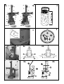
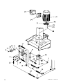
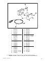
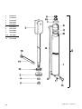
1 - DESCRIZIONE DELLA MACCHINA
SPV21 e SPV40 sono spaccalegna verticali trasportabili dotati di motorizzazione elettrica. In fig.1a e 1b sono illustrate le varie parti della
macchina.
1 - Lama
2 - Trave telescopica
3 - Leve del comando a due mani
4 - Maniglia di trasporto
5 - Piano di lavoro
6 - Leva di boccaggio del piano mobile (solo su modello SPV40)
7 - Motore elettrico
8 - Ruote per piccoli spostamenti
9 - Tappo di carico olio
10 - Serbatoio dell'olio
11 - ZONA DI LAVORO CONSENTITA E OBBLIGATORIA
8
D22001250 v.1 - UPD 191201
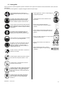
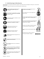
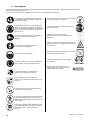
1.1 - Iconografia
Sulla macchina sono riportate segnalazioni grafiche normalizzate al fine di garantire la massima sicurezza relativamente a tutte le parti dello
spaccalegna.
Per limportanza di tali segnalazioni vi preghiamo di leggere attentamente quanto segue.
Leggere attentamente lintero libretto di uso e
manutenzione della macchina prima della messa in
funzione.
É vietato agganciare e sollevare lo spaccalegna per
la maniglia di spostamento.
Per evitare danni acustici causati da una lunga
esposizione delloperatore alle fasi lavorative,
alcune delle quali con livelli di rumore rilevanti, si
dovranno indossare apposite cuffie antirumore.
Lo spaccalegna deve essere utilizzato da una
sola persona.
Al fine di evitare schiacciamenti dei piedi durante le
normali operazione di carico e scarico dei ceppi di
legno, è obbligatorio indossare adeguate calzature
di protezione.
Pericolo: senso di direzione della lama.
Non toccare mai la lama o il braccio portante in
movimento.
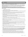
Per riparare le mani da schegge di legno o urti
contro la macchina è obbligatorio indossare
adeguati guanti a protezione di entrambe le mani.
Contro eventuali urti al capo è obbligatorio indossare un casco che lo ripari adeguatamente.
Per evitare urti al viso ed in particolare il lancio di
schegge verso gli occhi che possono prodursi
durante le operazione di rottura del ceppo, è
obbligatorio indossare una visiera protettiva per
lintera superficie del viso.
Pericolo di taglio e schiacciamento della mano: non
toccare mai le zone a rischio durante il movimento
della lama.
Pericolo: non tentare di sbloccare un ceppo incastrato nella lama usando le mani.
Pericolo: tensione elettrica come indicato da
targhetta.
Senso di rotazione del motore. In caso di
rotazione errata seguite le istruzioni riportate
nel capitolo 4.
É vietato rimuovere o manomettere le protezioni e i
dispositivi di sicurezza.
É vietato eseguire qualsiasi intervento di manutenzione sulla macchina quando questa è in moto.
É vietato fumare in prossimità della macchina o
comunque nellarea di lavoro.
É vietato sostare nel raggio di azione della macchina quando questa è in moto. Nessuna persona o
animale può sostare in un raggio di cinque metri
dalla macchina durante il normale funzionamento
della stessa.
É vietato scaricare lolio esausto nellambiente.
Lolio deve essere smaltito secondo le leggi in
vigore nel paese in cui viene effettuata tale
operazione.
D22001250 v.1 - UPD 191201
9
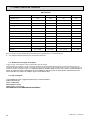
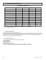
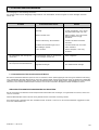
2 - CARATTERISTICHE TECNICHE
DATI TECNICI
SPV21 E
SPV21 T
SPV40 E
SPV40 T
Lunghezza (mm)
700
700
700
700
Larghezza (mm)
515
515
515
515
1046÷1556
1046÷1556
1046÷1556
1046÷1556
Peso (Kg)
96
96
108
108
Massima pressione di lavoro (bar)
220
200
220
200
Massima forza di spinta (tons.)
6
6
6
6
Lunghezza max. di taglio (mm)
540
540
1040
1040
10÷30
10÷30
10÷30
10÷30
Capacità serbatoio olio (lt.)
3,2
3,2
3,2
3,2
Capacità totale olio (lt.)
4,2
4,2
4,2
4,2
Alimentazione
230V 50Hz Monofase
400V 50Hz trif.
230V 50Hz Monofase
400V 50Hz trif.
Assorbimento
13,5A
6A
13,5A
6A
3CV - 2,2KW
4CV - 3KW
3CV - 2,2KW
4CV - 3KW
Altezza (mm)
Diametro del legno da rompere (cm)
Potenza
Rumore ≤ 79 dB (A) misurati all'altezza dell'orecchio dell'operatore in posizione di lavoro, a macchina operante.
•
Sono obbligatorie adeguate protezioni per le orecchie (cuffie antirumore).
2.1 - Dimensioni del legno da rompere
In figura 2 a pag. 2 sono indicate le misure massime dei tronchi da rompere.
Il diametro del legno è indicativo: un tronco di piccole dimensioni può risultare difficoltoso da rompere se contiene nodosità oppure se è
formato da fibra particolarmente robusta. Al contrario, se il legno ha fibre regolari non sarà difficile rompere tronchi il cui diametro supera le
dimensioni massime consigliate in figura 2. È importante evitare di insistere quando il tronco non si spacca al primo tentativo in
quanto la pompa può essere danneggiata dal surriscaldamento dell'olio dovuto al mantenimento della macchina sotto
sforzo massimo nel tentativo di rompere legno eccessivamente duro.
2.2 - Olii consigliati
Vi consigliamo di usare i seguenti tipi di olio per il cilindro idraulico:
SHELL TELLUS T22
ARAL VITAM GF22
BP ENERGOL HCP22
MOBIL DTE11 o equivalenti.
NON USATE OLII CON GRADAZIONI DIFFERENTI.
10
D22001250 v.1 - UPD 191201
3 - SICUREZZA
É estremamente importante leggere quanto riportato in questo capitolo. Esso contiene la descrizione dei possibili rischi
generati dalluso della macchina e le relative informazioni atte a consentire un uso corretto della stessa ed evitare danni
alle persone, agli animali e alle cose.
ATTENZIONE: gli spaccalegna BELL mod. SPV21 e SPV40 sono stati progettati e costruiti al solo scopo di rompere ceppi di legno le cui
dimensioni non siano diverse da quelle raccomandate in fig.2.
Ogni altro uso è da ritenersi improprio ed il costruttore non risponde in alcun modo di eventuali danni a persone, animali
od oggetti causati da un uso erroneo della macchina.
É obbligatorio che loperatore agisca soltanto dalla posizione indicata in fig.1 e che il comando di azionamento della macchina venga manovrato con entrambe le mani, senza ricorrere ad espedienti diversi e senza manomettere il comando ZHB.
In fase di lavoro non è consentita la presenza di persone ed animali ad una distanza inferiore ai 5 metri dalla macchina.
NON TENTARE DI MANOMETTERE LE PROTEZIONI DELLO SPACCALEGNA O DI LAVORARE SENZA DI ESSE.
IL MANCATO RISPETTO DI QUANTO RIPORTATO IN QUESTO CAPITOLO PUÒ CAUSARE GRAVI DANNI ALLE PERSONE E AGLI OGGETTI NONCHÉ ALLA MACCHINA STESSA.
3.1 - Regole generali di sicurezza
• La macchina deve essere usata da un solo operatore.
• Non si deve permettere luso dello spaccalegna a terzi se questi non ha letto il manuale di uso e manutenzione o se non è stato istruito
•
•
•
•
•
•
•
•
•
•
•
•
•
•
•
•
•
•
•
sulle regole da seguire per un corretto e sicuro uso.
L'uso della macchina è consentito solamente ai maggiorenni. L'uso dello spaccalegna da parte di apprendisti di età comunque non
inferiore a 16 anni deve avvenire sotto la supervisione di un maggiorenne abilitato all'uso.
Non si devono indossare indumenti larghi o sbottonati o comunque che possano rimanere impigliati nelle parti in movimento della macchina.
Non muovere o spostare lo spaccalegna mentre il motore è in movimento
Non si deve operare su un terreno in pendenza, accidentato o sdrucciolevole. Posizionate la macchina su un piano ben livellato e libero
da oggetti che possano impedire la piena libertà dazione e di lavoro per loperatore.
Controllate che i tronchi da spaccare siano privi di nodosità, chiodi, viti o fili di ferro che possono essere lanciati violentemente verso le
persone durante il taglio. Le estremità dei tronchi devono essere tagliate in squadro.
I rami devono essere tranciati a filo del tronco.
Non tentate di tagliare ceppi di dimensioni superiori a quelle indicate in fig.2: potrebbe essere pericoloso e si potrebbe danneggiare la
macchina.
Posizionate il tronco in modo che venga spaccato nella direzione delle fibre. Diversamente può risultare pericoloso e può compromettere
il funzionamento della macchina.
Non cercate di tagliare due tronchi contemporaneamente: uno potrebbe essere sbalzato via colpendovi.
Se il tronco tende a scivolare via dalla lama, ritrarre lo spingitronco o la lama e ruotare il tronco di 90°
Non caricate il tronco mentre la macchina è in funzione: potreste impigliarvi e rimanere feriti.
Tenete le dita lontano dalle fenditure e dalle crepe che si formano sul tronco: queste potrebbero chiudersi improvvisamente causando
gravi schiacciature o addirittura amputazioni.
Non forzate lo spaccalegna per più di 30 secondi, tenendo il cilindro in pressione o provando a rompere legna troppo dura. Trascorso
tale tempo, infatti, lolio sotto pressione si surriscalda e la macchina potrebbe danneggiarsi.
Non lasciate la macchina incustodita. Se dovete abbandonare il luogo di lavoro, togliete la fonte di alimentazione e fate attenzione a
qualsiasi possibile rischio di accensione accidentale.
Non usate mai lo spaccalegna sotto l'influenza di alcoolici, droghe, farmaci o se siete particolarmente stanchi. La lucidità è sostanziale
per la sicurezza ed una distrazione potrebbe causare incidenti anche gravi.
Non tentate di disincastrare i ceppi bloccati mentre la macchina è in moto: durante tale operazione la macchina deve essere spenta.
Non fatevi aiutare da terzi per disincastrare un ceppo bloccato.
Non usate la macchina in presenza di gas naturale, vapori di benzina o altri vapori infiammabili.
Verificate che limpianto elettrico che alimenterà la macchina sia idoneo. Dovranno essere controllate tensione, frequenza di rete e
potenza erogata (verificate la targhetta sulla macchina ed i dati nel presente manuale). Lo spaccalegna dovrà essere collegato ad un
impianto dotato di salvavita differenziale adatto e in rispetto alle normative e dovrà essere presente un adeguato impianto di messa a
terra.
Usate cavi di sezione pari a 2,5 mm2. Non lavorate con connessioni volanti e non adeguatamente isolate. I collegamenti devono essere
L'uso di prolunghe eccessivamente lunghe o di sezione inadeguata può provocare cadute di tensione che non permettono al motore di sviluppare tutta la sua potenza.
fatti con materiale protetto e adeguato per esterno.
•
•
•
•
Verificate sempre che la macchina e il cavo non vengano a contatto con acqua.
Onde evitare avviamenti accidentali alla connessione della macchina, verificate che linterruttore sia in posizione 0, spento.
Non tirate il cavo di alimentazione per spostare la macchina, non date strattoni al cavo stesso e tenetelo lontano da fonti di eccessivo
calore, olii, solventi e oggetti taglienti.
Non lasciate mai la macchina incustodita se collegata allimpianto elettrico. Quando la macchina non si usa deve essere sempre
disconnessa ed in particolare quando si deve eseguire qualsiasi intervento di manutenzione.
D22001250 v.1 - UPD 191201
11
4 - MESSA IN FUNZIONE
Non usate mai lo spaccalegna se non è in perfetta efficienza o se necessita di manutenzione. Prima dell'utilizzo verificate che tutti i dispositivi
di sicurezza (ZHB, pulsante di spegnimento sulle macchine elettriche) funzionino come previsto.
Prima di iniziare a lavorare, controllate il livello dellolio idraulico nel serbatoio e, se necessario, rabboccate usando lolio indicato a pag.10.
Il livello dellolio deve essere compreso fra le due tacche poste sullo stelo del tappo olio.
Prima di iniziare a lavorare accendete la macchina e lasciate riscaldare lolio per alcuni minuti.
Dopo 200 ore di uso dalla prima messa in funzione, pulite il filtro dellolio come indicato nel paragrafo 6.1.
Dopo aver collegato lalimentazione alla macchina con motore elettrico trifase, verificate il senso di rotazione del motore che deve corrispondere a quello della freccia posta sul fondello del motore stesso. Se il senso di rotazione non coincide, è necessario invertire due poli nella
spina.
Togliete la presa dallo spaccalegna quindi inserite un cacciavite con taglio a lama di dimensioni adeguate nella feritoia posta nel bocchettone
di connessione vicino al motore elettrico come indicato in figura 4.
Premete delicatamente e allo stesso tempo girate di 180° la ruota bianca. Con questa operazione si invertono fisicamente i poli sul motore
trifase. Verificate ora che il motore giri effettivamente nel senso corretto indicato dalla freccia.
I Non aprite mai la scatola dellinterruttore posta sul motore o la morsettiera.
In caso di necessità consultate il vostro elettricista di fiducia.
Se saltano i fusibili o le protezioni, significa che si sta sovraccaricando il motore oppure che limpianto elettrico non è adeguato: consultate il
vostro elettricista di fiducia.
4.1 - Illuminazione
Tutte le zone della macchina devono essere illuminate in modo da garantire la loro perfetta visibilità durante il lavoro, le operazioni di manutenzione e le regolazioni. Anche in caso di lavoro in esterni, è indispensabile che vi sia sufficiente luce per poter eseguire il lavoro in sicurezza. È vietato lavorare durante orari in cui la scarsità di luce può causare una cattiva visibilità della macchina e dei suoi componenti (alba,
crepuscolo, notte).
5 - USO
5.1 - Accensione e spegnimento dello spaccalegna
•
•
•
•
•
•
•
Verificate che l'interruttore/salvavita dell'impianto generale e l'interruttore della macchina siano spenti.
Collegate lo spaccalegna elettrico all'impianto di alimentazione inserendo l'apposita presa nella spina situata sul motore elettrico.
Prestate attenzione a non far passare il cavo di alimentazione sopra alla trave telescopica, nelle vicinanze della lama o comunque in un
posto in cui potrebbe subire danni o troncarsi.
Armate l'interruttore generale quindi accendete lo spaccalegna premendo l'interruttore nella zona verde.
La trave telescopica si porterà automaticamente in posizione di tutto aperto.
Usate lo spaccalegna come spiegato nel paragrafo 5.2.
Se vi assentate spegnete lo spaccalegna, premendo l'interruttore nella zona rossa (spento).
Terminato il lavoro, togliete alimentazione alla macchina mettendo in posizione "0" (spento) l'interruttore/differenziale dell'impianto generale
quindi estraete la spina dalla presa sulla macchina. Nel compiere tale operazione, non tirate mai il cavo ma prendete il corpo della presa e
toglietela.
5.2 - Uso dello spaccalegna
•
•
Posizionate il ceppo di legno sul piano di lavoro come indicato in fig.5, centrandolo sotto alla lama. É importante, per una buona sicurezza
nel lavoro che le due facce del tronco siano parallele fra loro e al piano.
Operando solamente dalla posizione consentita (fig.1), stringete il tronco con le leve del comando ZHB in modo da conficcare leggermente le griffe nella corteccia quindi abbassate le leve (fig.6a): la lama si azionerà conficcandosi nel tronco.
Nota: appena la lama inizia a spaccare il tronco allargate leggermente i bracci del comando ZHB (fig.6b) continuando a tenere
premute le leve verso il basso per evitare che le griffe si danneggino sotto sforzo.
•
•
Se il tronco di legno non dovesse rompersi velocemente, oppure se la lama si dovesse fermare, non mantenete la macchina sotto sforzo.
Così facendo, infatti, l'olio nel circuito idraulico si surriscalda molto velocemente danneggiando la pompa. É conveniente far tornare la
trave a riposo e riprovare ruotando il tronco.
Ripetete l'operazione con i pezzi ottenuti in modo da spaccare il ceppo in più parti.
Nota: Se lasciate una sola delle due leve la macchina si bloccherà nella posizione in cui si trova. Se lasciate entrambe le leve la trave
telescopica si porterà nella posizione di tutto aperto.
12
D22001250 v.1 - UPD 191201
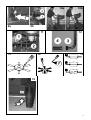
5.3 - Uso del piano di lavoro ruotabile (SPV 40)
Lo spaccalegna mod. SPV 40 è dotato di un piano di lavoro ruotabile che, aperto, consente di rompere tronchi lunghi fino a 104 cm.
Ecco come procedere per rompere un tronco lungo 104 cm.:
•
•
A: Aprite il piano ruotabile (2 in fig.7), posizionate il tronco (3 in fig.8) sul piano fisso (1) e procedete alla sua rottura come indicato nel
paragrafo 5.2.
poichè lo spaccalegna è dotato di lama a rapida apertura, il tronco dovrebbe rompersi completamente. Se il tronco non si rompesse,
lasciate le leve del comando ZHB: il tronco incastrato nella lama risalirà assieme alla trave.
B: Chiudete il piano ruotabile, BLOCCATELO CON LA LEVA (4), abbassate la protezione anticaduta per il tronco (5) e ripetete l'operazione: la lama si conficcherà ulteriormente nel legno, rompendolo, l'anello anticaduta tratterrà il tronco impedendogli di cadere.
I ATTENZIONE
NON LAVORATE CON IL PIANO DI LAVORO NON BLOCCATO DALLA RELATIVA LEVA: TALE OPERAZIONE PUÒ CAUSARE GRAVI
INCIDENTI ALL'OPERATORE E DANNI ALLA MACCHINA E RICORDATE DI ABBASSARE SEMPRE L'ANELLO ANTICADUTA PER IL
TRONCO.
5.4 - Regolazione della corsa della lama
Per risparmiare tempo è stato studiato un sistema che permette la regolazione della corsa della lama così da regolarla su tronchi corti
facendogli compiere la corsa strettamente necessaria. Una volta verificata la lunghezza massima dei tronchi da tagliare, procedete alla
regolazione come segue:
•
•
•
•
Azionate lo spaccalegna e portate la lama nella posizione desiderata quindi lasciate andare solamente una delle due leve di comando
della macchina in modo che la lama si fermi nella posizione che voi avete scelto.
Con l'altra mano svitate il pomello 1 in fig.9a.
Tirate l'asta (2 in fig.9b) verso l'alto fino al suo bloccaggio.
Riavvitate il pomello (1) serrando bene.
Ora lo spaccalegna si riposizionerà nel punto da voi regolato.
5.5 - Movimentazione dello spaccalegna
Per una movimentazione comoda e sicura fate uso dell'apposito maniglione posto nella parte alta della trave (fig.10a).
•
•
Puntate un piede sul basamento dello spaccalegna quindi tirando il maniglione, sbilanciate la macchina verso di voi in modo da poterla
spostare comodamente (fig.10b).
Per appoggiarla, rimettete un piede sul basamento e posatela delicatamente a terra.
D22001250 v.1 - UPD 191201
13
6 - MANUTENZIONE ORDINARIA
In questo capitolo vengono descritte le operazioni di manutenzione ordinaria, pertanto quelle effettuate dall'operatore, sugli spaccalegna
SPV21e SPV40 al fine di mantenerli sempre in perfetta efficienza e quindi affidabili per un uso continuativo e duraturo.
Ogni operazione di manutenzione ordinaria deve essere compiuta a macchina spenta e, nel caso di spaccalegna ad alimentazione elettrica,
con il cavo di alimentazione disconnesso.
Ogni altra operazione di manutenzione non specificamente contemplata in questo manuale deve essere effettuata da
personale specializzato in quanto si possono creare situazioni di pericolo sulle quali l'operatore non è preparato.
Ogni operazione di manutenzione straordinaria o sostituzione di parti di ricambio non effetuate da personale specializzato,
fanno immediatamente decadere la garanzia e sollevano il costruttore da qualsiasi responsabilità per danni a persone,
animali o cose.
6.1 - Pulizia del filtro dellolio
Ogni 200
300 ore di lavoro è necessario pulire accuratamente il filtro dellolio del sistema idraulico così da mantenerlo sempre in perfetta efficienza.
•
•
•
•
•
•
•
•
Togliete il carter posteriore di protezione della pompa asportando le sei viti che la bloccano.
Svitate il dado (1) in fig.11
Togliete la guarnizione (2) che trattiene il tubo usando un cacciavite a lama piatta ma non tagliente, premendo su tutta la sua circonferenza (fig.13) fino a farla uscire dal corpo del serbatoio. Quando la guarnizione sarà stata completamente sfilata, estraete il tubo di supporto
del gruppo filtro.
Tirando senza esercitare un eccessivo sforzo, per evitare di rovinare la guarnizione del filtro (3 in fig.12), staccate il filtro (4).
Lavate il filtro con benzina pulita e, se possibile, soffiatelo con aria compressa. Nel caso non si riuscisse a pulire adeguatamente il filtro,
sarà necessario sostituirlo con uno nuovo.
Rimontate il filtro sulla guarnizione.
Reinserite il filtro nella sua sede sul serbatoio avendo laccortezza di tenere il filtro stesso diretto verso destra.
Con un cacciavite a croce premete con forza moderata su tutta la circonferenza della guarnizione fino a farla penetrare nella lamiera
(fig.14). È estremamente importante che la lamiera entri nellincavo della guarnizione come indicato in fig.15; diversamente vi sarà
trafilamento di olio dal foro.
Nota: per facilitare loperazione di rimontaggio della guarnizione vi consigliamo di scaldarla con un asciugacapelli prima di reinserirla.
IATTENZIONE
NON USATE CACCIAVITI TAGLIENTI, CON LA PUNTA ACUMINATA O CUTTER PER TOGLIERE E RIMONTARE LA GUARNIZIONE IN
QUANTO POTREBBE DANNEGGIARSI.
Una volta reinserito il tubo, fissatelo serrando il dado relativo.
6.2 - Sostituzione dell'olio idraulico
Ogni 600 ore di lavoro è necessario sostituire l'olio esausto con altro olio nuovo del tipo riportato a pag.10.
Per sostituire l'olio procedete come segue.
•
•
•
•
Assicuratevi che la trave della macchina sia completamente rientrata (lama chiusa).
Mettete sotto al tappo di scarico olio situato nel retro della macchina (fig.16) una vaschetta di raccolta che possa contenere circa 5 litri di
olio.
Svitate il tappo di scarico con una chiave adeguata e lasciate scendere nella vaschetta tutto l'olio contenuto nel serbatoio.
Quando il serbatoio è completamente svuotato, pulite l'imbocco, la rondella di rame e il tappo di scarico con benzina, quindi riavvitate il
tappo di scarico a fondo ricordandovi di reinserire la rondella.
l serbatoio dell'olio contiene circa 4,2 litri di olio.
•
•
•
•
•
Sfilate il tappo dell'olio (fig.3) e riempite il serbatoio con olio adatto, versandone circa 3 litri
Accendete lo spaccalegna e mettete in funzione la trave telescopica facendogli compiere 1/3 della corsa completa.
Abbassate completamente la lama quindi aggiungete l'olio rimanente e fate compiere alla macchina due cicli completi per permettere la
fuoriuscita dell'aria dal circuito idraulico.
Verificate con l'astina di livello (fig.3) che vi sia la giusta quantità di olio.
Pulite l'imbocco del tappo dell'olio e reinserite il tappo.
IATTENZIONE:
NON GETTATE L'OLIO ESAUSTO FRA I RIFIUTI GENERICI!
L'OLIO ESAUSTO DEVE ESSERE SMALTITO SECONDO LE PRESCRIZIONI DI LEGGE IN VIGORE NEL PAESE DI UTILIZZO DELLA MACCHINA.
6.3 - Affilatura della lama
Dopo numerose ore di lavoro e comunque in caso di bisogno, affilate la lama dello spaccalegna usando una lima a denti fini e facendo
attenzione ad asportare anche eventuali bave o schiacciature del metallo.
14
D22001250 v.1 - UPD 191201
7 - INCONVENIENTI E RIMEDI
La seguente tabella riporta i possibili problemi che possono verificarsi durante l'uso dello spaccalegna ed i relativi rimedi consigliati.
Ogni intervento da parte di personale non specializzato fa decadere immediatamente la garanzia della macchina e solleva il costruttore da
qualsiasi responsabilità per danni causati alle persone, agli animali e alle cose.
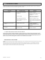
Problema
Il tronco non si spacca
Probabile causa
Rimedio
Pressione idraulica troppo bassa
Contattare il rivenditore
Perdita di olio
Individuare la perdita usando un pezzo
di carta o di legno. Contattare il
rivenditore.
La lama non taglia
Affilare la lama; controllare bave o
tacche, limare se necessario
Errato posizionamento del tronco
Sistemare correttamente il tronco
Il tronco è di dimensioni più grandi di
quelle consentite
Cercare di tagliarne una piccola parte o
ridurre con altri mezzi la dimensione del
tronco.
Lo stelo avanza a scatti o con forti
vibrazioni
Presenza di aria nel circuito
Controllare il livello dell'olio e, se
necessario, aggiungerne.
Se il problema persiste contattate il
rivenditore.
Perdita di olio dai raccordi, dalla pompa
o dal cilindro
Raccordi lenti
Stringere i raccordi
Guarnizioni usurate
Contattare il rivenditore
7.1 - Riarmo della protezione termica del motore elettrico
Durante il lavoro con macchine alimentate elettricamente, nel caso di un sovraccarico, uno sbalzo molto forte di tensione oppure un guasto
accidentale all'impianto elettrico, interverrà un dispositivo di protezione applicato al motore e integrato nell'interruttore generale. in caso di
intervento della protezione, prima di chiamare il centro di assistenza autorizzato, attendete alcuni minuti quindi provate a riarmare l'interruttore
generale. Se non si ripresenta il problema, potete usare la macchina tranquillamente. Se invece la protezione dovesse saltare ancora, non
insistete nel tentativo di farla rimanere agganciata e contattate il centro di assistenza tecnica autorizzata.
DEMOLIZIONE DELLO SPACCALEGNA
La demolizione della macchina deve essere eseguita rispettando tutte le norme di sicurezza atte ad evitare danni alle persone, alle cose e agli
animali.
Tutte le parti della macchina devono essere rottamate e smaltite secondo le leggi vigenti nel luogo in cui viene effettuata la demolizione.
Particolare attenzione è da porre allo smaltimento dell'olio idraulico che non deve essere assolutamente gettato nell'ambiente in quanto
altamente inquinante ma deve essere smaltito secondo le prescrizioni di legge.
D22001250 v.1 - UPD 191201
15
GARANZIA
La ditta BELL S.r.l., denominata qui di seguito come BELL, garantisce al compratore di ogni nuovo prodotto originale BELL, acquistato da un
rivenditore autorizzato BELL, che tale prodotto è esente da difetti di materiale e manodopera per un periodo di 360 giorni (12 mesi) dalla data
dellacquisto originale o dalla data del primo noleggio.
Le parti di ricambio installate sul prodotto coperto da questa garanzia, sono garantite per 90 giorni (3 mesi) dalla data di sostituzione o
riparazione.
Tali parti devono essere fornite gratuitamente allutilizzatore dal rivenditore o distributore BELL durante le ore lavorative regolari.
BELL si riserva il diritto di ispezionare ogni prodotto o parte sostituita come difettosa. Le parti sostituite devono quindi essere conservate e
tenute a disposizione per 12 mesi.
È espressamente inteso che la BELL non ha obblighi di fornire manodopera o di accettare spese di trasporto.
BELL non si assumerà alcuna responsabilità per danni, difetti o costi derivanti da riparazioni e/o modifiche di un prodotto BELL, effettuati da
qualsiasi persona che non sia un tecnico autorizzato BELL.
Questa garanzia non sarà applicata ai componenti commerciali coperti da loro propria garanzia, quali motori a scoppio, diesel, ecc...
Non sono coperte da garanzia macchine o loro parti deteriorate da:
1) Uso scorretto o improprio, negligenza, abuso o incidente.
2) Mancanza di ragionevole o necessaria manutenzione come prescritto in questo manuale (Sostituzione di olio idraulico, olio motore, olio per
moltiplicatore consumati o esausti, lama non affilata, ecc...)
3) Luso di parti o accessori non costruiti, forniti o approvati da BELL.
La BELL non presta ulteriori espresse o sottintese garanzie, eccetto quelle qui contenute.
Ogni prolungamento del periodo di garanzia o estensione della stessa non verranno riconosciuti come validi e quindi applicati dalla BELL.
( Nessun rappresentante o rivenditore è autorizzato ad assumere altre responsabilità riguardo ai prodotti BELL.
La durata delle garanzie implicite riconosciute dalla legge, incluse le garanzie commerciali e convenienze per particolari scopi sono
limitate nella durata alla validità e durata della espressa garanzia qui sotto concesse.)
In nessun caso la BELL riconoscerà perdite di profitto, dirette o indirette, speciali o conseguenti a eventuali danni.
Per rendere convalidare la garanzia, il venditore deve completare e spedire di ritorno entro dieci (10) giorni dalla data di vendita o dalla data di
concessione in affitto, la cartolina di registrazione della garanzia, fornita con ciascuna unità venduta.
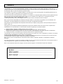
In caso di richiesta di ricambi o interventi di riparazione, sono indispensabili le seguenti informazioni:
MODELLO........................................................................................................
NUMERO DI SERIE .........................................................................................
DATA DI ACQUISTO ........................................................................................
16
D22001250 v.1 - UPD 191201
INTRODUCTION
BELL® log splitters have been designed and manufactured in compliance with the most recent European safety regulations with particular
reference to the EN609 and UNI60204 standards.
The ZHB control systems have been designed and engineered so that the operator is forced to work in the safety area without any
possibility of inserting hands or arms in dangerous areas.
Before transporting, installing or operating the machine, read all parts of this manual, paying particular attention to the specific safety
regulations.
Operators who are unable to understand any of the languages in which this manual is written are responsible for asking the retailer to
provide a manual in their own language.
The operator must also train any other person authorised to use the machine.
Failure to comply in any way with these instructions, improper use of the machine, extraordinary maintenance operations
not carried out by skilled, authorised personnel, removal of data plates or markings of any type, removal or tampering with
the guards and safety mechanisms of the machine or any other action not expressly authorised that may impair the active
and passive safety systems of the machine shall relieve the manufacturer of all and any liability and may result in serious
injury and damage.
If the machine is tampered with in any way by unauthorised personnel, the guarantee is automatically null and void. This manual is an integral
part of the machine and must accompany it even in the case of transfer of ownership.
1 - DESCRIPTION OF THE MACHINE
The SPV 21 and SPV 40 vertical, transportable logsplitters are equipped with their own electric motor. The various parts of the machines are
shown in fig. 1a and 1b.
1 - Wedge
2 - Telescopic mast
3 - ZHB control levers
4 - Carrying handle
5 - Work surface
6 - Locking lever of the work surface (only on SPV40 model)
7 - Electric motor
8 - Wheels for minor movements
9 - Oil plug
10 - Oil tank
11 - PERMITTED AND MANDATORY WORK AREA
D22001250 v.1 - UPD 191201
17
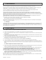
1.1 - Symbols used
Standard graphic symbols are used on all machines in order to ensure complete safety of all parts of the log splitter.
As these symbols are very important, read the information below attentively.
it is obligatory to read the machines use and
maintenance manual in full before using the
machine.
in normal conditions of use, our machines may
expose the operator daily to noise levels lower
than or equal to 85 dB(a). it is therefore obligatory
to wear ear defenders.
it is obligatory to wear safety footwear at all times
to provide protection against the risk of logs
accidentally falling on feet.
it is obligatory at all times to wear gloves which
protect the hands against chips and splinters
which may be produced during work.
it is obligatory at all times to wear a helmet which
protects the hands against chips and splinters
which may be produced during work.
it is obligatory at all times to wear goggles or a
visor which protects the hands against chips and
splinters which may be produced during work.
it is forbidden to remove or tamper with the
protection devices and safety devices.
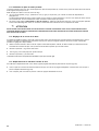
It is forbidden to hook or lift the log splitter by the
carrying handle.
The log splitter must be used by one person alone.
Warning: direction of rotation of the wedge.
Never touch the wedge or the supporting arm when in
movement.
Danger of cutting or crushing of the hand: never touch
hazardous areas while the wedge is moving.
Warning: never remove a log trapped in the wedge
with your hands.
Warning: voltage as indicated on the rating
plate
Direction of rotation of the motor. If the motor
runs in the wrong direction, follow the
instructions given in chapter 4.
it is forbidden to carry out any maintenance work
or to renew parts on the machine when it is
running.
it is forbidden to smoke near the machine and in
the work area.
it is forbidden to stand in the range of action of the
machine. apart from the operator, no other person
or animal may be present within a radius of 5
metres from the machine.
Dumping of used oil in the environment is forbidden.
The oil must be disposed of according to current
legislation in the country where this operation is
carried out.
18
D22001250 v.1 - UPD 191201
2 - TECHNICAL DATA
TECHNICAL DATA
SPV21 E
SPV21 T
SPV40 E
SPV40 T
Lenght (mm)
700
700
700
700
Widht (mm)
515
515
515
515
Height (mm)
1046÷1556
1046÷1556
1046÷1556
1046÷1556
Weight (kg)
96
96
108
108
220
200
220
200
Max. force (tons.)
6
6
6
6
Log capacity (mm)
540
540
1040
1040
10÷30
10÷30
10÷30
10÷30
Hydraulic oil tank capacity (lt.)
3,2
3,2
3,2
3,2
Hydraulic oil total capacity (lt.)
4,2
4,2
4,2
4,2
230V 50Hz Single-ph.
400V 50Hz 3-phase
230V 50Hz Single-ph.
400V 50Hz 3-phase
13.5A
6A
13.5A
6A
3Hp - 2.2KW
4Hp - 3KW
3Hp - 2.2KW
4Hp - 3KW
Max. pressure working (bar)
Diameter of the log to be split (cm)
Supply
Absorption
Power
Noise ≤ 79 dB(A) measured at the height of the operators ear in the working position with the log splitter in operation
•
The ears must be suitably protected (ear defenders).
2.1 - Size of the logs to be split
Figure 2 on page 2 shows the maximum log sizes that can be split.
The diameter of the log is indicative: a small log can be difficult to split if it has knots or a particularly tough fibre. On the other hand, if the
wood has regular fibres it is not difficult to split logs with diameters greater than the maximum shown in Figure 2. It is important not to
insist when the log does not split on the first attempt, as the pump may be damaged by the overheating of the oil when the
machine is made to work under the maximum stress in the attempt to split excessively hard wood.
2.2 - Recommended oils
We recommend use of the following oils for the hydraulic cylinder:
SHELL TELLUS T22
ARAL VITAM GF22
SP ENERGOL HCP22
MOBIL DTE11 or equivalent
DO NOT USE OTHER GRADE OILS.
D22001250 v.1 - UPD 191201
19
3 - SAFETY
The information given in the chapter is extremely important for safety purposes. It describes possible hazards tied to use
of the machine and instructions for correct use of this to avoid injury or damage.
WARNING: The log splitters mod. SPV21and SPV40 have been designed and manufactured to split logs of the sizes recommended on page 5
only.
Use of the machine for any other purpose shall be considered improper and the manufacturer shall not be liable for any
injuries or damage to be ascribed to improper use of the machine.
The operator must work in the position shown in figg.1a and 1b only and operate the machine drive control with both hands without using
other makeshift systems and without tampering with the ZHB control.
When the machine is working, persons and animals must be kept at a distance of at least 5 meters from the machine.
NEVER ATTEMPT TO TAMPER WITH THE PROTECTIONS OF THE LOG SPLITTER OR TO OPERATE THE MACHINE WITHOUT THESE.
FAILURE TO COMPLY WITH THE INSTRUCTIONS GIVEN IN THIS CHAPTER MAY RESULT IN SERIOUS INJURY OR DAMAGE TO
PERSONS, THINGS AND TO THE MACHINE.
3.1 - General safety regulations
•
•
•
•
•
•
•
•
•
•
•
•
•
•
•
•
•
•
•
•
•
•
•
•
•
20
The machine must always be used by one operator only.
Nobody must be allowed to use the log splitter unless they have read the instruction manual and have been instructed in the regulations
to follow for correct and safe use.
The machine must be used by adults only. Use of the log splitter by apprentices of not less than 16 years of age must be supervised by
an adult authorised to use the machine.
Never wear loose, unbuttoned clothing which may become trapped in moving parts.
Do not move the log splitter while the motor is running.
Do not work on sloping or slippery ground. position the machine in a flat area free from objects which may impede the freedom of
movement of the operator.
Check that the logs to be split are free from nails or wire, which may fly up or damage the machine. the ends of the logs must be cut
square. branches must be cut off flush with the trunk.
Never try to split logs larger than those indicated in fig. 2. This could be dangerous and may damage the machine.
Break wood in the direction of the grain. do not place wood across the log splitter and leave it in that position for splitting; it may be
dangerous and may seriously damage the machine.
Never attempt to cut two logs at once; one may fly up and hit you.
If the log moves away from the blade, retract the ram or the blade and turn the log through 90°.
Do not attempt to load the log in the log splitter while the ram is in motion. you could get trapped and injured.
Keep your hands well away from any splits and cracks which open in the log; these may close suddenly and crush or amputate your
fingers.
Do not force the log splitter for more than 30 seconds by keeping the cylinder under pressure at the end of its stroke, or by persisting
when a log does not split or gets stuck on the blade. Oil under pressure overheats very rapidly, damaging the pump.
Never leave the machine unattended while it is running. If you leave the machine, even for a short time, remove the power supply or any
possible cause of accidental start-up.
The log splitter must never be used by an operator who is under the influence of alcohol, drugs, medicines, or who is tired. A clear mind
is essential for safety.
Never try to release a jammed log while the machine is running. The machine must be switched off during this operation.
Never request the assistance of another person to help you remove a jammed log.
Do not use machines with electric motor if natural gas, petrol fumes or other inflammable vapours are present.
Check that the electric circuit is adequately protected and that it corresponds with the power, voltage and frequency of the motor; check
that there is a ground connection, and a regulation differential switch upstream.
Use cables with a section of 2.5 mm2. Avoid use of free and inadequately insulated connections. Connections must be made with
protected material suitable for outdoor use. Using cable extensions which are excessively long or inadequately
sectioned may cause voltage drops which prevent the motor from reaching full power.
Make sure that the machine and the cable never come in contact with water.
To prevent accidental start-up, ensure that the switch is off before plugging in the power cable.
Treat the power cable with care. do not attempt to move the machine by pulling the cable. do not yank the cable to unplug it; keep the
cable away from excessive heat, oil and sharp objects.
Never leave the machine unattended with the power supply on. also disconnect the power cable when not in use, when carrying out
maintenance work, when changing attachment or moving the machine.
D22001250 v.1 - UPD 191201
4 - OPERATING THE MACHINE FOR THE FIRST TIME
Never use the log splitter if it is not in perfect order or if it needs servicing. Before starting work, check correct functioning of all the safety
devices (ZHB, switch-off button on electric machines).
Before starting work, check the level of the hydraulic oil in the tank and top up if necessary with one of the oils indicated on page 19.
The level of the oil must be between the two notches on the rod of the oil plug.
Before starting work, switch on the log splitter and let the oil warm up for a few minutes.
After 200 hours of use, clean the oil filter as explained in paragraph 6.1 before starting the machine.
If the motor does not run in the correct direction, invert two of the phases in the socket. Remove the plug from the log splitter. Insert a slotted
screwdriver with a suitably sized wedge in the slot located in the connection inlet close to the electric motor as shown in figure 4. Exerting a
slight pressure, turn the white wheel by 180°. This operation physically inverts the poles on the three-phase motor.
Check that the motor runs in the correct direction as indicated by the arrow.
I Never open the box containing the switch, or open the terminal block on the motor. if it is necessary to do so, have
these operations carried out by your electrician.
If the fuses blow or the protection valve trips, this means that you are overloading the motor or the electrical installation is not correctly rated.
Consult your electrician.
4.1 - Lighting
Lighting must be provided in the entire work area of the log splitter to ensure perfect visibility when operating the machine and during
maintenance and adjustments. Even when working outdoors, there must be sufficient light to work safely. Working at times when insufficient
light may result in poor visibility of the machine and its components (dawn, dusk, night) is forbidden.
5 - USE
5.1 - Switching on/off of the log splitter
•
•
•
•
•
•
•
Make sure that the switch/cutout of the general power system and the switch of the machine are OFF.
Connect the electric log splitter to the power system inserting the plug in the socket on the electric motor.
Never pass the power cable over the telescopic mast, close to the wedge or anywhere where it may be damaged or cut.
Set the main on/off switch and then press the switch in the green area to start the log splitter.
The telescopic mast will move automatically to the fully open position.
Use the log splitter as explained in paragraph 5.2.
Never leave the log splitter unattended without first of all pressing the switch in the red area (off).
On completing the work, switch off the log splitter by turning the switch/differential of the general power system to the 0 position (off)
and then remove the plug from the socket on the machine. Never yank the plug using the cable. Grasp the body of the plug and pull it
firmly.
5.2 - How to use log splitter
•
•
Place the log on the work surface as shown in fig.5 making sure it is centered under the wedge. The two faces of the log must be
parallel to each other and to the work surface to guarantee safe operation.
Working in the mandatory position only (fig.1), grasp the log with the levers of the ZHB control so that the jaws penetrate slightly into the
bark and then lower the levers (fig.6a); the wedge will start to cut into the log.
Note: As soon as the wedge starts to split the log, widen the arms of the ZHB control slightly (fig.6b) continuing to press
the levers down so that the force applied does not damage the jaws.
•
•
If the log does not split quickly or if the wedge stops, do not keep the machine under force. Then hydraulic oil overheats very quickly
with damage to the pump. It is advisable to return the mast to the idle position and to make another attempt after rotating the log.
Repeat the operation with the pieces obtained so as to split the log into several parts.
Note: If you let go of even just one of the levers, the machine will stop in the position reached. If you let go of both levers, the telescopic
mast will move to the fully open position.
D22001250 v.1 - UPD 191201
21
5.3 - How to use the movable table
The SPV 40 logsplitter is equipped with a movable table, which makes it possible to split logs up to 104 cm of lenght.
In order to split a log of 104 cm, proceed as follows:
•
•
A- : Open the movable table (2 in Fig.7), put the log (3 in Fig.8) on the fixed table (1) and then split it as pointed out in par. 5.2.
As the logsplitter is equipped with a fast-opening wedge, the log should split completely. If it doesnt, release the ZHB levers: the log
jammed in the wedge will go up together with the beam
B-: Close the movable table, BLOCK IT WITH THE LEVER (4), let down the log protection against falling (5) and split again: the wedge
will stick deeper into the log and will split it. The protection ring will prevent the log from falling down.
I
WARNING
DO NOT WORK WITHOUT BLOCKING THE WORK SURFACE WITH THE PERTINENT LEVER, OTHERWISE THE USER COULD BE WOUNDED
AND THE MACHINE DAMAGED, AND DO NOT FORGET TO LET THE PROTECTION RING DOWN.
5.4 - How to adjust blade stroke
To save time, a system has been designed that makes it possible to adjust wedge travel so that this can be set for short logs. In this way, the
wedge travels for the distance required only. After checking the length of the longest logs to be split, regulate wedge travel as follows:
•
•
•
•
Start the log splitter and bring the wedge to the position required. Release one of machine control levers so that the wedge stops in the
selected position.
Back off knob 1 in fig.9a with the other hand.
Pull the rod (2 in fig.9b) up until it locks in place.
Draw up the knob (1) again making sure it is tight.
The log splitter will now reposition at the point selected.
5.5 - How to transport the log splitter
Use the carrying handle on the top part of the mast (fig. 10a) for safe, trouble-free transport of the log splitter.
•
•
22
Rest one foot on the base of the log splitter. Pull the handle, tilting the machine towards you to facilitate transport (fig. 10b).
To rest the machine on the ground, put one foot on the base and lower the machine carefully.
D22001250 v.1 - UPD 191201
6 - ROUTINE MAINTENANCE
This chapter describes routine maintenance, i.e. operations carried out by the operator, on the SPV21 and SPV40 log splitters to keep this in
perfect working order and therefore reliable for continuous, long-term use.
All routine maintenance operations must be carried out with the machine off and in the case of log splitters with electric motor with the
power cable disconnected.
Any other maintenance operation not specifically envisaged in this manual must be carried out by authorised personnel
only in that hazardous situations may arise for which the operator is not prepared.
In the case in which extraordinary maintenance or part replacement operations are not carried out by authorised
personnel, the guarantee shall be immediately null and void and the manufacturer shall be relieved of any responsibility for
injury to persons or animals or damage.
6.1 - How to clean the oil filter
To keep the machine in perfect working order, the oil filter of the hydraulic system must be throughly cleaned every 200
300 hours of operation.
•
•
•
•
•
•
•
Take the back covering which protects the pump off by removing the six screws that block it.
Unscrew the nut (1) in fig.11
Remove the gasket (2) which holds the tube with a flat screwdriver by pressing on its periphery (fig.13) until it is out of the tank body.
When the gasket is completely free, extract the tube which supports the filter group.
Pull the filter (4) off the tube. Be careful not to damage the filter gasket (3 in fig.12).
Wash the filter with petrol and, if possible, blow it with compressed air. If the cleaning does not succed, the filter must be replaced with
a new one.
Re-insert the filter in its housing in the oil tank. During this operation, keep the filter leaning on the right.
Press on the periphery of the gasket with a cross-screwdriver until it has got into the plate (fig.14). Carefully operate according to
fig. 15, otherwise oil may leak.
N.B. In order to re-assemble the gasket easier, we recommend to warm it with a hair dryer before operating.
WARNING:
NEVER USE SHARF SCREWDRIVERS OR CUTTERS TO REMOVE AND RE-ASSEMBLE THE GASKET, OTHERWISE IT COULD BE
DAMAGED.
Once you have re-inserted the tube, fix it with the pertinent nut.
6.2 - How to change the hydraulic oil
The spent oil must be replaced with new oil of the type indicated on page 19 every 600 hours of operation. To change the oil, proceed as
follows.
•
•
•
•
Make sure that the mast of the machine is fully retracted (wedge closed).
Place a receptacle able to hold around 5 litres of oil under the oil drainage plug located to the rear of the machine (fig.16).
Unscrew the drainage plug with a suitable wrench and let all the oil in the tank drain into the receptacle.
Once the tank is empty, clean the inlet, the copper washer and the drainage plug with petrol and then replace the drainage plug, drawing
this up tightly. Remember to insert the washer.
The oil tank holds around 4.2 litres of oil.
•
•
•
•
•
Remove the oil plug (fig.3) and fill the tank with the correct oil, pouring in around 3 litres.
Switch on the log splitter and activate the telescopic mast for 1/3 of its complete travel.
Lower the wedge completely and add the remaining oil.
Run the machine for two complete cycles to bleed any air from the hydraulic circuit.
Use the oil rod (fig.3) to check the right quantity of oil.
Clean the inlet of the oil plug and replace the plug.
I
WARNING:
NEVER MIX OIL WITH GENERAL WASTE!
USED OIL MUST BE DISPOSED OF ACCORDING TO CURRENT REGULATIONS IN THE COUNTRY WHERE THE MACHINE IS USED.
6.3 - Sharpening the wedge
After long periods of operation and when required, sharpen the wedge of the log splitter using a fine-toothed file and taking care to remove
any burrs or crushed parts of the metal.
D22001250 v.1 - UPD 191201
23
7- TROUBLESHOOTING
Problems that may arise when using the log splitter and recommended remedies are given in the table below.
In the case of operations carried out by unauthorised personnel, the guarantee will be immediately null and void and the manufacturer will be
relieved of any responsibility for injury to persons and animals and damage.
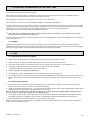
Problem
Log fails to split
Probable cause
Corrective action
Hydraulicpressure too low
Contact your dealer
Oil leack
Locate the leack using a piece of card
or wood.
Contact your dealer
Wedge do not cut
Sharped the wedge, check for burrs
or nicks, file if necessary
Incorrect positioning of the log
Change the position of the log in
relation to the wedge
Log exceeds permitted dimensions
Try to cut a small part or use other
means to reduce the size of the log
Air in the circuit
Check oil level.Top up if necessary
If problem remain contact your dealer
Rod advances jerkily or with strong
vibrations
Unions not properly tight
Tighten unions
Oil leak from the unions, pump or
cylinder
Seals worn
Contact your dealer
7.1 - Resetting of the thermal cut-out of the electric motor
In the case of machines with electric motor, a protection device applied to the motor and integrated in the main on/off switch is tripped in the
case of overloads, sudden increases in voltage or accidental faults in the electrical system. In this case, before calling your authorised
service centre, wait a few minutes and then try to reset the main on/off switch. If the problem does not re-occur, the log splitter can be used
normally. If the cut-out is tripped again, do not try to reset it and contact your ahthorised service centre.
DISMANTLING OF THE LOG SPLITTER
The log splitter must be dismantled complying with all safety regulations, designed to prevent injury and damage.
All parts of the log splitter must be scrapped and disposed of according to current legislation where the machine is dismantled.
Pay particular attention when eliminating hydraulic oil which must not be disposed of in the environment in that it is highly pollutant and must
be disposed of according to legal prescriptions.
24
D22001250 v.1 - UPD 191201
GUARANTEE
The company BELL, referred to hereinafter as BELL, guarantees to the purchaser of every new BELL original product, purchased from a
BELL authorized dealer, that the product shall remain free from any defects in materials or workmanship for a period of 360 days (12
months) from the original date of purchase or the date of first hire.
Spare parts installed on the product covered by this guarantee are guaranteed for 90 days (3 months) from the date of their repair or
renewal.
Such parts must be supplied free of charge to the user by a BELL dealer or distributor during normal working hours.
BELL reserves the right to inspect any product or part which has been substituted as defective. Substituted parts must therefore be kept
available for 12 months.
It is expressly understood that BELL shall be under no obligation to provide labour or accept transport expenses.
BELL shall accept no responsibility for any damage, defect or costs deriving from repairs and/or modifications of a BELL product, effected
by any person other than an authorized BELL representative.
This guarantee does not apply to commercial components covered by their own guarantee, such as internal combustion engines, diesel
engines, etc..
This guarantee covers only defects arising during proper use of the machine. BELL shall accept no responsibility whatsoever if BELL
components break while under guarantee for reasons such as:
1)
2)
Misuse, negligence, improper handling, abuse or accident.
Failure to carry out reasonable or necessary maintenance as prescribed in this manual (renewal of worn components such as slides,
hydraulic oil, engine oil, gearbox oil; blade not sharpened, etc.)
3) The use of parts or accessories not manufactured, supplied or approved by BELL.
BELL does not provide further explicit or implied guarantees, other than those set forth herein. No representative or dealer is authorized to
assume other responsibilities with regard to BELL products.
The duration of the implicit guarantees recognized by the law, including the commercial guarantees and conventions for particular purposes
are limited in duration to the validity and duration of the explicit guarantee granted below.
BELL shall upon no account act as guarantor for loss of profit, whether direct or indirect, specific or deriving from any damage.
To validate this guarantee, the seller must complete and return within ten (10) days of the date of sale, or the date of hire, the guarantee
registration card supplied with each unit sold.
If you require spare parts or repair work it will be useful the followins informations:
MODEL .............................................................................................................
SERIAL NUMBER ...........................................................................................
DATE OF PURCHASE .....................................................................................
D22001250 v.1 - UPD 191201
25
EINLEITUNG
Die Holzspalter BELL sind in Entsprechung der letzten europäischen Sicherheitsnormen, insbesondere EN609 und EN60204, geplant und
gebaut.
Sie sind mit ZHB-Steuersystemen ausgestattet, die zum Schutz des Bedieners in Sicherheitsbereichen angeordnet sind.
Das Handbuch aufmerksam lesen, eine genaue Kenntnis der darin enthaltenen Sicherheitsvorschriften ist unabdingbar, um sämtliche Arbeiten
für den innerbetrieblichen Transport sowie zur Installation und Inbetriebsetzung der Maschine in voller Sicherheit auszuführen.
Wenn der Benützer die Sprache der vorliegenden Handbücher nicht kennt, muß er bei seinem Händler die Übersetzung in die eigene Sprache
anfordern.
Der Benützer muß mit dem Maschinenbetrieb beauftragten Arbeitskräfte zweckgerecht schulen.
Der Hersteller haftet nicht für Folgeschäden an Personen oder Sachen, die durch Mißachtung dieser Anleitungen,
unsachgemäßen Gebrauch der Maschine, Entfernung von Etiketten und Kennschildern, Entfernung oder Verstellung von
Schutz- und Sicherheitsvorrichtungen und jedes andere sicherheitswidrige Handeln bewirkt sind.
Änderungen an der Maschine dürfen ausschließlich von hierzu befugtem Personal ausgeführt werden.
Das vorliegende Handbuch ist als integrierender Teil der Maschine zu betrachten, auf der es stets griffbereit aufzubewahren ist.
1 - MASCHINENBESCHREIBUNG
SPV 21 und SPV 40 sind verfahrbare Vertikal-Holzspalter mit elektrischem Motor. Im Bild 1a und 1b sind die verschiedenen
Maschinenkomponenten gezeigt.
1 - Messer
2 - Teleskopbalken
3 - ZHB-Bedienhebel
4 - Transportgriff
5 - Holzauflage
6 - Arbeittischesklemmhebel (nur für das Modell SPV40)
7 - E-Motor
8 - Räder für kurze Verfahrungsstrecken
9 - Öleinfüllstutzen
10 - Ölbehälter
11 - VORSCHRIFTLICHER UND VERBINDLICHER ARBEITSBEREICH
26
D22001250 v.1 - UPD 191201
1.1 - Aufschlüsselung der Warnhinweise
Auf der Maschine sind normgerechte Warnzeichen angebracht, damit sämtliche Teile des Holzspalters vorsichtig und in voller Sicherheit
bedient werden.
Bitte lesen Sie mit größter Aufmerksamkeit die Auschlüsselung dieser Gefahrenhinweise.
Vor der Inbetriebsetzung der Maschine sind die
Betriebs- und Wartungsanleitungen genau
durchzulesen.
Zur Vermeidung von Gehörschäden ist bei langen
und lärmreichen Arbeitszyklen ein entsprechender
Ohrschutz zu tragen.
Die Füße sind vor fallenden Holzklötzen durch feste
Schuhe abzuschützen.
Die Hände sind durch geeignete Handschuhe vor
wegspringenden Holzsplittern zu schützen.
Schutzhelm gegen Verletzungen durch
wegspringende Holzsplitter tragen
Schutzbrillen oder Visier zum Schutz vor
wegspringenden Holzsplittern tragen.
Verwenden Sie den Bewegungsgriff nicht zum
Hochziehen des Holzspalters.
Der Holzspalter muss von einer einzigen Person
bedient werden.
Warnung: Drehrichtung des Messers. Nie das Messer
noch den Tragarm, wenn er in Bewegung steht,
berühren.
Achtung auf Schnittwunden oder Zerquetschungen: die
Hände während der Messerbewegung von den
Gefahrbereichen weghalten.
Warnung: einen am Messer verklemmten Holzklotz
nie mit den Händen zu entfernen versuchen.
Warnung: Elektrische Spannung gemäß Schildangabe
Motordrehrichtung: bei falscher Drehung die
Anleitungen des Kapitels 4 befolgen.
Schutz- und Sicherheitseinrichtungen dürfen nie
verstellt werden.
Wartungs- oder Reparaturarbeiten nie bei in Betrieb
stehender Maschine ausführen.
In der Nähe der Maschine und im Arbeitsbereich
nicht rauchen.
Es dürfen sich keine Personen im Arbeitsbereich
der Maschine aufhalten. Umstehende Personen
oder Tiere müssen sich mindestens 5 m entfernt
von der Maschine befinden.
Das Altöl muß nach den örtlich geltenden Gesetzen
entsorgt werden und darf nie in die Umwelt
abfließen.
D22001250 v.1 - UPD 191201
27
2 - TECHNISCHE EIGENSCHAFTEN
TECHNISCHE EIGENSCHAFTEN
SPV21 E
SPV21 T
SPV40 E
SPV40 T
Länge (mm)
700
700
700
700
Breite (mm)
515
515
515
515
Höhe (mm)
1046÷1556
1046÷1556
1046÷1556
1046÷1556
Gewicht (Kg)
96
96
108
108
Max. Betriebsdruck (bar)
220
200
220
200
Max. Schubkraft (tons.)
6
6
6
6
Max. Schnittlänge (mm)
540
540
1040
1040
Klotzdurchmesser (cm)
10÷30
10÷30
10÷30
10÷30
Inhalt Ölbehälter (Liter)
3,2
3,2
3,2
3,2
Fassungsvermögen Öl insgesamt (lt.)
4,2
4,2
4,2
4,2
230V 50Hz Einphasig
400V 50Hz dreiph.
230V 50Hz Einphasig
400V 50Hz dreiph.
13,5A
6A
13,5A
6A
3PS - 2,2KW
4PS - 3KW
3PS - 2,2KW
4PS - 3KW
Versorgung
Stromaufnahme
Leistung
Der Bediener ist während des Betriebs unserer Maschine einem Geräuschpegel von 79 dB(A) ausgesetzt.
•
Er muß daher Gehörschutz tragen.
2.1 - Maße des Spaltklotzes
In Abb. 2 Seite 2 werden die max. Holzklotzmaße angegeben.
Der Spalklotzdurchmesser ist beispielhaft angegeben. Ein kleiner Holzklotz kann schwer zu spalten sein, wenn er astig ist. Im Gegenteil wird
es bei weichen Holz nicht schwierig sein, Holzklötze mit größerem Durchmesser zu spalten. ACHTUNG : wenn der Holzklotz nicht sofort
gespalten wird, ist es sehr wichtig, den Spaltvorgang abzubrechen, sonst ist eine rasche Überhitzung des unter Druck
stehenden Öls mit Folgenschäden an der Pumpe möglich.
2.2 - Empfohlene Ölsorten
Für den Hydrozylinder werden die folgenden Ölsorten empfohlen:
SHELL TELLUS T22
ARAL VITAM GF22
BP ENERGOL HCP22
MOBIL DTE11 oder gleichwertige
ÖLE MIT ANDEREM VISKOSITÄTSGRAD DÜRFEN NICHT VERWENDET WERDEN.
28
D22001250 v.1 - UPD 191201
3 - SICHERHEIT
Lesen Sie dieses Kapitel mit der größten Aufmerksamkeit, eine genaue Kenntnis der darin beschriebenen Gefahrsituationen während des Maschinenbetriebs und der Anweisungen für den ordnungsgemäßen Gebrauch ist unabdingbar
zur Vermeidung von Personen-, Tier- und Sachschäden.
ACHTUNG: Die Holzspalter BELL Mod. SPV 21 und SPV 40 dienen ausschließlich zum Spalten von Holzklötzen, deren Ausmaße den Angaben
auf Seite 5 entsprechen müssen.
Jeder andere Einsatz gilt als unsachgemäß und der Hersteller haftet für keinerlei Folgeschäden an Personen, Tieren oder
Gegenständen, die durch den betriebsfremden Einsatz der Maschine bewirkt sind.
Der Anwender muß bei der Maschinenbedienung im vorgeschriebenen Arbeitsbereich (Abb.1) stehen, wobei er zur Betätigung der
Steuervorrichtung beide Hände verwenden muß, er darf keinesfalls zu anderen Systemen greifen und ebenso die ZHB-Steuerung nicht
verstellen. Personen oder Tiere dürfen sich während des Maschinenbetriebs nicht näher als 5 m vom Holzspalter aufhalten.
DER HOLZSPALTER DARF AUSSCHLIESSLICH MIT ORDNUNGSGEMÄSS INSTALLIERTEN SCHUTZVORRICHTUNGEN BETRIEBEN
WERDEN. DIE MISSACHTUNG DER ANWEISUNGEN DIESES KAPITELS KANN SCHWERE FOLGESCHÄDEN AN PERSONEN,
GEGENSTÄNDEN ODER AN DER MASCHINE SELBST MIT SICH BRINGEN.
3.1 Allgemeine Sicherheitsvorschriften
•
•
•
•
•
•
•
•
•
•
•
•
•
•
•
•
•
•
•
•
•
Es darf nur eine Person auf der Maschine arbeiten und Baumstämme aufladen.
Niemand darf den Holzspalter verwenden, ohne zuvor die Gebrauchsanleitungen gelesen zu haben oder über die Vorschriften für den
ordnungsgemässen und sicheren Maschinengebrauch belehrt worden zu sein.
Die Bedienungsperson muß mindestens 18 Jahre alt sein. Auszubildende mit einem Mindestalter von 16 Jahren dürfen nur unter Aufsicht
an der Maschine arbeiten.
Nie aufgeknöpfte oder lockere Kleidung tragen, weil sie sich in den Bewegungsteilen verfangen könnte.
Den Holzspalter bei laufendem Motor nicht bewegen.
Nicht auf abfallendem oder rutschigem Boden arbeiten. Die Maschine ist auf einem ebenen Boden zu positionieren. Der umliegende
Bewegungsraum darf nicht durch Gegenstände verstellt sein.
Überprüfen, ob von den zu spaltenden Stämmen alle Eisendrähte entfernt worden sind, welche während des Spaltens wegspringen
oder die Maschine beschädigen könnten. Die äußeren Enden der Stämme müssen winkelig geschnitten werden. Die Äste müssen
vollkommen abgeschnitten werden.
Es dürfen nie Holzklötze gespaltet werden, deren Ausmaße über die in Abb.2 abgegrenzten Werte hinausgehen: dies könnte
Verletzungen und Maschinenschäden bewirken.
Das Holz muß der Faser entlang gespaltet werden. Den Holzklotz nie quer auf den HOLZSPALTER LEGEN UND IN dieser Position
SPALTEN. Dies könnte VERLETZUNGEN MASCHINENSCHÄDEN MIT SICH BRINGEN.
Auf keinen Fall zwei Stämme gleichzeitig schneiden! Einer könnte wegspringen und den Bediener treffen.
WENN DER Holzklotz VOM MESSER ABGLEITET, DEN Stammandrücker zurückziehen und den Holzklotz um 90° drehen.
Den Stamm nicht bei IN BETRIEB STEHENDEM Holzspalter ODER laUFENDEM MESSER AUF DEN HOLZSPALTER LADEN,
verletzUNGSGEFAHR!
Nicht in die sich während des Spaltens auf der Holzrinde bildenden Schlitze und Risse greifen, weil sich diese plötzlich wieder
schliessen und die Finger zerdrücken oder amputieren könnten.
Den Holzspalter nicht mehr als 30 Sekunden zwangsläufig betreiben, indem man den Stammandrücker am Endanschlag angedrückt hält
oder wenn man den Schnitt eines spaltunwilligen oder im Messer verklemmten Holzklotzes erzwingen will, dies würde eine rasche
Überhitztung des unter Druck stehenden Öls mit Folgeschäden an der Pumpe mit sich bringen.
Die laufende bzw. auch nur angeschlossene Maschine nie unbewacht lassen. Bei momentanem Verlassen der Maschine die Stromversorgung unterbrechen und jede zufällige Startmöglichkeit ausschliessen.
Den Holzspalter keinesfalls unter Einfluß von Alkohol, Rauschgift und Medikamenten oder bei Müdigkeit verwenden. Nur mit klarer
Geistesverfassung kann sicher gearbeitet werden.
Eingeklemmtes Holz nicht bei laufendem Motor vom Spaltkeil entfernen. Maschine immer erst ausschalten und dann das eingeklemmte
Holzstück entfernen.
Um eingeklemmtes Holz zu entfernen lassen Sie Ihnen durch dritte Personen nicht helfen.
DIE MASCHINE DARF NICHT IM EX-BEREICH (NATÜRLICHES GAS, BENZINDÄMPFE ODER ANDERE ENTFLAMMBARE DÄMPFE)
VERWENDET WERDEN.
Überprüfen, ob der Stromkreis wirksam geschützt und auf die elektrischen Eigenschaften des Motors ausgelegt ist: Leistung-SpannungFrequenz (vgl. hierzu die Angaben des Maschinenschildes); Erdschluß und normgerechter Spannungswandler in Vorschaltung sind
unabdingbar.
Kabeln mit einem Querschnitt von 2,5 mm2 verwenden. Nie mit freiliegenden und mangelhaft isolierten Anschlüssen arbeiten. Die
Verwenden Sie keine zu
langen Verlängerungskabel und keine ungeeigneten Querschnitte, weil diese einen Spannungsabfall
verursachen können und der Motor könnte seine ganze Leistung nicht entwickeln.
Anschlüsse sind stets mit abgeschütztem und für Außenverlegung geeignetem Material auszuführen.
•
•
•
•
Die Maschine und das Kabel dürfen nie mit Wasser in Berührung kommen.
VOR ANSCHLUß DES NETZKABELS SICHERSTELLEN, daß SICH der HAUPTSCHALTER IN OFF-STELLUNG BEFINDET, DAMIT DIE
MASCHINE NICHT VERSEHENTLICH STARTET.
Stromzufuhrkabel nicht misshandeln. Zum Verschieben der Maschine nicht am Kabel ziehen. Kabel nicht aus der Steckdose herausreissen und von Hitzequellen, von Öl und von schneidenden Gegenständen fernhalten.
Die EINGESCHALTETE ODER IN BETRIEB STEHENDE Maschine nie unbewacht lassen. NETZKABEL AUCH BEI nichtVERWENDUNG, SOWIE
VOR Wartungsarbeiten, WECHSELN DES AnschlussES ODER VERSTELLEN DER Maschine ABSTECKEN.
D22001250 v.1 - UPD 191201
29
4 - INBETRIEBSETZUNG
Die Maschine DARF nie VERWENDET WERDEN, WENN SIE SICH IN BETRIEBSWIDRIGEM ZUSTAND BEFINDET ODER WARTUNGSBEDÜRFTIG
IST. Machen Sie sich vor dem Gebrauch der Maschine mit den Bedienungs-und Sichereitselementen des Holzspalters und mit deren Funktion.
Vor dem Inbetriebsetzen den Hydrauliköstand im Tank überprüfen und ggf. mit der auf Seite 28 empfohlenen Ölsorte nachfüllen; das Öl muß
zwischen die Min. und Max.-Markierung des Ölmeßstabes reichen.
VOR ARBEITSBEGINN DIE Anlage starten und DAS Öl einige Minuten lang warmlaufen lassen.
Nach den ersten 200 Betriebsstunden den Ölfilter gemäß den Anleitungen auf Kap. 6.1 reinigen.
Bei vorschriftswidriger Drehrichtung sind die zwei Pole des Stromsteckers untereinander auszutauschen. Nach Stromanschluß des Motors
ist die Drehrichtung zu überprüfen: sie muß der Pfeilanzeige am Motor entsprechen. Hierzu die Strombuchse vom Holzspalter abnehmen und
einen passenden Schraubenzieher in den Schlitz des Anschlußstutzens neben dem E-Motor (Abb. 4) stecken.
Behutsam drücken und gleichzeitig das weiße Rad um 180° drehen, wodurch die Pole des Wechselstrommotors untereinander versetzt
werden. An dieser Stelle überprüfen, ob der Motor nun in Pfeilrichtung dreht.
I Das Schaltergehäuse und der Klemmenkasten am Motor dürfen nur im Bedarfsfall und nur von einem Elektriker
geöffnet werden.
Überbeanspruchung des Motors oder eine vorschriftswidrig ausgelegte elektriche Ausrüstung bewirken das Durchbrennen der
Schmelzsicherungen oder Ansprechen des Sicherheitsventils: in diesem Fall den Fachelektriker zu Hilfe ziehen.
4.1 - Beleuchtung
Sämtliche Maschinenteile müssen während des Betriebs und der Ausführung der Arbeiten zur Wartung und Einstellung arbeitsgerecht
beleuchtet sein. In den Tagesstunden, die keine klare Sicht der Maschine und ihrer Komponenten zulassen (bei Morgen- oder
Abenddämmerung und in der Nacht), ist der Betrieb nicht gestattet.
5 - EINSATZ DES HOLZSPALTERS
•
•
•
•
•
•
•
•
•
5.1 - Zu- und Abschalten des Holzspalters
Sicherstellen, daß der IS-Schalter der Anlage und der Maschinenschalter ausgeschaltet sind.
Den elektrischen Holzspalter an den Netzteil anschließen; hierzu den Stecker des elektrischen Motors in die dementsprechende
Strombuchse einführen.
Bei der Verlegung des Stromversorgungskabels darauf achten, daß es nicht über den Teleskopbalken oder nahe der Säge geführt wird;
ebenso sind Stellen zu vermeiden, an denen Beschädigungs- oder Durchreißgefahr besteht.
Den Hauptschalter rüsten und den Holzspalter durch Betätigen des Schalters im grünen Feld zuschalten. Der Teleskopbalken wird
automatisch in die Stellung der vollständigen Öffnung gebracht.
Den Holzspalter gemäß den Anleitungen des Kapitels 5.2 verwenden.
Bevor Sie den Holzspalter verlassen, betätigen Sie den Schalter im roten Feld (off).
Nach Abschluß der Arbeit ist der Holzspalter spannungslos zu setzen, indem man den Fehlerstrom-Schutz der Anlage auf 0 stellt
(ausgeschaltet), hiernach ist der Stromstecker aus seiner Buchse (auf der Maschine) zu ziehen. Hierbei darf nie am Kabel gezogen
werden.
5.2 - Verwendung des Holzspalters
Den Holzklotz gemäß Abb.5 auf die Auflageplatte legen und unter der Säge zentrieren. Ein sicheres Arbeiten ist nur dann gewährleistet,
wenn die beiden Flachseiten des Holzklotzes parallel zueinander und zur Platte ausgerichtet sind.
Den Holzklotz, im vorgeschriebenen Arbeitsbreich stehend (Abb.1), mit den Hebeln der ZHB-Steuerung so einspannen, daß die Klauen in
die Rinde einstechen, sodann die Hebeln niederschieben (Abb. 6a); an dieser Stelle wird die Säge zum Schnitt gestartet.
Merke: Sobald das Messer den Holzklotz spaltet, sind die Arme der ZHB-Steuerung (Abb. 6b) etwas zu spreizen, wobei der
Druck auf die Hebeln fortzusetzen ist, damit die Klauen durch die Krafteinwirkung nicht beschädigt werden.
•
•
Bei Spaltschwierigkeiten oder Anhalten der Säge die Maschine nicht zwangläufig betreiben. Hierdurch würde sich das Öl im
Hydraulikkreis sehr schnell erhitzen, was Folgeschäden der Pumpe mit sich bringt. Es empfiehlt sich in diesem Fall, den Balken in
Ruhestellung zu bringen und einen neuen Schnittversuch nach Umdrehen des Holzklotzes vorzunehmen.
Den Arbeitsgang mit den geschnittenen Stücken wiederholen, um den Holzklotz in mehrere Teile zu schneiden.
Merke: Wird auch nur einer der beiden Hebeln losgelassen, stoppt die Maschine unverzüglich. Werden beide Hebeln losgelassen, wird der
Balken in Öffnungsstellung gebracht.
30
D22001250 v.1 - UPD 191201
5.3 - Gebrauch des drehbaren Arbeitstisches
Der Holzspalter SPV 40 ist mit einem drehbaren Arbeitstisch ausgestattet, der das Spalten von bis zu 104 cm langen Holzklötzen ermöglicht.
Zum Spalten eines 104 cm langen Holzklotzes ist folgendermaßen vorzugehen:
•
•
A: Den drehebaren Tisch (2, Abb.7) öffnen, den Holzklotz (3, Abb.8) auf den feststehenden Tisch (1) stellen und ihn gemäß den
Anleitungen im Paragraph 5.2 spalten. Da der Holzspalter mit einem Schnellöffnungsmesser ausgestattet ist, sollte der Klotz komplett
gespaltet werden. Wenn aber der Klotz nicht komplett gespaltet wird, sind die Hebel der ZHB-Steuerung loszulassen: der im Messer
verklemmte Holzklotz steigt zusammen mit dem Träger auf
B: Den drehebaren Tisch schließen und MIT DEM HEBEL BLOCKIEREN, den Fallschutzbügel senken (5) und den Eingriff wiederholen.
Das Messer tritt tiefer in den Holzklotz ein. Der Bügel vermeidet, daß der Klotz beim Spalten auf den Boden fällt.
I
ACHTUNG
ES IST IMMER DARAUF ZU ACHTEN, DAß DER ARBEITSTISCH BEI DER ARBEIT DURCH DEN SPEZIELLEN BOLZEN BLOCKIERT IST, DA
ANDERNFALLS SCHWERE VERLETZUNGEN DES BEDIENERS UND EINE BESCHÄDIGUNG DER MASCHINE MÖGLICH SIND. AUßERDEM,
VERGESSEN SIE NICHT, DEN FALLSCHUTZBÜGEL ZU SENKEN.
5.4 - Einstellung des Messerhubes
Dank eines besonderen Systems kann zur Zeitersparnis der für kurze Holzklötze benötigte Messerhub eingestellt werden.
Nach Messung der max. Länge der Schnittklötze ist die Einstellung folgendermaßen vorzunehmen:
•
•
•
•
Den Holzspalter in Betrieb setzen und die Säge schnittgerecht positionieren; sonach einen der beiden Bedienhebeln der Maschine
loslassen, so daß die Säge in der eingestellten Position anhält.
Mit der anderen Hand den Knauf 1 Abb. 9a abdrehen.
Den Stab (2, Abb. 9b) bis zu seiner Arretierung nach oben ziehen.
Den Knauf (1) wieder andrehen und festspannen.
Der Holzspalter positioniert sich nun in der vorgegebenen Stellung.
5.5 - Handling des Holzspalters
Für ein sicheres und bequemes Transportieren sollte man sich des Griffes am oberen Teil des Balkens bedienen (Abb.10a).
•
Stemmen Sie einen Fuß auf den Unterbau des Holzspalters und ziehen Sie am Griff, damit die Maschine gegen Sie gekippt steht und
problemlos transportiert werden kann (Abb.10b).
•
Zur erneuten Positionierung stellen Sie einen Fuß auf den Unterbau und lassen Sie die Maschine behutsam auf den Boden niederkippen.
D22001250 v.1 - UPD 191201
31
6 - REGELMÄSSIGE WARTUNG
In diesem Kapitel werden sämtliche Arbeiten zur regelmäßigen Wartung des Holzspaltern SPV21 und SPV40, die vom Bediener auszuführen
sind, beschrieben. Wir empfehlen die skrupelhafte Ausführung dieser Wartungsarbeiten, damit die Maschine die bewährten Eigenschaften an
Leistungsfähigkeit, Zuverlässigkeit und langer Nutzdauer erbringen kann.
Vor sämtlichen Arbeiten zur Instandhaltung ist die Maschine abzustellen; im Falle eines Holzspalters mit elektrischem Antrieb ist das Netzkabel
abzuschließen.
Wartungsarbeiten, die in diesem Handbuch nicht ausdrücklich beschrieben sind, müssen von Fachpersonal ausgeführt
werden, da Gefahrensituationen entstehen können, auf die der Bediener nicht vorbereitet ist.
Anfallende Wartungsarbeiten oder Austausch von Ersatzteilen dürfen ausschließlich von Fachpersonal ausgeführt werden.
Der Hersteller haftet nicht für Folgeschäden an Personen, Tieren oder Gegenständen, die durch die Nichtbeachtung dieser
Regel bewirkt sind.
6.1 - Ölfilterreinigung
Jede 300
200 Arbeitsstunden muß der Ölfilter gereinigt werden.
•
•
•
•
•
•
•
•
Das hintere Pumpenschutzgehäuse abnehmen. Dafür sind die 6 entsprechenden Schrauben abzuschrauben.
Die Mutter abschrauben (Abb.11)
Die Filterdichtung aus dem Tank abnehmen. Verwenden Sie dafür einen Schraubenzieher mit unscharfer Klinge und drücken Sie auf die
ganze Kreislinie (Abb.13) bis die Dichtung komplett aus dem Tank ausgezogen worden ist. Dann, das Filterhalterrohr ausziehen.
Den Filter abziehen.
Den Filter mit sauberem Benzin reinigen und, wenn möglich, mit Druckluft blasen. Falls die Reinigung nicht erfolgt, muß der Filter mit einem
neuen getauscht werden.
Den Filter auf die Dichtung wieder montieren
Den Filter auf den Tank wieder einsetzen. Achten Sie darauf, daß der Filter nach rechts geschwenkt bleibt.
Mit einem Kreuzschraubenzieher auf die ganze Dichtungskreislinie drücken bis sie ins Blech eingesteckt wird. Wenn die Dichtung nicht
ins Blech genau wie auf Abb.15 eingesteckt wird, kann Öl herausfließen.
Anmerkung: wir schlagen vor, die Dichtung vor der Wiederzusammensetzung mit einem Haartrockener zu wärmen.
I
ACHTUNG:
VERWENDEN SIE NIEMALS SCHRAUBENZIEHER MIT SCHARFER KLINGE, DA DIE DICHTUNG DADURCH BESCHÄDIGT WERDEN KÖNNTE.
Nachdem das Rohr wieder eingesteckt worden ist, ist die entsprechende Mutter zu schließen.
6.2 - Wechsel des Hydrauliköls
Das Altöl ist alle 600 Betriebsstunden durch ein frisches der auf Seite 28 empfohlenen Ölsorte auszutauschen.
Für den Ölwechsel ist folgendermaßen vorzugehen:
•
•
•
•
Sich vergewissern, daß der Balken der Maschine vollständig eingezogen ist (Messer geschlossen)
Unter den Ölablaß auf der Rückseite der Maschine eine Sammelwanne stellen (Abb.16), die ein Fassungsvermögen von ca. 5 Lt. Öl hat.
Die Ablaßschraube mit einem passenden Schlüssel abdrehen und das gesamte Öl aus dem Behälter ausfließen lassen.
Nach vollständiger Entleerung des Behälters die Öffnung, die Kupferscheibe und die Ablaßschraube mit Benzin säubern, hiernach die
Ablaßschraube wieder fest andrehen und nicht vergessen, die Kupferscheibe einzusetzen.
Der Inhalt des Ölbehälters ist ca. 4,2 Lt.
•
•
•
•
•
Die Verschlußschraube abdrehen (Abb.3) und den Behälter mit 3 kg der vorgeschriebenen Ölsorte füllen.
Den Holzspalter anschalten und den Teleskopbalken in Betrieb setzen und hierbei 1/3 des vollständigen Hubes ausführen lassen.
Das Messer ganz absenken und das restliche Öl hinzufügen. Die Maschine Betriebszyklen lang betreiben, um den Hydraulikkreis zu
entlüften.
Mithilfe des Ölmeßstabes (Abb.3) den vorschriftsmäßigen Ölstand überprüfen.
Die Öffnung der Verschußschraube reinigen und hiernach den Verschluß wieder andrehen.
I
ACHTUNG:
DAS ALTÖL NICHT AN ÖFFENTLICHEN MÜLLSTELLEN WEGWERFEN, SONDERN NACH ÖRTLICH GELTENDER NORM ENTSORGEN!
6.3 - Schleifen des Messers
Nach längerem Betrieb oder auf jeden Fall bei Stumpfwerden, ist das Messer des Holzspalters mit einer feinen Feile zu schleifen. Hierbei sind
auch etwaige Grate oder eingedrückte Stellen abzuschleifen.
32
D22001250 v.1 - UPD 191201
7 - STÖRUNGEN UND DEREN BEHEBUNG
In der nachstehenden Tabelle werden sämtliche Betriebsstörungen, die während der Verwendung des Holzspalters auftreten können, sowie
die Arbeitsgänge zu ihrer Behebung beschrieben.
Der Hersteller haftet nicht für Mängelrügen infolge Personen- oder Sachschäden, die durch Eingriffe von seiten unbefugten Personals
bewirkt sind.
Problem
Der Stamm spaltet sich nicht
Anzunehmender Grund
Abhilfe
Hydraulischer Druck zu niedrig
Den Wiederverkäufer befragen
Ölleckage
Leckage herausfinden, unter Verwendung eines Stücks Papier oder Holz
Messer schneidet nicht
Messer schleifen, Grat- oder Kerbenbildung kontrollieren und ggf.
abschleifen.
Falsche Positionierung des Holzklotzes
Holzklotz und Messer zueinander
ausrichten
Die Maße des Holzklotzes liegen nicht in
den zulässigen Grenzen
Zurechtschneiden oder auf andere
Weise reduzieren
Luft im Kreislauf
Ölstand überprüfen, wenn nötig
nachfüllen
Die Kolbenstange läuft ruckartig oder
vibriert stark
Die hydraulischen Rohre für den Anschluß
an den Schlepper kreuzen sich
Rohre richtigstellen
Ölleckagen bei den Anschlusstellen,
der Pumpe oder beim Stammandrücker
Lockere Anschlüsse
Anschlüsse anziehen
abgenützte Dichtungen
Den Wiederverkäufer befragen.
7.1 - Rückstellen des Thermoschutzes des E-Motors
Bei elektrisch betriebenen Maschinen spricht im Falle von Überstrom, starken Spannungsprüngen oder Störung der elektrischen Ausrüstung
ein im Hauptschalter integrierter Motorschutz an. Nach der Auslösung dieses Schutzes einige Minuten warten und sodann den Hauptschalter
rückstellen. Wurde das Problem hierdurch gelöst, kann die Maschine wieder in Betrieb gesetzt werden. Sollte dagegen der Schutz nochmals
ansprechen, keine weiteren Rückstellversuche vornehmen und mit einer technischen Vertrags-Servicestelle Rücksprache nehmen.
VERSCHROTTUNG UND ENTSORGUNG DES HOLZSPALTERS
Bei der Verschrottung der Maschine sind die entsprechenden Sicherheitsnormen zu befolgen, um Folgeschäden an Personen, Sachen und
Tieren zu vermeiden.
Sämtliche Maschinenteile müssen nach den örtlich geltenden Normen verschrottet und entsorgt werden.
Die Entsorgung des Hydrauliköls stets nach Gesetzesvorschrift vornehmen, es darf nie an den normalen Müllstellen weggeworfen werden,
da es sehr umweltschädlich ist.
D22001250 v.1 - UPD 191201
33
GARANTIE
Die Firma BELL COMPANY, nachstehend BELL genannt, garantiert dem Erwerber jeder neuen, bei einem von BELL autorisierten Verkäufer,
gekauften BELL-Originalvorrichtung für eine Zeitspanne von 360 Tagen (12 Monaten) ab dem Tag des Erwerbs oder der ersten Vermietung,
daß die Maschinen keine Material- oder Bearbeitungsfehler haben. Für die Ersatzteile, die auf dem durch diese Garantie gedeckten
Holzspalter installiert sind, ist die Garantie auf 90 Tage (drei Monate) ab Ersatz- oder Reparatursdatum dieser Teile beschränkt.
Der Ersatz oder die, in von dieser Garantie gedeckten Vorrichtung eingebauten Ersatzteile werden 90 Tage lang ab Ersatz oder Reparatur
garantiert.
Diese Teile müssen dem Endverbraucher sowie dem von BELL autorisierten Verkäufer in den normalen Arbeitsstunden kostenlos geliefert
werden. BELL behält sich das Recht vor, eventuelle, aufgrund von Material- oder Bearbeitungsfehlern reklamierte Vorrichtungen oder Teile zu
überprüfen. Die ausgewechselten Teile sollen zur Verfügung für 12 Monate behalten werden.
Es versteht sich von selbst, daß BELL nicht dazu verpflichtet ist, Arbeitskräfte zu liefern oder für Transportkosten aufzukommen.
BELL haftet nicht für eventuelle Schäden, Fehler oder Kosten infolge von Reparaturen und/oder Änderungen an BELL-Vorrichtungen, die
nicht von einem von Fa. BELL autorisierten Vertreter ausgeführt worden sind z. B. Explosionsmotoren, Dieselmotoren.
Diese Garantie gilt nicht für Verkaufsartikel, die schon eine eigene Garantie haben, wie Motoren, Hydraulikpumpen, Getriebe und Schläuche,
ect.
Diese Garantie deckt nur bei normalem Betrieb entstandene Defekte. BELL nimmt keinerlei Verantwortung auf sich, wenn die BELL-Vorichtungen während der Garantiezeit aufgrund folgender Fehler nicht funktionieren:
1)
2)
Falsche Maschinenbedienung, Nachlässigkeit, unsachgemässer Maschinengebrauch, Mißbrauch oder Unfall.
Mangel an sinnvoller bzw. erforderlicher Wartung gemäss Gebrauchanweisung (Ersatz von Teilen, wie abgenützte Gleitführungen,
stumpfe Schneide, Hydrauliköl, Motoröl, Öl für Übersetzungsgetriebe)
3) Einsatz von Teilen oder Zubehör, die nicht von der Fa. BELL produziert, geliefert oder zugelassen sind.
Die Fa. BELL gewährt keine anderen als die ausdrücklich in diesem Schreiben enthaltenen Garantien. Kein Vertreter oder Verkäufer ist dazu
autorisiert, andere Garantien für die BELL-Vorrichtungen zu leisten. Die Dauer der gesetzmässigen Garantie, inbegriffen Garantie für
Verkäuflichkeit und Eignung für einen bestimmten Zweck, beschränkt sich auf die mit diesem Schreiben gewährte Garantiedauer. BELL haftet
auf keinen Fal für direkte oder indirekte, spezielle oder durch eventuelle Schäden verursachte Gewinnverluste.
Zur Gültigkeitserklärung dieser Garantie muß der Verkäufer den jeder Vorrichtung beiliegenden Garantieschein ausfüllen und ihn innerhalb
von zehn (10) Tagen ab Verkaufsdatum oder ab Datum der ersten Vermietung zurückstellen.
Bitte tragen Sie folgende Informationen ein, sie werden Ihrem Verkäufer bei der Bestellung von Ersatzteilen oder für den Kundendienst
nützlich sein.
MODELL ..........................................................................................................
SERIENNUMMER............................................................................................
ANKAUFSDATUM ...........................................................................................
34
D22001250 v.1 - UPD 191201
INTRODUCTION
Les machines fendeuses de bois BELL ont été étudiées et fabriquées conformément aux normes européennes les plus récentes sur la
sécurité, et en particulier aux normes EN 609 et EN 60204.
Les dispositifs de commande ZHB ont été étudiés dans le but dobliger lopérateur à manoeuvrer uniquement à partir des zones permises,
excluant ainsi toute introduction possible des membres dans les zones dangereuses.
Avant de déplacer, installer et rendre la machine opérative, lire attentivement ce manuel car il contient des règles importantes permettant de
travailler en toute sécurité.
Si lopérateur ne comprend aucune des langues de ce manuel, il doit demander au revendeur la traduction de ce dernier dans sa propre
langue.
Lopérateur doit aussi instruire toutes les personnes étant autorisées à utiliser la machine.
Le non respect des règles, un usage impropre de la machine, tout entretien extraordinaire non effectué par du personnel
spécialisé agréé, lenlèvement des étiquettes et des marquages de tout type, lenlèvement ou la modification des
protections et des dispositifs de sécurité ou toute autre action invalidant les dispositifs de sécurité actifs ou passifs de la
machine non expressément autorisée, font déchoir toute responsabilité du constructeur et peuvent entraîner de graves
lésions corporelles et provoquer des dommages matériels.
La modification de la machine par du personnel non agréé fait automatiquement déchoir la garantie.
Ce manuel fait partie intégrante de la machine et doit toujours laccompagner, même en cas de changement de propriétaire.
1 - DESCRIPTION DE LA MACHINE
SPV21 et SPV40 sont des machines à fendre le bois verticales, transportables, équipées dun moteur électrique. Les fig. 1a et 1b montrent
les différentes parties de la machine.
1 - Lame
2 - Poutre télescopique
3 - Levier de commande ZHB
4 - Poignée de transport
5 - Plan de travail
6 - Levier de blocage du plan de travail (seulement pour le modéle SPV40)
7 - Moteur électrique
8 - Roues pour petits déplacements
9 - Bouchon approvisionnement huile
10 - Réservoir dhuile
11 - ZONE DE TRAVAIL PERMISE ET OBLIGATOIRE
D22001250 v.1 - UPD 191201
35
1.1 - Iconographie
Des signalisations graphiques normalisées sont appliquées sur la machine dans le but de garantir le maximum de sécurité de toutes les
parties de la machine à fendre le bois.
En raison de limportance de ces signalisations, nous vous prions de lire attentivement ce qui suit:
Il est obligatoire de lire entièrement ce manuel de
mode demploi et dentretien avant la première mise
en route de la machine.
Il est obligatoire de porter un casque anti-bruit afin
déviter les dommages acoustiques provoqués par
une longue exposition de lopérateur aux phases de
travail, et ce car certaines delles ont un niveau de
bruit très élevé.
Le port de chaussures de sécurité qui protègent
contre la chute éventuelle de bûches, est
obligatoire.
Le port de gants qui protègent contre les
échardes de bois est obligatoire.
Le port du casque est obligatoire.
Le port de lunettes ou dune visière est obligatoire
pour se protéger contre les échardes de bois.
Il est interdit daccrocher ou de soulever la fendeuse
de bois par la poignée de transport.
La fendeuse de bois ne doit être utilisée que par
une seule personne.
Danger, sens de direction de la lame
Ne jamais toucher la lame ni le bras portant en
mouvement.
Danger de coupure ou décrasement de la main: ne
jamais toucher les zones à risque lorsque la lame est
en mouvement.
Danger: ne pas tenter de débloquer avec les mains
une bûche coincée dans la lame.
Danger: tension électrique (comme indiquée
sur la plaque)
Sens de rotation du moteur. En cas de
rotation dans le sens contraire, suivre les
indications données au chap. 4.
Il est interdit denlever ou de manipuler les
protections et les dispositifs de sécurité.
Il est interdit dexécuter toute intervention
dentretien ou de réparation lorsque la machine est
en marche.
Il est interdit de fumer à côté de la machine et de
toute façon sur le lieu de travail.
Il est interdit de stationner dans le rayon daction de
la machine. A part lopérateur aucune personne ou
animal ne peut stationner dans un périmètre de 5 m
de la machine.
Il est interdit de vidanger lhuile usée dans la nature.
Lhuile doit être éliminée conformément aux lois en
vigueur dans le pays où cette opération est
effectuée.
36
D22001250 v.1 - UPD 191201
2 - CARACTERISTIQUES TECHNIQUES
DONNEES TECHNIQUES
SPV21 E
SPV21 T
SPV40 E
SPV40 T
Longueur (mm)
700
700
700
700
Largeur (mm)
515
515
515
515
Hauteur (mm)
1046÷1556
1046÷1556
1046÷1556
1046÷1556
96
96
108
108
220
200
220
200
6
6
6
6
Longueur maxi. de coupe (mm)
540
540
1040
1040
Diamètre du bois à fendre (cm)
10÷30
10÷30
10÷30
10÷30
Contenance du réservoir à l'huile (lt.)
3,2
3,2
3,2
3,2
Contenance totale d'huile (lt.)
4,2
4,2
4,2
4,2
Alimentation
230V 50Hz Monophasée
400V 50Hz triph.
230V 50Hz Monophasée
400V 50Hz triph.
Absorption
13,5A
6A
13,5A
6A
Puissance
3CV - 2,2KW
4CV - 3KW
3CV - 2,2KW
4CV - 3KW
Poids (Kg)
Pression maximale de travail (bar)
Force de poussée maximale (tons.)
Bruit ≤ 79dB (A) mesurés à la hauteur de loreille de lopérateur en position de travail, avec la machine au travail.
•
des protections appropriées sont obligatoires pour les oreilles (casque anti-bruit)
2.1 - Dimensions du bois à débiter
La figure 2 page 2 reporte les dimensions maximales des grumes à débiter.
Le diamètre est indicatif : une grume de petites dimensions peut être difficile à débiter si elle contient des noeuds ou si sa fibre est
particulièrement dure. A linverse, si le bois a des fibres régulières vous naurez aucune difficulté à le débiter même si son diamètre dépasse
les dimensions maximales conseillées dans la figure 2. Limportant est de ne pas insister si la grume ne se fend pas au premier essai, car il
pourrait sagir dun problème de la pompe dû à la surchauffe de lhuile provoquée par une trop forte sollicitation en essayant de débiter un
bois trop dur.
2.2 - Huiles conseillées
Pour le cylinde hydraulique, nous vous conseillons demployer les types dhuile suivants:
SHELL TELLUS T22
ARAL VITAM GF22
BP ENERGOL HCP22
MOBIL DTE11 ou équivalentes
NE JAMAIS EMPLOYER DHUILES
AYANT DES GRADATIONS DIVERSES.
D22001250 v.1 - UPD 191201
37
3 - SECURITE
Il est extrêmement important de lire le contenu de ce chapitre. Les risques qui peuvent être engendrés par lutilisation de
la machine et les informations permettant un usage correcte de cette dernière afin déviter les lésions corporelles aux
personnes ou aux animaux ainsi que les dommages matériels y sont décrits.
ATTENTION: La machine à fendre le bois BELL a été étudiée et fabriquée dans le seul but de fendre des troncs dont les dimensions ne sont pas
supérieures à celles recommandées page 5. Tout autre usage doit être considéré impropre et le constructeur ne répondra en
aucun cas déventuelles lésions corporelles aux personnes ou aux animaux ni de dommages matériels provoqués par un
mauvais usage de la machine.
Il est obligatoire que lopérateur agisse uniquement à partir de la position indiquée sur la Fig.1 et que la commande dactionnement de la
machine soit actionnée avec les deux mains, sans recourir à des ruses diverses et sans modifier la commande ZHB.
En phase de travail, la présence de personnes et danimaux dans un périmètre inférieur à 5 m autour de la machine est interdite.
NE PAS TENTER DE MODIFIER LES PROTECTIONS DE LA MACHINE A FENDRE LE BOIS NI DE TRAVAILLER SANS. LE NON RESPECT DE
CE QUI EST INDIQUE DANS CE CHAPITRE PEUT PROVOQUER DE GRAVES LESIONS CORPORELLES OU DES DOMMAGES MATERIELS,
MEME A LA MACHINE.
3.1 - Règles générales de sécurité
•
•
•
•
•
•
•
•
•
•
•
•
•
•
•
•
•
•
•
•
•
•
•
•
•
38
Seulement une personne peut travailler sur la machine, et charger les troncs.
Ne laisser personne utiliser la machine à fendre le bois s'il n'a pas lu le manuel des instructions ou s'il n'a pas été informé sur les règles à
suivre pour une utilisation correcte et sûre.
Lutilisation de la machine est uniquement permise aux personnes majeures. Lutilisation de la machine à fendre le bois par des apprentis
dun âge de toute façon non inférieur à 16 ans doit se faire sous la supervision dune personne majeure autorisée à lutilisation.
Ne jamais porter de vêtements déboutonnés ou flottants qui risquent de saccrocher dans les parties en mouvement.
Ne pas bouger la machine à fendre le bois lorsque le moteur est en marche.
Ne pas travailler sur un terrain en pente ou glissant. Placer la machine sur un sol plat et débarassé de tout ce qui pourrait gêner les
manoeuvres de lopérateur.
Contrôler que les troncs à fendre soient sans noeuds ou fils de fer, qui pourraient éclater ou endommager la machine. Les extrémités
des troncs doivent être coupées en équerre. Les branches doivent être coupées à zéro.
Ne pas tenter de fendre des troncs ayant des dimensions supérieures à celles indiquées sur la Fig.2; cela pourrait être dangereux et
endommager la machine.
Casser le bois dans le sens des fibres. Ne pas mettre le bois de travers sur LA FENDEUSE DE BÛCHES et lé laisser dans cette position
pour le fendre, cela peut être dangereux et peut endommager sérieusement la machine.
Il ne faut jamais essayer de couper deux troncs ensemble, un des deux pourrait glisser et vous blesser.
Ne pas essayer de retenir le tronc sil glisse de la lame. Enlever le GLISSIERE POUSSE TRONC OU LA LAME et tourner le tronc de 90
degrés.
Ne pas essayer de charger le tronc sur la machine lorsque le GLISSIERE POUSSE TRONC OU la lame est en mouvement. Vous pourriez
rester accorchés et vous risqueriez de vous blesser.
Garder les mains loin des fentes et des fissures qui se forment sur le tronc pendant lopération de fendage. Elles peuvent se refermer à
limproviste et provoquer de graves.
Ne pas forcer plus de 30 secondes la machine en tenant le cylindre sous pression en fin de course, ou en insistant lorsquun tronc ne
se fend pas ou reste encastrer sous la lame. Lhuile sous pression se surchauffe très rapidement endommageant ainsi la pompe.
Ne jamais laisser la machine sans surveillance lorsquelle est en marche. Dans le cas où on laisse la machine pour un moment il faut
enlever lélectricité ou nimporte quelle possibilité de mise en marche accidentelle.
Ne jamais utiliser la machine à fendre le bois si lon est ivre, sous leffet de drogues ou de médicaments, ou bien si lon est fatigué. La
lucidité est essentielle pour la sécurité.
Ne pas tenter de décoïncer les troncs bloqués lorsque la machine est en mouvement: pour effectuer cette opération, la machine doit être
arrêtée.
Ne pas vous faire aider par des tiers pour décoïncer un tronc bloqué.
Ne pas utiliser la machine avec moteur électrique en présence de gaz naturel, de vapeurs dessence ou dautres vapeurs inflammables.
Contrôler que le circuit électrique est adéquatement protégé et quil correspond aux caractéristiques du moteur: puissance-voltagefréquence (contrôler la plaquette de la machine), contrôler quil y a bien la mise à la terre et un interrupteur différentiel réglementaire en
amont.
Employer des câbles dune section de 2,5 mm2. Ne pas travailler avec des connexions volantes et non opportunément isolées. Les
connexions doivent être faites avec du matériel protégé et approprié à lutilisation en extérieur. Ne pas utiliser de rallonges de
plus de 10 mètres de long : des câbles excessivement longs ou dune section inadéquate peuvent
provoquer des chutes de tension qui empêchent le moteur de développer toute sa puissance.
Vérifier toujours que la machine et le câble nentrent pas en contact avec leau.
Pour éviter des démarrages accidentels, sassurer que linterrupteur soit débranché, avant de relier le câble d'alimentation.
Ne pas malmener le câble électrique dalimentation. Ne pas essayer de déplacer la machine en tirant le câble. Ne pas donner des
secousses au câble pour lenlever de la fiche. Tenire le câble loin de la chaleur eccessive, de lhuile et dobjets coupants.
Ne jamais laisser la machine sans surveillance lorsquelle est en marche ou à larrêt, mais sous tension. Débrancher le câble
dalimentation, aussI lorsque lon ne lutilise pas, lorsque lon procède à lentretien, si lon change lattache, si lon déplace la machine.
D22001250 v.1 - UPD 191201
4 - MISE EN MARCHE
Ne jamais utiliser la machine à fendre le bois si elle nest pas en parfait état de marche ou si elle a besoin dentretien. Avant lemploi, vérifier
que tous les dispositifs de sécurité (ZHB, bouton darrêt sur les machines électriques) fonctionnement comme prévu.
Avant de commencer à travailler, contrôler le niveau de lhuile hydraulique dans le réservoir et, si nécessaire, en rajouter en utisant lhuile
indiquée page 37. Le niveau de lhuile doit être compris entre les deux encoches de la jauge du bouchon du réservoir.
AVANT DE COMMANCER À TRAVAILLER, Faire démarrer le système et laisser lhuile se réchauffer pendant quelques minutes.
Après les 200 premières heures demploi, nettoyer le filtre de lhuile de la façon indiquée par. 6.1.
Après avoir branché lalimentation à la machine équipée dun moteur électrique triphasé, vérifier le sens de rotation du moteur qui doit
correspondre à celui de la flèche se trouvant sur le culot du moteur même. Si le sens de rotation ne coïncide pas, il faut inverser les deux
pôles dans la fiche. Débrancher la machine à fendre le bois de la prise puis introduire un tournevis avec une lame aux dimensions appropriée
dans la tubulure de connexion se trouvant près du moteur électrique (voir Fig.4).
Appuyer délicatement et, en même temps, tourner la roue blanche de 180°. De cette façon, les pôles sont physiquement inversés sur le
moteur triphasé. Vérifier maintenant que le moteur tourne bien dans le sens indiqué par la flèche.
I Ne jamais ouvrir la boîte contenant linterrupteur ou ouvrir le bornier sur le moteur.
En cas de besoin, faire intervenir un électricien qualifié.
Si les fusibles ou les protections sautent, cela signifie que le moteur est en surcharge ou bien que le circuit électrique nest pas approprié:
consulter votre électricien de confiance.
4.1 - Éclairage
Toutes les zones de la machine doivent être éclairées de manière à garantir leur visibilité parfaite pendant le travail, les opérations dentretien
et les réglages. Dans le cas de travail à lextérieur, il est aussi indispensable quil y ait suffisemment de lumière pour pouvoir effectuer le
travail en toute sécurité. Il est interdit de travailler aux heures où la lumière réduite peut entraîner une mauvaise visibilité de la machine et de
ses composants (aube, crépuscule, nuit).
5 - MODE DEMPLOI
5.1 - Mise en marche et arrêt de la machine à fendre le bois
•
•
•
•
•
•
•
Vérifier que linterrupteur/disjoncteur du circuit général et que linterrupteur de la machine soient éteints.
Brancher la machine électrique à fendre le bois au circuit dalimentation en introduisant la fiche se trouvant sur le moteur électrique dans
la prise spéciale.
Faire attention à ne pas faire passer le câble dalimentation sur la poutre télescopique, à proximité de la lame ou, de toute façon, dans un
endroit où il pourrait être endommagé ou coupé.
Armer linterrupteur général puis mettre la machine à fendre le bois en marche en appuyant sur la partie verte de linterrupteur. La poutre
télescopique se met alors automatiquement en position complètement ouverte.
Faire fonctionner la machine à fendre le bois de la façon expliquée au paragraphe 5.2.
Si vous vous absentez, éteindre la machine à fendre le bois en appuyant sur la partie rouge (éteint) de linterrupteur.
Une fois le travail terminé, couper le courant dalimentation à la machine en mettant linterrupteur/différentiel du circuit général en position 0
(éteint) puis sortir la fiche de la prise se trouvant sur la machine. Lors de cette opération, ne jamais tirer sur le câble mais attraper la prise et
lenlever.
5.2 - Mode demploi de la machine à fendre le bois
•
•
Placer un tronc en bois sur le plan de travail de la façon indiquée à la Fig.5, en le centrant sous la lame. Pour obtenir une bonne sécurité
du travail, il est important que les deux faces du tronc soient parallèles entre elles et le plan dappui.
Tout en opérant de la façon permise (Fig.1), serrer le tronc au moyen des leviers de commande ZHB de façon à planter légèrement les
griffes dans lécorce, puis baisser les leviers (Fig.6a): la lame sactionne alors et pénètre dans le tronc.
Note: dès que la lame commence à fendre le tronc, écarter légèrement les bras de la commande ZHB (Fig.6b) tout en
continuant à appuyer vers le bas sur les leviers pour éviter que les griffes sabîment sous leffort.
•
•
Si le tronc de bois ne se fend pas rapidement, ou bien si la lame sarrête, ne pas maintenir la machine sous effort. En effet, dans cette
condition, lhuile hydraulique se surchauffe très rapidement et endommage la pompe. Il convient donc alors de faire revenir la poudre en
position de repos et dessayer à nouveau en tournant le tronc.
Répéter lopération avec les pièces obtenues de manière à fendre le tronc en plusieurs morceaux.
Note: Si vous lâchez un seul des deux leviers, la machine se bloque dans la position dans laquelle elle se trouve. Si vous lâchez les deux
leviers, la poutre télescopique se remet en position complètement ouverte.
D22001250 v.1 - UPD 191201
39
5.3 - Utilisation du plan de travail pivotant
La machine à fendre le bois mod. SPV 40 est équipée dun plan de travail pivotant qui, une fois ouvert, permet de casser des troncs darbres
dune longueur allant jusquà 104 cm.
Mode demploi pour casser un tronc de 104 cm de long :
•
•
A : ouvrir le plan pivotant (2, fig.7), positionner le tronc (3, fig.8) sur le plan fixe (1) et le casser en suivant les explications du
paragraphe 5.2.
La machine étant équipée de lame à ouverture rapide, le tronc devrait se rompre entièrement. Si le tronc ne se casse pas, lâcher le levier
de commande ZHB : le tronc encastré dans la lame remontera en même temps que la poutre.
B : fermer le plan pivotant. LE BLOQUER A LAIDE DU LEVIER (4), baisser la protection anti-chute pour le tronc (5) et répéter lopération:
la lame entrera davantage dans le bois, en le cassant, lanneau anti-chute retiendra le tronc et lempêchera de tomber.
I
ATTENTION
NE PAS TRAVAILLER SANS BLOQUER LE PLAN DE TRAVAIL A LAIDE DU LEVIER PREVU A CET EFFET; CETTE OPERATION PEUT
CAUSER DE GRAVES LESIONS A LOPERATEUR ET ENDOMMAGER LA MACHINE. SE RAPPELER TOUJOURS DE BAISSER LANNEAU
ANTI-CHUTE POUR LE TRONC.
5.4 - Réglage de la course de la lame
Un système permettant de régler la course de la lame sur des troncs courts de telle façon que cette derniere naccomplisse que la course
strictement nécessaire, a été étudié pour économiser du temps. Une fois que la longueur maximum des troncs à couper a été vérifiée,
procéder au réglage de la façon suivante:
•
•
•
•
Mettre la machine à fendre le bois en marche et placer la lame dans la position désirée; ne lâcher ensuite quun des deux leviers de
commande de la machine de façon à ce que la lame sarrête dans la position que vous avez choisie.
Dévisser le pommeau 1, Fig. 9b avec lautre main.
Tirer la tige (2) vers le haut jusquà ce quelle se bloque.
Revisser le pommeau (1) en serrant bien.
La machine à fendre le bois se repositionnera maintenant au point que vous avez réglé.
5.5 - Déplacement de la machine à fendre le bois
Pour effectuer un déplacement facile et sûr, utiliser la grosse poignée située dans la partie haute de la poutre (Fig.10a).
•
•
40
Poser un pied sur le socle de la machine à fendre le bois puis, en tirant sur la poignée, déséquilibrer la machine vers vous de façon à
pouvoir la déplacer facilement (Fig.10b).
Pour la reposer, poser à nouveau un pied sur le socle et lappuyer délicatement sur le sol.
D22001250 v.1 - UPD 191201
6 - ENTRETIEN ORDINAIRE
Dans ce chapitre sont décrites les opérations dentretien ordinaire, cest à dire celles qui sont effectuées sur la machine à fendre le bois par
lopérateur dans le but de la maintenir toujours en bon état de fonctionnement et donc fiable pour un emploi continu et durable.
Chaque opération dentretien ordinaire doit être accomplie lorsque la machine est arrêtée et, dans le cas de la machine à fendre le bois à
alimentation électrique, avec le câble dalimentation déconnecté.
Toute autre opération dentretien non spécifiquement décrite dans ce manuel doit être effectuée par du personnel
spécialisé car des situations de danger auxquelles lopérateur nest pas préparé peuvent se présenter.
Toute opération dentretien extraordinaire ou de remplacement de pièces de rechange effectuée par du personnel non
spécialisé fait immédiatement déchoir la validité de la garantie et soulève le constructeur de toute responsabilité pour
lésions aux personnes ou aux animaux et dommages matériels.
6.1 - Nettoyage du filtre de l'huile
Il est nécessaire de nettoyer soigneusement le filtre de lhuile du dispositif hydraulique toutes les 200
300 heures de travail de façon à le maintenir
toujours en bon état de fonctionnement.
•
•
•
•
•
•
•
•
Enlever le carter arrière de protection de la pompe en dévissant les six vis qui le bloquent.
Desserrer lécrou (1 - fig. 11)
Enlever le joint (2) qui retient le tube à laide dun tournevis plat mais non coupant, en appuyant sur tout son pourtour (fig. 13) jusquà ce
quil sorte du corps du réservoir. Quand le joint est entièrement sorti, extraire le tube de support du groupe filtre.
En tirant sans trop de force, pour ne pas abîmer le joint du filtre (3 - fig. 12), décrocher le filtre (4).
Laver le filtre avec de lessence propre et, si possible, souffler à lintérieur du filtre avec de lair comprimé. Si le filtre ne peut être nettoyé
convenablement, le remplacer par un neuf.
Remonter le filtre sur le joint.
Réintroduire le filtre à sa place sur le réservoir, en ayant soin de tenir le filtre dirigé vers la droite.
A laide dun tournevis cruciforme, appuyer modérément sur tout le pourtour du joint jusquà ce quil pénètre dans la tôle (fig. 14). Il est
extrêmement important que la tôle entre dans le creux du joint comme le montre la fig. 15, sans quoi il y aura des suintements dhuile du
trou.
Note : pour faciliter lopération de remontage du joint, nous conseillons de le chauffer à laide dun sèche-cheveux avant de lintroduire.
ATTENTION
NE PAS UTILISER DE TOURNEVIS COUPANTS, A POINTE ACEREE OU DE CUTTER POUR ENLEVER ET REMONTER LE JOINT CAR CELA
POURRAIT LENDOMMAGER.
Après avoir réintroduit le tube, le fixer en serrant lécrou correspondant.
6.2 - Remplacement de l'huile hydraulique
Il est nécessaire de remplacer lhuile usée par de lhuile neuve du type indiqué page 37 toutes les 600 heures de travail.
Pour remplacer lhuile, procéder de la façon suivante:
•
•
•
•
Sassurer que la poutre de la machine soit entièrement rentrée (lame renfermée).
Mettre une cuvette de collectage pouvant contenir 5 litres dhuile env. (Fig.16) sous le bouchon de vidange situé à larrière de la machine.
Dévisser le bouchon de vidange au moyen dune clé apropriée et laisser sécouler dans la cuvette toute lhuile contenue dans le
réservoir.
Lorsque le réservoir est entièrement vide, nettoyer lentrée, la rondelle de cuivre et le bouchon de vidange avec de lessence puis
revisser à fond le bouchon de vidange en noubliant pas de remettre la rondelle.
Le réservoir dhuile contient environ 4,2 litres dhuile.
•
•
•
•
•
Enlever le bouchon de lhuile ( Fig.3) et remplir le réservoir avec de lhuile adéquate; en verser environ 3 litres.
Mettre la machine à fendre le bois en marche et faire fonctionner la poutre télescopique de 1/3 de sa course compète.
Abaisser complètement la lame puis ajouter lhuile restante et faire accomplir 2 cycles complets à la machine pour permettre la sortie de
lair se trouvant dans le circuit hydraulique.
Vérifier sur la jauge de lhuile (Fig.3) quil y ait la bonne quantité dhuile.
Nettoyer lentrée du bouchon de lhuile et remettre le bouchon.
I
ATTENTION:
NE PAS JETER LHUILE USEE AVEC LES DECHETS EN TOUT GENRE.
LHUILE USEE DOIT ETRE ELIMINEE CONFORMEMENT A LA LOI EN VIGUEUR DANS LE PAYS DUTILISATION DE LA MACHINE.
6.3 - Affilage de la lame
Après de nombreuses heures de travail et, de toute façon, en cas de besoin, affiler la lame de la machine à fendre le bois en utilisant une
lime à dents fines et en faisant attention à éliminer aussi les ébarbures ou les éventuels écrasements du métal.
D22001250 v.1 - UPD 191201
41
7 - INCONVENIENTS ET SOLUTIONS
Le tableau suivant indique les problèmes pouvant se produire pendant lemploi de la machine à fendre le bois et les solutions
correspondantes conseillées.
Toute intervention effectuée par du personnel non spécialisé fait déchoir immédiatement la garantie de la machine et soulève le constructeur
de toute responsabilité pour les lésions corporelles aux personnes ou aux animaux et pour les dommages matériels éventuellement
provoqués.
Probleme
Cause Probable
Solution
Pression hydraulique trop faible
Contacter le revendeur
Perte dhuile
Chercher la perte en utilisant un
morceau de papier ou de
bois.Contacter le revendeur.
La lame ne coupe pas
Affiler la lame; contrôler les ébarbures
ou encoches, limer si nécessaire.
Mauvaise position du tronc
Placer le tronc correctement.
Le tronc a des dimensions plus
grandes que celles qui sont permises
Essayer den couper une petite partie
ou réduire la dimension du tronc en
utilisant dautres moyens.
La tige avance par saccades et avec de
fortes vibrations
Présence dair dans le circuit
Contrôler le niveau de lhuile et, si
nécessaire, ajouter de lhuile
Perte dhuile aux racccords, à la pompe
ou au cylindre.
Raccords desserrés
Serrer les raccords
Joints de garniture usés.
Contacter le revendeur.
Le tronc ne se fend pas
7.1 - Réarmement de la protection thermique du moteur électrique
Pendant le travail avec des machines alimentées à lélectricité, dans le cas dune surcharge, dun écart de tension très important ou bien
dune panne accidentelle du circuit électrique, un dispositif de protection appliqué au moteur et intégré dans linterrupteur général intervient.
En cas dintervention de la protection et avant dappeler le centre dassistance agréé, attendre quelques minutes puis essayer de réarmer
linterrupteur général. Si le problème ne se reproduit pas, vous pouvez utiliser à nouveau la machine tranquillement. Si, au contraire, la
protection continue à se déclencher, ne pas insister à essayer de la faire rester enclenchée et contacter le centre dassistance technique
agréé.
DEMANTELEMENT DE LA FENDEUSE DE BOIS
Le démantèlement et la mise à la ferraille de la machine doivent être exécutés dans le respect de toutes les normes de sécurité afin déviter
des accidents aux personnes ou aux animaux ou des dégâts matériels.
Tous les éléments de la machine doivent être traités dans le respect de la législation en matière de traitement des déchets industriels du pays
où est effectuée la mise à la ferraille.
Une attention particulière doit être prêtée au traitement de lhuile usée qui en raison de son degré de pollution, ne doit absolument pas être
jetée nimporte. Se conformer à la législation du pays en matière de traitement des huiles usées.
42
D22001250 v.1 - UPD 191201
GARANTIE
La société BELL S.r.l., qui sera ensuite appelée BELL, garantit à l' acheteur de chaque nouveau produit original BELL, acheté chez un
revendeur autorisé BELL, que le produit est sans défaut de matière ou de main doeuvre pour une période de 360 jours (12 mois) à partir de
la date dachat original, ou à partir de la date de la première location.
Les substitutions ou les pièces de rechanges installées sur le produit qui est couvert par cette garantie, sont garanties pendant 90 jours (3
mois) à partir de la date du remplacement ou de la réparation de ces pièces.
Ces pièces doivent être fournies gratuitement à lutilisateur c/o un revendeur ou un distributeur BELL pendant les heures régulières de travail.
BELL se réserve le droit de contrôler chaque produit où pièce qui sont considérés comme défectueux. Par consequence les piéces
remplacées doivent être tenues à la disposition pour 12 mois.
Il reste entendu que BELL naura aucune obligation de fournir la main doeuvre ou daccepter les frais de transport.
BELL ne prend aucune responsabilité pour déventuels dommages, défauts ou coûts dérivant de réparations et/ou de modifications dun
produit BELL, qui seraient effectuées par une personne qui ne soit pas un représentant autorisé BELL.
Cette garantie ne sera pas appliquée à des composants commerciaux qui ont déjà leur propre garantie, comme par exemple les moteurs à
essence, diesel, etc.
Cette garantie couvre seulement les défauts qui apparaissent à la suite dune utilisation normale de la machine. BELL ne prend aucune
responsabilité si les composants BELL se cassent pendant la période de garantie pour les raisons suivantes :
1)
2)
3)
Mauvaise utilisation, négligence, utilisation impropre, abus ou accident.
Manque dentretien raisonnable ou nécessaire comme cela est recommandé dans le Manuel Instructions.
(Remplacement de pièces comme les patins usés, la lame non affilée, lhuile hydraulique, lhuile moteur, lhuile pour le multiplicateur.)
Lutilisation de pièces ou daccessoires qui ne sont pas construits, fournis ou approuvés par BELL.
La Sociètè BELL ne fournit aucune autre garantie, sauf celles qui figure sur le présent écrit. Aucun représentant ou revendeur nest autorisé
à prendre dautres responsabilités en ce qui concerne les produits BELL.
La durée des garanties implicites reconnues par la loi, y compris les garanties commerciales et de convenances pour des buts bien précis
sont limitées dans la durée à la validité et à la durée de la garantie ici mentionnée.
BELL ne sera en aucun cas responsable pour des pertes de profit, directes ou indirectes, spéciales ou conséquentes à déventuels
dommages.
Pour valider cette garantie, le vendeur doit compléter et expédier sous dix (10) jours à partir de la date de vente, ou de la date de location, la
carte denregistrement de la garantie, qui est fournie avec chaque unité vendue.
Dans le cas de demande de pièces de rechange ou de interventions de réparation, les informations ci-après sont nécessaires :
MODELE ..........................................................................................................
SERIE NUMERO..............................................................................................
DATE D'ACHAT ...............................................................................................
D22001250 v.1 - UPD 191201
43
PARTI DI RICAMBIO
La sostituzione di parti di ricambio quindi la manutenzione straordinaria della macchina è riservata esclusivamente al personale specializzato
autorizzato dal rivenditore. Ogni intervento di manutenzione ordinaria o straordinaria non esplicitamente citato su questo libretto fa decadere
immediatamente la garanzia e solleva il costruttore da ogni responsabilità per incidenti che possono verificarsi a persone, animali od oggetti.
Per ordinare parti di ricambio rivolgetevi esclusivamente al vostro rivenditore di fiducia ricordandovi di citare il modello della macchina, la data
di acquisto ed il numero di matricola oltre al codice delle parti e alla quantità necessaria.
SPARE PARTS
Replacement of spare parts and therefore extraordinary maintenance of the machine must be carried out by the retailers specialised and
authorised personnel only. If any maintenance operations other than those expressly indicated in this handbook are carried out, the
warranty will be immediately null and void and manufacturer shall be relieved of all and any responsibility with regard to accidents involving
persons, animals or things. Always order spare parts form your regular retailer remembering to indicate the machine model, the purchase
date and the serial number.
ERSATZTEILE
Sämtliche Arbeiten zur Wartung (Ersatz von Maschinenteilen) ist ausschließlich dem vom Wiederverkäufer befugten Fachpersonal
vorbehalten. Eingriffe zur Instandhaltung und Wartung, die im vorliegenden Handbuch nicht ausdrücklich angeführt sind, ziehen den
unmittelbaren Verfall der Garantie hinter sich und entheben den Hersteller von jeder Haftung für Folgeschäden an Personen, Tieren oder
Gegenständen. Bestellen Sie die Ersatzteile ausschließlich bei Ihrem Wiederverkäufer. Hierbei sind das Maschinenmodell, das Ankaufsdatum
und die Kennummer sowie der Ersatzteilcode und die benötigte Menge anzugeben.
PIECES DE RECHANGE
Le remplacement des pièces de rechange et lentretien extraordinaire de la machine sont exclusivement réservés à du personnel spécialisé
agréé par le revendeur. Toute intervention dentretien ordinaire ou extraordinaire non explicitement indiqué sur ce manuel fait immédiatement
déchoir la garantie et relève le construsteur de toute responsabilité pour les éventuels dommages qui pourraient être provoqués aux
personnes, animaux ou choses. Pour commander des pièces de rechange, sadresser exclusivement à votre revendeur de confiance en
noubliant pas de citer le modèle, le numéro matricule de la machine, sa date dachat, la référence des pièces et la quantité nécessaire.
44
1
D05030290
27
E26623012
52
E26035102
2
D05150320
28
E51430028
53
D05001570
3
B50010010
29
D05110542
54
K91000005
4
B50010020
30
B41110150
55
D05030295
5
E26075234
31
E26515038
56
E28560015
6
E26840026
32
E26075125
57
B77000450
7
E26515074
33
E26515040
58
E26075099
9
B82110010
34
E26760015
59
E26840016
10
E26561344
35
B50150010
11
D05411175
36
B66122580
12
B41080260
37
B82150220
13
E28560020
38
B82150200
14
E26760014
39
E26401106
15
B71010540
40
B62200080
16
E26114080
41
B62200085
17
E26560312
42
B71010244
18
E26515006
43
B71010246
19
E26760013
44
E26090055
20
E26840013
45
E28560025
21
E26075127
46
E26770160
22
E28400080
47
B71100120
23
E31650010
48
E28560200
24
E26790010
49
D05001560
25
B82110060
50
E26075107
26
B66250330
51
E26560515
D22001250 v.1 - UPD 191201
D22001250 v.1 - UPD 191201
45
46
D22001250 v.1 - UPD 191201
1
E26075110
21
D09210010
2
E51141033
22
E26075104
3
E51041136
23
E26840016
4
E51071146
24
E26760014
5
E51041132
25
B49010020
6
E51101028
26
E53010010 ("E" type)
7
E51142026
26
E53010110 ("T" type)
8
D05411195
27
E26075118
9
E26035114
28
E26760014
10
E26760015
29
E55760055
11
E27150090
30
E26623014
12
D55060200
31
E51430048
13
D55060220
32
E26515040
14
D55060230
33
E26561344
15
B55630645
34
E87100015
16
B55630720
35
E87100040
17
B39200020
36
*
18
E57750050
37
E78000020
19
E85510030 ("E" type)
38
E26221039
19
E86510035 ("T" type)
39
D17120040
20
E78300150
(*) - 36: E87200060: con bobina - with coil - mit Spule - avec bobine de retenue automatique
E87200080: senza bobina - without coil - ohne Spule - sans bobine de retenue automatique
D22001250 v.1 - UPD 191201
47
0
D80060120
1
D27050070
2
D30310060
3
B60300020
4
E26760021
5
E25560325
6
B84370020
7
B51450090
8
D05180060
9-13 J00140020
14
B02170350
15
E27150200
0
48
D22001250 v.1 - UPD 191201
http://www.bell.it
via De Pisis, 5 - 42100 Reggio Emilia - Italy
Tel.+39 0522 505911 - Fax +39 0522 514204
Email: [email protected]
a Certified Company according to Quality System
D22001250 v.1 - UPD 191201
49
Dichiarazione di conformità - Conformity declaration - Konformitätserklärung - Déclaration de conformité
Verklaring van overeenstemming - Försäkran om överenstämmelse - Overensstemmelseserklæring Erklæring - Vaatimustenmukaisuusilmoitus - Declaración de conformidad - Declaração de conformidade
via F. de Pisis, 5 - Reggio Emilia - Italy
dichiara che la macchina - declares that the machine - bestätigt hiermit dass die von Ihr hergestellte Machine - déclare que la machine - verklaart dat de
machine - intygar härmed att maskin - erklærer herved at maskinen - bekræfter hermed som firma at have fremstillet denne maskine
täten vakuutamme, että laitemme, declara que la máquina, declara que a máquina
SPV21 - SPV40
Matricola N. - Matriculation Number - Matrikelnummer - Numero Matricule - Serienummer
Matrikelnummer - Serienummer - Serienummer - Luettelonumero - Número de serie - Número de série
è conforme ai Requisiti Essenziali di Sicurezza e di Tutela della Salute secondo la Direttiva 98/37/CEE, alla Direttiva 89/336/CE relativa alle prove per
misure di compatibilità elettromagnetica e alla Norma Armonizzata EN 609-1 (03/99)
complies with essential Security and Health Protection Requirements according to the 98/37/EEC Directive, the 89/336/EEC Directive relating to the tests
for measuring electromagnetic compatibility and the harmonised Regulation EN 609-1 (03/99)
den grundsätzlichen Erfordernissen für Sicherheit und Gesundheitsschutz entspricht, gemäß der Richtlinie 98/37/EWG, der Richtlinie 89/336/EWG über die
Prüfungen der elektromagnetischen Verträglichkeit sowie der harmonisierten Norm EN 609-1 (03/99)
est conforme aux Critères Essentiels sur la Sécurité et sur la Protection de la Santé conformément aux dispositions de la Directive 98/37/CEE, à la Directive
89/336/CEE se rapportant aux essais pour mesurer la compatibilité électromagnétique, ainsi quà la Norme Harmonisée EN 609-1 (03/99).
overeenstemt met de fundamentele veiligheids- en gezondheidseisen zoals die zijn vastgelegd in de Richtlijn 98/37/EEG, de Richtlijn 89/336/EEG
betreffende de tests voor de EMC-maatregelen en de geharmoniseerde norm EN 609-1 (03/99).
är i överensstämmelse med säkerhets- och hälsokraven enligt EU-direktivet 98/37/EG, EU-direktivet 89/336/EG gällande test för mätning av
elektromagnetisk kompatibilitet och standarden EN 609-1 (03/99).
er i overensstemmelse med sikkerhetskravene og helsevernets forskrifter ifølge direktivet 98/37/EC, direktivet 89/336/EC vedrørende prøvene for måling av
elektromagnetisk kompatibilitet og standarden EN 609-1 (03/99).
svarer til de grundlæggende sikkerheds- og sundhedskrav i henhold til EU-direktivet 98/37/EF, EU-direktivet 89/336/EF vedrørende test til måling af
elektromagnetisk kompatibilitet og standarden EN 609-1 (03/99).
on direktiivin 98/37/EY olennaisten turvallisuus- ja terveysmääräysten mukainen, direktiivin 89/336/EY mukainen sähkömagneettisen yhdenmukaisuuden
mittaustestien osalta sekä standardin EN 609-1 (03/99) mukainen.
responde a los Requisitos Esenciales de Seguridad y de Tutela de la Salud en conformidad con la Directiva 98/37/CEE, a la Directiva 89/336/CEE relativa a
las pruebas para medir la compatibilidad electromagnética y a la Norma Armonizada EN 609-1 (03/99).
é em conformidade com os Requisitos Essenciais de Segurança e de Tutela da Saúde de acordo com a Directriz 98/37/ CEE, com a Directriz 89/336/CEE
relativa aos ensaios para medidas de compatibilidade electromagnética e com a Norma Harmonizada EN 609-1 (03/99).
Reggio Emilia
Il presidente - The president - Der Präsident - Le président - De directeur
Verkställande Direktör - Presidenten - Præsident - Pääjohtaja
El Presidente - O Presidente
20/02/03
Olmes Ognibene