Download Installation et mode d'emploi
Transcript
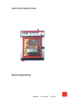
Salvis Steamer SDS 1/1 P „Vitality“
12 kW
15 kW
Installations- und Bedienungsanleitung
Instructions d’installation et mode d’emploi
Installation- and Operating Instruction
SALVIS AG
4665 Oftringen
Switzerland
www.salvis.ch
INHALTSVERZEICHNIS
1.
Vorwort ................................................ 4
2.
Sicherheit ............................................ 4
2.1
2.2
Hinweiserklärung ...................................... 4
Sicherheitshinweise .................................. 4
3.
Allgemeines ........................................ 5
3.1
3.2
3.3
3.4
Bestimmungsgemässe Verwendung ........ 5
Kennzeichnung des Produktes ................. 5
Konformität ............................................... 5
Gefahrenbereich ....................................... 5
4.
Installation ........................................... 6
4.1
4.2
4.3
4.4
4.5
4.6
4.10
Technische Daten ..................................... 6
Umgebungsbedingungen ......................... 6
Aufstellung/Platzbedarf ............................. 6
Abluft ........................................................ 6
Elektroanschluss ...................................... 6
Anschluss-/Leistungsbegrenzungssystem
(Option) .................................................... 6
Wasserablauf ........................................... 6
Wasseranschluss ..................................... 7
Zubehör zu Wasserablauf (Option) ........... 7
Zubehör zu Wasserzulauf (Option) ........... 7
Installations-Skizze ................................... 8
Anschlüsse/Detailmasse
mit und ohne Enthärter ............................. 8
Wasserenthärter ....................................... 9
5.
Bedienungs-/Anzeigeelemente ......... 10
5.1
4.7
4.8
4.8.1
4.8.2
4.9
4.9.1
6.4
6.5
6.6
6.7
6.8
6.9
6.10
6.11
6.12
6.13
6.14
6.15
6.16
6.17
6.18
6.19
Betriebsbereitschaft (Standby) erstellen . 11
Manuell Kochen ...................................... 11
Kochen mit Programmen ........................ 11
Kochphasen abfragen / löschen ............. 11
Laden von Originalkochprogrammen ...... 11
Programm abändern .............................. 11
Programm löschen ................................. 12
Neues Programm schreiben / speichern 12
Kerntemperatur-Regelung (Option) ........ 12
Einstellen der Startzeitvorwahl ................ 12
Tageszeit, Datum, Jahr einstellen ........... 12
Regenerieren des Wasserenthärters ...... 12
Ausschalten ............................................ 13
Mögliche externe Anschlüsse ................. 13
Bedienungsfehler-Anzeigen .................... 13
Störungsanzeigen ................................... 13
7.
Wartung ............................................ 14
7.1
7.2
7.2.1
7.2.2
7.2.3
7.2.4
Sicherheitshinweise ................................ 14
Reinigung ............................................... 14
Kochkammer .......................................... 14
Verschalung ............................................ 14
Tropfschale ............................................. 14
Türdichtung ............................................ 14
8.
Unterhalt ........................................... 14
8.1
Kundendienst ......................................... 14
9.
Dokumentation .................................. 14
Bedienungspanel mit Tasten / Anzeigen . 10
10.
Gültigkeit ........................................... 14
6.
Bedienung ......................................... 11
11.
Entsorgung ....................................... 14
6.1
6.2
6.3
Gefahrenhinweise ................................... 11
Anforderungen an das Bedienpersonal .. 11
Beschicken ............................................. 11
12.
Erfüllungsort/Gerichtsstand .............. 14
Copyright by SALVIS Switzerland
Aarburg, 09/2001, 10/2002
-3-
1.
Vorwort
- Die Installations- und Betriebsanleitung enthält wichtige Hinweise, um das Gerät sicher, sachgerecht und wirtschaftlich zu betreiben. Ihre Beachtung hilft, Gefahren zu vermeiden, Reparaturkosten und Ausfallzeiten zu vermindern und die Zuverlässigkeit und die Lebensdauer des Gerätes zu erhöhen.
- Die Betriebsanleitung wendet sich an alle Personen, welche mit dem Gerät arbeiten. Sie ist von jeder Person zu
lesen und anzuwenden, damit die Bedienung, Pflege und Störungsbehebung richtig gewährleistet ist.
- Die Betriebsanleitung muss ständig am Einsatzort verfügbar sein.
- Die Installationsanleitung wendet sich an alle ausgebildeten Fachleute, welche dieses Gerät installieren und in
Betrieb nehmen.
- Installationen und Reparaturen, welche nicht von autorisierten Fachleuten vorgenommen werden, sowie technische
Veränderungen am Gerät, die nicht vom Hersteller schriftlich genehmigt sind und das Verwenden von nicht Originalersatzteilen, führt zum Erlöschen der Garantie und Produktehaftung durch den Hersteller.
2.
Sicherheit
2.2 Sicherheitshinweise
Personenschutz
2.1 Hinweiserklärung
In den Hinweiskästchen finden Sie drei verschiedene
Symbole, die unbedingt beachtet werden müssen.
Die Symbole haben folgende Bedeutung:
- Das Gerät ist bei sämtlichen Montage-, Instandhaltungs- und Reparaturarbeiten auszuschalten und
gegen unbefugtes Einschalten zu sichern (Netztrennung).
Dieses Symbol ist ein Sicherheitshinweis, welches Sie bei allen Arbeitsschritten finden, bei denen Gefahr für Personen besteht. Beachten Sie diese Warnungen und verhalten Sie sich in diesen
Fällen besonders vorsichtig. Geben Sie
diese Warnungen auch an andere Benützer weiter.
Geräteschutz
Dieses Symbol finden Sie bei allen Arbeitsschritten, die besonders zu beachten sind, damit Beschädigungen an den
Geräten verhindert werden können. Geben Sie auch diese Sicherheitshinweise
an alle Gerätebenutzer weiter.
- Um ungewollten Schäden am Gerät vorzubeugen, ist
das Lesen der Betriebsanleitung erforderlich.
Ebenfalls müssen die Bediener vom Eigentümer
instruiert werden.
Generelle Sicherheitshinweise
Dieses Symbol gibt Ihnen nützliche Tips
und macht auf richtiges Vorgehen und
Verhalten aufmerksam. Beachten Sie
auch diese Hinweise. Sie können sich
damit Zeit und Probleme ersparen.
- Lesen Sie diese Betriebsanleitung zuerst sorgfältig
durch, bevor Sie das erste Mal mit diesem Gerät
arbeiten.
Die Salvis AG lehnt jede Haftung ab, wenn die
Benutzer die Hinweise missachten, welche auf den
Geräten markiert sind und/oder in der Betriebsanleitung stehen.
- Wenn anzunehmen ist, dass ein gefahrloser Betrieb
nicht mehr gewährleistet ist, muss das Gerät ausser
Betrieb gesetzt werden und gegen unbeabsichtigtes
Einschalten abgesichert werden (Netztrennung).
- Die Reparaturen dürfen nur von autorisiertem
Fachpersonal und mit Originalersatzteilen ausgeführt werden.
- Das Gerät darf nur von ausgebildeten und oder
instruierten Personen bedient werden, welche auch
mit den Sicherheitsvorkehrungen des Gerätes
vertraut sind.
- Beachten Sie neben den Hinweisen in dieser
Anleitung auch die allgemein gültigen Sicherheitsund Unfallverhütungsvorschriften.
- Die Betriebs- und Installationsanleitung muss immer
am Arbeitsplatz verfügbar sein.
-4-
3.
Allgemeines
3.1 Bestimmungsgemässe Verwendung
Der Steamer darf nur für den vorgesehenen Zweck, das
heisst für das Kochen, Dämpfen, Aufbereiten, Warmhalten und Erwärmen von Lebensmitteln verwendet werden.
3.2 Kennzeichnung des Produktes
Sie finden diese Angaben auf dem Typenschild mit
Seriennummer, Jahrgang und
- Kennzeichnung an
der Seitenwand rechts vorne (von vorne her gesehen
und oder auf der Geräteinnenseite links vorne am
Innenblech).
3.3 Konformität
EN 60335-1 + EN 60335-2-42 sind europäische Normen,
welche auch in der Schweiz den Status als anerkannte
Regel der Technik haben.
Strahlwassergeschützt nach IPX5.
-Konform.
Dieses Produkt ist
3.4 Gefahrenbereich
- Heisser Dampf tritt aus beim Öffnen der Kochkammertüre. Verbrühungsgefahr.
- Heisse Oberflächen im Bereich der Kochkammer und
der Türe. Verbrennungsgefahr.
- Der Deckel des Wasserenthärters darf während dem
Betrieb des Gerätes nicht geöffnet werden. Zum
Auffüllen des Regeneriersalzes beachten Sie bitte die
Anweisung in Kapitel 6.14.
- Keine Manipulationen am Türverschluss. Gerät steht
unter Druck!
- Am Drucksteamer dürfen nur ausgebildete Fachleute
Reparaturen vornehmen!
- Bei ausgeschaltetem Gerät wird das Wasser des
Dampferzeugers erst nach ca. 5 Minuten abgelassen.
Diese Zeit ist abzuwarten, bevor an Schläuchen usw.
des Ablaufes gearbeitet wird. Es besteht sonst akute
Verbrennungsgefahr.
- Wenn am Gerät repariert wird, muss immer eine
allseitige Netztrennung erfolgen.
ACHTUNG! Bei einer Netztrennung erfolgt die Boilerentleerung sofort. Es entweicht heisses Wasser (ca.
95°C) aus dem Boiler in den Ablauf. Verbrennungsgefahr!
-5-
4.
Installation
4.1 Technische Daten
Apparate-Typen
Leistung
Anschlusswert
Absicherung
Gewicht
SDS 1/1 P mit Enthärter
12 kW
400V 3 N AC 5 x 2.50 mm2
20 A
102 kg
SDS 1/1 P mit Enthärter
15 kW
400V 3 N AC 5 x 2.50 mm2
25 A
102 kg
SDS 1/1 P ohne Enthärter
15 kW
400V 3 N AC 5 x 2.50 mm2
25 A
97 kg
SDS 1/1 P mit Enthärter
15 kW
230V 3
40 A
102 kg
4.6 Anschluss-/Leistungsbegrenzungssystem
(Option)
4.2 Umgebungsbedingungen
Temperatur:
Feuchtigkeit:
AC 4 x 6.00 mm2
7°C - 40°C
90% relative Luftfeuchtigkeit,
nicht kondensierend.
- Dem Gerät ist ein Anschlussschema mit Anschlussbeschrieb beigelegt. Es befindet sich auf der linken Seite
im Elektrofach.
4.3 Aufstellung/Platzbedarf
4.7 Wasserablauf
- Auf Original-Salvis Untergestell oder waagrechter und
stabiler Arbeitsplatte.
- Gerät waagrecht einjustieren.
- Geringe Unebenheiten können mit den verstellbaren
Füssen ausgeglichen werden. Nachdem der Steamer
an der richtigen Stelle platziert ist, soll er mit den
4 Stück Gleitschutz (in der Kochkammer beiliegend)
gegen ein Verschieben gesichert werden.
- Mindestabstände:
links und rechts 50 mm, hinten mind. 20 mm
- Doppelstockausführung wird nicht empfohlen!
Ablauf mit offener Trennstrecke
D am pfkondensator
S chlauch
Geberit-Rohr
G 3/4"
2 cm
offene Trennstrecke
4.4 Abluft
- Eine Dunstabzugshaube ist nicht zwingend notwendig.
Jedoch sind die speziellen küchentechnischen und
örtlichen Vorschriften zu beachten.
- Wärmemenge:
latent
3500 kJ/h
fühlbar
5000 kJ/h
4.5 Elektroanschluss
- Vor Geräteanschluss, Angaben auf Typenschild
beachten an der Seitenwand rechts vorne (von vorne
her gesehen und oder auf der Geräteinnenseite links
vorne am Innenblech). Landesspezifische und örtliche
Vorschriften beachten.
- DIE GERÄTE DÜRFEN NUR DURCH AUTORISIERTE
ELEKTRO-INSTALLATEURE ANGESCHLOSSEN
WERDEN. Es müssen die örtlichen Vorschriften
eingehalten werden.
- Elektroschema im Gerät.
- Das Gerät wird mit ca. 1.5 m Kabel ohne Stecker
ausgeliefert.
- Bauseits vorsehen: Allpolige Trennvorrichtung mit
mind. 3 mm Kontaktabstand.
- Anschlusswerte/Absicherung siehe 4.1
- Eigene abgesicherte Zuleitung für jedes Gerät.
- Gerät an Potential-Ausgleich anschliessen. Die
Schraube befindet sich auf der linken Seite unter dem
Gerät und ist mit folgendem Symbol gekennzeichnet:
- Steckdose nahe am Gerät plazieren.
- Mit dampftemperaturbeständigem Schlauch,
Artikelnummer: BI 278583
- Rohr und Schlauch mit stetigem Gefälle.
- Ablauf offen in Trichter.
- Trichter nicht unter dem Gerät plazieren.
- Abstand Auslauf zum Trichter 2 cm.
Fester Ablaufanschluss mit Entlüftungstrichter
m in. 5 cm
Schlauch
G 3/4"
- Schlauch mit stetigem Gefälle montieren
- Zwischen Unterkante Steamer + Oberkante Trichter
muss ein Abstand von mindestens 5 cm sein.
- Gerät ohne Ablaufentlüftung nicht direkt an Siphon
anschliessen.
-6-
4.8 Wasseranschluss
4.8.1 Zubehör zu Wasserablauf (Option)
- Nur an kaltes Wasser in Trinkwasserqualität anschliessen.
- Bauseits: Wasserabsperrhahn und Filter (50 Mikron)
Druckreduzierventil und Rückschlagventil montieren.
1
Wasserdruck
- Netzdruck reduziert auf 3.5 bar;
- Fliessdruck min. 2.2 bar
- Fliessdruck mit Netzdruck nicht erreichbar, Druckerhöhung mit vorgeschalteter Pumpe!
- Unbedingt verhindern, dass der Anschlussdruck durch
zusätzliche Verbraucher unter 2.2 bar fallen kann!!
Anschluss für Geräte mit integriertem Enthärter
m in. 5 cm
1
2
1 Schlauch komplett
BI 278583
Hartwasseranschluss
1 Schlauch komplett
BI 278583
2 Entlüftungstrichter kompl.
BI 172448
4.8.2 Zubehör zu Wasserzulauf (Option)
Für Geräte mit integriertem Enthärter
Hartwasseranschluss
G 3/4"
G 3/4"
G 1/2"
G 3/4"
Anschluss für Geräte ohne integrierten Enthärter
G 3/4"
G 1/2"
Weichwasseranschluss
Anschlussgruppe komplett BI 172449
bestehend aus:
1 Rückschlagventil
1 Druckreduzierventil
1 Absperrhahn
Hartwasseranschluss
G 3/4"
Für Geräte ohne integrierten Enthärter
Weichwasseranschluss
Hartwasseranschluss
G 3/4"
G 3/4"
G 1/2"
Anschluss Weichwasser (Dampfaufbereitung):
- Wasser auf 0° Carbonathärtegrade enthärten durch
Gegenosmose-Anlage oder selbstregenerierende
Hauswasserenthärtungsanlage (Ionentauscher)
Anschluss Hartwasser (Dampfablöschung) an nicht
aufbereitetes Netzwasser:
- Kann auch an Weichwasser angeschlossen werden,
dann Anschluss über dieselbe Armaturengruppe
mittels Tee-Stück.
Wasserverbrauch total:
- Ca. 30 l/h (Hart- und Weichwasser)
G 3/4"
G 1/2"
Anschlussgruppe komplett 2 x BI 172449
bestehend aus: 2 Rückschlagventil
2 Druckreduzierventil
2 Absperrhahn
-7-
4.9 Installations-Skizze
min. Seitenabstand
848
50
727
50
624
20
242
382
362
680
min. Wandabstand
262
550
130
50
74
19
4.9.1 Anschlüsse/Detailmasse
mit und ohne Enthärter
29.5
107
152
126
83
85
133
70
120
150
278
Ausführung mit Enthärter
3
4
5
6
7
8
Ausführung ohne Enthärter
9
10
3
4
5
7
8
9
10
1 2
1
11
11
Legende:
1
2
3
4
5
6
Hartwasseranschluss 3/4“
Weichwasseranschluss 3/4“
HACCP; Schnittstellenanschluss
Meldeleitung LBS 2 und 3
LBS-Anschluss (Leistungsbegrenzung)
Enthärter (Salzeinfüllstutzen)
7
8
9
10
11
-8-
Elektrischer Anschluss Pg 29
Elektrischer Anschluss Pg 21
Separates Steuerungskabel LBS 3
Sicherheitsventil, Dampferzeuger
Kondensatablauf 3/4“
4.10 Wasserenthärter
- Der Wasserenthärter funktioniert gemäss dem Prinzip
des Ionenaustauschers.
- Der Behälter enthält ca. 3.0 Liter Austauschharz,
welches im regenerierten Zustand das im durchfliessenden Wasser enthaltene Calciumcarbonat Ca2O2
aufspaltet, indem das Harz die Ca-Ionen gegen NaIonen austauscht.
- Das so entstandene Na CO2 setzt sich nicht ab,
sondern wird mit dem Kondensat und Restwasser
weggeschwemmt.
- Während des Garbetriebes wird das Austauschharz
mit Ca-Ionen gesättigt, d.h. es verliert immer mehr die
Fähigkeit, das Wasser zu enthärten.
- Nach erfolgter Sättigung des Austauschharzes muss
dieses mittels ca. 0.5 Kg haushaltüblichem Regeneriersalz wieder regeneriert werden.
- Die Regenerier-Abstände sind abhängig von der
Wasserhärte.
- Die Salzlösung, welche über eine vorgegebene Zeit
mit dem Austauschharz in Berührung steht, tauscht die
Ca-Ionen wieder gegen Na-Ionen aus. Der Enthärter
ist wieder voll aufnahmefähig.
- Das Regenerieren des Wasserenthärters wird in
Kapitel 6.14 beschrieben.
- Wie man den Wasserkredit einstellt, wird in der
Beschreibung im Servicehandbuch «Einstellung des
Regenerationsintervalls der Wasserenthärter» beschrieben und ist ebenfalls jedem Gerät beigelegt
(siehe Dokument unten).
Drucksteamer FS 1/1 P „Vitality“
Einstellung des Regenerationsintervalls der Wasserenthärter
Es sind drei Enthärtertypen möglich: - Im Gerät eingebaut
- Vorgeschaltet Brita, Standard
- Vorgeschaltet Brita, Jumbo
Aufgrund der vorhandenen Wasserhärte, ist aus untenstehender Kurve der Wasserkredit-Code
abzulesen und wie folgt einzugeben:
Eingabe im Serviceprogramm:
F5 auf P5
Eingabe 1 = Brita Standard
Eingabe 2 = Brita Jumbo
Eingabe 3 = Integrierter Wasserenthärter
F5 auf P6
Eingabe-Code 1-9 je nach Härtegrad des Wassers
Code
9
S a lz -B e c h e r
Beispiel:
Code auslesen für integrierten Enthärter
Annahme, Wasserhärte 20°d = Code 5
8
7
6
BR
IT
A
5
4
Werkseinstellung
3
2
Int
erg
rie
En
r te
rW
th
är
ass
te
ere
rS
nth
ta
ärt
nd
er
ar
d/
Ju
m
bo
1
deutsche Härtegrade
5
15
10
10
30
20
25
20
35
30
50
40
70
60
englische Härtegrade
S a lz
5
10
15
20
25
30
35
40
Wasserhärte Messwerte / Einstellungen
Nr.
°deutsch
1
2
Art.-Nr. 1W 700 312
01/2001
H a rz
-9-
°franz.
°englisch
Code
°d
40
°f
französische Härtegrade
Datum
Name
45
°e
50
5.
Bedienungs-/Anzeigeelemente
5.1 Bedienungspanel mit Tasten / Anzeigen
EIN-/AUS-Taste
Programmierwahl-Taste
Anzeige Programmnummer
Anzeige Kochphasen
Aktuelle Phasen
Belegte Phasen
Anzeige Temperatur
Kochphasenwahl-Taste
Temperaturwahl-Taste
Garraum
Anzeige Zeit
Zeitwahl-Taste
Anzeige Kerntemperatur
Kerntemperatur-Wahltaste
Summer-Anzeige
Summer-Taste
Zehnertastaturblock mit
Dezimalpunkt
Eingabe aller Werte
und Funktionen
Clear-Taste
Löschen
Enter-Taste
Eingabebestätigung
Start-/Stop-Taste
Programmspeicher-Taste
Tageszeit-Taste
Startzeitvorwahl-Taste
24 Stunden
Anzeige Tageszeit
Startzeit-Vorwahl
Bedienungsfehler
Funktionsfehler
Tageszeit-Anzeige
- 10 -
6.
Bedienung
6.6 Kochen mit Programmen
P
drücken. Das zuletzt eingegebene Programm wird
angezeigt, z.B.
P
6.1 Gefahrenhinweise
- Heisser Dampf tritt aus beim Öffnen der Kochkammertüre. Verbrühungsgefahr.
- Die Behälter und Normschalenhalterungen sind heiss.
Verbrennungsgefahr.
drücken, die Diode blinkt abwechslungsweise mit
.
der Anzeige
Gewünschte Programmnummer mit 10er Tastatur
eingeben. Bereits existierende Programmplätze siehe
Programmregister.
drücken. Das Programm wird angezeigt.
drücken. Das Gerät startet.
6.2 Anforderungen an das Bedienpersonal
- Dieses Gerät darf nur von qualifiziertem und ausgebildetem Personal benutzt werden.
- Es empfiehlt sich, an einem SALVIS Anwenderseminar
teilzunehmen.
- Kochtechnische Angaben finden Sie im Kochhandbuch (Programmsteller).
- Die Bedienungsanleitung muss von jeder Person
gelesen werden, welche mit dem Gerät arbeitet.
- Während des Betriebes können alle Werte verändert
werden. Diese müssen mit Taste
- Gerät nicht überfüllen (Kochgut nicht über Oberkante
der Normschalen einfüllen).
- Achtung: Um Korrosionsschäden im Garraum und an
den Seitenkonsolen zu verhindern, soll das Kochgut
nach dem Garen gesalzen oder gewürzt werden.
Salzrückstände führen unweigerlich zu Rostfrass!!
-Taste drücken.
Zum Quittieren, die
Bei Prozessende ertönt der Summer während
20 Sekunden, bis er quittiert wird.
Ist der Summer zwischen den Kochphasen programmiert, ertönt er während 4 Sek. intermittierend.
Schreiben Sie Ihre eigenen Programme auf beiliegende Hilfsblätter und halten Sie diese unter Verschluss.
So können Sie Ihre Programme problemlos wieder
programmieren, sollten diese aus Versehen gelöscht
werden.
Die gerade aktuelle Temperatur im Garraum sowie die
-
6.4 Betriebsbereitschaft (Standby) erstellen
-
drücken, Gerät schaltet ein,
und
blinken.
Der Restwasserkredit des Weichwassers, welches vom
Wasserenthärter aufbereitet wird, erscheint in Prozenten
.
Ist dieser Kredit abgelaufen, wird eine Regeneration
notwendig (siehe Kapitel 6.15).
Nach ca. 2.5 Minuten ist der Dampferzeuger aufgeheizt.
Das Gerät ist betriebsbereit. Dies wird angezeigt durch
Blinken der Dioden P
und
.
oder
bestätigt werden. Die neuen Werte haben nur für den
gerade ablaufenden Koch-/Garprozess Gültigkeit.
- Bei Phasenende ertönt der Summer intermittierend,
wenn programmiert.
6.3 Beschicken
Anzeigen P
.
gewählte Zeit können mit der Taste . jederzeit
abgefragt werden.
- Der Kochtemperaturbereich im Garraum liegt zwischen 50° - 119°C. Werden tiefere oder höhere Werte
eingeben, so werden diese vom Programm nicht
akzeptiert. Zu tiefe Temperaturen springen automatisch auf 50°C und zu hohe auf 119°C.
6.7 Kochphasen abfragen / löschen
1 -3
C
Anzeige der Phase 2 von 3 Phasen
drücken, Phase 2 wird gelöscht
6.5 Manuell Kochen
Neue Anzeige.
Die nachfolgenden Phasen rutschen automatisch nach.
drücken. Die zuletzt eingegebenen Werte werden
angezeigt.
6.8 Laden von Originalkochprogrammen
erneut drücken, Diode blinkt rot. Im Anzeigenfeld
.
erscheint
Neuen Wert über 10er Tastatur eingeben;
Nach Programmnummer-Eingabe, Tasten
und P
drücken. In der Programmnummernanzeige erscheint
ein Punkt. Das Programm kann beliebig verändert
werden. Das Originalprogramm ist noch vorhanden.
drücken, Diode blinkt rot.
Im Anzeigenfeld erscheint
.
Neuen Wert über 10er Tastatur eingeben;
drücken, um die Eingabe zu bestätigen.
drücken, Gerät startet.
6.9 Programm abändern
P
abrufen. Gewünschte Werte ändern.
Mit Tastenfolge M
- 11 -
neue Werte speichern.
6.10 Programm löschen
P
letzte Eingabe erscheint
zu löschendes Programm
drücken, Diode blinkt
P
drücken und Programmnummer
eingeben.
Mit folgender Tastenkombination Programm löschen.
C
M
Anzeige
mit 10er Tastatur Zeit eingeben
Programmnummer
drücken zum Speichern
6.11 Neues Programm schreiben / speichern
drücken, Anzeigen verlöschen.
drücken, Gerät schaltet ein.
P
+
Gerät startet selbständig.
Dioden blinken.
Wenn das Kochprogramm beendet ist, ertönt der
Summer.
P drücken, die zuletzt eingegebene Programmnummer wird angezeigt.
- Durch Drücken der Taste
werden die Anzeigen
beleuchtet und die Uhrzeit wird angezeigt.
blinken.
P drücken,
Eingabe einer freien Programmnummer
(siehe Programmregister), z.B.
Eine leere Programmnummer kann auch durch Drücken
von M
und 0 ausgelesen werden.
1. Phase programmieren:
drücken,
1 -3
und P
oder Dioden
2. und 3. Phase programmieren:
blinken.
Tageszeiteingabe:
erscheint.
drücken
Stunden und Minuten eingeben.
2x drücken,
erscheint.
Analog 1. Phase programmieren.
Speichern der Daten.
1 -3
drücken,
P
Entweder
drücken zum Bestätigen.
M
.
Zum Einstellen muss das Gerät in eingeschaltetem
Zustand sein.
drücken, Wert eingeben, z.B.
2x drücken,
Drücken der Taste .
6.14 Tageszeit, Datum, Jahr einstellen
erscheint.
drücken, Wert eingeben, z.B.
1 -3
und
drücken, um in den Startzeit- Tasten
vorwahl-Modus zurückzukehren.
- Ist-Zeit und Programmnummer abfragen durch
Mit der .
-Taste Stunden und Minuten trennen.
drücken zum Bestätigen
blinken.
Eingabe des Datums:
Programmnummer eingeben
, dann
drücken zum Speichern
drücken
Tag und Monat eingeben.
6.12 Kerntemperatur-Regelung (Option)
- Kerntemperatur-Fühlerspitze in die Mitte des Gargutes
stecken. Türe schliessen.
P
Mit der .
drücken zum Bestätigen
Eingabe des Jahres:
Programm wählen oder
, dann
Garraumtemperatur wählen
starten
Zeitschaltuhr ist ausser Funktion
Nach Erreichen der vorgewählten Temperatur, ertönt
der Summer oder der Prozess springt zur nächsten
Phase.
Ist der Fühler nicht im Gargut eingesteckt, so erhöht
sich die Fühlertemperatur zu schnell. Ein Bedienungsfehler 12 wird angezeigt.
Summer ertönt, bis Quittierung erfolgt.
Soll die Kerntemperatur nach Erreichen erhöht
werden, ist eine Temperaturdifferenz von mind. +3°C
notwendig.
-
-
6.13 Einstellen der Startzeitvorwahl
P
Gewünschtes Kochprogramm eingeben
drücken, Diode blinkt
drücken
Jahr eingeben
Kerntemperatur wählen 20 - 100°C
-
-Taste Tag und Monat trennen.
drücken zum Bestätigen
drücken, retour auf Tageszeit.
Achtung: Nach längerem Netzunterbruch muss die
Tageszeit wieder eingestellt werden.
6.15 Regenerieren des Wasserenthärters
- Wenn Anzeige
leuchtet, können je nach
Wasserkredit weitere Garprozesse gestartet werden.
leuchtet, muss das Gerät
- Wenn Anzeige
regeneriert werden.
Bei dieser Anzeige wird der Normalbetrieb blockiert.
Es kann kein neuer Garprozess gestartet werden.
Zudem muss sichergestellt werden, dass der aktuelle
Garprozess vor der Regeneration vollständig abgelaufen ist.
- 12 -
- Starten des Regenerationsprozesses nach der
(freiwillig)
Anzeige
Taste P
drücken und Programm
wählen.
betätigen und Start-/Stop Taste
drücken.
- Starten des Regenerationsprozesses nach der
Anzeige
Programm
(obligatorisch)
wird bereits angezeigt.
betätigen und Start-/Stop Taste
drücken.
Weiteres Vorgehen für beide Varianten:
Der Dampferzeuger wird entleert. Warten bis der
Summer ertönt. Die Anzeige
Deckel vom Wasserenthärter entfernen.
Bestätigen mit
HACCP-Protokolldrucker
Voraussetzung: Muss im Servicebaum angemeldet sein.
Die Drucksprache muss angewählt sein.
Ist ein HACCP-Protokolldrucker am Gerät angeschlossen, kann das Druckerintervall vom Betreiber wie folgt
geändert werden:
- Steuerung ausschalten.
-
erscheint.
. Warten bis der Summer ertönt und
-
Taste gedrückt halten und Steuerung einschalten.
Taste drücken. Mittels Ziffertasten IntervallNeueingabe.
Taste drücken zum Bestätigen.
- Drucker einschalten.
Mit dem Start des Garprozesses wird der Ausdruck
automatisch gestartet. Es ist möglich, die Zähler und
Einstell-Parameter auszudrucken. Im Select-Modus
, der Summer verstummt.
Während 1 - 3 mal 15 Sekunden wird die Leitfähigkeit
des Wassers gemessen. Ein hörbares Fliessen des
Wassers durch den Basenaustauscher ist vernehmbar.
Wenn die Leitfähigkeit in Ordnung ist, erscheint in der
(LED blinken) Tasten .
und C
drücken.
6.18 Bedienungsfehler-Anzeigen
die Regenerationszeit
Minuten.
Zeitanzeige
Der Regenerationsprozess läuft ab.
Wurde kein Salz aufgefüllt und nur die Betätigungstaste
Diese erscheinen 2-stellig in der Zeitanzeige, gleichzeitig ertönt der Summer.
Kerntemperaturfühler ist nicht eingesteckt
oder die eingegebene Temperatur ist tiefer
als die gemessene Temperatur.
In einer Kochphase sind die eingegebenen
Werte verloren gegangen. Gerät abschalten
und Programm neu abrufen.
gedrückt (Leitfähigkeit zu tief), muss die Taste
nochmals betätigt werden.
.
Es erscheint automatisch die Anzeige
Der ganze Vorgang muss mit Salz wiederholt werden.
drücken zum Summer abstellen.
6.16 Ausschalten
drücken. Das Gerät ist ausgeschaltet.
6.19 Störungsanzeigen
Nach 5 Minuten entleert sich der Boiler selbständig.
Erscheint 2-stellig in der Zeitanzeige. Gleichzeitig ertönt
der Summer.
Garraumfühler Unterbruch
Garraumfühler Kurzschluss
Wir empfehlen, das Gerät erst dann auszuschalten,
wenn es nicht mehr benötigt wird. Damit verhindert man
das Entleeren des Boilers, das Gerät bleibt in Bereitschaftsbetrieb.
Sie sparen Energie, gleichzeitig wird der Regenerierzyklus verlängert, weil der Boiler weniger oft gefüllt werden
muss.
Thermoelement Niveausonde Leerlauf
Thermoelement Niveausonde Kurzschluss
Timeout Wasserniveau
Timeout Druckschalter
Sicherheitsdruckschalter Dampferzeuger
Problem Heizungsschütz
6.17 Mögliche externe Anschlüsse
Salvis Cuisine Control (Küchenleitsystem)
Voraussetzung: Schnittstelle RS485 im Gerät aktiviert.
Hauptmenus unter anderem:
- Geräteüberwachung mit automatischer
HACCP-Dokumentation
- Energieoptimierung
- Kühlhaus-Temperaturüberwachung
- Gerätesteuerung vom zentralen Leitstand
- Frühwarn- und Alarmsystem
- u.s.w.
P
Es erscheint
in der Temperaturanzeige.
In der Zeitanzeige erscheint das aktuelle Druckintervall in Minuten.
erscheint.
in der Anzeige
Sicherstellen, dass der Wasserstand im Basenaustauscher knapp unterhalb des Einfüllstutzens ist.
Mit dem mitgelieferten Massbecher 0.5 kg Regeneriersalz einfüllen.
Deckel des Wasserenthärters wieder schliessen.
Bestätigen mit
Salvis Data-Manager
Voraussetzung: Freigabe Schnittstelle RS232 und
Anschluss auf PC über Konverterkabel
Eigenschaften: Verwaltung der Combi- und DruckSteamer Programme auf dem PC. Programme neu
schreiben, abändern sowie up- und download zu den
Geräten.
Kerntemperaturfühler Unterbruch (es kann
ohne Fühler weitergearbeitet werden).
Kerntemperaturfühler Kurzschluss (es kann
ohne Fühler weitergearbeitet werden).
Leitfähigkeit des Wassers nach Regeneration zu hoch. Regeneration OHNE SALZ
wiederholen.
Bei Anzeige einer dieser Störungen, Gerät ausschalten.
Der Summer stellt ab. Servicestelle benachrichtigen.
- 13 -
7.
Wartung
8.
7.1 Sicherheitshinweise
8.1 Kundendienst
- Bei Störungsfällen am Drucksteamer, kontaktieren Sie
bitte Ihren regionalen SALVIS-Vertreter oder wenden
Sie sich bitte an den SALVIS-Kundendienst in Aarburg.
- Geben Sie bitte bei jeder Meldung an unsere Servicestelle die Apparatenummer sowie den Typ an. Sie
finden diese Angaben auf dem Typenschild an der
Seitenwand rechts vorne (von vorne her gesehen und
oder auf der Geräteinnenseite links vorne am Innenblech).
- Wartungsarbeiten dürfen nur vom Fachmann und am
vom Netz getrennten und abgekühlten Gerät ausgeführt werden.
7.2 Reinigung
9.
- Zum Reinigen des Gerätes keine chlor-, säure- oder
metallhaltigen Zusätze sowie keine Scheuermittel oder
Stahlscheurschwämme verwenden.
- Nur lebensmitteltaugliche Reinigungsmittel verwenden.
- Keinen Hochdruckreiniger oder
Wasserschlauch verwenden.
7.2.1 Kochkammer
- Die Kochkammer wie folgt täglich reinigen:
- Die Normschalenhalterungen links und rechts (1)
anheben und aus der Kochkammer ziehen.
- Kochgutreste aus der Kochkammer entfernen.
- Kochkammer und Normschalenhalterungen mit
Wasser und einem milden Reinigungsmittel reinigen,
spülen und mit einem sauberen, trockenen Lappen
austrocknen.
- Sieb (2) entfernen und reinigen.
- Achtung: Durch ungenügende Reinigung entstandene
Salzrückstände führen unweigerlich zu Rostfrass!
7.2.2 Verschalung
- Die Verschalungsbleche sind aus rostfreiem Stahl und
können mit einem handelsüblichen Chrom-stahlreiniger gereinigt werden. Wir empfehlen Ihnen den
Reinigungs-Spray mit der Artikelnummer: BK 176204
7.2.3 Tropfschale
- Die Tropfschale (3) nach vorne aushängen, entleeren,
reinigen und wieder einhängen.
2
3
Dokumentation
- Diese Dokumentation ist gemäss Urheberrecht unser
geistiges Eigentum und darf nur zum eigenen Gebrauch kopiert werden. Kopien, auch nur auszugsweise, benötigen die schriftliche Erlaubnis der Firma
Salvis AG, Aarburg.
10. Gültigkeit
- Ohne anderslautende Mitteilung ist diese Dokumentation in allen Teilen gültig . Es können jedoch ohne
vorherige Mitteilung Masse und Aussehen der Produkte ändern.
11. Entsorgung
- Die Entsorgung ist Sache des Kunden. Das Gerät
kann problemlos der nächsten Altmetallsammlung
übergeben werden. Es wurde bei der Produktion kein
Material verwendet, welches als Sondermüll entsorgt
werden müsste.
- Die Elektronikteile müssen speziell entsorgt werden.
Wenden Sie sich bitte an eine lokale Recycling-Firma.
12. Erfüllungsort/Gerichtsstand
- Erfüllungsort und Gerichtsstand ist Aarburg. Dies gilt
auch dann, wenn auswärtige die Montage übernommen haben. Zur Anwendung kommt immer die
schweizerische Rechtssprechung.
7.2.4 Türdichtung
- Türdichtung (4) entfernen und mit sauberem und
säurefreiem Abwaschmittel reinigen.
- Dichtungsfläche mit einem feinen «Scotch-Brite»
Schwamm reinigen, bevor die Türdichtung wieder an
der Türe angebracht wird.
1
Unterhalt
4
- 14 -
TABLE DES MATIÈRES
1.
Avant-propos .......................................... 16
2.
2.1
2.2
Sécurité .................................................. 16
Légende des remarques ......................... 16
Remarques concernant la sécurité ......... 16
3.
3.1
3.2
3.3
3.4
Généralités ............................................. 17
Utilisation appropriée .............................. 17
Designation distinctif du produit .............. 17
Conformité .............................................. 17
Zones de dangers .................................. 17
6.9
6.10
6.11
4.
4.1
4.2
4.3
4.4
4.5
4.6
Installation .............................................. 18
Données techniques ............................... 18
Conditions environnementales ............... 18
Emplacement / espace utile ................... 18
Aération .................................................. 18
Raccordement électrique ........................ 18
Raccordement du système de limitation
de puissance (Option) ............................ 18
Evacuation d’eau .................................... 18
Raccordement d’eau .............................. 19
Accessoires pour évacuation d’eau
(Option) .................................................. 19
Accessoires pour alimentation d’eau
(Option) .................................................. 19
Esquisse d’installation ............................ 20
Raccordements/mensurations détaillées
avec ou sans adoucisseur ...................... 20
Adoucisseur d’eau .................................. 21
6.13
6.14
4.7
4.8
4.8.1
4.8.2
4.9
4.9.1
4.10
5.
5.1
Eléments de commande et d’affichage ... 22
Tableau de commande à touches /
Affichage ................................................ 22
6.
6.1.
6.2
6.3
6.4
Utilisation ................................................ 23
Signalement des dangers ....................... 23
Exigences envers le personnel utilisateur 23
Chargement ........................................... 23
Etablir la situation d’attente (Standby) ..... 23
6.5
6.6
6.7
6.15
6.16
6.17
6.18
6.19
Cuisson manuelle ................................... 23
Cuisson avec programme ....................... 23
Interrogation / annulation des phases
de cuisson .............................................. 23
Chargement de programmes de cuisson
originaux ................................................. 23
Modification de programmes .................. 23
Effacement de programmes ................... 24
Ecrire et mémoriser un nouveau
programme ............................................. 24
Réglage de la température à coeur
(Option) .................................................. 24
Réglage de la minuterie de démarrage ... 24
Réglage de l’heure, du jour, de la date
et de l’année ........................................... 24
Régenération .......................................... 24
Mettre hors service ................................. 25
Branchements externes possibles .......... 25
Affichage d’erreurs de manipulation ....... 25
Affichage d’erreurs de fonctionnement ... 25
7.
7.1
7.2
7.2.1
7.2.2
7.2.3
7.2.4
Maintenance ........................................... 26
Indication de sécurité .............................. 26
Nettoyage ............................................... 26
Chambre de cuisson .............................. 26
Coffrage ................................................. 26
Egouttoir ................................................. 26
Joint de porte .......................................... 26
8.
8.1
Entretien ................................................. 26
Service clientèle ..................................... 26
9.
Documentation ....................................... 26
10.
Validité .................................................... 26
11.
Elimination .............................................. 26
12.
Lieu d’exécution / siege .......................... 26
6.8
6.12
- 15 -
1.
Avant-propos
- Les instructions d’installation et mode d’emploi contiennent d’importants signes et recommandations aidant à
l’utilisation correcte et économique de l’appareil. Leur observation permet d’éviter des risques de tous genres, de
réduire les coûts des réparations et des durées d’immobilisation ainsi que d’augmenter la fiabilité et la longévité de
l’appareil.
- Le mode d’emploi est destiné à toutes personnes appelées à travailler avec l’appareil. Il doit être lu et mis en
pratique par chaque utilisateur afin que l’emploi, l’entretien et l’élimination des dérangements soient effectués
correctement.
- Le mode d’emploi doit être constamment à portée de main sur la place de travail
- L’instruction d’installation s’adresse à des professionnels formés, aptes à installer l’appareil et à le mettre en
service.
- Les installations et réparations qui ne sont pas exécutées par des professionnels autorisés de même que les
modifications techniques de l’appareil non agrées par écrit par le fabricant ou encore l’utilisation de pièces détachées qui ne sont pas d’origine, entraînent l’extinction de la garantie et de la responsabilité inhérente au produit.
2.
Sécurité
2.2 Remarques concernant la sécurité
Protection des personnes
2.1 Légende des remarques
Dans les cases de remarque, vous trouverez trois
symboles différents qui doivent absolument être
observés. Les symboles ont les significations suivantes :
- Lors de tous les travaux de montage, d’entretien et
de réparation, couper le courant aux appareils et les
protéger contre une remise du contact intempestive.
Ce symbole introduit une remarque sur
la sécurité et vous le trouverez avec toutes les opérations de travail pour lesquelles il y a un danger pour les personnes.
Veuillez observer ces avertissements et
vous comporter dans ces cas avec une
prudence particulière. Communiquez ces
avertissements aux autres utilisateurs.
Protection des appareils
- Pour prévenir des destructions accidentelles des
appareils, il est nécessaire d’en lire les instructions
d’utilisation. De même, les servants doivent être
instruits par le propriétaire.
Ce symbole accompagne la description
des procédures qu’il faut particulièrement
observer pour éviter des dommages aux
appareils. Communiquez aussi ces avertissements aux autres utilisateurs.
Remarques générales sur la sécurité
Ce symbole donne des conseils utiles et
vous familiarise avec les démarches et
comportements les plus adéquats. En
observant ces remarques, vous pouvez
contourner des difficultés et gagner du
temps.
- Veuillez lire attentivement les présentes instructions
d’utilisation avant de travailler avec cet appareil pour
la première fois.
- S’il faut redouter qu’une explotation sans danger ne
soit plus assurée, il faut mettre les appareils et leurs
composants hors fonction et les protéger d’une
remise en marche inopinée.
Salvis décline toute responsabilité si l’utilisateur
néglige d’observer les instructions marquées sur
l’appareil ou énoncées dans la notice d’utilisation.
- Les réparations ne doivent être effectuées que par
un personnel qualifié et habilité, utilisant des pièces
de rechange d’origine.
- Les appareils ne doivent être servis que par un
personnel formé et instruit en conséquence, familiarisé avec les mesures de sécurité des appareils et
de leurs composants.
- Outre les instructions contenues dans la présente
notice, veuillez aussi observer les consignes
générales de sécurité et de prévention des accidents
en vigueur.
- La notice d’utilisation doit toujours être disponible au
poste de travail.
- 16 -
3.
Généralités
3.1 Utilisation appropriée
Le Steamer ne doit être utilisé qu’à des tâches pour
lesquelles il a été conçu, c’est-à-dire, pour cuire,
vaporiser, régénérer, maintenir au chaud et réchauffer
des denrées alimentaires.
3.2 Designation distinctif du produit
Les indications telles que le n° de série, l’année de
construction et la designation
figurent sur la plaquette signalétique placée sur la paroi extérieure à l’avant
droit de l’appareil (vu de devant et/ou sur le côté intérieur de l’appareil à l’avant gauche de la tôle intérieure).
3.3 Conformité
EN 60335-1 + EN 60335-2-42 sont des normes
européennes qui ont également en Suisse le statut de
règle reconnue de la technique.
Protection contre les éclaboussures selon IPX5
Ce produit est conforme aux exigences de la
.
3.4 Zones de dangers
- De la vapeur chaude s’échappe au moment de
l’ouverture de la chambre de cuisson. Danger de
brûlures.
- Surfaces chaudes dans la zone de la chambre de
cuisson et de la porte. Danger de brûlures.
- Le couvercle de l’adoucisseur d’eau ne doit pas être
ouvert durant le fonctionnement de l’appareil. Pour le
remplissage de sels régénérateurs, veuillez consulter
le chapitre 6.14 du mode d’emploi.
- Ne pas manipuler la fermeture de la porte lorsque
l’appareil est sous pression. Seules des personnes
spécialement formées sont autorisées à entreprendre
une réparation sur ce steamer à pression.
- Lors de l’arrêt de l’appareil, l’eau du générateur de
vapeur n’est évacuée qu’après 5 minutes environ.
Ce laps de temps est à observer avant d’entreprendre
un travail sur les tuyaux de l’écoulement faute de quoi
on s’expose à un grave danger de brûlures.
- Durant une réparation de l’appareil, il est impératif de
le déconnecter totalement du secteur.
ATTENTION ! Au moment de la déconnexion de
l’appareil la vidange du chauffe-eau s’effectue instantanément. L’eau chaude (env. 95°C) se déverse alors
dans l’écoulement. Danger de brûlures!
- 17 -
4.
Installation
4.1 Données techniques
Type d'appareil
Puissance
Données de raccordement
Fusible de
sureté
Poids
SDS 1/1 P avec adoucisseur
12 kW
400V 3 N AC 5 x 2.50 mm2
20 A
102 kg
SDS 1/1 P avec adoucisseur
15 kW
400V 3 N AC 5 x 2.50 mm2
25 A
102 kg
SDS 1/1 P sans adoucisseur
15 kW
400V 3 N AC 5 x 2.50 mm2
25 A
97 kg
SDS 1/1 P avec adoucisseur
15 kW
230V 3
40 A
102 kg
4.2 Conditions environnementales
Température:
Humidité:
AC 4 x 6.00 mm2
4.6 Raccordement du système de limitation
de puissance (Option)
7°C - 40°C
90% d’humidité relative
exempte de condensation.
- Un schéma de connexion avec une description du
raccordement est joint à la machine. Il se trouve du
côté gauche, dans le boîtier électrique.
4.3 Emplacement / espace utile
4.7 Evacuation d’eau
- Sur console Salvis originale ou table de travail stable
et de niveau.
- Régler la mise au niveau de l’appareil.
- De légères différences de niveau peuvent être compensées grâce aux pieds réglable du steamer. Après
sa mise en place correcte la stabilité de l’appareil doit
être assurée au moyen des 4 protections anti-glissement (jointes dans la chambre de cuisson).
- Espacements minimum:
à gauche et à droite: 50 mm, à l’arrière: 20 mm
- Disposition à étage n’est pas recommandé.
Ecoulement avec distance de séparation ouverte
C on densateur
de vap eur
T ube
Tuyau Geberit
2 cm
Distance de séparation ouverte
4.4 Aération
- Une hotte d’aération n’est pas absolument nécessaire.
Il convient cependant d’observer les prescriptions
spéciales en matière de technique culinaire ainsi que
les réglementations locales.
- Quantité de chaleur: latent
3500 kJ/h
sensible 5000 kJ/h
4.5 Raccordement électrique
- Avant de raccorder l’appareil, voir les indications
figurant sur la plaquette signalétique placée sur la
paroi extérieure à l’avant droit de l’appareil (vu de
devant et/ou sur le côté intérieur de l’appareil à l’avant
gauche de la tôle intérieure). Les prescriptions
spécifiques du pays et de la localité sont à observer.
- LES APPAREILS NE PEUVENT ETRE RACCORDES
QUE PAR UN ELECTRO-INSTALLATEUR AUTORISE.
Les prescriptions locales doivent être respectées.
- Le schéma électrique se trouve dans l’appareil.
- L’appareil est livré avec env. 1.5 m de câble, sans
fiche de connexion.
- A prévoir dans le local d’installation :dispositif de
coupure sur tous les pôles avec un écartement des
contacts de 3 mm au minimum.
- Données de raccordement / fusibles de sécurité, voir
page 4.1
- Conduite d’alimentation sécurisée individuelle pour
chaque appareil.
- Relier l’appareil à la compensation de potentiel. La vis
se trouve du côté gauche, sous l’appareil et est
désignée par ce symbole:
- Placer la prise à proximité de l’appareil.
G 3/4"
- Avec tube résistant à la température, numéro d’article
BI 278583.
- Tuyau et tube à inclinaison constante
- Ecoulement ouvert dans entonnoir
- L’entonnoir n’est pas situé sous l’appareil
- Distance de la sortie à l’entonnoir : 2 cm
Raccordement d’écoulement fixe avec entonnoir de
ventilation
m in. 5 cm
Tu yau
G 3/4"
- Monter le tube avec une inclinaison latérale
- Bord inférieur Steamer / bord inférieur de l’entonnoir =
min. 5 cm
- Ne pas raccorder directement au siphon l’appareil
sans écoulement ventilé.
- 18 -
4.8 Raccordement d’eau
4.8.1 Accessoires pour évacuation d’eau
(Option)
- Ne raccorder qu’à de l’eau froide potable
- Equipement du local: robinet de fermeture d’eau et
filtre (50 microns), vanne de réduction de pression et
soupape de retenue.
1
Pression de l’eau
- Pression de réseau réduite à 3.5 bars
- Pression d’écoulement min. 2.2 bar
- Si la pression d’écoulement min. n’est pas atteinte,
installer une pompe de surpression !
- Empêcher que la pression d’eau soit réduite inférieur
2.2 bar par d’autres consommateurs.
m in. 5 cm
1
2
1 Tube compl.
BI 278583
Raccordement pour appareils avec adoucisseur
intégré
1 Tube compl.
BI 278583
2 Entonnoir de ventilation cpl.
BI 172448
Raccordement d'eau
non adoucie
4.8.2 Accessoires pour alimentation d’eau
(Option)
Pour appareils avec adoucisseur intégré
G 3/4"
Raccordement d'eau
non adoucie
G 3/4"
G 1/2"
G 3/4"
Raccordement pour appareils sans adoucisseur
intégré
Raccordement d'eau adoucie
G 3/4"
G 1/2"
Raccordement d'eau non adoucie
Groupe de raccordement compl. BI 172449
comprenant: 1 Soupape de retenue
1 Vanne de réduction de pression
1 Robinet de fermeture d’eau
G 3/4"
Pour appareils sans adoucisseur intégré
Raccordement d'eau adoucie
Raccordement d'eau non adoucie
G 3/4"
G 1/2"
G 3/4"
Raccordement d’eau adoucie (préparation de vapeur):
- Adoucier l’eau à 0° dureté carbonate par:
Osmose inverse
Adoucissement par échange d’ions
Raccordement de l’eau non adoucie du réseau (condensation de vapeur):
- Le branchement peut aussi se faire à l’eau adoucie
avec un té sur le même groupe de raccordement.
Consommation d’eau maximum:
- Env. 30 l/h (eau adoucie et non adoucie)
G 3/4"
G 1/2"
Groupe de raccordement compl. 2 x BI 172449
comprenant: 2 Soupape de retenue
2 Vanne de réduction de pression
2 Robinet de fermeture d’eau
- 19 -
4.9 Esquisse d’installation
Espace latéral min.
848
50
727
50
624
20
242
382
362
680
Espace mural min.
262
550
130
50
74
19
4.9.1 Raccordements/mensurations détaillées
avec ou sans adoucisseur
29.5
107
152
126
83
85
133
70
120
150
278
Exécution avec adoucisseur
3
4
5
6
7
8
9
Exécution sans adoucisseur
10
3
5
7
8
9
10
1 2
1
11
11
Légende:
1
2
3
4
5
4
Raccordement d’eau 3/4“ HW (eau non adoucie)
Eau adoucie 3/4“
HACCP; raccordement des intersections
Ligne d’ordres LBS 2 und 3
Raccordement LBS (limitation de puissance)
6
7
8
9
10
11
- 20 -
Adoucisseur (manchon de remplissage de sel)
Raccordement électrique Pg 29
Raccordement électrique Pg 21
Câble de commande séparé LBS 3
Vanne de sécurité, génerateur de vapeur
Raccordement d’eau 3/4“ HW (eau non adoucie)
4.10 Adoucisseur d’eau
- L’adoucisseur d’eau fonctionne selon le principe de
l’échangeur d’ions
- Le récipient contient env. 3.0 litres de résine
d’échange d’ions qui, à l’état régénéré, décompose le
carbonate de calcium Ca202 contenu dans l’eau du
fait que la résine échange les ions CA contre des ions
Na.
- Le CO2 Na qui en résulte ne se dépose pas mais est
évacué avec les eaux résiduelles et de condensation.
- Au cours du processus de cuisson, la résine
d’échange se sature d’ions CA et perd donc progressivement ses propriétés d’adoucisseur d’eau.
- Lorsque la résine d’échange est saturée, celle-ci doit
être régénérée au moyen d’env. 0.5 kg de sel régénérateur utilisé habituellement dans les ménages.
- La fréquence des régénérations dépend du degré de
dureté de l’eau.
- La solution salée qui, pendant un laps de temps
donné, est en contact avec la résine d’échange,
remplace à nouveau les ions CA par des ions NA.
L’adoucisseur retrouve alors toutes ses propriétés.
- La régénération de l’adoucisseur d’eau est décrite au
chapitre 6.14.
- La manière de régler la réserve d’eau est décrite dans
le chapitre « Réglage de l’intervalle des régénérations
de l’adoucisseur d’eau » du manuel de service qui est
également joint à chaque appareil (voir document cidessous).
Cuiseur à vapeur FS 1/1 P „Vitality“
Réglage de l’intervalle régénération de l‘adoucisseur
Il y a 3 types d’adoucisseurs:
- Intégré dans l’appareil
- Installé Brita, Standard
- Installé Brita, Jumbo
En référence de la dureté d’eau actuelle, le code du crédit d’eau est sélectionné selon le graphique
ci-dessous et programmer de la manière suivante:
Entrer dans le programme de service:
F5 sur P5
Entrer 1 = Brita Standard
Entrer 2 = Brita Jumbo
Entrer 3 = Adoucisseur intégré
F5 sur P6
Entrer le Code 1-9 dépendent la dureté d’eau
Code
9
G o b e le t
à s e l
Example:
Lire le code pour l'adoucisseur intégré
Hypothèse, dureté d'eau 36°f = Code 5
8
7
Ad
ou
c
6
5
4
Réglage à l'usine
is
se
ur
BR
IT
A
3
2
Ad
ou
c is
seu
r in
tég
ré
St
an
da
rd
/J
um
bo
1
dureté allemand
5
15
10
10
30
20
25
20
35
30
dureté française
50
40
70
60
dureté anglais
5
S e l
10
15
20
25
30
35
40
Dureté d’eau valeurs / Ajustage
No.
°Allemand
°Français
1
2
No. de pièce 1W 700 312
01/2001
R é s in e
- 21 -
°Anglais
Code
Date
Nom
45
°d
40
°f
°e
50
5.
Eléments de commande et d’affichage
5.1 Tableau de commande à touches /
Affichage
Touche Marche/Arrêt
Touche de sélection des programmes
Touche de sélection des phases
de cuisson
Affichage du numéro du programme
Affichage; Phases de cuisson
Phase actuelle
Phases occupées
Touche de sélection de la température chambre de cuisson
Affichage de la température
Touche de sélection de la durée
Affichage de la durée
Touche de sélection de la
température à coeur
Affichage de la température à ceour
Touche du signal sonore
Affichage signal sonore
Clavier numérique avec
point décimal
Entrée de toutes les
valeurs et fonctions
Touche d’annulation
Annuller
Touche Entrée
Confirmation de saisie
Touche de démarrage/stop
Début/Fin de la cuisson
Touche d’enregistrement
des programmes
Touche de l’heure
Touche de programmation
du démarrage 24 heures
Affichage Heure
Heure de démarrage programmée
Erreur de manipulation
Erreur de fonctionnement
Indication de l’heure
- 22 -
6.
Utilisation
6.6 Cuisson avec programme
Presser P
. Le dernier programme enregistré est
affiché, par exemple
Presser P
6.1. Signalement des dangers
.
, la diode clignote alternant avec l’affichage
.
Entrer le programme désiré au moyen du clavier à
10 touches. Voir les emplacements de programmes déjà
existants dans le registre des programmes.
- De la vapeur chaude s’échappe lors de l’ouverture de
la chambre de cuisson. Danger de brûlures.
- Les récipients et supports des bacs normalisés sont
chauds. Danger de brûlures.
Appuyer
le programme s’affiche. Appuyer
.
6.2 Exigences envers le personnel utilisateur
L’appareil démarre.
- Cet appareil ne peut être utilisé que par des personnes
qualifiées et formées.
- Il est recommandé de participer à un séminaire pour
utilisateurs de Salvis.
- Des indications de technique culinaire figurent dans le
manuel de cuisine (porte-programme).
- Le mode d’emploi doit être lu par chaque personne
appelée à travailler avec l’appareil.
- Durant le fonctionnement, toutes les valeurs peuvent
être modifiées. Celles-ci doivent être confirmées avec
6.3 Chargement
6.4 Etablir la situation d’attente (Standby)
, l’appareil s’enclenche.
Les indicateurs P
et
vérifiés avec la touche . .
- La température à l’intérieur de la chambre de cuisson
peut s’échelonner entre 50° à 119°C. Lorsque des
températures inférieures ou supérieures sont entrées,
elles sont refusées par le programme. Les températures trop basses sont automatiquement portées à
50°C et celles trop élevées, ramenées à 119°C.
clignotent
Le crédit restant de l’eau adoucie, produite par l’adou.
cisseur d’eau, apparaît en pourcentage
Lorsque ce crédit est épuisé, une régénération est
nécessaire (voir chapitre 6.15).
Après env. 2.5 minutes, le générateur de vapeur est
chauffé. L’appareil est en situation d’attente, prêt au
fonctionnement. Ceci est signalé par le clignotement des
diodes P
et
Presser
.
Les dernières valeurs enregistrées sont affichées.
Presser à nouveau
, la diode clignote rouge.
.
Dans le champ d’affichage apparait
Entrer la nouvelle valeur au moyen du clavier à 10
touches.
, la diode clignote rouge.
Sur l’affichage apparait
.
Entrer la nouvelle valeur au moyen du clavier à 10
touches.
Presser
Presser
affichage de la phase 2 de 3 phases
Presser C
6.5 Cuisson manuelle
Presser
6.7 Interrogation / annulation des phases
de cuisson
1 -3
.
pour confirmer l’entrée.
, l’appareil démarre.
. Les nouvelles valeurs ne s’appli-
.
tancer, presser la touche
- A la fin du processus, le signal sonore retentit pour
20 sec. jusqu’à ce qu’il soit quittancé.
- Si le signal sonore est programmé entre les phases à
cuisson, il retentit par intermittance pendent 4 sec.
- Ecrivez vos propres programmes sur les feuilles d’aide
ci-jointes et conservez-les sous clé. Vous pourrez ainsi
reprogrammer vos processus sans problème dans le
cas où ils auraient été effacés par inadvertance.
- La température actuelle dans la chambre de cuisson et
le temps de cuisson choisit peuvent à tout instant être
- Ne pas surcharger l’appareil (ne pas remplir les bacs
normalisés au-delà de la bordure supérieure).
- Attention: Afin d’éviter des dommages de corrosion
dans la chambre de cuisson et sur les consoles
latérales, les aliments doivent être salés et épicés
après leur cuisson. Les résidus de sel entraînent
inévitablement la rouille !!
Appuyez sur
ou
quent que pour le processus de cuisson en cours.
- A la fin de la phase, le signal sonore retentit par
intermittence lorsqu’il a été programmé. Pour quit-
, la phase 2 s’annule
nouvel affichage
Les phases suivantes s’alignent automatiquement.
6.8 Chargement de programmes de cuisson
originaux
Lorsque le n° de programme a été entré, appuyer
les touches
et P
. Dans l’affichage du n° de
programme apparaît un point. Le programme peut être
modifié à volonté. Le programme original est encore
disponible.
6.9 Modification de programmes
Presser les touches P
et
, modifier les valeurs
désirées. Avec successivement les touches M
et
- 23 -
, mémoriser les nouvelles valeurs.
,
6.10 Effacement de programmes
Presser P
et
la dernière entrée s’affiche.
pour le programme à effacer.
, la diode clignote.
Presser
Presser P
et entrer le n° de programme
.
Effacer le programme avec la combinaison de touches
suivante: C
, M
, n° de programme
et
dans l’affichage
entrer le temps au moyen du clavier
.
à 10 touches.
Presser
Presser
+
clignotent.
Presser P , le dernier no. de programme entré apparaît
dans l’affichage.
clignote.
Presser P ,
Entrer un no. de programme libre (voir registre de
,
, les indications
- Lorsque l’on appuie sur la touche
sont allumées et l’heure est affichée.
et
programme, presser la touche .
, entrer une valeur, par ex.
Presser
, entrer une valeur, par ex.
Presser
pour confirmer.
Observer que l’appareil soit dans l’état enclenché.
Soit
ou
P
et P
clignotent.
Programmer les phases deux et trois:
Réglage de l’heure du jour:
Presser
1 -3
deux fois,
apparaît.
Presser
Presser
1 -3
deux fois,
apparaît.
Entrer les heures et les minutes.
Programmer analogue la première phase.
Mémoriser les données.
,
Séparer les heures et les minutes par la touche .
Presser
clignote.
Presser
pour confirmer.
Introduire la sonde de température à cœur au centre des
aliments à faire cuire. Fermer la porte.
-
-
, ensuite
Séparer jour et mois par la touche .
Presser
Réglage de l’année:
Sélectionner la température du four
Presser
Entrer le programme désiré P
Presser
, la diode clignote.
,
.
, ensuite
Entrer l’année.
Appuyer sur la touche de démarrage
La minuterie est hors fonction.
Lorsque la température sélectionnée est atteinte, le
signal sonore se déclenche ou la cuisson passe à la
phase suivante.
Si la sonde n’a pas été introduite dans les aliments, la
température de la sonde montera trop vite et il
s’affichera l’erreur 12. Le signal sonore retentira
jusqu’à ce que l’utilisateur l’arrête.
Si la température à cœur doit être augmentée après
que la température sélectionnée a été atteinte, il faut
que la différence soit d’au moins 3°C.
6.13 Réglage de la minuterie de démarrage
.
pour confirmer.
Sélectionner un numéro de programme, ou
Sélectionner la temp. à coeur 20 - 100°C
-
pour confirmer
entrer jour et mois.
6.12 Réglage de la température à coeur (Option)
P
.
Réglage de la date:
.
Entrer le no. de programme
Presser
.
6.14 Réglage de l’heure, du jour, de la date
et de l’année
apparaît
Presser
Presser M
pour retourner au
mode de présélection de l’heure de démarrage.
- Pour l’interrogation du temps effectif et du n° de
Presser M
e 0 .
Programmer la première phase.
1 -3
l’appareil démarre de lui-même.
Lorsque le programme de cuisson est achevé, le signal
sonore retentit.
- Appuyer les touches
programmes), par ex.
La recherche d’emplacement de programmes libres:
Presser
pour démarrer, les affichages
s’éteindent.
, l’appareil se met en marche.
Les diodes P
pour confirmer.
Presser
6.11 Ecrire et mémoriser un nouveau
programme
Presser
pour confirmer.
Presser à nouveau
pour retourner à l’heure du jour.
Note: Après un débranchement de l’appareil, l’heure du
jour s’efface. Répéter le réglage.
6.15 Régenération
- Lorsque l’affichage
est allumé, il est
possible, selon la réserve d’eau, de démarrer d’autres
processus de cuisson.
- Lorsque l’affichage
est allumé, l’appareil
doit être régénéré.
- Lorsque ce signal apparaît, le fonctionnement normal
est bloqué. Aucun nouveau processus de cuisson ne
peut être lancé. Il faut alors contrôler que l’actuel
processus de cuisson soit entièrement achevé avant
d’entreprendre la régénération.
- 24 -
- Commande des appareils depuis le poste de contrôle
central
- Système d’alerte précoce et d’alarme
Démarrage du processus de régénération selon
(pas obligatoire)
l’affichage
- Presser P
et sélectionner le programme
- Confirmer avec
et presser
.
Salvis Data-Manager
Conditions préalables: Interface RS232 activé sur
l’appareil. Branchement par un câble convertisseur à
l’ordinateur.
Attributs: Administration des programmes pour CombiSteamer et Steamer. Ecrire et modifier des nouveaux
programmes, transférer les dates aux appareils.
.
Démarrage du processus de régénération selon
l’affichage
(obligatoire)
- Le programme
est déjà affiché .
et presser
- Confirmer avec
.
Imprimante de journal (HACCP)
Déclarer l'imprimante de journal et la langue à la commande (programme de service).
La périodicité d'impression peut être modifiée par
l'utilisateur comme suit:
- Couper la commande.
Le générateur de vapeur se vide. Attendre le signal
sonore. L’affichage indique alors
.
Enlever le couvercle de l’adoucisseur d’eau.
Confirmer avec
.
Attendre jusque le signal sonore se fait entendre et
- Maintenir la touche P
.
l’affichage indique
Vérifier que le niveau d’eau dans l’adoucisseur soit juste
en dessous du manchon de remplissage.
Remplir avec 0,5 kg de sel régénérateur avec le cobelet
à sel fournit.
Remettre en place le couvercle de l’adoucisseur d’eau.
Confirmer avec
commande
- Appuyer sur la touche
, moyennant quoi on accède
dans le mode d'entrée; on peut alors entrer le nouvel
intervalle avec les touches numériques. Enregistrer
Durant 1 à 3 fois 15 secondes, la conductibilité de l’eau
est mesurée. Le bruit de l’eau qui coule à travers de
l’adoucisseur se fait alors entendre.
Lorsque la conductibilité est correcte, le temps de
l'entrée par la touche
.
- Chaque fois qu'on lance un processus de cuisson,
l'impression est déclenchée automatiquement, dès la
mise en marche de l'imprimante.
- Il est possible d'imprimer les compteurs et les pa-
apparaît sur
l’affichage
.
Le processus de régénération se déroule.
ramètres en appuyant sur les touches . et C
le mode sélection (les diodes clignotent).
Lorsque l’on n’a pas ajouté de sel et uniquement appuyé
sur la touche de confirmation
(conductibilité trop
.
Apparaît alors automatiquement l’indication
Toute la procédure doit être répétée.
.
6.16 Mettre hors service
Presser
l’appareil est hors circuit. Au boût de
5 minutes, le chauffe-eau se vidange automatiquement.
Les erreurs de manipulation s’affichent sous forme de
numéro à deux chiffres à la place de l’heure. Le signal
sonore retentit simultanément.
La sonde de température à coeur n'a pas
été introduite dans les aliments ou la
température sélectionnée est inférieure à la
température mesurée.
Pour une phase de cuisson, les valeurs
entrées ont été perdues. Arrêter l'appareil et
appeler de nouveau le programme voulu.
Appuyer sur la touche
Nous recommandons de ne mettre l’appareil hors
tension que lorsqu’il ne doit plus être utilisé. On évite
ainsi de devoir vidanger le chauffe-eau et l’appareil reste
prêt à l’emploi.
Ceci vous permet d’économiser de l’énergie. En même
temps, le cycle de régénération est prolongé du fait que
le chauffe-eau doit être rempli moins souvent.
6.17 Branchements externes possibles
Système de commande de cuisine
Conditions préalables: Interface RS485 activé sur
l’appareil.
Menus principales entre d’autres:
- Surveillance des appareils avec documentation
HACCP automatique
- Optimisation de l’énergie
- Surveillance de la température de la chambre froide
dans
6.18 Affichage d’erreurs de manipulation
faible) il faut actionner à nouveau la touche de confirmation
.
.
- A l'affichage de programme apparaît
- Dans l'affichage de temps est indiquée la période
momentanée en minutes.
et le signal sonore s’arrête.
régénération en minutes
, enfoncée et contacter la
pour arrêter le signal sonore.
6.19 Affichage d’erreurs de fonctionnement
Les erreurs de fonctionnement s’affichent sous forme de
numéro à deux chiffres à la place de l’heure. Le signal
sonore retentit simultanément.
Interruption dans la sonde de la chambre
de cuisson
Court-circuit dans la sonde de la chambre
de cuisson
Thermocouple sonde niveau en circuit
ouvert
Thermocouple sonde niveau court circuit
Timeout niveau d’eau
Timeout pressostat
Pressostat sécurité générateur de vapeur
Problème contacteur chauffage
- 25 -
Interruption dans la sonde de température à
coeur (il est possible de poursuivre sans
sonde)
Court-circuit dans la sonde de température
à coeur (il est possible de poursuvire sans
sonde)
Conductibilité d’eau trop élevée après la
régénération.
Répéter la régénération SANS SEL.
En cas d’affichage de l’une de ces erreurs, arrêter
l’appareil. Le signal sonore s’arrête. Informer le service
après-vente.
7.2.4 Joint de porte
- Enlever le joint de porte et le nettoyer avec un ustensile propre et un produit de nettoyage exempt d’acide.
- Nettoyer la surface d’étanchéité avec une éponge
« Scotch-Brite » fine avant de replacer le joint sur la
porte.
7.
8.
Maintenance
7.1 Indication de sécurité
1
2
3
4
Entretien
8.1 Service clientèle
- Les travaux de maintenance ne peuvent être effectués
que par un spécialiste lorsque l’appareil est déconnecté du réseau et refroidi.
7.2 Nettoyage
- En cas de dérangement de votre Steamer à pression,
veuillez contacter votre représentant régional SALVIS
ou vous adresser au service clientèle de SALVIS à
Aarburg.
- Veuillez, lors de chaque annonce d’un cas à notre
centre de service, indiquer le n° d’appareil et le type.
Ces données figurent sur la plaquette signalétique, sur
la paroi extérieure à l’avant droit de l’appareil (vu de
devant et/ou sur le côté intérieur de l’appareil à l’avant
gauche de la tôle intérieure).
9.
Documentation
- Selon les dispositions du droit d’auteur, cette documentation est notre propriété intellectuelle et ne peut
être copiée que pour un propre usage. La copie et
même la reproduction d’extraits sont soumises à une
autorisation écrite de la Maison Salvis AG, Aarburg.
- Pour le nettoyage de l’appareil, il est impératif de ne
pas utiliser des produits contenant du chlore, des
acides ou des additifs métalliques de même que des
abrasifs ou des éponges à abrasif d’acier.
- N’utiliser que des produits de nettoyages compatibles
avec les denrées alimentaires.
- Ne pas utiliser des engins de nettoyage
à haute pression ou des tuyaux d’arrosage.
10. Validité
7.2.1 Chambre de cuisson
- La chambre de cuisson est à nettoyer chaque jour de
la manière suivante :
- Saisir les supports de bacs normalisés par la gauche
et la droite (1) et les retirer de la chambre de cuisson.
- Ôter les résidus d’aliments de la chambre de cuisson.
- Nettoyer la chambre de cuisson et les supports de
bacs normalisés au moyen de détergents doux, rincer
minutieusement et essuyer avec un linge sec et
propre.
- Enlever et nettoyer le tamis (2).
- Attention: Les résidus de sel dus à une insuffisance
du nettoyage entraînent inévitablement la rouille !!
7.2.2 Coffrage
- Les tôles du coffrage sont en acier inoxydable et
peuvent être nettoyées au moyen d’un produit adéquat
que l’on trouve couramment dans le commerce.
Nous vous recommandons le Spray, numéro d’article
BK-176204.
7.2.3 Egouttoir
- Dégager l’égouttoir (3) vers l’avant, le vider, le nettoyer
et le remettre en place.
- A défaut de rectificatif, cette documentation est valable
dans son entité. Des modifications de dimensions et
d’aspect du produit peuvent cependant être entreprises sans avis préalable.
11. Elimination
- L’élimination du produit usagé est du ressort du client.
L’appareil peut être remis sans problème à n’importe
quel récupérateur de vieux métaux. Dans la fabrication, aucun matériau dont l’élimination est soumise à
des prescriptions concernant les déchets spéciaux n’a
été utilisé.
- Les déchets d’éléments électroniques doivent être
éliminés de manière particulière. A cet effet, adressezvous à une entreprise locale de recyclage.
12. Lieu d’exécution / siege
- Le lieu d’exécution et siege judiciaire est Aarburg.
Ceci vaut également lorsque le montage a été effectué
par une entreprise externe. Les prescriptions légales
suisses s’appliquent dans tous les cas.
- 26 -
TABLE OF CONTENTS
1.
Preface ............................................. 28
2.
Safety ................................................ 28
2.1
2.2
Explanation of symbols ........................... 28
Safety notes ........................................... 28
3.
General ............................................. 29
3.1
3.2
3.3
3.4
Intended use ........................................... 29
Product identification .............................. 29
Conformity .............................................. 29
Danger zone ........................................... 29
4.
Installation ......................................... 30
4.1
4.2
4.3
4.4
4.5
4.6
4.10
Specifications ......................................... 30
Ambient conditions ................................. 30
Location / space requirements ................ 30
Exhaust air ............................................. 30
Electrical connection ............................... 30
Overpower protection system
(optional extra) ....................................... 30
Water drainage ....................................... 30
Water connection ................................... 31
Water outlet accessoires (optional) ........ 31
Water inlet accessoires (optional) ........... 31
Installation diagram ................................ 32
Connections/detailed dimensions
with or without water softener ................. 32
Water softener device ............................. 33
5.
Controls and display ......................... 34
5.1
4.7
4.8
4.8.1
4.8.2
4.9
4.9.1
6.4
6.5
6.6
6.7
6.8
6.9
6.10
6.11
6.12
6.13
6.14
6.15
6.16
6.17
6.18
6.19
Preparation for standby .......................... 35
Manual cooking ...................................... 35
Cooking with a program .......................... 35
Displaying/clearing cooking phases ........ 35
Loading original cooking programs ......... 35
Editing program ...................................... 35
Clearing a program ................................. 36
Write and store new program ................. 36
Control by core temperature (Option) ..... 36
Setting the starting time preselection ...... 36
Setting the clock, date and year .............. 36
Regenerating .......................................... 36
Switching-off ........................................... 37
Possible external connections ................ 37
Operating error messages ...................... 37
Fault messages ...................................... 37
7.
Maintenance ..................................... 38
7.1
7.2
7.2.1
7.2.2
7.2.3
7.2.4
Safety notes ........................................... 38
Cleaning ................................................. 38
Cooking chamber ................................... 38
Cabinet ................................................... 38
Drip tray .................................................. 38
Door seal ................................................ 38
8.
Service and repairs ........................... 38
8.1
Customer service ................................... 38
9.
Documentation .................................. 38
Control panel with keys and displays ...... 34
10.
Validity ............................................... 38
6.
Operating .......................................... 35
11.
Disposal ............................................ 38
6.1
6.2
6.3
Warning notes ........................................ 35
Requirements of operating personnel ..... 35
Filling the appliance ................................ 35
12.
Place of fulfilment and jurisdiction .... 38
- 27 -
1.
Preface
- These installation and operating instructions are intended to help you familiarise yourself with your «Vitality»
pressure steamer and facilitate its use. The instructions contain important notes for safe, expert and economical
operation. Observing these notes will help you avoid dangerous situations and save repair costs and downtime. It
will also increase the reliability of the appliance and prolong its service life.
- Anybody operating the appliance must first have read and must adhere to the operating instructions so as to
ensure proper operation, care and troubleshooting.
- The operating instructions must be readily available at all times where the appliance is used.
- The installation instructions are intended for all appropriately qualified personnel who install and commission this
appliance.
- Any installation or repair work carried out by unauthorised persons, any technical modifications to the device which
have not been specifically approved in writing by the manufacturer, and any use of non-genuine spare parts will
render the manufacturer’s warranty and any claim for compensation under product liability provisions null and void.
2.
2.2 Safety notes
Safety
Personal safety
2.1 Explanation of symbols
Information boxes used in these instructions contain
the following three symbols:
- Before any installation, repair or maintenance work
is carried out, switch the appliance off. Take appropriate precautions against unauthorised activation of
the appliance by disconnecting it from the power
supply.
This safety-related symbol indicates a
possible impending danger. Failure to
observe these instructions may result in
personal injury. Strictly comply with these warnings and be particularly careful
when handling such tasks. Be sure to
communicate these warnings to other
users as well.
Protecting the equipment
This safety-related symbol indicates a
potentially dangerous situation. Failure
to observe these instructions may result
in damage to your appliance. You should
also communicate these safety notes to
other users.
- To prevent unintendent damage to the appliance it is
absolutely essential that you read and understand
the operating instructions. Furthermore, the owner is
responsible for ensuring that appropriate instructions
are provided tu users of the applance.
This symbol provides useful tips and
explains proper procedures and behaviour for operating the appliance. By
observing these instructions you can
save time and prevent problems from
occurring.
General safety notes
SALVIS AG accepts no liability for damage arising
from non-compliance with instructions which have
been provided on the device and /or in the operating
instructions.
- First carefully read these instructions before operating the appliance.
- If it appears that safe operation is no longer ensured,
the appliance must immediately be switched off and
appropriate steps must be undertaken to prevent
unintended re-activation (disconnect it from the
mains supply).
- Repairs must only be carried out by authorised
personnel, using genuine spare parts.
- The appliance must only be operated by appropriately trained and instructed persons who are familiar
with all aspects of safety relating to this appliance.
- Apart from the safety notes in these instructions, the
specific requirements for the prevention of accidents
as well as the generally applicable rules for workplace safety must also be observed.
- These installation and operating instructions must at
all times be readily available where the appliance is
used.
- 28 -
3.
General
3.1 Intended use
This steamer must only be used for its intended purpose,
i.e for cooking, steaming, regenerating, keeping hot and
heating food.
3.2 Product identification
Product information including serial number, year of
manufacture and
mark is provided on the type plate
at the side panel, front right (when seen from the front of
the appliance) and/or on the inside of the appliance at
the front left on the interior panel.
3.3 Conformity
This appliance conforms with European standards
EN 60335-1 and EN 60335-2-42 which are also accepted technical standards in Switzerland.
Splash-proof according to IPX5.
This product meets
conformity requirements.
3.4 Danger zone
- Hot steam issues when the cooking chamber is
opened. Danger of scalding.
- Hot surfaces in the region of the cooking chamber and
the door. Danger of burns.
- Do not open the lid of the water softener compartment
during operation of the appliance.
For filling up regenerant salt, refer to the directions in
section 6.14.
- Do not interfere with the door closing mechanism
when the appliance is in use, as it is under pressure.
There is an danger if the door is not properly locked.
For this reason, any repairs to this pressure steamer
must only be carried out by appropriately trained and
qualified personnel.
- After the appliance has been switched off, the water
from the steam generator drains off only after approx.
5 minutes. This waiting time must be observed before
any work is carried out on hoses etc. of the drainage
system. Failure to observe this waiting time is associated with a high risk of sustaining burns.
- Before any repair work is carried out on the appliance,
the mains supply must always be completely disconnected.
CAUTION! Disconnection from the mains supply will
initiate immediate draining of the boiler. Hot water
(approx. 95 °C) from the boiler enters the drainage
system. Danger of scalding or sustaining burns.
- 29 -
4.
Installation
4.1 Specifications
Fuse ratings
Weight
400V 3 N AC 5 x 2.50 mm2
20 A
102 kg
15 kW
400V 3 N AC 5 x 2.50 mm2
25 A
102 kg
SDS 1/1 P without softener
15 kW
400V 3 N AC 5 x 2.50 mm2
25 A
97 kg
SDS 1/1 P with softener
15 kW
230V 3
40 A
102 kg
Appliance type
Power
Connections
SDS 1/1 P with softener
12 kW
SDS 1/1 P with softener
4.2 Ambient conditions
Temperature:
Humidity:
AC 4 x 6.00 mm2
4.6 Overpower protection system
(optional extra)
7°C - 40°C
90% relative humidity of air,
non-consending.
- The device includes a connection diagram with a
description of the connections. It is located on the left
side of the electrical compartment.
4.3 Location / space requirements
4.7 Water drainage
- On genuine Salvis base or horizontal and stable
workbench.
- Level the appliance.
- Minor levelling adjustments can be made on the
adjustable feet. When the steamer is in its intended
location, it will need to be secured against sliding.
To do so use the 4 non-skid pads (they are enclosed
in the cooking chamber).
- Observe the following minimum clearances:
left and right 50 mm; rear 20 mm.
- Double deck version is not recommended.
Lateral outlet with a separation gap
S team condensator
H ose
PE pipe
G 3/4"
2 cm
open separation gap
4.4 Exhaust air
- The use of an extractor hood is not absolutely essential. Observe all the building and workplace regulations
which apply in your area.
- Heat absorbed:
latent
3500 kJ/h
sensible 5000 kJ/H
4.5 Electrical connection
- Before connecting the device, check the information
provided on the type plate at the front of the right side
panel (when seen from the front of the appliance) and/
or on the inside of the appliance at the front left on the
interior panel. Observe all country-specific and local
regulations.
- THE DEVICE MUST ONLY BE CONNECTED BY A
QUALIFIED LICENSED ELECTRICIAN. All local
regulations must be complied with.
- An electrical diagram has been enclosed with the
appliance (interior, left wall).
- The appliance is supplied with approx. 1.5 m of cable
without a connector.
- To be provided on site: disconnector on all poles, with
at least 3 mm contact spacing.
- For connections and fuse ratings see 4.1.
- Each appliance requires its own fused supply cable.
- Connect the appliance to the potential equalisation.
The screw is located on the underside of the appliance
on the left: it is marked with the following symbol:
- Install a power socket near the appliance.
- With steam-temperature resistant hose
Part lnumber: BI 278583
- Tube and hose at a constant gradient.
- Outlet open, leading into funnel.
- Funnel must not be directly underneath the appliance.
- Distance between outlet and top of the funnel 2 cm.
Fixed drainage connection with breather funnel
m in. 5 cm
H ose
G 3/4"
- Install the hose at a constant gradient.
- Between Steamer and top of the funnel must be a
distance about 5 cm minimum.
- Do not connect an appliance without a breather
directly to the syphon trap.
- 30 -
4.8 Water connection
4.8.1 Water outlet accessoires (optional)
- Connect only to cold water which is fit for drinking.
- To be provided on site: water cock and filter
(50 microns), pressure reduction valve and check
valve, installed.
1
m in. 5 cm
1
Water pressure
- Mains pressure reduced to 3.5 bar;
- Flow pressure min. 2.2 bar
- If the min. flow pressure is not available, install a
booster pump.
- Prevent a loss of pressure below 2.2 bar by other
consumers!!
Connection for appliances with integrated water
softener device
Hard-water
connection
2
1 Hose compl.
BI 278583
1 Hose compl.
BI 278583
2 Breather funnel compl.
BI 172448
4.8.2 Water inlet accessoires (optional)
For appliances with integrated water softener device
Hard-water
connection
G 3/4"
G 3/4"
G 3/4"
G 1/2"
Connection for appliances without integrated water
softener device
G 3/4"
G 1/2"
Connection set compl. BI 172449
comprising:
1 check valve
1 pressure reduction valve
1 stop cock
Soft-water connection
Hard-water connection
G 3/4"
For appliances without integrated water softener
device
Soft-water connection
Hard-water connection
G 3/4"
G 3/4"
G 1/2"
Soft-water connection (steam production):
- Soften water to 0° carbonate hardness with means of
reversed osmosis water or self regenerating water
softener plant (ion exchanger).
Hard-water connection (steam condensation) to non
treated mains water:
- Can also be connected to soft water. Use same
connecting set and install tee piece.
Water consumption max:
- FS 1/1 P = approx. 30 l/h (hard and soft water)
G 3/4"
G 1/2"
Connection set compl. 2 x BI 172449
comprising:
2 check valves
2 pressure reduction valves
2 stop cocks
- 31 -
4.9 Installation diagram
min. side clearance
min. clearance from the wall
848
262
20
242
382
362
50
624
680
727
50
550
130
50
74
19
4.9.1 Connections/detailed dimensions
with or without water softener
29.5
107
152
126
83
85
133
70
120
150
278
Model with water softener device
3
4
5
6
7
8
9
Model without water softener device
10
3
4
5
7
8
9
10
1 2
1
11
11
Legend:
1
Water connection 3/4“ HW (hard water)
2
Soft water 3/4“
3
HACCP; interface connection
4
Signal line overpower protection 2 and 3
5
Connection for overpower protection system
6
7
8
9
10
11
- 32 -
Water softener device (salt filler funnel)
Electrical connection Pg 29
Electrical connection Pg 21
Separate control cable, overpower protection 3
Safety valve, steam generator
Condensate outlet 3/4“
4.10 Water softener device
- The water softener device operates according to the
principle of an ion exchanger.
- The container contains approx. 3.0 litres of ion
exchange resin which in its regenerated state decomposes the calcium carbonate Ca2O2 contained in the
water flowing through, by exchanging the Ca ions for
Na ions.
- The resulting Na CO2 does not settle, but instead is
flushed away with the condensate and the remaining
water.
- During cooking, the exchange resin becomes saturated with Ca ions, i.e. it gradually looses its ability to
soften the water.
- When the exchange resin is saturated, it will need to
be regenerated, using approx. 0.5 kg of household
grade regeneration salt.
- Regeneration periods depend on water hardness in
your area.
- The saline solution which is in contact with the exchange resin for a specified time, exchanges the Ca
ions for Na ions. After this, the water softener is again
fully absorptive.
- Regeneration of the water softener is described in
Section 6.14.
- A description of how to set the water credit is provided
in the service manual «Setting the regeneration
interval of the water softener», such a description also
accompanies every appliance (see document below).
Pressure Steamer FS 1/1 P „Vitality“
Adjustment of the regenerating intervals of the water softener
There are 3 water softeners possible: - Integrated in the unit
- Brita, Standard installed
- Brita, Jumbo installed
Referring to the existing water hardness, the water credit code can be read out of the diagram below
and programmed as follows:
Enter in service program:
F5 to P5
Enter 1 = Brita Standard
Enter 2 = Brita Jumbo
Enter 3 = Integrated Water Softener
F5 to P6
Enter-Code 1-9 depending the hardness of the water
Code
9
Example:
Read out code for integrated water softener
Hypothesis, water hardness 25°e = Code 5
8
7
J u g c o n ta in in g s a lt
6
BR
IT
A
5
4
Factory setting
So
f
te
ne
r
3
2
Int
eg
rat
ed
St
an
da
rd
/J
um
bo
wa
ter
so
fte
ne
r
1
German degree of hardness
5
15
10
10
30
20
25
20
35
30
°d
40
°f
French degree of hardness
40
50
70
60
English degree of hardness
5
S a lt
10
15
20
25
30
35
40
Water hardness values / Adjustments
No.
°German
1
2
Part No. 1W 700 312
01/2001
R e s in
- 33 -
°French
°Englisch
Code
Date
Name
45
°e
50
5.
Controls and display
5.1 Control panel with keys and displays
ON/OFF key
Program selection key
Program number display
Cooking phase display
Current phase
Total of phases used
Temperature display
Cooking phase selection key
Temperature selection key
Cooking chamber
Time display
Time selection key
Core temperature
selection key
Core temperature display
Buzzer display
Buzzer key
Numeric key pad with
decimal point
Entry of all values
and functions
Clear-key
delete
Enter key
Confirmation of entry
Start-/Stop-key
Program memory key
Clock key
Start time selection key
24 hours
Display Clock time
Preselection start time
Operating Error
Functional Error
Clock time display
- 34 -
6.
Operating
6.6 Cooking with a program
Press P
. The program last entered is displayed, for
.
example
6.1 Warning notes
- Hot steam issues when the cooking chamber is
opened. Danger of scalding.
- The containers and the side rails which accommodate
standard dishes are hot. Danger of burns.
Press P , LED blinks alternatingly with display
Enter the desired program number on the numeric
keyboard. Consult the program register for already
existing program slots.
Press
.
to display the program. Now press key
. The appliance starts up.
6.2 Requirements of operating personnel
- This device must only be operated by qualified
personnel trained in its use.
- Participation in a SALVIS user seminar is recommended.
- For cooking-related details refer to your cooking
manual (program holder).
- Anybody operating the appliance must first read the
operating instructions.
6.3 Filling the appliance
- Do not overfill the appliance (never fill food higher than
to the rim of the standard dishes).
- Attention: to prevent corrosion damage in the
steaming chamber and on the side brackets, the
products to be cooked should always be salted or
spiced after steaming. Salt residue inevitably causes
rust corrosion!!
. The appliance is switched on.
Indicator lights P
and
now flash.
The residual water credit of the soft water, prepared by
the water softener, is shown in percentage
If this credit has expired, regeneration is necessary (see
chapter 6.15).
The steam generator takes around 2.5 minutes to heat
up. The appliance is ready for operation. This is confirmed by the flashing diodes P
and
.
6.5 Manual cooking
Press
. The values last entered are displayed.
Press
again, LED blinks red. The display
.
shows
Enter the new value on the numeric keyboard.
Press
on. Confirm changes by pressing keys
. The new values only apply to the current cooking
process.
- At the end of the phase, the buzzer sounds intermit.
tently if programmed. To acknowledge, press key
- At the end of the process, the buzzer sounds until you
acknowledge it.
- If the buzzer is programmed between two phases, it
will sound intermittent for 4 seconds.
- Write your own programs on the sheets provided and
keep them in a safe place. In this way it is easy to
reprogram the programs, should they be deleted by
mistake.
- To check the current temperature in the cooking
6.7 Displaying/clearing cooking phases
The display shows phase 2 of 3 phases.
1 -3
Press C
; phase 2 is cleared (deleted).
new display.
Subsequent phases will automatically take up the place
of the deleted phase.
6.8 Loading original cooking programs
After entering the program number, press the keys
and P
. A point appears in the program number
display. The program can be edited as required. The
original program still remains.
; the LED blinks red.
The display shows
.
Enter the new value on the numeric keyboard.
6.9 Editing program
Press
Use the key combination M
values.
Press
or
compartment or the selected time, press the . key
any time.
- The cooking temperature in the cooking compartment
ranges from 50 to 119°C. If you enter temperatures
outside this range, the program will not accept them.
It will automatically set temperatures which are too low
to 50 and temperatures which are too high to 119°C.
6.4 Preparation for standby
Press
- You can change any values as desired during operati-
to confirm your entry.
; the appliance starts up.
Call up P
- 35 -
. Change the desired values.
to save the new
6.10 Clearing a program
P
The last entry is displayed.
program to be cleared (deleted).
Press
Press P
and enter program number
.
Clear the program with the following key combination:
C
M
program no.
Enter
.
and
on the numeric keyboard.
Press
To switch on the appliance, press
.
The display shows
to save your entry.
Press start
. All displays go out.
The appliance will automatically start at the set time
6.11 Write and store new program
LED’s P
; LED blinks.
.
.
are blinking.
When the cooking program has finished the buzzer
sounds. To activate the display light and show the clock,
Press P , the display shows the program number last
entered.
Press P ,
is blinking.
Enter a non occupied program number (refer to program
register), for example
.
An empty program number can be displayed by pressing
press
.
To return to the starting time preselection mode, press
and
.
the keys
To show the actual time and the program number, press
the key .
.
and 0 together.
M
Programming phase 1:
6.14 Setting the clock, date and year
Press
For setting, the appliance must be in switched on state.
1 -3
,
appears.
Press
, enter value, e.g.
Either P
is blinking
Press
, enter value, e.g.
or the LED’s
and P
Press
to save your selection.
Setting the clock:
Press
1 -3
twice,
appears
Press
1 -3
twice,
appears
, using the point .
Enter program number
Press
,
as a separator.
Confirm by pressing
Program the two phases analoguos the first one.
To store the program press M
and enter the time in hours and minutes
Press
Programming phases 2 and 3:
are blinking.
Setting the date:
is blinking.
Press
.
, then
, using the point .
Enter day and month
to save the program.
as a separator.
Confirm by pressing
6.12 Control by core temperature (Option)
Setting the year:
- Insert core temperature sensor into the middle of the
food. Lock the door.
Press
P
Enter year
Select a program or
Press
Select core temperature 20 - 100°C
Start process
- Timer is inoperable
- After the set temperature is reached, the buzzer
sounds or the process jumps to the next phase.
- If the sensor is not inserted into the food, the sensor
temperature rises too quickly. An operating error 12 is
displayed. The buzzer sounds until cancelled.
- If one wishes to increase the core temperature after it
is reached, a temperature difference of at least +3°C is
necessary.
6.13 Setting the starting time preselection
Press
.
Confirm by pressing
Select oven temperature
Enter the desired cooking program P
, then
.
again to return to the clock.
Note: After a longer period of disconnection of the
appliance the clock has to be readjusted.
6.15 Regenerating
- When the display shows
, further cooking
processes can be started, depending on the water
credit.
- When the display shows
, the appliance
will need to be regenerated.
- Normal operation is now blocked and no new cooking
process can be started. Check that the current
cooking process has been fully completed before you
start regeneration.
; LED blinks.
- 36 -
Starting the regeneration process after the display
shows
(optional)
- Press the key P
and select program
Salvis Data-manager
Precondition: Interface RS232 activated in the appliance.
Connection to PC by means of an converter cable.
Features: Management of all cooking programs for
Combi-Steamer and Steamer. Recording of new programs as well as up- and download to the appliances.
.
, then press the Start/Stop key
- Press
- Device control from central control area
- Early-warning and alarm protection
.
Starting the regeneration process after the display
shows
(obligatory)
- Program
- Press
is already shown on the display.
, then press the Start/Stop key
.
The steam generator drains. Wait till the buzzer sounds.
The display now shows
.
Remove the lid from the water softener compartment.
Confirm by pressing
- Keep key P
.
.
Check that the water level in the base exchanger is just
below the filler inlet.
Fill with 0.5 kg of regeneration salt; use salt measuring
cup.
Close the lid of the water softener compartment.
- The input mode can be obtained by pressing key
and the new interval can be entered by means of
numerical keys. The input is confirmed with key
.
Every time a cooking process is started, the printout is
automatically started if the printer is switched on. It is
also possible to printout the counters and the service
; the buzzer stops buzzing.
parameters by means of pressing the keys .
in the select mode (LED blinking).
For 15 seconds, the conductivity of the water is measured (1 to 3 times). There is an audible flow of water
through the base exchanger.
If the conductivity is OK, the remaining-time display
will show the regeneration time
regeneration process is carried out.
These appear in 2 digits in the time display and the
buzzer sounds.
Core temperature sensor is not inserted or
the temperature entered is lower than the
temperature measured.
In a cooking phase, the values entered
have been lost. Switch off appliance and
recall program again.
If no salt was filled in, but instead only the confirmation
was pressed (conductivity insufficient), press
the
key again.
The display now automatically shows
Repeat the entire process.
.
Press
6.16 Switching-off
Press
and C
6.18 Operating error messages
in minutes. The
key
depressed and switch on control
.
appears on the program display.
- The time display shows the current interval in minutes.
Wait until the buzzer sounds and the display shows
Confirm by pressing
Journal printer HACCP
The journal printer must be logged into the control and
the language must be selected (service program).
The printing interval can be changed by the user as
follows:
- Switch off the control.
to cancel buzzer.
6.19 Fault messages
. The appliance is now switched off.
These appear in 2 digits in the time display and the
buzzer sounds.
Cooking chamber sensor interruption
After 5 minutes, the boiler will be drained automatically.
Cooking chamber sensor short circuit
Level probe thermoelement interruption
We do not recommend switching the appliance off until it
is no longer needed. This will prevent drainage of the
boiler and the appliance will remain on standby.
You save energy. At the same time the regeneration
cycle will be extended because the boiler needs to be
filled less often.
Level probe thermoelement short circuit
Timeout water level
Timeout pressure switch
Safety pressure switch steam generator
Problem heating contactor
Core temperature sensor interruption
(work may be continued without sensor).
Core temperature sensor short circuit
(work may be continued without sensor).
Conductivity of water after regeneration to
high. Repeat regeneration without salt.
6.17 Possible external connections
Salvis Kitchen control system
Precondition: Interface RS485 activated in the appliance.
Main modules among others:
- Monitoring of units, with automatic
HACCP-documentation
- Energy optimization
- Monitoring of temperature in cold-storage depot
If one of these faults is displayed, switch off appliance.
The buzzer stops. Call service centre.
- 37 -
7.
Maintenance
8.
7.1 Safety notes
8.1 Customer service
- Should your pressure steamer malfunction, please
contact your regional SALVIS dealer or SALVIS
Customer Service in Aarburg.
- When contacting our service personnel, always quote
the appliance number and appliance type. This
information appears on the type plate at the side
panel, front right, (when seen from the front of the
appliance) and/or on the inside of the appliance at the
front left on the interior panel.
- Service and maintenance work must only be carried
out by appropriately trained and qualified personnel.
The appliance must be cold and the power supply
must be disconnected.
7.2 Cleaning
9.
- When cleaning the device do not use any additives
containing chlorine, acid or metal; do not use any
abrasive cleansers or abrasive pads such as for
example steel scourers.
- Use only detergents suitable for cleaning food utensils.
- Do not use high-pressure
cleaning devices or a hose.
7.2.1 Cooking chamber
Clean the cooking chamber daily as follows:
- Gently lift the standard dish holders left and right (1)
and withdraw them from the cooking chamber.
- Remove any spilled food from the cooking chamber.
- Clean the cooking chamber and standard dish holders
using water and a mild detergent. Rinse and dry them
with a clean dry cloth.
- Remove the sieve (2) and clean it.
- Attention: Due to unsufficient cleaning, salt residue
can lead to corrosive attack.
7.2.2 Cabinet
- The panels are made of stainless steel. Use a commercial stainless steel cleaner. We recommend
Cleaning spray, order number BK-176204.
- Copyright Salvis AG. All rights reserved. Except for
one additional working copy to remain with the
appliance, copying of this manual, in whole or in part,
is permitted only with the written approval of Salvis
AG, Aarburg.
10. Validity
- Unless specifically stated to the contrary, all sections
of this documentation apply. Salvis AG reserves the
right to change any dimensions or the appearance of
its products without prior notice.
11. Disposal
- Disposal at the end of the appliance’s service life is
the customer’s responsibility. The appliance can be
handed over to a metal recycling station without any
problems as no materials that require special hazardous waste disposal were used in its manufacture.
- Note that electronics parts will have to be disposed of
separately in the customary way. Please contact your
local recycling enterprise.
- Place of fulfilment and jurisdiction is Aarburg. This also
applies if outside contractors were involved in installation of the appliance. Swiss law shall apply.
7.2.4 Door seal
- Remove the door seal (4) and clean it in a clean and
acid-free detergent solution.
- Clean the seal face using a fine «Scotch-Brite»
sponge. Now put the door seal back into place on the
door.
2
3
Documentation
12. Place of fulfilment and jurisdiction
7.2.3 Drip tray
- Unhook the drip tray (3) forward; empty and clean it,
then put it back into place.
1
Service and repairs
4
- 38 -
Art.-Nr. 1W 700’250
- 40 -
SALVIS AG
Nordstrasse 15
CH-4665 Oftringen
www.salvis.ch
Phone +41 62 788 1818
Fax +41 62 788 1895


