1
Operating instructions
Betriebsanleitung
Field display for current loops with HART®
communication, models DIH50, DIH52, DIH62
GB
Feldanzeige für Stromschleifen mit HART®Kommunikation, Typen DIH50, DIH52, DIH62
D
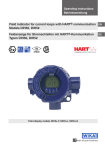
Field display
models DIH50-F, DIH52-F
Field display
model DIH62-F
GB Operating instructions
Models DIH50, DIH52, DIH62
Page
3 - 46
D Betriebsanleitung
Typen DIH50, DIH52, DIH62
Seite
47 - 85
Prior to starting any work, read the operating instructions!
Keep for later use!
Vor Beginn aller Arbeiten Betriebsanleitung lesen!
Zum späteren Gebrauch aufbewahren!
2
WIKA operating instructions models DIH50, DIH52, DIH62
14008548.01 05/2011 GB/D
© 2011 WIKA Alexander Wiegand SE & Co. KG
All rights reserved. / Alle Rechte vorbehalten.
WIKA® is a registered trademark in various countries.
WIKA® ist eine geschützte Marke in verschiedenen Ländern.
Contents
Contents
1. General information
2. Safety
3. Specifications
4. Design and function
5. Transport, packaging and storage
6. Commissioning, operation
7. Electrical connection
8. Menu guidance
9. Information on mounting and operation in
hazardous areas
10. Maintenance and cleaning
11. Faults
12. Dismounting, return and disposal
Appendix 1: FM/CSA installation drawing
14008548.01 05/2011 GB/D
Appendix 2: EC type-examination certificate
Appendix 3: IECEx certificate of conformity
Appendix 4: EC declaration of conformity
4
5
11
12
16
16
20
24
31
35
36
37
39
40
42
46
Declarations of conformity can be found online at www.wika.com.
WIKA operating instructions models DIH50, DIH52, DIH62
3
GB
1. General information
1. General information
■■ The field displays described in the operating instructions have been
designed and manufactured using state-of-the-art technology. All
components are subject to stringent quality and environmental
criteria during production. Our management systems are certified
to ISO 9001 and ISO 14001.
GB
■■ These operating instructions contain important information on
handling the field display. Working safely requires that all safety
instructions and work instructions are observed.
■■ Observe the relevant local accident prevention regulations and
general safety regulations for the field display’s range of use.
■■ The operating instructions are part of the product and must be
kept in the immediate vicinity of the field instrument and readily
accessible to skilled personnel at any time.
■■ Skilled personnel must have carefully read and understood the
operating instructions prior to beginning any work.
■■ The manufacturer’s liability is void in the case of any damage
caused by using the product contrary to its intended use,
non-compliance with these operating instructions, assignment
of insufficiently qualified skilled personnel or unauthorised
modifications to the field displays.
■■ The general terms and conditions contained in the sales documen-
tation shall apply.
■■ Further information:
- Internet address:
- Relevant data sheet:
- Application consultant:
4
www.wika.de / www.wika.com
AC 80.10
Tel.:
(+49) 9372/132-0
Fax:
(+49) 9372/132-406
E-Mail: [email protected]
WIKA operating instructions models DIH50, DIH52, DIH62
14008548.01 05/2011 GB/D
■■ Subject to technical modifications.
1. General information / 2. Safety
Explanation of symbols
WARNING!
... indicates a potentially dangerous situation that can
result in serious injury or death, if not avoided.
GB
CAUTION!
... indicates a potentially dangerous situation that can
result in light injuries or damage to equipment or the
environment, if not avoided.
Information
… points out useful tips, recommendations and information for efficient and trouble-free operation.
DANGER!
...identifies hazards caused by electrical power. Should
the safety instructions not be observed, there is a risk of
serious or fatal injury.
WARNING!
... indicates a potentially dangerous situation in the
hazardous area that can result in serious injury or death,
if not avoided.
14008548.01 05/2011 GB/D
2. Safety
WARNING!
Before mounting, commissioning and operation, make
sure that the display is suitable for the application.
Non-observance can result in serious injury and/or
damage to the equipment.
WIKA operating instructions models DIH50, DIH52, DIH62
5
2. Safety
WARNING!
This is protection class 3 equipment for connection at low
voltages, which are separated from the power supply or
voltage by greater than AC 50 V or DC 120 V. Preferably,
a connection to an SELV or PELV circuit is recommended;
alternatively protective measures from HD 60346-4-41
(DIN VDE 0100-410).
GB
Alternatively for North America:
the connection can be made in line with "Class 2 Circuits"
or "Class 2 Power Units" in accordance with CEC (Canadian Electrical Code) or NEC (National Electrical Code).
Further important safety instructions can be found in the
individual chapters of these operating instructions.
2.1 Intended use
The field display models DIH50, DIH52 and DIH62 are used for
converting an analogue current signal (4 … 20 mA) into an indication
of the corresponding measured value and are intended for mounting
in the field.
They comprise a display and operating unit without power supply for
looping in 4 … 20 mA/HART® circuits.
The technical specifications contained in these operating instructions must be observed. Improper handling or operation of the field
display outside of its technical specifications requires the instrument
to be taken out of service immediately and inspected by an authorised
WIKA service engineer.
If the field displays are transported from a cold into a warm
environment, condensate formation may lead to deficiency of the
instrument functionality. Before putting it back into operation, wait for
the instrument temperature and the room temperature to equalise.
6
WIKA operating instructions models DIH50, DIH52, DIH62
14008548.01 05/2011 GB/D
The field display has been designed and built solely for the intended
use described here, and may only be used accordingly.
2. Safety
The manufacturer shall not be liable for claims of any type based on
operation contrary to the intended use.
2.2 Personnel qualification
WARNING!
Risk of injury if qualification is insufficient!
Improper handling can result in considerable injury and
damage to equipment.
■■ The activities described in these operating instructions
may only be carried out by skilled personnel who have
the qualifications described below.
■■ Keep unqualified personnel away from hazardous
areas.
Skilled personnel
Skilled personnel are understood to be personnel who, based on their
technical training, knowledge of measurement and control technology
and on their experience and knowledge of country-specific regulations, current standards and directives, are capable of carrying out the
work described and independently recognising potential hazards.
Special operating conditions require further appropriate knowledge,
e.g. of aggressive media.
14008548.01 05/2011 GB/D
2.3 Additional safety instructions for instruments with ATEX
approval
WARNING!
Non-observance of these instructions and their contents
may result in the loss of explosion protection.
WARNING!
Do not use transmitters with any damage to the exterior!
WIKA operating instructions models DIH50, DIH52, DIH62
7
GB
2. Safety
CAUTION!
■■ Repairs are strictly prohibited.
■■ Do not use displays presenting externally visible
damage.
■■ Observe the instructions for mounting and operation as
well as the requirements for the use of the devices in
hazardous areas.
GB
2.4 Special hazards
WARNING!
Observe the information given in the applicable type
examination certificate and the relevant country-specific
regulations for installation and use in potentially explosive atmospheres (e.g. EN/IEC 60079-14, NEC, CEC).
Non-observance can result in serious injury and/or
damage to the equipment.
For additional important safety instructions for insturments
with ATEX approval see chapter "9. Notes for mounting
and operating in hazardous areas".
WARNING!
To ensure safe working on the instrument, the operating
company must ensure
■■ that suitable first-aid equipment is available and aid is
provided whenever required,
■■ that the operating personnel are regularly instructed in all
topics regarding work safety, first aid and environmental
protection and knows the operating instructions and, in
particular, the safety instructions contained therein.
8
WIKA operating instructions models DIH50, DIH52, DIH62
14008548.01 05/2011 GB/D
WARNING!
For hazardous media such as oxygen, acetylene, flammable or toxic gases or liquids, and refrigeration plants,
compressors, etc., in addition to all standard regulations,
the appropriate existing codes or regulations must also be
followed.
2. Safety
WARNING!
When working during a running process operation,
measures to prevent electrostatic discharge from the
connecting terminals should be taken, as a discharge
could lead to temporary corruption of the measured value.
DANGER!
Danger of death caused by electric current
Upon contact with live parts, there is a direct danger of
death.
■■ Electrical instruments may only be installed and
connected by skilled electrical personnel.
■■ Operation using a defective power supply unit (e.g.
short circuit from the mains voltage to the output
voltage) can result in life-threatening voltages at the
instrument!
WARNING!
Residual media in dismounted instruments can result in
a risk to persons, the environment and equipment. Take
sufficient precautionary measures.
2.5 Labelling / safety marks
14008548.01 05/2011 GB/D
Product label
Model
01/2011
For an explanation
of symbols, see
page 10
Year of
manufacture
WIKA operating instructions models DIH50, DIH52, DIH62
9
GB
2. Safety
■■ Product label for model DIH50-B
For an explanation of
symbols, see below
GB
Explanation of symbols
Before mounting and commissioning the instrument, ensure you read the operating instructions!
CSA, Canadian Standard Association®
The instrument has been inspected and certified by CSA
International. Instruments bearing this mark comply with
the applicable Canadian standards on safety (including
explosion protection).
CE, Communauté Européenne
Instruments bearing this mark comply with the relevant
european directives.
FM, Factory Mutual
The instrument was inspected and certified by FM
Approvals. Instruments bearing this mark comply with the
applicable US standards on safety (including explosion
protection).
10
WIKA operating instructions models DIH50, DIH52, DIH62
14008548.01 05/2011 GB/D
ATEX European Explosion Protection Directive
(Atmosphère = AT, explosible = EX)
Instruments bearing this mark comply with the requirements of the European Directive 94/9/EC (ATEX) on
explosion protection.
3. Specifications
3. Specifications
Specifications
14008548.01 05/2011 GB/D
■■ Principle
■■ Measured value
Model DIH50 Models DIH52, DIH62
LCD, rotatable in 10° steps
7-segment LCD, 5-digit, character size 9 mm
■■ Bar graph
20-segment LCD
■■ Information line
14-segment LCD, 6-digit, character size 5.5 mm
■■ Status indicators
♥
: HART® mode (signalling of HART®
parameter adoption)
: Unit lock
: Warnings or error messages
■■ Scale range
-9999 ... 99999
Measuring rate
4/s
Accuracy
± 0.1 % of the
± 0.05 % of the measuring span
measuring span
Temperature coefficient ± 0.1 % of the measuring span / 10 K
Permitted current
100 mA
carrying capacity
Voltage drop
< DC 3 V (< DC 2 V at 20 mA); supply via current loop
HART® functionality
■■ Access control
Secondary master
■■ Automatically set
Unit, measuring range
parameters
■■ Available
Unit, measuring range start/end,
commands
format, zero point, span, damping,
polling address
■■ Identified
Generic mode: Generic mode:
commands
1, 15, 35, 44
0, 1, 6, 15, 34, 35, 36, 37, 44
■■ Multidrop
not supported
Measured values are automatically
taken from the HART® digital data
and displayed
Operating
■■ Ambient temperature -20 ... +85 °C
-20 ... +70 °C
■■ Vibration resistance 3 g per EN 60068-2-6
■■ Shock resistance
30 g per EN 60068-2-27
CE conformity
■■ EMC directive
2004/108/EC, EN 61326 emission (group 1, class B)
and interference immunity (industrial application)
WIKA operating instructions models DIH50, DIH52, DIH62
11
GB
3. Specifications / 4. Design and function
Models DIH50, DIH52
Model DIH62
Material
Aluminium, window in
polycarbonate
Colour
Night blue, RAL 5022
Cable glands
Ingress protection
Weight
Dimensions
3 x M20 x 1.5 or 3 x ½ NPT
IP 66
approx. 1.5 kg
see drawing
Aluminium, plastic,
stainless steel, window
from polycarbonate
Night blue, RAL 5022
(aluminium, plastic)/silver
(stainless steel)
Basic module
Models DIH50-B, DIH52-B, DIH62-B
Material
Weight
Dimensions
Polycarbonate
approx. 80 g
see drawing
For further specifications see WIKA data sheet AC 80.10 and the order
documentation.
For further important safety instructions for operation in
hazardous areas see chapter "9. Notes for mounting and
operating in hazardous areas".
4. Design and function
4.1 Description
The field displays model DIHxx are external display and operating
units without separate power supply for 4 … 20 mA/HART® sensors.
They are used for measuring value display and operation remote from
the measuring point.
They are looped anywhere in the 4 … 20 mA signal line and measure
the current in the current loop. At the same time, they read and display
the measured values with unit via the HART® signal.
12
WIKA operating instructions models DIH50, DIH52, DIH62
14008548.01 05/2011 GB/D
GB
Field case
4. Design and function
The field displays are powered directly from the 4 ... 20 mA current
loop, with a resultant voltage drop of less than 3 V.
The field displays meet the requirements of:
■■ Explosion protection (depending on the version)
■■ Electromagnetic compatibility in accordance with DIN EN 61326
GB
and NAMUR recommendation NE21
Versions
Model DIHxx-B
Model DIH5x-F
Model DIHxx-I
Model DIHxx-S
Model DIHx0
Model DIHx2
Basic module without field case
Field display, Ex protection (Flameproof enclosure)
Field display, Ex protection (intrinsically safe)
Field display, no Ex protection (standard)
HART®-slave (standard)
HART®-master
14008548.01 05/2011 GB/D
1920741.01
4.1.1 Basic module (DIH50-B, DIH52-B)
The basic modules comprise a mounting adapter with two integrated
connection terminals and connecting cables, as well as a display unit
including the display and the electronics. Both parts are connected
via a cable with plug-in coupling. Depending on their design, the
basic modules can be mounted in different cases or thermometer
connection heads.
WIKA operating instructions models DIH50, DIH52, DIH62
13
4. Design and function
4.1.2 Field displays (DIH5x-S, DIH5x-I, DIH5x-F, DIH62-S, DIH62-I)
The field cases comprise a case with integrated display and operation
module and a terminal insert with two terminal blocks.
■■ Field display, models DIH50, DIH52
14008548.01 05/2011 GB/D
1556707.01
GB
Use cases suitable for field mounting which comply with the valid
regulations and requirements. In particular, observe the ambient
conditions defined in chapter "3. Specifications" and the requirements
defined in chapter "9. Information on mounting and operation in
hazardous areas".
14
WIKA operating instructions models DIH50, DIH52, DIH62
4. Design and function
14008548.01 05/2011 GB/D
Single chamber housing,
deep-drawn stainless steel
02231993
Single chamber housing, aluminium
or cast stainless steel
02231961
Single chamber housing,
plastic
02231918
■■ Field display model DIH62
4.2 Scope of delivery
Cross-check scope of delivery with the delivery note.
WIKA operating instructions models DIH50, DIH52, DIH62
15
GB
5. Transport, packaging ... / 6. Commissioning ...
5. Transport, packaging and storage
5.1 Transport
Check the instrument for any damage that may have been caused
GB during transportation.
Obvious damage must be reported immediately.
5.2 Packaging
Do not remove packaging until just before mounting.
Keep the packaging as it will provide optimum protection during transport (e.g. change in installation site, sending for repair).
5.3 Storage
Permissible conditions at the place of storage:
■■ Storage temperature: -40 ... +85 °C
■■ Humidity: 35 ... 85 % relative humidity (without condensation)
Avoid exposure to the following factors:
■■ Direct sunlight or proximity to hot objects
■■ Mechanical vibration, mechanical shock (putting it down hard)
■■ Soot, vapour, dust and corrosive gases
6. Commissioning, operation
6.1 Operating modes
The following operating modes are possible:
■■ HART®-slave / basic mode (4 ... 20 mA)
■■ HART®-master / basic mode / multidrop (models DIH52, DIH62)
16
WIKA operating instructions models DIH50, DIH52, DIH62
14008548.01 05/2011 GB/D
In hazardous areas, only use field displays that are
approved for those hazardous areas. The approval is
marked on the product label.
6. Commissioning, operation
6.1.1 Operating mode: HART®-slave (models DIH50, DIH52, DIH62)
The digital indicators powered via the same current loop as the
corresponding transmitters monitor permanently the HART®
communication. When modifying the unit or measuring range of
the connected transmitter, the unit of the digital indicator and the
GB
corresponding scale range are adapted automatically.
However, it is required that the unit set in the transmitter is also set in
the devices.
A flashing ♥ symbol is shown on the display when a HART®
communication takes place for the first time and the digital indicators
are thus switched to the HART® mode. The ♥ symbol is displayed
permanently when the HART® communication is terminated and the
digital indicator is configured according to the measuring range and
the unit of the connected transmitter.
After the power supply was interrupted or the digital indicator was set
manually, the ♥ symbol is no longer displayed.
During operation in the basic mode, the ♥ symbol is not displayed.
14008548.01 05/2011 GB/D
CAUTION!
The devices react only to the HART® standard commands
15 and 35. If a connected HART® transmitter is configured
by means of other commands, automatic setting is not
possible!
The HART® function, i.e. the automatic adaptation of the
display to the configured data of the transmitter, requires
a HART® communication between the transmitter and
the HART® software (e.g. WIKA_T32) or between the
transmitter and the field communicator (e.g. FC375/
FC475, MFC4150 etc.).
WIKA operating instructions models DIH50, DIH52, DIH62
17
6. Commissioning, operation
During the starting procedure, the field displays try to contact the
connected HART® transmitter in the master mode and to apply
its settings (unit and measuring range). During the connection
establishment, the status line shows the message "Connecting
HART®".
When a HART® sensor is detected, the HART® symbol is displayed.
The field display switches to the HART® mode and starts operation
using the settings received from the transmitter. This procedure is
repeated whenever the power supply is switched on.
When pressing any key during the starting process or the device has
not detected any HART® transmitter during approx. 70 seconds, the
digital indicator switches to the basic mode and starts operation on the
basis of the factory settings.
6.1.3 Operating mode: Multidrop (models DIH52, DIH62)
In this specially defined operating state for HART® transmitters, the
current signal is firmly set to 4 mA and the measuring information
is transmitted via the HART® communication to the control room.
To enable the displaying of the measured value of a transmitter, the
address of the desired transmitter must be set in the "Address" menu
item.
If the HART® address is modified during operation, the establishment
of a new connection is started during which, however, the sensor
must respond immediately in order to complete the connection
establishment.
18
WIKA operating instructions models DIH50, DIH52, DIH62
14008548.01 05/2011 GB/D
GB
6.1.2 Operating mode: HART® master (models DIH52, DIH62)
The master mode enables the modification of the measuring range,
the unit, the format, the damping and the polling address of the
connected HART® transmitter. Further modifications to the configuration of the transmitter (e.g. selection of the sensor) are not possible.
6. Commissioning, operation
The digital indicators show the measured values of the primary variable transmitted via HART® to the control room. The display is passive,
i.e. the transmission of the measured values must be requested by the
control room. The devices function as secondary master with respect
to the sensor during the parameterisation.
6.1.4 Operating mode: Basic mode, 4 ... 20 mA (DIH50, DIH52, DIH62)
In the basic mode, all settings of the digital indicator must be carried
out manually by means of the front-side keys.
To navigate in the menu levels, four keys with the following functions
are available:
▲ (UP)
▼ (DOWN)
SELECT
BACK
One menu item up
One menu item down
Calls the programming menu
Exits the programming menu
- Back to the previous menu level in the menu guidance
- Return from the edit function without saving the
modification
see also chapter "8. Menu guidance"
6.2 User interface
Models DIH50, DIH52
Model DIH62
Status data
Unit / info line
Measured value
14008548.01 05/2011 GB/D
Bar graph
Operating keys
WIKA operating instructions models DIH50, DIH52, DIH62
19
GB
7. Electrical connection
7. Electrical connection
WARNING!
Observe the safety-relevant maximum values for the
connection of the power supply and the sensors defined in
chapter "9.1 Model overview and their approvals".
GB
When working on the field displays (e.g. installation/removal,
maintenance work) take measures to prevent electrostatic discharge
from the terminals.
WARNING!
Carry out mounting work only with power disconnected!
Use the recommended cables and tighten the cable gland. Lead
the connecting cable downward before of the cable gland in order
to provide additional protection of the device against penetration of
liquids. Rain water and condensed water can thus drip.
Connect the cable screen on both sides to earth potential if a
screened cable is required. Connect the screen in the sensor directly
to the internal earth terminal. The external earth terminal of the case
must be connected with low impedance to the equipotential bonding.
20
WIKA operating instructions models DIH50, DIH52, DIH62
14008548.01 05/2011 GB/D
The device is connected by means of a commercially available
two-wire cable without screen. If electromagnetic interference
exceeding the test values of EN 61326 for industrial areas is to be
expected or the HART® multidrop mode is used, a screened cable
must be used. Use cables with round cross-section. An outside
diameter of cable between 5 and 9 mm (0.2 … 0.35 inch) guarantees
the tightness of the cable gland. When using other diameters or crosssections, the gasket must be replaced or a suitable cable gland must
be used.
7. Electrical connection
CAUTION!
If equipotential bonding currents are to be expected, a
ceramic capacitor (e.g. 1 nF, 1500 V) must be used for
the connection on the evaluation side. The low-frequency
equipotential bonding currents are thus suppressed, but
the high-frequency interference signals remain.
7.1 Field displays models DIH50, DIH52
Open the case cover, push one of the two black fastening clips
backwards and pull the display module upwards. The power supply
is connected at the front via the Philips screws of the display module.
Connect the positive pole of the power supply to the terminal marked
with ⊕ and the negative pole of the power supply to the terminal
marked with ⊖.
The signal line of the transmitter is to be connected to the terminal
blocks inside the field case. To do so, connect the positive pole of the
signal line to the terminal marked with ⊕ (red cable) and the negative
pole of the signal line to the terminal marked with ⊖ (black cable).
With flexible leads we recommend the use of crimped connector
sleeves.
Not Ex area
Power supply
Hazardous area
DIH50, DIH52
red
spring-loaded
push terminals
Transmitter
14008548.01 05/2011 GB/D
black
Consumers
WIKA operating instructions models DIH50, DIH52, DIH62
21
GB
7. Electrical connection
The integrated reverse polarity
protection (wrong polarity on the
terminals ⊕ and ⊖) prevents the
digital indicator from damage.
GB The following maximum values are
applicable:
without explosion protection: 42 V
with explosion protection: 30 V
The connected wires must be checked to ensure they are connected
properly. Only well-secured wires can guarantee a fault-free operation.
Recommended tools for terminal screws:
Model
DIH50,
DIH52
Screwdriver
Cross head ('Pozidriv' tip)
size 2 (ISO 8764)
Tightening torque
0.4 Nm
Note:
Fixed wires as well as flexible wires with end splices are inserted
directly into the terminal openings. In the case of flexible wires without
end splice, press with a slotted screwdriver the terminal to release the
terminal opening. By loosening the slotted screwdriver, the terminals
are closed again.
22
WIKA operating instructions models DIH50, DIH52, DIH62
14008548.01 05/2011 GB/D
7.2 Field display model DIH62
Open the case cover and remove the display and operation module
by slightly turning it to the left. Loosen the cable gland. Strip the
signal lines approx. 10 cm and strip the insulation of the wire ends
approx. 1 cm. Connect the wire ends to the terminals according to the
connection diagram.
7. Electrical connection
Not Ex area
Hazardous area
Power supply
GB
Transmitter
1 Connection of the transmitter: Connect the positive pole of the transmitter to the
terminal marked with ⊕ (1) and the negative pole of the transmitter to the terminal
marked with ⊖ (2).
2 Connection of the power supply: Connect the positive pole of the power supply
to the terminal marked with ⊕ (3) and the negative pole of the power supply to
the terminal marked with ⊖ (4).
3 Connection of the display module: Put the display module connector accurately
(coded!) on the mating connector and press it down.
Check the correct fit by slight pulling.
Connect the screen to the internal earth terminal and the external
earth terminal to the equipotential bonding.
Put on the display and operation module and turn slightly to the right.
Tighten the cable gland and mount the case cover.
14008548.01 05/2011 GB/D
Note:
The terminal block is pluggable and can be pulled off
from the electronics. To do so, lift the terminal block
using a small screwdriver and pull it out. When plugging
it again, it must engage with an audible click.
CAUTION!
When connecting an EN/IEC certified transmitter, please
observe the corresponding operating instructions and the
requirements relating to the transmitter.
WIKA operating instructions models DIH50, DIH52, DIH62
23
8. Menu guidance
8. Menu guidance
Submenu 1
Measurement
Unit
Submenu 2
Measuring range start
Measuring range end
Measuring range format
Display
Unit
Unit lock
Display format
Filter
Alarm
on/off
Low alarm
High alarm
Min/Max memory
delete
display yes/no
Configuration
Language
Contrast
Reset
User unit
Min. failure message
Max. failure message
Firmware version
24
WIKA operating instructions models DIH50, DIH52, DIH62
14008548.01 05/2011 GB/D
GB
Main menu
8. Menu guidance
8.1 Main menu "Measurement"
Function
Unit
Setting the unit of the measuring range of the connected
transmitter
Setting range:
mA → Ohm → bar → mbar → PSI → hPa → kPa → mmH2O
→ mH2O → inHG → °C → °F → K → % → USER → V
Measuring range start
Setting of the start value of the measuring range of the
connected transmitter (e.g. -30 for a measuring range of
-30 ... +120 °C)
Setting range: -9999 ... 99999
Measuring range end
Setting the end value of the measuring range of the
connected transmitter (e.g. 120 for a measuring range of
-30 ... +120 °C)
14008548.01 05/2011 GB/D
Setting range: -9999 ... 99999
Measuring range format
Setting the decimal point for the measuring range of the
connected transmitter.
GB
Factory
setting
mA
4.000
20.000
0.000
Setting range: 0 ↔ 0.0 ↔ 0.00 ↔ 0.000 ↔ 0.0000
Span (only DIH52, DIH62)
The current measured value is applied as max. adjustment
for the sensor.
Attention: Cannot be used for all HART® transmitters
Zero point (only DIH52, DIH62)
The current measured value is applied as min. adjustment
for the sensor.
Attention: Cannot be used for all HART® transmitters
WIKA operating instructions models DIH50, DIH52, DIH62
25
8. Menu guidance
Damping (only DIH52, DIH62)
Input damping for damping the measured value.
Setting range: 0.0 … 999
Adress (only DIH52, DIH62)
GB Setting the HART® address of the assigned transmitter in
the multidrop mode; for the standard current loop mode,
this address must always be set to 0.
Setting range: 0 ... 15
8.2 Main menu "Display"
Factory
setting
Unit
mA
Setting the unit for the display of the digital indicator
Here, you can select a unit deviating from the unit of
the measuring range of the connected transmitter. The
measured values are then converted automatically into
the deviating unit.
However, only units of the same unit group as the set unit
of the measuring range may be selected.
Setting range (according to unit groups):
- Electr. measurement parameters: V, mA, Ohm
- Pressure: bar, mbar, PSI, hPa, kPa, mmH2O, mH2O, inHG
- Temperature: °C, °F, K
- Others: %, USER
26
WIKA operating instructions models DIH50, DIH52, DIH62
14008548.01 05/2011 GB/D
Function
8. Menu guidance
Unit lock
UnLoC
By activating the unit lock, the set display unit is locked to
protect the unit against modifications. The display shows
the sign
. Modifications of the measuring range are
converted automatically.
The unit lock only functions if the units of the measuring
range and the display originate from the same unit group.
When connecting a transmitter and its configuration via
HART® with a unit of another unit group, then the unit lock
is deactivated. In this case, the display unit is set according
to the configured measuring range unit.
Setting range:
- not locked (UnLoC)
- locked (LoC)
Scale range format
Setting the decimal point for the scale range of the digital
indicator
Setting range: 0 ↔ 0.0 ↔ 0.00 ↔ 0.000 ↔ 0.0000
Filter
Activation of the digital filter of the 1st order;
Setting range: 0 ... 10
Alarm
From this menu item it is possible to branch into the
submenu 2 for the alarm configuration by selecting
SELECT.
0.000
0
-----
-----
14008548.01 05/2011 GB/D
Min/Max memory
From this menu item it is possible to branch into the
submenu 2 for the min./max. memory by selecting
SELECT.
GB
WIKA operating instructions models DIH50, DIH52, DIH62
27
8. Menu guidance
8.2.1 Submenu "Alarm"
Function
Factory
setting
on/off
OFF
Activating or deactivating the alarm function;
if a value exceeds or falls below a set alarm limit, the
display shows the warning symbol
and the measured
value starts flashing.
Setting range:
- OFF
- ON
Low alarm
4.000
Setting the value which releases the alarm function when
this value is not reached.
Setting range:
Start value of the scale range up to the set value of the
high alarm
High alarm
20.000
Setting the value upon exceeding of which the alarm
function is released.
Setting range:
Set value of the low alarm up to the end value of the scale
range
14008548.01 05/2011 GB/D
GB
28
WIKA operating instructions models DIH50, DIH52, DIH62
8. Menu guidance
8.2.2 Submenu "Min/Max memory"
Function
Delete min/max
Function for deleting the maximal value memory
Pressing the SELECT key twice deletes the maximum
value memory.
dEL
OFF
14008548.01 05/2011 GB/D
min/max on/off
Activation of the min./max. display;
if the min./max. display is switched on, the display
switches cyclically between the current measured value
(display time 5 s), the minimum value and the maximum
value (display time 2 s).
For the display of the maximum values, the unit on the
display is replaced by min. or max.
Setting range:
- OFF
- ON
GB
Factory
setting
WIKA operating instructions models DIH50, DIH52, DIH62
29
8. Menu guidance
8.3 Main menu "Configuration"
Function
Language
Setting the language
Setting range:
- dEU (GEr): German
- EnG:
English
Contrast
Setting range:
1-4
Reset
A reset is used to reset all settings of the digital indicator
to the factory settings.
The SELECT key must be pressed twice to activate the
reset.
After pressing the key once, the RESET display starts
flashing and after the second actuation of the key, the
display is completely hidden and the reset is carried out.
USER-unit
The user can freely program a 6-digit user unit.
The 6 characters can be selected from an alphanumeric
character set.
By pressing the SELECT key, the first digit is enabled
and starts flashing. Use the arrow keys to select the
desired character. By pressing the SELECT key again, the
character is confirmed and the next digit is enabled.
30
Factory
setting
EnG
2
-----
USER
WIKA operating instructions models DIH50, DIH52, DIH62
14008548.01 05/2011 GB/D
GB
8. Menu guidance / 9. Information on ...
Min. failure message
Setting the current value which releases the min. failure
message when this value is reached or not reached.
The min. failure message is displayed with 5 underscores
(_ _ _ _ _) and the message OUTMIN.
3.6
GB
Setting range: 3.5 ... 3.9 mA
21.0
Max. failure message
Setting the current value upon reaching or exceeding of
which the max. failure message is released.
The
max.
___
_ _ failure message is displayed with 5 upper scores
(
) and the message OUTMAX.
Setting range: 20.1 ... 21.5 mA
Firmware version
The number of the firmware version used is displayed.
9. Information on mounting and operation in
hazardous areas
In hazardous areas, only use field displays that are approved for those
hazardous areas. The approval is marked on the product label.
14008548.01 05/2011 GB/D
When connecting them to other devices or component, observe the
connection requirements regarding explosion protection, such as
maximum admissible voltage, power or load with capacitances (see
chapter 9.2 to 9.4).
WIKA operating instructions models DIH50, DIH52, DIH62
31
9. Information on mounting and operation ...
9.1 Model overview and their approvals
Model
Ex protection and
Approval No.
DIH50-B
GB DIH52-B
DIH62-B
DIH50-F
DIH52-F
DIH50-B
DIH52-B
DIH50-I,
DIH52-I,
DIH62-I
II 1G Ex ia IIC T4/T5/T6 Ga
II (1) 2G Ex ia 2c T4/T5/T6 (Ga) Gb
II 1D Ex ia IIIC T120°C Da
II (1) 2D Ex ia IIIC T120°C (Da) Db
BVS 10 ATEX E 016 X
IECEx BVS 10.0037X
II 2G Ex d IIC T6/T5/T4 Gb
II 2G Ex db IIC T6/T5/T4
Ex d IIC T6/T5/T4 Gb
Ex db IIC T6/T5/T4
BVS 10 ATEX E 158
IECEx BVS 10.0103
CSA (1946893 (LR 66027)
Class I, Division 1 + 2, Groups A, B, C, D
FM (3031500)
Class I, Division 1, Groups A, B, C, D
(IS/I/1/ABCD/T* + IS/I/0AEx ia/IIC/T*)
Ignition
protection type
intrinsically safe
equipment
Flameproof
enclosure
intrinsically safe
equipment
Class I, Division 2, Groups A, B, C, D
NI/I/2/ABCD/T* + NI/I/2/IIC/T*
Approval pending
9.2 Specific conditions for safe use models DIH50-B, DIH52-B
■■ The digital indicator comprises one or two mechanical components:
■■ Installation outside hazardous areas:
- The digital indicator for current loops model DIHxx-B must be built
in a case which guarantees at least the degree of protection IP 20
according to EN 60529.
- The wiring in this case must meet the requirements of Sections
6. 3.11 and 7. 6.e EN 60079-11:2007.
32
WIKA operating instructions models DIH50, DIH52, DIH62
14008548.01 05/2011 GB/D
- Display assembly model DIH5x-B / DIH62-B
- Adapter assembly model DIH5x-NT / DIH62-NT
9. Information on mounting and operation ...
- Terminals or connectors of intrinsically safe circuits must
be designed in accordance with Section 6.2.1 or 6.2.2 of
EN 60 079-11:2007.
■■ Installation in areas subject to EPL Gb requirements
GB
(Module marking: II (1) 2G Ex ia IIC T4 I T5 I T6 (Ga) Gb):
- Due to the application, the digital indicator for current loops model
DIHxx-B must be built in a case which is suitable for mounting in
areas subject to EPL Gb requirements and guarantees at least the
degree of protection IP 20 according to EN 60529.
- The wiring in this case must meet the requirements of Sections 6.
3.11 and 7. 6.e EN 60079-11: 2007.
- Terminals or connectors of intrinsically safe circuits must
be designed in accordance with Section 6.2.1 or 6.2.2 of
EN 60079-11:2007.
■■ Installation in areas subject to EPL Ga requirements
(Module marking: II 1G Ex ia IIC T4 I T5 I T6 Ga):
- Due to the application, the digital indicator for current loops
model DIHxx-B must be built in a case which is suitable for
mounting in areas subject to EPL Ga requirements and guarantees
at least the degree of protection IP 54 according to EN 60529 and
in the inside of which electrostatic charges are impossible.
14008548.01 05/2011 GB/D
■■ Installation in areas subject to EPL Db, Da requirements
(Module marking: II 1D Ex ia IIIC T120 °C Da or II (1) 20 Ex ia IIIC
T120 °C (Da) Ob):
- Due to the application, the digital indicator for current loops
model DIHxx-B must be built in a case which is suitable for mounting
in areas subject to EPL Db, Da requirements and guarantees at
least the degree of protection IP 6x according to EN 60529.
- The wiring in this case must meet the requirements of Sections
6.2.4 and 7.6 EN 61241-11:2006.
- Terminals or connectors of intrinsically safe circuits must
be designed in accordance with Section 6.3.1 or 6.3.2 of
EN 61241-11: 2006.
WIKA operating instructions models DIH50, DIH52, DIH62
33
9. Information on mounting and operation ...
Intrinsically safe supply and signal circuit
(4 ... 20 mA loop; terminal ⊕ and ⊖)
Parameters
Model DIH50
29 V
100 mA
660 mW
12 nF
2.2 μH
Models DIH52, DIH62
29 V
27.5 V 26 V
100 mA 115 mA 131 mA
680 mW
12 nF
2.2 μH
According to the temperature class, these field displays may only be
used in the following ambient temperature ranges:
Application Ambient
Temperature Power Pi
temperature range class
DIH50
DIH52, DIH62
Group II
-40 °C ≤ Ta ≤ +85 °C
-40 °C ≤ Ta ≤ +75 °C
-40 °C ≤ Ta ≤ +55 °C
-40 °C ≤ Ta ≤ +70 °C
-40 °C ≤ Ta ≤ +40 °C
Dust Ex
T4
T5
T6
N/A
N/A
<660 mW
<660 mW
<660 mW
<630 mW
<660 mW
<680 mW
<680 mW
<680 mW
<650 mW
<680 mW
N / A = not applicable
9. 3 Specific conditions for safe use models DIH50-F, DIH52-F
Cables, insertions and blind plugs must be suitable for the
corresponding operating temperature. You must therefore check in
the application case (e.g. ambient temperature plus 5 K) whether the
components used are suitable. The devices may not be opened while
they are under voltage.
Observe the warnings on the devices:
"WARNING! – Do not open while under voltage"
34
WIKA operating instructions models DIH50, DIH52, DIH62
14008548.01 05/2011 GB/D
GB
Voltage Ui /U0
Strenght of current Ii/I0
Power Pi
Effective internal capacitance Ci
Effective internal inductance Li
9. Information on ... / 10. Maintenance, cleaning
9.4 Specific conditions for safe use model DIH62-I (plastic case)
The device is not suitable for zone 0.
Electrostatic charges must be avoided when cleaning the device.
The surfaces of the plastic case are not conductive. The field display
must be installed in a way to prevent any electrostatic charges.
10. Maintenance and cleaning
10.1 Maintenance
The field displays described here are maintenance-free.
The electronics are completely encapsulated and incorporate no
components which could be repaired or replaced.
Repairs must only be carried out by the manufacturer.
10.2 Cleaning
14008548.01 05/2011 GB/D
CAUTION!
■■ Prior to cleaning, switch off and disconnect the
instrument from the mains.
■■ Clean the instrument with a moist cloth.
■■ Electrical connections must not come into contact with
moisture.
■■ Wash or clean the dismounted instrument before
returning it in order to protect personnel and the
environment from exposure to residual media.
For information on returning the instrument see chapter
"12.2 Returns".
WIKA operating instructions models DIH50, DIH52, DIH62
35
GB
11. Faults
11. Faults
Fault-tree
Current loop disconnected
l = 0 mA
Transmitter not connected
Power supply connected incorrectly
(wrong polarity)
l > 20 mA
Process temperature out of range
l < 4 mA
Sensor break or short circuit
Sensor connected incorrectly
4 mA < l < 20 mA
but wrong values
Wrong transmitter configuration
Error messages
HART® communication errors are reported by means of the numeric
codes 1 - 9. An error message is shown if a transaction was not
successful after several repetitions. An error message is only
displayed if an error occurs as a result of a command sent by the
display, i.e. only if the error is due to a user operation. Errors in the
communication between the control room and the sensor are detected
but not displayed.
The measuring value line shows “Error”, the status line shows
“HART® n” whereby “n” represents the numeric error code. The error
message remains displayed until the next key actuation takes place.
36
WIKA operating instructions models DIH50, DIH52, DIH62
14008548.01 05/2011 GB/D
GB
11. Faults
The following table shows the error codes and information regarding
the failure cause and elimination.
Error code Description
Reason
1
2
3
4
5
Transmitter does not
respond
Communication error ■■ Parity, check sum, package
length incorrect upon receiving
■■ Transmitter signals receive error
Command not
Command not supported by the
implemented
transmitter
■■ The value is outside the range
Range error
supported by the sensor
■■ The desired unit of measure is
not supported
Unspecified error of
The sensor signals an error in the
the transmitter
status byte that is not broken down
14008548.01 05/2011 GB/D
CAUTION!
If faults cannot be eliminated by means of the measures
listed above, the instrument must be shut down
immediately, and it must be ensured that signal is no
longer present, and it must be prevented from being
inadvertently put back into service.
In this case, contact the manufacturer.
If a return is needed, please follow the instructions given in
chapter "12.1 Return".
12. Dismounting, return and disposal
WARNING!
Residual media in dismounted instruments can result in a
risk to persons, the environment and equipment.
Take sufficient precautionary measures.
WIKA operating instructions models DIH50, DIH52, DIH62
37
GB
12. Dismounting, return and disposal
12.1 Return
WARNING!
Absolutely observe the following when shipping the
instrument:
All instruments delivered to WIKA must be free from any
kind of hazardous substances (acids, leachate, solutions,
etc.).
GB
When returning the instrument, use the original packaging or a
suitable transport package.
To avoid damage:
1. Wrap the instrument in an antistatic plastic film.
2. Place the instrument, along with shock-absorbent material, in the
packaging.
Place shock-absorbent material evenly on all sides of the shipping box.
3. If possible, place a bag containing a desiccant inside the packaging.
4. Label the shipment as carriage of a highly sensitive measuring
instrument.
Enclose the completed return form with the instrument.
The return form is available on the internet:
www.wika.com / Service / Return
Dispose of instrument components and packaging materials in an
environmentally compatible way and in accordance with the countryspecific waste disposal regulations.
38
WIKA operating instructions models DIH50, DIH52, DIH62
14008548.01 05/2011 GB/D
12.2 Disposal
Incorrect disposal can put the environment at risk.
Appendix 1: FM/CSA installation drawing
14008548.01 05/2011 GB/D
GB
WIKA operating instructions models DIH50, DIH52, DIH62
39
Appendix 2: EC type-examination certificate
14008548.01 05/2011 GB/D
GB
40
WIKA operating instructions models DIH50, DIH52, DIH62
Appendix 2: EC type-examination certificate
14008548.01 05/2011 GB/D
GB
WIKA operating instructions models DIH50, DIH52, DIH62
41
Appendix 3: IECEx certificate of conformity
14008548.01 05/2011 GB/D
GB
42
WIKA operating instructions models DIH50, DIH52, DIH62
Appendix 3: IECEx certificate of conformity
14008548.01 05/2011 GB/D
GB
WIKA operating instructions models DIH50, DIH52, DIH62
43
Appendix 3: IECEx certificate of conformity
14008548.01 05/2011 GB/D
GB
44
WIKA operating instructions models DIH50, DIH52, DIH62
Appendix 3: IECEx certificate of conformity
14008548.01 05/2011 GB/D
GB
WIKA operating instructions models DIH50, DIH52, DIH62
45
Appendix 4: EC declaration of conformity
14008548.01 05/2011 GB/D
GB
46
WIKA operating instructions models DIH50, DIH52, DIH62
Inhalt
Inhalt
1. Allgemeines
2. Sicherheit
3. Technische Daten
4. Aufbau und Funktion
5. Transport, Verpackung und Lagerung
6. Inbetriebnahme, Betrieb
7. Elektrischer Anschluss
8. Menüführung
9. Hinweise zu Montage und Betrieb im
explosionsgefährdeten Bereich
10. Wartung und Reinigung
11. Störungen
48
49
55
56
60
60
64
68
75
79
80
12. Demontage, Rücksendung und Entsorgung 82
Anlage 1: Installation drawing FM/CSA
39
Anlage 3: IECEx Konformitätszertifikat
42
14008548.01 05/2011 GB/D
Anlage 2: EG-Baumusterprüfbescheinigung
Anlage 4: EG-Konformitätserklärung
84
46
Konformitätserklärungen finden Sie online unter www.wika.de.
WIKA Betriebsanleitung Typen DIH50, DIH52, DIH62
47
D
1. Allgemeines
1. Allgemeines
■■ Die in der Betriebsanleitung beschriebenen Feldanzeigen werden
nach den neuesten Erkenntnissen konstruiert und gefertigt.
Alle Komponenten unterliegen während der Fertigung strengen
Qualitäts- und Umweltkriterien. Unsere Managementsysteme sind
nach ISO 9001 und ISO 14001 zertifiziert.
■■ Diese Betriebsanleitung gibt wichtige Hinweise zum Umgang mit
den Feldanzeigen. Voraussetzung für sicheres Arbeiten ist die
Einhaltung aller angegebenen Sicherheitshinweise und Handlungsanweisungen.
■■ Die für den Einsatzbereich der Feldanzeigen geltenden örtlichen
Unfallverhütungsvorschriften und allgemeinen Sicherheitsbestimmungen einhalten.
■■ Die Betriebsanleitung ist Produktbestandteil und muss in unmit-
telbarer Nähe der Feldanzeigen für das Fachpersonal jederzeit
zugänglich aufbewahrt werden.
■■ Das Fachpersonal muss die Betriebsanleitung vor Beginn aller
Arbeiten sorgfältig durchgelesen und verstanden haben.
■■ Die Haftung des Herstellers erlischt bei Schäden durch bestim-
mungswidrige Verwendung, Nichtbeachten dieser Betriebsanleitung, Einsatz ungenügend qualifizierten Fachpersonals sowie
eigenmächtiger Veränderung an den Feldanzeigen.
■■ Es gelten die allgemeinen Geschäftsbedingungen in den Verkaufs-
unterlagen.
■■ Technische Änderungen vorbehalten.
■■ Weitere Informationen:
- Internet-Adresse:
www.wika.de / www.wika.com
- zugehöriges Datenblatt: AC 80.10
- Anwendungsberater:
Tel.:
(+49) 9372/132-0
Fax:
(+49) 9372/132-406
E-Mail: [email protected]
48
WIKA Betriebsanleitung Typen DIH50, DIH52, DIH62
14008548.01 05/2011 GB/D
D
1. Allgemeines / 2. Sicherheit
Symbolerklärung
WARNUNG!
… weist auf eine möglicherweise gefährliche Situation hin,
die zum Tod oder zu schweren Verletzungen führen kann,
wenn sie nicht gemieden wird.
VORSICHT!
… weist auf eine möglicherweise gefährliche Situation
hin, die zu geringfügigen oder leichten Verletzungen bzw.
Sach- und Umweltschäden führen kann, wenn sie nicht
gemieden wird.
Information
… hebt nützliche Tipps und Empfehlungen sowie Informationen für einen effizienten und störungsfreien Betrieb
hervor.
GEFAHR!
…kennzeichnet Gefährdungen durch elektrischen Strom.
Bei Nichtbeachtung der Sicherheitshinweise besteht die
Gefahr schwerer oder tödlicher Verletzungen.
14008548.01 05/2011 GB/D
WARNUNG!
… weist auf eine möglicherweise gefährliche Situation
im explosionsgefährdeten Bereich hin, die zum Tod oder
zu schweren Verletzungen führen kann, wenn sie nicht
gemieden wird.
2. Sicherheit
WARNUNG!
Vor Montage, Inbetriebnahme und Betrieb sicherstellen,
dass die Anzeige für den Anwendungsfall geeignet ist.
Bei Nichtbeachten können schwere Körperverletzungen
und/oder Sachschäden auftreten.
WIKA Betriebsanleitung Typen DIH50, DIH52, DIH62
49
D
2. Sicherheit
WARNUNG!
Dies ist ein Betriebsmittel der Schutzklasse 3 zum
Anschluss an Kleinspannungen, die von der Netzspannung oder Spannung größer AC 50 V bzw. DC 120 V
getrennt sind. Zu bevorzugen ist ein Anschluss an
SELV- oder PELV-Stromkreise; alternativ ist eine Schutzmaßnahme aus HD 60346-4-41 (DIN VDE 0100-410) zu
empfehlen.
D
Alternativ für Nordamerika:
Der Anschluss kann auch an „Class 2 Circuits“ oder
„Class 2 Power Units“ gemäß CEC (Canadian Electrical
Code) oder NEC (National Electrical Code) erfolgen
Weitere wichtige Sicherheitshinweise befinden sich in den
einzelnen Kapiteln dieser Betriebsanleitung.
2.1 Bestimmungsgemäße Verwendung
Die Feldanzeigen Typen DIH50, DIH52 und DIH62 dienen der
Umwandlung eines analogen Stromsignals (4 … 20 mA) in eine
Anzeige des entsprechenden Messwertes und sind zur Montage im
Feld bestimmt.
Sie bestehen aus Anzeige- und Bedieneinheit ohne Hilfsenergie zum
Einschleifen in 4 … 20 mA/HART®-Stromkreise.
Die technischen Spezifikationen in dieser Betriebsanleitung sind
einzuhalten. Eine unsachgemäße Handhabung oder ein Betreiben
der Feldanzeige außerhalb der technischen Spezifikationen macht die
sofortige Stilllegung und Überprüfung durch einen autorisierten WIKAServicemitarbeiter erforderlich.
50
WIKA Betriebsanleitung Typen DIH50, DIH52, DIH62
14008548.01 05/2011 GB/D
Die Feldanzeigen sind ausschließlich für den hier beschriebenen
bestimmungsgemäßen Verwendungszweck konzipiert und konstruiert
und dürfen nur dementsprechend verwendet werden.
2. Sicherheit
Werden die Feldanzeigen von einer kalten in eine warme Umgebung
transportiert, so kann durch Kondensatbildung eine Störung der
Gerätefunktion eintreten. Vor einer erneuten Inbetriebnahme die
Angleichung der Gerätetemperatur an die Raumtemperatur abwarten.
Ansprüche jeglicher Art aufgrund von nicht bestimmungsgemäßer
Verwendung sind ausgeschlossen.
2.2 Personalqualifikation
WARNUNG!
Verletzungsgefahr bei unzureichender Qualifikation!
Unsachgemäßer Umgang kann zu erheblichen Personenund Sachschäden führen.
■■ Die in dieser Betriebsanleitung beschriebenen Tätigkeiten nur durch Fachpersonal nachfolgend beschriebener Qualifikation durchführen lassen.
■■ Unqualifiziertes Personal von den Gefahrenbereichen
fernhalten.
Fachpersonal
Das Fachpersonal ist aufgrund seiner fachlichen Ausbildung, seiner
Kenntnisse der Mess- und Regelungstechnik und seiner Erfahrungen
sowie Kenntnis der landesspezifischen Vorschriften, geltenden
Normen und Richtlinien in der Lage, die beschriebenen Arbeiten
auszuführen und mögliche Gefahren selbstständig zu erkennen.
Spezielle Einsatzbedingungen verlangen weiteres entsprechendes
Wissen, z. B. über aggressive Medien.
14008548.01 05/2011 GB/D
2.3 Zusätzliche Sicherheitshinweise für Geräte mit ATEX-Zulassung
WARNUNG!
Die Nichtbeachtung dieser Inhalte und Anweisungen kann
zum Verlust des Explosionsschutzes führen.
WARNUNG!
Äußerlich beschädigte Transmitter nicht verwenden!
WIKA Betriebsanleitung Typen DIH50, DIH52, DIH62
51
D
2. Sicherheit
VORSICHT!
■■ Reparaturen sind grundsätzlich verboten.
■■ Anzeigen mit äußerlichen Beschädigungen nicht
verwenden.
■■ Hinweise zur Montage und zum Betrieb beachten,
ebenso die Vorschriften für den Einsatz von Geräten in
Ex-Bereichen.
D 2.4 Besondere Gefahren
WARNUNG!
Die Angaben der geltenden Baumusterprüfbescheinigung
sowie die jeweiligen landesspezifischen Vorschriften
zur Installation und Einsatz in explosionsgefährdeten
Bereichen (z. B. EN/IEC 60079-14, NEC, CEC) einhalten.
Bei Nichtbeachten können schwere Körperverletzungen
und/oder Sachschäden auftreten.
Weitere wichtige Sicherheitshinweise für Geräte mit ATEXZulassung siehe Kapitel „9. Hinweise zu Montage und
Betrieb im explosionsgefährdeten Bereich “.
WARNUNG!
Für ein sicheres Arbeiten am Gerät muss der Betreiber
sicherstellen,
■■ dass eine entsprechende Erste-Hilfe-Ausrüstung
vorhanden ist und bei Bedarf jederzeit Hilfe zur Stelle ist.
■■ dass das Bedienpersonal regelmäßig in allen zutreffenden Fragen von Arbeitssicherheit, Erste-Hilfe und
Umweltschutz unterwiesen wird, sowie die Betriebsanleitung und insbesondere die darin enthaltenen
Sicherheitshinweise kennt.
52
WIKA Betriebsanleitung Typen DIH50, DIH52, DIH62
14008548.01 05/2011 GB/D
WARNUNG!
Bei gefährlichen Messstoffen wie z. B. Sauerstoff, Acetylen,
brennbaren oder giftigen Stoffen, sowie bei Kälteanlagen,
Kompressoren etc. müssen über die gesamten allgemeinen
Regeln hinaus die einschlägigen Vorschriften beachtet
werden.
2. Sicherheit
WARNUNG!
Bei Arbeiten während eines laufenden Prozessbetriebes
Maßnahmen zur Vermeidung elektrostatischer Entladung
auf die Anschlussklemmen treffen, da Entladungen zu
vorübergehenden Verfälschungen des Messwertes führen
können.
GEFAHR!
Lebensgefahr durch elektrischen Strom
Bei Berührung mit spannungsführenden Teilen besteht
unmittelbare Lebensgefahr.
■■ Einbau und Montage des elektrischen Gerätes dürfen
nur durch das Elektrofachpersonal erfolgen.
■■ Bei Betrieb mit einem defekten Netzgerät (z. B.
Kurzschluss von Netzspannung zur Ausgangsspannung) können am Gerät lebensgefährliche
Spannungen auftreten!
WARNUNG!
Messstoffreste in ausgebauten Geräten können zur
Gefährdung von Personen, Umwelt und Einrichtung
führen. Ausreichende Vorsichtsmaßnahmen ergreifen.
2.5 Beschilderung / Sicherheitskennzeichnungen
Typenschild
14008548.01 05/2011 GB/D
Typ
Symbolerklärungen
siehe Seite 54
01/2011
Herstellungsjahr
WIKA Betriebsanleitung Typen DIH50, DIH52, DIH62
53
D
2. Sicherheit
■■ Typenschild für Typ DIH50-B
Symbolerklärungen
siehe unten
D
Symbolerklärung
Vor Montage und Inbetriebnahme des Gerätes
unbedingt die Betriebsanleitung lesen!
CSA, Canadian Standard Association®
Das Gerät wurde durch CSA International geprüft und
zertifiziert. Geräte mit dieser Kennzeichnung stimmen
überein mit den anwendbaren kanadischen Normen zur
Sicherheit (einschließlich Explosionsschutz).
CE, Communauté Européenne
Geräte mit dieser Kennzeichnung stimmen überein mit
den zutreffenden europäischen Richtlinien.
FM, Factory Mutual
Das Gerät wurde von FM Approvals geprüft und zertifiziert.
Geräte mit dieser Kennzeichnung stimmen überein mit den
anwendbaren US-amerikanischen Normen zur Sicherheit
(einschließlich Explosionsschutz).
54
WIKA Betriebsanleitung Typen DIH50, DIH52, DIH62
14008548.01 05/2011 GB/D
ATEX Europäische Explosionsschutz-Richtlinie
(Atmosphère = AT, explosible = EX)
Geräte mit dieser Kennzeichnung stimmen überein mit
den Anforderungen der europäischen Richtlinie 94/9/EG
(ATEX) zum Explosionsschutz.
3. Technische Daten
3. Technische Daten
Technische Daten
■■ Prinzip
■■ Messwert
■■ Bargraph
■■ Infozeile
■■ Statusanzeigen
■■ Anzeigebereich
Messrate
Genauigkeit
Temperaturkoeffizient
Zulässige
Strombelastbarkeit
Spannungsabfall
Typen DIH50
< DC 3 V (< DC 2 V bei 20 mA); Versorgung über
die Stromschleife
HART®-Funktionalität
■■ Zugriffsteuerung
■■ Automatisch
Einheit, Messbereich
eingestellte Parameter
■■ Verfügbare Befehle
■■ Erkannte Befehle
14008548.01 05/2011 GB/D
■■ Multidrop
Zulässige
■■ Umgebungstemperatur
■■ Vibrationsbelastbarkeit
■■ Schockbelastbarkeit
CE-Konformität
■■ EMV-Richtlinie
Typen DIH52, DIH62
LCD, drehbar in 10°-Schritten
7-Segment-LCD, 5-stellig, Ziffernhöhe 9 mm
20-Segment-LCD
14-Segment-LCD, 6-stellig, Ziffernhöhe 5,5 mm
♥ : HART®-Modus (Signalisierung der HART®Parameterübernahme)
: Einheitensperre
: Warn- bzw. Fehlerhinweise
-9999 ... 99999
4/s
± 0,1 % von Messspanne ± 0,05 % von Messspanne
± 0,1 % von Messspanne / 10 K
100 mA
Generic-Mode:
1, 15, 35, 44
wird nicht unterstützt
Secondary Master
Einheit, Messbereich
Anfang/Ende, Format,
Nullpunkt, Spanne,
Dämpfung, Polling-Adresse
Generic-Mode:
0, 1, 6, 15, 34, 35, 36, 37, 44
Messwerte werden aus den
HART®-Daten übernommen
und angezeigt
-20 ... +85 °C
-20 ... +70 °C
3 g nach EN 60068-2-6
30 g nach EN 60068-2-27
2004/108/EG, EN 61326 Emission (Gruppe 1,
Klasse B) und Störfestigkeit (industrieller Bereich)
WIKA Betriebsanleitung Typen DIH50, DIH52, DIH62
55
D
3. Technische Daten / 4. Aufbau und Funktion
Feldgehäuse
Material
Farbe
Kabeldurchführungen
Schutzart
Gewicht
Abmessungen
Basismodul
Material
Gewicht
Abmessungen
Aluminium, Sichtscheibe
aus Polycarbonat
Typ DIH62
Aluminium, Kunststoff,
CrNi-Stahl; Sichtscheibe
aus Polycarbonat
Nachtblau, RAL 5022
Nachtblau, RAL 5022
(Aluminium, Kunststoff)/
Silber (CrNi-Stahl)
3 x M20 x 1,5 oder 3 x ½ NPT
IP 66
ca. 1,5 kg
siehe Zeichnung
Typen DIH50-B, DIH52-B, DIH62-B
Polycarbonat
ca. 80 g
siehe Zeichnung
Weitere technische Daten siehe WIKA Datenblatt AC 80.10 und
Bestellunterlagen.
Weitere wichtige Sicherheitshinweise für den Betrieb
in explosionsgefährdeten Bereichen siehe Kapitel
„9. Hinweise zu Montage und Betrieb im explosionsgefährdeten Bereich“.
4. Aufbau und Funktion
4.1 Beschreibung
Die Feldanzeigen Typ DIHxx sind externe Anzeige- und
Bedieneinheiten ohne separate Hilfsenergie für 4 … 20 mA/HART®Sensoren. Die Geräte dienen zur von der Messstelle abgesetzten
Messwertanzeige und Bedienung. Sie werden an beliebiger Stelle
direkt in die 4 … 20 mA-Signalleitung eingeschleift und messen den
Strom in der Stromschleife, gleichzeitig lesen sie die Messwerte mit
Einheit über das HART®-Signal aus und zeigen diese an.
56
WIKA Betriebsanleitung Typen DIH50, DIH52, DIH62
14008548.01 05/2011 GB/D
D
Typ DIH50, DIH52
4. Aufbau und Funktion
Die Feldanzeigen versorgen sich direkt aus der 4 ... 20 mA-Stromschleife und verursachen damit einen Spannungsabfall von weniger
als 3 V.
Die Feldanzeigen erfüllen die Anforderungen an:
■■ Explosionsschutz (je nach Version)
■■ Elektromagnetische Verträglichkeit nach DIN EN 61326 und
NAMUR-Empfehlung NE21
D
Ausführungen
Typ DIHxx-B Basismodul ohne Feldgehäuse
Typ DIH5x-F Feldanzeige, Ex-Schutz (druckfeste Kapselung)
Typ DIHxx-I
Feldanzeige, Ex-Schutz (eigensicher)
Typ DIHxx-S Feldanzeige, kein Ex-Schutz (Standard)
Typ DIHx0
HART®-Slave (Standard)
Typ DIHx2
HART®-Master
14008548.01 05/2011 GB/D
1920741.01
4.1.1 Basismodule (DIH50-B, DIH52-B)
Die Basismodule bestehen aus einem Montageadapter mit jeweils
zwei integrierten Anschlussklemmen und Anschlusskabeln, sowie
einer Anzeigeeinheit mit dem Anzeigedisplay und Elektronik. Beide
Teile sind über ein Kabel mit Steckkupplung miteinander verbunden.
Die Basismodule können, je nach Ausführung, in unterschiedlichen
Gehäusen oder Thermometeranschlussköpfen eingebaut sein.
WIKA Betriebsanleitung Typen DIH50, DIH52, DIH62
57
4. Aufbau und Funktion
Zur Montage im Feld geeignete Gehäuse verwenden, welche die
geltenden Vorschriften und Anforderungen erfüllten. Insbesondere
die genannten Umgebungsbedingungen siehe Kapitel „3. Technische
Daten“ sowie die Angaben siehe Kapitel „9. Hinweise zu Montage und
Betrieb im explosionsgefährdeten Bereich“ einhalten.
4.1.2 Feldanzeigen (DIH5x-S, DIH5x-I, DIH5x-F, DIH62-S, DIH62-I)
Die Feldanzeigen bestehen aus einem Gehäuse mit integrierten
D Anzeige- und Bedienmodul sowie einem Klemmeneinsatz mit zwei
Klemmblöcken.
14008548.01 05/2011 GB/D
1556707.01
■■ Feldanzeige Typen DIH50, DIH52
58
WIKA Betriebsanleitung Typen DIH50, DIH52, DIH62
4. Aufbau und Funktion
Einkammergehäuse, Aluminium bzw.
CrNi-Stahl-Guss
02231993
Einkammergehäuse,
Kunststoff
02231918
■■ Feldanzeige Typ DIH62
14008548.01 05/2011 GB/D
Einkammergehäuse,
CrNi-Stahl tiefgezogen
02231961
D
4.2 Lieferumfang
Lieferumfang mit dem Lieferschein abgleichen.
WIKA Betriebsanleitung Typen DIH50, DIH52, DIH62
59
5. Transport, ... / 6. Inbetriebnahme, Betrieb
5. Transport, Verpackung und Lagerung
5.1 Transport
Gerät auf eventuell vorhandene Transportschäden untersuchen.
Offensichtliche Schäden unverzüglich mitteilen.
5.2 Verpackung
Verpackung erst unmittelbar vor der Montage entfernen.
D Die Verpackung aufbewahren, denn diese bietet bei einem Transport
einen optimalen Schutz (z. B. wechselnder Einbauort, Reparatursendung).
5.3 Lagerung
Zulässige Bedingungen am Lagerort:
■■ Lagertemperatur: -40 ... +85 °C
■■ Feuchtigkeit: 35 ... 85 % relative Feuchte (ohne Betauung)
Folgende Einflüsse vermeiden:
■■ Direktes Sonnenlicht oder Nähe zu heißen Gegenständen
■■ Mechanische Vibration, mechanischer Schock (hartes Aufstellen)
■■ Ruß, Dampf, Staub und korrosive Gase
Im explosionsgefährdeten Bereich nur Feldanzeigen
einsetzen, die für diesen explosionsgefährdeten Bereich
zugelassen sind. Die Zulassung ist auf dem Typenschild
vermerkt.
6.1 Betriebsarten
Folgende Betriebsarten sind möglich:
■■ HART®-Slave / Basis-Modus (4 ... 20 mA)
■■ HART®-Master / Basis-Modus / Multidrop (Typen DIH52, DIH62)
60
WIKA Betriebsanleitung Typen DIH50, DIH52, DIH62
14008548.01 05/2011 GB/D
6. Inbetriebnahme, Betrieb
6. Inbetriebnahme, Betrieb
6.1.1 Betriebsart: HART®-Slave (Typen DIH50, DIH52, DIH62)
Die über die gleiche Stromschleife wie der zugehörige Messumformer
gespeisten Digitalanzeigen hören die HART®-Kommunikation stetig
mit. Bei Änderungen von Einheit oder Messbereich des angeschlossenen Messumformers, werden die Einheit der Digitalanzeige und der
zugehörige Anzeigebereich automatisch angepasst.
Voraussetzung dafür ist allerdings, dass die beim Messumformer
eingestellte Einheit in den Geräten hinterlegt ist.
Im Display wird ein blinkendes ♥-Symbol angezeigt, solange eine
HART®-Kommunikation erstmalig stattfindet und die Digitalanzeigen dadurch in den HART®-Modus (abgesicherter Betrieb) versetzt
werden. Das ♥-Symbol wird dauerhaft angezeigt, wenn die HART®Kommunikation beendet und die Digitalanzeige entsprechend dem
Messbereich und der Einheit des angeschlossenen Messumformers
konfiguriert ist.
Nach Unterbrechung der Stromzufuhr oder wenn die Digitalanzeige
manuell eingestellt wurde, erlischt das ♥-Symbol.
Beim Betrieb im Basis-Modus wird das ♥-Symbol nicht dargestellt.
14008548.01 05/2011 GB/D
VORSICHT!
Die Geräte reagieren ausschließlich auf die HART®Standardbefehle 15 und 35. Falls ein angeschlossener
HART®-Messumformer über andere Befehle konfiguriert
wird, ist die automatische Einstellung nicht möglich!
Um die HART®-Funktion, d.h. die automatische
Anpassung der Anzeige auf die konfigurierten Daten des
Transmitters, ist eine HART®-Kommunikation zwischen
Transmitter und HART®-Software (z. B. WIKA_T32) oder
zwischen Transmitter und Fieldcommunicator (z.B. FC375/
FC475, MFC4150 etc.) zwingend notwendig.
WIKA Betriebsanleitung Typen DIH50, DIH52, DIH62
61
D
6. Inbetriebnahme, Betrieb
6.1.2 Betriebsart: HART®-Master (Typen DIH52, DIH62)
Der Master-Modus ermöglicht das Ändern des Messbereichs, der
Einheit, das Format, die Dämpfung sowie die Polling-Adresse des
angeschlossenen HART®-Transmitters. Weitere Veränderungen an der
Konfiguration des Transmitters (z. B. Auswahl des Sensors) sind nicht
durchführbar.
Während des Startvorganges versuchen die Feldanzeigen mit Master-
D Modus selbsttätig mit dem angeschlossenen HART®-Transmitter
Kontakt aufzunehmen und dessen Einstellungen (Einheit und
Messbereich) zu übernehmen. Während des Verbindungsaufbaus wird
in der Statuszeile „Connecting HART®“ angezeigt.
Wird ein HART®-Sensor erkannt, so wird das HART®-Symbol
angezeigt. Die Feldanzeige schaltet in den HART®-Modus und beginnt
den Betrieb mit den vom Transmitter übernommenen Einstellungen.
Diese Prozedur wiederholt sich bei jedem erneuten Zuschalten der
Spannungsversorgung.
6.1.3 Betriebsart: Multidrop (Typen DIH52, DIH62)
In diesem speziell definierten Betriebszustand für HART®-Transmitter
steht das Stromsignal fest auf 4 mA und die Messinformation wird
allein über die HART®-Kommunikation zur Leitwarte übertragen. Um
die Anzeige des Messwertes eines Messumformers zu ermöglichen,
muss die Adresse des gewünschten Messumformers im Menüpunkt
„Adresse“ eingestellt werden.
Wird im Betrieb die HART®-Adresse geändert, erfolgt ein erneuter
Verbindungsaufbau, allerdings muss der Sensor dabei sofort
antworten, damit die Verbindung zustande kommt.
62
WIKA Betriebsanleitung Typen DIH50, DIH52, DIH62
14008548.01 05/2011 GB/D
Wird während des Startvorganges eine beliebige Taste betätigt
oder hat das Gerät innerhalb von ca. 70 Sekunden keinen HART®Transmitter erkannt, schaltet die Digitalanzeige in den Basis-Modus
und startet den Betrieb mit den Werkseinstellungen.
6. Inbetriebnahme, Betrieb
Die Digitalanzeigen zeigen die per HART® an das Leitsystem übertragenen Messwerte der primären Variable an. Das Display verhält sich
passiv, d. h. die Übertragung der Messwerte muss vom Leitsystem
angefordert werden. Die Geräte arbeiten während der Parametrierung
als Secondary Master gegenüber dem Sensor.
6.1.4 Betriebsart: Basis-Modus, 4 ... 20 mA (DIH50, DIH52, DIH62)
Im Basis-Modus müssen alle Einstellungen der Digitalanzeige von
Hand, mittels der frontseitigen Tasten, vorgenommen werden.
Zur Navigation in den Menüebenen stehen vier Tasten mit folgenden
Funktionen zur Verfügung:
▲ (AUF)
▼ (AB)
SELECT
BACK
ein Menüpunkt in der Menüführung nach oben
ein Menüpunkt in der Menüführung nach unten
Aufruf des Programmiermenüs
Beenden des Programmiermenüs
- in der Menüführung in die vorherige Menüebene
- Rücksprung aus Editierfunktion ohne Speicherung der
Änderung
siehe hierzu Kapitel „8. Menüführung“
6.2 Bedienoberfläche
Typen DIH50, DIH52
Typ DIH62
Statusinformationen
Einheiten- / Infozeile
Messwert
14008548.01 05/2011 GB/D
Bargraph
Bedientasten
WIKA Betriebsanleitung Typen DIH50, DIH52, DIH62
63
D
7. Elektrischer Anschluss
7. Elektrischer Anschluss
WARNUNG!
Sicherheitstechnische Maximalwerte für den Anschluss
der Spannungsversorgung und der Sensoren siehe
Kapitel „9.1 Typenübersicht der Zulassungen“ beachten.
Bei Arbeiten an den Feldanzeigen (z. B. Ein-/Ausbau,
D Wartungsarbeiten) Maßnahmen zur Vermeidung von elektrostatischen
Entladungen auf die Anschlussklemmen treffen.
WARNUNG!
Montagen im spannungslosen Zustand durchführen!
Empfohlenen Kabel verwenden und die Kabelverschraubung fest
anziehen. Anschlusskabel vor der Kabelverschraubung nach unten
führen, um das Gerät zusätzlich gegen das Eindringen von Feuchtigkeit zuschützen. Regen- und Kondenswasser können so abtropfen.
Den Kabelschirm beidseitig auf Erdpotenzial legen, wenn ein
geschirmtes Kabel notwendig ist. Den Schirm im Sensor direkt an die
innere Erdungsklemme anschließen. Die äußere Erdungsklemme am
Gehäuse muss niederimpedant mit dem Potenzialausgleich verbunden sein.
64
WIKA Betriebsanleitung Typen DIH50, DIH52, DIH62
14008548.01 05/2011 GB/D
Das Gerät wird mit handelsüblichem zweiadrigem Kabel ohne
Schirm angeschlossen. Falls elektromagnetische Einstreuungen
zu erwarten sind, die über den Prüfwerten der EN 61326 für
industrielle Bereiche liegen, oder der HART®-Multidropbetrieb
genutzt wird, sollte abgeschirmtes Kabel verwendet werden. Kabel
mit rundem Querschnitt verwenden. Ein Kabelaußendurchmesser
von 5 … 9 mm (0,2 … 0,35 inch) gewährleistet die Dichtwirkung der
Kabelverschraubung. Werden Kabel mit anderem Durchmesser oder
Querschnitt eingesetzt, muss die Dichtung gewechselt oder eine
geeignete Kabelverschraubung verwendet werden.
7. Elektrischer Anschluss
VORSICHT!
Falls Potenzialausgleichsströme zu erwarten sind, muss
die Verbindung auf der Auswerteseite über einen Keramikkondensator (z. B. 1 nF, 1500 V) hergestellt werden. Die
niederfrequenten Potenzialausgleichsströme werden nun
unterbunden, die Schutzwirkung für die hochfrequenten
Störsignale bleibt dennoch erhalten.
7.1 Feldanzeige Typen DIH50, DIH52
Gehäusedeckel öffnen, einen der beiden schwarzen Befestigungsclips
nach hinten drücken und das Anzeigemodul nach oben wegziehen.
Die Spannungsversorgung wird an den Kreuzschlitzschrauben
des Anzeigemoduls frontseitig angeschlossen. Den Pluspol der
Hilfsenergie an die mit ⊕ gekennzeichnete Klemme, den Minuspol der
Hilfsenergie an die mit ⊖ gekennzeichnete Klemme anschließen.
Die Signalleitung des Transmitters wird an die Reihenklemmen im
Inneren des Feldgehäuses angeschlossen. Dazu den Pluspol der
Signalleitung an die mit ⊕ gekennzeichnete Klemme (rotes Kabel),
den Minuspol der Signalleitung an die mit ⊖ (schwarzes Kabel)
gekennzeichnete Klemme anschließen.
Nicht-Ex-Bereich
Spannungsversorgung
Ex-Bereich
DIH50, DIH52
rot
federbelastete
Steckklemmen
Messumformer
14008548.01 05/2011 GB/D
schwarz
Verbraucher
WIKA Betriebsanleitung Typen DIH50, DIH52, DIH62
65
D
7. Elektrischer Anschluss
Empfohlen wird bei Litzenadern die
Verwendung von Crimpkontakten.
Der integrierte Verpolschutz (verpolte
Spannung an den Klemmen ⊕ und
⊖) verhindert die Zerstörung der
Digitalanzeige.
Dabei gelten die folgenden maximalen Werte:
D ohne Explosionsschutz: 42 V
mit Explosionsschutz: 30 V
Die angeschlossenen Drähte auf festen Sitz kontrollieren. Nur fest
angeschlossene Leitungen gewährleisten eine volle Funktionalität.
Empfohlenes Werkzeug für Schraubklemmen:
Typ
DIH50,
DIH52
Schraubendreher
Kreuzschlitz (Pozidriv-Spitze)
Größe 2 (ISO 8764)
Anzugsdrehmoment
0,4 Nm
Hinweis:
Feste Adern sowie flexible Adern mit Aderendhülsen werden direkt in
die Klemmenöffnungen gesteckt. Bei flexiblen Adern ohne Endhülse
mit einem kleinen Schlitzschraubendreher auf die Klemme drücken,
die Klemmenöffnung wird freigegeben. Durch Lösen des Schlitzschraubendrehers werden die Klemmen wieder geschlossen.
66
WIKA Betriebsanleitung Typen DIH50, DIH52, DIH62
14008548.01 05/2011 GB/D
7.2 Feldanzeige Typ DIH62
Gehäusedeckel öffnen und Anzeige- und Bedienmodul durch
leichtes Drehen nach links herausnehmen. Kabelverschraubung
lösen. Signalleitungen ca. 10 cm abmanteln und Aderenden ca. 1 cm
abisolieren. Aderenden nach Anschlussplan in die Klemmen stecken.
7. Elektrischer Anschluss
Nicht Ex-Bereich
Ex-Bereich
Spannungsversorgung
Transmitter
D
1 Anschluss des Transmitters: den Pluspol des Transmitters an die mit ⊕ (1)
gekennzeichnete Klemme, den Minuspol des Transmitters an die mit ⊖ (2)
gekennzeichnete Klemme anschließen.
2 Anschluss der Spannungsversorgung: den Pluspol der Hilfsenergie an die mit
⊕ (3) gekennzeichnete Klemme, den Minuspol der Hilfsenergie an die mit ⊖ (4)
gekennzeichnete Klemme anschließen.
3 Anschluss des Anzeigemoduls: Den Stecker des Anzeigemoduls passgenau
(Codiert!) auf den Gegenstecker setzen und andrücken.
14008548.01 05/2011 GB/D
Korrekten Sitz durch leichtes Ziehen prüfen.
Schirm an die innere Erdungsklemme anschliessen, die äußere
Erdungsklemme mit dem Potenzialausgleich verbinden.
Anzeige- und Bedienmodul aufsetzen und leicht nach rechts drehen.
Kabelverschraubung anziehen und Gehäusedeckel aufsetzen.
Hinweis:
Der Klemmenblock ist steckbar und kann von der
Elektronik abgezogen werden. Hierzu Klemmenblock
mit einem kleinen Schraubendreher anheben und
herausziehen. Beim Wiederaufstecken muss er hörbar
einrasten.
VORSICHT!
Beim Anschließen eines EN/IEC zertifizierten Transmitters
bitte die entsprechende Betriebsanleitung und Bedingungen des Transmitters beachten.
WIKA Betriebsanleitung Typen DIH50, DIH52, DIH62
67
8. Menüführung
8. Menüführung
Hauptmenü
Untermenü 1
Messung
Einheit
Untermenü 2
Messbereich Anfang
Messbereich Ende
D
Messbereich Format
Anzeige
Einheit
Einheitensperre
Anzeige Format
Filter
Alarm
Ein/Aus
Min-Alarm
Max-Alarm
Min/Max-Wert Speicher
löschen
anzeigen ja/nein
Konfiguration
Sprache
Kontrast
User-Einheit
Min-Ausfallmeldung
Max-Ausfallmeldung
Firmware Version
68
WIKA Betriebsanleitung Typen DIH50, DIH52, DIH62
14008548.01 05/2011 GB/D
Reset
8. Menüführung
8.1 Hauptmenü "Messung"
Funktion
Einheit
Einstellung der Einheit des Messbereiches
des angeschlossenen Messumformers
Einstellbereich:
mA → Ohm → bar → mbar → PSI → hPa → kPa → mmH2O
→ mH2O → inHG → °C → °F → K → % → USER → V
Messbereich Anfang
Einstellung des Anfangswertes vom Messbereich des
angeschlossenen Messumformers (z. B. -30 bei einem
Messbereich von -30 ... +120 °C)
Einstellbereich: -9999 ... 99999
Messbereich Ende
Einstellung des Endwertes vom Messbereich des
angeschlossenen Messumformers (z. B. 120 bei einem
Messbereich von -30 ... +120 °C)
Werkseinstellung
mA
4.000
20.000
14008548.01 05/2011 GB/D
Einstellbereich: -9999 ... 99999
Messbereich Format
0.000
Einstellung des Dezimalpunktes für den Messbereich des
angeschlossenen Messumformers.
Einstellbereich: 0 ↔ 0.0 ↔ 0.00 ↔ 0.000 ↔ 0.0000
Spanne (nur DIH52, DIH62)
Der aktuelle Messwert wird als Max.-Abgleich für den
Sensor übernommen.
Achtung: Nicht für alle HART®-Transmitter anwendbar
Nullpunkt (nur DIH52, DIH62)
Der aktuelle Messwert wird als Min.-Abgleich für den
Sensor übernommen.
Achtung: Nicht für alle HART®-Transmitter anwendbar
WIKA Betriebsanleitung Typen DIH50, DIH52, DIH62
69
D
8. Menüführung
Dämpfung (nur DIH52, DIH62)
Integrationszeit zur Dämpfung des Messwertes eingeben.
8.2 Hauptmenü "Anzeige"
Funktion
Einheit
Einstellung der Einheit für die Anzeige der Digitalanzeige
Hier kann eine zur Einheit des Messbereiches des
angeschlossenen Transmitters abweichende Einheit
ausgewählt werden. Die Messwerte werden dabei
automatisch in die abweichende Einheit umgerechnet.
Es können jedoch nur Einheiten aus der gleichen
Einheitsgruppe wie die eingestellte Einheit des Messbereichs ausgewählt werden.
Einstellbereich (nach Einheitengruppen):
- elektrische Messgrößen: V, mA, Ohm
- Druck: bar, mbar, PSI, hPa, kPa, mmH2O, mH2O, inHG
- Temperatur: °C, °F, K
%, USER
- Sonstige:
70
Werkseinstellung
mA
WIKA Betriebsanleitung Typen DIH50, DIH52, DIH62
14008548.01 05/2011 GB/D
D
Einstellbereich: 0.0 … 999
Adresse (nur DIH52, DIH62)
Einstellung der HART®-Adresse des zugeordneten
Messumformers im Multidrop-Betrieb; Bei StandardStromschleifenbetrieb muss diese Adresse immer auf 0
eingestellt sein.
Einstellbereich: 0 … 15
8. Menüführung
Einheitensperre
nGESP
Durch Aktivieren der Einheitensperre wird die eingestellte
Anzeigeeinheit gegen Veränderungen gesperrt, im Display
erscheint das Zeichen
. Änderungen des Messbereiches werden entsprechend automatisch umgerechnet.
Die Einheitensperre funktioniert nur, wenn die Einheiten
von Messbereich und Anzeige aus der gleichen Einheitengruppe stammen.
Beim Anschluss eines Messumformers und dessen Konfiguration über HART® mit einer Einheit aus einer anderen
Einheitengruppe, wird die Einheitensperre deaktiviert.
Dabei wird die Anzeigeeinheit entsprechend der konfigurierten Messbereichseinheit eingestellt.
Einstellbereich:
- nicht gesperrt (nGESP bzw. UnLoC)
- gesperrt (GESP bzw. LoC)
Anzeigebereich Format
0.000
Einstellung des Dezimalpunktes für den Anzeigebereich
der Digitalanzeige
Einstellbereich: 0 ↔ 0.0 ↔ 0.00 ↔ 0.000 ↔ 0.0000
Filter
Aktivierung des digitalen Filters 1. Ordnung;
Einstellbereich: 0 ... 10
Alarm
Von diesem Menüpunkt aus wird, durch Betätigen von
SELECT, in das Untermenü 2 für die Alarmkonfiguration
verzweigt.
0
-----
-----
14008548.01 05/2011 GB/D
Min/Max-Wert Speicher
Von diesem Menüpunkt aus wird, durch Betätigen von
SELECT, in das Untermenü 2 für die Min/Max-Wert
Speicher verzweigt.
D
WIKA Betriebsanleitung Typen DIH50, DIH52, DIH62
71
8. Menüführung
8.2.1 Untermenü "Alarm"
Funktion
Ein/Aus
Ein- bzw. Ausschalten der Alarmfunktion;
Wird eine eingestellte Alarmgrenze über- bzw.
unterschritten, wird in der Anzeige das Warnsymbol
dargestellt und der Messwert beginnt zu blinken.
Einstellbereich:
- AUS
- EIN
Min-Alarm
Einstellung des Wertes, bei dessen Unterschreiten die
Alarmfunktion ausgelöst wird.
Einstellbereich:
Anfangswert des Anzeigebereichs bis eingestellter Wert
des Max-Alarms
Max-Alarm
Einstellung des Wertes, bei dessen Überschreiten die
Alarmfunktion ausgelöst wird.
Einstellbereich:
Eingestellter Wert des Min-Alarms bis Endwert des
Anzeigebereichs
AUS
4.000
20.000
14008548.01 05/2011 GB/D
D
Werkseinstellung
72
WIKA Betriebsanleitung Typen DIH50, DIH52, DIH62
8. Menüführung
8.2.2 Untermenü "Min/Max-Wert Speicher"
Funktion
Min/Max löschen
Funktion zum Löschen der Maximalwertspeicher
Durch zweimaliges Betätigen der SELECT-Taste werden
die Maximalwertspeicher gelöscht.
Werkseinstellung
dEL
14008548.01 05/2011 GB/D
Min/Max ein/aus
AUS
Aktivieren der Min-/Max-Wertanzeige;
Ist die Min-/Max-Wertanzeige eingeschaltet, wird auf der
Anzeige zyklisch umgeschaltet zwischen dem aktuellen
Messwert (Anzeigedauer 5 s), dem Minimalwert und dem
Maximalwert (Anzeigedauer jeweils 2 s).
Bei der Darstellung der Maximalwerte wird dabei in der
Anzeige die Einheit durch Min bzw. Max ersetzt.
Einstellbereich:
- AUS
- EIN
WIKA Betriebsanleitung Typen DIH50, DIH52, DIH62
73
D
8. Menüführung
8.3 Hauptmenü "Konfiguration"
D
Sprache
Einstellung der Sprache
Einstellbereich:
- dEU (GEr): Deutsch
- EnG:
Englisch
Kontrast
Einstellbereich:
1-4
Reset
Mit einem Reset werden alle Einstellungen der Digitalanzeige auf die Werkseinstellungen zurückgesetzt.
Zum Aktivieren des Reset muss die Taste SELECT 2x
gedrückt werden.
Nach einmaligem Drücken beginnt die Anzeige RESET
zu blinken, nach dem zweiten Drücken wird die Anzeige
vollständig ausgeblendet und der Reset wird durchgeführt.
USER-Einheit
Es kann eine 6-stellige User-Einheit vom Anwender frei
programmiert werden.
Die 6 Zeichen können dazu aus einem alphanumerischen
Zeichensatz ausgewählt werden.
Durch Drücken der SELECT-Taste wird die erste Stelle
angewählt, diese beginnt zu blinken. Mit den Pfeiltasten
kann dann das gewünschte Zeichen angewählt werden.
Durch erneutes Betätigen der SELECT-Taste wird das
Zeichen bestätigt und auf die nächste Stelle weitergeschaltet.
74
Werkseinstellung
EnG
2
-----
USER
WIKA Betriebsanleitung Typen DIH50, DIH52, DIH62
14008548.01 05/2011 GB/D
Funktion
8. Menüführung / 9. Hinweise zu Montage ...
3,6
Min-Ausfallmeldung
Einstellung des Stromwertes, bei dessen Erreichen bzw.
Unterschreiten die Min-Ausfallmeldung ausgelöst wird.
Die Min-Ausfallmeldung wird im Display mit 5 Unterstrichen (_ _ _ _ _) und der Meldung AUSMIN (bzw. OUTMIN)
angezeigt.
Einstellbereich: 3,5 ... 3,9 mA
Max-Ausfallmeldung
Einstellung des Stromwertes, bei dessen Erreichen bzw.
Überschreiten die Max-Aufallmeldung ausgelöst wird.
Die Max-Ausfallmeldung
wird im Display mit 5 Oberstri_____
chen (
) und der Meldung AUSMAX (bzw.
OUTMAX) angezeigt.
21,0
D
Einstellbereich: 20,1 ... 21,5 mA
Firmware Version
Es wird die Nummer der verwendeten Firmwareversion
angezeigt.
9. Hinweise zu Montage und Betrieb im
explosionsgefährdeten Bereich
14008548.01 05/2011 GB/D
In einem explosionsgefährdeten Bereich dürfen nur Feldanzeigen
eingesetzt werden, die für diesen explosionsgefährdeten Bereich
zugelassen sind. Die Zulassung ist auf dem Typenschild vermerkt.
Bei der Zusammenschaltung mit anderen Geräten oder Bauteilen die
Anschlussbedingungen zum Explosionsschutz beachten, wie z. B. max.
zulässige Spannung, Leistung oder Belastung mit Kapazitäten (siehe
Kapitel 9.2 bis 9.4).
WIKA Betriebsanleitung Typen DIH50, DIH52, DIH62
75
9. Hinweise zu Montage und Betrieb im ...
9.1 Typenübersicht der Zulassungen
Typ
DIH50-B
DIH52-B
DIH62-B
DIH50-F
DIH52-F
DIH50-B
DIH52-B
DIH50-I,
DIH52-I,
DIH62-I
II 1G Ex ia IIC T4/T5/T6 Ga
II (1) 2G Ex ia 2c T4/T5/T6 (Ga) Gb
II 1D Ex ia IIIC T120°C Da
II (1) 2D Ex ia IIIC T120°C (Da) Db
BVS 10 ATEX E 016 X
IECEx BVS 10.0037X
II 2G Ex d IIC T6/T5/T4 Gb
II 2G Ex db IIC T6/T5/T4
Ex d IIC T6/T5/T4 Gb
Ex db IIC T6/T5/T4
BVS 10 ATEX E 158
IECEx BVS 10.0103
CSA (1946893 (LR 66027)
Klasse I, Division 1 + 2, Gruppen A, B, C, D
FM (3031500)
Klasse I, Division 1, Gruppen A, B, C, D
(IS/I/1/ABCD/T* + IS/I/0AEx ia/IIC/T*)
Zündschutzart
eigensicheres
Betriebsmittel
Druckfeste
Kapselung
eigensicheres
Betriebsmittel
Klasse 1, Division 2, Gruppen A, B, C, D
NI/I/2/ABCD/T* + NI/I/2/IIC/T*
Zulassung beantragt
9.2 Besondere Bedingungen für die sichere Anwendung
Typen DIH50-B, DIH52-B
■■ Die Digitalanzeige besteht aus einer bzw. zwei mechanischen
Komponenten:
- Anzeige-Baugruppe Typen DIH5x-B, DIH62-B
- Adapter-Baugruppe Typen DIH5x-NT, DIH62-NT
76
WIKA Betriebsanleitung Typen DIH50, DIH52, DIH62
14008548.01 05/2011 GB/D
D
Ex-Schutz und Zulassungs-Nr.
9. Hinweise zu Montage und Betrieb im ...
■■ Installation außerhalb des explosionsgefährdeten Bereichs:
- Die Digitalanzeige für Stromschleifen Typ DIHxx-B muss in ein
Gehäuse eingebaut werden, dass mindestens Schutzgrad IP 20
gemäß EN 60529 gewährleistet.
- Die Verdrahtung in diesem Gehäuse muss die Anforderungen
der Abschnitte 6. 3.11 und 7. 6.e EN 60079-11:2007 erfüllen.
- Klemmen oder Steckverbinder der eigensicheren Stromkreise
müssen entsprechend Abschnitt 6.2. 1 oder 6.2. 2
EN 60079-11: 2007 angeordnet sein.
■■ Installation in Bereichen mit EPL Gb Anforderungen
(Modul Kennzeichnung: II (1) 2G Ex ia IIC T4 I T5 I T6 (Ga) Gb):
- Die Digitalanzeige für Stromschleifen Typ DIHxx-B muss anwendungsbedingt in ein Gehäuse eingebaut sein, dass für die
Errichtung in Bereichen mit EPL Gb Anforderungen geeignet
ist und dass mindestens Schutzgrad IP 20 gemäß EN 60529
gewährleistet.
- Die Verdrahtung in diesem Gehäuse muss die Anforderungen der
Abschnitte 6.3.11 und 7.6.e EN 60079-11: 2007 erfüllen.
- Klemmen oder Steckverbinder der eigensicheren Stromkreise
müssen entsprechend Abschnitt 6. 2.1 oder 6. 2. 2
EN 60079-11:2007 angeordnet sein.
14008548.01 05/2011 GB/D
■■ Installation in Bereichen mit EPL Ga Anforderungen
(Modul Kennzeichnung: II 1G Ex ia IIC T4 I T5 I T6 Ga):
- Die Digitalanzeige für Stromschleifen Typ DIHxx-B muss
anwendungsbedingt in ein Gehäuse eingebaut sein, dass
für die Errichtung in Bereichen mit EPL Ga Anforderungen
geeignet ist, dass mindestens Schutzgrad IP 54 gemäß
EN 60529 gewährleistet und in dessen Inneren elektrostatische
Aufladungsvorgänge ausgeschlossen sind.
WIKA Betriebsanleitung Typen DIH50, DIH52, DIH62
77
D
9. Hinweise zu Montage und Betrieb im ...
■■ Installation in Bereichen mit EPL Db, Da Anforderungen
Eigensicherer Speise- und Signalstromkreis
(4 ... 20 mA Stromschleife; Klemmen ⊕ und ⊖)
Kenngrößen
Spannung Ui /U0
Stromstärke Ii/I0
Leistung Pi
Innere wirksame Kapazität Ci
Innere wirksame Induktivität Li
Typ DIH50
29 V
100 mA
660 mW
12 nF
2,2 μH
Typen DIH52, DIH62
29 V
27,5 V
100 mA 115 mA
680 mW
12 nF
2,2 μH
26 V
131 mA
Die Feldanzeigen dürfen entsprechend der Temperaturklasse nur in
folgenden Umgebungstemperaturbereichen eingesetzt werden:
Anwendung UmgebungsTemperatur- Leistung Pi
temperaturbereich klasse
DIH50
DIH52, DIH62
Gruppe II
Staub-Ex
-40 °C ≤ Ta ≤ +85 °C
-40 °C ≤ Ta ≤ +75 °C
-40 °C ≤ Ta ≤ +55 °C
-40 °C ≤ Ta ≤ +70 °C
-40 °C ≤ Ta ≤ +40 °C
T4
T5
T6
N/A
N/A
<660 mW
<660 mW
<660 mW
<630 mW
<660 mW
<680 mW
<680 mW
<680 mW
<650 mW
<680 mW
N / A = nicht anwendbar
78
WIKA Betriebsanleitung Typen DIH50, DIH52, DIH62
14008548.01 05/2011 GB/D
D
(Modul Kennzeichnung: II 1D Ex ia IIIC T120 °C Da bzw.
II (1) 20 Ex ia IIIC T120 °C (Da) Ob):
- Die Digitalanzeige für Stromschleifen Typ DIHxx-B muss anwendungsbedingt in ein Gehäuse eingebaut sein, das für die Errichtung in Bereichen mit EPL Db, Da Anforderungen geeignet ist und
das Schutzgrad IP 6x gemäß EN 60529 gewährleistet.
- Die Verdrahtung in diesem Gehäuse muss die Anforderungen der
Abschnitte 6.2.4 und 7.6 EN 61241-11:2006 erfüllen.
- Klemmen oder Steckverbinder der eigensicheren Stromkreise müssen entsprechend Abschnitt 6.3.1 oder 6.3. 2
EN 61241-11: 2006 angeordnet sein.
9. Hinweise zu Montage ... / 10. Wartung und ...
9. 3 Besondere Bedingungen für die sichere Anwendung
Typen DIH50-F, DIH52-F
Leitungen, Einführungen und Blindstopfen müssen für die
entsprechende Betriebstemperatur geeignet sein. Hierfür muss im
Anwendungsfall geprüft werden (z. B. Umgebungstemperatur plus
5 K), ob die eingesetzten Komponenten geeignet sein. Die Geräte
dürfen nicht unter Spannung geöffnet werden.
D
Warnhinweise auf den Geräten beachten:
„WARNUNG! – Nicht unter Spannung öffnen“
9.4 Besondere Bedingungen für die sichere Anwendung
Typ DIH62-I (Kunststoffgehäuse)
Das Gerät ist nicht für Zone 0 geeignet.
Bei Reinigung des Gerätes sind elektrostatische Aufladungen zu
vermeiden.
Die Oberflächen des Kunststoffgehäuses sind nicht leitfähig. Die
Feldanzeige muss so errichtet werden, dass keine elektrostatische
Aufladung auftreten kann.
10. Wartung und Reinigung
14008548.01 05/2011 GB/D
10.1 Wartung
Die hier beschriebenen Feldanzeigen sind wartungsfrei.
Die Elektronik ist vollständig vergossen und enthält keinerlei Bauteile,
welche repariert oder ausgetauscht werden können.
Reparaturen sind ausschließlich vom Hersteller durchzuführen.
WIKA Betriebsanleitung Typen DIH50, DIH52, DIH62
79
11. Störungen
10.2 Reinigung
VORSICHT!
■■ Vor der Reinigung das Gerät ordnungsgemäß
ausschalten und vom Netz trennen.
■■ Das Gerät mit einem feuchten Tuch reinigen.
■■ Elektrische Anschlüsse nicht mit Feuchtigkeit in
Berührung bringen.
■■ Ausgebautes Gerät vor der Rücksendung spülen bzw.
säubern, um Personen und Umwelt vor Gefährdung
durch anhaftende Messstoffreste zu schützen.
D
Hinweise zur Rücksendung des Gerätes siehe Kapitel
„12.2 Rücksendung“.
11. Störungen
Fehlerbaum
Stromschleife nicht geschlossen
l = 0 mA
Transmitter nicht angeschlossen
l > 20 mA
Prozesstemperatur außerhalb des
Messbereiches
l < 4 mA
Sensorbruch oder Sensorkurzschluss
Sensor falsch angeschlossen
4 mA < l < 20 mA
jedoch falsche Werte
80
Falsche Transmitter Konfiguration
WIKA Betriebsanleitung Typen DIH50, DIH52, DIH62
14008548.01 05/2011 GB/D
Spannungsversorgung falsch
angeschlossen (verpolt)
11. Störungen
Fehlermeldungen
HART®-Kommunikationsfehler werden mit den numerischen
Codes 1 - 9 gemeldet. Eine Fehlermeldung erfolgt, wenn eine
Transaktion trotz mehrfacher Wiederholung nicht erfolgreich ist.
Eine Fehlermeldung wird nur angezeigt, wenn ein Fehler in Folge
eines vom Display gesendeten Kommandos auftritt, d. h. nur, wenn
eine Bedienung durch den Anwender zum Fehler führt. Fehler in
der Kommunikation zwischen Leitsystem und Sensor werden zwar
erkannt, aber nicht angezeigt.
In der Messwertzeile wird "Error" angezeigt, in der Statuszeile
"HART® n", wobei "n" der numerische Fehlercode ist. Die
Fehlermeldung wird bis zum nächsten Tastendruck angezeigt.
D
Die folgende Tabelle zeigt die Fehlercodes und gibt Hinweise zur
Fehlerursache und -beseitigung.
Fehlercode Beschreibung
Ursache
1
2
Transmitter antwortet nicht
Kommunikationsfehler
3
Kommando nicht
implementiert
Bereichsfehler
4
14008548.01 05/2011 GB/D
5
Nicht näher spezifizierter
Fehler des Transmitters
■■ Parität, Checksumme,
Paketlänge beim Empfang
fehlerhaft
■■ Transmitter meldet
Empfangsfehler
Kommando wird vom Transmitter nicht unterstützt
■■ Wert liegt außerhalb des
vom Sensor unterstützten
Bereiches
■■ Gewünschte Maßeinheit
wird nicht unterstützt
Sensor meldet im Statusbyte
einen Fehler, der nicht weiter
aufgeschlüsselt wird
WIKA Betriebsanleitung Typen DIH50, DIH52, DIH62
81
12. Demontage, Rücksendung, Entsorgung
VORSICHT!
Können Störungen mit Hilfe der oben aufgeführten
Maßnahmen nicht beseitigt werden, ist das Gerät
unverzüglich außer Betrieb zu setzen, sicherzustellen,
dass kein Signal mehr anliegt und gegen versehentliche
Inbetriebnahme zu schützen.
In diesem Falle Kontakt mit dem Hersteller aufnehmen.
Bei notwendiger Rücksendung die Hinweise unter Kapitel
„12.1 Rücksendung“ beachten.
D
12. Demontage, Rücksendung und Entsorgung
WARNUNG!
Messstoffreste in ausgebauten Geräten können zur
Gefährdung von Personen, Umwelt und Einrichtung
führen. Ausreichende Vorsichtsmaßnahmen ergreifen.
12.1 Rücksendung
WARNUNG!
Beim Versand des Gerätes unbedingt beachten:
Alle an WIKA gelieferten Geräte müssen frei von Gefahrstoffen (Säuren, Laugen, Lösungen, etc.) sein.
Um Schäden zu vermeiden:
1. Das Gerät in eine antistatische Plastikfolie einhüllen.
2. Das Gerät mit dem Dämmmaterial in der Verpackung platzieren.
Zu allen Seiten der Transportverpackung gleichmäßig dämmen.
3. Wenn möglich einen Beutel mit Trocknungsmittel der Verpackung
beifügen.
4. Sendung als Transport eines hochempfindlichen Messgerätes
kennzeichnen.
82
WIKA Betriebsanleitung Typen DIH50, DIH52, DIH62
14008548.01 05/2011 GB/D
Zur Rücksendung des Gerätes die Originalverpackung oder eine
geeignete Transportverpackung verwenden.
12. Demontage, Rücksendung, Entsorgung
Dem Gerät das Rücksendeformular ausgefüllt beifügen.
Das Rücksendeformular steht im Internet zur Verfügung:
www.wika.de / Service / Rücksendung
12.2 Entsorgung
Durch falsche Entsorgung können Gefahren für die Umwelt entstehen.
Gerätekomponenten und Verpackungsmaterialien entsprechend den
landesspezifischen Abfallbehandlungs- und Entsorgungsvorschriften
umweltgerecht entsorgen.
Anlage 1: Installation drawing FM/CSA
siehe Seite 39
Anlage 3: IECEx Konformitätszertifikat
siehe Seite 42
14008548.01 05/2011 GB/D
Anlage 4: EG-Konformitätserklärung
siehe Seite 46
WIKA Betriebsanleitung Typen DIH50, DIH52, DIH62
83
D
Anlage 2: EG Baumusterprüfbescheinigung
14008548.01 05/2011 GB/D
D
84
WIKA Betriebsanleitung Typen DIH50, DIH52, DIH62
Anlage 2: EG Baumusterprüfbescheinigung
14008548.01 05/2011 GB/D
D
WIKA Betriebsanleitung Typen DIH50, DIH52, DIH62
85
WIKA global
Austria
WIKA Messgerätevertrieb
Ursula Wiegand
GmbH & Co. KG
1230 Vienna
Tel. (+43) 1 86916-31
Fax: (+43) 1 86916-34
E-Mail: [email protected]
www.wika.at
Benelux
WIKA Benelux
6101 WX Echt
Tel. (+31) 475 535-500
Fax: (+31) 475 535-446
E-Mail: [email protected]
www.wika.nl
Bulgaria
WIKA Bulgaria EOOD
Bul. „Al. Stamboliiski“ 205
1309 Sofia
Tel. (+359) 2 82138-10
Fax: (+359) 2 82138-13
E-Mail: [email protected]
Croatia
WIKA Croatia d.o.o.
Hrastovicka 19
10250 Zagreb-Lucko
Tel. (+385) 1 6531034
Fax: (+385) 1 6531357
E-Mail: [email protected]
www.wika.hr
86
Finland
WIKA Finland Oy
00210 Helsinki
Tel. (+358) 9-682 49 20
Fax: (+358) 9-682 49 270
E-Mail: [email protected]
www.wika.fi
France
WIKA Instruments s.a.r.l.
95610 Eragny-sur-Oise
Tel. (+33) 1 343084-84
Fax: (+33) 1 343084-94
E-Mail: [email protected]
www.wika.fr
Germany
WIKA Alexander Wiegand
SE & Co. KG
63911 Klingenberg
Tel. (+49) 9372 132-0
Fax: (+49) 9372 132-406
E-Mail: [email protected]
www.wika.de
Italy
WIKA Italia Srl & C. Sas
20020 Arese (Milano)
Tel. (+39) 02 9386-11
Fax: (+39) 02 9386-174
E-Mail: [email protected]
www.wika.it
Poland
WIKA Polska S.A.
87-800 Wloclawek
Tel. (+48) 542 3011-00
Fax: (+48) 542 3011-01
E-Mail: [email protected]
www.wikapolska.pl
Romania
WIKA Instruments Romania
S.R.L.
Bucuresti, Sector 5
Calea Rahovei Nr. 266-268
Corp 61, Etaj 1
78202 Bucharest
Tel. (+40) 21 4048327
Fax: (+40) 21 4563137
E-Mail: [email protected]
Russia
ZAO WIKA MERA
127015 Moscow
Tel. (+7) 495-648 01 80
Fax: (+7) 495-648 01 81
E-Mail: [email protected]
www.wika.ru
Serbia
WIKA Merna Tehnika d.o.o.
Sime Solaje 15
11060 Belgrade
Tel. (+381) 11 2763722
Fax: (+381) 11 753674
E-Mail: [email protected]
www.wika.co.yu
Spain
Instrumentos WIKA, S.A.
C/Josep Carner, 11-17
08205 Sabadell (Barcelona)
Tel. (+34) 933 938630
Fax: (+34) 933 938666
E-Mail: [email protected]
www.wika.es
WIKA operating instructions models DIH50, DIH52, DIH62
14008548.01 05/2011 GB/D
Europe
WIKA global
Switzerland
MANOMETER AG
6285 Hitzkirch
Tel. (+41) 41 91972-72
Fax: (+41) 41 91972-73
E-Mail: [email protected]
www.manometer.ch
Turkey
WIKA Instruments Istanbul
Basinc ve Sicaklik Ölcme
Cihazlari
Ith. Ihr. ve Tic. Ltd. Sti.
Bayraktar Bulvari No. 21
34775 Yukari Dudullu Istanbul
Tel. (+90) 216 41590-66
Fax: (+90) 216 41590-97
E-Mail: [email protected]
www.wika.com.tr
14008548.01 05/2011 GB/D
Ukraine
WIKA Pribor GmbH
83016 Donetsk
Tel. (+38) 062 34534-16
Fax: (+38) 062 34534-17
E-Mail: [email protected]
www.wika.ua
North America
Mensor Corporation
201 Barnes Drive
San Marcos, TX 78666
Canada
Tel. (+1) 512 3964200-15
WIKA Instruments Ltd.
Fax (+1) 512 3961820
Head Office
Edmonton, Alberta, T6N 1C8 E-Mail: [email protected]
www.mensor.com
Tel. (+1) 780 46370-35
Fax: (+1) 780 46200-17
E-Mail: [email protected]
www.wika.ca
South America
Mexico
Instrumentos WIKA Mexico
S.A. de C.V.
01210 Mexico D.F.
Tel. (+52) 55 55466329
E-Mail: [email protected]
www.wika.com.mx
Argentina
WIKA Argentina S.A.
Buenos Aires
Tel. (+54) 11 47301800
Fax: (+54) 11 47610050
E-Mail: [email protected]
www.wika.com.ar
USA
WIKA Instrument Corp.
Lawrenceville, GA 30043
Tel. (+1) 770 5138200
Fax: (+1) 770 3385118
E-Mail: [email protected]
www.wika.com
Brazil
WIKA do Brasil Ind. e Com.
Ltda.
CEP 18560-000 Iperó - SP
Tel. (+55) 15 34599700
Fax: (+55) 15 32661650
WIKA Instrument Corp.
Houston Facility
United Kingdom
950 Hall Court
WIKA Instruments Ltd
Deer Park, TX 77536
Merstham, Redhill RH13LG Tel. (+1) 713-475 0022
Tel. (+44) 1737 644-008
Fax (+1) 713-475 0011
Fax: (+44) 1737 644-403
E-mail: [email protected]
E-Mail: [email protected]
www.wika.com
www.wika.co.uk
E-Mail: [email protected]
www.wika.com.br
Chile
WIKA Chile S.p.A.
Coronel Pereira 72
Oficina 101
Las Condes
Santiago de Chile
Tel. (+56) 2 3651719
E-Mail: [email protected]
www.wika.cl
WIKA operating instructions models DIH50, DIH52, DIH62
87
WIKA global
Asia
Japan
WIKA Japan K. K.
Tokyo 105-0023
China
WIKA International Trading Tel. (+81) 3 543966-73
Fax: (+81) 3 543966-74
Co., Ltd.
A2615, NO.100, Zunyi Road E-Mail: [email protected]
Changning District
Kazakhstan
Shanghai 200051
WIKA Kazakhstan LLP
Tel. (+86) 21 538525-72
169, Rayimbek avenue
Fax: (+86) 21 538525-75
050050 Almaty, Kazakhstan
E-Mail: [email protected]
Tel. (+7) 32 72330848
www. wika.com.cn
Fax: (+7) 32 72789905
E-Mail: [email protected]
India
www.wika.kz
WIKA Instruments India
Pvt. Ltd.
Korea
Village Kesnand, Wagholi
WIKA Korea Ltd.
Pune - 412 207
#569-21 Gasan-dong
Tel. (+91) 20 66293-200
Seoul 153-771 Korea
Fax: (+91) 20 66293-325
Tel. (+82) 2 869 05 05
E-Mail: [email protected]
Fax (+82) 2 869 05 25
www.wika.co.in
E-Mail: [email protected]
www.wika.co.kr
Malaysia
WIKA Instrumentation (M)
Sdn. Bhd.
47100 Puchong, Selangor
Tel. (+60) 3 80 63 10 80
Fax: (+60) 3 80 63 10 70
E-Mail: [email protected]
www.wika.com.my
Singapore
WIKA Instrumentation
Pte. Ltd.
569625 Singapore
Tel. (+65) 68 44 55 06
Fax: (+65) 68 44 55 07
E-Mail: [email protected]
www.wika.com.sg
Taiwan
WIKA Instrumentation
Taiwan Ltd.
Pinjen, Taoyuan
Tel. (+886) 3 420 6052
Fax: (+886) 3 490 0080
E-Mail: [email protected]
www.wika.com.tw
WIKA Alexander Wiegand SE & Co. KG
Alexander-Wiegand-Strasse 30
63911 Klingenberg • Germany
Tel.
(+49) 9372/132-0
Fax
(+49) 9372/132-406
E-Mail [email protected]
www.wika.de
88
WIKA operating instructions models DIH50, DIH52, DIH62
14008548.01 05/2011 GB/D
Further WIKA subsidiaries worldwide can be found online at www.wika.com.
Weitere WIKA Niederlassungen weltweit finden Sie online unter www.wika.de.