1
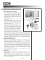
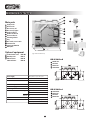
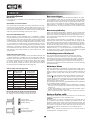
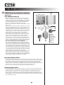
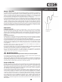
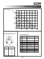
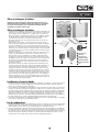
MOUNTING OF CONTROL PANELS AND SENSORS Control panel mounting, detaching and wiring The control panel is wired (2 m cable lenght) directly from the KWL EC 300 Pro connection box. The control panel can also be wired serially with a CO2 sensor or another control panel. Surface mounting of a control panel 1 + 2 3 A 4 Wiring 5 B M Cable: JY(ST)Y 2 x 2 x 0,6 mm2 + 0,5 mm2 A control panel is mounted on the wall or on a 1-part instument box. Attention: Faulty coupling ot the (+) wire damage the control panal! Width Height Depth 1 = orange 1 2 = white 1 3 = orange 2 4 = white 2 5 = metal 90 mm 110 mm 23 mm Control panel electronics board } =+ = =A =B = signal ground Several control panel addresses If two or more control panels are connected to the system, the addresses of the control panels have to be changed. (See Page 14, Section 1.3.12) For example 3 control panels. Connect the first control panel to the unit and change its address to 3. Connect the second control panel to the unit and change its address to 2. Connect the third control panel and check to see if its address is 1. Mounting and wiring of CO2 sensor The CO2 sensor can be connected to KWL EC 300 Pro directly from the connection box or in series with another CO2 sensor or control panel (see external electrical connections, on page 17). Surface mounting Electronic board with wiring 1 + 3 A 4 B 5 M NOTE! Faulty coupling ot the (+) wire damage the CO2 sensor! 38 76 The cables to sensors are laid directly from the connection box of KWL EC 300 Pro. Surface mounting 1 = orange 1 2 = white 1 3 = orange 2 4 = white 2 5 = metal } = + n. 21 VDC = =A =B = signal ground Wiring 14 Mounting and wiring of humidity sensor CO2 sensor electronic board % RF sensor electronics board 38 125 Humidity sensors Cable: JY(ST)Y 2 x 2 x 0,6 mm2 + 0,5 mm2 CO2 sensor bottom panel When mounting two or more humidity sensors, connect them to the terminal block of the connection box by connecting the first humidity sensor to %RF1, in place of the resistor 6K8 in the terminal block (remove the resistor in this case), and the second humidity sensor to %RF2. See the electrical diagram. 2 14 CO2 sensors CO2 sensors are connected individually. When the first CO2 sensors has been connected to the system, the unit is switched on. After this, the unit gives the sensor an address. Follow the same steps for other CO2 sensors. If control panels have the same address, they go to bus fault state. In this case, remove one of the control panels and change the address of the other panel. The above mentioned situation can arise in connection with the later installation of an additional control panel. 125 Panel adress 1 76 Cable: 2 x 0,5 mm2 8 S +