1
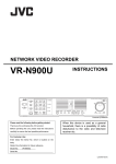
NETWORK VIDEO RECORDER
VR-N900U
STARTUP GUIDE
Powered by Milestone
Please read the following before getting started:
Precautions for use
Thank you for purchasing this JVC product.
• The hard disk drive (HDD) contained within this
Before operating this unit, please read the instructions
Digital video recorder is a fragile, precision
carefully to ensure the best possible performance.
apparatus. Handle it with extreme care and do not
subject it to physical shock.
• The HDD is most susceptible to damage when the
For Customer Use:
Enter below the Serial No. which is located on the
body.
Retain this information for future reference.
Model No.
Serial No.
VR-N900U
unit is on or when the HDD is being accessed.
• Before moving the network video recorder, wait one
minute after unplugging the power cord.
• Do not switch off the power on the rear panel or
unplug the power cord during recording or playback,
or when the hard disk drive is being accessed. It will
result in damage.
LST0495-001A
IMPORTANT SAFEGUARDS
1.
2.
3.
4.
5.
6.
7.
8.
9.
10.
11.
12.
13.
14.
15.
16.
17.
18.
19.
I
Read all of these instructions.
Save these instructions for later use.
All warnings on the product and in the operating instructions should be adhered to.
Unplug this appliance system from the wall outlet before cleaning. Do not use liquid cleaners or aerosol
cleaners. Use a damp cloth for cleaning.
Do not use attachments not recommended by the appliance manufacturer as they may cause hazards.
Do not use this appliance near water - for example, near a bathtub, washbowl, kitchen sink, or laundry tub, in a
wet basement, or near a swimming pool, etc.
Do not place this appliance on an unstable cart, stand, or table. The appliance may
fall, causing serious injury to a child or adult, and serious damage to the appliance.
Use only with a cart or stand recommended by the manufacturer, or sold with the appliance.
Wall or shelf mounting should follow the manufacturer’s instructions, and should use
a mounting kit approved by the manufacturer.
An appliance and cart combination should be moved with care. Quick stops, excessive
force, and uneven surfaces may cause the appliance and cart combination to overturn.
Slots and openings in the cabinet and the back or bottom are provided for ventilation, and
to insure reliable operation of the appliance and to protect it from overheating, these
openings must not be blocked or covered. The openings should never be blocked by placing the appliance on
a bed, sofa, rug, or other similar surface. This appliance should never be placed near or over a radiator or heat
register. This appliance should not be placed in a built-in installation such as a bookcase unless proper
ventilation is provided.
This appliance should be operated only from the type of power source indicated on the marking label. If you
are not sure of the type of power supplied to your home, consult your dealer or local power company. For
appliance designed to operate from battery power, refer to the operating instructions.
This appliance system is equipped with a 3-wire grounding type plug (a plug having a third (grounding pin).
This plug will only fit into a grounding-type power outlet. This is a safety feature. If you are unable to insert the
plug into the outlet, contact your electrician to replace your obsolete outlet. Do not defeat the safety purpose of
the grounding plug.
For added protection for this product during a lightning storm, or when it is left unattended and unused for long
periods of time, unplug it from the wall outlet and disconnect the antenna or cable system. This will prevent
damage to the product due to lightning and power-line surges.
Do not allow anything to rest on the power cord. Do not locate this appliance where the cord will be abused by
persons walking on it.
Follow all warnings and instructions marked on the appliance.
Do not overload wall outlets and extension cords as this can result in fire or electric shock.
Never push objects of any kind into this appliance through cabinet slots as they may touch dangerous voltage
points or short out parts that could result in a fire or electric shock. Never spill liquid of any kind on the
appliance.
Do not attempt to service this appliance yourself as opening or removing covers may expose you to dangerous
voltage or other hazards. Refer all servicing to qualified service personnel.
Unplug this appliance from the wall outlet and refer servicing to qualified service personnel under the following
conditions:
a. When the power cord or plug is damaged or frayed.
b. If liquid has been spilled into the appliance.
c. If the appliance has been exposed to rain or water.
d. If the appliance does not operate normally by following the operating instructions. Adjust only those controls
that are covered by the operating instructions as improper adjustment of other controls may result in
damage and will often require extensive work by a qualified technician to restore the appliance to normal
operation.
e. If the appliance has been dropped or the cabinet has been damaged.
f. When the appliance exhibits a distinct change in performance - this indicates a need for service.
When replacement parts are required, be sure the service technician has used replacement parts specified by
the manufacturer that have the same characteristics as the original part. Unauthorized substitutions may result
in fire, electric shock, or other hazards.
Upon completion of any service or repairs to this appliance, ask the service technician to perform routine safety
checks to determine that the appliance is in safe operating condition.
SAFETY PRECAUTIONS (for USA)
CAUTION
ATTENTION
RISK OF ELECTRIC
SHOCK DO NOT OPEN
RISQUE D’ELECTROCUTION NE PAS OUVRIR
CAUTION: TO REDUCE THE RISK OF ELECTRIC SHOCK,
DO NOT REMOVE COVER (OR BACK).
NO USER-SERVICEABLE PARTS INSIDE.
REFER SERVICING TO QUALIFIED SERVICE PERSONNEL
ATTENTION: POUR EVITER TOUT RISQUE D’ELECTROCUTION
NE PAS OUVRIR LE BOITER.
AUCUNE PIECE INTERIEURE N’EST
A REGLER PAR L’UTILISATEUR.
SE REFERER A UN AGENT QUALIFIE EN CAS DE PROBLEME.
The lightning flash with arrowhead symbol, within an
equilateral triangle, is intended to alert the user to
the presence of uninsulated “dangerous voltage”
within the product’s enclosure that may be of
sufficient magnitude to constitute a risk of electric
shock to persons.
Le symbole de l’éclair à l’intérieur d’un triangle
équilatéral est destiné à alerter l’utilisateur sur la
présence d’une “tension dangereuse” non isolée
dans le boîtier du produit. Cette tension est
suffisante pour provoquer l’électrocution de
personnes.
The exclamation point within an equilateral triangle is
intended to alert the user to the presence of
important operating and maintenance (servicing)
instructions in the literature accompanying the
appliance.
Le point d’exclamation à l’intérieur d’un triangle
équilatéral est destiné à alerter l’utilisateur sur la
présence d’opérations d’entretien importantes au
sujet desquelles des renseignements se trouvent
dans le manuel d’instructions.
WARNING:
TO REDUCE THE RISK OF FIRE OR ELECTRIC
SHOCK, DO NOT EXPOSE THIS APPLIANCE TO
RAIN OR MOISTURE.
This unit should be used with 120 V to 240 V AC only.
CAUTION:
To prevent electric shocks and fire hazards, DO NOT
use any other power source.
NOTE:
The rating plate (serial number plate) is on the rear of the unit.
INFORMATION:
This equipment has been tested and found to comply with the limits
for a Class A digital device, pursuant to Part 15 of the FCC Rules.
These limits are designed to provide reasonable protection against
harmful interference when the equipment is operated in a
commercial environment.
This equipment generates, uses, and can radiate radio frequency
energy and, if not installed and used in accordance with the
instruction manual, may cause harmful interference to radio
communications.
Operation of this equipment in a residential area is likely to cause
harmful interference in which case the user will be required to correct
the interference at his own expense.
* Ces symboles ne sont utilisés qu’aux Etats-Unis.
AVERTISSEMENT:
POUR EVITER LES RISQUES D’INCENDIE OU
D’ELECTROCUTION,
NE
PAS
EXPOSER
L’APPAREIL A L’HUMIDITE OU A LA PLUIE.
Ce magnétoscope ne doit être utilisé que sur du courant
alternatif en 120 V à 240 V.
ATTENTION:
Afin d’éviter tout resque d’incendie ou d’électrocution, ne pas
utiliser d’autres sources d’alimentation électrique.
REMARQUE:
La plaque d’identification (numéro de série) se trouve sur le panneau
arrière de l’appareil.
CAUTION:
RED color indications on the operation panel are provided but they
are not safety related, RED color indications :
(1) For Recording Indicator
(2) For Alarm Indicator
(3) For Warning Indicator
CAUTION:
CHANGES OR MODIFICATIONS NOT APPROVED BY JVC
COULD VOID USER’S AUTHORITY TO OPERATE THE
EQUIPMENT.
NOTE:
The rating plate (serial number plate) is on this unit.
WARNING:
TO REDUCE THE RISK OF FIRE OR ELECTRIC SHOCK, DO NOT
EXPOSE THIS APPLIANCE TO RAIN OR MOISTURE.
THIS DEVICE COMPLIES WITH PART 15 OF THE FCC RULES.
OPERATION IS SUBJECT TO THE FOLLOWING TWO
CONDITIONS: (1) THIS DEVICE MAY NOT CAUSE HARMFUL
INTERFERENCE, AND (2) THIS DEVICE MUST ACCEPT ANY
INTERFERENCE RECEIVED, INCLUDING INTERFERENCE THAT
MAY CAUSE UNDESIRED OPERATION.
II
SAFETY PRECAUTIONS
IMPORTANT (In the United Kingdom)
Mains Supply (AC 230 V)
WARNING - THIS APPARATUS
MUST BE EARTHED
The wires in this mains lead are coloured in accordance
with the following code;
GREEN-and-YELLOW : EARTH
BLUE : NEUTRAL
BROWN : LIVE
As the colours of the wires in the mains lead of this
apparatus may not correspond with the coloured
markings identifying the terminals in your plug, proceed
as follows.
The wire which is coloured GREEN-AND-YELLOW must
be connected to the terminal in the plug which is marked
with the letter E or by the safety earth symbol or coloured
GREEN or GREEN-AND-YELLOW.
The wire which is coloured BLUE must be connected to
the terminal which is marked with the letter N or which is
coloured BLACK. The wire which is coloured BROWN
must be connected to the terminal which is marked with
the letter L or coloured RED.
POWER SYSTEM
Connection to the mains supply
This unit operates on voltage of 120 V to 240 V AC,
50 Hz/60 Hz.
WARNING:
TO REDUCE THE RISK OF FIRE OR ELECTRIC
SHOCK, DO NOT EXPOSE THIS APPLIANCE TO RAIN
OR MOISTURE.
CAUTION
To prevent electric shock, do not open the cabinet. No
user serviceable parts inside. Refer servicing to qualified
service personnel.
Note:
The rating plate and the safety caution are on the rear
and top of the unit.
Caution for AC Power Cord
FOR YOUR SAFETY PLEASE READ THE FOLLOWING TEXT CAREFULLY.
Appropriate AC Power Cord must be used in each local area.
FOR CONTINENTAL EUROPE, ETC.
Not to be used in the U.K.
III
FOR U.K. ONLY
If the plug supplied is not suitable for your socket outlet,
it should be cut off and appropriate one fitted.
WARNING
WARNING
It should be noted that it may be unlawful to re-record
pre-recorded tapes, records, or discs without the consent
of the owner of copyright in the sound or video recording,
broadcast, or cable programme and in any literary,
dramatic, musical or artistic work embodied therein.
This is a Class A product. In a domestic environment this
product may cause radio interference in which case the
user may be required to take adequate measures.
CAUTION
RED colour indications on the operation panel are
provided but they are not safety related, RED colour
indications :
(1) For Recording Indicator
(2) For Alarm Indicator
(3) For Warning Indicator
WARNING
For PLUGGABLE EQUIPMENT, the socket outlet shall
be installed near the equipment and shall be easily
accessible.
Information for Users on Disposal of Old Equipment
[European Union]
Attention:
This symbol is
only valid in the
European
Union.
This symbol indicates that the electrical and electronic equipment should not be disposed as general
household waste at its end-of-life. Instead, the product should be handed over to the applicable collection
point for the recycling of electrical and electronic equipment for proper treatment, recovery and recycling in
accordance with your national legislation.
By disposing of this product correctly, you will help to conserve natural resources and will help prevent
potential negative effects on the environment and human health which could otherwise be caused by
inappropriate waste handling of this product. For more information about collection point and recycling of this
product, please contact your local municipal office, your household waste disposal service or the shop where
you purchased the product.
Penalties may be applicable for incorrect disposal of this waste, in accordance with national legislation.
(Business users)
If you wish to dispose of this product, please visit our web page www.jvc-europe.com to obtain information
about the take-back of the product.
[Other Countries outside the European Union]
If you wish to dispose of this product, please do so in accordance with applicable national legislation or other
rules in your country for the treatment of old electrical and electronic equipment.
Dear Customer,
This apparatus is in conformance with the valid European
directives and standards regarding electromagnetic
compatibility and electrical safety.
CAUTION
(1) Please do not detach the front cover.
(2) Please put it when the front cover comes off.
European representatives of Victor Company of Japan
Limited is:
JVC Technology Centre Europe GmbH
P.O. Box 10 05 52
61145 Friedberg
Germany
IV
SICHERHEITSVORKEHRUNGEN (for Germany)
SPANNUNGSVERSORGUNG
WARNUNG
Anschluss am Netz
Die Betriebsspannung für dieses Gerät beträgt
AC120 V bis 240 V, 50 Hz/60 Hz
Bei dem Gerät handelt es sich um ein Klasse-A-Produkt.
In Haushaltsumgebungen kann ein solches Produkt
Funkstörungen verursachen. In einem solchen Fall muss
der Benutzer geeignete Maßnahmen ergreifen.
ACHTUNG:
UM DER GEFAHR VON BRÄNDEN UND
ELEKTRISCHEN SCHLÄGEN VORZUBEUGEN, DARF
DIESES GERÄT WEDER DEM REGEN NOCH HOHER
FEUCHTIGKEIT AUSGESETZT WERDEN.
ACHTUNG
Um elektrische Schläge zu vermeiden, das Gehäuse nie
öffnen. Im Innern befinden sich keine Teile, die vom
Benutzer gewartet werden können. Überlassen Sie die
Wartung qualifiziertem Service-Personal.
Sehr geehrter Kunde, sehr geehrte Kundin,
dieses Gerät stimmt mit den gültigen europäischen
Richtlinien und Normen bezüglich
elektromagnetischer Verträglichkeit und elektrischer
Sicherheit überein.
Die europäische Vertretung für die Victor Company of
Japan, Limited ist:
JVC Technology Centre Europe GmbH
Postfach 10 05 52
61145 Friedberg
Deutschland
Benutzerinformationen zur Entsorgung alter Geräte
[Europäische Union]
Hinweis:
Dieses Symbol
ist nur in der
Europäischen
Union gültig.
Dieses Symbol zeigt an, dass das elektrische bzw. elektronische Gerät nicht als normaler Haushaltsabfall
entsorgt werden soll. Stattdessen sollte das Produkt zur fachgerechten Entsorgung, Weiterverwendung und
Wiederverwertung in Übereinstimmung mit der Landesgesetzgebung einer entsprechenden Sammelstelle für
das Recycling elektrischer und elektronischer Geräte zugeführt werden.
Die korrekte Entsorgung dieses Produkts dient dem Umweltschutz und verhindert mögliche Schäden für die
Umwelt und die menschliche Gesundheit, welche durch unsachgemäße Behandlung des Produkts auftreten
können. Weitere Informationen zu Sammelstellen und dem Recycling dieses Produkts erhalten Sie bei Ihrer
Gemeindeverwaltung, Ihrem örtlichen Entsorgungsunternehmen oder in dem Geschäft, in dem Sie das
Produkt gekauft haben.
Für die nicht fachgerechte Entsorgung dieses Abfalls können gemäß der Landesgesetzgebung Strafen
ausgesprochen werden.
(Geschäftskunden)
Wenn Sie dieses Produkt entsorgen möchten, besuchen Sie bitte unsere Webseite www.jvc-europe.com, um
Informationen zur Rücknahme des Produkts zu erhalten.
[Andere Länder außerhalb der Europäischen Union]
Wenn Sie dieses Produkt entsorgen möchten, halten Sie sich dabei bitte an die entsprechenden
Landesgesetze und andere Regelungen in Ihrem Land zur Behandlung elektrischer und elektronischer Geräte.
Erklärung zum Rauschen (für die Bundesrepublik Deutschland):
Maschinenlärminformations-Verordunung 3. GPSGV, 06.01.2004: Der höchste
Schalldruckpegel beträgt 70 dB(A) oder weniger gemäß EN ISO 7779
Hinweis zum Netzanschlußkabel
Zu Ihrer Sicherheit lesen Sie bitte das folgende sorgfältig.
Verwenden Sie ausschließlich ein in Ihrem Land zulässiges Netzkabel.
Für Kontinentaleuropa
Nicht für den Gebrauch in Großbritannien.
V
Nur für Großbritannien
WICHTIGE SICHERHEITSHINWEISE
1.
2.
3.
4.
5.
6.
7.
8.
9.
10.
11.
12.
13.
Alle Warnungen auf dem Produkt sowie in der Betriebsanleitung sind unbedingt zu beachten.
Ziehen Sie den Netzstecker dieses Systems aus der Steckdose, bevor Sie das Gerät reinigen. Benutzen Sie
keine Flüssigreiniger und keine Sprühreiniger. Verwenden Sie zum Reinigen lediglich ein leicht angefeuchtetes
Tuch.
Benutzen Sie keine Zubehörteile, die nicht vom Hersteller empfohlenen werden; diese können Gefahren und
Risiken verursachen.
Benutzen Sie das Gerät nicht in der Nähe von Wasser und sonstigen Flüssigkeiten - beispielsweise nicht in
der Nähe von Badewannen, Handwaschbecken, Spülen, Waschbecken, nicht in feuchten Kellern, nicht in der
Nähe von Schwimmbecken, und so weiter.
Stellen Sie das Gerät nicht auf instabile Wagen, Ständer oder Tische. Das Gerät kann herunterfallen,
ernsthafte Verletzungen bei Kindern und Erwachsenen hervorrufen und auch selbst schwer beschädigt
werden. Benutzen Sie ausschließlich Wagen oder Ständer, die vom Hersteller empfohlen oder mit dem Gerät
verkauft wurden. Bei der Aufstellung im Regal halten Sie sich an die Anweisungen des Herstellers. Zusätzlich
sollten Sie einen vom Hersteller zugelassenen Montagesatz verwenden. Eine Kombination aus Gerät und
Wagen sollte grundsätzlich mit großer Sorgfalt bewegt werden. Schnelle Stopps, übermäßiger Krafteinsatz und
unebener Untergrund können zum Umkippen der Gerät-Wagen-Kombination führen.
Schlitze und Öffnungen im Gehäuse sowie an Rückwand und Unterseite dienen der Belüftung des Gerätes
und sorgen dafür, dass das Gerät zuverlässig arbeiten und sich nicht überhitzen kann. Daher dürfen Sie diese
Öffnungen auf keinen Fall blockieren oder abdecken. Die Öffnungen können beispielsweise blockiert werden,
wenn Sie das Gerät auf ein Bett, ein Sofa, einen Teppich oder einen ähnlichen Untergrund stellen. Dies darf
auf keinen Fall geschehen. Das Gerät sollte niemals in der Nähe oder über Heizgeräten oder anderen
Geräten, die Wärme abstrahlen, aufgestellt werden. Geschlossene Aufstellungsorte wie Bücherregale eignen
sich nur dann zur Aufstellung des Gerätes, wenn eine ordnungsgemäße Belüftung jederzeit gewährleistet ist.
Das Gerät ist mit einem Schutzkontaktstecker (einem Stecker mit Erdungsbügeln an beiden Seiten)
ausgestattet. Dieser Stecker lässt sich nur in eine geerdete Schutzkontaktsteckdose einstecken. Dies dient
Ihrer Sicherheit. Falls sich der Stecker nicht problemlos in die Steckdose einstecken lassen sollte, lassen Sie
die (veraltete) Steckdose von einem Elektriker austauschen. Versuchen Sie niemals, die Sicherheit, die Ihnen
ein Schutzkontaktstecker bietet, auf irgendeine Weise außer Kraft zu setzen.
Um das Gerät während eines Gewitters oder für einen längeren unbeaufsichtigten Zeitraum zu schützen,
ziehen Sie den Netzstecker aus der Steckdose, und trennen Sie die Antenne oder das Kabelsystem ab.
Dadurch vermeiden Sie Produktschäden, die als Folge eines Blitzeinschlags oder Stromstosses auftreten
können.
Sorgen Sie dafür, dass nichts auf dem Netzkabel zu liegen kommt. Platzieren Sie das Gerät nicht an Stellen,
an denen Personen auf das Kabel treten und es beschädigen können.
Beachten Sie alle Warnungen und Anleitungen, die auf dem Gerät vermerkt sind.
Überlasten Sie niemals Steckdosen oder Verlängerungskabel: Dies kann leicht zu Stromschlägen und Bränden
führen.
Stecken Sie niemals Gegenstände gleich welcher Art durch die Gehäuseöffnungen in das Gerät; dabei können
Hochspannung führende Teile berührt und Kurzschlüsse verursacht werden: Es besteht akute Brand- und
Stromschlaggefahr. Lassen Sie niemals Flüssigkeiten gleich welcher Art auf oder in das Gerät gelangen.
Unter folgenden Bedingungen ziehen Sie den Netzstecker und lassen das Gerät von einem qualifizierten
Techniker überprüfen und reparieren:
a. Wenn das Netzkabel oder der Netzstecker beschädigt ist; auch kleinste Beschädigungen können große
Auswirkungen haben.
b. Falls Flüssigkeit auf oder in das Gerät gelangt sein sollte.
c. Wenn das Gerät mit Regen oder Wasser in Berührung gekommen ist.
d. Wenn das Gerät nicht normal funktioniert, obwohl die Betriebsanleitung befolgt wurde. Passen Sie nur die
Steuerungen an, die in der Betriebsanleitung vermerkt sind. Die Anpassung anderer Steuerungen kann
ansonsten zu Schäden führen, die dann sehr aufwändig von einem qualifizierten Techniker repariert werden
müssen, damit das Gerät wieder einwandfrei funktioniert.
e. Falls das Gerät fallen gelassen oder das Gehäuse beschädigt wurde.
f. Falls sich die Leistung des Gerätes spürbar ändern sollte - in diesem Fall muss das Gerät dringend überprüft
und/oder repariert werden.
VI
SICHERHEITSVORKEHRUNGEN (for Germany)
ACHTUNG
(1) Nehmen Sie nicht die Frontabdeckung ab.
(2) Falls sich die Frontabdeckung lösen sollte, setzen Sie sie sofort wieder auf.
Lager- und Verwendungsort:
■ Vermeiden Sie, den Rekorder an folgenden Plätzen zu lagern oder zu verwenden.
Eine Missachtung kann zu einem Fehler oder einer Störung führen.
• Extrem heiße oder kalte Plätze, die außerhalb der zulässigen Betriebstemperatur liegen (5ºC – 40ºC)
• Feuchte oder trockene Plätze, die außerhalb der zulässigen Feuchtigkeit für den Betrieb liegen (30% – 80%)
• Plätze, an denen starke Magnetfelder erzeugt werden, beispielsweise Tranformatoren oder Motoren
• Plätze in der Nähe von Geräten, die elektrische Wellen erzeugen, beispielsweise Sender-Empfänger oder Handys
• Staubige oder sandige Plätze
• Plätze, die starken Erschütterungen ausgesetzt sind
• Plätze, die zu Kondensationsbildung neigen, beispielsweise ein Fenster
• Plätze, die Strahlung, Röntgenstrahlen oder ätzende Gase erzeugen
Handhabung des Recorders:
■ Stapeln Sie Recorder nicht aufeinander. Dies kann zu erhöhter Geräuschentwicklung und aufgrund von
Überhitzung zu Fehlfunktionen oder zum Totalausfall der Geräte bis hin zu Bränden führen.
■ Blockieren Sie nicht die Belüftungsschlitze. Sind die Öffnungen blockiert, bildet sich im Inneren des Recorders
Hitze, wodurch ein Brand entstehen kann. Benutzen Sie den Recorder nicht in vertikaler Position, nicht auf dem
Kopf stehend, nicht mit der Front nach oben.
■ Legen Sie keine Gegenstände auf dem Recorder ab. Wenn Sie einen schweren Gegenstand, beispielsweise
einen Fernsehbildschirm oder einen großen Gegenstand, der über die Kante des Recorders hinausragt, auf den
Recorder stellen, kann dieser aus dem Gleichgewicht geraten. Dadurch besteht die Gefahr, dass der Recorder
kippt oder auf den Boden fällt und Verletzungen verursacht.
■ Steigen Sie nicht auf den Recorder. Der Recorder könnte umfallen oder beschädigt werden. Achten Sie
besonders auf kleine Kinder.
■ Stellen Sie keine wasserhaltigen Gegenstände auf dem Recorder ab (beispielsweise Vase, Blumentopf, Gläser,
Kosmetika oder Chemikalien). Tritt Wasser in das Innere des Recorders ein, kann dies einen Brand oder einen
Kurzschluss verursachen.
■ Stecken Sie keine Fremdkörper in den Recorder. Dringen metallische oder brennbare Gegenstände durch die
Belüftungsschlitze o.ä. in den Recorder ein, kann dies einen Brand oder einen Kurzschluss verursachen.
Pflege des Recorders
■ Wischen Sie den Recorder mit einem weichen Tuch ab.
Verwenden Sie keine Verdünner oder Benzol. Dies könnte dazu führen, dass die Oberfläche zersetzt oder matt wird. Im Fall von
hartnäckigen Flecken, wischen Sie diese zunächst mit einem neutralen und mit Wasser verdünnten Reiniger ab, und wischen Sie die
Fläche dann trocken.
Transport des Recorders
■ Trennen Sie vor dem Transport des Recorders alle Kabel ab. Schalten Sie den Recorder vor dem Transport aus
und stellen Sie sicher, dass der Netzstecker aus der Steckdose entfernt wurde. Wird dies nicht beachtet, kann dies
zu Beschädigungen am Kabel, einem Brand oder einem Stromschlag führen.
■ Transportieren oder starten Sie die Installation des Recorders nicht, solange er noch eingeschaltet ist oder
unmittelbar nachdem er ausgeschalten wurde (ungefähr eine Minute).
■ Achten Sie bei der Verpackung darauf, dass der Recorder vor Stößen geschützt ist.
■ Gehen Sie vorsichtig mit dem Recorder um. Setzen Sie ihn keinesfalls Erschütterungen oder Stößen aus.
VII
Netzkabel
■ Verwenden Sie das mit dem Recorder gelieferte Netzkabel ausschließlich für dieses Gerät.
■ Stellen Sie keine schweren Gegenstände auf das Netzkabel und vermeiden Sie, dass das Netzkabel unter dem
Recorder eingeklemmt wird. Wird dies nicht beachtet, kann dies zu Beschädigungen am Kabel, einem Brand oder
einem Stromschlag führen.
■ Benutzen Sie grundsätzlich das mit dem Recorder gelieferte Netzkabel. Die Verwendung eines anderen oder
beschädigten Kabels kann zu Stromschlägen und Bränden führen.
■ Stecken Sie das Netzkabel nicht während der Aufnahme, Wiedergabe oder während eines Zugriffs auf das
Laufwerk aus.
Hinterer Gehäusedeckel: Achtung:
Sämtliche Audio-, Video- und LAN-Verbinder dürfen nicht direkt an ein Kabelverteilungssystem (Außenbereiche oder zwischen
Gebäuden) angeschlossen werden.
Hintere E/A-Terminals: Hinweis: Verwenden Sie dieses Terminal nicht für eine Sicherungserdung.
Einbau des VR-N900U in einem EIA-Rack mit Montageklammern:
1 Montieren Sie die seitliche Klammer mit M4-Schrauben an der rechten und linken Seite. Diese Schrauben sind im
Lieferumfang des VR-N900U enthalten.
2 Entfernen Sie 4 Schrauben und 4 Füße vom Boden des VR-N900U.
3 Befestigen Sie diese mit M5-Schrauben am Rack. Diese Schrauben sind im Lieferumfang des VR-N900U enthalten.
Achtung
• Stellen Sie keinerlei Gegenstände auf den VR-N900U, wenn dieser in einem Rack montiert ist. Dies kann durch
Ungleichgewicht zum Herunterfallen des Recorders führen und Verletzungen oder Schäden verursachen.
• Werden zwei oder mehrere Recorder in dem Rack eingebaut, achten Sie darauf, dass der Abstand mindestens die Größe
eines Recorders beträgt.
• Bauen Sie den VR-N900U nicht in ein Rack ein, wenn die Umgebungstemperatur 40°C oder mehr beträgt.
• Achten Sie beim Einbau in einem Rack darauf, dass die Innentemperatur der Rack-Einheit 40°C oder weniger beträgt.
• Wenn Sie das Gerät in einem Rack montieren, halten Sie einen Abstand von mindestens 15 cm zwischen Rack und der
Rückwand des Gerätes ein.
Beachten Sie im Fall eines Einbaus oder Wartung dieses Geräts in einem Rack die speziellen Vorsichtsmaßnahmen, um
sicherzustellen, dass das System nicht an Stabilität verliert.
Folgende Richtlinien dienen zur Sicherstellung Ihrer Sicherheit.
Ist dieses Gerät die einzige Einheit, die in dem Rack einzubauen ist, so sollte es auf dem Rack-Boden angebracht werden. Wird
das Rack teilweise genutzt, bauen Sie die Teile von unten nach oben ein. Die schwerste Komponente sollte stets unten im Rack
eingebaut werden. Ist das Rack mit stabilisierendem Zubehör ausgestattet, montieren Sie zunächst diese Stabilisatoren, bevor
Sie das Gerät in das Rack einbauen oder warten.
Achtung:
Vor dem Einbau in das Rack ist sicherzustellen, dass das Rack sicher und vor dem Umfallen geschützt ist.
Technische Daten:
Allgemein:
Zulässiger Temperaturbereich bei der Lagerung: .......................... -20 °C bis 60 °C
Stromaufnahme: .................................................................................. 1,7 A (max.)
Gewicht: ................................................................................................etwa 7,7 kg
VIII
Getting Started
Main Features
•
Automatic detection of IP cameras
Considerably reduces the complicated task of adding
cameras to the system.
•
Built-in hard disk drive with a high capacity of 250 GB
•
Built-in analog input in 4 channels
•
Simultaneous recording of 120 images/sec in 9 channels
•
Simultaneous playback mode
Playback, jog/shuttle playback and skip play of recorded
images are possible during recording.
•
Contents
Getting Started
Main Features.......................................................................2
Contents ...............................................................................2
PRECAUTIONS....................................................................3
Copyrights.............................................................................4
Part Names and Functions ...................................................5
Direct search
Searches quickly for the desired date/time and alarm position.
•
•
Recovery recording during power failure
Preparation
Upon recovery from a power failure during recording, the VRN900U will resume recording in the mode prior to the failure.
Installing the VR-N900U to EIA Rack ................................. 11
Alarm recording
Switches automatically to the alarm recording mode when
alarm signals are received during recording.
•
•
System Connection Example.............................................. 11
Initial Setup .........................................................................12
Motion detection
Automatically detects motion in the specified live image
and starts recording.
Basic Operation
The detection area can be specified for each camera.
Viewing Live Images...........................................................15
Transmission of alarm e-mails
Viewing Recorded Images..................................................17
E-mails can be sent when an alarm is input or motion is
detected.
Others
How to Read this Manual
■ How to Read the Symbols
Caution
Indicates points to note when operating the
recorder.
Note
Indicates useful information, such as features
and restrictions on use.
☞
Troubleshooting ..................................................................18
Specifications......................................................................19
Indicates a reference page or reference item.
■ Contents of this Manual
• The contents of this manual are the copyright of JVC.
They may not be reproduced in part or in whole without
the permission of JVC.
• All product names stated in this manual are trademarks
or registered trademarks of their respective companies.
Marks such as ™, ® and © are omitted in this manual.
• Milestone and XProtect Enterprise are registered
trademarks of Milestone Systems.
• Designs, specifications and other contents of this
manual are subject to change without prior notice.
2
•
This STARTUP GUIDE deals only with the initial
setup and basic operational procedures on the VRN900U.
Besides the STARTUP GUIDE, the VR-N900U
INSTRUCTIONS is also provided on a CD-ROM that
explains further details on the operation procedures.
For details, please refer to the CD-ROM.
PRECAUTIONS
Maintaining the recorder
■ Wipe the recorder with a soft cloth.
Place of storage and use
■ Avoid storing or using the recorder in the following
places.
Failure to do so may lead to malfunction or breakdown.
• Extremely hot or cold places beyond the allowable
temperature for operation (5ºC – 40ºC)
• Humid or dry places beyond the allowable humidity
range for operation (30% – 80%)
• Places that generate strong magnetic fields, e.g.
transformers or motors
• Places near devices that generate electric waves, e.g.
transceivers or mobile phones
• Dusty or sandy places
• Places exposed to strong vibration
• Places prone to condensation, such as by a window
• Places that generate radiation, X-rays or corrosive
gases
Handling the recorder
■ Do not stack recorders on top of each other.
Doing so may cause malfunction or failure due to
overheating or noise, or lead to fire.
■ Do not block the ventilation openings.
If the openings are blocked, heat will build up inside the
recorder, leading to fire. Do not use the recorder in a vertical
position or when it is placed upside down or face up.
■ Do not place any objects on the recorder.
Placing a heavy object such as a TV monitor or a large
object that protrudes over the edge of the recorder on top
of the recorder may cause it to overbalance and topple
over or fall off and cause injury.
■ Do not climb on the recorder.
Doing so may cause the recorder to topple over or be
damaged. Particular attention should be paid to small
children.
■ Do not place anything containing water on the
recorder (such as a vase, plant pot, glass,
cosmetics or chemicals).
If water gets inside the recorder, it may lead to fire or
electric shock.
■ Do not insert foreign objects into the recorder.
If any metal object or flammable item gets into the
recorder through the ventilation openings, etc., it may
lead to fire or electric shock.
Do not use thinner or benzene as this may cause the
surface to dissolve or tarnish. For stubborn stains, wipe
first with a water-diluted neutral detergent and then wipe
dry.
Moving the recorder
■ Disconnect the cables before moving the recorder.
Before moving the recorder, turn off the power and be
sure to unplug the power cable from the electric outlet.
Failure to do so may result in damage to the cable or lead
to fire or electric shock.
■ Do not move the recorder or commence the
installation process when the power is turned on or
immediately after the power has been turned off
(for approximately one minute).
The hard disk will continue to rotate due to inertia for a
few moments after the power has been turned off and
any vibration or physical shock during this time may
result in damage.
■ Wrap the recorder in protective packing to prevent
physical shocks.
■ Handle the recorder with care. Do not subject it to
vibration or physical shocks.
Saving power
■ For safety reasons and to save energy, unplug the
power cable when the recorder is not in use for
long periods.
Power cable
■ Do not use the power cable supplied with the
recorder on other devices.
■ Do not place heavy items on the power cable or
trap the cable under the recorder.
Doing so may result in damage to the cable or lead to fire
or electric shock.
■ Be sure to use the power cable supplied with the
recorder.
Using a different type or damaged cable may lead to fire
or electric shock.
■ Do not unplug the power cable during recording or
playback, or when the hard disk drive is being
accessed.
3
Getting Started
Hard Disk Drive
Consumable Parts
The distance between the head and disk that read and write
data on the hard disk drive (hereinafter known as the HDD) is
a miniscule 0.02µm. Vibrations and physical shocks to the
HDD may therefore result in the head coming into contact
with the disk, producing dents and scratches to its surface.
This will consequently prevent data from being read, and will
result in disk crashes if use is continued. It is therefore
necessary to handle the recorder with great care.
The table below is a list of the consumable parts. The parts
fee that accompanies these replacement and repair costs
includes technical and official trip fees that are charged even
during the guarantee period.
■ Installation and Changing the Location of Installation
• Do not move the recorder or commence the installation
process when the power is turned on or immediately
after the power has been switched off (for approximately
one minute) under any circumstances. (The HDD will
continue to rotate due to inertia for a few moments after
the power has been switched off, and vibrations or
physical shocks will result in damage.)
• Wrap the recorder in protecting packing to prevent
physical shocks.
■ Handling
• Handle this equipment with care. Do not subject it to
physical shock.
• Do not unplug the power cord during recording or
playback, or when the HDD is being accessed.
■ It is recommended that an UPS (Uninterruptible
Power Supply) is used when installing additional
external hard disk drives to make sure the system
remains stable.
■ If a power failure occurs during formatting of hard
disk or disconnection, operation of the equipment
may be disabled even if it is connected to the UPS.
■ Please note that we will not provide compensation
for any failure during recording or playback due to
defects in this equipment or the hard disk drive.
■ Please note that recorded images will be erased
when replacing hard disks. Note that there are cases
where recorded images may be erased when
software is upgraded.
4
Part name
Remarks
Hard Disk Drive The exchange period will expire after
(HDD)
10,000 hours of use (approx. one year)
from the beginning date of use.
Fan Unit
The exchange period will expire after
30,000 hours of use (approx. three years)
from the beginning date of use.
In order to support exchange and maintenance of
consumable supplies, use the attached Installation date
label. Enter the beginning date of use on the Installation
date label and attach it to this equipment.
Copyrights
■ Unless the user is the holder of the copyrights to the
video and audio materials or has obtained the permission
of the copyright holder, the permission of the copyright
holder must be obtained to reproduce, modify or transmit
copyrighted work as video or audio material.
Reproducing, modifying or transmitting copyrighted work
without the permission of the copyright holder is regarded
as an infringement of the copyright law and may result in
liability for damages. The user is therefore recommended
to duly check the copyright license conditions before
using copyrighted work as video or audio material.
Furthermore, if the photographic rights of the subject
exist, permission must be obtained to take and use
(process) such photographs. The user is therefore
recommended to duly check the license conditions in this
regard.
Part Names and Functions
Front Panel
1
2
3 4 5
1
6
7
[OPERATE] button and indicator
Switches operation on or off. Press the button to turn
operation on and hold down the button to turn
operation off. The indicator blinks while the recorder is
starting up or shutting down. To forcibly reboot the
system, press and hold down the [OPERATE] button
while holding down the [FUNCTION] button.
2
[REC CONTROL] button and indicator
Switches the recording control mode on or off. The indicator
lights up when the recording control mode is set to on.
* The Main Menu cannot be displayed in recording
control mode or during recording.
* With the recording control mode, recording is carried
out in accordance with the settings in the [Camera
Record Setting] menu. For details, please refer to the
VR-N900U INSTRUCTIONS.
3
[SELECT] button and indicator
Switches the camera selection mode on or off. The indicator
lights up when the camera selection mode is set to on.
☞ Page 15
4
[PTZ/PRESET] button and indicator
Switches between the PTZ mode and PRESET mode.
The mode changes each time the button is pressed.
The indicator lights up when PTZ mode is selected
and blinks when PRESET mode is selected.
☞ Page 16
5
[SERIAL] port (TYPE-A)
Used to connect the communication control terminals
on a mouse (sold separately), flash memories (sold
separately) and UPS (sold separately).
CAUTION
• Use the [SERIAL] port on the rear panel for additional
hard disk drive connection. ( ☞ Page 8)
6
[ZOOM OUT/CANCEL] button
Selects ZOOM OUT when PTZ mode is selected
( ☞ Page 16) and selects a view in PRESET mode.
Cancels the selected values in the Main Menu
window. Press the [ZOOM OUT/CANCEL] button
while holding down the [FUNCTION] button to change
the resolution of VGA output.
7
[ZOOM IN/ENTER] button
Selects ZOOM IN when pressed in PTZ mode
( ☞ Page 16) and selects a view in PRESET mode.
Sets the selected values in the Main Menu window.
Press the [ZOOM IN/ENTER] button while holding
down the [FUNCTION] button to change the resolution
of VGA output.
5
Getting Started
22
21
20
19
18
17
8
8
9
10
11
12
13
14
Status indicators
■ WARNING indicator
Lights up when an error occurs. ( ☞ Page 18)
Goes off when the [ALARM CLEAR] button is held
down.
■ ALARM indicator
Lights up when an alarm is activated.
Goes off when the [ALARM CLEAR] button is
pressed.
■ HDD indicator
Lights up when the built-in hard disk drive is
accessed.
■ LOCK indicator
Lights up when operation is locked.
9
[FUNCTION] button
15
16
13 [REC/STOP] button
Press to start recording in all cameras. Press and hold
down to stop recording. In the recording control mode,
press and hold down to cancel the recording control
mode.
* Recording will not be started in cameras to which no
video signal is being input.
* With the forced recording mode, recording is carried
out in all cameras regardless of the settings in the
[Camera Record Setting] menu. Recording is carried
out in accordance with the frame rate selected in the
[Image storage settings]. For details, please refer to
the VR-N900U INSTRUCTIONS.
14 [STOP(PB)] button
Stops playback when pressed in playback mode.
Press the following buttons while holding down the
[FUNCTION] button to use the following features.
15 [PLAY] button
➀ [OPERATE] (press and hold down): Forcibly
reboots the system.
Plays back at the speed and in the direction specified
by the Shuttle Dial position.
➁ [REC CONTROL]: Displays the Main Menu.
➂ [LIVE/BROWSE] (press and hold down): Logs off
the system.
10 [SEARCH] button
Displays the date and time search screen in playback mode.
☞ Page 17
11 [KEY] button
Press to display or close the software keyboard.
* The software keyboard is used to enter figures and
characters. For details, please refer to the VR-N900U
INSTRUCTIONS.
12 [ALARM CLEAR] button
Cancels the alarm when an event occurs or motion is
detected.
6
16 [SKIP] button
■6
Press to move the option highlight in the reverse
direction in the menu windows or setup windows.
Jumps to the beginning of the previous sequence on
the selected camera when pressed in playback mode.
Press and hold down to jump to the first image in the
database of the selected camera.
■7
Press to move the option highlight in the forward
direction in the menu windows or setup windows.
Jumps to the beginning of the next sequence on the
selected camera when pressed in playback mode.
Press and hold down to jump to the last image in the
database of the selected camera.
• “Sequence” indicates a certain block of recorded images
triggered by an event or motion.
• Recorded images are stored in the database. “Database”
means the recorded data in this unit.
17 Jog dial
22 [LIVE/BROWSE] button and indicator
Plays back a single frame when rotated in playback
mode.
Switches between the [Live Viewing] mode and
[Recorded Image Display] mode. The indicator lights
up when [Live Viewing] mode is set. Press the [LIVE/
BROWSE] button in the wallpaper screen to display
the [Live Viewing] window. Press and hold down the
[LIVE/BROWSE] button while holding down the
[FUNCTION] button to log off the system. If [Auto
Logon] is set to [On], the system will automatically log
on immediately after you have logged off.
18 Shuttle dial
The position of the dial specifies the playback speed
and playback direction in playback mode. Playback
speed is selectable from x 1/20, x 1/5, x 1, x 2, x 5,
x 10 and x 20 according to the shuttle dial position.
19 [REC] indicator
Lights up during recording. Flashes during
EMERGENCY or EXT REC IN recording.
20 Center panel
CAUTION
• Do not remove the center panel.
21 Keypad and camera input indicator
■ [0] – [9]
Selects the camera input when viewing live images
and when playing back recorded images. The
indicator that corresponds to the selected camera
input lights up during camera selection mode. Used to
move the camera to the specified position during PTZ
mode, to enter the preset number during PRESET
mode and to narrow down the search date, month,
week and time in the search mode. When the Main
Menu is displayed, press [
] or [
] button to
move the option highlight. These buttons are also
used as numeric keys.
7
Getting Started
Rear Panel
12
13
11
10 9
8
1
2
3
1
4
5
6
7
7
[POWER] switch
Switches the power on or off.
Connector cover
CAUTION
Note
• Do not remove the connector cover.
• Be sure to press and hold down the [OPERATE] button on
the front panel to shut down the system before switching
off the power supply.
8
[LAN 2] connection interface (Intranet network)
For connection to the remote PC network using a LAN cable.
2
[AC IN (120-240V)
] power input terminal
Connect to an AC120-240V outlet using the power cable supplied.
3
[RESET]
Resets the system. Press this button when a malfunction occurs.
CAUTION
• Do not press this button in normal circumstances.
4
[AUDIO OUT] terminal (RCA)
Outputs live sound in live viewing mode.
Outputs recorded sound in playback mode.
Note
• Sound will not output in the following cases:
- When playing back still images, when running searches
other than X1, and when playing back frame-by-frame.
- When a menu or search menu is displayed during
playback.
5
[VGA OUT] terminal
[SERIAL] terminal
Used to connect the communication control terminals on a
mouse (sold separately), flash memories (sold separately), UPS
(sold separately) and additional disk drives (sold separately).
8
[CAMERA CONTROL] terminal
Lets you control the analog cameras.
10 [LAN 1] connection interface (Camera network)
For connection to the IP camera (sold separately) network
using a LAN cable.
11 Signal input/output terminals
For operating the VR-N900U using external alarm signals or
signals received from external devices, or for operating
external devices by outputting signals.
*Diameter of applicable cables: AWG22 to AWG28
12 [VIDEO IN] camera image signal input
terminals 1 to 4
Connect to the video output terminal of the analog camera
(sold separately).
13 [AUDIO IN] terminals 1 & 2 (RCA)
Connect to the audio output terminal of the device from
which audio signals are to be recorded.
Outputs live images, playback images and the menu windows.
6
9
CAUTION
• All Audio, Video, and LAN-connectors are not to be
directly connected to Cable Distribution Systems (outdoor
units or between buildings.)
Rear I/O Terminals
1
2
4
3
6
5
8
7
10
11
9
12
Input ports
1
[ALARM IN 1 to 4] terminals
Alarm recording is activated when signals are input to
these terminals.
2
[EMERGENCY] terminal
Recording is activated in all cameras when a signal is
input to this terminal.
* Recording will not be started in cameras to which no
video signal is being input.
3
[ALARM RESET] terminal
Output from the alarm output terminal is stopped when a
signal is input during alarm terminal output.
4
[EXT REC IN] terminal
Recording in all cameras is started or stopped by an
external signal.
* Recording will not be started in cameras to which no
video signal is being input.
5
[OPE ON/OFF] terminal
Switches between OPERATE on or off when a signal is input.
7
[ALARM OUT] terminal
Outputs a signal when recording is started by an alarm.
8
[WARNING OUT] terminal
Outputs a signal when an operation abnormality or
other error occurs on the hard disk.
9
[REC TALLY] terminal
Outputs the recording status of the VR-N900U.
10 [OPTION OUT 1 & 2] terminals
Outputs a signal when an event is detected.
11 [COMMON] terminal
Same as ➏.
12 [SIGNAL GND] terminal
The common grounding terminal. Connected to the
signal grounding terminal on the connected device.
Note
• Do not use this terminal for protective earthing.
Output ports
6
[COMMON] terminal
The common grounding terminal. Connected to the
signal grounding terminal on the connected device.
(This can be used when there are insufficient common grounding terminals.)
9
Getting Started
Camera Control Terminals
Refer to the following table for connection cables. Carefully read the instruction manual supplied with the connected device.
Camera control terminals
Signal code
RX+
RXTXTX+
GND
NC
NC
NC
NC
Pin number
1
2
3
4
5
6
7
8
9
(D-Sub 9 pin, male)
Rear I/O Terminals
Terminal
Signal level
Remarks
[ALARM IN]
Make Contact Input
250ms or more
250ms or more
Make
Break
*Set the output impedance to 10kΩ or less.
[EMERGENCY]
[ALARM RESET]
Make Contact Input
250ms or more
*Set the output impedance to 10kΩ or less.
[EXT REC IN]
Make Contact Input
250ms or more
*Set the output impedance to 10kΩ or less.
[OPE ON/OFF]
Make Contact Input
1s or more
Switches to off when
[OPERATE] is set at ON.
Approx. 50ms
Switches to on when
[OPERATE] is set at OFF.
*Set the output impedance to 10kΩ or less.
[REC TALLY]
[ALARM OUT]
[WARNING OUT]
[OPTION OUT 1, 2]
10
Make
External pull-up level
Individual output terminal and
COM terminal configure a
make contact. Individual output
terminals become “break” when
the VR-N900U is switched to
OFF.
Open collector
(DC15V, 10mA or less)
Preparation
Installing the VR-N900U to
EIA Rack
System Connection Example
Install the VR-N900U to EIA rack with rack mount brackets.
To ensure that the user understands basic operation of the
VR-N900U, the explanations in this manual are based on a
surveillance system of analog cameras and IP cameras
connected to the VR-N900U and using a VGA monitor.
1
Mount the side bracket on both left and right
using the screws ➀ (M4 x 10mm) which are
supplied with the VR-N900U.
2
Analog cameras
Remove 4 screws ➁ and 4 feet from the bottom
of the VR-N900U.
3
Fasten to the rack using the screws ➂ (M5 x
11mm) supplied with the VR-N900U.
VIDEO IN
Supplied power cord
AC 120-240V 50Hz/60Hz
LAN1
Rack mount
bracket
VGA OUT
VGA monitor
Switching
HUB
IP cameras
CAUTION
• Do not place any objects on the VR-N900U when it is
mounted on the rack. Doing so may cause the recorder to
overbalance and fall, causing personal injury or damage.
Computer for
configuring cameras
• If two or more recorders are mounted on the rack, be sure
to leave at least one recorder space between them.
• Do not install the VR-N900U to the rack in places where
ambient temperature becomes 40°C or more.
• When rack mounting, keep the internal temperature of
rack assembly 40°C or less.
• You can connect up to 9 cameras (of which up to 4 can be
analog cameras).
• When rack mount using, keep the clearance between the
rack and the rear of unit 150mm or more.
Note
To prevent bodily injury when mounting or servicing this unit
in a rack, you must take special precautions to ensure that
the system remains stable.
The following guidelines are provided to ensure your safety:
This unit should be mounted at the bottom of the rack if it is
the only unit in the rack.
When mounting this unit in a partially filled rack, load the
rack from the bottom to the top with the heaviest component
at the bottom of the rack.
If the rack is provided with stabilizing devices, install the
stabilizers before mounting or servicing the unit in the rack.
• The following operations are possible with this system.
- Surveillance (viewing/recording/playback) by connecting
up to 9 cameras
- Checking recorded images on the VGA monitor
CAUTION
• Connect the IP camera to the LAN1 network.
• Connect the IP camera after having turned off the system
and connected devices.
CAUTION
Before you mount this device in a rack, make sure that
the rack is secure and in no danger of tipping over.
11
Preparation
Initial Setup
Selecting a Language
The [Language Setting] window will appear when the VRN900U is started up for the first time. Follow the instructions
below to select the language you want to use.
When the VR-N900U is started up for the first time, you can
select the on-screen language and set automatic camera
registration.
CAUTION
• The DHCP setting is required for the IP camera
beforehand. Start up the VR-N900U first, then switch the
camera on after confirming that the [Auto Detect Setting]
window is displayed.
• Refer to the user manual supplied with the camera for
instructions on how to specify the IP camera settings.
[Language Setting] window
1
Select the language you want to use.
Use the [
] or [
desired language.
2
] button on the keypad to select the
Select [OK] with the [SKIP] button, then press
the [ZOOM IN/ENTER] button.
Starting Up the VR-N900U
1
Turn the power switch on the rear panel to ON.
The VR-N900U will start up.
According to the settings, a message [The system is being
set up.] will appear and the system will reboot.
Note
• Selected items are indicated in orange.
[OPERATE] button
Keypad
[ZOOM IN/ENTER] button
12
[SKIP] button
Automatically Registering the
Cameras
When the language setting is completed after the VRN900U has been started up for the first time, the [Auto
Detect Setting] window will appear.
1
Check that [Auto Detect] is selected, then
press the [ZOOM IN/ENTER] button.
A message [Please wait…] will appear.
Note
[Auto Detect Setting] window
• Selected items are indicated in orange.
Note
• In the VR-N900U, analog input circuitry is considered an
IP video server and the IP address 192.168.201.12 has
been set. You cannot change this IP address.
3
Select [Entry] with the [SKIP] button, then
press the [ZOOM IN/ENTER] button.
The automatically detected camera is registered in the
system.
4
Select [OK] with the [SKIP] button, then press
the [ZOOM IN/ENTER] button.
The [Detecting Device] window will appear.
[Auto Detect Setting] window
2
Check that the camera has been detected.
• When the message disappears, the detected camera will
be added to the list.
• If the camera is indicated as [Analog-In], it is an analog
camera connected to the [VIDEO IN] terminal on the rear
panel.
• For analog cameras, select NTSC or PAL on the screen.
[Detecting Device] window
5
Enter the password specified for the IP
camera.
• Press the [KEY] button to display the software keyboard.
• Use the keypad to move the mouse cursor to the desired
key on the software keyboard.
• Press the [ZOOM IN/ENTER] button to enter the letters on
the keyboard in the password field.
13
Preparation
6
After you have entered the password, press
the [KEY] button again to close the software
keyboard.
7
Select [OK] with the [SKIP] button, then press
9
Select [Exit] with the [SKIP] button, then press
the [ZOOM IN/ENTER] button.
Setup will be ended and the [Live Viewing] window will
appear. You can see all the registered cameras in the
Default View at the top of the window.
the [ZOOM IN/ENTER] button.
8
Repeat steps 5 to 7 for each detected camera.
The [Camera Record Setting] window will appear.
[Live Viewing] window
Keypad
[Camera Record Setting] window
[KEY] button
[ZOOM IN/ENTER] button
14
[SKIP] button
Basic Operation
Viewing Live Images
Selecting a Camera Image to View
* For details, please refer to the VR-N900U
INSTRUCTIONS.
1
Press the [SELECT] button.
2
Enter the camera number with the numeric
keys 1 to 9.
➀
➁
➂
Opening the [Live Viewing] window
Display the [Live Viewing] window to view live images from
the cameras.
1
Press
[LIVE/BROWSE]
Wallpaper
screen*1
or
button
while
Main
Menu*2
the
is
displayed.
• When the [Browse] window is displayed, press the [LIVE/
BROWSE] button.
• Each press of the [LIVE/BROWSE] button switches
between the [Live Viewing] and [Browse] windows.
[Live Viewing] window
When you select a particular camera, the blue bar at the top
of each camera image becomes a lighter blue. Each bar
features three-colored square indicators with the following
functions.
➀ Event indicator (left indicator; solid yellow)
Lights up when events specified in the [Camera Record
Setting] application occur. The indicator appears black if
event indication has not been specified for the camera in
question, or if no specified events have occurred.
➁ Motion indicator (indicator in the middle; solid red)
Lights up when motion is detected.
➂ Online indicator (right indicator; blinking green)
Blinks every time an image is received from the camera.
[Live Viewing] window
Note
• You can turn off the event and motion indicators by
pressing the [ALARM CLEAR] button.
Wallpaper Screen*1
Main Menu*2
15
Basic Operation
Operating the Cameras
You can operate the PTZ (pan-tilt-zoom) cameras using the
numeric keys 1 to 9, [ZOOM OUT/CANCEL] and [ZOOM IN/
ENTER] buttons.
Pan/Tilt
1
Press the [PTZ/PRESET] button to select PTZ
mode.
The mode switches between [PTZ] mode (indicator lights
up) and [PRESET] mode (indicator blinks) each time the
button is pressed.
2
Press the numeric keys 1 to 9.
The camera pans or tilts in the direction of the arrow on the
selected button. Press the numeric key 5 to return to the
home position.
Using Preset Positions
1
Press the [PTZ/PRESET] button to select
preset mode.
The mode switches between [PTZ] mode (indicator lights
up) and [PRESET] mode (indicator blinks) each time the
button is pressed.
2
Enter the preset number with the numeric keys
1 to 9.
The camera will move to the preset position.
Note
• You can enter the preset number from 10 to 19 by
pressing 0 first, then keys 0 to 9.
CAUTION
Zoom In/Zoom Out
1
Press the [PTZ/PRESET] button to select PTZ
• To use the preset function, you must have defined the
preset positions first.
mode.
The mode switches between [PTZ] mode (indicator lights
up) and [PRESET] mode (indicator blinks) each time the
button is pressed.
2
Press the [ZOOM IN/ENTER] button or the [ZOOM
[REC CONTROL] button
[LIVE/BROWSE] button
[SELECT] button
Keypad
OUT/CANCEL] button.
[PTZ/PRESET]
button
[ZOOM OUT/CANCEL]
button
[FUNCTION]
button
[ALARM CLEAR]
button
[ZOOM IN/ENTER] button
16
[SKIP]
button
Viewing Recorded Images
Playing Back, Skipping and
Stopping Recorded Images
Use the [PLAY], [SKIP] and [STOP] buttons.
* For details, please refer to the VR-N900U
INSTRUCTIONS.
Playing Back
1
Opening the [Browse] window
1
Press
[LIVE/BROWSE]
button
while
• Playback will start from the date and time displayed in the
[Master Time] area of the [Time Navigation] window.
the
wallpaper screen or Main Menu is displayed.
2
Press the [PLAY] button.
• Playback speed is selectable from x 1/20, x 1/5, x 1, x 2,
x 5, x 10 and x 20 according to the shuttle dial position.
Press [LIVE/BROWSE] button again when the
[Master Time] Area
[Live Viewing] window is displayed.
The window switches between the [Live Viewing] window
and [Browse] window each time the [LIVE/BROWSE] button
is pressed.
[Time Navigation] window
Skipping
1
[Browse] window
Date and Time Search
You can search for and display images by specifying a date
and time when browsing and playing back recorded images.
1
Press the [SEARCH] button.
The date and time input window will appear.
2
Press the [SKIP] button.
The [SKIP] buttons have the following functions.
6: Moves to the first image in the previous sequence.
When pressed and held down, moves to the first image
in the database for the selected camera.
7: Moves to the first image in the next sequence.
When pressed and held down, moves to the last image
in the database for the selected camera.
Stopping
1
Press the [STOP] button.
Playback will stop.
[LIVE/BROWSE] button
Shuttle dial
Keypad
Use the keypad to enter the recording date and
time.
Select the entry field with the [SKIP] button (7 or 6).
3
Press the [ZOOM IN/ENTER] button.
Playback will start in the image display window on the right
from the selected date and time.
[SEARCH] button
[ZOOM IN/ENTER] button
[PLAY] button
[SKIP]
[STOP (PB)] button button
17
Others
Troubleshooting
Problem
Power cannot be turned on.
Solution
Check that the power cable has been plugged in correctly.
Check that the power switch on the rear panel is switched on.
Camera is not automatically detected.
Follow the instructions in the camera’s user manual and check the DHCP
settings.
Unable to operate the system by pressing the
[REC] or [PLAY] button.
Check that operation lock is not engaged.
No images are recorded with recording control
mode.
Check the settings in the [Camera Record Setting].
Check that the scheduler is set to online.
Check that the camera is in recording control mode.
Unable to play back sound.
Check that audio for the camera device is set to [Enable] in the [Camera Record
Setting] window.
Solutions to warning indicator light up
Error message
WARNING: HDD 0 (1)
Possible cause and solution
The HDD seems to be no longer serviceable.
Replacement is recommended.
Consult to your nearest JVC dealer.
OVERHEATED!
Check the temperature of the operating environment.
Check that the fan unit operates properly.
If the temperature of the operating environment is appropriate, consult to
your nearest JVC dealer.
ENCODER ERROR(format)
Abnormality with the input signal.
Check the entered image signal.
ENCODER ERROR (xxx)
Other abnormality.
Consult to your nearest JVC dealer.
18
Specifications
Allowable operating temperature range: ............. 5°C to 40°C
Allowable storage temperature range: ............ -20°C to 60°C
Allowable operating humidity range:....................30% to 80%
Power supply: ............................AC 120 to 240V 50Hz/60Hz
Consumption current: ......................................... 1.7A (max.)
Mass: ..............................................................Approx. 7.7 kg
■ Appearance (Units: mm)
420 x 88 x 350 (W x H x D)
11
■ General
-8dBs
-8dBs
420
17
Network:
LAN1
LAN2
Serial:
VGA output:
Video input:
88
96
RJ-45 x 2
1000BASE-T/100BASE-TX/10BASE-T
100BASE-TX/10BASE-T
USB 2.0 x 5 (TYPE-A)
Max. 1600 x 1200
NTSC/PAL composite video
75Ω (BNC unbalanced) x 4
Audio input: Analog audio RCA x 2
10kΩ or more unbalanced
Audio output: Analog audio RCA x1
600Ω or less unbalanced
Control terminal: RS-485 D-Sub 9 pin (male) ×1
In/Out terminal: Push terminal
Input x 8
Output x 5
GND x 3
350
■ Interface
* Specifications and appearance of this unit are subject to
change for improvement purposes without prior notice.
■ Compression format
Video:
Audio:
JPEG/MPEG-4 (IP camera)
JPEG (analog camera)
µ-law 64 kbps
A/D 8-bit, Fs=8 kHz
■ Recording
HDD capacity: .......................................................... 250 GB
■ Accessories
STARTUP GUIDE (this manual) .......................................... 1
CD-ROM (INSTRUCTIONS) ................................................ 1
Power cord (for U.S.: 2.44m)................................................ 1
Power cord (for continental Europe: 2.5m)........................... 1
Power cord (for U.K. only: 2m) ............................................. 1
Rack mount brackets .......................................................... 2
Screw (M4 x 10mm) ........................................................... 4
Screw (M5 x 11mm) ............................................................ 4
19
NETWORK VIDEO RECORDER VR-N900U
© 2006 Victor Company of Japan, Limited
LST0495-001A