1
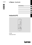
Industrial PC
Ä.Kò;ä
LDCDS−ELx7xx
.Kò;
Betriebsanleitung
Operating Instructions
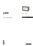
Embedded Line Panel−PC
EL 870 − EL 9700
Einbau−Panel−PC mit TFT−Display
Panel PC with TFT display
Lesen Sie zuerst diese Anleitung, bevor Sie mit den Arbeiten beginnen!
Beachten Sie die enthaltenen Sicherheitshinweise.
Please read these instructions before you start working!
Follow the enclosed safety instructions.
0
1
2
3
Power
Fail
Status
F1
F2
+
F3
0
4
-
1
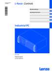
ELx7xx−001
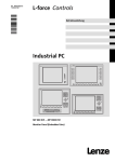
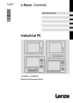
Elemente
Pos.
Beschreibung
Panel−PC (hier EL 5700)
Frontseitiger USB−Anschluss (Option)
Schraubspanner
DVD−Laufwerk (Option)
Frontseitige Bedien− und Anzeigeelemente
Informationen zur Gültigkeit
Diese Anleitung ist gültig für
ƒ EL 870
ƒ EL 1700, EL 1700s
ƒ EL 1750, EL 1750s
ƒ EL 2700
ƒ EL 2750
ƒ EL 5700
ƒ EL 5720
ƒ EL 5750
ƒ EL 5770
ƒ EL 9700
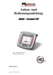
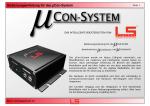
Identifikation
Lenze
D-40667 Meerbusch
P/N
107AT12345
107AT12345
C
UL
R
US LISTED
File Exxxxxx
IND. CONT. EQ.
14ZZ
certified
DVIUSB−012
4
Typbezeichnung
Typschlüssel/Bestellnummer
Technische Daten
Hardware−/Firmware−Version
Materialnummer (kundenspezifisch)
Seriennummer als Barcode
Hersteller
Zertifizierung
Handzeichen Prüfer
LDCDS−ELx7xx DE/EN 4.0
Typenschlüssel
34xx
x
x
x
x
x
x
xx
x
Gerätetyp
3400 = EL 870
3401 = EL 1700
3402 = EL 1700s
3403 = EL 2700
3404 = EL 5700
3405 = EL 9700
3406 = EL 5720
3407 = EL 1750
3408 = EL 1750s
3409 = EL 2750
3410 = EL 5750
3411 = EL 5770 (Tastatur deutsch)
3412 = EL 5770 (Tastatur englisch)
Front
1 = Glasscheibe
2 = Touchscreen
X = kundenspezifisch
USB−Anschluss, frontseitig
0 = ohne
1 = mit
Prozessor, lüfterlos
L = AMD Geode LX800 / 500 MHz
8 = Mobile Intelâ Celeron M 600 MHz
9 = Mobile Intelâ Celeron M 1 GHz
Prozessor, "Smart Cool"
G = AMD Geode LX800 / 500 MHz
H = Mobile Intelâ Celeron M 600 MHz
K = Mobile Intelâ Celeron M 1 GHz
D = Mobile Intelâ Celeron M 1,5 GHz
E = Mobile Intelâ Celeron M 1,8 GHz
F = Intelâ Coreä Duo 1,66 GHz
Arbeitsspeicher
3 = 256 MB
4 = 512 MB
5 = 1024 MB
Massenspeicher
1 = Steckplatz für Compact Flash
2 = zusätzlich Festplatte 60 GB
3 = zusätzlich Festplatte 40 GB (erw. Temp.−Bereich)
4 = zusätzlich Festplatte 40 GB (für Dauerbetrieb)
DVD−Laufwerk
0 = ohne
1 = DVD/CD lesen
2 = DVD/CD lesen, CD schreiben
3 = DVD/CD lesen und schreiben
PCI−Modul−Karte (Karte 1/2)
0 = ohne
1 = MC−ETH Ethernet 100/1000 MBit
5 = MC−PBM PROFIBUS Master
6 = MC−PBS PROFIBUS Slave
8 = MC−PND ProfiNet Device
B = MC−CAN2 2−fach CAN mit PCAN Light−Lizenz
C = MC−MPI
USV
0 = ohne
1 = mit ACU USV Control Unit
LDCDS−ELx7xx DE/EN 4.0
5
Dokumenthistorie
Materialnummer
Version
Beschreibung
13215987
1.0
10/2007
TD29
Erstausgabe
13240552
2.0
03/2008
TD29
Zulässige Umgebungstemperatur für Celeron M, 1,8 GHz
geändert
13297870
3.0
06/2009
TD29
Überarbeitung
13297870
3.1
07/2011
TD29
UL−Approbation
4.0
01/2013
TD29
EL 5720: Funktions− und Sondertastenbelegung geändert
.Kò;
0Abb. 0Tab. 0
Tipp!
Dokumentationen und Software−Updates zu weiteren Lenze Produkten finden Sie im
Internet im Bereich "Services & Downloads" unter
http://www.Lenze.com
6
LDCDS−ELx7xx DE/EN 4.0
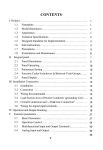
Inhalt
1
2
3
4
5
i
Sicherheitshinweise . . . . . . . . . . . . . . . . . . . . . . . . . . . . . . . . . . . . . . . . . . . . . . . . . . . . . . . .
9
1.1
Verwendete Hinweise . . . . . . . . . . . . . . . . . . . . . . . . . . . . . . . . . . . . . . . . . . . . . . . . .
9
1.2
Allgemeine Sicherheitshinweise . . . . . . . . . . . . . . . . . . . . . . . . . . . . . . . . . . . . . . . .
11
Gerätebeschreibung . . . . . . . . . . . . . . . . . . . . . . . . . . . . . . . . . . . . . . . . . . . . . . . . . . . . . . .
12
2.1
Lieferumfang . . . . . . . . . . . . . . . . . . . . . . . . . . . . . . . . . . . . . . . . . . . . . . . . . . . . . . . .
12
2.2
Bestimmungsgemäße Verwendung . . . . . . . . . . . . . . . . . . . . . . . . . . . . . . . . . . . . .
13
2.3
Grundgeräte . . . . . . . . . . . . . . . . . . . . . . . . . . . . . . . . . . . . . . . . . . . . . . . . . . . . . . . . .
14
2.4
Baseboard . . . . . . . . . . . . . . . . . . . . . . . . . . . . . . . . . . . . . . . . . . . . . . . . . . . . . . . . . . .
16
2.5
ACU USV Control Unit (Option) . . . . . . . . . . . . . . . . . . . . . . . . . . . . . . . . . . . . . . . . .
17
2.6
Software . . . . . . . . . . . . . . . . . . . . . . . . . . . . . . . . . . . . . . . . . . . . . . . . . . . . . . . . . . . .
2.6.1
Betriebssystem (Zubehör) . . . . . . . . . . . . . . . . . . . . . . . . . . . . . . . . . . . . . .
2.6.2
Lüfterüberwachung mit "Smart Cool" und "FAN−Service" (Option) . . . .
18
18
19
Technische Daten . . . . . . . . . . . . . . . . . . . . . . . . . . . . . . . . . . . . . . . . . . . . . . . . . . . . . . . . . .
21
3.1
Allgemeine Daten und Einsatzbedingungen
.............................
21
3.2
Elektrische Daten . . . . . . . . . . . . . . . . . . . . . . . . . . . . . . . . . . . . . . . . . . . . . . . . . . . . .
24
3.3
Mechanische Daten
.................................................
26
Mechanische Installation . . . . . . . . . . . . . . . . . . . . . . . . . . . . . . . . . . . . . . . . . . . . . . . . . . .
28
4.1
Wichtige Hinweise . . . . . . . . . . . . . . . . . . . . . . . . . . . . . . . . . . . . . . . . . . . . . . . . . . . .
28
4.2
Einbauausschnitt . . . . . . . . . . . . . . . . . . . . . . . . . . . . . . . . . . . . . . . . . . . . . . . . . . . . .
29
4.3
Montageschritte . . . . . . . . . . . . . . . . . . . . . . . . . . . . . . . . . . . . . . . . . . . . . . . . . . . . .
4.3.1
Panel PC EL 870 / EL 1700(s) / EL 1750(s) . . . . . . . . . . . . . . . . . . . . . . . . . .
4.3.2
Panel PC EL 2700 / EL 2750 / EL 5700 / EL 5720 / EL 5750 / EL 5770 /
EL 9700 . . . . . . . . . . . . . . . . . . . . . . . . . . . . . . . . . . . . . . . . . . . . . . . . . . . . .
30
30
Elektrische Installation . . . . . . . . . . . . . . . . . . . . . . . . . . . . . . . . . . . . . . . . . . . . . . . . . . . . .
33
5.1
Wichtige Hinweise . . . . . . . . . . . . . . . . . . . . . . . . . . . . . . . . . . . . . . . . . . . . . . . . . . . .
33
5.2
Versorgungsspannung anschließen . . . . . . . . . . . . . . . . . . . . . . . . . . . . . . . . . . . . .
5.2.1
Netzanschluss (X101) . . . . . . . . . . . . . . . . . . . . . . . . . . . . . . . . . . . . . . . . .
5.2.2
USV−PACK−Anschluss (X102) . . . . . . . . . . . . . . . . . . . . . . . . . . . . . . . . . . . .
35
35
36
5.3
Externe Geräte anschließen . . . . . . . . . . . . . . . . . . . . . . . . . . . . . . . . . . . . . . . . . . . .
5.3.1
PS/2−Schnittstelle (X108) . . . . . . . . . . . . . . . . . . . . . . . . . . . . . . . . . . . . . .
5.3.2
Serielle Schnittstelle (X103) . . . . . . . . . . . . . . . . . . . . . . . . . . . . . . . . . . . .
5.3.3
Ethernet−Schnittstelle (X107) . . . . . . . . . . . . . . . . . . . . . . . . . . . . . . . . . . .
5.3.4
USB−Schnittstelle (X104, X105, X106) . . . . . . . . . . . . . . . . . . . . . . . . . . . .
5.3.5
PCI Module Card−Schnittstelle . . . . . . . . . . . . . . . . . . . . . . . . . . . . . . . . . .
5.3.6
USB−Schnittstelle, frontseitig (Option) . . . . . . . . . . . . . . . . . . . . . . . . . . .
37
37
37
37
37
37
38
LDCDS−ELx7xx DE/EN 4.0
31
7
i
6
7
8
8
Inhalt
Bedienung . . . . . . . . . . . . . . . . . . . . . . . . . . . . . . . . . . . . . . . . . . . . . . . . . . . . . . . . . . . . . . .
39
6.1
Wichtige Hinweise . . . . . . . . . . . . . . . . . . . . . . . . . . . . . . . . . . . . . . . . . . . . . . . . . . . .
39
6.2
Bedien− und Anzeigeelemente . . . . . . . . . . . . . . . . . . . . . . . . . . . . . . . . . . . . . . . . . .
6.2.1
Panel−PC EL 870 / EL 1700 / EL 1700s / EL 2700 / EL 5700 / EL 9700 . . . .
6.2.2
Panel−PC EL 5720 . . . . . . . . . . . . . . . . . . . . . . . . . . . . . . . . . . . . . . . . . . . . .
6.2.3
Panel−PC EL 1750 / EL 1750s / EL 2750 / EL 5750 . . . . . . . . . . . . . . . . . . .
6.2.4
Panel−PC EL 5770 . . . . . . . . . . . . . . . . . . . . . . . . . . . . . . . . . . . . . . . . . . . . .
40
40
41
42
44
Wartung . . . . . . . . . . . . . . . . . . . . . . . . . . . . . . . . . . . . . . . . . . . . . . . . . . . . . . . . . . . . . . . . .
46
7.1
Kontrollarbeiten . . . . . . . . . . . . . . . . . . . . . . . . . . . . . . . . . . . . . . . . . . . . . . . . . . . . . .
47
7.2
Reinigung . . . . . . . . . . . . . . . . . . . . . . . . . . . . . . . . . . . . . . . . . . . . . . . . . . . . . . . . . . .
47
7.3
Instandsetzung . . . . . . . . . . . . . . . . . . . . . . . . . . . . . . . . . . . . . . . . . . . . . . . . . . . . . .
7.3.1
PC−Gehäuse demontieren . . . . . . . . . . . . . . . . . . . . . . . . . . . . . . . . . . . . . .
7.3.2
PC−Gehäuse montieren . . . . . . . . . . . . . . . . . . . . . . . . . . . . . . . . . . . . . . . .
7.3.3
Batterie wechseln . . . . . . . . . . . . . . . . . . . . . . . . . . . . . . . . . . . . . . . . . . . . .
7.3.4
Sicherung wechseln . . . . . . . . . . . . . . . . . . . . . . . . . . . . . . . . . . . . . . . . . . .
48
48
50
52
53
Stichwortverzeichnis . . . . . . . . . . . . . . . . . . . . . . . . . . . . . . . . . . . . . . . . . . . . . . . . . . . . . . .
54
LDCDS−ELx7xx DE/EN 4.0
Sicherheitshinweise
1
Verwendete Hinweise
1
Sicherheitshinweise
1.1
Verwendete Hinweise
Um auf Gefahren und wichtige Informationen hinzuweisen, werden in dieser Dokumentation folgende Piktogramme und Signalwörter verwendet:
Sicherheitshinweise
Aufbau der Sicherheitshinweise:
Gefahr!
(kennzeichnet die Art und die Schwere der Gefahr)
Hinweistext
(beschreibt die Gefahr und gibt Hinweise, wie sie vermieden werden kann)
Piktogramm und Signalwort
Bedeutung
Gefahr!
Gefahr von Personenschäden durch gefährliche elektrische
Spannung
Hinweis auf eine unmittelbar drohende Gefahr, die den Tod oder
schwere Verletzungen zur Folge haben kann, wenn nicht die
entsprechenden Maßnahmen getroffen werden.
Gefahr!
Gefahr von Personenschäden durch eine allgemeine Gefahrenquelle
Hinweis auf eine unmittelbar drohende Gefahr, die den Tod oder
schwere Verletzungen zur Folge haben kann, wenn nicht die
entsprechenden Maßnahmen getroffen werden.
Stop!
Gefahr von Sachschäden
Hinweis auf eine mögliche Gefahr, die Sachschäden zur Folge
haben kann, wenn nicht die entsprechenden Maßnahmen getroffen werden.
Anwendungshinweise
Piktogramm und Signalwort
LDCDS−ELx7xx DE/EN 4.0
Bedeutung
Hinweis!
Wichtiger Hinweis für die störungsfreie Funktion
Tipp!
Nützlicher Tipp für die einfache Handhabung
Verweis auf andere Dokumentation
9
1
Sicherheitshinweise
Verwendete Hinweise
Spezielle Sicherheitshinweise und Anwendungshinweise für UL und UR
Piktogramm und Signalwort
Bedeutung
Warnings!
Sicherheitshinweis oder Anwendungshinweis für den Betrieb
eines UL−approbierten Geräts in UL−approbierten Anlagen.
Möglicherweise wird das Antriebssystem nicht UL−gerecht betrieben, wenn nicht die entsprechenden Maßnahmen getroffen
werden.
Warnings!
Sicherheitshinweis oder Anwendungshinweis für den Betrieb
eines UR−approbierten Geräts in UL−approbierten Anlagen.
Möglicherweise wird das Antriebssystem nicht UL−gerecht betrieben, wenn nicht die entsprechenden Maßnahmen getroffen
werden.
10
LDCDS−ELx7xx DE/EN 4.0
Sicherheitshinweise
1
Allgemeine Sicherheitshinweise
1.2
Allgemeine Sicherheitshinweise
ƒ
Das Gerät darf nur von qualifiziertem Fachpersonal installiert und gewartet werden,
das mit den geltenden nationalen Normen vertraut ist.
ƒ
Das Gerät ist eine Einrichtung der Klasse A. Diese Einrichtung kann im Wohnbereich
Funkstörungen verursachen. In diesem Fall kann vom Betreiber verlangt werden,
angemessene Maßnahmen durchzuführen und dafür aufzukommen.
ƒ
Ein Touchscreen entspricht nicht der Ergonomierichtlinie ZH 1/618 und ist daher nur
für kurzzeitige Eingaben und Kontrollfunktionen ausgelegt. Schließen Sie bei
längeren Eingaben eine externe Tastatur an.
ƒ
Im Fehlerfall muss sofort der Versorgungsstecker gezogen werden. Anschließend
ist das Gerät an den Hersteller zu schicken. Die Adresse finden Sie auf dem
Rückumschlag dieser Dokumentation. Bei Rücksendung bitte die
Originalverpackung verwenden!
ƒ
Flachbaugruppen, die durch Kurzschluss oder elektrostatische Entladungen (ESD)
beschädigt werden können, sind vorschriftsmäßig zu handhaben.
ƒ
Das BIOS des Mainboards ist werksseitig konfiguriert. Nach einem Update des BIOS
sind Funktionsstörungen nicht ausgeschlossen. Wenden Sie sich bitte an unseren
Service.
ƒ
Zur Entsorgung des Geräts, zerlegen Sie es in seine Einzelteile. Geben Sie Metalle,
Kunststoffe und Leiterplatten in die Wiederverwertung. Beachten Sie die örtlichen
Bestimmungen.
LDCDS−ELx7xx DE/EN 4.0
11
2
Gerätebeschreibung
Lieferumfang
2
Gerätebeschreibung
2.1
Lieferumfang
Anzahl Bezeichnung
1
Embedded Line Panel−PC EL xxxx
8
8
4
6
5
6
1
Schraubspanner
EL 870
EL 1700, EL 1700s, EL 1750, EL 1750s
EL 2700
EL 2750, EL 5700, EL 5720, EL 5750
EL 5770
EL 9700
Phönix Combicon−Stecker MC1,5/2−STF−3,81
1
Treiber−CD
1
Handbuch−CD
1
Testbericht
1
Gerätepass
Hinweis!
Überprüfen Sie nach Erhalt der Lieferung sofort, ob der Lieferumfang mit den
Warenbegleitpapieren übereinstimmt. Für nachträglich reklamierte Mängel
übernehmen wir keine Gewährleistung.
Reklamieren Sie
ƒ erkennbare Transportschäden sofort beim Anlieferer.
ƒ erkennbare Mängel / Unvollständigkeit sofort bei der zuständigen
Lenze−Vertretung.
12
LDCDS−ELx7xx DE/EN 4.0
Gerätebeschreibung
2
Bestimmungsgemäße Verwendung
2.2
Bestimmungsgemäße Verwendung
Der Panel−PC wird bestimmungsgemäß verwendet, wenn er ausschließlich zur Umsetzung von Bedienkonzepten oder zur Darbietung von Informationen in gewöhnlichen industriellen und gewerblichen Bereichen eingesetzt wird. Eine andere oder darüber hinaus gehende Verwendung ist nicht zulässig.
Eine nichtbestimmungsgemäße Verwendung liegt auch bei einem Gebrauch vor, der verhängnisvolle Risiken oder Gefahren birgt, die ohne Sicherstellung außergewöhnlich hoher
Sicherheitsmaßnahmen zu Tod, Verletzung oder Sachschaden führen können.
Der Panel−PC darf insbesondere nicht verwendet werden ...
ƒ
in privaten Bereichen.
ƒ
in explosionsgefährdeten Bereichen.
ƒ
in Bereichen mit schädlichen Gasen, Ölen, Säuren, Strahlungen usw.
ƒ
in Anwendungen, bei denen Schwingungs− und Stoßbelastungen auftreten, die
über die Anforderungen der EN 50178 hinausgehen.
ƒ
zur Wahrnehmung von Sicherheitsfunktionen, zum Beispiel
– in der Flugsicherung / in Flugleitsystemen
– für die Überwachung/Steuerung von Kernreaktionen
– für die Überwachung/Steuerung von Massentransportmitteln
– für die Überwachung/Steuerung von medizinischen Systemen
– für die Überwachung/Steuerung von Waffensystemen
Für die Gewährleistung des Personen− und Sachschutzes müssen übergeordnete Sicherheitssysteme eingesetzt werden!
LDCDS−ELx7xx DE/EN 4.0
13
2
Gerätebeschreibung
Grundgeräte
2.3
Grundgeräte
Eigenschaften
ƒ
Ausführung
– PC−Gehäuse aus Stahlblech, bei passiver Kühlung z. T. aus Aluminium
– Frontrahmen aus eloxiertem und matt gebeiztem Aluminium
– Front aus Polyesterfolie
ƒ
Montage
– Zum Einbau in Schaltschränke, Maschinenverkleidungen und Schalttafeln
ƒ
Elektrische Versorgung
– Phönix−Combicon−Buchse (24 V DC)
– Lithium−Batterie zur Pufferung der Real−Time−Clock (RTC)
ƒ
Rechner−Einheit
– ETX−Modul mit CPU ( Dokumentation zum ETX−Modul auf der CD)
ƒ
Externe Schnittstellen
– 1 x PS/2
– 1 x LAN (Ethernet)
– 3 x USB Typ A (V 2.0)
– 1 x Seriell (RS232)
– 2 x PCI Module Card Slot für MC−Feldbusmodule
– 1 x Compact Flash−Steckplatz (Typ I und II; nicht bei Intelâ Core Duo−Prozessor)
Optionen
14
ƒ
ACU USV Control Unit
ƒ
2,5"−Festplatte (IDE)
ƒ
DVD−Laufwerk (IDE)
ƒ
PCI−Modul−Karte
ƒ
Frontseitiger USB−Anschluss Typ A (V2.0)
ƒ
DVI/USB−Extender
LDCDS−ELx7xx DE/EN 4.0
Gerätebeschreibung
2
Grundgeräte
Übersicht
Panel−PC EL 870 / EL 1700 / EL 1700s / EL 2700 / EL 5700 / EL 9700
l
EL 870: 8"−VGA−Touchscreen
EL 1700: 10,4"−VGA−Touchscreen
EL 1700s: 10,4"−SVGA−Touchscreen
EL 2700: 12,1"−SVGA−Touchscreen
EL 5700: 15"−XGA−Touchscreen
EL 9700: 19"−SXGA−Touchscreen
l 3 frei belegbare Funktionstasten
Power
Fail
Status
F1
F2
+
F3
-
CS57x0−026
Panel−PC EL 5720
S1
l
l
l
S8
S2
S9
S3
S10
S4
S11
S5
S12
S6
S13
S7
S14
+
15"−XGA−Touchscreen
12 frei belegbare Funktionstasten
14 frei belegbare Sondertasten
-
Power
Fail
Status
F1
Esc
F2
F3
F4
F5
F6
F7
F8
F9
F10
F11
F12
Enter
ELx7xx−002
Panel−PC EL 1750 / EL 1750s / EL 2750 / EL 5750
l
A
B
8
7
E
4
C
F
G
J
M
.
+
K
L
3
2
0
H
6
5
I
1
N
*
O
,
EL 1750: 10,4"−VGA−Touchscreen
EL 1750s: 10,4"−SVGA−Touchscreen
EL 2750: 12,1"−SVGA−Touchscreen
EL 5750: 15"−XGA−Touchscreen
l 12 frei belegbare Funktionstasten
l Nummerblock, Steuertasten, Ebenenumschaltung
Alpha
D
-
9
P
/
Pg Up
Power
Fail
Status
Home
End
Pg Dn
Bs
Q
F1
+
R
F2
-
S
F3
T
F4
U
F5
V
F6
W
F7
X
F8
Y
F9
Z
\
@
F10
F11
F12
Ins
Del
Ctrl
Alt
Esc
Menu
Shift
Space
Alpha
Enter
CS57x0−028
LDCDS−ELx7xx DE/EN 4.0
15
2
Gerätebeschreibung
Baseboard
Panel−PC EL 5770
/
(
7
l
l
l
15"−XGA−Touchscreen
12 frei belegbare Funktionstasten
Nummerblock, Steuertasten, Ebenenumschaltung
Alpha
l MF/2−Tastatur
)
8
-
9
$
&
4
5
§
"
1
2
=
3
>
<
,
0
+
6
!
*
/
|
Power
Fail
Status
Bs
Alt Gr
F1
+
-
F2
F3
Q
Alt
W
F4
E
@
A
S
Y
€
F5
R
D
X
F6
T
C
Z
G
F
V
F7
U
H
B
F8
I
J
N
O
K
M
F9
P
L
;
,
μ
F10
Ü
Ä
Ö
:
.
_
-
F11
F12
Einfg
Entf
Pos 1
Ende
Bild
Bild
Strg
Esc
*
+ ~
?
ß \
Enter
Space
CS57x0−029
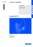
2.4
Baseboard
FLAT-PANEL-LVDS
FAN0
VGA
POWER
HARDDISK / CD-ROM
X4
X3
0
EPC50
6
1
5
FAN3
FAN2
2
20
BLIGHT
X1
USB-μCON
X2
3
T4A
FAN1
CF-CARD
USB_C
USB_A
RESET
USB_B
ACCU
POWER
RT
GE
GN
MOUSE
COM1
1
F1
2
4
19
CR2450
CS57x0−018
16
Festplatte (Option)
ETX−Modul (weitere Informationen finden Sie in der ETX−Modul−Dokumentation auf der
Handbuch−CD)
Batterie ( 52)
ACU USV Contol Unit ( 17)
Sicherung ( 53)
PCI Module Card Slot
IDE−Schnittstelle
LDCDS−ELx7xx DE/EN 4.0
Gerätebeschreibung
2
ACU USV Control Unit (Option)
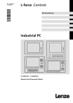
2.5
ACU USV Control Unit (Option)
Die optionale ACU USV Control Unit in Verbindung mit einem Batterie− oder Kondensatorpack erweitert den Industrie−PC um eine USV−Funktionalität.
Die ACU USV Control Unit ist entweder werksseitig vorgerüstet oder kann durch Lenze−Service−Personal nachgerüstet werden.
Eigenschaften der ACU USV Control Unit
mit Batteriepack (ACCU−PACK)
mit Kondensatorpack (CAPS−PACK)
l
l
Überbrückt einen kurzzeitigen Netzausfall oder
Netzschwankungen und fährt den PC herunter.
l Software−basierte Konfiguration
l Dokumentation zum Batteriepack
Bietet die Möglichkeit der Datensicherung bei Netzausfall.
l Nicht für Windows XP geeignet.
l Software−basierte Konfiguration
l Dokumentation zum Kondensatorpack
EPC50
k
UCA
FAN3
S
FAN2
3
USB-μCON
BLIGHT
CR2450
20
ac
19
-P
1
0
CU
2
AC
US
Be
fo
in re
st
ru open
ct
io ing,
n
ma re
nu ad
al
. the
V
F1
T4A
ACCU
RESET
1
2
POWER
4
CS57x0−042
LDCDS−ELx7xx DE/EN 4.0
Batteriepack 2700 oder Kondensatorpack 2701 (Zubehör)
Anschlusskabel (im Lieferumfang des Batteriepacks/Kondensatorpacks)
Anschluss am Industrie−PC
ACU USV Control Unit
Baseboard
17
2
Gerätebeschreibung
Software
Betriebssystem (Zubehör)
2.6
Software
2.6.1
Betriebssystem (Zubehör)
Folgende Betriebssysteme sind auf dem Industrie−PC lauffähig und werden, je nach Bestellung, vorinstalliert auf einem Speichermedium ausgeliefert:
Betriebssystem
Beschreibung
Lieferbar auf Speichermedium
Windows XPâ Multilanguage
l
l
l
Windows XPâ Embedded
l
Windows CEâ 5.0
l
1)
Professional mit SP2 oder höher
Vorinstallierte Sprachen: englisch, deutsch,
französisch, spanisch, portugiesisch (Brasilien), chinesisch (VR China)
Festplatte 1)
Komponentenversion von Windows XPâ
l Festplatte
Professional, bei der die benötigten Softwa- l Compact Flash−Card
rekomponenten und Treiber werksseitig
vorgegeben sind.
l Vorinstallierte Sprachen: englisch, deutsch
l Für die diversen Prozessor−Typen sind angepasste Image−Dateien lieferbar.
Echtzeitfähiges Betriebssystem mit gerinl Compact Flash−Card
gem Resourcen−Bedarf
l Für die diversen Prozessor−Typen sind angepasste Installationen erhältlich (nicht für
Coreä Duo).
Der Industrie−PC muss mit einer Festplatte ausgestattet sein.
Hinweis!
Weitere Informationen finden Sie in der Dokumentation zu Ihrem
Betriebssystem.
18
LDCDS−ELx7xx DE/EN 4.0
Gerätebeschreibung
2
Software
Lüfterüberwachung mit "Smart Cool" und "FAN−Service" (Option)
2.6.2
Lüfterüberwachung mit "Smart Cool" und "FAN−Service" (Option)
"Smart Cool"
Zwangsbelüftete Industrie−PCs sind grundsätzlich mit einer Temperaturüberwachung
ausgestattet, die über die Software "Smart Cool" gesteuert wird.
Ein Temperatursensor misst die Temperatur im Gehäuse des Industrie−PCs. Bei Überschreiten einer vorgegebenen Temperatur schaltet "Smart Cool" die Lüfter des Industrie−PCs ein;
wenn die Temperatur wieder gefallen ist, schaltet "Smart Cool" sie wieder aus.
Welche Lüfter im Indurstrie−PC von der Software gesteuert wird und bei welcher Temperatur die Lüfter anlaufen, ist entsprechend der eingesetzten PC−Komponenten werksseitig
vorgegeben.
Die Software startet automatisch mit dem Betriebssystem und läuft dann im Hintergrund.
Die Bedienoberfläche von "Smart Cool" öffnen Sie in der Systemsteuerung über einen
gleichnamigen Eintrag. Auf der Bedienoberfläche können Sie einen der folgenden Zustände über Optionsfelder zuweisen:
Zustand "Smart−Cool": Die Temperaturüberwachung ist aktiv und arbeitet wie oben beschrieben (Werkseinstellung).
Zustand "FAN on": Alle Lüfter des Industrie−PC laufen ständig.
Der zugewiesene Zustand bleibt auch nach einem Neustart bestehen.
"FAN−Service"
Der "FAN−Service" ist ein Dienst, der zusammen mit "Smart Cool" installiert wird. Er überwacht die Lüfter des Industrie−PCs und meldet (Windows−Fenster) bzw. protokolliert (Log−
Datei) folgende Systemzustände:
ƒ
Lüfter−Ausfall
ƒ
Fehlerhafte oder leere Pufferbatterie
Der "FAN−Service"−Dienst läuft im Hintergrund und besitzt keine Bedienoberfläche.
Die Protokolldatei "LogFanService.txt" finden Sie unter ...
ƒ
Windows XP (Embedded) im "Smart Cool"−Programmordner
(z. B. "x:\Programme\Lenze\SmartCool\)
ƒ
Windows CE im Ordner "x:\Storage\DeviceScanner\"
Hinweis!
Damit die Protokolldatei nicht zu lang wird, werden deren Daten in die Datei
"LogFanService.bak" verschoben, sobald die Dateigröße 100 kB übersteigt.
LDCDS−ELx7xx DE/EN 4.0
19
2
Gerätebeschreibung
Software
Lüfterüberwachung mit "Smart Cool" und "FAN−Service" (Option)
Hinweise zur Installation
Wenn Sie das Betriebssystem vorinstalliert auf einem Speichermedium von Lenze bezogen
haben, ist die Software für die Lüfterüberwachung bereits installiert.
In anderen Fällen finden Sie die Software auf der Treiber−CD zu Ihrem Industrie−PC. Die Installation unterscheidet sich bei den Betriebssystemen:
Windows XP: Starten Sie das Setup−Programm auf der Treiber−CD und folgen Sie den Anweisungen des Setup−Assistenten. Nach erfolgreicher Installation muss der Industrie−PC
neu gestartet werden.
Windows CE: Ergänzen Sie folgende Zeilen in der Autostart−Datei von Windows CE:
open "wceload.exe" "/noaskdest/noui/nouninstall
\Storage\DeviceScanner\SmartCoolCab.cab"
\Storage\DeviceScanner\FANServiceCE.exe
Nach einem Neustart wird die selbstextrahierende CAB−Datei ausgeführt.
20
LDCDS−ELx7xx DE/EN 4.0
Technische Daten
3
Allgemeine Daten und Einsatzbedingungen
3
Technische Daten
3.1
Allgemeine Daten und Einsatzbedingungen
Konformität und Approbation
Konformität
CE
EN 61000 6−4
EN 61000 6−2
EMV−Richtlinie, Klasse A, Industriebereich
UL 508
CSA C22.2
Programmable Controllers (File−No. E236341)
Approbation
UL
Personenschutz und Geräteschutz
Sicherheit
VDE0805 (EN60950),
VDE0870, UL
Schutzart
IP65 (Frontseite) / IP20 (Rückseite)
Schutzklasse
3
Montagebedingungen
Einbauort
Schaltschrank
Einbaulage
Anschlüsse unten
Umgebungsbedingungen
Klimatisch
Lagerung
−10 ... +60 °C
Transport
−10 ... +60 °C
Betrieb
abhängig von der Ausstattung ( 22)
Relative Luftfeuchte
10 ... 90 %, nicht kondensierend
Aufstellhöhe
< 3000 m üNN
Chemische Beständigkeit
Dekorfolie
Gehäuse
DIN 42115
Mechanische Belastbarkeit
Dekorfolie
Schaltelement
LDCDS−ELx7xx DE/EN 4.0
DIN 42115
max. 100 N
21
3
Technische Daten
Allgemeine Daten und Einsatzbedingungen
Hinweis!
Die Ausfallwahrscheinlichkeit eines elektronischen Bauteils wächst mit der
Umgebungstemperatur, der das Bauteil ausgesetzt ist. In Hinblick auf
Betriebsfähigkeit und Zuverlässigkeit ist der Gerätekühlung also besondere
Aufmerksamkeit zu schenken. Grundsätzlich sollte in jeder Applikation mit
Sorgfalt darauf geachtet werden, die Erwärmung des Gerätes so gering wie
möglich zu halten.
ƒ Wir empfehlen, zur Sicherstellung einer ausreichenden Wärmeabfuhr,
zwangsbelüftete Systeme mit "Smart Cool"−Lüftersteuerung einzusetzen.
Die Lüftersteuerung überwacht sowohl die Innentemperatur des Gerätes als
auch die Funktion des Lüfters. Bei Überschreiten einer vorgegebenen
Maximaltemperatur schaltet sie den Lüfter ein, bei Unterschreiten einer
Lüfter−Mindestdrehzahl meldet sie eine Störung.
ƒ Systeme mit einer passiven Kühlung über Kühlkörper sollten nur eingesetzt
werden, wenn eine ausreichende Konvektion ständig gewährleistet ist (z. B.
durch externe Lüfterbaugruppen in Schaltschränken oder bei Aufstellung
des Gerätes in klimatisierten Bereichen).
Zulässige Umgebungstemperaturen bei lüfterlosen Systemen
Grundgerät
l
l
l
bis 1 GB RAM
mit CF−Card
20−GB−Festplatte für erweiterten
Temperaturbereich
l
40−GB−Festplatte
Prozessor
l
40−GB−Festplatte für
Dauerbetrieb
(24/7) *
l
l
DVD−Laufwerk (nur lesen)
DVD−Laufwerk (lesen
und schreiben)
[°C]
AMD Geode
LX800 / 500 MHz
Mobile Intelâ
Celeron M
600 MHz
Mobile Intelâ
Celeron M 1 GHz
*
22
0 ... 45
5 ... 45
5 ... 40
0 ... 40
5 ... 45
5 ... 40
5 ... 40
Wir empfehlen, die Festplatte nach 30.000 Stunden Betrieb oder nach 5 Jahren auszutauschen.
LDCDS−ELx7xx DE/EN 4.0
Technische Daten
3
Allgemeine Daten und Einsatzbedingungen
Zulässige Umgebungstemperaturen bei Systemen mit "Smart Cool"−Kühlung
Grundgerät
l
l
l
bis 1 GB RAM
mit CF−Card
20−GB−Festplatte für erweiterten
Temperaturbereich
l
40−GB−Festplatte
Prozessor
l
40−GB−Festplatte für
Dauerbetrieb
(24/7) *
l
DVD−Laufwerk (nur lesen)
l
DVD−Laufwerk (lesen
und schreiben)
[°C]
AMD Geode
LX800 / 500 MHz
Mobile Intelâ
Celeron M
600 MHz
Mobile Intelâ
Celeron M 1 GHz
0 ... 50
Mobile Intelâ
Celeron M
1,5 GHz
5 ... 45
5 ... 45
5 ... 45
5 ... 40
Mobile Intelâ
Celeron M
1,8 GHz
Intelâ Coreä
Duo 1,66 GHz bei
max. 50 % CPU−
Auslastung 2)
Intelâ Coreä
Duo 1,66 GHz bei
max. 100 % CPU−
Auslastung 2)
1)
2)
0 ... 45
0 ... 40
5 ... 40
5 ... 40
5 ... 40
Wir empfehlen, die Festplatte nach 30.000 Stunden Betrieb oder nach 5 Jahren auszutauschen.
Die CPU−Auslastung kann über den Windows−Task−Manager ermittelt werden (Register "Systemleistung")
LDCDS−ELx7xx DE/EN 4.0
23
3
Technische Daten
Elektrische Daten
3.2
Elektrische Daten
Versorgung
Gerät
Sicherung
Spannung
Strom bei 24 V 1)
[DC V]
[A]
Pufferbatterie
Typ
Typ
Lebensdauer
[Jahre]
EL 870
EL 1700
EL 1700s
1,3
EL 1750
EL 1750s
EL 2700
EL 2750
24 (+18 ... 30) 2)
53
1,2
52
> 6 (25 °C)
EL 5700
EL 5720
1,4
EL 5750
EL 5770
EL 9700
1)
2)
2,1
gemessen mit Celeron M600−CPU und CF−Card
mit ACU USV Control Unit DC +20 ... 30 V
Bildschirm
Sichtgröße
Seitenverhältnis
[Zoll]
EL 870
EL 1700
EL 1750
EL 1700s
EL 1750s
24
Auflösung
Helligkeit
[Pixel]
[cd/m2]
8
640 x 480
Kontrast
MTBF
[h]
320
1 : 250
50.000
400
1 : 300
40.000
400
1 : 500
300
1 : 200
10,4
800 x 600
50.000
EL 2700
EL 2750
12,1
EL 5700
EL 5720
EL 5750
EL 5770
15
1024 x 768
250
1 : 550
40.000
EL 9700
19
1280 x 1024
300
1 : 700
50.000
4:3
LDCDS−ELx7xx DE/EN 4.0
Technische Daten
3
Elektrische Daten
Schnittstellen
Typ
Anschluss
COM
RS232
SUB−D−Stecker, 9 pol.
LAN
Ethernet 10/100 MBit
RJ45−Buchse
USB
2.0
Typ A−Buchse
PS/2
Standard
PS/2−Buchse, 6 pol.
PCI
PCI Module Card Slot
MC−Feldbusmodule
Compact Flash
Compact Flash Slot, Typ I und II (nicht bei Intelâ Core Duo−
Prozessor)
Wechselmedium
Hinweis!
Die technischen Daten zum ETX−Modul entnehmen Sie bitte der
ETX−Modul−Dokumentation auf der Handbuch−CD.
Betriebsspannung
Typ
max. Strom
Ladestrom im Arbeitsbereich
[mA]
[mA]
[V DC]
ACU−USV
1)
12 / 5
bei 5 V
bei 12 V
10
10 ... 600 1)
ca. 250
abhängig vom Laden
LDCDS−ELx7xx DE/EN 4.0
25
3
Technische Daten
Mechanische Daten
3.3
Mechanische Daten
Ausführungen und Gewichte
Frontrahmen / Gehäuse
Touchscreen
Masse *)
[kg]
EL 870
4,0
EL 1700
4,6
EL 1700s
4,6
EL 1750
5,0
EL 1750s
5,0
EL 2700
EL 2750
5,8
6,0
EL 5700
6,6
EL 5720
6,8
EL 5750
6,8
EL 5770
7,6
EL 9700
10,6
*)
26
Polyesterfolie
Aluminium/Stahlblech
Ohne optionales Zubehör (Festplatte, DVD−Laufwerk usw.)
LDCDS−ELx7xx DE/EN 4.0
Technische Daten
3
Mechanische Daten
CD/DVD
27.5
e
6
disc
b
a
CD/DVD
65
ELx7xx−003
Alle Maße in Millimeter.
Abmessungen
a
b
e
[mm]
EL 870
EL 1700
EL 1700s
EL 1750
EL 1750s
265
188
325
240
365
EL 2700
390
300
EL 2750
425
310
EL 5700
450
325
EL 5720
EL 5750
310 (7 HE)
483
399 (9 HE)
EL 5770
EL 9700
LDCDS−ELx7xx DE/EN 4.0
99
490
400
109
27
4
Mechanische Installation
Wichtige Hinweise
4
Mechanische Installation
4.1
Wichtige Hinweise
Die Installation darf nur von qualifiziertem Fachpersonal durchgeführt werden, das mit
den geltenden nationalen Normen vertraut ist.
Stop!
Empfindlicher Dichtring am Frontrahmen
Während der Montage liegt der Dichtring des Frontrahmens frei und kann
beschädigt werden.
Mögliche Folgen:
ƒ Die in den Technischen Daten genannte Schutzart wird nicht erreicht.
Schutzmaßnahmen:
ƒ Gehen Sie während der Montage sorgsam mit dem Dichtring um.
ƒ Schützen Sie den Dichtring vor UV−Strahlen.
ƒ Kontrollieren Sie den Dichtring jedesmal auf Unversehrtheit, bevor Sie das
Gerät montieren.
Stop!
Empfindliche Oberfläche des Touchscreens
Die Touchscreen−Folie ist sehr empfindlich gegen äußere Gewalteinwirkungen
und kann bei einer falschen Handhabung beschädigt werden.
Mögliche Folgen:
ƒ Die Touchscreen−Folie wird zerstört, zerkratzt oder wird stumpf.
Schutzmaßnahmen:
ƒ Vermeiden Sie den Kontakt der Touchscreen−Folie mit spitzen oder harten
Gegenständen.
ƒ Bedienen Sie den Touchscreen ausschließlich mit Ihren Fingern oder mit
einem Touchstift. Verwenden Sie niemals Gegenstände wie Kugelschreiber,
Bleistifte usw.
ƒ Entfernen Sie Schmutz und Fingerabdrücke unter Beachtung der Hinweise
im Kapitel "Reinigung" ( 47).
Hinweis!
Achten Sie bei der Wahl des Aufstellortes auf eine ergonomische Stellung des
Bildschirms, sowie auf Lichteinfall, das Reflektionen auf dem Bildschirm
verursachen könnte.
28
LDCDS−ELx7xx DE/EN 4.0
Mechanische Installation
4
Einbauausschnitt
4.2
Einbauausschnitt
a2
a1
1
b2
b5
b1
b4
b3
0
2
D
£5
ELx7xx−004
Einbauausschnitt
Kontur Frontrahmen
Schalttafel
Alle Maße in Millimeter.
Abmessungen
a1
a2
b1
b2
b3
b4
b5
D
[mm]
EL 870
246,0
−
188,0
−
−
−
−
−
305,0
−
228,0
−
−
−
−
−
343,0
−
228,0
−
−
−
−
−
EL 2700
340,0
351,0
228,0
122,0
122,0
0,0
−
EL 2750
375,0
386,0
228,0
122,0
122,0
0,0
−
EL 5700
400,0
411,0
313,0
134,5
134,5
0,0
−
452,0
462,4
299,0
104,9
104,6
15,7
−
EL 5770
452,0
462,4
388,2
149,3
149,3
15,9
−
EL 9700
438,0
451,0
386,0
172,0
172,0
60,0
60,0
EL 1700
EL 1700s
EL 1750
EL 1750s
EL 5720
EL 5750
LDCDS−ELx7xx DE/EN 4.0
6 x Æ5,5
8 x Æ4,5
29
4
Mechanische Installation
Montageschritte
Panel PC EL 870 / EL 1700(s) / EL 1750(s)
4.3
Montageschritte
4.3.1
Panel PC EL 870 / EL 1700(s) / EL 1750(s)
So gehen Sie bei der Montage vor:
1. Schneiden Sie den Einbauausschnitt in die Schalttafel ( 29).
2. Kontrollieren Sie, dass die Dichtung unter der Frontplatte korrekt liegt.
3. Setzen Sie das Gerät in den Einbauausschnitt, sichern Sie es mit einer Hand gegen
Herunterfallen.
4. Montieren Sie alle Schraubspanner wie folgt:
ELx7xx−011
– Stecken Sie den Schraubspanner, wie in der Abbildung gezeigt, in die Öffnung am
Gerätegehäuse.
– Drücken Sie den Schraubspanner nach unten, kippen Sie ihn in Richtung Gehäuse
und kontrollieren Sie, ob er korrekt eingerastet ist.
– Ziehen Sie den Schraubspanner mit einem Schraubendreher handfest an.
5. Kontrollieren Sie, dass das Gerät fest im Einbauausschnitt sitzt und die
Frontplattendichtung korrekt aufliegt.
– Ggf. Gerät bzw. Dichtung neu ausrichten.
– Wenn die Dichtung nicht korrekt sitzt, wird auf der Gerätevorderseite die
Schutzklasse IP65 nicht erreicht!
30
LDCDS−ELx7xx DE/EN 4.0
Mechanische Installation
4
Montageschritte
Panel PC EL 2700 / EL 2750 / EL 5700 / EL 5720 / EL 5750 / EL 5770 / EL 9700
4.3.2
Panel PC EL 2700 / EL 2750 / EL 5700 / EL 5720 / EL 5750 / EL 5770 / EL 9700
Hinweis!
Die Typen EL 5720, EL 5750 und EL 5770 können sowohl in beliebige
Schalttafeln als auch in 19"−Baugruppenträger nach DIN 41494 eingebaut
werden.
Schalttafel−Montage
So gehen Sie bei der Montage vor:
1. Schneiden Sie den Einbauausschnitt in die Schalttafel und bohren Sie die
Befestigungslöcher in die Schalttafel ( 29).
2. Kontrollieren Sie, dass die Dichtung unter der Frontplatte korrekt liegt.
3. Setzen Sie das Gerät in den Einbauausschnitt, sichern Sie es mit einer Hand gegen
Herunterfallen und schrauben Sie Muttern mit Scheiben auf die Gewindebolzen.
4. Montieren Sie alle Schraubspanner wie folgt:
ELx7xx−012
– Stecken Sie den Schraubspanner, wie in der Abbildung gezeigt, in die Öffnung am
Gerätegehäuse.
– Drücken Sie den Schraubspanner nach unten, kippen Sie ihn in Richtung Gehäuse
und kontrollieren Sie, ob er korrekt eingerastet ist.
– Ziehen Sie den Schraubspanner mit einem Schraubendreher handfest an.
5. Kontrollieren Sie, dass das Gerät fest im Einbauausschnitt sitzt und die
Frontplattendichtung korrekt aufliegt.
– Ggf. Gerät bzw. Dichtung neu ausrichten.
– Wenn die Dichtung nicht korrekt sitzt, wird auf der Gerätevorderseite die
Schutzklasse IP65 nicht erreicht!
LDCDS−ELx7xx DE/EN 4.0
31
4
Mechanische Installation
Montageschritte
Panel PC EL 2700 / EL 2750 / EL 5700 / EL 5720 / EL 5750 / EL 5770 / EL 9700
19"−Baugruppenträger−Montage (nur EL 5720, EL 5750 und EL 5770)
So gehen Sie bei der Montage vor:
1. Entfernen Sie am Frontrahmen die rückseitigen Gewindestifte.
2. Bohren Sie am Frontrahmen die rückseitigen Sacklöcher mit einem 6,5−mm−Bohrer
auf.
3. Setzen Sie das Gerät in den 19"−Baugruppenträger und schrauben Sie es fest.
32
LDCDS−ELx7xx DE/EN 4.0
Elektrische Installation
5
Wichtige Hinweise
5
Elektrische Installation
5.1
Wichtige Hinweise
Die Installation darf nur von qualifiziertem Fachpersonal durchgeführt werden, das mit
den geltenden nationalen Normen vertraut ist.
Stop!
Empfindlicher Dichtring am Frontrahmen
Während der Montage liegt der Dichtring des Frontrahmens frei und kann
beschädigt werden.
Mögliche Folgen:
ƒ Die in den Technischen Daten genannte Schutzart wird nicht erreicht.
Schutzmaßnahmen:
ƒ Gehen Sie während der Montage sorgsam mit dem Dichtring um.
ƒ Schützen Sie den Dichtring vor UV−Strahlen.
ƒ Kontrollieren Sie den Dichtring jedesmal auf Unversehrtheit, bevor Sie das
Gerät montieren.
Stop!
Empfindliche Oberfläche des Touchscreens
Die Touchscreen−Folie ist sehr empfindlich gegen äußere Gewalteinwirkungen
und kann bei einer falschen Handhabung beschädigt werden.
Mögliche Folgen:
ƒ Die Touchscreen−Folie wird zerstört, zerkratzt oder wird stumpf.
Schutzmaßnahmen:
ƒ Vermeiden Sie den Kontakt der Touchscreen−Folie mit spitzen oder harten
Gegenständen.
ƒ Bedienen Sie den Touchscreen ausschließlich mit Ihren Fingern oder mit
einem Touchstift. Verwenden Sie niemals Gegenstände wie Kugelschreiber,
Bleistifte usw.
ƒ Entfernen Sie Schmutz und Fingerabdrücke unter Beachtung der Hinweise
im Kapitel "Reinigung" ( 47).
LDCDS−ELx7xx DE/EN 4.0
33
5
Elektrische Installation
Wichtige Hinweise
Stop!
Kurzschluss und statische Entladungen
Das Gerät enthält Bauelemente, die bei Kurzschluss oder statischer Entladung
gefährdet sind.
Mögliche Folgen:
ƒ Das Gerät oder Teile davon werden zerstört.
Schutzmaßnahmen:
ƒ Bei allen Arbeiten am Gerät, immer Spannungsversorgung abschalten (Netz
und eine evtl. montierte USV). Dies gilt insbesondere:
– vor dem Öffnen des Gehäuses.
– vor dem Anschließen / Abziehen von Steckverbindern.
– vor dem Stecken / Ziehen von Modulen.
ƒ Alle Personen, die Flachbaugruppen handhaben, müssen ESD−Maßnahmen
berücksichtigen.
ƒ Kontakte von Steckverbindern dürfen nicht berührt werden.
ƒ Flachbaugruppen dürfen nur an kontaktfreien Stellen angefasst werden und
nur auf geeigneten Unterlagen abgelegt werden (z. B. auf ESD−Verpackung
oder leitfähigem Schaumstoff).
ƒ Flachbaugruppen dürfen nur in ESD−Verpackungen transportiert und
gelagert werden.
34
LDCDS−ELx7xx DE/EN 4.0
Elektrische Installation
5
Versorgungsspannung anschließen
Netzanschluss (X101)
5.2
Versorgungsspannung anschließen
5.2.1
Netzanschluss (X101)
Stop!
Kein Geräteschutz für zu hohe Eingangsspannung
Der Spannungseingang ist intern nicht abgesichert.
Mögliche Folgen:
ƒ Zerstörung des Gerätes bei zu hoher Eingangsspannung.
Schutzmaßnahmen:
ƒ Beachten Sie die maximal zulässige Eingangsspannung.
ƒ Sichern Sie das Gerät eingangsseitig fachgerecht gegen
Spannungsschwankungen und −spitzen ab.
Hinweis!
Der IPC fährt hoch, sobald die Versorgungsspannung anliegt.
Nachdem das Betriebssystem heruntergefahren ist, schaltet sich der IPC
automatisch aus. Zum Wiedereinschalten muss die Versorgungsspannung
kurz unterbrochen werden.
L1
N
PE
S
F
0
L1 N
+
~
1
0 V PE +24 V
+
=
0V
+ +24
Elx7xx−006
Panel−PC
Netzteil
Beschreibung
0V
U
Anschluss 24−V−Gleichstromversorgung
Anschlusstyp
Kabeltyp
3−pol. Phoenix CombiconBuchse
Kabel (Leiterquerschnitt max.
2,5 mm2) mit Phoenix Combicon−Stecker, MSTB 2,5 /
3−STF−5,08
M4−Gewindebolzen
Separater Erdungsleiter (min.
2,5 mm2) mit Ringkabelschuh
IPC001
Anschluss PE
IPC001
LDCDS−ELx7xx DE/EN 4.0
35
5
Elektrische Installation
Versorgungsspannung anschließen
USV−PACK−Anschluss (X102)
5.2.2
USV−PACK−Anschluss (X102)
Beschreibung
Anschluss Batteriepack
( LDCDS−2700) oder Kondensatorpack
( LDCDS−2701)
Anschlusstyp
Kabeltyp
2−pol. Buchse
EPC5x−ACU
(im Lieferumfang des Batterie− / Kondensatorpacks;
Länge 2,5 m; Verlängerungskabel lieferbar)
IPC001
36
LDCDS−ELx7xx DE/EN 4.0
Elektrische Installation
5
Externe Geräte anschließen
PS/2−Schnittstelle (X108)
5.3
Externe Geräte anschließen
5.3.1
PS/2−Schnittstelle (X108)
Beschreibung
Anschlusstyp
Kabeltyp
6−pol., Mini−DIN
PS/2−Maus
(über ein PS/2−Y−Kabel kann
eine Tastatur und eine Maus
angeschlossen werden)
Anschlusstyp
Kabeltyp
9−pol. SUB−D−Stecker
Steuerleitung, geschirmt, mit
9−pol. SUB−D−Buchse
Beschreibung
Anschlusstyp
Kabeltyp
Anschluss Ethernet
RJ45−Buchse
Netzwerkkabel CAT5 S/UTP
oder CAT5e S/FTP (empfohlen), Kabellänge max. 100 m
Beschreibung
Anschlusstyp
Kabeltyp
USB−Host−Anschluss
USB−A−Buchse
USB−Kabel mit USB−A−Stecker
Beschreibung
Anschlusstyp
Kabeltyp
Modul Card
Buchsenleiste
MC−Feldbusmodule
Anschluss PS/2
IPC001
5.3.2
Serielle Schnittstelle (X103)
Beschreibung
Anschluss RS232
Pin 1: DCD
Pin 2: RxD
Pin 3: TxD
Pin 4: DTR
Pin 5: GND
Pin 6: DSR
Pin 7: RTS
Pin 8: CTS
Pin 9: RI
1
6
IPC001
5.3.3
Ethernet−Schnittstelle (X107)
IPC001
5.3.4
USB−Schnittstelle (X104, X105, X106)
IPC001
5.3.5
PCI Module Card−Schnittstelle
EL100−013
LDCDS−ELx7xx DE/EN 4.0
37
5
Elektrische Installation
Externe Geräte anschließen
USB−Schnittstelle, frontseitig (Option)
5.3.6
USB−Schnittstelle, frontseitig (Option)
Beschreibung
Anschlusstyp
Kabeltyp
USB−Host−Anschluss mit Abdeckkappe IP 65
USB−A−Buchse
USB−Kabel mit USB−A−Stecker
EL100−013
Hinweis!
Falls Sie nach außen geführte USB−Schnittstellen einsetzen, ist die
Datensicherheit nicht gewährleistet. Auf der Treiber−CD finden Sie die
Software "FM−Tool", mit der Sie die USB−Schnittstelle auf der Frontseite
deaktivieren können, wenn diese nicht benötigt wird.
38
LDCDS−ELx7xx DE/EN 4.0
Bedienung
6
Wichtige Hinweise
6
Bedienung
6.1
Wichtige Hinweise
Stop!
Empfindliche Oberfläche des Touchscreens
Die Touchscreen−Folie ist sehr empfindlich gegen äußere Gewalteinwirkungen
und kann bei einer falschen Handhabung beschädigt werden.
Mögliche Folgen:
ƒ Die Touchscreen−Folie wird zerstört, zerkratzt oder wird stumpf.
Schutzmaßnahmen:
ƒ Vermeiden Sie den Kontakt der Touchscreen−Folie mit spitzen oder harten
Gegenständen.
ƒ Bedienen Sie den Touchscreen ausschließlich mit Ihren Fingern oder mit
einem Touchstift. Verwenden Sie niemals Gegenstände wie Kugelschreiber,
Bleistifte usw.
ƒ Entfernen Sie Schmutz und Fingerabdrücke unter Beachtung der Hinweise
im Kapitel "Reinigung" ( 47).
LDCDS−ELx7xx DE/EN 4.0
39
6
Bedienung
Bedien− und Anzeigeelemente
Panel−PC EL 870 / EL 1700 / EL 1700s / EL 2700 / EL 5700 / EL 9700
6.2
Bedien− und Anzeigeelemente
6.2.1
Panel−PC EL 870 / EL 1700 / EL 1700s / EL 2700 / EL 5700 / EL 9700
0
1
Power
Fail
Status
F1
2
F2
+
F3
4
-
3
ELx7xx007
Pos. Bezeichnung
Funktion
Standard−Modus
Modus einschalten:
"" 5 s drücken
Modus ausschalten:
40
Service−Modus
"" drücken oder 35 s warten
Display
applikationsabhängig
Status−LEDs
Power (grün):
l Leuchtet, wenn die Versorgungsspannung vorhanden ist.
Fail (rot):
l Leuchtet, wenn ein Fehler in der Stromversorgung vorliegt.
l Blinkt, wenn kein Bildschirmsignal vorhanden ist.
Status (gelb):
l Zeigt den Zugriff auf ein Speichermedium an.
Funktionstasten
F1 ... F3: Tastencode für Shift−Fx senden
Reset−Taster
PC zurücksetzen (Neustart)
Status−LEDs
Error (rot):
l Leuchtet, wenn ein Fehler in der Stromversorgung vorliegt.
l Blinkt, wenn kein Bildschirmsignal vorhanden ist.
HD (gelb):
l Zeigt den Zugriff auf ein Speichermedium an.
Power (grün):
l Leuchtet, wenn die Versorgungsspannung vorhanden ist.
l Blitzt (−−−−−−−−), wenn ein Hardwarefehler vorliegt.
l Blinkt (−−−−−−), wenn die ACU USV (Option) lädt.
l Blinkt (−−−−−−−−), wenn die Versorgungsspannung ausgefallen ist und das Gerät von
der ACU USV versorgt wird.
l Blinkt (−−−−), bei einer zu niedrigen Versorgungsspannung durch die ACU USV (z. B.
Akku leer oder fehlt).
l Blinkt 4 x pro Sekunde, wenn das ACCU−PACK einen Kurzschluss verursacht oder
das CAPS−PACK völlig entleert ist.
Werkzeug: applikationsabhängig
+: Bildschirm−Helligkeit erhöhen
−: Bildschirm−Helligkeit verringern
LDCDS−ELx7xx DE/EN 4.0
Bedienung
6
Bedien− und Anzeigeelemente
Panel−PC EL 5720
6.2.2
Panel−PC EL 5720
0
S1
1
S8
S2
S9
S3
S10
S4
S11
S5
S12
S6
S13
S7
S14
+
5
-
Power
Fail
Status
Esc
F1
F2
F3
F4
F5
F6
F7
F8
F9
F10
F11
F12
Enter
2
4
3
ELx7xx010
Pos. Bezeichnung
Funktion
Standard−Modus
Modus einschalten:
Service−Modus
"" 5 s drücken
Modus ausschalten:
"" drücken oder 35 s warten
Display
applikationsabhängig
Status−LEDs
Power (grün):
l Leuchtet, wenn die Versorgungsspannung vorhanden ist.
Fail (rot):
l Leuchtet, wenn ein Fehler in der Stromversorgung vorliegt.
l Blinkt, wenn kein Bildschirmsignal vorhanden ist.
Status (gelb):
l Zeigt den Zugriff auf ein Speichermedium an.
Funktionstasten
F1 ... F12: Tastencode für Fx senden
Reset−Taster
PC zurücksetzen (Neustart)
Status−LEDs
Error (rot):
l Leuchtet, wenn ein Fehler in der Stromversorgung vorliegt.
l Blinkt, wenn kein Bildschirmsignal vorhanden ist.
HD (gelb):
l Zeigt den Zugriff auf ein Speichermedium an.
Power (grün):
l Leuchtet, wenn die Versorgungsspannung vorhanden ist.
l Blitzt (−−−−−−−−), wenn ein Hardwarefehler vorliegt.
l Blinkt (−−−−−−), wenn die ACU USV (Option) lädt.
l Blinkt (−−−−−−−−), wenn die Versorgungsspannung ausgefallen ist und das Gerät von
der ACU USV versorgt wird.
l Blinkt (−−−−), bei einer zu niedrigen Versorgungsspannung durch die ACU USV (z. B.
Akku leer oder fehlt).
l Blinkt 4 x pro Sekunde, wenn das ACCU−PACK einen Kurzschluss verursacht oder
das CAPS−PACK völlig entleert ist.
Sondertasten
Linker Tastenblock
S1 ... S7: Tastencode für Shift−F1 ... Shift−F7 senden
Rechter Tastenblock
S8 ... S14: Tastencode für CTRL−F1 ... CTRL−F7 senden
LDCDS−ELx7xx DE/EN 4.0
Werkzeug: applikationsabhängig
+: Bildschirm−Helligkeit erhöhen
−: Bildschirm−Helligkeit verringern
41
6
Bedienung
Bedien− und Anzeigeelemente
Panel−PC EL 1750 / EL 1750s / EL 2750 / EL 5750
6.2.3
Panel−PC EL 1750 / EL 1750s / EL 2750 / EL 5750
A
B
8
7
C
F
G
I
J
1
.
K
N
L
*
O
,
P
/
Pg Up
Power
Fail
Status
Home
End
Pg Dn
Bs
Q
F1
+
R
F2
-
S
F3
T
F4
U
F5
4
V
F6
W
F7
X
F8
Y
F9
Z
\
@
F10
F11
F12
6
+
3
2
M
0
H
6
5
0
D
-
9
E
4
Ins
Del
Esc
Ctrl
Alt
Menu
Shift
Space
Alpha
Enter
1
7
9
2
3
ELx7xx008
42
LDCDS−ELx7xx DE/EN 4.0
Bedienung
6
Bedien− und Anzeigeelemente
Panel−PC EL 1750 / EL 1750s / EL 2750 / EL 5750
Pos. Bezeichnung
Funktion
Alpha−Modus
Service−Modus
Modus einschalten:
Standard−Modus
"Alpha−Taste" drücken (LED
leuchtet)
"Menu−Taste" drücken
Modus ausschalten:
"Alpha−Taste" drücken (LED
erloschen)
"Menu−Taste" drücken oder
35 s warten
Display
applikationsabhängig
Status−LEDs
Power (grün):
l Leuchtet, wenn die Versorgungsspannung vorhanden ist.
Fail (rot):
l Leuchtet, wenn ein Fehler in der Stromversorgung vorliegt; blinkt, wenn kein Bildschirmsignal vorhanden ist.
Status (gelb):
l Zeigt den Zugriff auf ein Speichermedium an.
Funktionstasten
F1 ... F12: Tastencode für
Shift−Fx senden
Reset−Taster
PC zurücksetzen (Neustart)
Status−LEDs
Error (rot):
l Leuchtet, wenn ein Fehler in der Stromversorgung vorliegt;
l Blinkt, wenn kein Bildschirmsignal vorhanden ist.
HD (gelb):
l Zeigt den Zugriff auf ein Speichermedien an.
Power (grün):
l Leuchtet, wenn die Versorgungsspannung vorhanden ist.
l Blitzt (−−−−−−−−), wenn ein Hardwarefehler vorliegt.
l Blinkt (−−−−−−), wenn die ACU USV (Option) lädt.
l Blinkt (−−−−−−−−), wenn die Versorgungsspannung ausgefallen ist und das Gerät von der
ACU USV versorgt wird.
l Blinkt (−−−−), bei einer zu niedrigen Versorgungsspannung durch die ACU USV (z. B. Akku
leer oder fehlt).
l Blinkt 4 x pro Sekunde, wenn das ACCU−PACK einen Kurzschluss verursacht oder das
CAPS−PACK völlig entleert ist.
Ziffernblock
Tastencode für "0" ... "9" und Tastencode für "A" ... "P" sen- Funktionalität wie im StanRechenoperatoren senden
den
dard−/Alpha−Modus
Cursor−Tasten Ohne "Shift"−Taste: Cursor bzw. Markierung schrittweise
verschieben und Tabulator setzen
Mit "Shift"−Taste: Cursor bzw. Markierung zum Anfang/
Ende oder seitenweise verschieben
Funktionalität wie im Standard−/Alpha−Modus
Steuertasten
Funktionalität wie im Standard−/Alpha−Modus
LDCDS−ELx7xx DE/EN 4.0
F1 ... F12: Tastencode für "Q" Werkzeug: applikationsab... "@" senden
hängig
+: Bildschirm−Helligkeit erhöhen
−: Bildschirm−Helligkeit verringern
Standardfunktionen einer MF2−Tastatur
("Alpha" und / siehe "Modus einschalten/ausschalten)
43
6
Bedienung
Bedien− und Anzeigeelemente
Panel−PC EL 5770
6.2.4
Panel−PC EL 5770
/
(
7
0
)
8
9
5
6
-
2
=
3
>
<
,
0
+
§
"
!
1
*
/
|
Power
Fail
Status
Bs
Alt Gr
F1
+
-
F2
F3
Q
Alt
W
F4
E
@
A
S
Y
€
F5
R
D
X
F6
T
Z
G
F
C
V
4
F7
U
H
B
F8
I
J
N
O
K
M
F9
μ
P
L
;
,
F10
Ü
Ä
Ö
:
.
_
-
F11
F12
*
+ ~
?
ß \
Enter
6
&
$
4
Einfg
Entf
Pos 1
Ende
1
7
Bild
Bild
Strg
9
Esc
2
:
Space
3
ELx7xx009
44
LDCDS−ELx7xx DE/EN 4.0
Bedienung
6
Bedien− und Anzeigeelemente
Panel−PC EL 5770
Pos. Bezeichnung
Funktion
Alpha−Modus
Service−Modus
Modus einschalten:
Standard−Modus
"Alpha−Taste" drücken (LED
leuchtet)
"Menu−Taste" drücken
Modus ausschalten:
"Alpha−Taste" drücken (LED
erloschen)
"Menu−Taste" drücken oder
35 s warten
Display
applikationsabhängig
Status−LEDs
Power (grün):
l Leuchtet, wenn die Versorgungsspannung vorhanden ist.
Fail (rot):
l Leuchtet, wenn ein Fehler in der Stromversorgung vorliegt; blinkt, wenn kein Bildschirmsignal vorhanden ist.
Status (gelb):
l Zeigt den Zugriff auf ein Speichermedium an.
Funktionstasten
F1 ... F12: Tastencode für
Shift−Fx senden
Reset−Taster
PC zurücksetzen (Neustart)
Status−LEDs
Error (rot):
l Leuchtet, wenn ein Fehler in der Stromversorgung vorliegt;
l Blinkt, wenn kein Bildschirmsignal vorhanden ist.
HD (gelb):
l Zeigt den Zugriff auf ein Speichermedien an.
Power (grün):
l Leuchtet, wenn die Versorgungsspannung vorhanden ist.
l Blitzt (−−−−−−−−), wenn ein Hardwarefehler vorliegt.
l Blinkt (−−−−−−), wenn die ACU USV (Option) lädt.
l Blinkt (−−−−−−−−), wenn die Versorgungsspannung ausgefallen ist und das Gerät von der
ACU USV versorgt wird.
l Blinkt (−−−−), bei einer zu niedrigen Versorgungsspannung durch die ACU USV (z. B. Akku
leer oder fehlt).
l Blinkt 4 x pro Sekunde, wenn das ACCU−PACK einen Kurzschluss verursacht oder das
CAPS−PACK völlig entleert ist.
Ziffernblock
Tastencode für "0" ... "9" und Tastencode für "A" ... "P" sen- Funktionalität wie im StanRechenoperatoren senden
den
dard−/Alpha−Modus
Cursor−Tasten Ohne "Shift"−Taste: Cursor bzw. Markierung schrittweise
verschieben und Tabulator setzen
Mit "Shift"−Taste: Cursor bzw. Markierung zum Anfang/
Ende oder seitenweise verschieben
Funktionalität wie im Standard−/Alpha−Modus
Steuertasten
Standardfunktionen einer MF2−Tastatur
("Alpha" und / siehe "Modus einschalten/ausschalten)
Funktionalität wie im Standard−/Alpha−Modus
Steuertasten
Standardfunktionen einer MF2−Tastatur
Ohne Funktion
LDCDS−ELx7xx DE/EN 4.0
F1 ... F12: Tastencode für "Q" Werkzeug: applikationsab... "@" senden
hängig
+: Bildschirm−Helligkeit erhöhen
−: Bildschirm−Helligkeit verringern
45
7
Wartung
7
Wartung
Stop!
Kurzschluss und statische Entladungen
Das Gerät enthält Bauelemente, die bei Kurzschluss oder statischer Entladung
gefährdet sind.
Mögliche Folgen:
ƒ Das Gerät oder Teile davon werden zerstört.
Schutzmaßnahmen:
ƒ Bei allen Arbeiten am Gerät, immer Spannungsversorgung abschalten (Netz
und eine evtl. montierte USV). Dies gilt insbesondere:
– vor dem Öffnen des Gehäuses.
– vor dem Anschließen / Abziehen von Steckverbindern.
– vor dem Stecken / Ziehen von Modulen.
ƒ Alle Personen, die Flachbaugruppen handhaben, müssen ESD−Maßnahmen
berücksichtigen.
ƒ Kontakte von Steckverbindern dürfen nicht berührt werden.
ƒ Flachbaugruppen dürfen nur an kontaktfreien Stellen angefasst werden und
nur auf geeigneten Unterlagen abgelegt werden (z. B. auf ESD−Verpackung
oder leitfähigem Schaumstoff).
ƒ Flachbaugruppen dürfen nur in ESD−Verpackungen transportiert und
gelagert werden.
46
LDCDS−ELx7xx DE/EN 4.0
Wartung
7
Kontrollarbeiten
7.1
Kontrollarbeiten
Das Gerät ist wartungsfrei. Trotzdem müssen Sie in regelmäßigen und unter Berücksichtigung der Umgebungsbedingungen ausreichend kurzen Intervallen eine Sichtprüfung
durchführen.
Kontrollieren Sie:
7.2
ƒ
Entspricht die Umgebung des Gerätes noch den in den Technischen Daten
genannten Einsatzbedingungen?
ƒ
Behindert kein Staub oder Schmutz die Wärmeabfuhr des Gerätes?
ƒ
Sind die mechanischen und elektrischen Verbindungen in Ordnung?
Reinigung
Stop!
Empfindliche Oberflächen und Bauteile
Das Gerät kann bei einer nicht sachgerechten Reinigung beschädigt werden.
Mögliche Folgen:
ƒ Das Gehäuse und insbesondere der Bildschirm wird zerkratzt oder stumpf,
wenn Sie alkoholhaltige, lösungsmittelhaltige oder scheuernde
Reinigungsmittel verwenden.
ƒ Die elektrischen Bauteile werden zerstört, wenn Feuchtigkeit in das
Gehäuse gelangt.
Schutzmaßnahmen:
ƒ Schalten Sie das Gerät vor dem Reinigen aus.
ƒ Verwenden Sie als Reinigungsmittel für den Bildschirm ausschließlich einen
zugelassenen TFT−Bildschirmreiniger und für das Gehäuse ein
handelsüblichen Haushaltsreiniger.
ƒ Sprühen bzw. träufeln Sie den Reiniger zuerst auf ein sauberes, weiches
Tuch und wischen Sie dann über den Bildschirm bzw. die
Gehäuseoberfläche.
LDCDS−ELx7xx DE/EN 4.0
47
7
Wartung
Instandsetzung
PC−Gehäuse demontieren
7.3
Instandsetzung
7.3.1
PC−Gehäuse demontieren
Mit DVD−Laufwerk
a
b
c
3
disc
disc
1
2
0
4
6
5
3
ELx7xx−013
So gehen Sie vor, wenn ein DVD−Laufwerk montiert ist:
1. Netzkabel abziehen ( 35)
2. DVD−Laufwerk demontieren:
– Befestigungsschraube lösen.
– DVD−Laufwerk nach rechts schieben.
– DVD−Laufwerk vorsichtig abheben.
– Flachbandkabel abziehen.
3. Nur bei lüfterlosen Geräten: Drei Schrauben lösen.
4. Gehäuse abnehmen:
– Drei Schrauben lösen.
– Gehäuse vorsichtig nach vorne abnehmen, dabei Flachbandkabel durch die
Gehäuseöffnung führen.
48
LDCDS−ELx7xx DE/EN 4.0
Wartung
7
Instandsetzung
PC−Gehäuse demontieren
Ohne DVD−Laufwerk
1
3
2
3
0
ELx7xx−015
So gehen Sie vor, wenn kein DVD−Laufwerk montiert ist:
1. Netzkabel abziehen ( 35).
2. Nur bei lüfterlosen Geräten: Drei Schrauben lösen.
3. Gehäuse abnehmen:
– Vier Schrauben lösen.
– Gehäuse vorsichtig nach vorne abnehmen.
LDCDS−ELx7xx DE/EN 4.0
49
7
Wartung
Instandsetzung
PC−Gehäuse montieren
7.3.2
PC−Gehäuse montieren
Mit DVD−Laufwerk
2
0
3
1
b
1
a
c
disc
disc
4
5
6
ELx7xx−014
So gehen Sie vor, wenn ein DVD−Laufwerk montiert ist:
1. Gehäuse aufsetzen:
– Flachbandkabel durch die Gehäuseöffnung führen und Gehäuse vorsichtig auf
das Unterteil setzen.
– Drei Schrauben montieren.
2. Nur bei lüfterlosen Geräten: Drei Schrauben eindrehen und fest anziehen.
Der innenliegende Kühlkörper muss fest mit dem Gehäuse verbunden sein. Andernfalls wird die Wärme nicht ausreichend abgeführt, und das Gerät kann beschädigt
werden.
3. DVD−Laufwerk montieren:
– Flachbandkabel aufstecken.
– DVD−Laufwerk vorsichtig in die Schlitze auf dem Gehäuse setzen.
– DVD−Laufwerk nach links schieben, bis es einrastet.
– Befestigungsschraube montieren.
4. Netzkabel aufstecken ( 35).
50
LDCDS−ELx7xx DE/EN 4.0
Wartung
7
Instandsetzung
PC−Gehäuse montieren
Ohne DVD−Laufwerk
1
0
2
1
3
ELx7xx−016
1. Gehäuse aufsetzen:
– Gehäuse vorsichtig auf das Unterteil setzen.
– Vier Schrauben montieren.
2. Nur bei lüfterlosen Geräten: Drei Schrauben eindrehen und fest anziehen.
Der innenliegende Kühlkörper muss fest mit dem Gehäuse verbunden sein. Andernfalls wird die Wärme nicht ausreichend abgeführt, und das Gerät kann beschädigt
werden.
3. Netzkabel aufstecken ( 35).
LDCDS−ELx7xx DE/EN 4.0
51
7
Wartung
Instandsetzung
Batterie wechseln
7.3.3
Batterie wechseln
Gefahr!
Feuer− und Explosionsgefahr
Auf dem Baseboard ( 16) befindet sich eine Batterie zum Puffern der Uhr
(RTC) nach dem Ausschalten des Gerätes.
Mögliche Folgen:
ƒ Die Verwendung von nicht zugelassenen Batterien oder eine falsche
Handhabung kann zu einem Brand, zu einer Explosion oder zu
Umweltschäden führen.
Schutzmaßnahmen:
ƒ Die Batterie darf nur durch einen zugelassenen Batterietyp entprechend
nachfolgender Liste ersetzt werden.
ƒ Die Batterie darf nicht aufgeladen oder geöffnet werden. Sie darf weiterhin
weder in ein Feuer geworfen werden, noch über 100 °C (212 °F) erwärmt
werden.
ƒ Werfen Sie verbrauchte Batterien nicht in den Hausmüll. Entsorgen Sie diese
gemäß den örtlichen Bestimmungen.
Zugelassene Typen:
ƒ
Matsushita CR2450
ƒ
Renata CR2450N
ƒ
Sony Corp. CR2450B1A
ƒ
Toshiba CR2450
ƒ
Varta Microbattery GmbH CR2450
FAN3
0
FAN2
20
19
2
1
1
USB-μCON
BLIGHT
CR2450
F1
T4A
ACCU
RESET
POWER
CF-CARD
ELx7xx−017
So gehen Sie vor:
1. Demontieren Sie das PC−Gehäuse ( 48).
2. Nehmen Sie die alte Batterie aus der Halterung.
3. Setzen Sie eine neue Batterie so in die Halterung ein, dass der Plus−Pol oben ist.
4. Montieren Sie das PC−Gehäuse ( 50).
52
LDCDS−ELx7xx DE/EN 4.0
Wartung
7
Instandsetzung
Sicherung wechseln
7.3.4
Sicherung wechseln
Gefahr!
Verdeckter Schaden nach Sicherungsausfall möglich
Das Baseboard ( 16) ist durch eine Sicherung geschützt, die bei einer zu
hohen Spannung zerstört wird.
Mögliche Folgen:
ƒ Das Gerät kann beschädigt werden, wenn eine nicht zugelassene Sicherung
eingebaut wird.
ƒ Im Fall einer ansprechenden Sicherung ist ein verdeckter Schaden am Gerät
nicht auszuschließen. Der fehlerfreie Betrieb ist nicht sichergestellt.
Schutzmaßnahmen:
ƒ Die Sicherung darf nur durch zugelassene Typen ersetzt werden.
ƒ Bei sicherheitskritischen Anwendungen muss das Gerät nach einem
Sicherungsausfall durch Lenze überprüft werden.
Zugelassene Typen:
ƒ
Littelfuse, Serie 154, 4 A
FAN3
FAN2
20
19
2
1
BLIGHT
CR2450
USB-μCON
0
F1
T4A
ACCU
RESET
POWER
CF-CARD
ELx7xx−018
So gehen Sie vor:
1. Ziehen Sie das Netzkabel ab ( 35).
2. Öffnen Sie das Gehäuse ( 48).
3. Nehmen Sie die alte Sicherung aus der Halterung.
4. Setzen Sie eine neue Sicherung in die Halterung ein.
5. Schließen Sie das Gehäuse ( 35).
6. Stecken Sie das Netzkabel wieder auf ( 48).
LDCDS−ELx7xx DE/EN 4.0
53
8
Stichwortverzeichnis
8
Stichwortverzeichnis
A
D
ACU USV Control Unit, 17
Definition der verwendeten Hinweise,
9
Anschlüsse, 25
Anzeigeelemente, 40
− EL 1700(s), 40
− EL 1750(s), 42
− EL 2700, 40
− EL 2750, 42
− EL 5720, 41
− EL 5770, 44
− EL 870, 40
− EL 9700, 40 , 42
Display, 24
E
Eigenschaften, 14
Einbauausschnitt, 29
Einsatzbedingungen,
Montagebedingungen
Approbation, 21
− Einbaulage, 21
− Einbauort, 21
Aufstellhöhe, 21
Elektrische Daten, 24
Ausführung, Gerät, 26
Elektrische Installation, 33
B
Baseboard, 16
Batterie, wechseln, 52
Batteriepack, 17
Bedienelemente, 40
− EL 1700(s), 40
− EL 1750(s), 42
− EL 2700, 40
− EL 2750, 42
− EL 5700, 40
− EL 5720, 41
− EL 5750, 42
− EL 5770, 44
− EL 870, 40
− EL 9700, 40
Bedienung, 39
Belastbarkeit, 21
Bestimmungsgemäße Verwendung,
13
Betriebssystem, 18
− COM, 37
− Ethernet, 37
− LAN, 37
− Netz, 35
− PCI, 37
− PS/2, 37
− RS232, 37
− USB
frontseitig, 38
intern, 37
− USV, 36
− Versorgungsspannung anschließen,
35
Entsorgung, 11
Ergonomie, 11
Ethernet−Anschluss, 37
Chemische Beständigkeit, 21
COM−Anschluss, 37
54
Gewicht, Gerät, 26
Gültigkeit der Dokumentation, 4
H
Hinweise, Definiton, 9
I
Identifikation, 4
Installation, elektrische, 33
Installation, mechanische, 28
K
Kondensatorpack, 17
Konformität, 21
Kurzschluss, 34 , 46
L
LAN−Anschluss, 37
F
Lieferumfang, 12
FAN−Service, 19
Lüfterüberwachung, 19
Fehlerfall, Verhalten, 11
Funkstörungen, 11
Bildschirm, 24
C
Gerät
− Ausführung, 26
− Bedien− und Anzeigeelemente
EL 1700(s), 40
EL 1750(s), 42
EL 2700, 40
EL 5700, 40 , 42
EL 5720, 41
EL 5770, 44
EL 870, 40
EL 9700, 40 , 42
− Entsorgung, 11
− Funkstörungen, 11
− Gewicht, 26
− Übersicht, 4
M
Mechanische Belastbarkeit, 21
G
Gefahr
− Kurzschluss, 34 , 46
− Statische Entladung, 34 , 46
Mechanische Daten, 26
− Ausführung, Gerät, 26
− Gewicht, Gerät, 26
Mechanische Installation, 28
LDCDS−ELx7xx DE/EN 4.0
Stichwortverzeichnis
Montagebedingungen
− Einbaulage, 21
− Einbauort, 21
PS/2−Anschluss, 37
Temperaturen, 21
Pufferbatterie, wechseln, 52
Touchscreen, 24
Montageschritte
− 5700, 31
− 5720, 31
− EL 1700, 30
− EL 1700s, 30
− EL 1750, 30
− EL 1750s, 30
− EL 2700, 31
− EL 2750
19"−Rack−Montage, 32
Schalttafel−Montage, 31
− EL 5750
19"−Rack−Montage, 32
Schalttafel−Montage, 31
− EL 5770
19"−Rack−Montage, 32
Schalttafel−Montage, 31
− EL 870, 30
− EL 9700, 31
R
N
Software
− Betriebssystem, 18
− Lüfterüberwachung, 19
Netzanschluss, 35
P
PC−Gehäuse
− demontieren, 48
− montieren, 50
PCI−Anschluss, 37
Produktbeschreibung,
Bestimmungsgemäße Verwendung,
13
LDCDS−ELx7xx DE/EN 4.0
8
Typenschildangaben, 5
Typenschlüssel, 5
RS232−Anschluss, 37
U
S
Schnittstellen, 25
Schutzart, 21
Schutzklasse, 21
Sicherheit, 21
Sicherheitshinweise, 9
− allgemeine, 11
− Bestimmungsgemäße Verwendung,
13
− Definition, 9
− Gestaltung, 9
Übersicht, 4
Umgebungsbedingungen
− Aufstellhöhe, 21
− chemische Beständigkeit, 21
− klimatisch, 21
USB−Anschluss
− frontseitig, 38
− intern, 37
USV, 17
USV−Anschluss, 36
Sicherung, wechseln, 53
Smart Cool, 19
Spannungsversorgung, 24
V
Verhalten im Fehlerfall, 11
Versorgung, 24
Versorgungsspannung anschließen,
35
Statische Entladung, 34 , 46
W
T
Wartung, 46
Technische Daten, 21
− Einbauausschnitt, 29
− Elektrische Daten, 24
− Mechanische Daten, 26
− PC−Gehäuse demontieren, 48
− PC−Gehäuse montieren, 50
− Pufferbatterie, 52
− Sicherung, 53
55
Elements
Pos.
Description
Panel PC (here EL 5700)
USB port on the front face (option)
Screw clamp fixings
DVD drive (option)
Controls and displays on the front face
Validity information
These instructions are valid for
ƒ EL 870
ƒ EL 1700, EL 1700s
ƒ EL 1750, EL 1750s
ƒ EL 2700
ƒ EL 2750
ƒ EL 5700
ƒ EL 5720
ƒ EL 5750
ƒ EL 5770
ƒ EL 9700
Identification
Lenze
D-40667 Meerbusch
P/N
107AT12345
107AT12345
C
UL
R
US LISTED
File Exxxxxx
IND. CONT. EQ.
14ZZ
certified
DVIUSB−012
56
Type designation
Type code / order number
Technical data
Hardware / Firmware version
Material number (customer−specific)
Serial number as bar code
Manufacturer address
Certification
Sign of inspector
LDCDS−ELx7xx DE/EN 4.0
Type code
34xx
x
x
x
x
x
x
xx
x
Device type
3400 = EL 870
3401 = EL 1700
3402 = EL 1700s
3403 = EL 2700
3404 = EL 5700
3405 = EL 9700
3406 = EL 5720
3407 = EL 1750
3408 = EL 1750s
3409 = EL 2750
3410 = EL 5750
3411 = EL 5770 (German keyboard)
3412 = EL 5770 (English keyboard)
Front
1 = glass pane
2 = touchscreen
X = customised
USB port, front face
0 = without
1 = with
Processor, fanless
L = AMD Geode LX800 / 500 MHz
8 = Mobile Intelâ Celeron M 600 MHz
9 = Mobile Intelâ Celeron M 1 GHz
Processor, "Smart Cool"
G = AMD Geode LX800 / 500 MHz
H = Mobile Intelâ Celeron M 600 MHz
K = Mobile Intelâ Celeron M 1 GHz
D = Mobile Intelâ Celeron M 1.5 GHz
E = Mobile Intelâ Celeron M 1.8 GHz
F = Intelâ Coreä Duo 1.66 GHz
Main memory
3 = 256 MB
4 = 512 MB
5 = 1024 MB
Mass memory
1 = slot for Compact Flash
2 = additional hard disk 60 GB
3 = add. hard disk 40 GB (expanded temp. range)
4 = add. hard disk 40 GB (for continuous operation)
DVD drive
0 = without
1 = DVD/CD read
2 = DVD/CD read, CD write
3 = DVD/CD read and write
PCI module card (card 1/2)
0 = without
1 = MC−ETH Ethernet 100/1000 Mbit
5 = MC−PBM PROFIBUS master
6 = MC−PBS PROFIBUS slave
8 = MC−PND ProfiNet Device
B = MC−CAN2 double CAN with PCAN light licence
C = MC−MPI
UPS
0 = without
1 = with ACU UPS control unit
LDCDS−ELx7xx DE/EN 4.0
57
Document history
Material number
Version
Description
13215987
1.0
10/2007
TD29
First edition
13240552
2.0
03/2008
TD29
Permissible ambient temperature for Celeron M, 1.8 GHz
altered
13297870
3.0
06/2009
TD29
Revision
13297870
3.1
07/2011
TD29
UL Approbation
4.0
01/2013
TD29
EL 5720: Assignment of function and special keys changed
.Kò;
0Fig. 0Tab. 0
Tip!
Documentation and software updates for further Lenze products can be found on the
Internet in the "Services & Downloads" area under
http://www.Lenze.com
58
LDCDS−ELx7xx DE/EN 4.0
Contents
1
2
3
4
5
i
Safety instructions . . . . . . . . . . . . . . . . . . . . . . . . . . . . . . . . . . . . . . . . . . . . . . . . . . . . . . . . .
61
1.1
Notes used . . . . . . . . . . . . . . . . . . . . . . . . . . . . . . . . . . . . . . . . . . . . . . . . . . . . . . . . . .
61
1.2
General safety instructions . . . . . . . . . . . . . . . . . . . . . . . . . . . . . . . . . . . . . . . . . . . . .
62
Device description . . . . . . . . . . . . . . . . . . . . . . . . . . . . . . . . . . . . . . . . . . . . . . . . . . . . . . . .
63
2.1
Scope of supply . . . . . . . . . . . . . . . . . . . . . . . . . . . . . . . . . . . . . . . . . . . . . . . . . . . . . .
63
2.2
Application as directed . . . . . . . . . . . . . . . . . . . . . . . . . . . . . . . . . . . . . . . . . . . . . . . .
64
2.3
Standard devices . . . . . . . . . . . . . . . . . . . . . . . . . . . . . . . . . . . . . . . . . . . . . . . . . . . . .
65
2.4
Baseboard . . . . . . . . . . . . . . . . . . . . . . . . . . . . . . . . . . . . . . . . . . . . . . . . . . . . . . . . . . .
68
2.5
ACU UPS control unit (option) . . . . . . . . . . . . . . . . . . . . . . . . . . . . . . . . . . . . . . . . . .
69
2.6
Software . . . . . . . . . . . . . . . . . . . . . . . . . . . . . . . . . . . . . . . . . . . . . . . . . . . . . . . . . . . .
2.6.1
Operating system (accessories) . . . . . . . . . . . . . . . . . . . . . . . . . . . . . . . . .
2.6.2
Fan monitoring with "Smart Cool" and "FAN Service" (option) . . . . . . .
70
70
71
Technical data . . . . . . . . . . . . . . . . . . . . . . . . . . . . . . . . . . . . . . . . . . . . . . . . . . . . . . . . . . . .
73
3.1
General data and operating conditions
.................................
73
3.2
Electrical data . . . . . . . . . . . . . . . . . . . . . . . . . . . . . . . . . . . . . . . . . . . . . . . . . . . . . . . .
76
3.3
Mechanical data
....................................................
78
Mechanical installation . . . . . . . . . . . . . . . . . . . . . . . . . . . . . . . . . . . . . . . . . . . . . . . . . . . . .
80
4.1
Important notes . . . . . . . . . . . . . . . . . . . . . . . . . . . . . . . . . . . . . . . . . . . . . . . . . . . . . .
80
4.2
Mounting cutout . . . . . . . . . . . . . . . . . . . . . . . . . . . . . . . . . . . . . . . . . . . . . . . . . . . . .
81
4.3
Mounting steps . . . . . . . . . . . . . . . . . . . . . . . . . . . . . . . . . . . . . . . . . . . . . . . . . . . . . .
4.3.1
Panel PC EL 870 / EL 1700(s) / EL 1750(s) . . . . . . . . . . . . . . . . . . . . . . . . . .
4.3.2
Panel PC EL 2700 / EL 2750 / EL 5700 / EL 5720 / EL 5750 / EL 5770 /
EL 9700 . . . . . . . . . . . . . . . . . . . . . . . . . . . . . . . . . . . . . . . . . . . . . . . . . . . . .
82
82
Electrical installation . . . . . . . . . . . . . . . . . . . . . . . . . . . . . . . . . . . . . . . . . . . . . . . . . . . . . . .
85
5.1
Important notes . . . . . . . . . . . . . . . . . . . . . . . . . . . . . . . . . . . . . . . . . . . . . . . . . . . . . .
85
5.2
Connecting the supply voltage . . . . . . . . . . . . . . . . . . . . . . . . . . . . . . . . . . . . . . . . . .
5.2.1
Mains connection (X101) . . . . . . . . . . . . . . . . . . . . . . . . . . . . . . . . . . . . . . .
5.2.2
UPS−PACK connection (X102) . . . . . . . . . . . . . . . . . . . . . . . . . . . . . . . . . . .
87
87
88
5.3
Connecting external devices . . . . . . . . . . . . . . . . . . . . . . . . . . . . . . . . . . . . . . . . . . .
5.3.1
PS/2 interface (X108) . . . . . . . . . . . . . . . . . . . . . . . . . . . . . . . . . . . . . . . . .
5.3.2
Serial interface (X103) . . . . . . . . . . . . . . . . . . . . . . . . . . . . . . . . . . . . . . . . .
5.3.3
Ethernet interface (X107) . . . . . . . . . . . . . . . . . . . . . . . . . . . . . . . . . . . . . .
5.3.4
USB interface (X104, X105, X106) . . . . . . . . . . . . . . . . . . . . . . . . . . . . . . . .
5.3.5
PCI module card interface . . . . . . . . . . . . . . . . . . . . . . . . . . . . . . . . . . . . . .
5.3.6
USB interface on the front face (option) . . . . . . . . . . . . . . . . . . . . . . . . . .
89
89
89
89
89
89
90
LDCDS−ELx7xx DE/EN 4.0
83
59
i
6
7
8
60
Contents
Operation . . . . . . . . . . . . . . . . . . . . . . . . . . . . . . . . . . . . . . . . . . . . . . . . . . . . . . . . . . . . . . . .
91
6.1
Important notes . . . . . . . . . . . . . . . . . . . . . . . . . . . . . . . . . . . . . . . . . . . . . . . . . . . . . .
91
6.2
Controls and displays . . . . . . . . . . . . . . . . . . . . . . . . . . . . . . . . . . . . . . . . . . . . . . . . .
6.2.1
Panel PC EL 870 / EL 1700 / EL 1700s / EL 2700 / EL 5700 / EL 9700 . . . .
6.2.2
Panel PC EL 5720 . . . . . . . . . . . . . . . . . . . . . . . . . . . . . . . . . . . . . . . . . . . . . .
6.2.3
Panel PC EL 1750 / EL 1750s / EL 2750 / EL 5750 . . . . . . . . . . . . . . . . . . . .
6.2.4
Panel PC EL 5770 . . . . . . . . . . . . . . . . . . . . . . . . . . . . . . . . . . . . . . . . . . . . . .
92
92
93
94
96
Maintenance . . . . . . . . . . . . . . . . . . . . . . . . . . . . . . . . . . . . . . . . . . . . . . . . . . . . . . . . . . . . .
98
7.1
Regular checks . . . . . . . . . . . . . . . . . . . . . . . . . . . . . . . . . . . . . . . . . . . . . . . . . . . . . . .
99
7.2
Cleaning . . . . . . . . . . . . . . . . . . . . . . . . . . . . . . . . . . . . . . . . . . . . . . . . . . . . . . . . . . . .
99
7.3
Repair . . . . . . . . . . . . . . . . . . . . . . . . . . . . . . . . . . . . . . . . . . . . . . . . . . . . . . . . . . . . . .
7.3.1
Remove the PC housing . . . . . . . . . . . . . . . . . . . . . . . . . . . . . . . . . . . . . . . .
7.3.2
Mount the PC housing . . . . . . . . . . . . . . . . . . . . . . . . . . . . . . . . . . . . . . . . .
7.3.3
Battery change . . . . . . . . . . . . . . . . . . . . . . . . . . . . . . . . . . . . . . . . . . . . . . .
7.3.4
Fuse change . . . . . . . . . . . . . . . . . . . . . . . . . . . . . . . . . . . . . . . . . . . . . . . . .
100
100
102
104
105
Index . . . . . . . . . . . . . . . . . . . . . . . . . . . . . . . . . . . . . . . . . . . . . . . . . . . . . . . . . . . . . . . . . . . .
106
LDCDS−ELx7xx DE/EN 4.0
Safety instructions
1
Notes used
1
Safety instructions
1.1
Notes used
The following pictographs and signal words are used in this documentation to indicate
dangers and important information:
Safety instructions
Structure of safety instructions:
Danger!
(characterises the type and severity of danger)
Note
(describes the danger and gives information about how to prevent dangerous
situations)
Pictograph and signal word
Meaning
Danger!
Danger of personal injury through dangerous electrical voltage.
Reference to an imminent danger that may result in death or
serious personal injury if the corresponding measures are not
taken.
Danger!
Danger of personal injury through a general source of danger.
Reference to an imminent danger that may result in death or
serious personal injury if the corresponding measures are not
taken.
Stop!
Danger of property damage.
Reference to a possible danger that may result in property
damage if the corresponding measures are not taken.
Application notes
Pictograph and signal word
Meaning
Note!
Important note to ensure troublefree operation
Tip!
Useful tip for simple handling
Reference to another documentation
Special safety instructions and application notes for UL and UR
Pictograph and signal word
Meaning
Warnings!
Safety or application note for the operation of a UL−approved
device in UL−approved systems.
Possibly the drive system is not operated in compliance with UL
if the corresponding measures are not taken.
Warnings!
Safety or application note for the operation of a UR−approved
device in UL−approved systems.
Possibly the drive system is not operated in compliance with UL
if the corresponding measures are not taken.
LDCDS−ELx7xx DE/EN 4.0
61
1
Safety instructions
General safety instructions
1.2
62
General safety instructions
ƒ
The device must be installed and maintained by qualified, skilled personnel familiar
with the applicable national standards.
ƒ
The device is classified as a class A device and can cause radio interference in
residential areas. In this case, the operator may have to take special measures. Any
costs arising from these measures have to be paid by the operator.
ƒ
A touchscreen does not comply with the Ergonomics Directive ZH 1/618. This is why
it is only designed for short−time inputs and monitoring functions. For longer inputs,
connect an external keyboard.
ƒ
In the event of a fault, pull out the power connector immediately and send back the
device to the manufacturer. The address can be found on the self−addressed
envelope included in this documentation. Please use the original packaging to
return the device!
ƒ
Printed circuit boards which might be damaged by short circuit or electrostatic
discharge (ESD) must be handled appropriately.
ƒ
The BIOS of the mainboard is configured by the factory. After the BIOS has been
updated, malfunctions are possible. Please address to our service.
ƒ
To dispose of the device, disassemble it into its component parts. Recycle metal,
plastic and printed circuit boards. Observe the local regulations.
LDCDS−ELx7xx DE/EN 4.0
Device description
2
Scope of supply
2
Device description
2.1
Scope of supply
Number Designation
1
Embedded Line Panel PC EL xxxx
8
8
4
6
5
6
1
Screw clamp fixings
EL 870
EL 1700, EL 1700s, EL 1750, EL 1750s
EL 2700
EL 2750, EL 5700, EL 5720, EL 5750
EL 5770
EL 9700
Phönix Combicon connector MC1.5/2−STF−3.81
1
Driver CD
1
Manual CD
1
Test report
1
Device pass card
Note!
After receipt of the delivery, check immediately whether the items match the
accompanying papers. We do not accept any liability for deficiencies claimed
subsequently.
Claim
ƒ visible transport damage immediately to the forwarder
ƒ visible deficiencies/incompleteness immediately to your Lenze
representative.
LDCDS−ELx7xx DE/EN 4.0
63
2
Device description
Application as directed
2.2
Application as directed
The panel PC is used as directed if it solely is used for implementing operating concepts or
for presenting information in usual industrial and commercial fields. A different use, or
one beyond these purposes, is not permissible.
A use that is not intended also includes a use harbouring fatal risks or dangers which,
without the provision of exceptionally high safety measures, may result in death, injury or
damage to material assets.
The panel PC in particular may not be used ...
64
ƒ
in private areas.
ƒ
in potentially explosive atmospheres.
ƒ
in areas with harmful gases, oils, acids, radiation, etc.
ƒ
in applications where vibration and impact loads occur, exceeding the requirements
of EN 50178.
ƒ
for performing safety functions, for instance
– in air traffic control / in flight−control systems
– for the monitoring/control of nuclear reactions
– for the monitoring/control of means of mass transport
– for the monitoring/control of medical systems
– for the monitoring/control of weapon systems
Higher−level safety systems must be used to guarantee the protection of persons and
material assets!
LDCDS−ELx7xx DE/EN 4.0
Device description
2
Standard devices
2.3
Standard devices
Features
ƒ
Design
– PC housing made of sheet steel, in the case of passive cooling partly of aluminium
– Front frame made of anodised and etched aluminium
– Front with polyester foil
ƒ
Mounting
– For installation in control cabinets, control boards or machine enclosures
ƒ
Electrical supply
– Phönix−Combicon socket (24 V DC)
– Lithium battery for buffering the real time clock (RTC)
ƒ
Computer unit
– ETX module with CPU (documentation for the ETX module on the CD)
ƒ
External interfaces
– 1 x PS/2
– 1 x LAN (Ethernet)
– 3 x USB type A (V 2.0)
– 1 x serial (RS232)
– 2 x PCI module card slot for MC fieldbus modules
– 1 x Compact Flash slot (types I and II; not for Intelâ Core Duo processor)
Options
ƒ
ACU UPS control unit
ƒ
2.5" hard disk (IDE)
ƒ
DVD drive (IDE)
ƒ
PCI module card
ƒ
Front side USB port type A (V2.0)
ƒ
DVI/USB extender
LDCDS−ELx7xx DE/EN 4.0
65
2
Device description
Standard devices
Overview
Panel PC EL 870 / EL 1700 / EL 1700s / EL 2700 / EL 5700 / EL 9700
l
EL 870: 8" VGA touchscreen
EL 1700: 10.4" VGA touchscreen
EL 1700s: 10.4" SVGA touchscreen
EL 2700: 12.1" SVGA touchscreen
EL 5700: 15" XGA touchscreen
EL 9700: 19" SXGA touchscreen
l 3 freely assignable function keys
Power
Fail
Status
F1
F2
+
F3
-
CS57x0−026
Panel PC EL 5720
S1
l
l
l
S8
S2
S9
S3
S10
S4
S11
S5
S12
S6
S13
S7
S14
+
15" XGA touchscreen
12 freely assignable function keys
14 freely assignable special keys
-
Power
Fail
Status
F1
Esc
F2
F3
F4
F5
F6
F7
F8
F9
F10
F11
F12
Enter
ELx7xx−002
Panel PC EL 1750 / EL 1750s / EL 2750 / EL 5750
l
A
B
8
7
E
4
C
F
G
J
M
.
+
K
L
3
2
0
H
6
5
I
1
N
*
O
,
EL 1750: 10.4" VGA touchscreen
EL 1750s: 10.4" SVGA touchscreen
EL 2750: 12.1" SVGA touchscreen
EL 5750: 15" XGA touchscreen
l 12 freely assignable function keys
l Numerical keypad, control keys, level switch key
alpha
D
-
9
P
/
Pg Up
Power
Fail
Status
Home
End
Pg Dn
Bs
Q
F1
+
R
F2
-
S
F3
T
F4
U
F5
V
F6
W
F7
X
F8
Y
F9
Z
\
@
F10
F11
F12
Ins
Del
Ctrl
Alt
Esc
Menu
Shift
Space
Alpha
Enter
CS57x0−028
66
LDCDS−ELx7xx DE/EN 4.0
Device description
2
Standard devices
Panel PC EL 5770
/
(
7
l
l
l
15" XGA touchscreen
12 freely assignable function keys
Numerical keypad, control keys, level switch key
alpha
l MF/2 keyboard
)
8
-
9
$
&
4
5
§
"
1
2
=
3
>
<
,
0
+
6
!
*
/
|
Power
Fail
Status
Bs
Alt Gr
F1
+
-
F2
F3
Q
Alt
W
F4
E
@
A
S
Y
€
F5
R
D
X
F6
T
C
Z
G
F
V
F7
U
H
B
F8
I
J
N
O
K
M
F9
μ
P
L
;
,
F10
Ü
Ä
Ö
:
.
_
-
F11
F12
Einfg
Entf
Pos 1
Ende
Bild
Bild
Strg
Esc
*
+ ~
?
ß \
Enter
Space
CS57x0−029
LDCDS−ELx7xx DE/EN 4.0
67
2
Device description
Baseboard
2.4
Baseboard
FLAT-PANEL-LVDS
FAN0
VGA
POWER
HARDDISK / CD-ROM
X4
X3
0
EPC50
6
1
5
FAN3
FAN2
2
20
BLIGHT
X1
USB-μCON
X2
3
T4A
FAN1
CF-CARD
USB_C
USB_A
RESET
POWER
USB_B
ACCU
RT
GE
GN
MOUSE
COM1
1
F1
2
4
19
CR2450
CS57x0−018
68
Hard disk (option)
ETX module (more detailed information can be found in the ETX module documentation
manual provided on CD)
Battery ( 104)
ACU UPS control unit ( 69)
Fuse ( 105)
PCI module card slot
IDE interface
LDCDS−ELx7xx DE/EN 4.0
Device description
2
ACU UPS control unit (option)
2.5
ACU UPS control unit (option)
The optional ACU UPS Control Unit in connection with a battery pack or capacitor pack
expands the Industrial PC by one UPS functionality.
The ACU UPS Control Unit is either equipped as default or can be retrofitted by the Lenze
service.
Features of the ACU UPS Control Unit
with battery pack (ACCU−PACK)
with capacitor pack (CAPS−PACK)
l
l
l
l
l
Bridges a short−time mains failure or mains
fluctuations and shuts down the PC.
l Software−based configuration
l Documentation for the battery pack
Provides a backup in the case of mains failure.
Not suitable for Windows XP.
Software−based configuration
Documentation for the capacitor pack
EPC50
k
UCA
FAN3
S
FAN2
3
USB-μCON
BLIGHT
CR2450
20
ac
19
-P
1
0
CU
2
AC
US
Be
fo
in re
st
ru open
ct
io ing,
n
ma re
nu ad
al
. the
V
F1
T4A
ACCU
RESET
1
2
POWER
4
CS57x0−042
LDCDS−ELx7xx DE/EN 4.0
2700 battery pack or 2701 capacitor pack (accessories)
Connection cable (included in delivery of battery pack/capacitor pack)
Port on industrial PC
ACU UPS control unit
Baseboard
69
2
Device description
Software
Operating system (accessories)
2.6
Software
2.6.1
Operating system (accessories)
The operating systems listed below can be run on the industrial PC. If ordered, they will be
delivered pre−installed on a storage medium.
Operating system
Description
Delivered on storage medium
Windows XPââ Multilanguage l Professional with SP2 or higher
l Pre−installed languages: English, German,
French, Spanish, Portuguese (Brazil),
Chinese (P.R. of China)
l
Hard disk 1)
Windows XPâ Embedded
l
l
l
Hard disk
Compact Flash card
Windows CEâ 5.0
l
1)
Component version of Windows XPâ
Professional, where the necessary software
components and drivers are factory−set.
l Pre−installed languages: English, German
l For the different processor types adapted
image files are available.
Real−time capable operating system with
l Compact Flash−Card
low resource requirements
l Adapted installations are available for the
various processor types (not for Coreä Duo).
The Industrial PC must be equipped with a hard disk.
Note!
For more detailed information, please refer to the documentation for your
operating system.
70
LDCDS−ELx7xx DE/EN 4.0
Device description
2
Software
Fan monitoring with "Smart Cool" and "FAN Service" (option)
2.6.2
Fan monitoring with "Smart Cool" and "FAN Service" (option)
"Smart Cool"
Forced−ventilated industrial PCs are always provided with a temperature monitoring
system which is controlled via the "Smart Cool" software.
A thermal sensor measures the temperature inside the housing of the industrial PC. When
a preset temperature is exceeded, the fans of the industrial PC are switched on by "Smart
Cool". When the temperature has dropped again, "Smart Cool" switches off the fans.
A default setting depending on the installed PC components determines which fans in the
industrial PC are to be controlled by the software and at which temperature the fans are
to be switched on.
The software starts automatically together with the operating system and runs in the
background.
You can open the user interface of "Smart Cool" via the identically−named entry in the
system control. The user interface provides option boxes for selecting one of the following
states:
"Smart Cool" state: Temperature monitoring is active and operates as described above
(default setting).
"FAN on" state: All fans of the industrial PC are running continuously.
The assigned state remains selected even after a restart.
"FAN Service"
The "FAN Service" is installed together with "Smart Cool". It monitors the fans of the
Industrial PC and reports (Windows) or logs (log file) the following system states:
ƒ
Fan failure
ƒ
Faulty or empty buffer battery
The "FAN Service" runs in the background and has no user interface.
The "LogFanService.txt" log file can be found under ...
ƒ
Windows XP (Embedded) in the "Smart Cool" program folder
(e.g. "x:\Programs\Lenze\SmartCool\)
ƒ
Windows CE in the "x:\Storage\DeviceScanner\" folder
Note!
In order that the log files will not get too long, their data are moved to the
"LogFanService.bak" file as soon as the data size exceeds 100 kB.
LDCDS−ELx7xx DE/EN 4.0
71
2
Device description
Software
Fan monitoring with "Smart Cool" and "FAN Service" (option)
Installation notes
If you have purchased the operating system pre−installed on a storage medium from Lenze,
the fan monitoring software has already been installed.
In all other cases, you can find the software on the driver CD of your industrial PC. The
installation procedure differs, depending on the operating system used:
Windows XP: Start the setup program on the driver CD and follow the instructions of the
setup wizard. When the installation has been completed successfully, the industrial PC has
to be restarted.
Windows CE: Complete the following lines in the autostart file of Windows CE:
open "wceload.exe" "/noaskdest/noui/nouninstall
\Storage\DeviceScanner\SmartCoolCab.cab"
\Storage\DeviceScanner\FANServiceCE.exe
When the industrial PC restarts, the self−extracting CAB file is executed.
72
LDCDS−ELx7xx DE/EN 4.0
Technical data
3
General data and operating conditions
3
Technical data
3.1
General data and operating conditions
Conformity and approval
Conformity
CE
EN 61000 6−4
EN 61000 6−2
EMC Directive Class A, industrial premises
UL 508
CSA C22.2
Programmable Controllers (File−No. E236341)
Approbation
UL
Protection of persons and equipment
Safety
VDE0805 (EN60950),
VDE0870, UL
Enclosure
IP65 (front) / IP20 (back)
Class of protection
3
Mounting conditions
Place of installation
Control cabinet
Mounting position
Connections at the bottom
Ambient conditions
Climatic
Storage
−10 ... +60 °C
Transport
−10 ... +60 °C
Operation
Equipment−dependent ( 74)
Relative humidity
10 ... 90 %, no condensation
Site altitude
< 3000 m amsl
Chemical resistance
Decor film
Housing
DIN 42115
Mechanical load capacity
Decor film
Switching element
LDCDS−ELx7xx DE/EN 4.0
DIN 42115
max. 100 N
73
3
Technical data
General data and operating conditions
Note!
The failure probability of an electronic component increases with the ambient
temperature to which the component is subjected. Regarding the
serviceability and reliability, particular attention should be paid to the cooling
of the device. For every application, you should take care to keep the heating
of the device as low as possible.
ƒ We recommend to use forced−ventilated systems with "Smart Cool" fan
control to ensure sufficient heat dissipation.
The fan control monitors the internal temperature of the device and the
functioning of the fan. When a preset maximum temperature is exceeded,
the control system switches on the fan. When the fan speed falls below a
minimum speed, the control system signals a fault.
ƒ Systems with passive cooling via heatsinks should only be used if it is
guaranteed that there is always sufficient convection (e.g. by means of
external fan modules in the control cabinets or the installation of the device
in air−conditioned areas).
Permissible ambient temperatures for fanless systems
Standard device
l
Up to 1 GB
RAM
l With CF card
l 20−GB hard
disk for
expanded
temperature
range
l
40−GB hard
disk
Processor
l
40−GB hard
disk for
continuous
operation
(24/7) *
l
DVD drive
(read only)
l
DVD drive
(read and
write)
[°C]
AMD Geode
LX800 / 500 MHz
Mobile Intelâ
Celeron M
600 MHz
Mobile Intelâ
Celeron M 1 GHz
*
74
0 ... 45
5 ... 45
5 ... 40
0 ... 40
5 ... 45
5 ... 40
5 ... 40
We recommend to replace the hard disk after 30,000 operating hours or after 5 years.
LDCDS−ELx7xx DE/EN 4.0
Technical data
3
General data and operating conditions
Permissible ambient temperatures for systems with "Smart Cool" cooling
Standard device
l
Up to 1 GB
RAM
l With CF card
l 20−GB hard
disk for
expanded
temperature
range
l
40−GB hard
disk
Processor
l
40−GB hard
disk for
continuous
operation
(24/7) *
l
DVD drive
(read only)
l
DVD drive
(read and
write)
[°C]
AMD Geode
LX800 / 500 MHz
Mobile Intelâ
Celeron M
600 MHz
Mobile Intelâ
Celeron M 1 GHz
0 ... 50
Mobile Intelâ
Celeron M
1.5 GHz
5 ... 45
5 ... 45
5 ... 45
5 ... 40
Mobile Intelâ
Celeron M
1.8 GHz
Intelâ Coreä
Duo 1.66 GHz at
max. 50 % CPU
utilisation 2)
Intelâ Coreä
Duo 1.66 GHz at
max. 100 % CPU
utilisation 2)
1*
2)
0 ... 45
0 ... 40
5 ... 40
5 ... 40
5 ... 40
We recommend to replace the hard disk after 30,000 operating hours or after 5 years.
The CPU utilisation can be determined via the Windows task manager (register "System performance")
LDCDS−ELx7xx DE/EN 4.0
75
3
Technical data
Electrical data
3.2
Electrical data
Supply
Device
Fuse
Voltage
Current at 24 V 1)
[V DC]
[A]
Buffer battery
Type
Type
Service life
[years]
EL 870
EL 1700
EL 1700s
1.3
EL 1750
EL 1750s
EL 2700
EL 2750
24 (+18 ... 30) 2)
105
1.2
104
> 6 (25 °C)
EL 5700
EL 5720
1.4
EL 5750
EL 5770
EL 9700
1)
2)
2.1
Measured with Celeron M600 CPU and CF card
With ACU UPS Control Unit DC +20 ... 30 V
Screen
Visible size
Aspect ratio
[inches]
EL 870
EL 1700
EL 1750
EL 1700s
EL 1750s
76
Resolution
Brightness
[pixels]
[cd/m2]
8
640 x 480
Contrast
MTBF
[h]
320
1 : 250
50,000
400
1 : 300
40,000
400
1 : 500
300
1 : 200
10.4
800 x 600
50,000
EL 2700
EL 2750
12.1
EL 5700
EL 5720
EL 5750
EL 5770
15
1024 x 768
250
1 : 550
40,000
EL 9700
19
1280 x 1024
300
1 : 700
50,000
4:3
LDCDS−ELx7xx DE/EN 4.0
Technical data
3
Electrical data
Interfaces
Type
Connection
COM
RS232
Sub−D plug, 9−pole
LAN
Ethernet 10/100 Mbit
RJ45 socket
USB
2.0
Type A socket
PS/2
Standard
PS/2 socket, 6−pole
PCI
PCI module card slot
MC fieldbus modules
Compact Flash
Compact Flash slot (types I and II; not for Intelâ Core Duo
processor)
Exchange
able disk
storage
Note!
The technical data of the ETX module can be obtained from the ETX module
documentation on the manual CD.
Type
ACU UPS
1)
Operating voltage
Max. current
Charging current in operating
range
[V DC]
[mA]
[mA]
12 / 5
At 5 V
At 12 V
10
10 ... 600 1)
Approx. 250
Subject to charging
LDCDS−ELx7xx DE/EN 4.0
77
3
Technical data
Mechanical data
3.3
Mechanical data
Designs and weights
Front frame / housing
Touchscreen
Mass *)
[kg]
EL 870
4.0
EL 1700
4.6
EL 1700s
4.6
EL 1750
5.0
EL 1750s
5.0
EL 2700
EL 2750
5.8
6.0
EL 5700
6.6
EL 5720
6.8
EL 5750
6.8
EL 5770
7.6
EL 9700
10.6
*)
78
Polyester foil
Aluminium/sheet steel
Without optional accessories (hard disk, DVD drive, etc.)
LDCDS−ELx7xx DE/EN 4.0
Technical data
3
Mechanical data
CD/DVD
27.5
e
6
disc
b
a
CD/DVD
65
ELx7xx−003
All dimensions in millimetres.
Dimensions
a
b
e
[mm]
EL 870
EL 1700
EL 1700s
EL 1750
EL 1750s
265
188
325
240
365
EL 2700
390
300
EL 2750
425
310
EL 5700
450
325
EL 5720
EL 5750
310 (7 U)
483
399 (9 U)
EL 5770
EL 9700
LDCDS−ELx7xx DE/EN 4.0
99
490
400
109
79
4
Mechanical installation
Important notes
4
Mechanical installation
4.1
Important notes
The installation must be carried out by qualified, skilled personnel familiar with the
applicable national standards.
Stop!
Sensitive front frame gasket
During mounting, the gasket of the front frame is exposed and can be
damaged.
Possible consequences:
ƒ The degree of protection provided by the enclosure mentioned in the
technical data is not attained.
Protective measures:
ƒ Handle the gasket with care during mounting.
ƒ Protect the gasket against ultraviolet rays.
ƒ Each time before you mount the device, check whether the gasket is intact.
Stop!
Sensitive touchscreen surface
The touchscreen foil is very sensitive to external forces and can be damaged by
improper handling.
Possible consequences:
ƒ The touchscreen foil becomes damaged, scratched or dull.
Protective measures:
ƒ Avoid contact of the touchscreen foil with pointed or hard objects.
ƒ Always use a touch pen or your fingers to operate the touchscreen. Never
use objects such as ballpoint pens, pencils, etc.
ƒ When removing dirt and fingerprints, observe the notes given in the chapter
"Cleaning" ( 99).
Note!
When selecting the place where the PC is to be installed, pay attention to an
ergonomic positioning of the screen and to the incidence of light which might
cause reflections on the screen.
80
LDCDS−ELx7xx DE/EN 4.0
Mechanical installation
4
Mounting cutout
4.2
Mounting cutout
a2
a1
1
b2
b5
b1
b4
b3
0
2
D
£5
ELx7xx−004
Mounting cutout
Outline of front panel
Control board
All dimensions in millimetres.
Dimensions
a1
a2
b1
b2
b3
b4
b5
D
[mm]
EL 870
246.0
−
188.0
−
−
−
−
−
305.0
−
228.0
−
−
−
−
−
343.0
−
228.0
−
−
−
−
−
EL 2700
340.0
351.0
228.0
122.0
122.0
0.0
−
EL 2750
375.0
386.0
228.0
122.0
122.0
0.0
−
EL 5700
400.0
411.0
313.0
134.5
134.5
0.0
−
452.0
462.4
299.0
104.9
104.6
15.7
−
EL 5770
452.0
462.4
388.2
149.3
149.3
15.9
−
EL 9700
438.0
451.0
386.0
172.0
172.0
60.0
60.0
EL 1700
EL 1700s
EL 1750
EL 1750s
EL 5720
EL 5750
LDCDS−ELx7xx DE/EN 4.0
6 x Æ5.5
8 x Æ4.5
81
4
Mechanical installation
Mounting steps
Panel PC EL 870 / EL 1700(s) / EL 1750(s)
4.3
Mounting steps
4.3.1
Panel PC EL 870 / EL 1700(s) / EL 1750(s)
Proceed as follows for the mounting:
1. Cut the mounting cutout into the control board ( 81).
2. Check that the gasket under the front panel is located correctly.
3. Place the device in the mounting cutout and secure it against falling−down with one
hand.
4. Fit all screw clamp fixings as explained below:
ELx7xx−011
– Insert the screw clamp fixing into the slot in the housing of the device (see above
figure).
– Press the screw clamp fixing downwards, tilt it towards the housing and check
that it has firmly snapped into place.
– Tighten the screw clamp fixing hand−tight with a screwdriver.
5. Check that the device is securely located in the mounting cutout and that the front
panel gasket is located correctly.
– If necessary, realign the device/gasket.
– If the gasket is not located correctly, protection class IP65 is not achieved on the
front of the device!
82
LDCDS−ELx7xx DE/EN 4.0
Mechanical installation
4
Mounting steps
Panel PC EL 2700 / EL 2750 / EL 5700 / EL 5720 / EL 5750 / EL 5770 / EL 9700
4.3.2
Panel PC EL 2700 / EL 2750 / EL 5700 / EL 5720 / EL 5750 / EL 5770 / EL 9700
Note!
The EL 5720, EL 5750 and EL 5770 types can be installed in any control board
and in 19" mounting racks to DIN 41494.
Control board mounting
Proceed as follows for the mounting:
1. Prepare the control board by cutting the mounting cutout and drilling the mounting
holes into it ( 81).
2. Check that the gasket under the front panel is located correctly.
3. Place the device in the mounting cutout, secure it by hand against falling down and
screw the nuts and washers onto the threaded bolts.
4. Fit all screw clamp fixings as explained below:
ELx7xx−012
– Insert the screw clamp fixing into the slot in the housing of the device (see above
figure).
– Press the screw clamp fixing downwards, tilt it towards the housing and check
that it has firmly snapped into place.
– Tighten the screw clamp fixing hand−tight with a screwdriver.
5. Check that the device is securely located in the mounting cutout and that the front
panel gasket is located correctly.
– If necessary, realign the device/gasket.
– If the gasket is not located correctly, protection class IP65 is not achieved on the
front of the device!
LDCDS−ELx7xx DE/EN 4.0
83
4
Mechanical installation
Mounting steps
Panel PC EL 2700 / EL 2750 / EL 5700 / EL 5720 / EL 5750 / EL 5770 / EL 9700
Installation in 19" mounting racks (EL 5720, EL 5750 and EL 5770 only)
Proceed as follows for the mounting:
1. Remove the set screws from the back of the front frame.
2. Drill through the blind holes at the back of the front frame using a 6.5 mm drill.
3. Place the device in the 19" mounting rack and fasten it with screws.
84
LDCDS−ELx7xx DE/EN 4.0
Electrical installation
5
Important notes
5
Electrical installation
5.1
Important notes
The installation must be carried out by qualified, skilled personnel familiar with the
applicable national standards.
Stop!
Sensitive front frame gasket
During mounting, the gasket of the front frame is exposed and can be
damaged.
Possible consequences:
ƒ The degree of protection provided by the enclosure mentioned in the
technical data is not attained.
Protective measures:
ƒ Handle the gasket with care during mounting.
ƒ Protect the gasket against ultraviolet rays.
ƒ Each time before you mount the device, check whether the gasket is intact.
Stop!
Sensitive touchscreen surface
The touchscreen foil is very sensitive to external forces and can be damaged by
improper handling.
Possible consequences:
ƒ The touchscreen foil becomes damaged, scratched or dull.
Protective measures:
ƒ Avoid contact of the touchscreen foil with pointed or hard objects.
ƒ Always use a touch pen or your fingers to operate the touchscreen. Never
use objects such as ballpoint pens, pencils, etc.
ƒ When removing dirt and fingerprints, observe the notes given in the chapter
"Cleaning" ( 99).
LDCDS−ELx7xx DE/EN 4.0
85
5
Electrical installation
Important notes
Stop!
Short circuit and static discharge
The device contains components which are endangered in the case of short
circuit or static discharge.
Possible consequences:
ƒ The device or parts of it are destroyed.
Protective measures:
ƒ When working on the device, always switch off the voltage supply (mains
and a possibly mounted UPS). This particularly applies to the following:
– Before opening the housing.
– Before connecting / removing connectors.
– Before plugging in / plugging out modules.
ƒ All persons handling printed circuit boards have to take account of ESD
measures.
ƒ Contacts of connectors may not be touched.
ƒ Printed circuit boards may be touched only at places free from electrical
contacts and may be placed only on appropriate materials (e.g. on ESD
packaging or conductive foam material).
ƒ Printed circuit boards may only be transported and stored in ESD packaging.
86
LDCDS−ELx7xx DE/EN 4.0
Electrical installation
5
Connecting the supply voltage
Mains connection (X101)
5.2
Connecting the supply voltage
5.2.1
Mains connection (X101)
Stop!
No device protection against excessive input voltage
The voltage input is not fused internally.
Possible consequences:
ƒ The device can be destroyed when the input voltage is too high.
Protective measures:
ƒ Observe the max. permissible input voltage.
ƒ Professionally fuse the device on the input side against voltage fluctuations
and voltage peaks.
Note!
The IPC boots up as soon as the supply voltage is applied.
After the operating system has been shut down, the IPC switches off
automatically. For restarting, the supply voltage has to be disconnected for a
short time.
L1
N
PE
S
F
0
L1 N
+
~
1
0 V PE +24 V
+
=
0V
+ +24
Elx7xx−006
Panel PC
Power supply unit
Description
0V
U
24 V DC supply connection
Connection type
Cable type
3−pole Phoenix Combicon
socket
Cable (max. conductor
cross−section: 2.5 mm2) with
Phoenix Combicon plug,
MSTB 2.5 / 3−STF−5.08
M4 threaded bolt
Separate earthing conductor
(min. 2.5 mm2) with ring
cable lug
IPC001
PE connection
IPC001
LDCDS−ELx7xx DE/EN 4.0
87
5
Electrical installation
Connecting the supply voltage
UPS−PACK connection (X102)
5.2.2
UPS−PACK connection (X102)
Description
Connection of battery pack
( LDCDS−2700) or capacitor
pack ( LDCDS−2701)
Connection type
Cable type
2−pin socket
EPC5x−ACU
(included in delivery of
battery/capacitor pack;
length 2.5 m; extension cable
available)
IPC001
88
LDCDS−ELx7xx DE/EN 4.0
Electrical installation
5
Connecting external devices
PS/2 interface (X108)
5.3
Connecting external devices
5.3.1
PS/2 interface (X108)
Description
Connection type
Cable type
6−pin, mini DIN
PS/2 mouse
(a keyboard and a mouse can
be connected via a PS/2 Y
cable)
Connection type
Cable type
9−pin Sub−D connector
Control cable, shielded, with
9−pin Sub−D socket
Connection type
Cable type
RJ45 socket
CAT5 S/UTP or CAT5e S/FTP
(recommended) network
cable, max. cable length
100 m
Connection type
Cable type
USB−A socket
USB cable with USB−A plug
Description
Connection type
Cable type
Module card
Socket connector
MC fieldbus modules
PS/2 connection
IPC001
5.3.2
Serial interface (X103)
Description
RS232 connection
Pin 1: DCD
Pin 2: RxD
Pin 3: TxD
Pin 4: DTR
Pin 5: GND
Pin 6: DSR
Pin 7: RTS
Pin 8: CTS
Pin 9: RI
1
6
IPC001
5.3.3
Ethernet interface (X107)
Description
Ethernet connection
IPC001
5.3.4
USB interface (X104, X105, X106)
Description
Connection for USB host
IPC001
5.3.5
PCI module card interface
EL100−013
LDCDS−ELx7xx DE/EN 4.0
89
5
Electrical installation
Connecting external devices
USB interface on the front face (option)
5.3.6
USB interface on the front face (option)
Description
USB host connection with
IP65 cover cap
Connection type
Cable type
USB−A socket
USB cable with USB−A plug
EL100−013
Note!
If you use USB interfaces routed to outside, the data integrity cannot be
guaranteed. On the driver CD, you find the "FM Tool" software which can be
used to deactivate the front USB interface if it is not needed.
90
LDCDS−ELx7xx DE/EN 4.0
Operation
6
Important notes
6
Operation
6.1
Important notes
Stop!
Sensitive touchscreen surface
The touchscreen foil is very sensitive to external forces and can be damaged by
improper handling.
Possible consequences:
ƒ The touchscreen foil becomes damaged, scratched or dull.
Protective measures:
ƒ Avoid contact of the touchscreen foil with pointed or hard objects.
ƒ Always use a touch pen or your fingers to operate the touchscreen. Never
use objects such as ballpoint pens, pencils, etc.
ƒ When removing dirt and fingerprints, observe the notes given in the chapter
"Cleaning" ( 99).
LDCDS−ELx7xx DE/EN 4.0
91
6
Operation
Controls and displays
Panel PC EL 870 / EL 1700 / EL 1700s / EL 2700 / EL 5700 / EL 9700
6.2
Controls and displays
6.2.1
Panel PC EL 870 / EL 1700 / EL 1700s / EL 2700 / EL 5700 / EL 9700
0
1
Power
Fail
Status
F1
2
F2
+
F3
4
-
3
ELx7xx007
Pos. Designation
Function
Standard mode
Switch on mode:
Press "" for 5 s
Switch off mode:
92
Service mode
Press "" or wait for 35 s
Display
Application−dependent
Status LEDs
Power (green):
l Is ON when the supply voltage is present.
Fail (red):
l Is On when a power supply failure has occurred.
l Is blinking when the screen signal is missing.
Status (yellow):
l Indicates access to a storage medium.
Function keys
F1 ... F3: Send key code for Shift−Fx
Reset button
Reset PC (restart)
Status LEDs
Error (red):
l Is lit if a power supply failure has occurred.
l Is blinking when the screen signal is missing.
HD (yellow):
l Indicates access to a storage medium.
Power (green):
l Is lit when the supply voltage is present.
l Flashes (−−−−−−−−) in the case of a hardware error.
l Is blinking (−−−−−−) when the ACU UPS (optional) is being charged.
l Is blinking (−−−−−−−−) when there is a supply voltage failure and the device is being
supplied by the ACU UPS.
l Is blinking (−−−−) when the supply voltage of the ACU UPS is too low (e.g.
rechargeable battery is empty or missing).
l Blinks 4 x per second if the ACCU−PACK causes a short circuit or if the CAPS−PACK
is completely discharged.
Tool: Application−dependent
+: Increase screen brightness
−: Reduce screen brightness
LDCDS−ELx7xx DE/EN 4.0
Operation
6
Controls and displays
Panel PC EL 5720
6.2.2
Panel PC EL 5720
0
S1
1
S8
S2
S9
S3
S10
S4
S11
S5
S12
S6
S13
S7
S14
+
5
-
Power
Fail
Status
Esc
F1
F2
F3
F4
F5
F6
F7
F8
F9
F10
F11
F12
Enter
2
4
3
ELx7xx010
Pos. Designation
Function
Standard mode
Switch on mode:
Service mode
Press "" for 5 s
Switch off mode:
Press "" or wait for 35 s
Display
Application−dependent
Status LEDs
Power (green):
l Is ON when the supply voltage is present.
Fail (red):
l Is On when a power supply failure has occurred.
l Is blinking when the screen signal is missing.
Status (yellow):
l Indicates access to a storage medium.
Function keys
F1 ... F12: Send key code for Fx
Reset button
Reset PC (restart)
Status LEDs
Error (red):
l Is lit if a power supply failure has occurred.
l Is blinking when the screen signal is missing.
HD (yellow):
l Indicates access to a storage medium.
Power (green):
l Is lit when the supply voltage is present.
l Flashes (−−−−−−−−) in the case of a hardware error.
l Is blinking (−−−−−−) when the ACU UPS (optional) is being charged.
l Is blinking (−−−−−−−−) when there is a supply voltage failure and the device is being
supplied by the ACU UPS.
l Is blinking (−−−−) when the supply voltage of the ACU UPS is too low (e.g.
rechargeable battery is empty or missing).
l Blinks 4 x per second if the ACCU−PACK causes a short circuit or if the CAPS−PACK
is completely discharged.
Special keys
Left key block
S1 ... S7: Send key code for Shift−F1 ... Shift−F7
Right key block
S8 ... S14: Send key code for CTRL−F1 ... CTRL−F7
LDCDS−ELx7xx DE/EN 4.0
Tool: Application−dependent
+: Increase screen brightness
−: Reduce screen brightness
93
6
Operation
Controls and displays
Panel PC EL 1750 / EL 1750s / EL 2750 / EL 5750
6.2.3
Panel PC EL 1750 / EL 1750s / EL 2750 / EL 5750
A
B
8
7
C
F
G
I
J
1
.
K
N
L
*
O
,
P
/
Pg Up
Power
Fail
Status
Home
End
Pg Dn
Bs
Q
F1
+
R
F2
-
S
F3
T
F4
U
F5
4
V
F6
W
F7
X
F8
Y
F9
Z
\
@
F10
F11
F12
6
+
3
2
M
0
H
6
5
0
D
-
9
E
4
Ins
Del
Esc
Ctrl
Alt
Menu
Shift
Space
Alpha
Enter
1
7
9
2
3
ELx7xx008
94
LDCDS−ELx7xx DE/EN 4.0
Operation
6
Controls and displays
Panel PC EL 1750 / EL 1750s / EL 2750 / EL 5750
Pos. Designation
Function
Alpha mode
Service mode
Switch on mode:
Standard mode
Press "alpha key" (LED is on)
Press "menu key"
Switch off mode:
Press "alpha key" (LED is off)
Press "menu key" or wait for
35 s
Display
Application−dependent
Status LEDs
Power (green):
l Is ON when the supply voltage is present.
Fail (red):
l Is ON when a power supply failure has occurred; is blinking when the screen signal is
missing.
Status (yellow):
l Indicates access to a storage medium.
Function keys F1 ... F12: Send key code for
Shift−Fx
Reset button
Reset PC (restart)
Status LEDs
Error (red):
l Is lit if a power supply failure has occurred;
l Is blinking when the screen signal is missing.
HD (yellow):
l Indicates access to a storage medium.
Power (green):
l Is lit when the supply voltage is present.
l Flashes (−−−−−−−−) in the case of a hardware error.
l Is blinking (−−−−−−) when the ACU UPS (optional) is being charged.
l Is blinking (−−−−−−−−) when there is a supply voltage failure and the device is being supplied
by the ACU UPS.
l Is blinking (−−−−) when the supply voltage of the ACU UPS is too low (e.g. rechargeable
battery is empty or missing).
l Blinks 4 x per second if the ACCU−PACK causes a short circuit or if the CAPS−PACK is
completely discharged.
Numeric
keypad
Send key codes for "0" ... "9"
and calculation operators
Cursor keys
Without "Shift" key: Move cursor/marker in steps and set
Functionality same as in
tab
standard/alpha mode
With "Shift" key: Move cursor/marker to the beginning/end
or page by page
Control keys
Standard functions of an MF2 keyboard
(For "alpha" and / see "Switching on/off of mode)
LDCDS−ELx7xx DE/EN 4.0
F1 ... F12: Send key codes for
"Q" ... "@"
Send key codes for "A" ... "P"
Tool: Application−dependent
+: Increase screen brightness
−: Reduce screen brightness
Functionality same as in
standard/alpha mode
Functionality same as in
standard/alpha mode
95
6
Operation
Controls and displays
Panel PC EL 5770
6.2.4
Panel PC EL 5770
/
(
7
0
)
8
9
5
6
-
2
=
3
>
<
,
0
+
§
"
!
1
*
/
|
Power
Fail
Status
Bs
Alt Gr
F1
+
-
F2
F3
Q
Alt
W
F4
E
@
A
S
Y
€
F5
R
D
X
F6
T
Z
G
F
C
V
4
F7
U
H
B
F8
I
J
N
O
K
M
F9
μ
P
L
;
,
F10
Ü
Ä
Ö
:
.
_
-
F11
F12
*
+ ~
?
ß \
Enter
6
&
$
4
Einfg
Entf
Pos 1
Ende
1
7
Bild
Bild
Strg
9
Esc
2
:
Space
3
ELx7xx009
96
LDCDS−ELx7xx DE/EN 4.0
Operation
6
Controls and displays
Panel PC EL 5770
Pos. Designation
Function
Alpha mode
Service mode
Switch on mode:
Standard mode
Press "alpha key" (LED is on)
Press "menu key"
Switch off mode:
Press "alpha key" (LED is off)
Press "menu key" or wait for
35 s
Display
Application−dependent
Status LEDs
Power (green):
l Is ON when the supply voltage is present.
Fail (red):
l Is ON when a power supply failure has occurred; is blinking when the screen signal is
missing.
Status (yellow):
l Indicates access to a storage medium.
Function keys F1 ... F12: Send key code for
Shift−Fx
Reset button
Reset PC (restart)
Status LEDs
Error (red):
l Is lit if a power supply failure has occurred;
l Is blinking when the screen signal is missing.
HD (yellow):
l Indicates access to a storage medium.
Power (green):
l Is lit when the supply voltage is present.
l Flashes (−−−−−−−−) in the case of a hardware error.
l Is blinking (−−−−−−) when the ACU UPS (optional) is being charged.
l Is blinking (−−−−−−−−) when there is a supply voltage failure and the device is being supplied
by the ACU UPS.
l Is blinking (−−−−) when the supply voltage of the ACU UPS is too low (e.g. rechargeable
battery is empty or missing).
l Blinks 4 x per second if the ACCU−PACK causes a short circuit or if the CAPS−PACK is
completely discharged.
Numeric
keypad
Send key codes for "0" ... "9"
and calculation operators
Cursor keys
Without "Shift" key: Move cursor/marker in steps and set
Functionality same as in
tab
standard/alpha mode
With "Shift" key: Move cursor/marker to the beginning/end
or page by page
Control keys
Standard functions of an MF2 keyboard
(For "alpha" and / see "Switching on/off of mode)
Functionality same as in
standard/alpha mode
Control keys
Standard functions of an MF2 keyboard
Without function
LDCDS−ELx7xx DE/EN 4.0
F1 ... F12: Send key codes for
"Q" ... "@"
Send key codes for "A" ... "P"
Tool: Application−dependent
+: Increase screen brightness
−: Reduce screen brightness
Functionality same as in
standard/alpha mode
97
7
Maintenance
7
Maintenance
Stop!
Short circuit and static discharge
The device contains components which are endangered in the case of short
circuit or static discharge.
Possible consequences:
ƒ The device or parts of it are destroyed.
Protective measures:
ƒ When working on the device, always switch off the voltage supply (mains
and a possibly mounted UPS). This particularly applies to the following:
– Before opening the housing.
– Before connecting / removing connectors.
– Before plugging in / plugging out modules.
ƒ All persons handling printed circuit boards have to take account of ESD
measures.
ƒ Contacts of connectors may not be touched.
ƒ Printed circuit boards may be touched only at places free from electrical
contacts and may be placed only on appropriate materials (e.g. on ESD
packaging or conductive foam material).
ƒ Printed circuit boards may only be transported and stored in ESD packaging.
98
LDCDS−ELx7xx DE/EN 4.0
Maintenance
7
Regular checks
7.1
Regular checks
The device is free of maintenance. Nevertheless, visual inspections should be carried out
at regular intervals which must not be too long, depending on the ambient conditions.
Please check the following:
7.2
ƒ
Does the environment of the device meet the operating conditions specified in the
Technical data?
ƒ
Is the heat dissipation of the device not impeded by dust or dirt?
ƒ
Are the mechanical and electrical connections o.k.?
Cleaning
Stop!
Sensitive surfaces and components
The device can be damaged if it is not appropriately cleaned.
Possible consequences:
ƒ The housing and in particular the screen gets scratched or dull if you use
alcoholic, solvent−containing or scouring cleaning agents.
ƒ The electrical components are damaged if humidity enters the housing.
Protective measures:
ƒ Switch off the device before cleaning.
ƒ Only use an approved TFT screen cleaner as cleaning agent for the screen,
and for the housing a standard household cleaning agent.
ƒ First spray or drizzle the cleaning agent on a clean, soft cloth and then wipe
over the screen or the housing surface.
LDCDS−ELx7xx DE/EN 4.0
99
7
Maintenance
Repair
Remove the PC housing
7.3
Repair
7.3.1
Remove the PC housing
With DVD drive
a
b
c
3
disc
disc
1
2
0
4
6
5
3
ELx7xx−013
Proceed as follows when a DVD drive is mounted:
1. Remove the mains cable ( 87)
2. Remove the DVD drive :
– Loosen the fixing screw .
– Push the DVD drive to the right.
– Carefully take off the DVD drive.
– Remove the ribbon cable .
3. Only for fanless devices: Loosen the three screws .
4. Remove the housing :
– Loosen the three screws .
– Carefully pull the housing off towards the front while passing the ribbon cable through the housing aperture.
100
LDCDS−ELx7xx DE/EN 4.0
Maintenance
7
Repair
Remove the PC housing
Without DVD drive
1
3
2
3
0
ELx7xx−015
Proceed as follows when no DVD drive is mounted:
1. Remove the mains cable ( 87).
2. Only for fanless devices: Loosen the three screws .
3. Remove the housing :
– Loosen the four screws .
– Carefully pull the housing off towards the front.
LDCDS−ELx7xx DE/EN 4.0
101
7
Maintenance
Repair
Mount the PC housing
7.3.2
Mount the PC housing
With DVD drive
2
0
3
1
b
1
a
c
disc
disc
4
5
6
ELx7xx−014
Proceed as follows when a DVD drive is mounted:
1. Mount the housing :
– Pass the ribbon cable through the housing aperture and carefully place the
housing on the housing base.
– Screw in the three screws .
2. Only for fanless devices: Screw in the three screws and tighten them.
The internal heatsink must be firmly connected with the housing. Otherwise, the heat
dissipation will not suffice, and the device might be damaged.
3. Mount the DVD drive :
– Plug on the ribbon cable .
– Carefully place the DVD drive on the slots in the housing.
– Push the DVD drive to the left until it snaps into place.
– Screw in the fixing screw .
4. Plug on the mains cable ( 87).
102
LDCDS−ELx7xx DE/EN 4.0
Maintenance
7
Repair
Mount the PC housing
Without DVD drive
1
0
2
1
3
ELx7xx−016
1. Mount the housing :
– Carefully place the housing on the housing base.
– Screw in the four screws .
2. Only for fanless devices: Screw in the three screws and tighten them.
The internal heatsink must be firmly connected with the housing. Otherwise, the heat
dissipation will not suffice, and the device might be damaged.
3. Plug on the mains cable ( 87).
LDCDS−ELx7xx DE/EN 4.0
103
7
Maintenance
Repair
Battery change
7.3.3
Battery change
Danger!
Danger of fire and explosion
On the baseboard ( 68) there is a battery for buffering the clock (RTC) when
the device has been switched off.
Possible consequences:
ƒ The use of other batteries than the approved ones or improper handling can
result in a fire, explosion, or environmental damage.
Protective measures:
ƒ The battery may only be replaced by an approved battery type according to
the following list.
ƒ The battery may not be recharged or opened. Furthermore it may not be
thrown into a fire or be heated above 100 °C (212 °F).
ƒ Do not dispose of used batteries in the household waste. Dispose of them
according to the local regulations.
Approved types:
ƒ
Matsushita CR2450
ƒ
Renata CR2450N
ƒ
Sony Corp. CR2450B1A
ƒ
Toshiba CR2450
ƒ
Varta Microbattery GmbH CR2450
FAN3
0
FAN2
20
19
2
1
1
USB-μCON
BLIGHT
CR2450
F1
T4A
ACCU
RESET
POWER
CF-CARD
ELx7xx−017
How to proceed:
1. Remove the PC housing ( 100).
2. Remove the old battery from the support.
3. Insert a new battery into the support so that the positive pole is at the top.
4. Mount the PC housing ( 102).
104
LDCDS−ELx7xx DE/EN 4.0
Maintenance
7
Repair
Fuse change
7.3.4
Fuse change
Danger!
Hidden damage possible after blowing of fuses
The baseboard ( 68) is protected by a fuse which will be damaged if the
voltage applied is too high.
Possible consequences:
ƒ The device can be damaged if a non−approved fuse is installed.
ƒ In the event of a blowing fuse, hidden damage on the device cannot be ruled
out. Faultless operation can no longer be guaranteed.
Protective measures:
ƒ The fuse may only be replaced by an approved type.
ƒ In the case of safety−critical applications the device has to be checked by
Lenze after the blowing of fuses.
Approved types:
ƒ
Littelfuse, series 154, 4 A
FAN3
FAN2
20
19
2
1
BLIGHT
CR2450
USB-μCON
0
F1
T4A
ACCU
RESET
POWER
CF-CARD
ELx7xx−018
Proceed as follows:
1. Remove the mains cable ( 87).
2. Open the housing ( 100).
3. Remove the old fuse from the holder.
4. Insert a new fuse into the holder.
5. Close the housing ( 87).
6. Plug in the mains cable ( 100).
LDCDS−ELx7xx DE/EN 4.0
105
8
Index
8
Index
A
ACU UPS control unit, 69
Ambient conditions
− climatic, 73
− site altitude, 73
− Chemical resistance, 73
Application as directed, 64
Approbation, 73
B
Back−up battery, change, 104
Baseboard, 68
Battery, change, 104
Battery pack, 69
C
Capacitor pack, 69
Chemical resistance, 73
Class of protection, 73
COM connection, 89
Conformity, 73
Connecting the supply voltage, 87
Connections, 77
Controls, 92
− EL 1700(s), 92
− EL 1750(s), 94
− EL 2700, 92
− EL 2750, 94
− EL 5700, 92
− EL 5720, 93
− EL 5750, 94
− EL 5770, 96
− EL 870, 92
− EL 9700, 92
Device
− Controls and displays
EL 1700(s), 92
EL 1750(s), 94
EL 2700, 92
EL 5700, 92 , 94
EL 5720, 93
EL 5770, 96
EL 870, 92
EL 9700, 92 , 94
− Design, 78
− Overview, 56
− radio interference, 62
− waste disposal, 62
− Weight, 78
Fehlerfall, Verhalten, 62
Display, 76
Load capacity, 73
Displays, 92
− EL 1700(s), 92
− EL 1750(s), 94
− EL 2700, 92
− EL 2750, 94
− EL 5720, 93
− EL 5770, 96
− EL 870, 92
− EL 9700, 92 , 94
Fuse, change, 105
I
Identification, 56
Installation, electrical, 85
Installation, mechanical, 80
Interfaces, 77
L
LAN connection, 89
M
Mains connection, 87
Maintenance, 98
− Back−up battery, 104
− Fuse, 105
− Mount the PC housing, 102
− Remove the PC housing, 100
E
Mechanical data, 78
− Design, device, 78
− Weight, device, 78
Electrical data, 76
Mechanical installation, 80
Electrical installation, 85
− COM, 89
− Connecting the supply voltage, 87
− Ethernet, 89
− LAN, 89
− Mains, 87
− PCI, 89
− PS/2, 89
− RS232, 89
− UPS, 88
− USB
Front face, 90
Internal, 89
Mechanical load capacity, 73
Mounting conditions
− Mounting position, 73
− Place of installation, 73
Mounting cutout, 81
Enclosure, 73
Ergonomics, 62
D
Ethernet connection, 89
Danger
− Short circuit, 86 , 98
− Static discharge, 86 , 98
F
Definition of notes used, 61
FAN Service, 71
Design, device, 78
Features, 65
106
Fan monitoring, 71
LDCDS−ELx7xx DE/EN 4.0
Index
Mounting steps
− 5700, 83
− 5720, 83
− EL 1700, 82
− EL 1700s, 82
− EL 1750, 82
− EL 1750s, 82
− EL 2700, 83
− EL 2750
19" rack mounting, 84
Control board mounting, 83
− EL 5750
19" rack mounting, 84
Control board mounting, 83
− EL 5770
19" rack mounting, 84
Control board mounting, 83
− EL 870, 82
− EL 9700, 83
N
Nameplate data, 57
Notes, definition, 61
O
Operating conditions, mounting
conditions
− Mounting position, 73
− Place of installation, 73
Operating system, 70
Operation, 91
Overview, 56
LDCDS−ELx7xx DE/EN 4.0
P
Static discharge, 86 , 98
PC housing
− Mount, 102
− Remove, 100
Supply, 76
PCI connection, 89
Technical data, 73
Product description, Application as
directed, 64
− Electrical data, 76
− mechanical data, 78
− Mounting cutout, 81
PS/2 connection, 89
8
T
Temperatures, 73
R
Touchscreen, 76
Radio interference, 62
Type code, 57
RS232 connection, 89
U
S
UPS, 69
Safety, 73
UPS connection, 88
Safety instructions, 61
− Application as directed, 64
− definition, 61
− General, 62
− layout, 61
Scope of supply, 63
USB connection
− Front face, 90
− internal, 89
V
Validity of the documentation, 56
Screen, 76
Short circuit, 86 , 98
Site altitude, 73
Smart Cool, 71
Software
− fan monitoring, 71
− Operating system, 70
Verhalten im Fehlerfall, 62
Voltage supply, 76
W
Waste disposal, 62
Weight, device, 78
107
© 01/2013
F
Lenze Automation GmbH
Hans−Lenze−Str. 1
D−31855 Aerzen
Germany
Service
Lenze Service GmbH
Breslauer Straße 3
D−32699 Extertal
Germany
(
Ê
ü
+49(0)51 54 /82−0
(
Ê
008000/ 2446877 (24 h helpline)
+49(0)51 54 /82 − 28 00
[email protected]
+49(0)5154/ 82−11 12
[email protected]
www.Lenze.com
LDCDS−ELx7xx § .Kò; § DE/EN § 4.0 § TD29
10
9
8
7
6
5
4
3
2
1