1
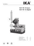
VV Micro
Betriebsanleitung
Instruction manual
Mode d’Emploi
IDI
IEI
IFi
DEUTSCH
Seite
3 - 17
ENGLISH
page
18 - 31
FRANCAISE
page
32 - 47
2
D
Wir danken Ihnen für den Kauf dieses Gerätes. Sie haben ein Produkt erworben, das von
der Firma Heidolph Instruments nach DIN EN ISO 61010 gefertigt und geprüft wurde. Mit
diesem Gerät werden Sie Ihre Arbeit einwandfrei und problemlos durchführen können.
INHALT
INHALT................................................................................................................................3
LIEFERUMFANG UND ZUBEHÖR .....................................................................................4
ALLGEMEINE HINWEISE...................................................................................................4
SICHERHEITSHINWEISE ...................................................................................................5
AUFBAU..............................................................................................................................6
1. ANTRIEB ................................................................................................................7
2. DAMPFDURCHFÜHRUNGSROHR UND VERDAMPFUNGSKOLBEN ......................................7
3. KÜHLER ................................................................................................................7
4. EINLEITUNGSROHR .................................................................................................8
5. AUFFANGKOLBEN ...................................................................................................8
6. EINSTELLUNG FÜR ABDESTILLATION .........................................................................8
7. EINSTELLUNG RÜCKFLUß-DESTILLATION ...................................................................8
8. KÜHLWASSER- UND VAKUUMANSCHLÜSSE.................................................................9
9. TEILELISTE GLASSATZ V MICRO ...............................................................................9
BEDIENUNG UND BETRIEB..............................................................................................9
HINWEISE ZU DESTILLATIONSEINSTELLUNGEN........................................................11
10. DREHZAHL DES VERDAMPFUNGSKOLBENS ...............................................................11
11. TEMPERATURDIFFERENZ ZWISCHEN HEIZBAD UND DAMPFTEMPERATUR .....................11
12. TEMPERATURDIFFERENZ ZWISCHEN DAMPFTEMPERATUR UND KÜHLMEDIUM ...............11
13. LÖSUNGSMITTELDATEN .........................................................................................11
REINIGUNG UND WARTUNG ..........................................................................................14
ABBAU, TRANSPORT UND LAGERUNG .......................................................................14
ENTSORGUNG .................................................................................................................14
STÖRUNGEN UND DEREN BESEITIGUNG ....................................................................15
TECHNISCHE DATEN ......................................................................................................15
GARANTIE, HAFTUNG UND URHEBERRECHTE ..........................................................16
FRAGEN / REPARATUREN .............................................................................................16
CE-KONFORMITÄTSERKLÄRUNG .................................................................................17
Wichtiger Hinweis
Hinweis zur Anschlussleitung / Netzanschluss
Achtung, unbedingt beachten
Achtung, Brand- oder Explosionsgefahr
Achtung: Verbrennungsgefahr, heisse Oberfläche
Hinweis zur Reparatur / Wartung
3
D
LIEFERUMFANG UND ZUBEHÖR
Bezeichnung
2
3
1
1
1
Bestellnummer
Bestellnummer
230/240V 50/60Hz
115V 50/60Hz
511-10400-00
511-10400-07
511-10300-00
511-10300-02
513-10000-00
513-10000-00
1
1
1
1
1
1
1
23-09-03-01-01
22-03-02-01-03
515-01000-00
24-03-07-01-02
11-008-010-10
14-007-003-81
01-005-001-58
Menge
Heizbad VV-Micro
Antrieb VV-Micro
Glassatz V-Micro
Lose Teile:
9
Verschraubung bearb.
10
Spannfeder
11/12 Dichtung kpl. 16 PTFE VV-micro
7
Haltestange
15
Klemme kpl.
Geräteanschlußleitung
Betriebsanleitung
23-09-03-01-01
22-03-02-01-03
515-01000-00
24-03-07-01-02
11-008-010-10
14-007-003-89
01-005-001-58
ALLGEMEINE HINWEISE
Bitte packen Sie das Gerät sorgfältig aus.
Achten Sie auf mögliche Beschädigungen und melden Sie Schäden oder
fehlende Teile unverzüglich dem Lieferanten.
Lesen Sie die Betriebsanleitung bitte gründlich und aufmerksam und sorgen
Sie dafür, dass jeder Betreiber des Gerätes vor Inbetriebnahme die
Betriebsanleitung sorgfältig gelesen hat.
Bitte bewahren Sie die Betriebsanleitung an einem für jedermann
zugänglichen Ort auf.
Die Geräte sind standardmässig mit einem EURO- Stecker (DIN 49441 CEE
7/VII 10/ 16 A 250 V) versehen.
Für Nordamerika mit einem US.NORM Stecker (NEMA Pub.No.WDI.1961
ASA C 73.1 . 1961 Seite 8 15A 125V).
Falls Sie das Gerät in einem Land mit anderem Stecker-System betreiben
möchten, müssen Sie einen zugelassenen Adapter verwenden oder der
mitgelieferte Stecker muss durch einen Fachmann ausgewechselt und durch
einen für dieses Netz passenden und zugelassenen Stecker ersetzt werden.
Bei Lieferung ist das Gerät geerdet. Beim Auswechseln des Originalsteckers
achten Sie bitte unbedingt darauf, dass der Schutzleiter am neuen Stecker
angeschlossen wird!
4
D
SICHERHEITSHINWEISE
Bitte beachten Sie alle im Labor geltenden Sicherheits- und
Unfallverhütungsvorschriften!
Beim Betrieb von Rotationsverdampfern ist die erforderliche
Sorgfaltspflicht anzuwenden.
Während des Betriebes Augenschutz und geeignete Arbeitskleidung
tragen.
Äusserste Vorsicht beim Umgang mit leicht entzündlichen Medien.
Beachten Sie die Sicherheitsdatenblätter.
Vorsicht bei der Anwendung in der Nähe von leicht entzündlichen und
explosiven Stoffen. Die Motoren arbeiten zwar funkenfrei, das Gerät ist
jedoch nicht explosionsgeschützt.
Bitte achten Sie vor der Verbindung des Gerätes mit dem Stromnetz
darauf, dass die Netzspannung mit den Angaben auf dem Typenschild
übereinstimmt.
Bitte schliessen Sie das Gerät nur an eine geerdete Netzsteckdose an.
Schalten Sie den Netzschalter aus, wenn das Gerät nicht in Betrieb ist,
bzw. bevor es vom Netz genommen wird.
Achtung! Verbrennungsgefahr beim Betrieb des Heizbades über 60°C.
Heissen Metallrand des Badbehälters, Verdampferkolben und
Badflüssigkeit nicht berühren. Zum Wechsel des Verdampferkolbens
geeigneten Wärmeschutzhandschuh benutzen.
Heizbad nie ohne Flüssigkeit betreiben.
Reparaturen dürfen nur von einem von Heidolph Instruments
autorisierten Fachmann ausgeführt werden.
Bitte achten Sie auf sicheren Stand des Gerätes!
Den Rotationsverdampfer auf einer glatten, horizontalen Tischfläche
aufstellen. Darauf achten, dass im Bewegungsraum des Verdampfers
genügend Sicherheitsabstand gewährleistet ist!
Darauf achten, dass niemals Überdruck im System entstehen kann.
Explosionsgefahr. Beim Arbeiten ohne Vakuum aus Sicherheitsgründen
Belüftungshahn öffnen, um unzulässigen Überdruck zu vermeiden
5
D
AUFBAU
Vor dem Aufbau beachten Sie bitte die allgemeinen Informationen und
Sicherheitshinweise!
6
D
1.
Antrieb
Antrieb mit Klemmring (4) an der Haltestange (1) befestigen. Die schwarze
Überwurfmutter (9) muß nach innen in Richtung des Heizbades (2) weisen und das
elektrische Anschlußkabel (6) muß nach unten führen.
Den Klemmring (4) einschließlich der Antriebseinheit durch Festziehen des
Sterngriffes (5) an der Haltestange (1) befestigen.
Anschlußkabel mit Stecker (6) in entsprechende Buchse auf der Rückseite des
Heizbadgehäuses (2) stecken.
Die Haltestange (7) für den Kühler in die Gewindebohrung der
Verbindungsmuffe (8) schrauben.
2.
Dampfdurchführungsrohr und Verdampfungskolben
Die schwarze Uberwurfmutter (9), den Federspannring (10), die Dichtung PTFE (11)
und den Silikonring (12) vom Antrieb entfernen.
Das Dampfdurchführungsrohr (A) mit dem schwarzen Sicherungsring (B) »von der
Seite mit dem roten Sicherungsknopf (14)« bis zum Anschlag in die Antriebseinheit
einstecken. Der seitliche Auslaß des Dampfdurchführungsrohres muß parallel zur
Haltestange (7) sein.
Den Silikonring (12) auf das Dampfdurchführungsrohr (A) schieben (von der Badseite
aus) - mit der gewölbten Fläche zuerst. Danach die Dichtung PTFE (11) soweit wie
möglich (mit der Dichtlippe voraus) auf das Dampfdurchführungsrohr (A) setzen.
Zuerst die Überwurfmutter (9), dann den Federspannring (10) auf den Hals des
Verdampfungskolbens (C,D,E) oder des
Übergangsstückes (F) setzen.
13
Den Flansch des Kolbens über das Dampfdurchführungsrohr (A) in den Antrieb und gegen
die Dichtung setzen. Den Kolben soweit wie
möglich drücken und Überwurfmutter (9) mäßig
festziehen.
Zur ausreichenden Befestigung der Überwurfmutter
und des Kolbens den Halteknopf (13) drücken und
damit das Getriebe blockieren (siehe Abbildung).
3.
Kühler
Bei aufrechter Position des Kühlers läßt sich der Glassatz
leichter montieren. Dazu sollte die Haltestange (7) senkrecht
14
stehen. Andernfalls den roten Sicherungsknopf (14) lockern
und Halteknopf (13) herausziehen, so daß die
Verbindungsmuffe (8) um 180° geschwenkt werden kann.
Der Halteknopf (13) schnappt dann ein und die Haltestange
steht aufrecht. Roten Sicherungsknopf (14) wieder
festziehen.
Den Stumpfverbindungsflansch (G) auf den seitlichen
Gewindestutzen des Dampfdurchführungsrohres (A) schrauben
und den Dichtungsring (G1) einsetzen.
Klemme (15) auf die Haltestange (7) stecken und den Kühler (H)
mittels der Klemme an der Haltestange befestigen.
Sicherstellen, daß sich die Wasser- und Vakuumanschlüsse des
Kühlers am oberen Ende befinden. Mittels Stumpfverbindungsflansch (G) die Kühlereinheit
7
D
(H) auf das Dampfdurchführungsrohr (A) schrauben. Roter Sicherungsknopf (14) muß
festgezogen sein, damit Kühler und Haltestange abgesichert sind.
4.
Einleitungsrohr
Die Lochschraubkappe (l) und die Dichtung (l1) auf das Einleitungsrohr (K) setzen.
Danach das Einleitungsrohr in das offene Ende des Dampfdurchführungsrohrs (A)
einsetzen und die Lochschraubkappe (l) festziehen.
Das Ventil des Einleitungsrohres ist aus PTFE und wird fettfrei betrieben.
5.
Auffangkolben
Stumpfverbindungsflansch (G) auf das offene Ende des Kühlers (H) schrauben,
Dichtungsring (G1) und den Auffangkolben (L,M,N) oder den Vakuumverschluß (0) auf das
andere Ende der Einheit schrauben (jeweils entsprechend der Destillationsmethode).
6.
Einstellung für Abdestillation
(ausgehend von Position RückflußDestillation)
Auffangkolben schaut nach unten
(siehe Abbildung). Den roten
Sicherungsknopf (14) lockern,
Halteknopf (13) herausziehen und den
Kühler um 180° schwenken
(einschließlich Kolben und
Haltestange), bis der Halteknopf (13)
in der zweiten Position einklinkt.
Danach roten Sicherungsknopf (14) wieder
festziehen.
7.
Einstellung Rückfluß-Destillation
(Ausgehend von Position Abdestillation)
Bei der Rückfluß-Destillationsmethode steht der
Kühler in aufrechter Position (siehe Abbildung) und
statt des Auffangkolbens (L) wird ein
Vakuumverschluß (0) verwendet. Zur
Positionsänderung wiederum den Sicherungsknopf
(14) lockern, Halteknopf (13) herausziehen und den
Kühler einschließlich Kolben und Haltestange um
180° schwenken, bis Halteknopf (13) einklinkt.
Danach Sicherungsknopf (14) festziehen.
8
D
8.
Kühlwasser- und Vakuumanschlüsse
Kühlwasseranschlüsse (H2) und Vakuumanschluß (H1) seitlich am Kühler anschließen
und durch Schlauchschellen sichern (nicht im Lieferumfang enthalten).
9.
Teileliste Glassatz V Micro
Bestell-Nr.:
514-40000-00
514-72100-00
514-71100-00
514-70100-00
514-33000-00
514-45000-00
514-20000-00
514-46000-00
514-50000-00
514-82100-00
514-81100-00
514-80100-00
514-34000-00
Pos.
A+B
C
D
E
F
G + G1
H
I + I1
K + K1
L
M
N
O
Bestellbezeichnung
Dampfdurchführungsrohr mit Auflagering
Verdampferkolben 250 ml
Verdampferkolben 100 ml
Verdampferkolben 50 ml
Übergangsstück NS 14,5
Stumpfverbindungsflansch mit Dichtung
Kühler K-micro
Lochschraubkappe mit Dichtung
Einleitungsrohr mit Ventil
Auffangkolben 250 ml
Auffangkolben 100 ml
Auffangkolben 50 ml
Vakuumverschluß
Stück
1
1
1
1
1
1
1
1
1
1
1
1
1
BEDIENUNG UND BETRIEB
Achtung:
Vor Inbetriebnahme des Gerätes unbedingt die Sicherheitshinweise
und allgemeinen Informationen lesen!
Vor der Verbindung des Gerätes mit dem Netz darauf achten, daß
Gerätespannung und Netzspannung übereinstimmen.
Dementsprechend auch landesübliche Stecker verwenden. Siehe
hierzu auch Hinweis unter allgemeine Hinweise Seite 4
o
Alle beteiligten Komponenten und deren Funktion überprüfen!
o
Auf Dichtheit aller Anschlüsse achten.
o
Wasser ins Heizbad füllen. Die Minimum-/Maximumangaben beziehen sich auf den
Flüssigkeitspegel bei eingetauchtem Verdampfungskolben
16
o
Wasser oder alternative Flüssigkeit
durch den Kühler laufen lassen.
o
Lösungsmittel in den
Verdampfungskolben geben.
o
Verdampfungskolben mit Feststellknopf (16) und
Sterngriff (5) so im Heizbad positionieren, daß zur
Badbehälterwand ein Sicherheitsabstand von mindestens
10 mm eingehalten wird. (siehe Abbildung). Vorher nicht
9
D
den Schalter (17) für die Kolbenrotation einschalten.
o
Bei Verwendung von entionisiertem oder destilliertem Wasser:
Wasser mit 0,2% Borax (Na2 B4 O7*10 H2O) versetzen
o
Die Eintauchtiefe des Verdampferkolbens in der Badflüssigkeit wird durch die
Höhenverschiebung des gesamten Antriebes eingestellt. Dazu Antriebseinheit
(3) festhalten, Sterngriff (5) lösen, Antrieb entsprechend verschieben und
Sterngriff wieder festziehen.
o
Die Badheizung wird mit dem Schalter (18) eingeschaltet (Kontrollampe
leuchtet). Mit dem Drehknopf (20) wird die Badtemperatur gewählt.
Achtung: Verbrennungsgefahr beim Betrieb des Heizbades!
Zur Sicherheit wird die Heizbadtemperatur durch einen zusätzlichen
Maximaltemperaturbegrenzer überwacht. Fällt der Temperaturregler aus,
schaltet der Maximaltemperaturbegrenzer die Heizung bleibend ab.
o
Der Maximaltemperaturbegrenzer befindet sich an der Unterseite des
Heizbades. Hat er abgeschaltet, muß das Gerät geöffnet werden, um den roten,
herausgesprungenen Knopf am Boden des Heizbades wieder einzurücken und
den Maximaltemperaturbegrenzer damit nach ausreichender Abkühlung wieder
zurückzustellen.
o
Spricht der Maximaltemperaturbegrenzer an,
ist grundsätzlich eine Überprüfung des
Heizbades durch einen von Heidolph
autorisierten Servicetechniker notwendig.
o
Die Kolbenrotation wird mit dem Schalter (17)
eingeschaltet (Kontrollampe leuchtet), wobei
Drehknopf (19) auf 0 (Linksanschlag) stehen
muß. Mit Drehknopf (19) anschließend die
gewünschte Drehzahl einstellen.
o
Wenn das System unter Vakuum steht, kann Lösungsmittel in den
Verdampferkolben nachdosiert werden. Hierzu das Einleitungsrohr (K) mit einem
Schlauchstück (di ~ 6 mm) verbinden. Das Schlauchende in den
Lösungsmittelbehälter geben. Mit dem Ventil (K1) kann die gewünschte Menge
dosiert werden.
o
Der VV Micro kann während des Betriebes von Rückflußdestillation auf
Abdestillation umgestellt werden. Achtung: Vor Destillationsbeginn einen
ausreichend großen Auffangkolben einsetzen. Zur Umstellung
Sicherungsknopf (14) lösen, Halteknopf (13) herausziehen und den Kühler um
180° schwenken, bis Halteknopf (13) einrastet. Sicherungsknopf (14) wieder
festziehen.
o
Nach Beendigung der Destillation den Verdampferkolben durch Lösen des
Sterngriffes (5) und Verschieben der Antriebseinheit aus dem Bad heben.
10
20
18
17
19
D
o
Bitte vor einem ersten Laboreinsatz eine allgemeine Funktionsprüfung von
Schaltern, Drehknöpfen, Antrieb usw. durchführen.
HINWEISE ZU DESTILLATIONSEINSTELLUNGEN
Bei der Verwendung eines Rotationsverdampfers zur thermischen Stofftrennung sollten
verschiedene Punkte beachtet werden, um bestmögliche Destillationsergebnisse zu
erzielen. Für eine optimale Einstellung müssen folgende Parameter berücksichtigt werden:
10. Drehzahl des Verdampfungskolbens
Durch Erhöhung der Drehzahl lässt sich die Destillationsgeschwindigkeit steigern. Dies
trägt durch die verkürzte Destillationszeit zur thermischen Schonung des
Destillationsgutes bei.
11. Temperaturdifferenz zwischen Heizbad und Dampftemperatur
Diese Temperaturdifferenz sollte bei mindestens 20 K liegen, um eine ausreichend hohe
Destillationsgeschwindigkeit zu erreichen. Wenn es die thermische Stabilität des
Destillationsgutes erlaubt, kann die Temperaturdifferenz auch größer gewählt werden.
Faustregel: die Verdoppelung der Temperaturdifferenz führt zu einer
Verdoppelung der Destillationsgeschwindigkeit.
12. Temperaturdifferenz zwischen Dampftemperatur und Kühlmedium
Diese Temperaturdifferenz sollte ebenfalls bei mindestens 20 K liegen, um eine
ausreichende Kondensation zu gewährleisten. Bei zu niedriger Temperaturdifferenz wird
die Effektivität der Lösungsmittelrückgewinnung verschlechtert. Insbesondere bei
Substanzen mit hoher Verdampfungswärme sollte eher eine größere Temperaturdifferenz
gewählt werden.
13. Lösungsmitteldaten
Beispiele für die Anwendung der Tabelle und des Nomogramms:
Die Tabelle gibt die für die Destillation wichtigsten Stoffdaten wieder, das Nomogramm
gibt die Beziehung zwischen Druck und Siedetemperatur einiger Lösungsmittel wieder.
Hierfür wurde entsprechend der Gleichung von Clausius-Clapeyron 1/T gegen log p
aufgetragen.
13.1. bei Siedetemperatur 40°C
Am Vakuumcontroller wird der in der Spalte „Vakuum für Sdp. bei 40°C angegebene Wert
als Sollwert Set Vac eingestellt.
11
D
13.2. bei Siedetemperaturen ungleich 40°C
1. Auf der Temperaturachse des Nomogramms wird der gewünschte Siedepunkt
markiert.
2. Durch ziehen einer Linie nach rechts wird der Schnittpunkt mit der LösungsmittelGeraden ermittelt.
3. Von diesem Schnittpunkt senkrecht nach unten kann das notwendige Vakuum
abgelesen werden.
13.3. bei Lösungsmitteln die nicht aufgeführt sind
-
Für die Ermittlung des richtigen Vakuums können folgende Punkte eine Hilfestellung
sein:
1. Die Steigung der Geraden wird durch die Verdampfungsenthalpie bestimmt. Sie ist für
chemisch verwandte Substanzen mit naheliegendem Siedepunkt ähnlich. Die
eingezeichneten Geraden können somit als Orientierung für Substanzen mit leicht
abweichendem Siedepunkt dienen.
2. Mit einer Wasserstrahl- oder Membranpumpe lässt sich eine Siedepunkterniedrigung
von ca. 100 °C erreichen.
3. Faustregel: Die Reduzierung des Druckes um die Hälfte erniedrigt den Siedepunkt um
etwa 15 °C.
12
D
Lösungsmittel
Aceton
Acetonitril
Benzol
n-Butanol (Butylalkohol)
tert.-Butanol (tert.-Butylalkohol)
2-Butanon (Methylethylketon)
tert.-Butylmethylether
Chlorbenzol
Cyclohexan
1,2-Dichlorethan
1,2-Dichlorethylen (cis)
1,2-Dichlorethylen (trans)
Dichlormethan (Methylenchlorid)
Diethylether
Diisopropylether
Dimethylformamid
1,4-Dioxan
Ethanol
Ethylacetat
Heptan
Hexan
Methanol
3-Methyl-1-Butanol (Isoamylalkohol)
Pentachlorethan
Pentan
n-Pentanol (Amylalkohol)
1-Propanol (n-Propylalkohol)
2-Propanol (Isopropylalkohol)
1,1,2,2-Tetrachlorethan
Tetrachlorethylen
Tetrachlormethan (Carbontetrachlorid)
Tetrahydrofuran
Toluol
1,1,1-Trichlorethan
Trichlorethylen
Trichlormethan (Chloroform)
Wasser
Xylol (Isomeren-Gemisch)
Summenformel
MW
[g/mol]
Sdp.
[°C]
ΔHvap
[J/g]
C3H6O
C2H3N
C6H6
C4H10O
C4H10O
C4H8O
C5H12O
C6H5CI
C6H12
C2H4CI2
C2H2CI2
C2H2CI2
CH2CI2
C4H10O
C6H14O
C3H7NO
C4H8O2
C2H6O
C4H8O2
C7H16
C6H14
CH4O
C5H12O
C2HCI5
C5H12
C5H12O
C3H8O
C3H8O
C2H2CI4
C2CI4
CCI4
C4H8O
C7H8
C2H3CI3
C2HCI3
CHCI3
H2O
C8H10
58,08
41,05
78,11
74,12
74,12
72,11
88,15
112,60
84,16
98,96
96,94
96,94
84,93
74,12
102,20
73,09
88,11
46,07
88,11
85,09
86,18
32,04
88,15
202,30
72,15
88,15
60,10
60,10
167,90
165,80
153,80
72,11
92,14
133,40
131,40
119,40
18,02
106,20
56,5
81,8
80,1
117,5
82,9
79,6
55,0
132,2
80,7
82,4
59,0
47,8
40,7
34,6
67,5
153,0
101,1
78,4
77,1
98,4
68,7
64,7
130,6
160,5
36,1
137,8
97,8
82,5
145,9
120,8
76,7
66,0
110,6
74,1
86,7
61,3
100,0
137-143
550
833
549
619
588
473
13
375
389
336
320
313
373
392
318
406
879
394
439
370
1225
593
203
382
593
787
701
247
233
225
425
251
265
263
2259
390
Vacuum für
Sdp bei 40°C
[mbar]
556
230
236
25
130
243
36
235
210
479
751
atm.
atm.
375
11
107
175
240
120
335
337
14
13
atm.
11
67
137
35
53
271
357
77
300
183
474
72
25
D
REINIGUNG UND WARTUNG
Zur Reinigung Gehäuse und Oberfläche des Gerätes mit einem feuchten Tuch (milde
Seifenlauge) abwischen.
HINWEIS: Auf keinen Fall zur Reinigung Chlorbleiche, auf Chlorbasis
aufbauende Putzmittel, Scheuermittel, Ammoniak, Putzwolle oder
Reinigungsmittel mit metallischen Bestandteilen verwenden. Die
Oberfläche des Gerätes würde dadurch Schaden erleiden.
Dampfdurchführung (A+B Seite 6) und Dichtung PTFE (11/12 Seite 6)
bedürfen einer regelmäßigen Wartung. Dazu Dampfdurchführung (A+B)
und Dichtung PTFE (11/12) ausbauen, reinigen und überprüfen
(Dichtlippe). Die Dichtung PTFE ist gegebenenfalls auszutauschen.
Montage von Dampfdurchführung und Dichtung PTFE siehe Kapitel 2.
Das Gerät ist wartungsfrei. Eine eventuell notwendige Reparatur ist unbedingt von einem
durch Heidolph autorisierten Fachmann auszuführen. Wenden Sie sich hierzu an Ihren
HEIDOLPH-Händler bzw. an die HEIDOLPH-Vertretung.
ABBAU, TRANSPORT UND LAGERUNG
Abbau
o
o
Gerät abschalten und Netzstecker aus der Steckdose ziehen (abkühlen lassen).
Gerätschaften um den Verdampfer herum entfernen, damit das Gerät problemlos
abgebaut werden kann. Den Glassatz entfernen und gesamtes Gerät und
Geräteteile in umgekehrter Reihenfolge wie beim Aufbau demontieren.
Transport und Lagerung
1. Das Gerät und seine Teile in der Originalverpackung lagern oder in einem anderen
geeigneten Behälter, um Schäden während eines Transportes zu vermeiden. Die
Verpackung mit Klebestreifen verschließen.
2. Das Gerät ist an einem trockenen Ort aufzubewahren.
Vorsicht: Beim Transport des Gerätes ist darauf zu achten, dass Stöße und
Erschütterungen vermieden werden.
ENTSORGUNG
Wir bitten Sie, darauf zu achten, Altgeräte bzw. defekte Geräteteile bei einer Sammelstelle
fachgerecht entsorgen zu lassen. Trennen Sie bitte auch das Altmaterial in Metall, Glas,
Kunststoff usw.
Entsorgen Sie bitte auch das Verpackungsmaterial umweltgerecht (Materialtrennung).
14
D
STÖRUNGEN UND DEREN BESEITIGUNG
Keine Heizfunktion:
o
Netzleitung überprüfen
o
Kapillarrohrregler defekt
o
Schalter ein/aus defekt
o
Rohrheizkörper defekt
Antrieb dreht nicht:
o
Steckdose führt keinen Strom
o
Netzleitung und Verbindungskabel zum Basisgerät überprüfen
o
Einstellpotentiometer defekt
o
Schalter ein/aus defekt
o
zu niedrige Drehzahl eingestellt
o
schwarze Überwurfmutter wurde zu stark angezogen
o
Motor defekt
o
Motorkondensator defekt
Kein ausreichendes Vakuum:
o
Dichtungen und Anschluß (insges. 6 Stellen) überprüfen
o
evtl. verschlissene Dichtungen erneuern
o
auf korrekten Sitz der Dichtung achten (Dichtlippe ins Gerät, vergl. Zeichnung
Seite 6)
TECHNISCHE DATEN
Modell
VV-Micro
Antrieb
Kondensatormotor mit Drehzahlsteuerung
Drehzahlbereich (1/min)
80 - 200
Drehzahlkontrolle
Skala
Heizleistung (W)
500
Temperaturbereich Wasserbad (°C) 30 - 100
Regelgenauigkeit Wasserbad (°C)
±5
Anzeige Badtemperatur
Skala
Material Heizbad
Chromstahl
Durchmesser Heizbad (mm)
139
Anschlußspannung
230 V / 50 Hz o. 115V/60Hz (auch andere)
Anschlußleistung (W)
530
Gewicht ohne Glassatz (kg)
6,9
Abmessungen** (B xTxH) (mm)
167x235x350
Länge Anschlußkabel (m)
2
Schutzart
IP 21
Zulässige Umgebungsbedingungen 0 - 40° C bei 80 % Luftfeuchtigkeit
Verdampfungsleistung (ml H2O / h) ca. 250
Kühlfläche (cm2)
270
Bestellnummer
511.12000.00
**Antrieb in oberster Position, ohne Glassatz
15
D
GARANTIE, HAFTUNG UND URHEBERRECHTE
Garantie
Die Firma Heidolph Instruments gewährt Ihnen auf die hier beschriebenen Produkte
(ausgenommen Glas- und Verschleißteile) eine Garantie von drei Jahren, wenn Sie sich
mit beiliegender Garantiekarte oder per Internet registrieren (www.heidolph.com). Die
Garantie beginnt mit der Registrierung. Ohne Registrierung hat die Seriennummer des
Gerätes Gültigkeit.
Diese Garantie umfasst Material- und Herstellungsfehler. Transportschäden sind
ausgeschlossen.
Im Falle eines Garantieanspruchs benachrichtigen Sie bitte Heidolph Instruments
(Tel.: (+49) 9122 - 9920-69) oder Ihren Heidolph Instruments Händler. Wenn es sich um
einen Material- oder Herstellungsfehler handelt, wird Ihnen im Rahmen der Garantie das
Gerät kostenfrei repariert oder ersetzt.
Für Schäden durch unsachgemäße Behandlung kann von der Firma Heidolph Instruments
keine Garantie übernommen werden.
Eine Änderung dieser Garantieerklärung bedarf in jedem Fall einer schriftlichen
Bestätigung durch die Firma Heidolph Instruments.
Haftungsausschluss
Für Schäden durch unsachgemäße Behandlung und Verwendung kann von der Firma
Heidolph Instruments keine Haftung übernommen werden. Folgeschäden sind von der
Haftung ausgeschlossen.
Urheberrecht
Das Urheberrecht (Copyright) für alle Bilder und Texte in dieser Betriebsanleitung liegt bei
Heidolph Instruments.
FRAGEN / REPARATUREN
Haben Sie nach dem Lesen der Betriebsanleitung noch Fragen zu Installation, Betrieb
oder Wartung, wenden Sie sich bitte an die im Folgenden genannte Adresse.
Bei Reparaturen wenden Sie sich bitte vorab telefonisch an Heidolph Instruments direkt
(Tel.: (+49) 9122 - 9920-69) oder an Ihren autorisierten Heidolph Instruments Händler.
Hinweis
Bitte senden Sie Geräte ausschließlich nach vorheriger Rücksprache an diese
Anschrift:
Heidolph Instruments GmbH & Co. KG
Vertrieb Labortechnik
Walpersdorfer Str. 12
D-91126 Schwabach / Deutschland
Tel.: +49 – 9122 - 9920-69
Fax: +49 – 9122 - 9920-65
E-Mail: [email protected]
16
D
Sicherheitshinweis
Bitte sorgen Sie bei der Anlieferung von Reparaturgeräten, die mit
gefährlichen Arbeitsstoffen in Berührung gekommen sind für:
Möglichst genaue Stoffangaben des entsprechenden Mediums
Schutzmassnahmen zum sicheren Umgang für unser Annahme- und
Wartungspersonal.
Kennzeichnung der Verpackung gemäss der Gefahrenstoffverordng
CE-KONFORMITÄTSERKLÄRUNG
Wir erklären, dass dieses Produkt mit folgenden Normen und normativen Dokumenten
übereinstimmt:
EMV-Richtlinie:
EN 61326: 1997 + A1:1998 + A2:2001+ A3 2003
EN 61000-3-2: 2000
EN 61000-3-3: 1995 + 1997 + A1:2001
EN 61326: 1997 + A1:1998 + A2: 2001+ A3 2003
EN 61000-4-3:2002 +A1:2002
EN 61000-4-5:1995 +A1:2001
EN 61000-4-6:1996 +A1:2001
EN 61000-4-8: 1993
EN 61000-4-11:1994 + A1:2001
Niederspannungs-Richtlinie:
EN 61010-1 + EN 61010-2-010
17
E
Thank you for purchasing a Heidolph Instruments product. This item has been designed,
made and inspected in compliance with DIN EN ISO 61010 for long performance and
continuous operation.
SUMMARY
SUMMARY ........................................................................................................................18
STANDARD ITEM PLUS OPTIONS .................................................................................19
GENERAL .........................................................................................................................19
SAFETY INFORMATION ..................................................................................................20
SET-UP..............................................................................................................................21
1. DRIVE UNIT ..........................................................................................................22
2. VAPOR SUPPORT TUBE AND EVAPORATION FLASK .....................................................22
3. CONDENSER ........................................................................................................22
4. INLET TUBE ..........................................................................................................23
5. COLLECTION FLASK ..............................................................................................23
6. SETTING UP FOR NORMAL DISTILLATION ..................................................................23
7. SETTING UP FOR REFLUX DISTILLATION ...................................................................23
8. COOLING WATER AND VACUUM CONNECTIONS .........................................................23
9. PART LIST GLASS SET V-MICRO .............................................................................24
CONTROLS AND OPERATION........................................................................................24
INFORMATION ABOUT DISTILLATION SETTINGS .......................................................25
10. ROTARY SPEED OF EVAPORATOR FLASK ..................................................................26
11. TEMPERATURE DIFFERENCE BETWEEN HOT BATH AND VAPOR ....................................26
12. TEMPERATURE DIFFERENCE BETWEEN VAPOR TEMPERATURE AND COOLANT ...............26
13. SOLVENT DATA .....................................................................................................26
CLEANING AND MAINTENANCE ....................................................................................28
DISASSEMBLE, FORWARD & STORE ...........................................................................28
DISPOSAL ........................................................................................................................28
TROUBLESHOOTING ......................................................................................................29
SPECIFICATIONS.............................................................................................................29
WARRANTY, LIABILITY & COPYRIGHT .........................................................................30
FAQ / REPAIR WORK ......................................................................................................30
CE-DECLARATION OF CONFORMITY............................................................................31
Important information
Advice about power cord / mains supply
Caution: mandatory action
Caution: fire- and explosion hazard
Caution: hazard of burns, hot surface
Advice about maintenance / repair
18
E
STANDARD ITEM PLUS OPTIONS
Item
Description
1
1
1
Order number
Order number
230/240V 50/60Hz
115V 50/60Hz
511-10400-00
511-10400-07
511-10300-00
511-10300-02
513-10000-00
513-10000-00
1
1
1
1
1
1
1
23-09-03-01-01
22-03-02-01-03
515-01000-00
24-03-07-01-02
11-008-010-10
14-007-003-81
01-005-001-58
Qty
2
3
Heating bath VV-Micro
Drive VV-Micro
Glass set V-Micro
loose parts:
9
Screw collar
10
Spring tension ring
11/12 PTFE seal 16 VV-micro
7
Support rod 7mm
15
Clamp complete
Power cord
Instruction manual
23-09-03-01-01
22-03-02-01-03
515-01000-00
24-03-07-01-02
11-008-010-10
14-007-003-89
01-005-001-58
GENERAL
Unpack your item carefully.
Inspect for damage and report such damage or missing parts to your supplier
immediately.
Read your Instruction Manual carefully. Take the time to read the manual
which will save time while working with your product. Make sure that every
user has read and understands the Instruction Manual.
Please store the Instruction Manual in a place easily accessible to every
user.
IF ALL ELSE FAILS, READ THESE INSTRUCTIONS !
A so-called EURO-plug (DIN 49441 CEE 7/VII 10/ 16 A 250 V) is standard on
all of the products.
For the Continental US they feature a US-standard plug (NEMA
Pub.No.WDI.1961 ASA C 73.1 . 1961 page 8 15A 125V).
For using the item in a country with deviating outlet / plug systems, we
recommend to use approved adapters or to have an electrician replace the
standard plug with one mating your local system.
As shipped, the item features a protective ground wire. When replacing the
original plug, make sure to reconnect this protective ground wire in the new
plug !
19
E
SAFETY INFORMATION
Please comply with all safety and accident prevention regulations as in
force for laboratory work !
Use extra care while working with rotary evaporators.
Use eye protection and adequate clothing.
Use extra care while working with flammable substances; refer to safety
data sheets.
Use extra care while working close to flammable and explosive
substances. Motors are of non-sparking type, the item itself is not
explosion-protected.
Before connecting your item with the local power supply, make sure the
item has been designed for your local voltage; refer to data plate on
item.
Connect your item with a grounded outlet only.
Turn power switch to OFF when item is not in use, or before
disconnecting from mains.
Caution ! Hazard of burns when running the hot bath at temperatures
exceeding 60°C. Avoid touching hot edge of bowl, evaporator flask and
fluid in bowl. Use gloves when replacing evaporator flask.
Never run hot bath dry.
Repair work is limited to skilled personnel so authorized by Heidolph.
Your item needs a solid stand.
Locate the rotary evaporator on a smooth, horizontal table. Make sure not to
obstruct area around evaporator.
Avoid overpressure in the system. Explosion hazard. For reasons of
safety open aerating valve, when working at ambient pressure, in order
to avoid excessive overpressure.
20
E
SET-UP
Please read the sections „General Information" and „Safety Instructions" before
you assemble the appliance.
21
E
1.
Drive unit
Mount the drive on the support rod (1) with the clamping ring (4). The black screw collar
(9) must face inwards towards the heating bath and the electric power cable (6) must point
down.
Secure the clamping ring (4) with the drive unit by tightening the star grip (5) on the
support rod (1).
Insert the power cable with plug (6) in the correct socket on the rear of the heating bath
housing (2).
Screw the support rod (7) for the condenser in the threaded hole of the coupling (8).
2.
Vapor support tube and evaporation flask
Remove the black screw collar (9), the spring tension ring (10), the PTFE seal (11) and the
silicon ring (12) from the drive.
From the side with the red locking knob (14), insert the vapor tube (A) with the black
support ring (B) in the drive unit as far as the stop. Make sure the side outlet of the vapor
tube is parallel to the support rod (7).
From the bath side, slide the silicon ring (12) - curved
face first - on the vapor tube (A). Then slide the
13
PTFE seal (11) - sealing lip first - on the vapor
support tube as far as it will go.
Place first the screw collar (9) and then the spring
tension ring (10) on the neck of the evaporation flask
(C, D, E) or transition piece (F).
Slide the flange over the vapor support tube (A) and
into the drive up against the seal. Push the flask as
far as it will go and half tighten the screw collar.
To give the screw collar and flask sufficient hold,
press the fastening knob (13) to lock the gear.
3.
Condenser
14
The glass set is easier to mount when the condenser is in
upright position.
The support rod (7) should be vertical. If not, loosen the red
locking knob (14) and pull out the fastening knob (13) so that
the coupling (8) can be swivelled 180°. The fastening knob (13)
will then latch home again and the support rod will be in upright
position. Re-tighten the red locking knob (14).
Screw the butt flange (G) to the threaded socket on the side of
the vapor support tube (A) and insert the sealing ring (G1).
Place the clamp (15) on the support rod (7) and fasten the
condenser (H) to the support rod with the clamp. Make sure that
the condenser's water and vacuum connections are at the top
end. Using the butt flange (G), screw the condenser unit (H) to the vapor tube (A). The red
locking button (14) must be tight in order to provide a secure hold for the condenser and
support rod.
22
E
4.
lnlet tube
Place the screw connection cap (I) and the seal (I1) on the inlet tube (K).
Then insert the inlet tube in the open end of the vapor tube and tighten the screw
connection cap (I). Inlet valve is made of PTFE, please do not grease.
5.
Collection flask
Screw the butt flange (G) on the open end of the condenser (H) and screw the sealing
ring (G1) and the collection flask (L, M, N) or vacuum cap (0) on the other end of the
unit (according to the intended method of distillation).
6.
Setting up for normal distillation
(Starting from the position for reflux
distillation)
For normal distillation the collection
flask has to point down. Slacken the
red locking knob (14), pull out the
fastening knob (13) and swivel the
condenser (with flask and support
rod) through 180° until the fastening
knob (13) latches in the second position. Then re-tighten the red locking
knob (14).
7.
Setting up for reflux distillation
(Starting from the position for normal
distillation)
For reflux distillation the condenser has to be in
upright position and a vacuum cap (0) is used
instead of the collection flask (L). To re-position
the condenser, loosen the locking knob (14),
pull out the fastening knob (13) and swivel the
condenser with flask and support rod through
180° until the fastening knob (13) latches home.
Then tighten the locking knob (14).
8.
Cooling water and vacuum connections
Join the cooling water connections (H2) and the
vacuum connection (H1) to the side of the
condenser and secure with hose clips (not
supplied).
23
E
9.
Part list Glass set V-Micro
Order number
514-40000-00
514-72100-00
514-71100-00
514-70100-00
514-33000-00
514-45000-00
514-20000-00
514-46000-00
514-50000-00
514-82100-00
514-81100-00
514-80100-00
514-34000-00
Item
A+B
C
D
E
F
G + G1
H
I + I1
K + K1
L
M
N
O
Description
Vapor tube with Support ring
Evaporation flask 250 ml
Evaporation flask 100 ml
Evaporation flask 50 ml
Transition piece NS 14,5
Butt flange with Seal for butt flange
Cooler K-micro
Screw connection cap with Seal
Inlet tube with Valve
Collection flask 250 ml
Collection flask 100 ml
Collection flask 50 ml
Vacuum cap
Qty
1
1
1
1
1
1
1
1
1
1
1
1
1
CONTROLS AND OPERATION
Important:
It is imperative to read the section „Safety instructions" and „General
information" before you use the appliance for the first time.
Before connecting the appliance to the power supply, make sure that
your supply voltage is the same as that on the rating plate of the
appliance. Use plugs approved for your country. In this connection,
please read the note in the section „General" on page 19.
o
o
o
o
o
o
Check all components and make sure they are in working order!
Check all connections for leaks.
Add water to the heating bath. The minimum/maximum volumes of the heating
bath refer to the liquid level with the evaporating flask immersed.
Run water or an alternative liquid through the condenser.
Add solution to the evaporation flask.
o
Use the locating knob (16) and star
grip (5) to position the evaporation
flask in the heating bath with a
safety clearance of at least 10 mm
between the flask and the bath wall
(see detail view on page 14). The
flask rotation switch (17) is not to
be used before this point.
o
When using to de-ionized or distilled water:
16
Add 0,2% borax (Na2B4O7 * 10 H2O)
The depth of immersion of the evaporation flask in the bath liquid is set by vertical
adjustment of the complete drive. Holding the drive unit (3) securely, slacken the
24
E
o
star grip (5), move the drive up or down accordinqly and retighten with the star
grip.
Use switch (18) to turn on the bath heater (the pilot lamp lights up). You can
select the bath temperature with knob (20).Caution: Risk of scalding when
using the heating bath!
o
For reasons of safety, hot bath temperature is monitored by a temperature
limiter. If temperature control fails, the temperature limiter permanently
disconnects heater.
o
This temperature limiter is located on the underside of the heating bath.
Disconnect status is displayed by a red protruding button. The unit must be
opened. To reset temperature limiter just depress red button after some time for
chilling off.
The temperature limiter having dropped, is an indication to have the hot
bath inspected by a service engineer authorized by Heidolph.
o
o
o
o
o
When you are sure that the knob (19) is set to 0 (turn counterclockwise as far as
the stop), use the switch (17) to turn on the flask
17
18
19
20
rotation (the Pilot lamp lights up). Then you can
use the knob (19) to set the required speed.
You can add solvent to the evaporation flask
when the system is under vacuum. To do so,
connect the inlet tube (K) to a length of tubing
(dia 6 mm) and place the end of the tubing in the
solvent container. Use the valve (K1) to regulate
the required amount of solvent.
You can switch over the VV Micro from reflux
distillation to normal distillation while it is in
operation. Important: Fit a large enough
collection flask before beginning with the distillation. To switch over, release
the locking knob (14), pull out the fastening knob (13) and swivel the condenser
through 180° until the fastening knob (13) latches home. Re-tighten the locking
knob (14).
When the distillation is over, lift the evaporation flask out of the bath by undoing
the star grip (4 and/or 5) and moving the drive unit.
Before you use the appliance in the laboratory for the first time, please check
that its switches, knobs, drive etc. are in working order.
INFORMATION ABOUT DISTILLATION SETTINGS
Using a rotary evaporator for thermal cracking of substances some basic consideration
should be made to achieve the best results possible. Optimize settings as described
below:
25
E
10. Rotary speed of evaporation flask
Raise distillation speed by raising rotational speed. This methods cuts distillation time and
protects the substances handled.
11. Temperature difference between hot bath and vapor
This temperature difference should at least be 20 K to reach adequate distillation speed. If
acceptable by thermal stability of the substances handled, you even may raise the
temperature difference.
Rule of thumb: double temperature to double distillation speed.
12. Temperature difference between vapor temperature and coolant
This temperature difference should be no less than 20 K to guarantee adequate
condensation. Low temperature difference, effectiveness of solvent recovery drops.
Choose an as high as possible temperature difference in particular for high-boiling
substances.
13. Solvent data
Examples for using reference table and nomogram:
This reference table details substance data needed for distillation, whereas the nomogram
reflects relationship between pressure and boil temperature of some solvents. Go by the
Clausius-Clapeyron equation and plot 1/T against log p.
13.1. At boiling temperature of 40°C
Vacuumcontroller: in column "vacuum for boil temperature" use the "Set Vac" nominal
value as depicted for 40°C.
13.2. At boiling temperatures deviating from 40°C
1. On temperature axis of the nomogram mark boil temperature needed.
2. Draw a line to the right and determine intersection with the solvent line.
3. From this intersetion draw a straight line down to determine the vacuum pressure
neeed for this particular application.
13.3. Solvents not depicted
-
The following items might help in determining the right vacuum pressure:
1. Raise of the straight line is a function of evaporation enthalpy. It is similar for similar
chemical substances with similar boil temperature. Hence, straight lines depicted may
be used for rough reference to a lightly deviating boil point.
2. A water jet pump or diaphragm-type pump may lower boil temperature by about 100°C.
3. Rule of thumb: decrease pressure to ½ will decrease boil point by about 15°C.
26
E
solvents
acetone
methyl cyanide
benzol
n-butanol (butanol)
tert.-butanol (tert.-butanol)
2-butanon (methylene-etylene-ketone)
tert.-butylmethylether
chlorobenzol
cyclohexane
1,2-dichlorethane
1,2-dichloroethylene (cis)
1,2-dichlorethylene (trans)
dichloromethanw (methylene chloride)
diethylether
diisopropylether
di-isoimethylformamide
1,4-dioxane
ethanole
ethylene-acetate
Heptane
Hexan
methanole
3-methylene-1-butanole (isoamylalcohol)
Pentachlorethanw
Pentane
n-pentanole (amylalcohol)
1-propanole (n-propylalcohol)
2-propanole (isopropylalcohol)
1,1,2,2-tetrachloroethane
tetrachloroethylene
tetrachloromethane (carbontetrachloride)
tetrahydrofurane
toluene
1,1,1-trichloroethane
trichloroethylene
trichloormethane (chloroform)
water
xylole (isomeric mix)
molecular
formula
MW
[g/mol]
boil point
[°C]
ΔHvap
[J/g]
C3H6O
C2H3N
C6H6
C4H10O
C4H10O
C4H8O
C5H12O
C6H5CI
C6H12
C2H4CI2
C2H2CI2
C2H2CI2
CH2CI2
C4H10O
C6H14O
C3H7NO
C4H8O2
C2H6O
C4H8O2
C7H16
C6H14
CH4O
C5H12O
C2HCI5
C5H12
C5H12O
C3H8O
C3H8O
C2H2CI4
C2CI4
CCI4
C4H8O
C7H8
C2H3CI3
C2HCI3
CHCI3
H2O
C8H10
58,08
41,05
78,11
74,12
74,12
72,11
88,15
112,60
84,16
98,96
96,94
96,94
84,93
74,12
102,20
73,09
88,11
46,07
88,11
85,09
86,18
32,04
88,15
202,30
72,15
88,15
60,10
60,10
167,90
165,80
153,80
72,11
92,14
133,40
131,40
119,40
18,02
106,20
56,5
81,8
80,1
117,5
82,9
79,6
55,0
132,2
80,7
82,4
59,0
47,8
40,7
34,6
67,5
153,0
101,1
78,4
77,1
98,4
68,7
64,7
130,6
160,5
36,1
137,8
97,8
82,5
145,9
120,8
76,7
66,0
110,6
74,1
86,7
61,3
100,0
137-143
550
833
549
619
588
473
27
375
389
336
320
313
373
392
318
406
879
394
439
370
1225
593
203
382
593
787
701
247
233
225
425
251
265
263
2259
390
vacuum for
boil point of
40°C
[mbar]
556
230
236
25
130
243
36
235
210
479
751
atm.
atm.
375
11
107
175
240
120
335
337
14
13
atm.
11
67
137
35
53
271
357
77
300
183
474
72
25
E
CLEANING AND MAINTENANCE
For cleaning, wipe housing with a damp cloth (add some sort of mild liquid soap).
NOTE: To avoid damage to the surface finish, avoid using chlorine bleach,
chlorine-based cleaners, abrasive substances, ammonia, rags or cleaning
pads containing metallic particles.
Vapor tube (A+B, page 21) and PTFE seal (11/12, page 21) need regular
upkeep. To this end, remove, clean, and inspect vapor tube (A+B) and
PTFE seal (11/12) (sealing edge); replace PTFE seal on condition. To
reinstall vapor tube and PTFE seal, make reference to chapter 2.
The item is maintenance-free. Repair work is limited to engineers authorized to do so by
HEIDOLPH. So therefore get in touch with your local HEIDOLPH dealer or field
respresentative.
DISASSEMBLE, FORWARD & STORE
Disassemble
o
o
Turn off the appliance and remove the plug from the socket-outlet (allow to cool).
Clear away all equipment from around the evaporator to provide easy access for
dismantling. Remove the glass set and dismantle the appliance and its components
in reverse order to their assembly.
Transport and store
1. Use orginal box or a similar pack to store your item in order to prevent damage in
transit. Tape box as required.
2. Store item in a dry place.
CAUTION: avoid shocks and vibration while in transit.
DISPOSAL
For disposal, please comply with your local or national regulations. Split by metal, plastic,
etc.
Packing material to be treated as described above (material split).
28
E
TROUBLESHOOTING
The heater does not work:
o
Check the power cable
o
The capillary tube controller is defective
o
The On/Off switch is defective
o
The tubular heater is defective
The drive does not rotate:
o
No electricity at socket-outlet
o
Check the power cable and the connecting cable to the main unit
o
The setting potentiometer is defective
o
The On/Off switch is defective
o
The speed setting is too Iow
o
The black screw collar is too tight
o
The motor is defective
o
The motor capacitor is defective
No enough vacuum:
o
Check the seals and the connection (a total of 6 points)
o
Replace worn seals where necessary
o
Make sure the seal is fitted properly (sealing lip on the appliance side, see the
drawing page 21)
SPECIFICATIONS
Model
Drive
Speed range (rpm)
Speed monitor
Heater rating (W)
Temperature range of water bath (°C)
Control precision of water bath (°C)
Bath temperature display
Material of heating bath
Diameter of heating bath (mm)
VV-Micro
Capacitor motor with speed control
80 - 200
Scale
500
30 - 100
±5
Scale
Chrome steel
139
230 V / 50 Hz o. 115V/60Hz (others
available)
530
6,9
167x235x350
2
IP 21
0 - 40° C bei 80 % air humidity
approx. 250
270
511.12000.00
Supply voltage
Connected load (W)
Weight without glass set (kg)
Dimensions** (WxDxH) (mm)
Length of power cable (m)
Protection type
Permisible ambient conditions
Evaporation capacity (ml H2O / h)
Cooling area (cm²)
Order number
**Drive in top position, without glass set
29
E
WARRANTY, LIABILITY & COPYRIGHT
Warranty
Heidolph Instruments provides a three-year warranty on the products described here (with
the exception of glass and consumable parts) if registered with enclosed warranty card or
via internet (www.heidolph.com). Warranty starts with the date of registration. Without
registration warranty starts according to serial number. This warranty covers defects in
materials and workmanship.
Damage in transit is excluded from this warranty.
To file for such warranty service, contact Heidolph Instruments (phone ++49-9122-992068) or your local Heidolph Instruments Dealer. If defects in material or workmanship are
found, your item will be repaired or replaced at no charge.
Misuse, abuse, neglect or improper installation are not covered by this warranty.
Alterations to the present warranty need Heidolph Instruments’ consent in writing.
Exclusion Clause
Heidolph Instruments cannot be held liable for damage from improper use or misuse.
Remedy for consequential damage is excluded.
Copyright
Copyright in pictures and wording of the present Instruction Manual is held by Heidolph
Instruments.
FAQ / REPAIR WORK
If any aspect of installation, operation or maintenance remains unanswered in the present
Manual, please contact the following address:
For repair services please call Heidolph Instruments (phone: +49 - 9122 - 9920-68) or your
local, authorized Heidolph Instruments Dealer.
Note
You will receive approval for sending your defective item to the following
address:
Heidolph Instruments GmbH & Co. KG
Lab Equipment Sales
Walpersdorfer Str. 12
D-91126 Schwabach / Germany
phone: ++49–9122-9920-68
Fax: ++49–9122-9920-65
E-Mail: [email protected]
30
E
Safety Information
When shipping items for repair that may have been contaminated by
hazardous substances, please:
advise exact substance
take proper protective measures to ensure the safety of our receiving and
service personnel
mark the pack IAW Hazardous Materials Act
CE-DECLARATION OF CONFORMITY
We herewith declare that the present product complies with the following standards and
harmonized documents:
EMC-Guideline:
EN 61326: 1997 + A1:1998 + A2:2001+ A3 2003
EN 61000-3-2: 2000
EN 61000-3-3: 1995 + 1997 + A1:2001
EN 61326: 1997 + A1:1998 + A2: 2001+ A3 2003
EN 61000-4-3:2002 +A1:2002
EN 61000-4-5:1995 +A1:2001
EN 61000-4-6:1996 +A1:2001
EN 61000-4-8: 1993
EN 61000-4-11:1994 + A1:2001
Low-voltage Guideline:
EN 61010-1 + EN 61010-2-010
31
F
Nous vous remercions pour l'achat de cet appareil. Vous êtes en possession d'un produit
qui a été fabriqué et contrôlé par la société Heidolph Instruments selon DIN EN ISO 61010.
Vous pourrez, avec cet appareil, réaliser vos travaux à la perfection et sans problème.
TABLES DES MATIERES
TABLES DES MATIERES.................................................................................................32
CONTENU DE LA LIVRAISON ET ACCESSOIRES ........................................................33
INSTRUCTIONS GÉNÉRALES.........................................................................................33
CONSIGNES DE SECURITE ............................................................................................34
STRUCTURE.....................................................................................................................35
1. ENTRAINEMENT ....................................................................................................36
2. CONDUIT DE VAPEUR ET BALLON EVAPORATEUR ......................................................36
3. REFRIGERANT ......................................................................................................36
4. ROBINET D'INTRODUCTION .....................................................................................37
5. BALLON RECEPTEUR .............................................................................................37
6. REGLAGE POUR LA SEPARATION PAR DISTILLATION ...................................................37
7. REGLAGE DE LA DISTILLATION SOUS REFLUX............................................................37
8. RACCORDEMENTS EAU DE REFROIDISSEMENT ET VIDE ..............................................38
9. VERRERIE V-MIKRO ..............................................................................................38
UTILISATION ET FONCTIONNEMENT ............................................................................38
REMARQUES SUR LES REGLAGES DE LA DISTILLATION.........................................40
10. VITESSE DU PISTON D'EVAPORATION.......................................................................40
11. DIFFERENCE DE TEMPERATURE ENTRE LE BAIN CHAUFFANT ET LA VAPEUR ..................40
12. DIFFERENCE DE TEMPERATURE ENTRE LA VAPEUR ET LE PRODUIT REFRIGERANT .........40
13. CARACTERISTIQUES DU SOLVANT ...........................................................................40
NETTOYAGE ET ENTRETIEN..........................................................................................43
DEMONTAGE, TRANSPORT ET ENTREPOSAGE .........................................................43
ELIMINATION ...................................................................................................................44
ANOMALIES ET REMEDES .............................................................................................44
CARACTERISTIQUES TECHNIQUES..............................................................................45
GARANTIE, RESPONSABILITE ET DROITS DE REPRODUCTION...............................45
QUESTIONS / REPARATIONS.........................................................................................46
DECLARATION DE CONFORMITE CE............................................................................47
Remarque importante
Remarque concernant la ligne de connexion / la connexion au réseau
Attention: à respecter absolument
Attention: danger d’incendie ou d’explosion
Attention : Risque de brûlure, surface chaude
Remarque concernant la réparation / la maintenance
32
F
CONTENU DE LA LIVRAISON ET ACCESSOIRES
Dénomination
1
1
1
Numéro de
Numéro de
commande
commande
230/240V 50/60Hz
115V 50/60Hz
511-10400-00
511-10400-07
511-10300-00
511-10300-02
513-10000-00
513-10000-00
1
1
1
1
1
1
23-09-03-01-01
22-03-02-01-03
515-01000-00
24-03-07-01-02
11-008-010-10
14-007-003-81
23-09-03-01-01
22-03-02-01-03
515-01000-00
24-03-07-01-02
11-008-010-10
14-007-003-89
1
01-005-001-58
01-005-001-58
Nbre
2
3
Bain-marie
Entraînement
Verrerie VV-Mikro
Pièces détachées:
9
Ecrou-raccord
10
10Collier de serrage
11/12 Joint 16 PTFE VV-micro
7
Tige de fixation 7 mm
15
Borne complète
Conduite de raccordement de
l'appareil
Mode d'emploi
INSTRUCTIONS GÉNÉRALES
Veuillez retirer l'appareil de son emballage avec précaution.
Vérifiez si l'appareil n'est pas endommagé et, le cas échéant, signalez
immédiatement au fournisseur les défauts constatés ou les pièces manquantes.
Veuillez lire le mode d'emploi avec attention et assurez-vous que chaque
personne manipulant l'appareil a scrupuleusement lu le mode d'emploi avant la
mise en service.
Veuillez conserver le mode d'emploi à un emplacement accessible à tous.
Les appareils sont équipés de manière standard avec une fiche EURO (DIN
49441 CEE 7/VII 10/ 16 A 250 V).
Pour l'Amérique du Nord avec une fiche US.NORM (NEMA Pub.No.WDI.1961
ASA C 73.1 . 1961 Page 8 15A 125V).
Si vous souhaitez utiliser l'appareil dans un pays possédant un autre système de
connexion, vous devez employer un adaptateur agréé ou faire changer la fiche
comprise dans la livraison par un spécialiste et la faire remplacer par une fiche
qui est homologuée dans le pays en question et qui s'adapte au secteur.
Lors de la livraison, l'appareil est mis à la terre. Si vous faites changer la fiche
originale, veillez absolument à ce que le fil de protection soit raccordé à la
nouvelle fiche !
33
F
CONSIGNES DE SECURITE
Veuillez respecter toutes les prescriptions de sécurité et de protection
contre les accidents en vigueur dans le laboratoire !
Lors de l'utilisation d'évaporateurs rotatifs, faites preuve du soin
nécessaire.
Pendant le fonctionnement, portez une protection oculaire et des
vêtements de travail adaptés.
Soyez extrêmement attentifs lors de la manipulation de produits facilement
inflammables. Respectez les fiches techniques de sécurité .
Attention lors de l'utilisation à proximité de matières facilement
inflammables et explosives. Même si les moteurs fonctionnent sans
étincelles, l'appareil n'est pas protégé contre les explosions.
Avant de raccorder l'appareil au secteur, veillez à ce que la tension réseau
soit conforme aux indications figurant sur la plaque signalétique.
Veuillez raccorder l'appareil à une prise secteur raccordée à la terre.
Mettez le commutateur secteur hors tension lorsque l'appareil n'est pas
utilisé ou avant de le débrancher.
Attention ! Risque de brûlure lors du fonctionnement du bain chauffant audelà de 60°C. Bord métallique chaud de la cuve du bain, ne touchez pas le
piston d'évaporation ni le liquide du bain. Pour remplacer le piston
d'évaporation, utilisez un gant de protection thermique adapté.
N'utilisez jamais le bain chauffant sans liquide.
Les réparations ne doivent être exécutées que par un spécialiste agréé par
Heidolph Instruments.
Veillez à ce que l'appareil soit bien stable !
Placez l'évaporateur rotatif sur une table lisse et horizontale. Veillez à ce
que la distance de sécurité soit suffisante dans la zone de déplacement de
l'évaporateur!
Veillez à ce qu'aucune surpression ne puisse apparaître dans le système.
Risque d'explosion. Lors de l'utilisation sans vide, pour des raisons de
sécurité, ouvrez le robinet d'aération afin d'éviter toute surpression non
autorisée
34
F
STRUCTURE
Avant le montage, veuillez respecter les informations générales et les consignes de
sécurité !
35
F
1.
Entraînement
Fixer l'entraînement sur la tige de fixation (1) à l'aide de l'anneau de serrage. Placez
l'écrou-raccord noir (9) vers l'intérieur, en direction du bain-marie (2) et faites en sorte que
le câble de raccordement électrique (6) conduise vers le bas.
Fixez l'anneau de serrage (4), y compris l'u-nité d'entraînement, à la tige de fixation (1) en
serrant à fond la poignée-étoile (5).
Enfichez le câble de raccordement avec la fiche (6) dans la prise correspondante au dos
du boîtier de bain-marié (2).
Vissez la tige de fixation (7) pour le réfrigérant dans le trou fileté du manchon de
raccordement (8).
2.
Conduit de vapeur et ballon évaporateur
Enlevez l'écrou-raccord noir (9), le collier de serrage (10), le joint PTFE (11) et le joint en
silicone (12) de l'entraînement.
Introduisez le conduit de vapeur (A) et le circlip noir (B) >du côté du bouton de sécurité
rouge (14)< dans l'unité d'entraînement jusqu'à la butée. La sortie latérale du con-duit de
vapeur doit être parallèle à la tige de fixation (7).
Poussez le joint en silicone (12) sur le con-duit de vapeur (A) (en partant du côté du bain) en commençant par la surface la plus bombée. Ensuite, poussez le joint PTFE (11) le plus
loin possible (en commençant par la lèvre
d'étanchéité) sur le conduit de vapeur(A).
13
Placez d'abord l'écrou-raccord (9), ensuite le collier
de serrage (10) sur le col du ballon
évaporateur (C,D,E) ou de l'élément de rac-cord (F).
Faites coulisser la bride sur le conduit de vapeur (A)
et placez-la dans l'entraînement contre le joint.
Poussez le ballon le plus loin possible et serrez
l'écrou-raccord (9) de façon mesurée.Pour bien fixer
l'écrou-raccord et le ballon, appuyez sur le bouton
de retenue (13) et bloquez de la sorte l'engrenage
(cf. illustration).
3.
Réfrigérant
II est plus facile de monter la verrerie si le réf-rigérant est en
position verticale. Pour ce faire, la tige de fixation (7) devrait
14
être en posi-tion verticale. Si tel n'est pas le cas, libérez le
bouton de sécurité rouge (14) et tirez le bouton de retenue (13)
afin de pouvoir faire pivoter le manchon de raccordement (8) de
180°. Le bou-ton de retenue (13) s'enclenche et la tige de
fixation est debout. Resserrez le bouton de sécurité rouge
(14) à fond.
Vissez la bride de raccordement bout à bout (G) sur la tubulure
filetée latérale du conduit de vapeur (A) et placez l'anneau
d'étanchéité (G1).
Placez la borne (15) sur la tige de fixation (7) et fixez le
réfrigérant sur la tige de fixation au moyen de la borne.
Assurez-vous que les raccords d'eau et de vide du réfrigérant
se trouvent bien à l'extrémité supérieure.Vissez l'unité du réfrigérant (H) sur le conduit de
36
F
vapeur (A) au moyen de la bride de raccordement bout à bout (G). Le bouton de sécurité
rouge (14) doit être vissé à fond pour que le réfrigérant et la tige de fixation soient bien
assurés.
4.
Robinet d'introduction
Placez le bouchon fileté (I) et le joint (I1) sur le robinet d'introduction (K). Placez ensuite le
robinet d'introduction à l'extrémité ouverte du conduit de vapeur (A) et serrez à fond le
bouchon fileté (I). La valve du robinet d'introduction est en PTFE et ne nécessite aucun
graissage.
5.
Ballon récepteur
Vissez la bride de raccordement bout à bout (G) à l'extrémité ouverte du réfrigérant (H) et
vissez l'anneau d'étanchéité (G1) et le ballon récepteur (L,M,N) ou la fermeture sous vide
(0) à l'autre extrémité de l'unité (à chaque fois de façon correspondante à la méthode de
distillation).
6.
Réglage pour la séparation
par distillation
(partant de la position de
distillation sous reflux)
Le ballon récepteur est dirigé vers le
bas. Dévissez le bouton de sécurité
rouge (14), retirez le bouton de
retenue (13) et faites pivoter le
réfrigérant de 180° (y compris le
ballon et la tige de fixation) jusqu'à
ce que le bouton de retenue (13)
s'enclenche dans la deuxième position. Ensuite,
revissez le bouton de sécurité rouge (14).
7.
Réglage de la distillation sous reflux
(partant de la position de séparation par distillation)
Dans la méthode de distillation sous reflux, le
réfrigérant se trouve en position droite et au lieu d'un
ballon récepteur (L), c'est une fermeture sous vide
(0) qui est employée. Pour modifier la position,
redévissez le bouton de fixation (14), retirez le
bouton de retenue (13) et faites pivoter le réfrigérant,
y compris le ballon et la tige de fixation, de 180°,
jusqu'à ce que le bouton de retenue (13)
s'enclenche. Ensuite, resserrez à fond le bouton de
sécurité (14).
37
F
8.
Raccordements eau de refroidissement et vide
Raccordez les raccordements d'eau de refro-idissement (H2) et le raccordement de vide
(H1) latéralement sur le réfrigérant et assurez-les à l'aide de colliers de serrage (non
compris dans l'étendue de la livraison).
9.
Verrerie V-Mikro
Numéro de
commande
514-40000-00
514-72100-00
514-71100-00
514-70100-00
514-33000-00
514-45000-00
514-20000-00
514-46000-00
514-50000-00
514-82100-00
514-81100-00
514-80100-00
514-34000-00
Dénomination
POS.
A+B
C
D
E
F
G + G1
H
I + I1
K + K1
L
M
N
O
Nbre
Conduit de vapeur avec Anneau de fixation (disque)
Ballon d'évaporation 250 ml
Ballon d'évaporation 100 ml
Ballon d'évaporation 50 ml
Raccord NS 14,5
Bride de raccordement bout à bout avec Joint
Réfrigérant K-micro
Bouchon fileté avec Joint
Robinet d'introduction avec Soupape
Ballon récepteur 250 ml
Ballon récepteur 100 ml
Ballon récepteur 50 ml
Fermeture sous vide
UTILISATION ET FONCTIONNEMENT
Attention:
Avant la mise en service de l'appareil, lisez absolument les consignes
de sécurité et les informations générales !
Avant de raccorder l'appareil, veillez à ce que la tension de l'appareil
corresponde à celle du réseau. Employez pour cela aussi des fiches
standard pour le pays en question. Cf. à ce propos aussi l'indication
sous le chapitre des instructions générales, page 33
o
Vérifiez tous les composants et leur fonction !
o
Veillez à la bonne étanchéité de tous les raccords.
o
Remplissez le bain-marié d'eau. Les indications minimales et
maximales dans le bain chauffant se réfèrent au niveau du liquide
après immersion du ballon
évaporateur
o
Faites couler de l'eau ou un liquide
de remplacement à travers le
réfrigérant.
o
Mettez la solution dans le ballon d'évaporation.
16
38
1
1
1
1
1
1
1
1
1
1
1
1
1
F
o
Positionnez le ballon d'évaporation dans le bain-marié à l'aide du bouton de blocage
(16) et de la poignée-étoile
(5) de façon qu'il y ait une marge de sécurité d'au moins 10 mm entre le ballon et la
paroi du réservoir, (cf. détail page 6).
Ne mettez pas l'interrupteur (17) pour la rotation du ballon en service avant cela.
o
Lors de l’utilisation d’eau déionisée ou distillée :
Mélanger l’eau à 0,2% de borax (Na2B4O7 * 10 H2O)
o
La profondeur d'immersion du ballon évapo-rateur dans le liquide du bain se règle par
le déplacement en hauteur de l'ensemble de l'entraînement. Pour ce faire, tenez l'unité
d'entraînement (3), dévissez la poignée-étoile (5), déplacez l'entraînement en fonction
et resserrez la poignée-étoile.
o
Le chauffage du bain doit être mis en service par l'interrupteur (18) (la lampe-témoin
s'allume). La température du bain peut être choisie à l'aide du bouton rotatif (20).
Attention : risques de brûlures pendant le service
17
18
19
20
du bain-marié !
o
Par mesure de sécurité, la température du bain
chauffant est contrôlée par un limitateur de
température maximale supplémentaire. Si le
régulateur de température tombe en panne, le
limitateur de température maximale met le chauffage
hors tension.
o
Le limitateur de température maximale se situe endessous du bain chauffant. S'il est hors tension, il doit
être ouvert pour que le bouton rouge ressorti placé au fond du bain chauffant puisse
être pressé de nouveau, et ainsi réinitialiser le limitateur de température maximale une
fois la température suffisamment descendue.
o
Si le limitateur de température maximale démarre, un contrôle du bain chauffant par
un technicien Heidolph agréé est absolument nécessaire.
o
La rotation du ballon doit être mise en service avec l'interrupteur (17) (la lampe-témoin
s'allume), alors que le bouton rotatif (19) doit être mis sur 0 (butée de gauche). Réglez
ensuite la vitesse de rotation souhaitée à l'aide du bouton rotatif (19).
o
Lorsque le système se trouve sous vide, le dosage du solvant dans le ballon évaporateur peut être complété. Pour ce faire, raccordez le robinet d'introduction (K) à un bout
de tuyau (Ф int. 6 mm). Mettez l'extrémité du tuyau dans le réservoir à solvant. La
quantité voulue peut être dosée à l'aide de la soupape (K1).
o
Le VV Micro peut commuter, pendant son fonctionnement, du mode de distillation
sous reflux à celui de séparation par distilla-tion. Attention: avant de commencer la
distillation, placez une ballon récepteur suffisamment grand. Pour procéder à la
commutation, libérez le bouton de sécurité (14), retirez le bouton de retenue (13) et
faites pivoter le réfrigérant de 180° jusqu'à ce que le bouton de sécurité (14)
s'enclenche. Resserrez à fond le bouton de retenue (13).
39
F
o
Lorsque la distillation est terminée, soulever le ballon évaporateur hors du bain en
desserrant la poignée-étoile (4 et/ou 5) et en déplaçant l'unité d'entraînement.
o
Veuillez procéder à un examen général des interrupteurs, des boutons rotatifs, des
entraînements etc. avant de mettre en service pour la première fois dans le
laboratoire.
REMARQUES SUR LES REGLAGES DE LA DISTILLATION
Lors de l'utilisation d'un évaporateur rotatif pour le transfert thermique de matière,
différents points doivent être respectés pour obtenir les meilleurs résultats de distillation
possibles. Pour un réglage optimal, les paramètres suivants doivent être pris en compte :
10. Vitesse du piston d'évaporation
A mesure que la vitesse augmente, la distillation s'accélère. Grâce au temps de distillation
réduit, le produit de distillation est ainsi épargné.
11. Différence de température entre le bain chauffant et la vapeur
Cette différence de température doit être de 20 K minimum afin d'obtenir une vitesse de
distillation suffisante. Lorsque la stabilité du produit de distillation le permet, une différence
de température supérieure peut également être sélectionnée.
Règle : Lorsque la différence de température double, la vitesse de distillation est
multipliée par deux.
12. Différence de température entre la vapeur et le produit réfrigérant
Cette différence de température doit également être de 20 K minimum afin de garantir une
condensation suffisante. En cas de différence de température insuffisante, la récupération
du solvant se fait mal. Notamment pour les substances à chaleur d'évaporation élevée ,
choisissez plutôt une grande différence de température.
13. Caractéristiques du solvant
Exemples d'utilisation du tableau et de l'abaque :
Le tableau fournit les principales caractéristiques nécessaires pour la distillation tandis que
l'abaque indique le rapport entre la pression et la température d'ébullition de quelques
solvants. On applique pour cela l'équation de Clapeyron 1/T contre log p.
13.1. Pour une température d'ébullition de 40°C
Sur le contrôleur de vide, la valeur indiquée dans la colonne "Vide pour Sdp à 40 °C" est
réglée comme valeur théorique Set Vac.
40
F
13.2. Pour les températures d'ébullition différentes de 40°C
1.
2.
3.
Le point d'ébullition souhaité est indiqué sur l'axe de température de l'abaque.
Tirez une ligne vers la droite pour calculer le point d'intersection avec les droites de
solvant.
Le vide nécessaire est indiqué en bas à la verticale de ce point d'intersection.
13.3. Pour les solvants non mentionnés
-
Pour le calcul du vide correct, les points suivants peuvent être utiles :
1.
La pente des droites est déterminée par l'enthalpie de vaporisation. Elle est similaire
à celle des substances utilisées à des fins chimiques présentant un point d'ébullition
proche. Les droites indiquées peuvent ainsi servir d'orientation pour les substances
présentant un point d'ébullition légèrement différent.
2.
Utilisez une pompe à jet d'eau ou à membrane pour réduire le point d'ébullition de
100 °C environ.
3.
Règle : Une réduction de moitié de la pression abaisse le point d'ébullition de 15 °C
environ.
41
F
Solvants
Acétone
Acétonitrile
Benzène
Alcool butylique n
Alcool butylique tert.
Méthyle éthyle cétone 2
Ether de méthyle butylique tert.
Chlorure de benzène
Cyclohexane
Ethane dichlorique 1,2
Dichloréthylène 1,2 (cis)
Dichloréthylène 1,2 (trans)
Dichlorométhane (chlorure de méthylène)
Oxyde diéthylique
Ether isopropylique
Diméthylformamide
Dioxanne 1,4
Ethanol
Acétate d'éthyle
Heptane
Hexane
Méthanol
Méthyle 3 butanol 1 (alcool isoamylique)
Pentachloroéthane
Pentane
Pentanol n (alcool amylique)
Propanol 1 (alcool propylique n)
Propanol 2 (alcool isopropylique)
Tétrachloréthane 1,1,2,2
Tétrachloréthylène
Tétrachlorure de carbone
Tétrahydrofurane
Toluène
Trichloréthane 1,1,1
Trichloréthylène
Trichlorméthane (chloroforme)
Eau
Xylène (mélange isomère)
Formule
brute
formel
C3H6O
C2H3N
C6H6
C4H10O
C4H10O
C4H8O
C5H12O
C6H5CI
C6H12
C2H4CI2
C2H2CI2
C2H2CI2
CH2CI2
C4H10O2
C6H14O2
C3H7NO
C4H8O2
C2H6O2
C4H8O2
C7H16
C6H14
CH4O
C5H12O2
C2HCI5
C5H12
C5H12O2
C3H8O2
C3H8O2
C2H2CI4
C2CI4
CCI4
C4H8O2
C7H8
C2H3CI3
C2HCI3
CHCI3
H2O
C8H10
42
MW
[g/mol]
Sdp.
[°C]
ΔHvap
[J/g]
58,08
41,05
78,11
74,12
74,12
72,11
88,15
112,60
84,16
98,96
96,94
96,94
84,93
74,12
102,20
73,09
88,11
46,07
88,11
85,09
86,18
32,04
88,15
202,30
72,15
88,15
60,10
60,10
167,90
165,80
153,80
72,11
92,14
133,40
131,40
119,40
18,02
106,20
56,5
81,8
80,1
117,5
82,9
79,6
55,0
132,2
80,7
82,4
59,0
47,8
40,7
34,6
67,5
153,0
101,1
78,4
77,1
98,4
68,7
64,7
130,6
160,5
36,1
137,8
97,8
82,5
145,9
120,8
76,7
66,0
110,6
74,1
86,7
61,3
100,0
137-143
550
833
549
619
588
473
375
389
336
320
313
373
392
318
406
879
394
439
370
1225
593
203
382
593
787
701
247
233
225
425
251
265
263
2259
390
Vide pour
Sdp à 40°C
[mbar]
556
230
236
25
130
243
36
235
210
479
751
atm.
atm.
375
11
107
175
240
120
335
337
14
13
atm.
11
67
137
35
53
271
357
77
300
183
474
72
25
F
NETTOYAGE ET ENTRETIEN
Pour le nettoyage, essuyez le boîtier et la surface de l'appareil à l'aide d'un chiffon humide
(lessive douce).
REMARQUE : Pour le nettoyage, n'utilisez en aucun cas le blanchiment au
chlore, des produits de nettoyage à base de chlore, des produits abrasifs,
de l'ammoniac, de la laine de nettoyage ou des produits de nettoyage
contenant des composants métalliques. Vous endommageriez la surface
de l'appareil.
La traversée de vapeur (A+B page 35) et le joint PTFE (11/12 page 35)
nécessitent un entretien régulier. Pour cela, démontez la traversée de
vapeur (A+B) et le joint (11/12), nettoyez-les et vérifiez-les (lèvre
d'étanchéité). Remplacez le joint PTFE si nécessaire. Montage de la
traversée de vapeur et du joint PTFE, voir chapitre2.
L'appareil ne nécessite aucun entretien. Toute réparation nécessaire doit impérativement
être confiée à un spécialiste agréé par Heidolph. Pour cela, adressez-vous à votre
vendeur HEIDOLPH ou à la représentation HEIDOLPH.
DEMONTAGE, TRANSPORT ET ENTREPOSAGE
Démontage
o
Mettez l'appareil hors-service et débranchez la prise du réseau (laissez refroidir).
o
Otez tous les appareillages autour de l'évaporateur afin que l'appareil puisse être
démonté sans problème. Otez la verrerie et démontez l'ensemble de l'appareil et des
éléments de l'appareil dans l'ordre contraire de celui du montage.
Transport et entreposage
1. Rangez l'appareil et ses pièces dans leur emballage d'origine ou dans un autre
conteneur adapté afin d'éviter tout dommage pendant le transport. Fermez l'emballage
avec de la bande adhésive.
2. Conservez l'appareil dans un endroit à l'abri de l'humidité.
Attention : Lors du transport de l'appareil, veillez à éviter les chocs et les
secousses.
43
F
ELIMINATION
Veuillez éliminer les vieux appareils ou les pièces défectueuses comme il se doit, en les
rapportant à un point de collecte.
Veuillez également trier les vieux matériaux en séparant métal, verre, plastique etc.…
Le matériel d'emballage doit également être éliminé conformément aux réglementations
de protection de l'environnement (séparation des matériaux).
ANOMALIES ET REMEDES
Pas de fonction de chauffage:
o Vérifiez la ligne du réseau
o Le régulateur à tube capillaire est défectueux
o L'interrupteur MARCHE/ARRET est défectueux
o Le radiateur tubulaire est défectueux
L'entraînement ne tourne pas:
o Le courant ne passe pas dans la prise
o Vérifiez la ligne du réseau et le câble de raccordement vers l'appareil de base
o Le potentiomètre de réglage est défectueux
o L'interrupteur MARCHE/ARRET est défectueux
o La vitesse de rotation réglée est trop faible
o L'écrou-raccord noir a trop été serré
o Le moteur est défectueux
o Le condensateur du moteur est défectueux
Pas suffisamment de vide :
o Vérifiez les joints et le raccordement (en tout 6 positions)
o Remplacez les joints éventuellement usés
o Veillez à ce que les joints soient bien en place (la lèvre du joint dans l'appareil, cf.
croquis page 35).
44
F
CARACTERISTIQUES TECHNIQUES
Modèle
VV-Micro
Moteur du condensateur avec commande
Entraînement
de rotation
Régime (tr/min)
80 - 200
Contrôle de vitesse de rotation
Echelle
Puissance de chauffage (W)
500
Plage de température du bain-marié (°C)
30 - 100
Précision de température bain-marie (°C) ±5
Affichage température du bain
Echelle
Matériau bain-marié
Acier chromé
Diamètre bain-marié (mm)
139
Tension de raccordement
230 V / 50 Hz o. 115V/60Hz (autres aussi)
Puissance de raccordement (W)
530
Poids sans verrerie (kg)
6,9
Cotes** (La x Pr x H)(mm)
167x235x350
Longueur câble de raccordement (m)
2
Classes de protection
IP 21
Conditions environnantes autorisées
0 - 40° C pour 80 % d'humidité
Puissance d'évaporation (ml H2O / h)
env. 250
Surface de refroidissement (cm2)
270
Numéro de commande
511.12000.00
** Entraînement dans la position la plus haute, sans verrerie
GARANTIE, RESPONSABILITE ET DROITS DE REPRODUCTION
Garantie
La société Heidolph Instruments vous accorde une garantie de 3 ans sur les produits
décrits dans le présent mode d'emploi (excepté verrerie et pièces d'usure), si vous vous
régistrez avec la carte ci-joint ou par internet (www.heidolph.com). La garantie commence
avec la date de régistration. Sans régistration, la garantie dépend du numéro de série.
Cette garantie inclut les défauts du matériau et de fabrication. Les dommages causés
pendant le transport sont exclus de la garantie.
Dans le cas d'une réclamation pour laquelle vous pouvez faire valoir la garantie, veuillez
informer la société Heidolph Instruments (tél.: +49 - 9122- 9920-68) ou votre
concessionnaire Heidolph Instruments. S'il s'agit d'un défaut de matériel ou de fabrication,
l'appareil sera, dans le cadre de la garantie, réparé ou remplacé sans frais.
Dans le cas d'endommagements résultant d'une manipulation incorrecte, la société
Heidolph Instruments ne pourra se porter garante.
Toute modification de cette déclaration de garantie nécessite une confirmation écrite de la
part de la société Heidolph Instruments.
Exclusion de garantie
La société Heidolph Instruments ne pourra se porter responsable pour tout
endommagement résultant d'une manipulation ou d'une utilisation incorrecte. Les
dommages consécutifs à ce mauvais traitement sont exclus de la garantie.
45
F
Droits d'auteur
La société Heidolph Instruments détient les droits d'auteur (copyright) pour toutes les
illustrations et tous les textes contenus dans ce mode d'emploi.
QUESTIONS / REPARATIONS
Si, après la lecture de ce mode d'emploi, vous avez encore des questions au sujet de
l'installation, du fonctionnement ou de la maintenance, veuillez contacter l'adresse
mentionnée ci-après.
Dans le cas de réparations, veuillez auparavant prendre contact par téléphone avec la
société Heidolph Instruments directement (tél. : +49 – 9122 - 9920-68) ou avec votre
concessionnaire Heidolph Instruments agréé.
Remarque
Veuillez n'expédier des appareils qu'après avoir consulté l'adresse suivante :
Heidolph Instruments GmbH & Co. KG
Lab Equipment Sales
Walpersdorfer Str. 12
D-91126 Schwabach / Germany
Tel.: +49 – 9122 - 9920-68
Fax: +49 – 9122 - 9920-65
E-Mail: [email protected]
Consigne de sécurité
Lors de l'expédition d'appareils endommagés qui ont été en contact avec des
substances dangereuses, veuillez nous communiquer :
- la description la plus précise possible des substances du milieu
correspondant
- les mesures de sécurité que doit adopter notre personnel de réception
des marchandises et de maintenance pour une manipulation en toute
sécurité
les caractéristiques de l'emballage conformément à l'ordonnance sur les
substances dangereuses
46
F
DECLARATION DE CONFORMITE CE
Nous déclarons que ce produit est conforme aux normes et aux documents normatifs
suivants :
Directive sur la compatibilité électromagnétique :
EN 61326: 1997 + A1:1998 + A2:2001+ A3 2003
EN 61000-3-2: 2000
EN 61000-3-3: 1995 + 1997 + A1:2001
EN 61326: 1997 + A1:1998 + A2: 2001+ A3 2003
EN 61000-4-3:2002 +A1:2002
EN 61000-4-5:1995 +A1:2001
EN 61000-4-6:1996 +A1:2001
EN 61000-4-8: 1993
EN 61000-4-11:1994 + A1:2001
Directive sur la basse tension :
EN 61010-1 + EN 61010-2-010
47
01-005-001-58-2
21/08/2007
© HEIDOLPH INSTRUMENTS GMBH & CO KG
Technische Änderungen sind ohne vorherige Ankündigung vorbehalten.
We reserve the right to make technical changes without prior announcement.
Sous réserve de modifications techniques sans avis préalable.